HES-3106SFP-F2 6-port L2+ Managed Gigabit Fiber Switch Network Management User s Manual Version 1.0
|
|
|
- Brett Mason
- 5 years ago
- Views:
Transcription

1 HES-3106SFP-F2 6-port L2+ Managed Gigabit Fiber Switch Network Management User s Manual Version 1.0 1
2 Revision History Version F/W Date Description A 2018/11/09 First release 2
3 Trademarks CTS is a registered trademark of Connection Technology Systems Inc.. Contents are subject to revision without prior notice. All other trademarks remain the property of their owners. Copyright Statement Copyright Connection Technology Systems Inc.. This publication may not be reproduced as a whole or in part, in any way whatsoever unless prior consent has been obtained from Connection Technology Systems Inc.. FCC Warning This equipment has been tested and found to comply with the limits for a Class A digital device, pursuant to Part 15 of the FCC Rules. These limitations are designed to provide reasonable protection against harmful interference in a residential installation. This equipment generates, uses and can radiate radio frequency energy and, if not installed and used in accordance with the instructions, may cause harmful interference to radio communications. However, there is no guarantee that interference will not occur in a particular installation. If this equipment does cause harmful interference to radio or television reception, which can be determined by turning the equipment off and on, the user is encouraged to try to correct the interference by one or more of the following measures: Reorient or relocate the receiving antenna. Increase the separation between the equipment and receiver. Connect the equipment into an outlet on a circuit different from that to which the receiver is connected. Consult your local distributors or an experienced radio/tv technician for help. Shielded interface cables must be used in order to comply with emission limits. Changes or modifications to the equipment, which are not approved by the party responsible for compliance, could affect the user s authority to operate the equipment. Copyright 2018 All Rights Reserved. Company has an on-going policy of upgrading its products and it may be possible that information in this document is not up-todate. Please check with your local distributors for the latest information. No part of this document can be copied or reproduced in any form without written consent from the company. Trademarks: All trade names and trademarks are the properties of their respective companies. 3
4 Headquarter/Manufacturer: Connection Technology Systems Inc. 18F-6, No.79, Sec.1, Xintai 5th Rd., XiZhi Dist., New Taipei City 221, Taiwan(R.O.C) Tel: Fax: Dir.Line: CTS Contact Information Global Authorized Representatives: Connection Technology USA Inc La Purissima Way, Fremont, CA 94539, USA Tel: Sales Direct Line: Connection Technology Systems Japan Higobashi Bldg, No3 R201, , Edobori, Nisiku, Osaka , Japan Tel: Connection Technology Systems NE AB August Barks Gata 21, Västra Frölunda, Sweden Tel: COMPONET Handels GmbH Hirschstettner Straße 19-21/Stiege I A-1220 Wien, Austria Tel: office@componet.at 4
5 Table of Content Chapter 1. INTRODUCTION Management Options Management Software Management Preparations Chapter 2. Command Line Interface (CLI) Remote Management Telnet/SSH Navigating CLI General Commands Quick Keys Command Format Login Username & Password User Mode Ping Command Vping Command Privileged Mode Copy-cfg Command Firmware Command Ping Command Reload Command Vping Command Write Command Configure Command Show Command Configuration Mode Entering Interface Numbers No Command Show Command Channel-group Command IP Command IPv6 Command LLDP Command Loop Detection Command MAC Command Management Command Mirror Command
6 NTP Command QoS Command Security Command SNMP-Server Command Spanning-tree Command Switch Command Switch-info Command Syslog Command User Command VLAN Command Port-Based VLAN Q VLAN Introduction to Q-in-Q (ISP Mode) Interface Command Show interface statistics Command Show sfp Command Show running-config & start-up-config & default-config Command Chapter 3. SNMP NETWORK MANAGEMENT Chapter 4. WEB MANAGEMENT System Information User Authentication Network Management Network Configuration System Service Configuration Time Server Configuration Device Community Trap Destination Trap Configuration Syslog Configuration Switch Management Switch Configuration Storm Control Port Configuration Link Aggregation Distribution Rule Port Trunking QoS Configuration
7 QoS Priority QoS Rate Limit Rapid Spanning Tree RSTP Switch Settings RSTP Physical Port Settings VLAN Configuration Port-Based VLAN Q VLAN Introduction to Q-in-Q (ISP Mode) IEEE 802.1q Tag VLAN Configure VLAN Configure Default Port VLAN ID Q-in-Q VLAN Configuration Mirroring Configuration IGMP Snooping LLDP Configuration Loop Detection Configuration Filter Configuration Switch Monitor Switch Port Status Port Counters Rates Port Traffic Statistics (Rates) Port Packet Error Statistics (Rates) Port Packet Analysis Statistics (Rates) Port Counters Events Port Traffic Statistics (Events) Port Packet Error Statistics (Events) Port Packet Analysis Statistics (Events) SFP Information SFP Port Info SFP Port State RSTP Monitor RSTP Bridge Overview RSTP Port Status RSTP Statistics MAC Address Table IGMP Snooping Groups Table
8 4.5.8 LLDP Status Loop Detection Status System Utility Event Log Upgrade Load Factory Settings Load Factory Settings Except Network Configuration Save Configuration Reset System APPENDIX A: Set Up DHCP Auto-Provisioning APPENDIX B: VLAN Application Note
9 1. INTRODUCTION Thank you for using the 4-port 10/100/1000Base-T plus 2-port 1000Base-X SFP Ethernet Managed Switch that is specifically designed for FTTx applications. The Managed Switch provides a built-in management module that enables users to configure and monitor the operational status remotely. This User s Manual will explain how to use command-line interface and Web Management to configure your Managed Switch. The readers of this manual should have knowledge about their network typologies and about basic networking concepts so as to make the best of this user s manual and maximize the Managed Switch s performance for your personalized networking environment. 1.1 Management Options Switch management options available are listed below: Telnet Management SNMP Management WEB Management SSH Management Telnet Management Telnet runs over TCP/IP and allows you to establish a management session through the network. Once the Managed switch is on the network with proper IP configurations, you can use Telnet to login and monitor its status remotely. SSH Management SSH Management supports encrypted data transfer to prevent the data from being stolen for remote management. You can use PuTTY, a free and open source terminal emulator application which can act as a client for the SSH, to gain access to the Managed Switch. SNMP Management SNMP is also done over the network. Apart from standard MIB (Management Information Bases), an additional private MIB is also provided for SNMP-based network management system to compile and control. Web Management Web Management is done over the network and can be accessed via a standard web browser, such as Microsoft Internet Explorer. Once the Managed Switch is available on the network, you can login and monitor the status of it through a web browser remotely. Web management in the local site, especially for the first time use of the Managed Switch to set up the needed IP, can be done through one of the 10/100/1000Base-TX 8-pin RJ-45 ports located at the front panel of the Managed Switch. Direct RJ-45 LAN cable connection between a PC and the Managed Switch is required for Web Management. 9
10 1.2 Management Software The following is a list of management software options provided by this Managed Switch: Managed Switch CLI interface SNMP-based Management Software Web Browser Application Command Line Interface Program The Managed Switch has a built-in Command Line Interface called the CLI which you can use to: Configure the system Monitor the status Reset the system You can use CLI as the only management system. However, other network management options, SNMP-based management system, are also available. You can use Telnet/SSH to login and access the CLI using the Terminal Emulation program (such as Putty or Tera Term) through network connection. SNMP Management System Standard SNMP-based network management system is used to manage the Managed Switch through the network remotely. When you use a SNMP-based network management system, the Managed Switch becomes one of the managed devices (network elements) in that system. The Managed Switch management module contains an SNMP agent that will respond to the requests from the SNMP-based network management system. These requests, which you can control, can vary from getting system information to setting the device attribute values. The Managed Switch s private MIB is provided for you to be installed in your SNMP-based network management system. Web Browser Application You can manage the Managed Switch through a web browser, such as Internet Explorer or Google Chrome, etc.. (The default IP address of the Managed Switch port can be reached at For your convenience, you can use either this Web-based Management Browser Application program or other network management options, for example SNMP-based management system as your management system. 10
11 1.3 Management Preparations After you have decided how to manage your Managed Switch, you are required to connect cables properly, determine the Managed switch IP address and, in some cases, install MIB shipped with your Managed Switch. Connecting the Managed Switch It is very important that the proper cables with the correct pin arrangement are used when connecting the Managed Switch to other switches, hubs, workstations, etc Base-X SFP Port The small form-factor pluggable (SFP) is a compact optical transceiver used in optical data communication applications. It interfaces a network device mother board (for a switch, router or similar device) to a fiber optic or unshielded twisted pair networking cable. It is a popular industry format supported by several fiber optic component vendors. SFP transceivers are available with a variety of different transmitter and receiver types, allowing users to select the appropriate transceiver for each link to provide the required optical reach over the available optical fiber type. SFP slot for 3.3V mini GBIC module supports hot swappable SFP fiber transceiver. Before connecting the other switches, workstation or Media Converter, make sure both side of the SFP transfer are with the same media type, for example, 1000Base-SX to 1000Base-SX, 1000Bas-LX to 1000Base-LX, and check the fiber-optic cable type matches the SFP transfer model. To connect to 1000Base-SX transceiver, use the multi-mode fiber cable with male duplex LC connector type for one side. To connect to 1000Base-LX transfer, use the singlemode fiber cable with male duplex LC connector type for one side. 10/100/1000Base-T RJ-45 Auto-MDI/MDIX Port 10/100/1000Base-T RJ-45 Auto-MDI/MDIX ports are located at the front of the Managed Switch. These RJ-45 ports allow user to connect their traditional copper-based Ethernet/Fast Ethernet devices to the network. All these ports support auto-negotiation and MDI/MDIX auto-crossover, i.e. either crossover or straight through CAT-5 UTP or STP cable may be used. IP Addresses IP addresses have the format n.n.n.n, (The default factory setting is ). IP addresses are made up of two parts: The first part (for example n.n) refers to network address that identifies the network where the device resides. Network addresses are assigned by three allocation organizations. Depending on your location, each allocation organization assigns a globally unique network number to each network which intends to connect to the Internet. The second part (for example n.n.0.1) identifies the device within the network. Assigning unique device numbers is your responsibility. If you are unsure of the IP addresses allocated to you, consult with the allocation organization where your IP addresses were obtained. 11
12 Remember that an address can be assigned to only one device on a network. If you connect to the outside network, you must change all the arbitrary IP addresses to comply with those you have been allocated by the allocation organization. If you do not do this, your outside communications will not be performed. A subnet mask is a filtering system for IP addresses. It allows you to further subdivide your network. You must use the proper subnet mask for the proper operation of a network with subnets defined. MIB for Network Management Systems Private MIB (Management Information Bases) is provided for managing the Managed Switch through the SNMP-based network management system. You must install the private MIB into your SNMP-based network management system first. The MIB file is shipped together with the Managed Switch. The file name extension is.mib that allows SNMP-based compiler can read and compile. 12
13 2. Command Line Interface (CLI) This chapter introduces you how to use Command Line Interface CLI, specifically in: Telnet Configuring the system Resetting the system 2.1 Remote Management Telnet/SSH You can use Command Line Interface to manage the Managed Switch via Telnet/SSH session. For first-time users, you must first assign a unique IP address to the Managed Switch before you can manage it remotely. Use any one of the RJ-45 ports on the front panel to login to the device with the default username & password and then assign the IP address using IP command in Global Configuration mode. Follow steps described below to access the Managed Switch through Telnet/SSH session: Step 1. Step 2. Step 3. Step 4. Step 5. Step 6. Use any one of the RJ-45 ports on the front panel to login to the Managed Switch. Run Telnet/SSH client and connect to For first-time users, make sure the IP address of your PC or workstation is assigned to an IP address between and with subnet mask When asked for a username, enter admin. When asked for a password, leave the password field blank and press Enter (by default, no password is required.) If you enter CLI successfully, the prompt display Switch> (the model name of your device together with a greater than sign) will appear on the screen. Once you enter CLI successfully, you can set up the Switch s IP address, subnet mask and the default gateway using IP command in Global Configuration mode. The telnet/ssh session will be terminated immediately once the IP address of the Switch has been changed. Use new IP address to login to the Managed Switch via Telnet/SSH session again. Only two active Telnet/SSH sessions can access the Managed Switch at the same time. 13
14 2.2 Navigating CLI When you successfully access the Managed Switch, you will be asked for a login username. Enter your authorized username and password, and then you will be directed to the User mode. In CLI management, the User mode only provides users with basic functions to operate the Managed Switch. If you would like to configure advanced features of the Managed Switch, such as, VLAN, QoS, Rate limit control, you must enter the Configuration mode. The following table provides an overview of modes available in this Managed Switch. Command Mode Access Method Prompt Displayed Exit Method User mode Login username & password Switch> logout, exit Privileged mode From User mode, enter the enable command Switch# disable, exit, logout From Privileged mode, Configuration enter the config or mode configure command Switch(config)# exit, Ctrl + Z NOTE: By default, the model name will be used for the prompt display. You can change the prompt display to the one that is ideal for your network environment using the hostname command. However, for convenience, the prompt display Switch will be used throughout this user s manual General Commands This section introduces you some general commands that you can use in User, Privileged, and Configuration modes, including help, exit, history and logout. Entering the command To do this Available Modes User Mode Obtain a list of available help Privileged Mode commands in the current mode. Configuration Mode exit history logout Return to the previous mode or login screen. List all commands that have been used. Logout from the CLI or terminate Telnet/SSH session. User Mode Privileged Mode Configuration Mode User Mode Privileged Mode Configuration Mode User Mode Privileged Mode Quick Keys In CLI, there are several quick keys that you can use to perform several functions. The following table summarizes the most frequently used quick keys in CLI. Keys tab Purpose Enter an unfinished command and press Tab key to complete the command.? Press? key in each mode to get available commands. 14
15 Enter an unfinished command or keyword and press? key to complete the command and get command syntax help. Unfinished command followed by? A space followed by? Up arrow Down arrow Example: List all available commands starting with the characters that you enter. Switch#h? help history Show available commands Show history commands Enter a command and then press Spacebar followed by a? key to view the next parameter. Use Up arrow key to scroll through the previous entered commands, beginning with the most recent key-in commands. Use Down arrow key to scroll through the previous entered commands, beginning with the commands that are entered first. 15
16 2.2.3 Command Format While in CLI, you will see several symbols very often. As mentioned above, you might already know what >, # and (config)# represent. However, to perform what you intend the device to do, you have to enter a string of complete command correctly. For example, if you want to assign IP address for the Managed Switch, you need to enter the following command with the required parameter and IP, subnet mask and default gateway: IP command syntax: Switch(config)#ip address [A.B.C.D] [255.X.X.X] [A.B.C.D] Switch(config)#ip address Hostname This means that you are in Global Configuration mode This allows you to assign IP address. Enter the IP address, subnet mask, and default gateway address. The following table lists common symbols and syntax that you will see very frequently in this User s Manual for your reference: Symbols Brief Description > Currently, the device is in User mode. # Currently, the device is in Privileged mode. (config)# Currently, the device is in Global Configuration mode. Syntax Brief Description [ ] Reference parameter. [-s size] [-c count] These two parameters are used in ping command and are optional, which means that you can ignore these tho parameters if they are unnecessary when executing ping command. [A.B.C.D ] Brackets represent that this is a required field. Enter an IP address or gateway address. [255.X.X.X] Brackets represent that this is a required field. Enter the subnet mask. [port] Enter one port number. See Section for detailed explanations. [port_list] Enter a range of port numbers or several discontinuous port numbers. See Section for detailed explanations. [forced_true forced_false auto] There are three options that you can choose. Specify one of them. [1-8191] Specify a value between 1 and [0-7] 802.1p_list [0-63] dscp_list Specify one value, more than one value or a range of values. 16 Example 1: specifying one value Switch(config)#qos 802.1p-map 1 0 Switch(config)#qos dscp-map 10 3
17 Example 2: specifying three values (separated by commas) Switch(config)#qos 802.1p-map 1,3 0 Switch(config)#qos dscp-map 10,13,15 3 Example 3: specifying a range of values (separated by a hyphen) Switch(config)#qos 802.1p-map Switch(config)#qos dscp-map Login Username & Password Default Login When you enter Console session, a login prompt for username and password will appear to request a valid and authorized username and password combination. For first-time users, enter the default login username admin and press Enter key in password field (no password is required for default setting). When system prompt shows Switch>, it means that the user has successfully entered the User mode. For security reasons, it is strongly recommended that you add a new login username and password using User command in Configuration mode. When you create your own login username and password, you can delete the default username (admin) to prevent unauthorized accesses. Privileged Mode Password Privileged mode is password-protected. When you try to enter Privileged mode, a password prompt will appear to request the user to provide the legitimate passwords. Privileged mode password is the same as the one entered after login password prompt. By default, no password is required. Therefore, press Enter key in password prompt. Forgot Your Login Username & Password If you forgot your login username and password, you can use the reset button on the front panel to set all configurations back to factory defaults. Once you have performed system reset to defaults, you can login with default username and password. Please note that if you use this method to gain access to the Managed Switch, all configurations saved in Flash will be lost. It is strongly recommended that a copy of configurations is backed up in your local hard-drive or file server from time to time so that previously-configured settings can be reloaded to the Managed Switch for use when you gain access again to the device. 17
18 2.3 User Mode In User mode, only a limited set of commands are provided. Please note that in User mode, you have no authority to configure advanced settings. You need to enter Privileged mode and Configuration mode to set up advanced functions of the Switch. For a list of commands available in User mode, enter the question mark (?) or help command after the system prompt displays Switch>. Command exit help history logout ping vping enable Description Quit the User mode or close the terminal connection. Display a list of available commands in User mode. Display the command history. Logout from the Managed Switch. Test whether a specified network device or host is reachable or not. Test whether a specified network device or host is reachable or not using the specified VLAN ID and the source IP addrsss. Enter the Privileged mode Ping Command Ping is used to test the connectivity of end devices and also can be used to self test the network interface card. Enter the ping command in User mode. In this command, you can add an optional packet size value and an optional value for the number of counts that PING packets are sent. Command Parameter Description Switch> ping [A.B.C.D [A.B.C.D A:B:C:D:E:F:G:H] Enter the IP/IPv6 address that you would like to ping. A:B:C:D:E:F:G:H] [- s ] [-c 1-99] [-s ] Enter the packet size that would be sent. The allowable packet size is from 1 to bytes. [-c 1-99] Example Switch> ping Switch> ping s 128 c 10 Switch> ping 2001:4860:4860::8888 Switch> ping 2001:4860:4860::8888 s 128 c 10 (optional) Enter the counts of PING packets that would be transmitted. The allowable value is from 1 to 99. (optional) 18
19 2.3.2 Vping Command Vping is used to test the connectivity of end devices with the specified VLAN ID and source IP addrsss. Enter the vping command in User mode. In this command, you can add an optional value for the number of counts that PING packets are sent and an optional timeout value when the specified IP address is not reachable. Command Parameter Description Switch> vping [A.B.C.D] Enter the target IP address. [A.B.C.D] [1-4094] [A.B.C.D] [1-4094] Enter the VLAN ID. [255.X.X.X] [-c 1- [A.B.C.D] Enter the source IP address. 99] [-t 1-99] [255.X.X.X] Enter the source subnet mask. [-c 1-99] Enter the counts of PING packets that would be transmitted. The allowable value is from 1 to 99. (optional) [-t 1-99] Enter the timeout value when the specified IP address is not reachable. The allowable timeout value is from 1 to 99 seconds. (optional) Example Switch> ping Switch> ping c 12 t 10 Switch> ping 2001:4860:4860::8888 Switch> ping 2001:4860:4860::8888 c 12 t Privileged Mode The only place where you can enter the Privileged mode is in User mode. When you successfully enter the Privileged mode (this mode is password protected), the prompt will be changed to Switch# (the model name of your device together with a pound sign). Enter the question mark (?) or help command to view a list of commands available for use. Command copy-cfg disable exit firmware help history logout ping reload vping write configure show Description Restore or backup configuration file via FTP or TFTP server. Exit Privileged mode and return to User Mode. Exit Privileged mode and return to User Mode. Allow users to update firmware via FTP or TFTP. Display a list of available commands in Privileged mode. Show commands that have been used. Logout from the Managed Switch. Test whether a specified network device or host is reachable or not. Restart the Managed Switch. Test whether a specified network device or host is reachable or not using the specified VLAN ID and the source IP addrsss. Save your configurations to Flash. Enter the Global Configuration mode. Show a list of commands or show the current setting of each listed command. 19
20 2.4.1 Copy-cfg Command Use copy-cfg command to backup a configuration file via FTP or TFTP server and restore the Managed Switch back to the defaults or to the defaults but keep IP configurations. 1. Restore a configuration file via FTP or TFTP server. Command Parameter Description Switch# copy-cfg from ftp [A.B.C.D [A.B.C.D A:B:C:D:E:F:G:H] Enter the IP/IPv6 address of your FTP server. A:B:C:D:E:F:G:H] [file name] [file name] Enter the configuration file name that you would like to restore. [user_name] [user_name] Enter the username for FTP server login. [password] [password] Enter the password for FTP server login. Switch# copy-cfg from tftp [A.B.C.D A:B:C:D:E:F:G:H] [file_name] [A.B.C.D A:B:C:D:E:F:G:H] [file name] Enter the IP/IPv6 address of your TFTP server. Enter the configuration file name that you would like to restore. Example Switch# copy-cfg from ftp HS_0600_file.conf misadmin1 abcxyz Switch# copy-cfg from tftp HS_0600_file.conf 2. Backup a configuration file to FTP or TFTP server. Command Parameter Description Switch# copy-cfg to [A.B.C.D Enter the IP address of your FTP server. ftp [A.B.C.D A:B:C:D:E:F:G:H] [file name] A:B:C:D:E:F:G:H] [file name] Enter the configuration file name that you would like to backup. [user_name] [user_name] Enter the username for FTP server login. [password] [password] Enter the password for FTP server login. Switch# copy-cfg to [A.B.C.D Enter the IP address of your TFTP server. tftp [A.B.C.D A:B:C:D:E:F:G:H] [file_name] A:B:C:D:E:F:G:H] [file name] Enter the configuration file name that you would like to backup. Example Switch# copy-cfg to ftp HS_0600_file.conf misadmin1 abcxyz Switch# copy-cfg to tftp HS_0600_file.conf startup 3. Restore the Managed Switch back to default settings. Command / Example Switch# copy-cfg from default Switch# reload 20
21 4. Restore the Managed Switch back to default settings but keep IP configurations. Command / Example Switch# copy-cfg from default keep-ip Switch# reload Firmware Command To upgrade firmware via TFTP or FTP server. Command Parameter Description Switch# firmware [A.B.C.D Enter the IP address of your FTP server. upgrade ftp [A.B.C.D A:B:C:D:E:F:G:H] A:B:C:D:E:F:G:H] [file name] Enter the firmware file name that you want to upgrade. [file_name] [user_name] Enter the username for FTP server login. [user_name] [password] [password] Enter the password for FTP server login. Switch# firmware upgrade tftp [A.B.C.D A:B:C:D:E:F:G:H] [file_name] [A.B.C.D A:B:C:D:E:F:G:H] [file_name] Enter the IP address of your TFTP server. Enter the firmware file name that you would like to upgrade. Example Switch# firmware upgrade ftp HS_0600_file.bin edgeswitch10 abcxyz Switch# firmware upgrade tftp HS_0600_file.bin Ping Command Ping is used to test the connectivity of end devices and also can be used to self test the network interface card. Enter the ping command in User mode. In this command, you can add an optional packet size value and an optional value for the number of counts that PING packets are sent. Command Parameter Description Switch# ping [A.B.C.D [A.B.C.D A:B:C:D:E:F:G:H] Enter the IP/IPv6 address that you would like to ping. A:B:C:D:E:F:G:H] [- s ] [-c 1-99] [-s ] Enter the packet size that would be sent. The allowable packet size is from 1 to bytes. [-c 1-99] Example Switch> ping Switch> ping s 128 c 10 Switch> ping 2001:4860:4860::8888 Switch> ping 2001:4860:4860::8888 s 128 c 10 (optional) Enter the counts of PING packets that would be transmitted. The allowable value is from 1 to 99. (optional) 21
22 2.4.4 Reload Command 1. To restart the Managed Switch. Command / Example Switch# reload Vping Command Vping is used to test the connectivity of end devices with the specified VLAN ID and source IP addrsss. Enter the vping command in User mode. In this command, you can add an optional value for the number of counts that PING packets are sent and an optional timeout value when the specified IP address is not reachable. Command Parameter Description Switch# vping [A.B.C.D] Enter the target IP address. [A.B.C.D] [1-4094] [A.B.C.D] [1-4094] Enter the VLAN ID. [255.X.X.X] [-c 1- [A.B.C.D] Enter the source IP address. 99] [-t 1-99] [255.X.X.X] Enter the source subnet mask. [-c 1-99] Enter the counts of PING packets that would be transmitted. The allowable value is from 1 to 99. (optional) [-t 1-99] Enter the timeout value when the specified IP address is not reachable. The allowable timeout value is from 1 to 99 seconds. (optional) Example Switch> ping Switch> ping c 12 t 10 Switch> ping 2001:4860:4860::8888 Switch> ping 2001:4860:4860::8888 c 12 t Write Command To save running configurations to startup configurations, enter the write command. All unsaved configurations will be lost when you restart the Managed Switch. Command / Example Switch# write Save Config Succeeded! 22
23 2.4.7 Configure Command The only place where you can enter the Global Configuration mode is in Privileged mode. You can type in configure or config for short to enter the Global Configuration mode. The display prompt will change from Switch# to Switch(config)# once you successfully enter the Global Configuration mode. Command / Example Switch#config Switch(config)# Switch#configure Switch(config)# Show Command The show command is very important for network administrators to get information about the device, receive outputs to verify a command s configurations or troubleshoot a network configuration error. It can be used in Privileged or Configuration mode. The following describes different uses of show command. 1. Display system information Enter show switch-info command in Privileged or Configuration mode, and then the following information will appear. Company Name: Display a company name for this Managed Switch. Use switch-info company-name [company_name] command to edit this field. System Object ID: Display the predefined System OID. System Contact: Display the contact information for this Managed Switch. Use switch-info system-contact [sys_contact] command to edit this field. System Name: Display a descriptive system name for this Managed Switch. Use switch-info system-name [sys_name] command to edit this field. System Location: Display a brief location description for this Managed Switch. Use switch-info system-location [sys_location] command to edit this field. Model Name: Display the product s model name. Host Name: Display the product s host name. Use switch-info host-name [host_name] command to edit this field. DHCP/DHCPv6 Vendor ID: Display the Vendor Class Identifier. Use switch-info dhcp-vendorid [dhcp_vendor_id] command to edit this field. Firmware Version: Display the firmware version used in this device. M/B Version: Display the main board version. 1000M Port Number: The number of ports supporting 1000Mbps transmission speed. 100M Port Number: The number of ports supporting 100Mbps transmission speed. 23
24 Fiber 1/2 Type: The information about the slide-in SFP Transceiver type in SFP ports. Fiber 1/2 Vendor: Vendor name of the slide-in SFP Transceiver in SFP ports. Fiber 1/2 PN: Vendor PN of the slide-in SFP Transceiver in SFP ports. Serial Number: Display the serial number of this Managed Switch. Date Code: Display the date code of the Managed Switch firmware. Up Time: Display the up time since last restarting. Local Time: Display the local time of the system. 2. Display or verify currently-configured settings Refer to the following sub-sections. Interface command, IP command, MAC command, QoS command, Security command, SNMP-Server command, User command, VLAN command sections, etc. 3. Display interface information or statistics Refer to Show interface statistics command and Show sfp information command sections. 4. Show default, running and startup configurations Refer to show default-config command, show running-config command and show start-upconfig command sections. 24
25 2.5 Configuration Mode When you enter configure or config and press Enter in Privileged mode, you will be directed to the Global Configuration mode where you can set up advanced switching functions, such as QoS, VLAN and storm control security globally. All commands entered will apply to running-configuration and the device s operation. From this level, you can also enter different sub-configuration modes to set up specific configurations for VLAN, QoS, security or interfaces. Command channel-group exit help history ip ipv6 lldp loop-detection mac management mirror ntp qos security snmp-server spanning-tree switch switch-info syslog user vlan no interface show Description Configure static link aggregation groups or enable LACP function. Exit the global configuration mode. Display a list of available commands in the global configuration mode. Show commands that have been used. Set up the IPv4 address and enable DHCP mode & IGMP snooping. To enable ipv6 function and set up IP address. LLDP global configuration mode. Configure loop-detection to prevent loop between switch ports by locking them. Set up MAC learning function of each port. Set up console/telnet/web/ssh access control and timeout value. Set up target port for mirroring. Set up required configurations for Network Time Protocol. Set up the priority of packets within the Managed Switch. Configure broadcast, unknown multicast, unknown unicast storm control settings. Create a new SNMP community and trap destination and specify the trap types. Set up RSTP status of each port and aggregated ports. Set up acceptable frame size and address learning, etc. Edit the system information. Set up required configurations for Syslog server. Create a new user account. Set up VLAN mode and VLAN configuration. Disable a command or reset it back to its default setting. Select a single interface or a range of interfaces. Show a list of commands or show the current setting of each listed command Entering Interface Numbers In the Global Configuration mode, you can configure a command that only applies to interfaces specified. For example, you can set up each interface s VLAN assignment, speeds, or duplex modes. To configure, you must first enter the interface number. There are four ways to enter your interface numbers to signify the combination of different interfaces that apply a command or commands. Commands Switch(config)# interface 1 Switch(config-if-1)# Switch(config)# interface 1,3,5 Switch(config-if-1,3,5)# Description Enter a single interface. Only interface 1 will apply commands entered. Enter three discontinuous interfaces, separated by commas. Interface 1, 3, 5 will apply commands entered. 25
26 Switch(config)# interface 1-3 Switch(config-if-1-3)# Switch(config)# interface 1,3-5 Switch(config-if-1,3-5)# Enter three continuous interfaces. Use a hyphen to signify a range of interface numbers. In this example, interface 1, 2, and 3 will apply commands entered. Enter a single interface number together with a range of interface numbers. Use both comma and hypen to signify the combination of different interface numbers. In this example, interface 1, 3, 4, 5 will apply commands entered No Command Almost every command that you enter in Configuration mode can be negated using no command followed by the original or similar command. The purpose of no command is to disable a function, remove a command, or reset the setting back to the default value. In each sub-section below, the use of no command to fulfill different purposes will be introduced Show Command The show command is very important for network administrators to get information about the device, receive outputs to verify a command s configurations or troubleshoot a network configuration error. It can be used in Privileged or Configuration mode. The following describes different uses of show command. 1. Display system information Enter show switch-info command in Privileged or Configuration mode, and then the following information will appear. Company Name: Display a company name for this Managed Switch. Use switch-info company-name [company_name] command to edit this field. System Object ID: Display the predefined System OID. System Contact: Display the contact information for this Managed Switch. Use switch-info system-contact [sys_contact] command to edit this field. System Name: Display a descriptive system name for this Managed Switch. Use switch-info system-name [sys_name] command to edit this field. System Location: Display a brief location description for this Managed Switch. Use switch-info system-location [sys_location] command to edit this field. Model Name: Display the product s model name. Host Name: Display the product s host name. Use switch-info host-name [host_name] command to edit this field. DHCP/DHCPv6 Vendor ID: Display the Vendor Class Identifier. Use switch-info dhcp-vendorid [dhcp_vendor_id] command to edit this field. Firmware Version: Display the firmware version used in this device. 26
27 M/B Version: Display the main board version. 1000M Port Number: The number of ports supporting 1000Mbps transmission speed. 100M Port Number: The number of ports supporting 100Mbps transmission speed. Fiber 1/2 Type: The information about the slide-in SFP Transceiver type in SFP ports. Fiber 1/2 Vendor: Vendor name of the slide-in SFP Transceiver in SFP ports. Fiber 1/2 PN: Vendor PN of the slide-in SFP Transceiver in SFP ports. Serial Number: Display the serial number of this Managed Switch. Date Code: Display the date code of the Managed Switch firmware. Up Time: Display the up time since last restarting. Local Time: Display the local time of the system. 2. Display or verify currently-configured settings Refer to the following sub-sections. Interface command, IP command, MAC command, QoS command, Security command, SNMP-Server command, User command, VLAN command sections, etc. 3. Display interface information or statistics Refer to Show interface statistics command and Show sfp information command sections. 4. Show default, running and startup configurations Refer to show default-config copmmand, show running-config command and show start-upconfig command sections. 27
28 2.5.4 Channel-group Command 1. Configure a static link aggregation group (LAG). Command Parameter Description Switch(config)# channel-group trunking Enable the port trunking function. Note: Only port 5 and port 6 will join this link aggregation group. Switch(config)# channel-group distribution-rule destination-ip Load-balancing depending on destination IP address. Switch(config)# channel-group distribution-rule source-ip Load-balancing depending on source IP address. Switch(config)# channel-group distribution-rule destination-mac Load-balancing depending on destination MAC address. Switch(config)# channel-group distribution-rule source-mac No command Switch(config)# no channel-group trunking Switch(config)# no channel-group distribution-rule destination-ip Switch(config)# no channel-group distribution-rule source-ip Switch(config)# no channel-group distribution-rule destination-mac Switch(config)# no channel-group distribution-rule source-mac Show command Switch(config)# show channel-group trunking Load-balancing depending on source MAC address. Disable the port trunking function. Disable load-balancing based on destination IP address. Disable load-balancing based on source IP address. Disable load-balancing based on destination MAC address. Disable load-balancing based on source MAC address. Show link aggregation settings. Below is an example of creating a static link aggregation group (port trunking group) using Channel-group commands to have the users realize the commands we mentioned above in this section. STEP1 STEP2 (Optional) Command configure Example: HES-3106SFP-F2# config HES-3106SFP-F2(config)# channel-group distribution-rule source-ip Example: HES-3106SFP-F2(config)# channel-group distribution-rule source-ip OK! Purpose Enter the global configuration mode. Enable Source IP Address in Distribution Rule. 28
29 STEP3 (Optional) STEP4 (Optional) STEP5 (Optional) STEP6 STEP7 STEP8 channel-group distribution-rule destination-ip Example: HES-3106SFP-F2(config)# channel-group distribution-rule destinationip OK! channel-group distribution-rule source-mac Example: HES-3106SFP-F2(config)# channel-group distribution-rule source-mac OK! channel-group distribution-rule destination-mac Example: HES-3106SFP-F2(config)# channel-group distribution-rule destinationmac OK! channel-group trunking Example: HES-3106SFP-F2(config)# channel-group trunking OK! exit Example: HES-3106SFP-F2(config)# exit HES-3106SFP-F2# write Example: HES-3106SFP-F2# write Save Config Succeeded! OK! Enable Destination IP Address in Distribution Rule. Enable Source Mac Address in Distribution Rule. Enable Destination Mac Address in Distribution Rule. In this example, it enables the port trunking function. Return to the Privileged mode. Save the running configuration into the startup configuration. 29
30 2.5.5 IP Command 1. Set up an IP address of the Managed Switch or configure the Managed Switch to get an IP address automatically from DHCP server. IP command Parameter Description Switch(config)# ip enable Enable IPv4 address processing. Switch(config)# ip address [A.B.C.D] [A.B.C.D] Enter the desired IP address for your Managed Switch. [255.X.X.X] [A.B.C.D] [255.X.X.X] Enter subnet mask of your IP address. [A.B.C.D] Enter the default gateway IP address. Switch(config)# ip Enable DHCP mode. address dhcp No command Switch(config)# no ip enable Disable IPv4 address processing. Switch(config)# no ip address Reset the Managed Switch s IP address back to the default.( ) Switch(config)# no ip address dhcp Disable DHCP mode. Show command Switch(config)# show ip address IP command Example Switch(config)# ip address Switch(config)# ip address dhcp Show the IP configuration and the current status of the system. Set up the Managed Switch s IP to , subnet mask to , and default gateway IP address to The Managed Switch will obtain an IP address automatically. 2. Enable DHCP/DHCPv6 Snooping function. IP DHCP Snooping Parameter Command Switch(config)# ip dhcp snooping Switch(config)# ip dhcp [port_list] snooping dhcp-server [port_list] No command Switch(config)# no ip dhcp snooping Switch(config)# no ip dhcp snooping dhcp-server Show command Switch(config)# show ip dhcp snooping Examples of IP DHCP Snooping Switch(config)# ip dhcp snooping Description Enable DHCP/DHCPv6 snooping function. Specify DHCP/DHCPv6 server trust port(s). Disable DHCP/DHCPv6 snooping function. Remove DHCP/DHCPv6 server trust port(s). Show DHCP/DHCPv6 snooping configuration. Enable DHCP snooping function. 30
31 3. Enable or disable IGMP snooping globally. IGMP, Internet Group Management Protocol, is a communication protocol used to manage the membership of Internet Protocol multicast groups. IGMP is used by IP hosts and adjacent multicast routers to establish multicast group memberships. It can be used for online streaming video and gaming, and allows more efficient use of resources when supporting these uses. IGMP Snooping is the process of listening to IGMP traffic. IGMP snooping, as implied by the name, is a feature that allows the switch to "listen in" on the IGMP conversation between hosts and routers by processing the layer 3 packets IGMP packets sent in a multicast network. When IGMP snooping is enabled in a switch it analyses all the IGMP packets between hosts connected to the switch and multicast routers in the network. When a switch hears an IGMP report from a host for a given multicast group, the switch adds the host's port number to the multicast list for that group. And, when the switch hears an IGMP Leave, it removes the host's port from the table entry. IGMP snooping can very effectively reduce multicast traffic from streaming and other bandwidth intensive IP applications. A switch using IGMP snooping will only forward multicast traffic to the hosts interested in that traffic. This reduction of multicast traffic reduces the packet processing at the switch (at the cost of needing additional memory to handle the multicast tables) and also reduces the workload at the end hosts since their network cards (or operating system) will not have to receive and filter all the multicast traffic generated in the network. Command / Example Parameter Description Switch(config)# ip igmp snooping Enable IGMP snooping function. When enabled, the Managed Industrial PoE Ethernet Switch will monitor network traffic and determine which hosts to receive multicast traffic. This is for IGMPv1and IGMPv2 only. Switch(config)# ip igmp snooping aging-time [1-3000] Switch(config)# ip igmp snooping immediate-leave [1-3000] (Unit:1/10secs) Note: Only Port 6 will work as IGMP router port when IGMP Snooping is enabled. But, if Port Trunking is enabled as well, both Port 5 and Port 6 are IGMP router ports. Specify IGMP querier aging time between 1 and 3000 (Unit: 1/10 sec.). If the switch does not receive join packets from the end device within the specified time, the entry associated with this end device will be removed from the IGMP table. Note: This time setting can be changed only when IGMP immediate leave is disabled, and IGMP aging time is fixed to 300 seconds when IGMP immediate leave is enabled. Enable immediate leave function. 31
32 No command Switch(config)# no ip igmp snooping Switch(config)# no ip igmp snooping aging-time Switch(config)# no ip igmp snooping immediate-leave Show command Switch(config)# show ip igmp snooping Switch(config)# show ip igmp snooping groups Disable IGMP snooping function. Reset IGMP querier aging time back to the default.(3000 (Unit: 1/10 sec.)) Disable immediate leave function. Show the current IGMP snooping configuration. Show IGMP multicast groups table. 4. Set Up IP Source Binding Function Command Parameter Description Switch(config)# ip source binding [1-12] ip-address [A.B.C.D A:B:C:D:E:F:G:H] Switch(config)# ip source binding [1-12] Switch(config)# ip source No Command Switch(config)# no ip source Switch(config)# no ip source binding [1-12] Switch(config)# no ip source binding [1-12] ip-address Show command Switch(config)# show ip source [1-12] Specify the IP/IPv6 address security binding number. [A.B.C.D A:B:C:D:E:F:G: H] Specify IP/IPv6 address. [1-12] Enable the IP/IPv6 address for the specified number. Globally enable IP/IPv6 address security binding. Globally disable IP/IPv6 address security binding. [1-12] Disable the IP/IPv6 address for the specified number. Remove the IP/IPv6 address of the specified number from the IP Source Binding list. Show IP/IPv6 Source configuration. 32
33 2.5.6 IPv6 Command Brief Introduction to IPv6 Addressing IPv6 addresses are 128 bits long and number about IPv6 addresses are written in eight groups of four hexadecimal digits separated by colons, such as 2001:0db8:85a3:0000:0000:8a2e:0370:7334 IPv6 unicast addresses other than those that start with binary 000 are logically divided into two parts: a 64-bit network prefix and a 64-bit interface identifier. Stateless Autoconfiguration IPv6 lets any host generate its own IP address and check if it's unique in the scope where it will be used. IPv6 addresses consist of two parts. The leftmost 64 bits are the subnet prefix to which the host is connected, and the rightmost 64 bits are the identifier of the host's interface on the subnet. This means that the identifier need only be unique on the subnet to which the host is connected, which makes it much easier for the host to check for uniqueness on its own. Link local address The first step a host takes on startup or initialization is to form a link-local address from its MAC address and the link-local prefix FE80::/10. This is done by putting the prefix into the leftmost bits and the MAC address (in EUI-64 format) into the rightmost bits, and if there are any bits left in between, those are set to zero. Global address This is done in the same fashion as the link-local address, but instead of the link-local prefix FE80:: it will use the prefix supplied by the router and put it together with its identifier (which by default is the MAC address in EUI-64 format). Some IPv6 addresses are reserved for special purposes, such as loopback, 6to4 tunneling, and Teredo tunneling, as outlined in RFC Also, some address ranges are considered special, such as link-local addresses for use on the local link only, Unique Local addresses (ULA), as described in RFC 4193, and solicited-node multicast addresses used in the Neighbor Discovery Protocol. DHCPv6 IPv6 hosts may automatically generate IP addresses internally using stateless address autoconfiguration, or they may be assigned configuration data with DHCPv6. 33
34 Set up the IPv6 address of the Managed Switch or configure the Managed Switch to get an IP address automatically from DHCPv6 server. IPv6 command Parameter Description Switch(config)# ipv6 address autoconfig Configuration of IPv6 addresses using stateless autoconfiguration. Switch(config)# ipv6 address dhcp auto Configure DHCPv6 function into the auto mode. Switch(config)# ipv6 address dhcp force Configure DHCPv6 function into the forced mode. Switch(config)# ipv6 address dhcp rapidcommit Allow the two-message exchange for address assignment. ipv6 address dhcp commands are functional only when autoconfiguration is enabled. Switch(config)# ipv6 address global [A:B:C:D:E:F:G:H/10~128] [A:B:C:D:E:F:G:H] Switch(config)# ipv6 address link-local [A:B:C:D:E:F:G:H/10~128] Switch(config)# ipv6 enable No command Switch(config)# no ipv6 address autoconfig Switch(config)# no ipv6 address dhcp Switch(config)# no ipv6 address dhcp rapidcommit Switch(config)# no ipv6 address global Switch(config)# no ipv6 address link-local Switch(config)# no ipv6 enable Show command Switch# show ipv6 address Switch(config)# show ipv6 address Examples of IPv6 command Switch(config)# ipv6 address autoconfig Switch(config)# ipv6 address dhcp auto [A:B:C:D:E:F:G:H/10~128] Specify switch IPv6 global address and prefix-length. [A:B:C:D:E:F:G:H] Specify switch IPv6 default gateway IP address. [A:B:C:D:E:F:G:H/10~128] Specify switch IPv6 link-local address and prefix-length. Enable IPv6 address processing. Disable IPv6 stateless autoconfig. Disable DHCPv6 function. Disable rapid-commit feature. Clear IPv6 global address entry. Clear IPv6 link-local address entry. Disable IPv6 processing. Display IPv6 configuraiton and the current IPv6 status of the Managed Switch. Display IPv6 configuraiton and the current IPv6 status of the Managed Switch. Enable IPv6 autoconfiguration. Enable DHCPv6 auto mode. 34
35 2.5.7 LLDP Command LLDP stands for Link Layer Discovery Protocol and runs over data link layer. It is used for network devices to send information about themselves to other directly connected devices on the network. By using LLDP, two devices running different network layer protocols can learn information about each other. A set of attributes are used to discover neighbor devices. These attributes contains type, length, and value descriptions and are referred to as TLVs. Details such as port description, system name, system description, system capabilities, and management address can be sent and received on this Managed Switch. Use Spacebar to select ON if you would like to receive and send the TLV. LLDP command Parameter Description Switch(config)# lldp hold-time [1-3600] [1-3600] Specify the amount of time in seconds. A receiving device will keep the information sent by your device for a period of time you specify here before discarding it. The allowable hold-time value is Switch(config)# lldp interval [1-180] Switch(config)# lldp packets [1-16] between 1 and 3600 seconds. [1-180] Specify the time interval for updated LLDP packets to be sent. The allowable interval value is between 1 and 180 seconds. [1-16] Specify the amount of packets that are sent in each discovery. The allowable packet value is between 1 and 16 packets. Switch(config)# lldp tlvselect capability Enable Capability attribute to be sent. Switch(config)# lldp tlvselect management- Enable Management Address attribute to be sent. address Switch(config)# lldp tlvselect port-description Enable Port Description attribute to be sent. Switch(config)# lldp tlvselect system- Enable System Description attribute to be sent. description Switch(config)# lldp tlvselect system-name Enable System Name attribute to be sent. No command Switch(config)# no lldp hold-time Reset the hold-time value back to the default. (120 seconds) Switch(config)# no lldp interval Switch(config)# no lldp packets Switch(config)# no lldp tlv-select capability Switch(config)# no lldp tlv-select management-address Switch(config)# no lldp tlv-select portdescription Switch(config)# no lldp tlv-select system-description Switch(config)# no lldp tlv-select system-name Reset the time interval value of sending updated LLDP packets back to the default.(5 seconds) Reset the amount of packets that are sent in each discover back to the default.(1 packet) Disable Capability attribute to be sent. Disable Management Address attribute to be sent. Disable Port Description attribute to be sent. Disable System Description attribute to be sent. Disable System Name attribute to be sent. 35
36 Show command Switch# show lldp Switch# show lldp interface Switch# show lldp interface [port_list] Switch# show lldp status Switch(config)# show lldp Switch(config)# show lldp interface Switch(config)# show lldp interface [port_list] Switch(config)# show lldp status Examples of LLDP command Switch(config)# lldp hold-time 60 Switch(config)# lldp interval 10 Switch(config)# lldp packets 2 Switch(config)# lldp tlv-select capability Switch(config)# lldp tlv-select management-address Switch(config)# lldp tlv-select portdescription Switch(config)# lldp tlv-select systemdescription Switch(config)# lldp tlv-select systemname Show LLDP settings. Show each interface s LLDP configuraiton. Show the selected interfaces LLDP configuration. Show the current LLDP status. Show LLDP settings. Show each interface s LLDP configuraiton. Show the selected interfaces LLDP configuration. Show the current LLDP status. Description Set the hold-time value to 60 seconds. Set the updated LLDP packets to be sent in very 10 seconds. Set the number of packets to be sent in each discovery to 2. Enable Capability attribute to be sent. Enable Management Address attribute to be sent. Enable Port Description attribute to be sent. Enable System Description to be sent. Enable System Name to be sent. Use Interface command to configure a group of ports LLDP settings. LLDP & Interface command Parameter Description Switch(config)# interface [port_list] [port_list] Enter several discontinuous port numbers separated by commas or a range of ports with a hyphen. For Switch(config-if-PORT- PORT)# lldp No command Switch(config-if-PORT- PORT)# no lldp example:1,3 or 2-4 Enable LLDP on the selected interfaces. Disable LLDP on the selected interfaces. 36
37 2.5.8 Loop Detection Command In a real network, it is possible the people misconnect the network cable to incur loop condition. In a worst case, the network is out of service thereafter. This section gives a guide to configure the Loop Detection function of the system to prevent the system from loop. After a proper setting of Loop Detection function, the system detects loop condition by periodically sending loop detection packet. Once the system receives the loop detection packet from itself, it is claimed that it detects loop condition. Then, the system takes the following actions: 1. It blocks the relevant port to prevent broadcast storms, and send out SNMP trap to inform the network administrator. In other words, the system stops forwarding all the traffic via the looped port, and the system will not process any packets received on the looped port. 2. The LED of the looped port will be OFF. 3. Until the configured time of Unlock Interval ends, it periodically sends loop detection packets to detect the existence of loop condition. When the system does not receive any loop detection packet from itself for a period of configured Unlock Interval. The system claims the loop condition disappears. Then, the system takes the following actions: 1. It does not unlock the relevant port until the configured time of Unlock Interval ends. In other words, the system normally forwards all the traffic via the relevant port. 2. The LED of the looped port returns into the normal status. 3. It periodically sends loop detection packets to detect the existence of loop condition. Note: Loop Detection function is only available on Port 1~5. Command Parameter Description Switch(config)# loop-detection Enable Loop Detection function. Switch(config)# loop-detection unlock-interval [0-1440] [0-1440] This is the time interval for the system to detect the existence of loop condition. System un-blocks the looped port if it does not receive any loop-detection packet when the configured Unlock Interval ends. The unlock-interval can be set from 0 to 1440 minutes. The default setting is 0 minutes. 0 means Disable. No command Switch(config)# no loop-detection Disable Loop Detection function. Switch(config)# no loop-detection unlock-interval Show command Switch# show loop-detection Switch# show loop-detection status Switch(config)# show loopdetection Switch(config)# show loopdetection status Reset Loop Detection unlock time interval back to the default. Show Loop Detection configuration. Show Loop Detection status of all ports. Show Loop Detection configuration. Show Loop Detection status of all ports. 37
38 Examples of Loop Detection command Switch(config)# loop-detection unlock-interval 120 Set the Loop Detection unlock time interval to 120 minutes. 38
39 2.5.9 MAC Command Set up MAC address table aging time. Entries in the MAC address table containing source MAC addresses and their associated ports will be deleted if they are not accessed within aging time. MAC Command Switch(config)# mac addresstable aging-time [ ] No command Switch(config)# no mac address-table aging-time Show command Switch(config)# show mac address-table Switch(config)# show mac address-table interface [1-6] Switch(config)# show mac address-table top Switch(config)# show mac aging-time Examples of MAC command Switch(config)# mac address-table agingtime 200 Parameter Description [ ] Specify the aging time for MAC address table in seconds. Reset MAC address table aging time back to the default. (300 seconds) Show MAC addresses learned by the Managed Switch. [1-6] Show MAC addresses learned by the specified port. Show MAC address table from the first entry. Show the current MAC address aging time. Set MAC address table aging time to 200 seconds Management Command Command Switch(config)# management ssh Switch(config)# management telnet Switch(config)# management web No command Switch(config)# no management ssh Switch(config)# no management telnet Switch(config)# no management web Show command Switch(config)# show management Examples of Management command Switch(config)# management telnet Switch(config)# management web Parameter Description Enable SSH management. To manage the Managed Switch via SSH. Enable Telnet Management. To manage the Managed Switch via Telnet. Enable Web Management. To manage the Managed Switch via Web management. Disable SSH management. Disable Telnet management. Disable Web management. Show the current management configuration of the Managed Switch. Enable Telnet management. Enable Web management. 39
40 Mirror Command Command Switch(config)# mirror destination [port] Switch(config)# mirror mode [byport] Switch(config)# mirror source [port_list] Parameter Description [port] Specify the preferred destination port (1~6) for port mirroring. [by-port] Enable the mirroring configuration function. [port_list] Specify a source port number or several source port numbers for port mirroring. No command Switch(config)# no mirror destination Switch(config)# no mirror mode Switch(config)# no mirror source Show command Switch(config)# show mirror Example of Mirror command Switch(config)# mirror destination 3 Switch(config)# mirror source 1-5 NOTE: The port selected as the destination port cannot be the source port. Reset the mirroring destination port back to the default. Disable the mirroring configuration function. Disable the mirroring source ports. Show the current port mirroring configuration. The selected source ports data will mirror to port 3. Port 1 to 5 s data will mirror to the destination port NTP Command Command Parameter Description Switch(config)# ntp Enable Network Time Protocol to have Managed Switch s system time synchronize with NTP time server. Switch(config)# ntp server1 [A.B.C.D A:B:C:D:E:F:G:H] [A.B.C.D A:B:C:D:E:F:G:H] Specify the primary NTP time server IP/IPv6 address. Switch(config)# ntp server2 [A.B.C.D A:B:C:D:E:F:G:H] Switch(config)# ntp syninterval [1-8] [A.B.C.D A:B:C:D:E:F:G:H] Specify the secondary NTP time server IP/IPv6 address. [1-8] Specify the time interval to have Managed Switch synchronize with NTP time server. Switch(config)# ntp timezone [0-135] 1=1hour, 2=2hours, 3=3hours, 4=4hours, 5=6hours, 6=8hours, 7=12hours, 8=24hours [0-135] Specify the time zone to which the Managed Switch belongs. Use space and a question mark to view the complete code list of 136 time zones. 40
41 No command Switch(config)# no ntp Switch(config)# no ntp server1 Switch(config)# no ntp server2 Switch(config)# no ntp syn-interval Switch(config)# no ntp time-zone Show command Switch# show ntp Switch(config)# show ntp Examples of NTP command Switch(config)# ntp Switch(config)# ntp server Switch(config)# ntp server Switch(config)# ntp syn-interval 4 Switch(config)# ntp time-zone 3 For example, Switch(config)# ntp timezone? Disable Network Time Protocol to stop Managed Switch s system time synchronizing with NTP time server. Delete the primary time server IP/IPv6 address. Delete the secondary time server IP/IPv6 address. Reset the synchronization time interval back to the default. Reset the time-zone setting back to the default. Show the current NTP time server configuration. Show the current NTP time server configuration. Enable NTP function for the Managed Switch. Set the primary NTP time server IP address to Set the secondary NTP time server IP address to Set the synchronization interval to 4 hours. Set the time zone to GMT-8:00 Vancouver. 41
42 QoS Command 1. Set up Qos QoS command Parameter Description Switch(config)# qos [802.1p dscp] [802.1p dscp] Specify QoS mode. Switch(config)# qos dscp-map [0-63] [0-3] Switch(config)# qos managementpriority [0-7] Switch(config)# qos queuing-mode [weight] Switch(config)# qos queueweighted [1:2:4:8] Switch(config)# qos remarking dscp Switch(config)# qos remarking dscp [by-dscp] Switch(config)# qos remarking dscp-map [1-8] Switch (config-dscp-map-id)# active Switch (config-dscp-map-id)# dscp [0-63] Switch (config-dscp-map-id)# newdscp [0-63] Switch (config-dscp-map-id)# remark-dscp [0-63] Switch (config-dscp-map-id)# rxdscp [0-63] Switch(config)# qos remarking vid Switch(config)# qos remarking vidmap [1-8] NOTE: 802.1p priority mode only can be applied under 802.1q VLAN mode. For more details on 802.1q Tag VLAN mode settings, please refer to Section VLAN Command. [0-63] Specify a DSCP bit value. [0-3] Specify a queue value. [0-7] Specify management default 802.1p bit. NOTE: To check the setting of management traffic priority, please refer to Section VLAN Command. [weight] Specify QoS queuing mode as weight mode. [1:2:4:8] Specify the queue weighted. [by-dscp] NOTE: Valid value ranges from 1 to 32. Globally enable DSCP bit remarking. Specify DSCP bit remarking mode. [1-8] Specify the DSCP and priority mapping ID. Enable the mapping entry for the selected priority mapping ID. [0-63] Specify the received DSCP bit value for the selected priority mapping ID. [0-63] Specify the new DSCP bit value for the selected priority mapping ID. [0-63] Specify the new DSCP bit value for the selected priority mapping ID. [0-63] Specify the received DSCP bit value for the selected priority mapping ID. Globally enable VID remarking. [1-8] Specify the VID and priority mapping ID. 42
43 Switch (config-vid-map-id)# active Switch (config-vid-map-id)# vlan-id [1-4094] Switch (config-vid-map-id)# priority [0-7] Switch(config)# qos remarking 802.1p Switch(config)# qos remarking 802.1p-map [1-8] Switch (config-802.1p-map-id)# active Switch (config-802.1p-map-id)# 802.1p [0-7] Switch (config-802.1p-map-id)# new-802.1p [0-7] Switch (config-802.1p-map-id)# priority [0-7] Switch (config-802.1p-map-id)# rx p [0-7] Switch(config)# qos 802.1p-map [0-7] [0-3] No command Switch(config)# no qos Switch(config)# no qos dscp-map [0-63] Switch(config)# no qos management-priority Switch(config)# no qos queuingmode Switch(config)# no qos queueweighted Switch(config)# no qos remarking dscp Switch(config)# no qos remarking dscp-map [1-8] Switch (config-dscp-map-id)# no actvie Switch (config-dscp-map-id)# no dscp Enable the mapping entry for the selected priority mapping ID. [1-4094] Specify the VID for the selected priority mapping ID. [0-7] Specify the 802.1p bit value for the selected priority mapping ID. Globally enable 802.1p bit remarking. [1-8] Specify the 802.1p and priority mapping ID. Enable the mapping entry for the selected priority mapping ID. [0-7] Specify the received 802.1p bit value for the selected priority mapping ID. [0-7] Specify the new 802.1p bit value for the selected priority mapping ID. [0-7] Specify the new 802.1p bit value for the selected priority mapping ID. [0-7] Specify the received 802.1p bit value for the selected priority mapping ID. [0-7] Specify an 802.1p bit value. [0-3] Specify a queue value. Disable QoS function. [0-63] Reset the specified DSCP bit value back to the default queue value (Q(0)). Reset management 802.1p bit back to the default (0). Specify QoS queuing mode as strict mode. Reset the queue weighted value back to the default. Globally disable DSCP bit remarking. [1-8] Reset the DSCP remaking for the specified priority mapping ID back to the default. Disable the mapping entry for the selected priority mapping ID. Reset the received DSCP bit value for the selected priority mapping ID back to the default. 43
44 Switch (config-dscp-map-id)# no new-dscp Switch (config-dscp-map-id)# no remark-dscp Switch (config-dscp-map-id)# no rxdscp Switch(config)# no qos remarking vid Switch(config)# no qos remarking vid-map [1-8] Switch (config-vid-map-id)# no active Switch (config-vid-map-id)# no vlan-id Switch (config-vid-map-id)# no priority [0-7] Switch(config)# no qos remarking 802.1p Switch(config)# no qos remarking 802.1p-map [1-8] Switch (config-802.1p-map-id)# no active Switch (config-802.1p-map-id)# no 802.1p Switch (config-802.1p-map-id)# no new-802.1p Switch (config-802.1p-map-id)# no rx-802.1p Switch (config-802.1p-map-id)# no priority Switch(config)# no qos 802.1p-map [0-7] Show command Switch(config)# show qos Reset the new DSCP bit value for the selected priority mapping ID back to the default. Reset the new DSCP bit value for the selected priority mapping ID back to the default. Reset the received DSCP bit value for the selected priority mapping ID back to the default. Globally disable VID remarking. [1-8] Reset the VID remaking for the specified priority mapping ID back to the default. Disable the mapping entry for the selected priority mapping ID. Reset the VID for the selected priority mapping ID back to the default. [0-7] Reset the 802.1p bit value for the selected priority mapping ID back to the default. Globally disable 802.1p bit remarking. [1-8] Reset the 802.1p remaking for the specified priority mapping ID back to the default. Disable the mapping entry for the selected priority mapping ID. Reset the received 802.1p bit value for the selected priority mapping ID back to the default. Reset the new 802.1p bit value for the selected priority mapping ID back to the default. Reset the received 802.1p bit value for the selected priority mapping ID back to the default. Reset the new 802.1p bit value for the selected priority mapping ID back to the default. [0-7] Reset the specified 802.1p bit value back to the default queue value (Q(0)). Show QoS configuration. Switch(config)# show qos interface Switch(config)# show qos interface [port-list] Switch(config)# show qos remarking [port-list] Show QoS interface overall information. Show the selected QoS interface information. Show QoS remarking information. 44
45 Switch (config-dscp-map-id)# show Switch (config-vid-map-id)# show Switch (config-802.1p-map-id)# show Show the DSCP mapping configuration for the selected priority mapping ID. Show the VID mapping configuration for the selected priority mapping ID. Show the 802.1p mapping configuration for the selected priority mapping ID. 2. Use interface command to configure a group of ports QoS settings. QoS & Interface command Parameter Description Switch(config)# interface [port_list] [port_list] Enter several discontinuous port numbers separated by commas or a range of ports with a hyphen. For example:1,3 or 2-4 Switch(config-if-PORT-PORT)# qos user-priority [0-7] Switch(config-if-PORT-PORT)# qos rate-limit ingress [ ] [ ]kbps Switch(config-if-PORT-PORT)# qos rate-limit egress [ ] [ ]kbps Specify the ingress rate limit value and enable the ingress rate function. 0:Disable Specify the egress rate limit value and enable the egress rate function. 0:Disable [0-7] Specify the default priority bit to the selected interfaces. No command Switch(config-if-PORT-PORT)# no qos rate-limit ingress Switch(config-if-PORT-PORT)# no qos rate-limit egress Switch(config-if-PORT-PORT)# no qos user-priority NOTE: To check the setting of management traffic priority, please refer to Section VLAN Command. Reset QoS ingress rate limit back to the default. Reset QoS egress rate limit back to the default. Reset the user priority value setting back to the default. 45

46 For QoS configuration via CLI, we take a HES-3106SFP-F2 Managed Switch for example to let the users have a clear understanding of these QoS commands. Under this network environment, HES-3106SFP-F2 will be configured as Table 2-1. Port 1-5 are client ports and Port 6 is the uplink port of the device. Client ports will receive the data traffic with different VLAN P-bit value. Port 3, Port 4 and Port 5 are also limited to specified bandwidth in the different rate limit in ingress and egress. QoS Mode: 802.1p; Egress Mode: Weight; Port 6: Uplink Port. Queue-Weighted: 1(Q0):2(Q1):3(Q2):4(Q3) 802.1p Priority Queue Ingress Egress Remark P-Bit Map Mapping Rate Rate Port 1 0 Q0 Default Default The rest of P-Bits are Port 2 1 Q1 Default Default default value. Port 3 3 Q Port 4 3 Q Port 5 5 Q3 1G 1G Table
47 Below is the complete CLI commands applied to HES-3106SFP-F2 Managed Switch. STEP1 Command configure Example: HES-3106SFP-F2# config HES-3106SFP-F2(config)# STEP2 qos 802.1p STEP3 STEP4 STEP5 STEP6 STEP7 Example: HES-3106SFP-F2(config)# qos 802.1p OK! qos queuing-mode weight Example: HES-3106SFP-F2(config)# qos queuing-mode weight OK! qos queue-weighted weighted Example: HES-3106SFP-F2(config)# qos queue-weighted 1:2:3:4 OK! qos 802.1p-map 802.1p_list queue_value Example: HES-3106SFP-F2(config)# qos 802.1p-map 0 0 HES-3106SFP-F2(config)# qos 802.1p-map 1 1 HES-3106SFP-F2(config)# qos 802.1p-map 3 2 HES-3106SFP-F2(config)# qos 802.1p-map 5 3 interface port_list Example: HES-3106SFP-F2(config)# interface 3, 4 HES-3106SFP-F2(config-if-3,4)# qos rate-limit ingress limit_rate(kbps) Example: HES-3106SFP-F2(config-if-3,4)# qos rate-limit ingress Purpose Enter the global configuration mode. In this example, it configures the QoS Mode to 802.1p. In this example, it configures Configure Egress Mode as Weight. In this example, it configures the Queue Weighted to : 1(Q0):2(Q1):3(Q2):4(Q3):. In this example, it configures the P-Bit 0 with Queue Mapping to Q0, the P-Bits 1 with Queue Mapping to Q1, the P-Bits 3 with Queue Mapping to Q2, and the P-Bit 5 with Queue Mapping to Q3. Specify the Port 3 and Port 4 that you would like to configure QoS Rate limit. In this example, it configures Port 3 and Port 4 with 10M Ingress Rate. STEP8 STEP9 OK! qos rate-limit egress limit_rate(kbps) Example: HES-3106SFP-F2(config-if-3,4)# qos rate-limit egress OK! exit Example: HES-3106SFP-F2(config-if-3,4)# exit HES-3106SFP-F2(config)# In this example, it configures Port 3 and Port 4 with 10M Egress Rate. Return to the global configuration mode. 47
48 STEP10 STEP11 STEP12 STEP13 STEP14 STEP15 interface port_list Example: HES-3106SFP-F2(config)# interface 5 HES-3106SFP-F2(config-if-5)# qos rate-limit ingress limit_rate(kbps) Example: HES-3106SFP-F2(config-if-5)# qos rate-limit ingress OK! qos rate-limit egress limit_rate(kbps) Example: HES-3106SFP-F2(config-if-5)# qos rate-limit egress OK! exit Example: HES-3106SFP-F2(config-if-5)# exit HES-3106SFP-F2(config)# exit Example: HES-3106SFP-F2(config)# exit HES-3106SFP-F2# write Example: HES-3106SFP-F2# write Save Config Succeeded! Specify the Port 5 that you would like to configure QoS Rate limit. In this example, it configures Port 5 with 1G Ingress Rate. In this example, it configures Port 5 with 1G Engress Rate. Return to the global configuration mode. Return to the Privileged mode. Save the running configuration into the startup configuration. 48
49 After completing the QoS settings for your HES-3106SFP-F2 switches, you can issue the commands listed below for checking your configuration Example 1, HES-3106SFP-F2(config)# show qos ======================================================================= QoS Information ======================================================================= QoS Mode : 802.1p Egress Mode : weight Weight : 1:2:3:4 Press Ctrl-C to exit or any key to continue! Tag Priority Q0 1 Q1 2 Q0 3 Q2 4 Q0 5 Q3 6 Q0 7 Q0 Press Ctrl-C to exit or any key to continue! DSCP Priority DSCP Priority DSCP Priority DSCP Priority Q0 1 Q0 2 Q0 3 Q0 4 Q0 5 Q0 6 Q0 7 Q0 8 Q0 9 Q0 10 Q0 11 Q0 12 Q0 13 Q0 14 Q0 15 Q0 16 Q0 17 Q0 18 Q0 19 Q0 20 Q0 21 Q0 22 Q0 23 Q0 24 Q0 25 Q0 26 Q0 27 Q0 28 Q0 29 Q0 30 Q0 31 Q0 Press Ctrl-C to exit or any key to continue! 32 Q0 33 Q0 34 Q0 35 Q0 36 Q0 37 Q0 38 Q0 39 Q0 40 Q0 41 Q0 42 Q0 43 Q0 44 Q0 45 Q0 46 Q0 47 Q0 48 Q0 49 Q0 50 Q0 51 Q0 52 Q0 53 Q0 54 Q0 55 Q0 56 Q0 57 Q0 58 Q0 59 Q0 60 Q0 61 Q0 62 Q0 63 Q0 49
50 Example 2, HES-3106SFP-F2(config)# show vlan interface ======================================================================== IEEE 802.1q Tag VLAN Interface : ======================================================================== Port Port VLAN ID Port User Priority Port VLAN Mode access access access access access access HES-3106SFP-F2(config)# Example 3, HES-3106SFP-F2(config)# show qos interface ======================================================================= QoS port Information : ======================================================================= Ingress Ingress Egress Egress Rate Rate Rate Rate Port Limiter Bandwidth Limiter Bandwidth disable disable disable disable 2 disable disable disable disable 3 10 Mbps 9.9 Mbps 10 Mbps 9.9 Mbps 4 10 Mbps 9.9 Mbps 10 Mbps 9.9 Mbps Mbps 1.0 Gbps 1000 Mbps 1.0 Gbps 6 disable disable disable disable HES-3106SFP-F2(config)# 50
51 Security Command When a device on the network is malfunctioning or application programs are not well designed or properly configured, broadcast storms may occur, network performance may be degraded or, in the worst situation, a complete halt may happen. The Managed Switch allows users to set a threshold rate for broadcast traffic on a per switch basis so as to protect network from broadcast storms. Any broadcast packets exceeding the specified value will then be dropped. Enable or disable broadcast storm control. Security command Parameter Description Switch(config)# security Globally enable the storm control function. storm-protection Switch(config)# security storm-protection rates [ ] No command Switch(config)# no security storm-protection Switch(config)# no security storm-protection rates Show command Switch# show security stormprotection Switch(config)# show security storm-protection [ ] kbps To set up the maximuim packet rate of each port. The allowable value is between 32 and kbps. Globally disable the storm control function. Reset the maximuim packet rate of each port back to the default. (256 kbps) Show the current storm control configuration. Show the current storm control configuration SNMP-Server Command 1. Create a SNMP community and set up detailed configurations for this community. Snmp-server command Parameter Description Switch(config)# snmpserver Enable SNMP server function globally. Switch(config)# snmpserver community [community] [community] Create/modify a SNMP community name. Up to 20 alphanumeric characters can be accepted. Switch(config-community- NAME)# active Enable the specified SNMP community account. Switch(config-community- NAME)# description [Description] Switch(config-community- NAME)# level [admin rw ro] [Description] [admin rw ro] 51 Enter the description for the specified SNMP community. Up to 35 alphanumerical characters can be accetpted. Specify the access privilege level for the specified SNMP account. admin: Own the full-access right, including maintaining user account, system
52 information, loading factory settings, etc.. rw: Read & Write access privilege. Own the partial-access right, unable to modify user account, system information and load factory settings. No command Switch(config)# no snmpserver Switch(config)# no snmpserver community [community] Switch(config-community- NAME)# no active Switch(config-community- NAME)# no description Switch(config-community- NAME)# no level Show command Switch(config)# show snmp-server [community] Switch(config)# show snmp-server community Switch(config)# show snmp-server community [community] Switch(config-community-NAME)# show Exit command Switch(config-community-NAME)# exit Example of Snmp-server Switch(config)# snmp-server community mycomm Switch(config-community-mycomm)# active Switch(config-community-mycomm)# description rddeptcomm Switch(config-community-mycomm)# level admin ro: Allow to view only. Disable SNMP function. Delete the specified community. Disable the specified SNMP community account. Remove the description of SNMP community. Reset the access privilege level back to the default. (Read Only) Show SNMP server configuration. Show SNMP server community configuration. Show the specified SNMP server community s configuration. Show the selected community s settings. Return to the global configuration mode. Create a new community mycomm and edit the details of this community account. Activate the SNMP community mycomm. Add a description for mycomm community. Set the access privilege level of mycomm community to admin (full-access privilege). 2. Set up a SNMP trap destination. Trap-destination command Parameter Description Switch(config)# snmp-server [1-3] Specify the trap destination you would like trap-destination [1-3] to modify. Switch(config-trap-ID)# active Enable the specified SNMP trap destination. Switch(config-trap-ID)# community [community] [community] Enter the description for the secified trap destination. 52
53 Switch(config-trap-ID)# destination [A.B.C.D A:B:C:D:E:F:G:H] No command Switch(config)# no snmpserver trap-destination [1-3] Switch(config-trap-ID)# no active Switch(config-trap-ID)# no community Switch(config-trap-ID)# no destination Show command Switch(config)# show snmpserver trap-destination Switch(config)# show snmpserver trap-destination [1-3] Switch(config-trap-ID)# show Exit command Switch(config-trap-ID)# exit [A.B.C.D A:B:C:D:E:F :G:H] Specify SNMP server IP/IPv6 address for the secified trap destination. [1-3] Reset the specified trap destination configuration back to the default. Disable the specified SNMP trap destination. Delete the description for the specified trap destination. Delete SNMP server IP/IPv6 address for the specified trap destination. Show all of SNMP trap destination configurations. [1-3] Show the specified SNMP trap destination configuration. Show the configuration of the selected trap destination. Return to the global configuration mode. Examples of Trap-destination Switch(config)# snmp-server trapdestination 1 modification. Specify the trap destination 1 to do the Switch(config-trap-1)# active Activate the trap destination ID 1. Switch(config-trap-1)# community mycomm Switch(config-trap-1)# destination Add the description mycomm to this trap destination. Set SNMP server IP address as for this trap destination. 3. Set up SNMP trap types that will be sent. Trap-type command Parameter Description Switch(config)# snmpserver trap-type [all authfail cold-start port-link warm-start] [all auth-fail cold-start portlink warmstart] Specify a trap type that will be sent when a certain situation occurs. all: A trap will be sent when authentication fails, auto-backup succeeds or fails, the cold/warm starts of the Managed Switch, port link is up or down, digital input is alarmed, cpu is overloaded, power failure occurs, console port link is up or down, and so on. auth-fail: A trap will be sent when any unauthorized user attempts to login. cold-start: A trap will be sent when the Managed Switch boots up. 53
54 port-link: A trap will be sent when the link is up or down. warm-start: A trap will be sent when the Managed Switch restarts. No command Switch(config)# no snmpserver trap-type [all authfail cold-start port-link warm-start] [all auth-fail cold-start portlink warmstart] Show command Switch(config)# show snmp-server trap-type Examples of Trap-type Switch(config)# snmp-server trap-type all Specify a trap type that will not be sent when a certain situation occurs. Show the current enabled/disabled status of each type of trap. All types of SNMP traps will be sent. 54
55 Spanning-tree Command The Spanning Tree Protocol (STP), defined in the IEEE Standard 802.1D, creates a spanning tree within a mesh network of connected layer-2 bridges (typically Ethernet switches) and disables the links which are not part of that tree, leaving a single active path between any two network nodes. Multiple active paths between network nodes cause a bridge loop. Bridge loops create several problems. First, the MAC address table used by the switch or bridge can fail, since the same MAC addresses (and hence the same network hosts) are seen on multiple ports. Second, a broadcast storm occurs. This is caused by broadcast packets being forwarded in an endless loop between switches. A broadcast storm can consume all available CPU resources and bandwidth. Spanning tree allows a network design to include spare (redundant) links to provide automatic backup paths if an active link fails, without the danger of bridge loops, or the need for manually enabling/disabling these backup links. To provide faster spanning tree convergence after a topology change, an evolution of the Spanning Tree Protocol: Rapid Spanning Tree Protocol (RSTP), introduced by IEEE with document 802.1w. RSTP is a refinement of STP; therefore, it shares most of its basic operation characteristics. This essentially creates a cascading effect away from the root bridge where each designated bridge proposes to its neighbors to determine if it can make a rapid transition. This is one of the major elements which allow RSTP to achieve faster convergence times than STP. Spanning-tree command Parameter Description Switch(config)# spanningtree [4-30] Specify the forward delay time value in delay-time [4-30] seconds. The allowable value is between Switch(config)# spanningtree hello-time [1-10] Switch(config)# spanningtree max-age [6-200] Switch(config)# spanningtree priority [ ] Switch(config)# spanningtree version [compatible normal] No command Switch(config)# no spanningtree delay-time Switch(config)# no spanningtree hello-time Switch(config)# no spanningtree max-age 4 and 30 seconds. [1-10] Specify the hello interval value in seconds. The allowable value is between 1 and 10 seconds. [6-200] Specify the maximum age time value in seconds. The allowable value is between 6 and 200 seconds. [ ] Specify a priority value on a per switch basis. The allowable value includes 0, 4096, 8192, 12288, 16384, 20480, 24576, 28672, 32768, 36864, 40960, 45056, 49152, 53248, 57344, [compatible normal] 55 Set up RSTP version. compatible means that the Managed Switch is compatible with STP. normal means that the Managed Switch uses RSTP. Reset the Forward Delay time back to the default. Reset the Hello Time back to the default. Reset the Maximum Age back to the default. Switch(config)# no spanning- Reset the priority value on a per switch
56 tree priority basis back to the default. Switch(config)# no spanningtree version Reset the RSTP version back to the default. Show command Switch(config)# show spanning-tree Show RSTP settings on the per switch basis. Switch(config)# show spanning-tree interface Show each interface s RSTP information, including port state, path cost, priority, edge port state, and p2p port state. Switch(config)# show spanning-tree interface [port_list] [port_list] Show the specified interfaces RSTP information, including port state, path cost, priority, edge port state, and p2p port state. Switch(config)# show spanning-tree statistic Show each interface s statistics information, including the total RSTP packets received, RSTP packets transmitted, STP packets received, STP packets transmitted, TCN (Topology Change Notification) packets received, TCN packets transmited, illegal packets received, and unknown packets received. Switch(config)# show spanning-tree statistic [port_list] [port_list] Show the specified interfaces statistics information, including the total RSTP packets received, RSTP packets transmitted, STP packets received, STP packets transmitted, TCN (Topology Change Notification) packets received, TCN packets transmited, illegal packets received, and unknown packets received. Switch(config)# show Show the current RSTP port status. spanning-tree status Switch(config)# show [port_list] Show the specified interfaces status. spanning-tree status [port_list] Switch(config)# show spanning-tree overview Show the current root-related information. Examples of Spanning-tree command Description Switch(config)# spanning-tree delay-time 10 Set the Forward Delay time value to 10 seconds. Switch(config)# spanning-tree hello-time 2 Set the Hello Time value to 2 seconds. Switch(config)# spanning-tree max-age 15 Set the Maximum Age value to 15 seconds. 56
57 Use Interface command to configure a group of ports Spanning Tree settings. Spanning tree & Interface command Parameter Description Switch(config)# interface [port_list] [port_list] Enter several discontinuous port numbers separated by commas or a range of ports with a hyphen. For example:1,3 or 2-4 Switch(config-if-PORT-PORT)# spanning-tree Enable spanning-tree protocol on the selected interfaces. Switch(config-if-PORT-PORT)# spanning-tree cost [ ] [ ] Specify the path cost value on the selected interfaces. Switch(config-if-PORT-PORT)# spanning-tree priority [0-240] [0-240] Specify priority value on the selected interfaces. The allowable value includes 0, 16, 32, 48, 64 80, 96, 112, 128, 144, 160, 176, , 224, 240 Switch(config-if-PORT-PORT)# spanning-tree edge Set the selected interfaces to edge ports. Switch(config-if-PORT-PORT)# spanning-tree p2p [forced_true forced_fasle auto] No command Switch(config-if-PORT-PORT)# no spanning-tree Switch(config-if-PORT-PORT)# no spanning-tree cost Switch(config-if-PORT-PORT)# no spanning-tree priority Switch(config-if-PORT-PORT)# no spanning-tree edge Switch(config-if-PORT-PORT)# no spanning-tree p2p Show command Switch(config)# show spanningtree Switch(config)# show spanningtree interface Switch(config)# show spanningtree interface [port_list] Switch(config)# show spanningtree statistic [forced_true forced_fasle auto] [port_list] 57 Set the selected interfaces to nonpoint to point ports (forced_false) or allow the Managed Switch to detect point to point status automatically (auto). By default, physical ports are set to point to point ports (forced_true). Disable spanning-tree protocol on the selected interfaces. Reset the cost value back to the default. Reset the priority value back to the default. Reset the selected interfaces back to non-edge ports. Reset the selected interfaces back to point to point ports (forced_ true). Show RSTP settings on the per switch basis. Show each interface s RSTP information, including port state, path cost, priority, edge port state, and p2p port state. Show the specified interfaces RSTP information, including port state, path cost, priority, edge port state, and p2p port state. Show each interface s statistics information, including the total RSTP packets received, RSTP packets transmitted, STP packets
58 Switch(config)# show spanningtree statistic [port_list] Switch(config)# show spanningtree status Switch(config)# show spanningtree status [port_list] Switch(config)# show spanningtree overview [port_list] [port_list] received, STP packets transmitted, TCN (Topology Change Notification) packets received, TCN packets transmited, illegal packets received, and unknown packets received. Show the selected interfaces statistics information, including the total RSTP packets received, RSTP packets transmitted, STP packets received, STP packets transmitted, TCN (Topology Change Notification) packets received, TCN packets transmited, illegal packets received, and unknown packets received. Show the current RSTP port status. Show the specified interfaces status. Show the current root-related information. 58
59 For RSTP configuration via CLI, we take the following ring network topology composed of 3 sets of HES-3106SFP-F2 Managed Switches, including Switch A, Switch B and Switch C for example to let the users have a clear understanding of these RSTP commands. Under this network environment, Switch A, Switch B and Switch C will be configured as Table 2-2, and the Root Switch will automatically be determined by this network. Switch System Priority Max Age (Secs) Hello Time (Secs) Forward Delay (Secs) Force Version State Path Cost Priority Edge P2P A Normal 5, 6 default default default default B Normal 5, 6 default default default default C Normal 5, 6 default default default default Table 2-2 Below is the complete CLI commands applied to Switch A. Also issue the same commands to Switch B and Switch C accordingly. STEP1 STEP2 STEP3 STEP4 Command configure Example: HES-3106SFP-F2# config HES-3106SFP-F2(config)# spanning-tree priority system_priority Example: HES-3106SFP-F2(config)# spanning-tree priority 1 OK! spanning-tree max-age max_age_time Example: HES-3106SFP-F2(config)# spanning-tree max-age 6 OK! spanning-tree hello-time hello_interval Example: HES-3106SFP-F2(config)# spanning-tree hello-time 1 OK! Purpose Enter the global configuration mode. In this example, it configures the System Priority of Switch A as 1. It means the value of the real priority is In this example, it configures the Max. Age Time of Switch A as 6. In this example, it configures the Hello Time of Switch A as 1. 59
60 STEP5 STEP6 STEP7 STEP8 STEP9 STEP10 STEP11 STEP12 STEP13 STEP14 STEP15 spanning-tree delay-time forward_delay_time Example: HES-3106SFP-F2(config)# spanning-tree delay-time 4 OK! spanning-tree version stp_version Example: HES-3106SFP-F2(config)# spanning-tree version normal OK! interface port_list Example: HES-3106SFP-F2(config)# interface 5-6 HES-3106SFP-F2(config-if-5,6)# spanning-tree Example: HES-3106SFP-F2(config-if-5,6)# spanning-tree OK! spanning-tree cost path_cost Example: HES-3106SFP-F2(config-if-5,6)# spanning-tree cost 0 OK! spanning-tree priority bridge_priority Example: HES-3106SFP-F2(config-if-5,6)# spanning-tree priority 0 OK! spanning-tree edge Example: HES-3106SFP-F2(config-if-5,6)# no spanning-tree edge OK! spanning-tree p2p type Example: HES-3106SFP-F2(config-if-5,6)# spanning-tree p2p forced_true OK! exit Example: HES-3106SFP-F2(config-if-5,6)# exit HES-3106SFP-F2(config)# exit Example: HES-3106SFP-F2(config)# exit HES-3106SFP-F2# write Example: HES-3106SFP-F2# write Save Config Succeeded! In this example, it configures the Forward Delay Time of Switch A as 4. In this example, it configures the STP Version of Switch A as Normal. Specify the Port 9 and Port 10 that you would like to configure to RSTP. Enable spanning tree protocol on Port 5 and Port 6. In this example, it configure the port path cost for Port 5 and Port 6 as 0. In this example, it configure the port priority for Port 9 and Port 10 as 0. It means the value of the real priority is 0. In this example, it configure Port 5 and Port 6 as the non-edge ports. In this example, it configures the type of Port 5 and Port 6 as point to point ports. Return to the global configuration mode. Return to the Privileged mode. Save the running configuration into the startup configuration. 60
61 After completing the RSTP Switch settings for your HES-3106SFP-F2 switches, you can issue the commands listed below for checking your configuration Example 1, HES-3106SFP-F2(config)# show spanning-tree ======================================================================== RSTP Switch Information ======================================================================== System Priority : 4096 Max Age : 6 Hello Time : 1 Forward Delay : 4 Force Version : normal HES-3106SFP-F2(config)# Example 2, HES-3106SFP-F2(config)# show spanning-tree interface ======================================================================== RSTP Port Information ======================================================================== Port State Path-Cost Priority Edge Point2point disable auto 0 disable forced-true 2 disable auto 0 disable forced-true 3 disable auto 0 disable forced-true 4 disable auto 0 disable forced-true 5 enable auto 0 disable forced-true 6 enable auto 0 disable forced-true HES-3106SFP-F2(config)# 61
62 Example 3, HES-3106SFP-F2(config)# show spanning-tree overview ======================================================================== RSTP overview ======================================================================== Bridge ID : 4097: a-ce-18 Max Age : 6 Hello Time : 1 Fwd Delay : 4 Topology : Steady Root ID : 4097: a-ce-18 Root Port : 0 HES-3106SFP-F2(config)# Example 4, HES-3106SFP-F2(config)# show spanning-tree statistic ======================================================================== RSTP Port Statistics ======================================================================== Port Rx RSTP Tx RSTP Rx STP Tx STP Rx TCN Tx TCN Rx Ill. Rx Unk HES-3106SFP-F2(config)# 62
63 Example 5, HES-3106SFP-F2(config)# show spanning-tree status ======================================================================== RSTP Port Status ======================================================================== Edge P2p Port Port PathCost Port Port Protocol Role State no yes RSTP Non-STP Non-STP 2 0 no yes RSTP Non-STP Non-STP 3 0 no yes RSTP Non-STP Non-STP 4 0 no yes RSTP Non-STP Non-STP no yes RSTP Disable Disable no yes RSTP Designated Forwarding HES-3106SFP-F2(config)# 63
64 Switch Command Switch command Parameter Description Switch(config)# switch sfp polling Enable SFP DMI and Information Polling. Switch(config)# switch statistics polling Enable Interface Statistics Polling. No command Switch(config)# no switch sfp polling Switch(config)# no switch statistics polling Show command Switch(config)# show switch sfp Disable SFP DMI and Information Polling. Disable Interface Statistics Polling. Show the current SFP configuration Switch-info Command 1. Set up the Managed Switch s basic information, including company name, hostname, system name, etc.. Switch-info Command Parameter Description Switch(config)# switch-info company-name [company_name] [company_name] Enter a company name, up to 55 alphanumeric characters, for this Managed Switch. Switch(config)# switch-info dhcp-vendor-id [dhcp_vendor_id] Switch(config)# switch-info host-name [host_name] Switch(config)# switch-info system-contact [sys_contact] Switch(config)# switch-info system-location [sys_location] [dhcp_vendor_id] Enter the user-defined DHCP vendor ID, up to 55 alphanumeric characters. Please make sure you have an exact DHCP Vendor ID with the value specified in vendor-classes in your dhcpd.conf file. For detailed information, see Appendix A. [host_name] Enter a new hostname, up to 30 alphanumeric characters, for this Managed Switch. By default, the hostname prompt shows the model name of this Managed Switch. You can change the factoryassigned hostname prompt to the one that is easy for you to identify during network configuration and maintenance. [sys_contact] Enter the contact information, up to 55 alphanumeric characters, for this Managed switch. [sys_location] Enter a brief description of the Managed Switch location, up to 55 alphanumeric characters, for this Managed Switch. Like the name, the location is for reference only, for example, 13th Floor. 64
65 Switch(config)# switch-info system-name [sys_name] [sys_name] Enter a unique name, up to 55 alphanumeric characters, for this Managed Switch. Use a descriptive name to identify the Managed Switch in relation to your network, for example, Backbone 1. This name is mainly used for reference only. No command Switch(config)# no switch-info company-name Reset the entered company name back to the default. Switch(config)# no switch-info dhcp-vendor-id Reset the entered DHCP vendor ID information back to the default. Switch(config)# no switch-info system-contact Reset the entered system contact information back to the default. Switch(config)# no switch-info system-location Reset the entered system location information back to the default. Switch(config)# no switch-info system-name Reset the entered system name information back to the default. Switch(config)# no switch-info host-name Reset the hostname back to the default. Show command Switch(config)# show switch-info Examples of Switch-info Switch(config)# switch-info company-name telecomxyz Switch(config)# switch-info system-contact info@company.com Switch(config)# switch-info system-location 13thfloor Switch(config)# switch-info system-name backbone1 Switch(config)# switch-info host-name edgeswitch10 Show the switch-related information including company name, system contact, system location, system name, model name, firmware version and so on. Set the company name to telecomxyz. Set the system contact field to info@compnay.com. Set the system location field to 13thfloor. Set the system name field to backbone1. Change the Managed Switch s hostname into edgeswitch10. 65
66 Syslog Command Syslog command Parameter Description Switch(config)# syslog Enable the system log function. Switch(config)# syslog server1 [A.B.C.D A:B:C:D:E:F:G:H] No command Switch(config)# no syslog [A.B.C.D A:B:C:D:E:F :G:H] Specify the primary system log server IP/IPv6 address. Disable the system log function. Switch(config)# no syslog server1 Show command Switch(config)# show syslog Switch(config)# show log Examples of Syslog command Switch(config)# syslog Switch(config)# syslog server Delete the primary system log server IP/IPv6 address. Show the current system log configuration. Show event logs currently stored in the Managed Switch. These event logs will be saved to the system log server that you specify. Enable System log function. Set the primary system log server IP address to User Command 1. Create a new login account. User command Parameter Description Switch(config)# user name [user_name] [user_name] Create/modify a user account. The authorized user login name is up to 20 alphanumeric characters. Only 3 login accounts can be registered in this device at the same time. Switch(config-user- Activate the specified user account. NAME)# active Switch(config-user- NAME)# description [description] Switch(config-user- NAME)# level [admin rw ro] [description] [admin rw ro] Enter the brief description for the specified user account. Up to 35 alphanumeric characters can be accepted. Specify this user s access privilege level. admin (administrator): Own the full-access right, including maintaining user account & system information, loading factory settings, etc.. rw (read & write): Own the partial-access right, unable to modify user account & system information and load factory settings. 66
67 Switch(config-user- NAME)# password [password] No command Switch(config)# no user name [user_name] Switch(config-user- NAME)# no active Switch(config-user- NAME)# no description Switch(config-user- NAME)# no password Switch(config-user- NAME)# no level Show command Switch(config)# show user name Switch(config)# show user name [user_name] Switch(config-user- NAME)# show [password] Examples of User command Switch(config)# user name miseric Switch(config-user-miseric)# description misengineer Switch(config-user-miseric)# password mis2256i Switch(config-user-miseric)# level rw ro (read only): Read-Only access privilege. Enter the password, up to 20 alphanumeric characters, for the specified user account. [user_name] Delete the specified user account. Deactivate the selected user account. Remove the configured description for the specified user account. Remove the configured password for the specified user account. Reset the access privilege level back to the default (Read Only). List all user accounts. [user_name] Show the specific account s configuration. Show the specific account s configuration. Create a new login account miseric. Add a description to this new account miseric. Set up a password for this new account miseric Set this user account s privilege level to read and write VLAN Command A Virtual Local Area Network (VLAN) is a network topology configured according to a logical scheme rather than the physical layout. VLAN can be used to combine any collections of LAN segments into a group that appears as a single LAN. VLAN also logically segments the network into different broadcast domains. All broadcast, multicast, and unknown packets entering the Switch on a particular VLAN will only be forwarded to the stations or ports that are members of that VLAN. VLAN can enhance performance by conserving bandwidth and improve security by limiting traffic to specific domains. A VLAN is a collection of end nodes grouped by logics instead of physical locations. End nodes that frequently communicate with each other are assigned to the same VLAN, no matter where they are physically located on the network. Another benefit of VLAN is that you can change the network topology without physically moving stations or changing cable connections. Stations can be moved to another VLAN and thus communicate with its members and share its resources, simply by changing the port VLAN settings from one VLAN to another. This allows VLAN to accommodate network moves, changes and additions with the greatest flexibility. 67
68 Port-Based VLAN Port-based VLAN can effectively segment one network into several broadcast domains. Broadcast, multicast and unknown packets will be limited to within the VLAN. Port-Based VLAN is uncomplicated and fairly rigid in implementation and is useful for network administrators who wish to quickly and easily set up VLAN so as to isolate the effect of broadcast packets on their network. Since source addresses of the packets are listed in MAC address table of specific VLAN (except broadcast/multicast packets), in every VLAN the traffic between two ports will be two-way without restrictions Q VLAN 802.1Q VLAN Concept Port-Based VLAN is simple to implement and use, but it cannot be deployed cross switches VLAN. The 802.1Q protocol was developed in order to provide the solution to this problem. By tagging VLAN membership information to Ethernet frames, the IEEE 802.1Q can help network administrators break large switched networks into smaller segments so that broadcast and multicast traffic will not occupy too much available bandwidth as well as provide a higher level security between segments of internal networks. Introduction to 802.1Q frame format: Preamble SFD DA SA Type/LEN PAYLOAD FCS Original frame Preamble SFD DA SA TAG TCI/P/C/VID Type/LEN PAYLOAD FCS 802.1q frame PRE Preamble 62 bits Used to synchronize traffic SFD Start Frame Delimiter 2 bits Marks the beginning of the header DA Destination Address 6 bytes The MAC address of the destination SA Source Address 6 bytes The MAC address of the source TCI Tag Control Info 2 bytes set to 8100 for 802.1p and Q tags P Priority 3 bits Indicates 802.1p priority level 0-7 C Canonical Indicator 1 bit Indicates if the MAC addresses are in Canonical format - Ethernet set to "0" VID VLAN Identifier 12 bits Indicates the VLAN (0-4095) T/L Type/Length Field 2 bytes Ethernet II "type" or "length" Payload < or = 1500 bytes User data FCS Frame Check Sequence 4 bytes Cyclical Redundancy Check Important VLAN Concepts for 802.1Q VLAN Configuration: There are two key concepts to understand. - Access-VLAN specifies the VLAN ID to the switch port that will assign the VLAN ID to untagged traffic from that port. A port can only be assigned to one Access-VLAN at a time. When the port is configured as Access Mode, the port is called an Access Port, the link to/from this port is called an Access Link. The VLAN ID assigned is called PVID. 68
69 - Trunk-VLAN specifies the set of VLAN IDs that a given port is allowed to receive and send tagged packets. A port can be assigned to multiple Trunk-VLANs at a time. When the port is configured as Trunk Mode, the port is called a Trunk Port, the link to/from this port is called a Trunk Link. The VLAN ID assigned is called VID. A port can be configured as below 802.1q VLAN modes : - Access Mode : Access Links (the link to/from access ports) are the most common type of links on any VLAN switch. All network hosts (such as PCs) connect to the switch's Access Links in order to gain access to the local network. We configure only one Access-VLAN per port, that is, the network hosts will be allowed to access. It is important to note at this point that any network host connected to an Access Port is totally unaware of the VLAN assigned to the port. The network host simply assumes it is part of a single broadcast domain, just as it happens with any normal switch. During data transfers, any VLAN information or data from other VLANs is removed so the recipient has no information about them. - Trunk Mode : Trunk Links (the link to/from trunk ports) is configured to carry packets for multiple VLANs. These types of ports are usually found in connections between switches. These links require the ability to carry packets from multiple VLANs because VLANs span over multiple switches. - Trunk Native Mode : A Trunk-native port can carry untagged packets simultaneously with the 802.1Q tagged packets. When you assign a default Access-VLAN to the trunk-native port, all untagged traffic travels on the default Access-VLAN for the trunk-native port, and all untagged traffic is assumed to belong to this Access-VLAN. This Access-VLAN is referred to as the native VLAN ID for a Trunk-native Port. The native VLAN ID is the VLAN ID that carries untagged traffic on trunk-native ports. Example : PortX configuration Configuration Result Trunk-VLAN = 10, 11, 12 Access-VLAN = 20 Mode = Access Trunk-VLAN = 10,11,12 Access-VLAN = 20 Mode = Trunk Trunk-VLAN = 10,11,12 Access-VLAN = 20 Mode = Trunk-native PortX is an Access Port PortX s VID is ignored PortX s PVID is 20 PortX sends Untagged packets (PortX takes away VLAN tag if the PVID is 20) PortX receives Untagged packets only PortX is a Trunk Port PortX s VID is 10,11 and 12 PortX s PVID is ignored PortX sends and receives Tagged packets VID 10,11 and 12 PortX is a Trunk-native Port PortX s VID is 10,11 and 12 PortX s PVID is 20 PortX sends and receives Tagged packets VID 10,11 and 12 PortX receives Untagged packets and add PVID 20 69
70 Introduction to Q-in-Q (ISP Mode) The IEEE 802.1Q double tagging VLAN is also referred to as Q-in-Q or VLAN stacking (IEEE 802.1ad). Its purpose is to expand the 802.1q VLAN space by tagging the inner tagged packets. In this way, a double-tagged frame is created so as to separate customer traffic within a service provider network. As shown below in Double-Tagged Frame illustration, an outer tag is added between source destination and inner tag at the provider network s edge. This can support C- VLAN (Customer VLAN) over Metro Area Networks and ensure complete separation between traffic from different user groups. Moreover, the addition of double-tagged space increases the number of available VLAN tags which allow service providers to use a single SP-VLAN (Service Provider VLAN) tag per customer over the Metro Ethernet network. Preamble SFD D A S A Type/LEN PAYLOAD FCS Original frame Preamble SFD D A S A TAG TCI/P/C/VID Type/LEN PAYLOAD FCS 802.1q Frame Preamble SFD D A S A Outer Tag or SP-Tag Inner Tag or C-Tag TCI/P/C/VID Type/LEN PAYLOAD FCS Doubletagged Frame Double-Tagged Frame Format As shown below in Q-in-Q Example illustration, Headquarter A wants to communicate with Branch 1 that is 1000 miles away. One common thing about these two locations is that they have the same VLAN ID of 20, called C-VLAN (Customer VLAN). Since customer traffic will be routed to service provider s backbone, there is a possibility that traffic might be forwarded insecurely, for example due to the same VLAN ID used. Therefore, in order to get the information from Headquarter to Branch 1, the easiest way for the carrier to ensure security to customers is to encapsulate the original VLAN with a second VLAN ID of 100. This second VLAN ID is known as SP-VLAN (Service Provider VLAN) that is added as data enters the service provider s network and then removed as data exits. Eventually, with the help of SP-Tag, the information sent from Headquarter to Branch 1 can be delivered with customers VLANs intactly and securely. Q-in-Q Example 70
71 1. Create/modify an 802.1q VLAN and a management VLAN rule, modify a port-based VLAN group or set up Q-in-Q (double tag) VLAN. VLAN dot1q command Parameter Description Switch(config)# vlan dot1q-vlan Switch(config)# vlan dot1q-vlan [1-4094] Switch(config)# vlan dot1q-vlan isolation Enable 802.1q VLAN mode globally. [1-4094] Enter a VLAN ID number to create a new 802.1q VLAN or modify an existing 802.1q VLAN. Enable the VLAN isolation mode. When enabled, each port is separated and cannot communicate with each other except for forwarding packets to Port 6. In other words, the device will be forced to follow the rule shown below. Port Switch(config-vlan-ID)# name [vlan_name] Switch(config)# vlan management-vlan [1-4094] management-port [port_list] Switch(config)# vlan port-based Switch(config)# vlan port-based [name] include-cpu Switch(config)# vlan qinq-vlan Switch(config)# vlan qinq-vlan bypass-ctag Switch(config)# vlan qinq-vlan pass-through-mode Switch(config)# vlan qinq-vlan pass-through-vlan [1-4094] Switch(config)# vlan qinq-vlan isp-port [port_list] Switch(config)# vlan qinq-vlan management-stag [1-4094] Switch(config)# vlan qinq-vlan stag-ethertype [0xWXYZ] No command Switch(config)# no vlan dot1qvlan [vlan_name] Specify a descriptive name for the created VLAN ID, maximun 15 characters. [1-4094] Enter the management VLAN ID. [port_list] [name] [1-4094] [port_list] [1-4094] [0xWXYZ] Specify the management port number. Enable port based VLAN mode globally. Include CPU into any existing Port-Based VLAN. Enable Q-in-Q (double tag) VLAN globally. Ignore the C-tag checking. Enable VLAN pass-through mode. This enables the device to be managed remotely via the specified single VLAN. Specify pass-through VLAN ID of the specified single VLAN. Specify the specific port(s) as ISP port. Specify the service tag VID of the management traffic. Configure outer VLAN's ethertype. (Range: 0000~FFFF) Disable 802.1q VLAN mode globally. 71
72 Switch(config)# no vlan dot1qvlan [1-4094] 802.1q Tag VLAN table. Remove the specific VLAN ID from the IEEE [1-4094] Switch(config)# no vlan dot1qvlan isolation Disable VLAN Isolation mode. Switch(config)# no vlan portbased Disable port based VLAN mode globally. Switch(config)# no vlan portbased [name] include-cpu VLAN. Exclude CPU from any existing Port-Based [name] Switch(config)# no vlan qinq-vlan Disable Q-in-Q (double tag) VLAN globally. Switch(config)# no vlan qinq-vlan Activate the C-tag checking. bypass-ctag Switch(config)# no vlan qinq-vlan Disable VLAN pass-through mode.. pass-through-mode Switch(config)# no vlan qinq-vlan Reset pass-through VLAN ID of the specified pass-through-vlan single VLAN back to the default. Switch(config)# no vlan qinq-vlan Remove all ISP port settings. isp-port Switch(config)# no vlan qinq-vlan Reset the service tag VID of the management-stag management traffic back to the default. Switch(config)# no vlan qinq-vlan Reset outer VLAN's ethertype back to the stag-ethertype default (9100). Show command Switch(config)# show vlan dot1qvlan 802.1q tag VLAN table. Show 802.1q VLAN configuration.and IEEE Switch(config)# show vlan Show all ports VLAN assignment and VLAN interface mode. Switch(config)#show vlan Show the selected ports VLAN assignment [port_list] interface [port_list] and VLAN mode. Switch(config)# show vlan portbased Show port-based VLAN table. Switch(config)# show vlan qinqvlan Show Q-in-Q VLAN configuration. Example of VLAN dot1q & interface Switch(config)# vlan dot1q-vlan 100 Create a new VLAN 100. Switch(config)# vlan management-vlan 1 Set VLAN 1 to management VLAN and port management-port 1-3 1~3 to management ports. 72
73 2. Use Interface command to configure a group of ports 802.1q/Port-based/Q-in-Q (double tag) VLAN settings. VLAN & Interface command Switch(config)# interface [port_list] Switch(config-if-PORT-PORT)# vlan dot1q-vlan access-vlan [1-4094] Switch(config-if-PORT-PORT)# vlan dot1q-vlan trunk-vlan [1-4094] Switch(config-if-PORT-PORT)# vlan dot1q-vlan mode access Switch(config-if-PORT-PORT)# vlan dot1q-vlan mode trunk [port_list] [1-4094] [1-4094] Enter several discontinuous port numbers separated by commas or a range of ports with a hyphen. For example:1,3 or 2-4 Specify the selected ports Access-VLAN ID (PVID). Specify the selected ports Trunk-VLAN ID (VID). Set the selected ports to the access mode (untagged). Set the selected ports to the trunk mode (tagged). Enable native VLAN for untagged traffic on the selected port. (Tagged and untagged) Switch(config-if-PORT-PORT)# vlan dot1q-vlan mode trunk native Switch(config-if-PORT-PORT)# vlan port-based [name] Switch(config-if-PORT-PORT)# vlan qinq-vlan stag-vid [1-4094] No command Switch(config-if-PORT-PORT)# no vlan dot1q-vlan access-vlan Switch(config-if-PORT-PORT)# no vlan dot1q-vlan mode Switch(config-if-PORT-PORT)# no vlan dot1q-vlan mode trunk native [name] [1-4094] Switch(config-if-PORT-PORT)# no vlan dot1q-vlan trunk-vlan [1- [1-4094] 4094] Switch(config-if-PORT-PORT)# no [name] vlan port-based [name] Switch(config-if-PORT-PORT)# no vlan qinq-vlan stag-vid Example of VLAN dot1q & interface Switch(config)# interface 1-3 Note : When you assign a default Access- VLAN to the trunk-native port, all untagged traffic travels on the default Access-VLAN for the trunk-native port, and all untagged traffic is assumed to belong to this Access-VLAN. Set the selected ports to any existing portbased VLAN. Specify the service tag VID for the selected port(s). Reset the selected ports PVID back to the default setting. Reset the selected ports 802.1q VLAN mode back to the default setting (Access Mode). Disable native VLAN for untagged traffic on the selected port (Tagged and untagged) and the selected ports 802.1q VLAN mode will be back to the Trunk Mode. Remove the specified trunk VLAN ID from the selected ports. Remove the selected port(s) from the specified port-based VLAN. Reset the service tag VID of selected port(s) back to the default. Enter port 1 to port 3 s interface mode. 73
. Set the selected ports PVID to 100. For 802.")
74 Switch(config-if-1-3)# vlan dot1q-vlan trunk-vlan 100 Switch(config-if-1-3)# vlan dot1q-vlan mode access Switch(config-if-1-3)# vlan dot1q-vlan accessvlan 100 Assign the selected ports to VLAN 100. Set the selected ports to access mode (untagged). Set the selected ports PVID to 100. For 802.1q VLAN configuration via CLI, we will demostrate the following examples to have the users realize the commands we mentioned above. Example 1, We will configure HES-3106SFP-F2 Managed Switch via CLI as the Table 2-3 listed. Name Ports Mode PVID VID Sales 1-2 Trunk Default 10,20 RD 3-4 Trunk-native 50 30,40 SQA 5-6 Access 60 N/A Table Create 802.1q VLAN IDs. HES-3106SFP-F2(config)# interface 1-2 HES-3106SFP-F2(config-if-1,2)# vlan dot1qvlan trunk-vlan 10, 20 HES-3106SFP-F2(config-if-1,2)# vlan dot1qvlan mode trunk HES-3106SFP-F2(config-if-1,2)# exit HES-3106SFP-F2 (config)# interface 3-4 HES-3106SFP-F2(config-if-3,4)# vlan dot1qvlan access-vlan 50 HES-3106SFP-F2(config-if-3,4)# vlan dot1qvlan trunk-vlan 30,40 HES-3106SFP-F2(config-if-3,4)# vlan dot1qvlan mode trunk native HES-3106SFP-F2(config-if-3,4)# exit HES-3106SFP-F2 (config)# interface 5-6 HES-3106SFP-F2(config-if-5,6)# vlan dot1qvlan access-vlan 60 HES-3106SFP-F2(config-if-5,6)# vlan dot1qvlan mode access HES-3106SFP-F2(config-if-5,6)# exit Enter port 1 to port 2 s interface mode. Set port 1 to port 2 s Trunk-VLAN ID (VID) to 10 and 20. Set the selected ports to Trunk Mode (tagged). Exit current ports interface mode. Enter port 3 to 4 s interface mode. Set port 3 to port 4 s Access-VLAN ID (PVID) to 50. Set port 3 to port 4 s Trunk-VLAN ID (VID) to 30 and 40. Set the selected ports to Trunk-native Mode (tagged and untagged). Exit current ports interface mode. Enter port 5 to port 6 s interface mode. Set port 5 to port 6 s Access-VLAN ID (PVID) to 60. Set the selected ports to Access Mode (untagged). Exit current ports interface mode. 74
75 2. Modify 802.1q VLAN IDs names. HES-3106SFP-F2(config)# vlan dot1q-vlan 10 Enter VLAN 10. HES-3106SFP-F2 (config-vlan-10)# name Specify Sales as the name for VLAN Sales 10. HES-3106SFP-F2 (config-vlan-10)# exit Exit VLAN 10. HES-3106SFP-F2(config)# vlan dot1q-vlan 20 Enter VLAN 20. HES-3106SFP-F2(config-vlan-20)# name Specify Sales as the name for VLAN Sales 20. HES-3106SFP-F2(config-vlan-20)# exit Exit VLAN 20. HES-3106SFP-F2(config)# vlan dot1q-vlan 30 Enter VLAN 30. HES-3106SFP-F2(config-vlan-30)# name RD Specify RD as the name for VLAN 30. HES-3106SFP-F2(config-vlan-30)# exit Exit VLAN 30. HES-3106SFP-F2(config)# vlan dot1q-vlan 40 Enter VLAN 40. HES-3106SFP-F2(config-vlan-40)# name RD Specify RD as the name for VLAN 40. HES-3106SFP-F2(config-vlan-40)# exit Exit VLAN 40. HES-3106SFP-F2(config)# vlan dot1q-vlan 50 Enter VLAN 50. HES-3106SFP-F2(config-vlan-50)# name RD Specify RD as the name for VLAN 50. HES-3106SFP-F2(config-vlan-50)# exit Exit VLAN 50. HES-3106SFP-F2(config)# vlan dot1q-vlan 60 Enter VLAN 60. HES-3106SFP-F2(config-vlan-60)# name Specify SQA as the name for VLAN 60. SQA HES-3106SFP-F2(config-vlan-60)# exit Exit VLAN
76 Interface Command Use interface command to set up configurations of several discontinuous ports or a range of ports. 1. Entering interface numbers. Command Parameter Description Switch(config)# interface [port_list] [port_list] Enter several port numbers separated by commas or a range of port numbers. For example: 1,3 or 2-4 Note : You need to enter interface numbers first before issuing below 2-10 commands. 2. Enable port auto-negotiation. Command Parameter Description Switch(config-if-PORT-PORT)# auto-negotiation Set the selected interfaces to autonegotiation. When auto-negotiation is enabled, speed configuration will be ignored. No command Switch(config-if-PORT-PORT)# no auto-negotiation 3. Set up port description. Reset auto-negotiation setting back to the default. (Manual) Command Parameter Description Switch(config-if-PORT-PORT)# description [description] [description] Enter the description for the selected port(s). Up to 35 characters can be accepted. No command Switch(config-if-PORT-PORT)# no description Clear the port description for the selected ports. 4. Set up port duplex mode. Command Parameter Description Switch(config-if-PORT-PORT)# [full] Configure the port duplex as full. duplex [full] No command Switch(config-if-PORT-PORT)# no duplex Configure the port duplex as half. Note1 : Fiber ports only can be configured as full duplex. Note2 : Auto-negotiation needs to be disabled before configuring duplex mode. 76
77 5. Enable flow control operation. Command Parameter Description Switch(config-if-PORT-PORT)# Enable flow control on the selected flowcontrol port(s). No command Switch(config-if-PORT-PORT)# no flowcontrol Disable flow control on the selected port(s). 6. Configure QoS rate limit. Command Parameter Description Switch(config-if-PORT-PORT)# qos rate-limit ingress [ ] [ ]kbps No command Switch(config-if-PORT-PORT)# no qos rate-limit ingress Switch(config-if-PORT-PORT)# no qos rate-limit egress Switch(config-if-PORT-PORT)# qos rate-limit egress [ ] [ ]kbps Configure the ingress rate limit, from 32Kbps to 1000Mbps. 0:Disable Configure the egress rate limit, from 32Kbps to 1000Mbps. 0:Disable Disable QoS ingress rate limit setting. Disable QoS egress rate limit setting. 7. Shutdown interface. Command Parameter Description Switch(config-if-PORT-PORT)# Disable the selected interfaces. shutdown No command Switch(config-if-PORT-PORT)# no shutdown Enable the selected interfaces. 8. Configure RSTP parameters per port. Command Parameter Description Switch(config-if-PORT- Enable spanning-tree PORT)# spanning-tree protocol on the selected Switch(config-if-PORT- PORT)# spanning-tree cost [ ] Switch(config-if-PORT- PORT)# spanning-tree priority [0-240] interfaces. [ ] Specify the path cost value on the selected interfaces. [0-240] Specify priority value on the selected interfaces. The allowable value includes 0, 16, 32, 48, 64 80, 96, 112, 128, 144, 160, 176,192 77
78 208, 224, 240 Switch(config-if-PORT- PORT)# spanning-tree edge Switch(config-if-PORT- PORT)# spanning-tree p2p [forced_true forced_false auto] No command Switch(config-if-PORT- PORT)# no spanning-tree Switch(config-if-PORT- PORT)# no spanning-tree cost Switch(config-if-PORT- PORT)# no spanning-tree priority Switch(config-if-PORT- PORT)# no spanning-tree edge Switch(config-if-PORT- PORT)# no spanning-tree p2p Set the selected interfaces to edge ports. [forced_true forced_false auto] Set the selected interfaces to non-point to point ports (forced_false) or allow the Managed Switch to detect point to point status automatically (auto). By default, physical ports are set to point to point ports (forced_true). Disable spanning-tree protocol on the selected interfaces. Reset the cost value back to the default. Reset the priority value back to the default. Reset the selected interfaces back to nonedge ports. Reset the selected interfaces back to point to point ports (forced_ true). 9. Set up port speed. Command Parameter Description Switch(config-if-PORT- [ ] Configure the port speed as 1000Mbps, PORT)# speed [ ] 100Mbp or 10Mbps. Note1: Speed can only be configured when auto-negotiation is disabled. No command Switch(config-if-PORT- PORT)# no speed Note2: Speed settings only work on the copper ports. Reset the port speed setting back to the default. 10. Set up VLAN parameters per port. Command Parameter Description Switch(config-if-PORT-PORT)# vlan dot1q-vlan access-vlan [1-4094] [1-4094] Specify the selected ports Access-VLAN ID (PVID). 78
79 Switch(config-if-PORT-PORT)# vlan dot1q-vlan trunk-vlan [1-4094] Switch(config-if-PORT-PORT)# vlan dot1q-vlan mode access Switch(config-if-PORT-PORT)# vlan dot1q-vlan mode trunk [1-4094] Specify the selected ports Trunk-VLAN ID (VID). Set the selected ports to the access mode (untagged). Set the selected ports to the trunk mode (tagged). Enable native VLAN for untagged traffic on the selected port. (Tagged and untagged) Switch(config-if-PORT-PORT)# vlan dot1q-vlan mode trunk native Switch(config-if-PORT-PORT)# vlan port-based [name] No command Switch(config-if-PORT-PORT)# no vlan dot1q-vlan access-vlan Switch(config-if-PORT-PORT)# no vlan dot1q-vlan trunk-vlan [1-4094] Switch(config-if-PORT-PORT)# no vlan dot1q-vlan mode Switch(config-if-PORT-PORT)# no vlan port-based [name] [name] Note : When you assign a default Access-VLAN to the trunk-native port, all untagged traffic travels on the default Access-VLAN for the trunknative port, and all untagged traffic is assumed to belong to this Access- VLAN. Set the selected ports to any existing portbased VLAN. Reset the selected ports PVID back to the default setting. [1-4094] Remove the specified trunk VLAN ID from the selected ports. [name] Reset the selected ports 802.1q VLAN mode back to the default setting (Access Mode). Remove the selected ports from the specified port-based VLAN. 79
80 Show interface statistics Command The command of show interface statistics, displaying port traffic statistics, port packet error statistics and port analysis history, can be used either in Privileged mode or Global Configuration mode. This command is useful for network administrators to diagnose and analyze the real-time conditions of each port traffic. Command Parameters Description Switch(config)# show interface Show the overall interface configuration. Switch(config)# show interface [port_list] [port_list] Show interface configuration of the selected port(s). Switch(config)# show interface statistics analysis Display packets analysis (events) for each port. Switch(config)# show interface statistics analysis [port_list] [port_list] Display packets analysis (events) for the selected port(s). Switch(config)# show interface statistics analysis rate Display packets analysis (rates) for each port. Switch(config)# show interface statistics analysis rate [port_list] [port_list] Display packets analysis (rates) for the selected port(s). Switch(config)# show interface Clear all statistics counters. statistics clear Switch(config)# show interface statistics error Display error packets statistics (events) for each port. Switch(config)# show interface statistics error [port_list] [port_list] Display error packets statistics (events) for the selected port(s). Switch(config)# show interface statistics error rate Display error packets statistics (rates) for each port. Switch(config)# show interface statistics error rate [port_list] [port_list] Display error packets statistics (rates) for the selected port(s). Switch(config)# show interface statistics traffic Display traffic statistics (events) for each port. Switch(config)# show interface statistics traffic [port_list] [port_list] Display traffic statistics (events) for the selected port(s). Switch(config)# show interface statistics traffic rate Display traffic statistics (rates) for each port. Switch(config)# show interface statistics traffic rate [port_list] [port_list] Display traffic statistics (rates) for the selected port(s). 80
81 Show sfp Command When you slide-in SFP transceiver, detailed information about this module can be viewed by issuing this command. Command Switch(config)# show sfp information Switch(config)# show sfp state Description Display SFP information including the speed of transmission, the distance of transmission, vendor name, vendor PN, vendor SN. Show the slide-in SFP modules current temperature, Tx Bias power, TX power, RX power and voltage Show running-config & start-up-config & default-config Command Command Switch(config)# show running-config Switch(config)# show start-up-config Switch(config)# show default-config Description Show configurations currently used in the Manged Switch. Please note that you must save running configurations into your switch flash before rebooting or restarting the device. Display system configurations that are stored in flash. Display the system factory default configuration. 81
82 3. SNMP NETWORK MANAGEMENT The Simple Network Management Protocol (SNMP) is an application-layer protocol that facilitates the exchange of management information between network devices. It is part of the TCP/IP protocol suite. SNMP enables network administrators to manage network performance, find and solve network problems, and plan for network growth. SNMP consists of following key components. Managed device is a network node that contains SNMP agent. Managed devices collect and store management information and make this information available to NMS using SNMP. Managed device can be switches/hub, etc.. MIB (Management Information Base) defines the complete manageable entries of the managed device. These MIB entries can be either read-only or read-write. For example, the System Version is read-only variables. The Port State Enable or Disable is a read-write variable and a network administrator can not only read but also set its value remotely. SNMP Agent is a management module resides in the managed device that responds to the SNMP Manager request. SNMP Manager/NMS executes applications that monitor and control managed devices. NMS provide the bulk of the processing and memory resources required for the complete network management. SNMP Manager is often composed by desktop computer/work station and software program such like HP OpenView. Totally 4 types of operations are used between SNMP Agent & Manager to change the MIB information. These 4 operations all use the UDP/IP protocol to exchange packets. GET: This command is used by an SNMP Manager to monitor managed devices. The SNMP Manager examines different variables that are maintained by managed devices. GET Next: This command provides traversal operation and is used by the SNMP Manager to sequentially gather information in variable tables, such as a routing table. SET: This command is used by an SNMP Manager to control managed devices. The NMS changes the values of variables stored within managed devices. Trap: Trap is used by the managed device to report asynchronously a specified event to the SNMP Manager. When certain types of events occur, a managed device will send a trap to alert the SNMP Manager. The system built-in management module also supports SNMP management. Users must install the MIB file before using the SNMP based network management system. The MIB file is on a disc or diskette that accompanies the system. The file name extension is.mib, which SNMP based compiler can read. Please refer to the appropriate documentation for the instructions of installing the system private MIB. 82

 Initiate a web browser and input http:// 192.168.0.1 to enter the Managed Switch system. Once you gain the access, the following login window will appear.")
83 4. WEB MANAGEMENT You can manage the Managed Switch via a web browser. However, you must first assign a unique IP address to the Managed Switch before doing so. Through the connection of any SFP ports using the fiber cable or any TP ports using a RJ45 cable, you will be allowed to have an access of the Managed Switch and set up the IP address for the first time. (Note: The Managed Switch can be reached with the default IP address of You can change the IP address of the switch to the desired one later in its Network Management menu.) Initiate a web browser and input to enter the Managed Switch system. Once you gain the access, the following login window will appear. Also input the default administrator username admin and keep the administrator password field blank (By default, no password is required.) to login into the main screen page. After you login successfully, the screen with the Main Menu will show up. The functions of Main Menu in the Web Management are similar to those described at the Console Management. 83
84 In the Main Menu, there are 9 main functions, including System Information, User Authentication, Network Management, Switch Management, Switch Monitor, System Utility, Save Configuration, Reset System and Logout contained. We will respectively describe their sub-functions in the following sections of this chapter. System Information: Name the Managed Switch, specify the location and check the current version of information. User Authentication: View the registered user list. Add a new user or remove an existing user. Network Management: Set up or view the Managed Switch s IP address and related information required for network management applications. Switch Management: Set up the switch/port configuration, VLAN configuration and other functions. Switch Monitor: View the operation status and traffic statistics of the ports. System Utility: Ping, do the firmware upgrade, load the factory default settings, etc.. Save Configuration: Save all changes to the system. Reset System: Reset the Managed Switch. Logout: Log out the management interface. 84

85 4.1 System Information Select System Information from the Main Menu and then the following screen shows up. Company Name: Enter a company name for this Managed Switch. System Object ID: Display the predefined System OID. System Contact: Enter the contact information for this Managed Switch. System Name: Enter a descriptive system name for this Managed Switch. System Location: Enter a brief location description for this Managed Switch. DHCP/DHCPv6 Vendor ID: Vendor Class Identifier. Enter the user-defined DHCP vendor ID, up to 55 alphanumeric characters. Please make sure you have an exact DHCP Vendor ID with the value specified in vendor-classes in your dhcpd.conf file. For detailed information, see Appendix A. Model Name: Display the product s model name. Host Name: Enter the product s host name. 85
86 Firmware Version: Display the firmware version used in this device. 1000M Port Number: The number of ports supporting 1000Mbps transmission speed. 100M Port Number: The number of ports supporting 100Mbps transmission speed. M/B Version: Display the main board version. Fiber 1/2 Type: The information about the slide-in SFP Transceiver type in SFP ports. Fiber 1/2 Vendor: Vendor name of the slide-in SFP Transceiver in SFP ports. Fiber 1/2 PN: Vendor PN of the slide-in SFP Transceiver in SFP ports. Serial Number: Display the serial number of this Managed Switch. Date Code: Display the date code of the Managed Switch firmware. Up Time: Display the up time since last restarting. Local Time: Display the local time of the system. 86


87 4.2 User Authentication To prevent any unauthorized operations, only registered users are allowed to operate the Managed Switch. Users who would like to operate the Managed Switch need to create a user account first. To view or change current registered users, select User Authentication from the Main Menu and then the following screen page shows up. Click New to add a new user and then the following screen page appears. Up to 3 users can be registered. Click Edit to modify a registered user s settings. Click Delete to remove the selected registered user from the user list. Current/Total/Max Users: View-only field. Current: This shows the number of current registered user. Total: This shows the amount of total users who have already registered. Max: This shows the maximum number available for registration. The maximum number is 3. 87
88 Account State: Enable or disable this user account. User Name: Specify the authorized user login name. Up to 20 alphanumeric characters can be accepted. Password: Enter the desired user password. Up to 20 alphanumeric characters can be accepted. Retype Password: Enter the password again for double-checking. Description: Enter a unique description for this user. Up to 35 alphanumeric characters can be accepted. This is mainly used for reference only. Console Level: Select the desired privilege level for the management operation from the pulldown menu. Three operation levels of privilege are available in the Managed Switch: Administrator: Own the full-access right. The user can maintain user account as well as system information, load the factory default settings, and so on. Read & Write: Own the partial-access right. The user is unable to modify user account, system information and items under System Utility menu. Read Only: Allow to view only. NOTE: 1. To prevent incautious operations, users cannot delete their own account, modify their own user name and change their own account state. 2. The acquired hashed password from backup config file is not applicable for user login on CLI/Web interface. 88

89 4.3 Network Management In order to enable network management of the Managed Switch, proper network configuration is required. To do this, click the folder Network Management from the Main Menu and then the following screen page appears. 1. Network Configuration: Set up the required IP configuration of the Managed Switch. 2. System Service Configuration: Enable or disable the specified network services. 3. Time Server Configuration: Set up the time server s configuration. 4. Device Community: View the registered SNMP community name list. Add a new community name or remove an existing community name. 5. Trap Destination: View the registered SNMP trap destination list. Add a new trap destination or remove an existing trap destination. 6. Trap Configuration: View the Managed Switch trap configuration. Enable or disable a specific trap. 7. Syslog Configuration: Set up the Mal-attempt Log server s configuration. 89

90 4.3.1 Network Configuration Click the option Network Configuration from the Network Management menu and then the following screen page appears. Enable IPv4: Click the checkbox in front of enable IPv4 to enable IPv4 function on the Managed Switch. MAC Address: This view-only field shows the unique and permanent MAC address assigned to the Managed switch. You cannot change the Managed Switch s MAC address. Configuration Type: There are two configuration types that users can select from the pulldown menu, "DHCP" and "Manual". When "DHCP" is selected and a DHCP server is also available on the network, the Managed Switch will automatically get the IP address from the DHCP server. If "Manual" is selected, users need to specify the IP address, Subnet Mask and Gateway. IP Address: Enter the unique IP address of this Managed Switch. You can use the default IP address or specify a new one when the situation of address duplication occurs or the address does not match up with your network. (The default factory setting is ) Subnet Mask: Specify the subnet mask. The default subnet mask values for the three Internet address classes are as follows: Class A: Class B: Class C: Gateway: Specify the IP address of a gateway or a router, which is responsible for the delivery of the IP packets sent by the Managed Switch. This address is required when the Managed Switch and the network management station are on different networks or subnets. 90
91 The default value of this parameter is , which means no gateway exists and the network management station and Managed Switch are on the same network. Current State: This View-only field shows currently assigned IP address (by DHCP or manual), Subnet Mask and Gateway of the Managed Switch. Enable IPv6: Click the checkbox in front of enable IPv6 to enable IPv6 function on the Managed Switch. Auto-configuration: Enable Auto-configuration for the Managed Switch to get IPv6 address automatically or disable it for manual configuration. IPv6 Link-local Address/Prefix length: The Managed Switch will form a link-local address from its MAC address and the link-local prefix FE80::/10. This is done by putting the prefix into the leftmost bits and the MAC address (in EUI-64 format) into the rightmost bits, and if there are any bits left in between, those are set to zero. IPv6 Global Address/Prefix length: This is done in the same fashion as the link-local address, but instead of the link-local prefix FE80:: it will use the prefix supplied by the router and put it together with its identifier (which by default is the MAC address in EUI-64 format). IPv6 Gateway: Specify the IP address of a gateway or a router, which is responsible for the delivery of the IP packets sent by the Managed Switch. This address is required when the Managed Switch and the network management station are on different networks or subnets. DHCPv6: Enable or disable DHCPv6 function Disable: Disable DHCPv6. Enable auto mode: Configure DHCPv6 function in auto mode. Enable force mode: Configure DHCPv6 function in force mode. Rapid Commit: Check to enable Rapid Commit which allows the server and client to use a two-message exchange to configure clients, rather than the default four-message exchange, DHCPv6 unique identifier (DUID): View only field shows The DHCP Unique Identifier (DUID). Current State: This View-only field shows currently assigned IPv6 address (by autoconfiguration or manual) and Gateway of the Managed Switch. 91

92 Source Binding: Globally enable or disable IP source binding. State: Disable or enable the assigned IP address to reach the management. IP/IPv6 Address: Specify the IP address for source binding. NOTE: This Managed Switch also supports auto-provisioning function that enables DHCP clients to automatically download the latest firmware and configuration image from the server. For information about how to set up a DHCP server, please refer to APPENDIX B. 92


93 4.3.2 System Service Configuration Click the option System Service Configuration from the Network Management menu and then the following screen page appears. Telnet Service: From the Telnet Service pull-down menu, you can choose Telnet or SSH option to respectively enable the Telnet Management service or the SSH Management service. Or choose Disabled option to disable these Management service. SNMP Service: To enable or disable the SNMP Management service. Web Service: To enable or disable the Web Management service. It is a view-only field Time Server Configuration Click the option Time Server Configuration from the Network Management menu and then the following screen page appears. Time Synchronization: To enable or disable the time synchronization function. Time Server IP/IPv6 Address: Set up the IP address of the first NTP time server. 2nd Time Server IP/IPv6 Address: Set up the IP address of the secondary NTP time server. When the first NTP time server is down, the Managed Switch will automatically connect to the secondary NTP time server. 93
94 Synchronization Interval: Set up the time interval to synchronize with the NTP time server. Time Zone: Select the appropriate time zone from the pull-down menu. NOTE: SNTP is used to get the time from those NTP servers. It is recommended that the time server is in the same LAN with the Managed Switch or at least not too far away. In this way, the time will be more accurate. 94


95 4.3.4 Device Community Click the option Device Community from the Network Management menu and then the following screen page appears. Click New to add a new community and then the following screen page appears. Up to 3 Device Communities can be created. Click Edit to modify the current community settings. Click Delete to remove a registered community. Current/Total/Max Agents: View-only field. Current: This shows the number of current registered community. Total: This shows the amount of total registered communities. Max Agents: This shows the maximum communities are available for registration. The maximum number is 3. Account State: Enable or disable this Community Account. 95

96 Community: Specify the authorized SNMP community name, up to 20 alphanumeric characters. Description: Enter a unique description for this community name. Up to 35 alphanumeric characters can be accepted. This is mainly for reference only. SNMP Level: Click the pull-down menu to select the desired privilege for the SNMP operation. NOTE: When the community browses the Managed Switch without proper access right, the Managed Switch will not respond. For example, if a community only has Read & Write privilege, then it cannot browse the Managed Switch s user table Trap Destination Click the option Trap Destination from the Network Management menu and then the following screen page appears. State: Enable or disable the function of sending trap to the specified destination. Destination: Enter the specific IP address of the network management system that will receive the trap. Community: Enter the description for the specified trap destination. 96

97 4.3.6 Trap Configuration Click the option Trap Configuration from the Network Management menu and then the following screen page appears. Cold Start Trap: Enable or disable the Managed Switch to send a trap when the Managed Switch is turned on. Warm Start Trap: Enable or disable the Managed Switch to send a trap when the Managed Switch restarts. Authentication Failure Trap: Enable or disable the Managed Switch to send authentication failure trap after any unauthorized users attempt to login. Port Link Up/Down Trap: Enable or disable the Managed Switch to send port link up/link down trap. 97

98 4.3.7 Syslog Configuration Click the option Syslog Configuration from the Network Management menu and then the following screen page appears. When DHCP snooping filters unauthorized DHCP packets on the network, the mal-attempt log will allow the Managed Switch to send event notification message to Log server. Syslog: Enable or disable mal-attempt log function. Syslog Server IP/IPv6: Specify the default Log server IP/IPv6 address. 98

99 4.4 Switch Management In order to manage the Managed switch and set up required switching functions, click the folder Switch Management from the Main Menu and then several options and folders will be displayed for your selection. 1. Switch Configuration: Set up MAC Address aging time, Polling function, etc. 2. Storm Control: To prevent the Managed Ethernet Switch from broadcast storm. 3. Port Configuration: Enable or disable port speed, flow control, etc. 4. Link Aggregation: Set up port trunk and LACP port configuration. 5. QoS Configuration: Set up the priority queuing, rate limit and storm control. 6. Rapid Spanning Tree: Set up RSTP switch settings, aggregated port settings, physical port settings, etc. 7. VLAN Configuration: Set up VLAN mode, VLAN configuration, Q in Q VLAN configuration. 8. Mirroring Configuration: Set up target port mirrors source port to enable traffic monitoring. 9. IGMP Snooping: Configuring IGMP Snooping parameters. 10. LLDP Configuration: Enable or disable LLDP on ports and set up LLDP-related attributes. 11. Loop Detection Configuration: Enable or disable Loop Detection function and set up Loop Detection configuration. 12. Filter Configuration: Set up DHCP/DHCPv6 Snooping and DHCP server trust ports. 99

100 4.4.1 Switch Configuration Click the option Switch Configuration from the Switch Management menu and then the following screen page appears. MAC Address Aging Time: Specify MAC Address aging time between 7 and seconds. SFP Polling: Enable or disable to poll SFP information. Statistics Polling: Enable or disable to poll the statistics of each port. For more details on the data statistics, you may refer to Section and in this manual. 100

101 4.4.2 Storm Control Select the option Storm Control from the Switch Management menu to set up storm control parameters for each port and then the following screen page appears. When a device on the network is malfunctioning or application programs are not well designed or properly configured, broadcast storms may occur, network performance may be degraded or, in the worst situation, a complete halt may happen. The Managed Switch allows users to set a threshold rate for broadcast traffic on a per switch basis so as to protect network from broadcast storms. Any broadcast packets exceeding the specified value will then be dropped. Storm Protection: Enable or disable the storm control function globally. Storm Rate (kbps): Set up the broadcast rate in kbit per second (kbps) for each port. Valid range: kbps. Storm Rate Bandwidth: View-only field. It shows the effective network bandwidth that the Managed Switch currently uses in the data transmission. 101
.")
102 4.4.3 Port Configuration Click the option Port Configuration from the Switch Management menu and then the following screen page appears. Port Number: Click the pull-down menu to select the port number for configuration. Port State: Enable or disable the current port state. Preferred Media Type: Display the media type of the port(s). It is a view-only field. Port Type: Select Auto-Negotiation or Manual mode as the port type. Port Speed: When you select Manual as port type, you can further specify the transmission speed (10Mbps/100Mbps) of TP port(s). When you select Auto-Negotiation as port type for TP port(s), the devices will automatically negotiate with each other and choose the highest performance transmission mode. For Fiber ports 5-6, the transmission speed is 1000Mbps. Duplex: In TP ports with 10Mbps/100Mbps port speed and select Manual as port type, you can further specify the current operation Duplex mode (full or half duplex) of the port(s). Flow Control: Enable or disable the flow control. Description: Enter a unique description for the port. Up to 35 alphanumeric characters can be accepted. 102

103 4.4.4 Link Aggregation Link aggregation is an inexpensive way to set up a high-speed backbone network that transfers much more data than any one single port or device can deliver without replacing everything and buying new hardware. For most backbone installations, it is common to install more cabling or fiber optic pairs than initially necessary, even if there is no immediate need for the additional cabling. This action is taken because labor costs are higher than the cost of the cable and running extra cable reduces future labor costs if networking needs changes. Link aggregation can allow the use of these extra cables to increase backbone speeds with little or no extra cost if ports are available. This Managed switch supports the static Port Trunk link aggregation mode. It allows several devices to communicate simultaneously at their full single-port speed while not allowing any one single device to occupy all available backbone capacities. Click Link Aggregation folder from the Switch Management menu and then two options within this folder will be displayed. 1. Distribution Rule: Configure the distribution rule of Port Trunking group. 2. Port Trunking: Enable or disable the port trunking group between Port 5 and Port


104 Distribution Rule Click the option Distribution Rule from the Link Aggregation menu, the following screen page appears. There are four rules offered for you to set up packets according to operations. Source IP Address: Enable or disable packets according to source IP address. Destination IP Address: Enable or disable packets according to Destination IP address. Source MAC Address: Enable or disable packets according to source MAC address. Destination MAC Address: Enable or disable packets according to Destination MAC address Port Trunking Click the option Port Trunking from the Link Aggregation menu and then the following screen page appears. 104
105 The Managed Switch allows users to create a trunking group. This group consists of Port 5 and Port 6. Pull down the menu of Port Trunking Enable to disable or enable the port trunking function for the Managed Switch. Click OK, and the new settings will be taken effect immediately. NOTE: The trunking ports in the group must be members of the same VLAN, and their Spanning Tree Protocol (STP) status and QoS default priority configurations must be identical. Loop Dection and port mirroring cannot be enabled on the trunk group. Furthermore, the port trunking aggregated links must all be of the same speed and should be configured as full duplex. 105
 is applied throughout the network.")

106 4.4.5 QoS Configuration Network traffic is always unpredictable and the only basic assurance that can be offered is the best effort traffic delivery. To overcome this challenge, Quality of Service (QoS) is applied throughout the network. This ensures that network traffic is prioritized according to specified criteria and receives preferential treatments. QoS enables you to assign various grades of network service to different types of traffic, such as multi-media, video, protocol-specific, time critical, and file-backup traffic. To set up the priority of packets in the Managed Switch, click the folder QoS Configuration from the Switch Management menu and then two options within this folder will be displayed. 1. QoS Priority: To set up each port s QoS default class, Priority, Queuing Mode, Queue Weighted and Remarking. 2. QoS Rate Limit: To configure each port s Ingress and Egress rate QoS Priority Select the option QoS Priority from the QoS Configuration menu and then the following screen page appears. 106

107 Priority Mode: Select the QoS priority mode of the Managed Switch. IEEE 802.1p: IEEE 802.1p mode utilizes p-bits in VLAN tag for differential service. DSCP: DSCP mode utilizes TOS field in IPv4 header for differential service. Disable: Disable QoS. NOTE: 802.1p priority mode only can be applied under 802.1q VLAN mode. For more details on 802.1q Tag VLAN Mode settings, please refer to Section Queue Mode: Specify the queue mode as Strict or Weight. Strict: This indicates that services to the egress queues are offered in the sequential order and all traffic with higher priority queues is transmitted first before lower priority queues are serviced. Weight: Weighted Round-Robin shares bandwidth at the egress ports by using scheduling weights 1, 2, 4, 8 for queues 1 through 4 respectively. Queue Weight (Q0:Q1:Q2:Q3): Specify the Queue weight for each Queue. Valid value ranges from 1 to p Priority Map: Assign an 802.1p value (0~7) of 8 different levels to the specific queue. There are eight priority levels that you can choose to classify data packets. Choose one of the listed options from the pull-down menu for CoS (Class of Service) priority tag values. The default value is 0. The default 802.1p settings are shown in the following table: Priority Level Low Low Low Normal Medium Medium High High 802.1p Value DSCP Priority Map: Assign a DSCP value (0~63) of 64 different levels to the specific queue. Remarking Mode: Include DSCP Remarking, VID Remarking, 802.1p Remarking, and VID p Remarking 4 remarking modes. The default setting is disabled. NOTE 1: DSCP Remarking will be disabled when Remarking Mode is enabled, and vice versa. NOTE 2: The VID remarking has higher priority than other remarking modes. (VID remarking > 802.1p remarking > DSCP remarking) 107


108 Configure DSCP Remarking: From the DSCP Remarking pull-down menu and select By DSCP to enable DSCP remarking for the Managed Switch. State: Disable or enable the mapping entry. Rx-DSCP: Specify the DSCP value to be remarked. New DSCP: Specify the remarking DSCP value. Configure VID Remarking: From the Remarking Mode pull-down menu and select VID Remarking to enable VID remarking for the Managed Switch. State: Disable or enable the mapping entry. VID: Specify the VLAN ID to be remarked. Priority: Specify the remarking 802.1p value. 108


109 Configure 802.1p Remarking: From the Remarking Mode pull-down menu and select 802.1p Remarking to enable 802.1p remarking for the Managed Switch. State: Disable or enable the mapping entry. Rx-802.1p: Specify the 802.1p value to be remarked. New-802.1p: Specify the remarking 802.1p value. Configure VID p Remarkings: From the Remarking Mode pull-down menu and select VID p Remarking to enable these two remarkings at the same time for the Managed Switch. 109

110 QoS Rate Limit Select the option QoS Rate Limit from the QoS Configuration menu and then the following screen page appears. From this function, you are allowed to configure each port s Ingress and Egress rate. Ingress Rate: Activate or deactivate the Ingress Rate function of each port. Ingress Limiter (kbps)rate: This allows users to specify each port s inbound rate limit. The excess traffic will be dropped.valid range: kbps. Ingress Bandwidth(bps): View-only field. It shows each port s effective inbound bandwidth that the Managed Switch currently uses in the data transmission. Egress Rate: Activate or deactivate the Egress Rate function of each port. Egress Limiter (kbps)rate: This allows users to specify each port s outbound rate limit. The excess traffic will be dropped. Valid range: kbps. Egress Bandwidth(bps): View-only field. It shows each port s effective outbound bandwidth that the Managed Switch currently uses in the data transmission. 110
 and disables the links which are not part of that tree, leaving a single active path")
111 4.4.6 Rapid Spanning Tree The Spanning Tree Protocol (STP), defined in the IEEE Standard 802.1D, creates a spanning tree within a mesh network of connected layer-2 bridges (typically Ethernet switches) and disables the links which are not part of that tree, leaving a single active path between any two network nodes. Multiple active paths between network nodes cause a bridge loop. Bridge loops create several problems. First, the MAC address table used by the switch or bridge can fail, since the same MAC addresses (and hence the same network hosts) are seen on multiple ports. Second, a broadcast storm occurs. This is caused by broadcast packets being forwarded in an endless loop between switches. A broadcast storm can consume all available CPU resources and bandwidth. Spanning tree allows a network design to include spare (redundant) links to provide automatic backup paths if an active link fails, without the danger of bridge loops, or the need for manually enabling/disabling these backup links. To provide faster spanning tree convergence after a topology change, an evolution of the Spanning Tree Protocol: Rapid Spanning Tree Protocol (RSTP), introduced by IEEE with document 802.1w. RSTP, is a refinement of STP; therefore, it shares most of its basic operation characteristics. This essentially creates a cascading effect away from the root bridge where each designated bridge proposes to its neighbors to determine if it can make a rapid transition. This is one of the major elements which allows RSTP to achieve faster convergence times than STP. Click the folder Rapid Spanning Tree from the Switch Management menu and then two options within this folder will be displayed as follows. 1. RSTP Switch Settings: Set up the system priority, max Age, hello time, forward delay time and force version. 2. RSTP Physical Port Settings: Set up the RSTP state, path cost, priority, edge status, and point to point setting of each physical port. 111
 in the STP code.")
112 RSTP Switch Settings Click the option RSTP Switch Settings from the Rapid Spanning Tree menu and then the following screen page appears. System Priority: Each interface is associated with a port (number) in the STP code. And, each switch has a relative priority and cost that is used to decide what the shortest path is to forward a packet. The lowest cost path is always used unless the other path is down. If you have multiple bridges and interfaces then you may need to adjust the priority to achieve optimized performance. The Managed Switch with the lowest priority will be selected as the root bridge. The root bridge is the central bridge in the spanning tree. Max Age: If another switch in the spanning tree does not send out a hello packet for a long period of time, it is assumed to be disconnected. The default Max. Age is 20 seconds. Hello Time: Periodically, a hello packet is sent out by the Root Bridge and the Designated Bridges that are used to communicate information about the topology throughout the entire Bridged Local Area Network. Forward Delay: It is the time spent in each Listening and Learning state before the Forwarding state is entered. This delay occurs when a new bridge comes onto a busy network. Force Version: Set and show the RSTP protocol to be used. Normal - use RSTP, Compatible - compatible with STP. 112


113 RSTP Physical Port Settings Click the option RSTP Physical Port Settings from the Rapid Spanning Tree menu and then the following screen page appears. Configure Port State: Select State from the pull-down menu of Select Setting. This allows ports to be enabled or disabled. When clicking on the checkbox of the corresponding port number, RSTP will be enabled. Configure Port Path Cost: Select Path Cost from the pull-down menu of Select Setting. This sets up the path cost of each port. The default value is 0. 0 means auto-generated port path cost. 113


114 Configure Port Priority: Select Priority from the pull-down menu of Select Setting. You can choose Port Priority value between 0 and 240. The default value is 0. Configure Port Edge: Select Edge from the pull-down menu of Select Setting. Set the port to enabled or disabled. When clicking on the checkbox of the corresponding port number, Port Edge will be enabled. 114
115 Configure Port Point2point: Select Point2point from the pull-down menu of Select Setting. Set up the Point to Point setting of each port. The default setting is Forced True. 115

116 4.4.7 VLAN Configuration A Virtual Local Area Network (VLAN) is a network topology configured according to a logical scheme rather than the physical layout. VLAN can be used to combine any collections of LAN segments into a group that appears as a single LAN. VLAN also logically segments the network into different broadcast domains. All broadcast, multicast, and unknown packets entering the Switch on a particular VLAN will only be forwarded to the stations or ports that are members of that VLAN. VLAN can enhance performance by conserving bandwidth and improve security by limiting traffic to specific domains. A VLAN is a collection of end nodes grouped by logics instead of physical locations. End nodes that frequently communicate with each other are assigned to the same VLAN, no matter where they are physically located on the network. Another benefit of VLAN is that you can change the network topology without physically moving stations or changing cable connections. Stations can be moved to another VLAN and thus communicate with its members and share its resources, simply by changing the port VLAN settings from one VLAN to another. This allows VLAN to accommodate network moves, changes and additions with the greatest flexibility. Click VLAN Configuration folder from the Switch Management menu and then three options within this folder will be displayed. 1. Port Based VLAN: Configure Port-Based VLAN settings. 2. IEEE 802.1Q Tag VLAN: Configure IEEE 802.1Q Tag VLAN settings. 3. QinQ VLAN Configuration: Configure Q-in-Q (double tag) VLAN settings. 116

, in every VLAN the traffic between two ports will be two-way without")
117 Port-Based VLAN Port-based VLAN can effectively segment one network into several broadcast domains. Broadcast, multicast and unknown packets will be limited to within the VLAN. Port-Based VLAN is uncomplicated and fairly rigid in implementation and is useful for network administrators who wish to quickly and easily set up VLAN so as to isolate the effect of broadcast packets on their network. The following screen page appears when you choose Port Based VLAN mode from the VLAN Configuration menu and then select Configure VLAN function. Since source addresses of the packets are listed in MAC address table of specific VLAN (except broadcast/multicast packets), in every VLAN the traffic between two ports will be two-way without restrictions. Click Edit to modify the current Port-Based VLAN settings of the selected VLAN entry, and then the following screen page appears. Click Delete to remove the settings of the selected VLAN entry. 117
118 Port Name: View-only field that shows the name of the selected Port-Based VLAN. VLAN Members: By clicking on the checkbox of the corresponding ports, it denotes that the selected ports belong to the specified Port-Based VLAN. 118
119 Q VLAN 802.1Q VLAN Concept Port-Based VLAN is simple to implement and use, but it cannot be deployed cross switches VLAN. The 802.1Q protocol was developed in order to provide the solution to this problem. By tagging VLAN membership information to Ethernet frames, the IEEE 802.1Q can help network administrators break large switched networks into smaller segments so that broadcast and multicast traffic will not occupy too much available bandwidth as well as provide a higher level security between segments of internal networks. Introduction to 802.1Q Frame Format: Preamble SFD DA SA Type/LEN PAYLOAD FCS Original frame Preamble SFD DA SA TAG TCI/P/C/VID Type/LEN PAYLOAD FCS 802.1q frame PRE Preamble 62 bits Used to synchronize traffic SFD Start Frame Delimiter 2 bits Marks the beginning of the header DA Destination Address 6 bytes The MAC address of the destination SA Source Address 6 bytes The MAC address of the source TCI Tag Control Info 2 bytes set to 8100 for 802.1p and Q tags P Priority 3 bits Indicates 802.1p priority level 0-7 C Canonical Indicator 1 bit Indicates if the MAC addresses are in Canonical format - Ethernet set to "0" VID VLAN Identifier 12 bits Indicates the VLAN (0-4095) T/L Type/Length Field 2 bytes Ethernet II "type" or "length" Payload < or = 1500 bytes User data FCS Frame Check Sequence 4 bytes Cyclical Redundancy Check Important VLAN Concepts for 802.1Q VLAN Configuration: There are two key concepts to understand. - Access-VLAN specifies the VLAN ID to the switch port that will assign the VLAN ID to untagged traffic from that port. A port can only be assigned to one Access-VLAN at a time. When the port is configured as Access Mode, the port is called an Access Port, the link to/from this port is called an Access Link. The VLAN ID assigned is called PVID. - Trunk-VLAN specifies the set of VLAN IDs that a given port is allowed to receive and send tagged packets. A port can be assigned to multiple Trunk-VLANs at a time. When the port is configured as Trunk Mode, the port is called a Trunk Port, the link to/from this port is called a Trunk Link. The VLAN ID assigned is called VID. A port can be configured as below 802.1q VLAN modes : - Access Mode : Access Links (the link to/from access ports) are the most common type of links on any VLAN switch. All network hosts (such as PCs) connect to the switch's Access Links in order to gain access to the local network. We configure only one Access-VLAN per port, that is, the network hosts will be allowed to access. 119
120 It is important to note at this point that any network host connected to an Access Port is totally unaware of the VLAN assigned to the port. The network host simply assumes it is part of a single broadcast domain, just as it happens with any normal switch. During data transfers, any VLAN information or data from other VLANs is removed so the recipient has no information about them. - Trunk Mode : Trunk Links (the link to/from trunk ports) is configured to carry packets for multiple VLANs. These types of ports are usually found in connections between switches. These links require the ability to carry packets from multiple VLANs because VLANs span over multiple switches. - Trunk Native Mode : A Trunk-native port can carry untagged packets simultaneously with the 802.1Q tagged packets. When you assign a default Access-VLAN to the trunk-native port, all untagged traffic travels on the default Access-VLAN for the trunk-native port, and all untagged traffic is assumed to belong to this Access-VLAN. This Access-VLAN is referred to as the native VLAN ID for a Trunk-native Port. The native VLAN ID is the VLAN ID that carries untagged traffic on trunk-native ports. Example : PortX configuration Configuration Trunk-VLAN = 10, 11, 12 Access-VLAN = 20 Mode = Access Trunk-VLAN = 10,11,12 Access-VLAN = 20 Mode = Trunk Trunk-VLAN = 10,11,12 Access-VLAN = 20 Mode = Trunk-native Result PortX is an Access Port PortX s VID is ignored PortX s PVID is 20 PortX sends Untagged packets (PortX takes away VLAN tag if the PVID is 20) PortX receives Untagged packets only PortX is a Trunk Port PortX s VID is 10,11 and 12 PortX s PVID is ignored PortX sends and receives Tagged packets VID 10,11 and 12 PortX is a Trunk-native Port PortX s VID is 10,11 and 12 PortX s PVID is 20 PortX sends and receives Tagged packets VID 10,11 and 12 PortX receives Untagged packets and add PVID

121 Introduction to Q-in-Q (ISP Mode) The IEEE 802.1Q double tagging VLAN is also referred to as Q-in-Q or VLAN stacking (IEEE 802.1ad). Its purpose is to expand the 802.1q VLAN space by tagging the inner tagged packets. In this way, a double-tagged frame is created so as to separate customer traffic within a service provider network. As shown below in Double-Tagged Frame illustration, an outer tag is added between source destination and inner tag at the provider network s edge. This can support C- VLAN (Customer VLAN) over Metro Area Networks and ensure complete separation between traffic from different user groups. Moreover, the addition of double-tagged space increases the number of available VLAN tags which allow service providers to use a single SP-VLAN (Service Provider VLAN) tag per customer over the Metro Ethernet network. Preamble SFD D A S A Type/LEN PAYLOAD FCS Original frame Preamble SFD D A S A TAG TCI/P/C/VID Type/LEN PAYLOAD FCS 802.1q Frame Preamble SFD D A S A Outer Tag or SP-Tag Inner Tag or C-Tag TCI/P/C/VID Type/LEN PAYLOAD FCS Doubletagged Frame Double-Tagged Frame Format As shown below in Q-in-Q Example illustration, Headquarter A wants to communicate with Branch 1 that is 1000 miles away. One common thing about these two locations is that they have the same VLAN ID of 20, called C-VLAN (Customer VLAN). Since customer traffic will be routed to service provider s backbone, there is a possibility that traffic might be forwarded insecurely, for example due to the same VLAN ID used. Therefore, in order to get the information from Headquarter to Branch 1, the easiest way for the carrier to ensure security to customers is to encapsulate the original VLAN with a second VLAN ID of 100. This second VLAN ID is known as SP-VLAN (Service Provider VLAN) that is added as data enters the service provider s network and then removed as data exits. Eventually, with the help of SP-Tag, the information sent from Headquarter to Branch 1 can be delivered with customers VLANs intactly and securely. Q-in-Q Example 121


122 IEEE 802.1q Tag VLAN The following screen page appears when you choose IEEE 802.1q Tag VLAN mode from the VLAN Configuration menu and then select Configue VLAN function. 1. Configure VLAN: To create, modify, remove or update 802.1Q Tag VLAN settings. 2. Configure Default Port VLAN ID: To set up 802.1Q Port VLAN ID Configure VLAN Click the option Configure VLAN from the IEEE 802.1q Tag VLAN menu and then the following screen page appears. Click New to add a new VLAN and then the following screen page appears. Click Edit to modify the current IEEE 802.1Q Tag VLAN settings of the selected VLAN. Click Delete to remove the selected VLAN entry. Click Apply to have the new VLAN settings taken effect. Click Refresh to update the latest status of VLAN membership table. 122

123 NOTE: When CPU VLAN is changed, the port VLAN ID of all member ports in the new CPU VLAN will be changed into CPU's VID. Current/Total/Max VLANs: View-only field. Current: This shows the number of currently registered VLAN. Total: This shows the number of total registered VLANs. Max: This shows the maximum number of available VLANs to be registered. VLAN ID: Specify the Trunk-VLAN ID (VID) for the currently registered VLAN. VLAN Name: Specify a VLAN name for the currently registered VLAN. VLAN Members: If you check the ports, it denotes that the ports selected belong to the specified VLAN group. 123

124 Configure Default Port VLAN ID Click the option Configure Default Port VLAN ID from the IEEE 802.1q Tag VLAN menu and then the following screen page appears q Tag VLAN Mode: Include Port Based VLAN, IEEE 802.1q VLAN, Port isolation, Bypass ctag, or Isolation & Ctag bypass five modes are offered. Pull down the list and select the proper mode for VLAN settings. Port VLAN ID: Specify the Access-VLAN ID (PVID) for the specific port. Port User Priority: Specify the user priority (0~7) for each port. Port VLAN Mode: Pull down the list and select the appropriate mode for each port. The port behavior of each mode is listed as the following table. Access: Set the selected port to the access mode (untagged). Trunk: Set the selected port to the trunk mode (tagged). Trunk-Native: Enable native VLAN for untagged traffic on the selected port. Mode Access Trunk Trunk Native Port Behavior Receive untagged packets only. Drop tagged packets. Send untagged packets only. Receive tagged packets only. Drop untagged packets. Send tagged packets only. Receive both untagged Untagged packets: PVID is added and tagged packets Tagged packets: Stay intact When sending packets, PVID and VID will be compared. If PVID and VID are the same, PVID will be removed. If PVID and VID are different, the packets with the original tag (VID) will be sent. Note: Q-in-Q mode will be disabled when Port Based VLAN mode is enabled. 124
 VLAN globally. EtherType: Configure outer VLAN's ethertype. (Range: 0000~FFFF, Default: 9100).")
125 Q-in-Q VLAN Configuration Click the option QinQ VLAN Configuration from the VLAN Configuration menu and then the following screen page appears. QinQ Mode: Enable or disable Q-in-Q (double tag) VLAN globally. EtherType: Configure outer VLAN's ethertype. (Range: 0000~FFFF, Default: 9100). Stag VID: Specify the service tag VID for the specific port and management traffic(cpu). ISP Port: Specify the specific port as ISP port by clicking on the checkbox of the corresponding port number. Pass Through Mode: Enable or disable VLAN pass-through mode. This enables the device to be managed remotely via the specified single VLAN. Pass Through VID: Specify pass-through VLAN ID of the specified single VLAN. 125


126 4.4.8 Mirroring Configuration In order to allow the destination port to mirror the source port(s) and enable the traffic monitoring, select the option Mirroring Configuration from the Switch Management menu and then the following screen page appears. Mirror Mode: From the Mirror Mode pull-down menu, you can choose Disable or By Port option to respectively activate/deactivate the mirroring configuration function. Destination Port: Choose from port 1 to port 6 from the pull-down menu to designate the destination port. Source Port: Select the preferred source port(s) for mirroring by clicking on the checkbox of the corresponding port number. Please note that the port selected as the destination port cannot be the source port. 126

127 4.4.9 IGMP Snooping The Internet Group Management Protocol (IGMP) is a communications protocol used to manage the membership of Internet Protocol multicast groups. IGMP is used by IP hosts and adjacent multicast routers to establish multicast group memberships. It can be used more efficiently when supporting activities, such as online streaming video and gaming. IGMP Snooping is the process of listening to IGMP traffic. IGMP snooping, as implied by the name, is a feature that allows the switch to listen in on the IGMP conversation between hosts and routers by processing the layer 3 packets that IGMP packets sent in a multicast network. When IGMP snooping is enabled in a switch, it analyses all the IGMP packets between hosts connected to the switch and multicast routers in the network. When a switch receives an IGMP report for a given multicast group from a host, the switch adds the host's port number to the multicast list for that group. When the switch hears an IGMP Leave, it removes the host's port from the table entry. IGMP snooping can reduce multicast traffic from streaming and make other bandwidth intensive IP applications run more effectively. A switch using IGMP snooping will only forward multicast traffic to the hosts in that traffic. This reduction of multicast traffic reduces the packet processing at the switch (at the cost of needing additional memory to handle the multicast tables) and also decreases the workload at the end hosts since their network cards (or operating system) will not receive and filter all the multicast traffic generated in the network. Select the option IGMP Snooping from the Switch Management menu and then the following screen page appears. 127
128 IGMP Snooping: When enabled, the Managed Switch will monitor network traffic and determine which hosts to receive multicast traffic. Please note that only Port 6 will work as IGMP router port when IGMP Snooping is enabled. But, if Port Trunking is enabled as well, both Port 5 and Port 6 are IGMP router ports. Router Port is the port that connected to the IGMP administrative routers. Aging Time: Specify IGMP querier aging time between 1 and 3000 (Unit: 1/10 sec.). If the switch does not receive join packets from the end device within the specified time, the entry associated with this end device will be removed from the IGMP table. Please note that this time setting can be changed only when IGMP immediate leave is disabled, and IGMP aging time is fixed to 300 seconds when IGMP immediate leave is enabled. Immediate Leave: The Immediate Leave option may be enabled or disabled. This works only when IGMP Snooping is enabled. When Immediate Leave is enabled, the Managed Switch removes the port immediately when it receives IGMP leave control packet on that port. 128

129 LLDP Configuration LLDP stands for Link Layer Discovery Protocol and runs over data link layer which is used for network devices to send information about themselves to other directly connected devices on the network. By using LLDP, two devices running different network layer protocols can learn information about each other. A set of attributes are used to discover neighbor devices. These attributes contains type, length, and value descriptions and are referred to as TLVs. Details such as port description, system name, system description, system capabilities, management address can be sent and received on this Managed Switch. Use Spacebar to select ON if you want to receive and send the TLV. Select the option LLDP Configuration from the Switch Management menu and then the following screen page appears. Port Number: Click on the checkbox of corresponding port number to enable LLDP function on the specific port(s). Receiver Hold-Time (TTL): Enter the amount of time for receiver hold-time in seconds. The Managed Switch will keep the information sent by the remote device for a period of time you specify here before discarding it. Sending LLDP Packet Interval: Enter the time interval for updated LLDP packets to be sent. Sending LLDP Packets Per Discover: Enter the amount of packets sent in each discover. 129
130 Selection of LLDP TLVs to send: LLDP uses a set of attributes to discover neighbor devices. These attributes contains type, length, and value descriptions and are referred to as TLVs. Details such as port description, system name, system description, system capabilities, management address can be sent from this Managed Switch. 130

131 Loop Detection Configuration In a real network, it is possible the people misconnect the network cable to incur loop condition. In a worst case, the network is out of service thereafter. This section gives a guide to configure the Loop Detection function of the system to prevent the system from loop. After a proper setting of Loop Detection function, the system detects loop condition by periodically sending loop detection packet. Once the system receives the loop detection packet from itself, it is claimed that it detects loop condition. Then, the system takes the following actions: 1. It blocks the relevant port to prevent broadcast storms, and send out SNMP trap to inform the network administrator. In other words, the system stops forwarding all the traffic via the looped port, and the system will not process any packets received on the looped port. 2. The LED of the looped port will be OFF. 3. Until the configured time of Unlock Interval ends, it periodically sends loop detection packets to detect the existence of loop condition. When the system does not receive any loop detection packet from itself for a period of configured Unlock Interval. The system claims the loop condition disappears. Then, the system takes the following actions: 1. It does not unlock the relevant port until the configured time of Unlock Interval ends. In other words, the system normally forwards all the traffic via the relevant port. 2. The LED of the looped port returns into the normal status. 3. It periodically sends loop detection packets to detect the existence of loop condition. Note: Loop Detection function is only available on Port 1~5. To set up Loop Detection function, select the option Loop Detection from the Switch Management menu and then the following screen page appears. Loop Detection: Enable or disable the Loop Detection function on a system basis. The default setting is disabled. Unlock Interval: This is the time interval for the system to detect the existence of loop condition. System un-blocks the looped port if it does not receive any loop-detection packet when the configured Unlock Interval ends. The value of Unlock Interval can be set from 0 to 1440 minutes. The default value is 0. 0 means Disable. NOTE: Loop Detection and RSTP (Rapid Spanning Tree Protocol) are not allowed to be enabled on the same port at the same time. 131

132 Filter Configuration In this section, a Layer 2 security mechanism is provided to increase the security level of your Managed Switch. Layer 2 attacks are typically launched by or from a device that is physically connected to the network. For example, it could be a device that you trust but has been taken over by an attacker. By default, this security function available in this Managed Switch is turned off, to prevent your network from malicious attacks, it is extremely important for you to set up appropriate security configurations. This section provides a security mechanism to protect your network from unauthorized access to a network or redirect traffic for malicious purposes, such as Source IP Spoofing and ARP Spoofing. Select the option Filter Configuration from the Switch Management menu and then the following screen page appears. DHCP/DHCPv6 Snooping: Enable or disable DHCP/DHCPv6 Snooping function globally. DHCP Server Trust Port: Specify the designated port to be Trust Port that can give you offer from DHCP server. Check any port box to enable it. 132

133 4.5 Switch Monitor Switch Monitor allows users to monitor the real-time operation status of the Managed Switch. Users may monitor the port link-up status or traffic counters for maintenance or diagnostic purposes. Select the folder Switch Monitor from the Main Menu and then several options and folders will be displayed. 1. Switch Port Staus: View the current port media type, port state, etc. 2. Port Counters Rates: Port Traffic Statistics(Rates): View the current rate of each port s frames and bytes received or sent, utilization, etc. Port Packet Error Statistics(Rates): View the current rate of each port s traffic condition of error packets, e.g. CRC, fragment, collision, etc. Port Packet Analysis Statistics(Rates): View the current rate of each port s traffic condition of error packets, e.g. RX/TX frames of Multicast and Broadcast, etc. 3. Port Counters Events: Port Traffic Statistics(Events): View the total amount of each port s frames and bytes received or sent, utilization, etc.. Port Packet Error Statistics(Events): View the total amount of each port s traffic condition of error packets, e.g. CRC, fragment, collision, etc. Port Packet Analysis Statistics(Events): View the total amount of each port s traffic condition of error packets, e.g. RX/TX frames of Multicast and Broadcast, etc. 133
134 4. SFP Information: View the current port s SFP information, e.g. speed, Vendor ID, Vendor S/N, etc.. SFP port state shows current DMI (Diagnostic monitoring interface) temperature, voltage, TX Bias, etc.. 5. RSTP Monitor: View RSTP VLAN Bridge, Port Status, and Statistics. 6. MAC Address Table: List current MAC addresses learned by the Managed Switch. 7. IGMP Snooping Groups Table: View-only field that shows IGMP status and Groups table. 8. LLDP Status: View the TLV information sent by the connected device with LLDP-enabled. 9. Loop Detection Status: View the Loop Detection status of each port. 134
 or E (Enabled).")
135 4.5.1 Switch Port Status In order to view the real-time port status of the Managed Switch, select Switch Port Status from the Switch Monitor menu and then the following screen page appears. Port Number: The number of the port. Media Type: The media type of the port, either TX or FX. Port State: This shows each port s state which can be D (Disabled) or E (Enabled). D: A port in this state cannot receive and forward packets. E: Packets can be forwarded. Link State: The current link status of the port, either up or down. Speed (Mbps): The current operation speed of ports, which can be 100M or 1000M. Duplex: The current operation Duplex mode of the port, either Full or Half. Flow Control: The current state of Flow Control, either on or off. Description: Display the port description you set up in Port Configuration. 135

136 4.5.2 Port Counters Rates Click the Port Counters Rates folder from the Switch Monitor menu and then three options within this folder will be displayed Port Traffic Statistics (Rates) In order to view the real-time rate of port traffic statistics of the Managed Switch, select Port Traffic Statistics (Rates) from the Port Counters Rates menu and then the following screen page appears. Bytes Received: Total bytes received from each port. Frames Received: Total frames received from each port. Received Utilization: The ratio of each port receiving traffic and current port s total bandwidth. Bytes Sent: The total bytes sent from current port. Frames Sent: The total frames sent from current port. Sent Utilization: The ratio of real sent traffic to the total bandwidth of current ports. Total Bytes: Total bytes of receiving and sending from current port. Total Utilization: The ratio of real received and sent traffic to the total bandwidth of current ports. 136

137 Port Packet Error Statistics (Rates) Port Packet Error Statistics mode counters allow users to view the real-time rate of port error of the Managed Industrial PoE Ethernet Switch. The event mode counter is calculated since the last time that counter was reset or cleared. Select Port Packet Error Statistics (Rates) from the Port Counters Rates menu and then the following screen page appears. Rx CRC Error: CRC Error frames received. Rx Align Error: Align Error frames received. Rx Undersize: Undersize frames received. Rx Fragments: Fragments frames received. Tx Collisions: Each port s Collision frames. Total Errors: Total error frames received. 137
138 Port Packet Analysis Statistics (Rates) Port Packet Analysis Statistics Mode Counters allow users to view the real-time rate of port analysis history of the Managed Switch. Event mode counters are calculated since the last time that counter was reset or cleared. Select Port Packet Analysis Statistics (Rates) from the Port Counters Rates menu and then the following screen page appears. RX Frames 64 Bytes: 64 bytes frames received. RX Frames Bytes: bytes frames received. RX Frames Bytes: bytes frames received. RX Frames Bytes: bytes frames received. RX Frames Bytes: bytes frames received. RX Frames Bytes: bytes frames received. RX Multicast Frames: Good multicast frames received. TX Multicast Frames: Good multicast packets sent. RX Broadcast Frames: Good broadcast frames received. TX Broadcast Frames: Good broadcast packets sent. 138

139 4.5.3 Port Counters Events Click the Port Counters Events folder from the Switch Monitor menu and then three options within this folder will be displayed Port Traffic Statistics (Events) In order to view the total amonut of port traffic statistics of the Managed Switch, select Port Traffic Statistics (Events) from the Port Counters Events menu and then the following screen page appears. Bytes Received: Total bytes received from each port. Frames Received: Total frames received from each port. Bytes Sent: The total bytes sent from current port. Frames Sent: The total frames sent from current port. Total Bytes: Total bytes of receiving and sending from current port. Clear All: All port's counter values will be cleared and set back to zero. 139

140 Port Packet Error Statistics (Events) Port Packet Error Statistics mode counters allow users to view the total amonut of port error of the Managed Switch. The event mode counter is calculated since the last time that counter was reset or cleared. Select Port Packet Error Statistics (Events) from the Port Counters Events menu and then the following screen page appears. RX CRC Error: CRC Error frames received. Rx Align Error: Align Error frames received. RX Undersize: Undersize frames received. RX Fragments: Fragments frames received. Tx Collisions: Each port s Collision frames. Total Errors: Total error frames received. Clear All: This will clear all port's counter values and be set back to zero. 140

141 Port Packet Analysis Statistics (Events) Port Packet Analysis Statistics Mode Counters allow users to view the total amonut of port analysis history of the Managed Switch. Event mode counters are calculated since the last time that counter was reset or cleared. Select Port Packet Analysis Statistics (Events) from the Port Counters Events menu and then the following screen page appears. RX Frames 64 Bytes: 64 bytes frames received. RX Frames Bytes: bytes frames received. RX Frames Bytes: bytes frames received. RX Frames Bytes: bytes frames received. RX Frames Bytes: bytes frames received. RX Frames Bytes: bytes frames received. RX Multicast Frames: Good multicast frames received. TX Multicast Frames: Good multicast packets sent. RX Broadcast Frames: Good broadcast frames received. TX Broadcast Frames: Good broadcast packets sent. Clear All: This will clear all port s counter values and be set back to zero. 141


142 4.5.4 SFP Information Click the SFP Information folder and then two options within this folder will be displayed SFP Port Info SFP Port Info displays each port s slide-in SFP Transceiver information e.g. the speed of transmission, the distance of transmission, vendor Name, vendor PN, vendor SN, etc. Select SFP Port Info from the SFP Information menu and then the following screen page appears. 142
143 Port: The number of the port. Speed: Data rate of the slide-in SFP Transceiver. Distance: Transmission distance of the slide-in SFP Transceiver. Vendor Name: Vendor name of the slide-in SFP Transceiver. Vendor PN: Vendor PN of the slide-in SFP Transceiver. Vendor SN: Vendor SN of the slide-in SFP Transceiver SFP Port State SFP Port State displays each port s slide-in SFP Transceiver information e.g. the currently detected temperature, voltage, TX Bias, etc.. Select SFP Port State from the SFP Information menu and then the following screen page appears. Port: The number of the SFP module slide-in port. Temperature (C): The operation temperature of slide-in SFP module currently detected. Voltage (V): The operation voltage of slide-in SFP module currently detected. TX Bias (ma): The operation current of slide-in SFP module currently detected. TX Power (dbm): The optical transmission power of slide-in SFP module currently detected. RX Power (dbm): The optical receiving power of slide-in SFP module currently detected. 143


144 4.5.5 RSTP Monitor Click the RSTP Monitor folder and then three options within this folder will be displayed RSTP Bridge Overview RSTP Bridge Overview allows users to view a list of RSTP brief information, such as Bridge ID, topology status and Root ID. Select RSTP Bridge Overview from the RSTP Monitor menu and then the following screen page appears. In this webpage, you can find the following information about RSTP bridge: Update: Update the current status. Bridge ID: RSTP Bridge ID of the Managed Switch Max Age: Max Age setting of the Managed Switch. Hello Time: Hello Time setting of the Managed Switch. Forward Delay: The Managed Switch s setting of Forward Delay Time. 144

145 Topology: The state of the topology. Root ID: Display this Managed Switch s Root ID. Root port: Display this Managed Switch s Root Port Number RSTP Port Status RSTP Port Status allows users to view a list of all RSTP ports information. Select RSTP Port Status from the RSTP Monitor menu and then the following screen page appears. In this webpage, you can find the following information about RSTP status: Port Number: The number of the port. Path Cost: The Path Cost of the port. Edge Port: Yes is displayed if the port is the Edge port connecting to an end station and does not receive BPDU. P2p Port: Yes is displayed if the port link is connected to another STP device. Protocol: Display RSTP or STP. Role: Display the Role of the port (non-stp, forwarding or blocked). Port State: Display the state of the port (non-stp, forwarding or blocked). 145

146 RSTP Statistics In order to view the real-time RSTP statistics status of the Managed Switch, select RSTP Statistics from the RSTP Monitor menu and then the following screen page appears. Port Number: The number of the port. RSTP Transmitted: The total transmitted RSTP packets from current port. STP Transmitted: The total transmitted STP packets from current port. TCN Transmitted: The total transmitted TCN (Topology Change Notification) packets from current port. RSTP Received: The total received RSTP packets from current port. STP Received: The total received STP packets from current port. TCN Received: The total received TCN packets from current port. Illegal Received: The total received illegal packets from current port. Unknown Received: The total received unknown packets from current port. 146


147 4.5.6 MAC Address Table MAC Address Table displays the source MAC addresses that are learned. Select MAC Address Table option from the Switch Monitor menu and then the following screen page appears. The table above shows the MAC addresses learned from all ports or the designated port of the Managed Switch by clicking the pull-down menu. Click Top to update the MAC Address Table and move to the first page of MAC Address table. Or you may use Next to move to the next page of MAC Address table or pull down the page list to directly go to the desired page IGMP Snooping Groups Table In order to view the real-time IGMP multicast groups table of the Managed Switch, select IGMP Snooping from the Switch Monitor menu and then the following screen page appears. Update: Click Update to update the IGMP group table. VID: The ID of the specific VLAN. Multicast Group: The multicast IP address of IGMP querier. Port 1~6: The port(s) grouped in the specific multicast group. 147

148 4.5.8 LLDP Status Select LLDP Status from the Switch Monitor menu and then the following screen page appears. Click Update to update the LLDP Status table. Local Port: View-only field that shows the port number on which LLDP frames are received. Chassis ID: View-only field that shows the MAC address of the LLDP frames received (the MAC address of the neighboring device). Remote Port: View-only field that shows the port number of the neighboring device. System Name: View-only field that shows the system name advertised by the neighboring device. Port Description: View-only field that shows the port description of the remote port. System Capabilities: View-only field that shows the capability of the neighboring device. Management Address: View-only field that shows the IP address of the neighboring device. 148

149 4.5.9 Loop Detection Status Select Loop Detection Status from the Switch Monitor menu and then the following screen page appears. Status: View-only filed that shows the loop status of each port. Lock Cause: View-only filed that shows the cause why the port is locked. 149

150 4.6 System Utility System Utility allows users to easily operate and maintain the system. Select the folder System Utility from the Main Menu and then the following screen page appears. 1. Event Log: Event log can keep a record of system s log events such as system warm start, cold start, link up/down, user login/logout, etc. They will be kept only when your CPU version is A06 with Boot ROM version A08 or later version. If your CPU or Boot ROM version is older than the one mentioned above, all events will lose when the system is shut down or rebooted. 2. Upgrade: This allows users to update the latest firmware, save current configuration or restore previous configuration to the Managed Switch. 3. Load Factory Settings: Load Factory Setting will set the configuration of the Managed Switch back to the factory default settings. The IP and Gateway addresses will be reset to the factory default as well. 4. Load Factory Settings Except Network Configuration: Selecting this function will also restore the configuration of the Managed Switch to its original factory default settings. However, this will not reset the IP and Gateway addresses to the factory default. 150


151 4.6.1 Event Log Event log keeps a record of switch-related information, such as user login, logout timestamp and so on. Select Event Log from the System Utility menu and then the following screen page appears. All event logs will be cleared when system reset occurs. Click Clear All to clear the record of all event logs Upgrade The Managed Switch has both built-in TFTP and FTP clients. Users may save or restore their configuration and update their firmware. Select Upgrade from the System Utility menu and then the following screen page appears. 151
152 Protocol: Select the preferred protocol, either FTP or TFTP. File Type: Select the type of file to process, either Firmware or Configuration. Server IP/IPv6 Address: Enter the specific IP/IPv6 address of the FTP/TFTP file server. User Name: Enter the specific username to access the FTP file server. Password: Enter the specific password to access the FTP file server. File Location: Enter the specific path and filename within the FTP/TFTP file server. Click Update to start the download process and receive files from the server. A transmitting progress will be displayed during file transfer. Once completed, a process-completed message will pop up to remind the user. Click Backup to start the upload process and transmit files to the server. A transmitting progress will be displayed during file transfer. Once completed, a process-completed message will pop up to remind users. Backup: Click Backup to start the upload process and transmit files to the server. Update: Click Update to instruct the Managed Switch to update existing firmware or configuration to the latest one received. After a successful update, a message will pop up. The Managed Switch will need a reset to make changes effective. Transmitting State: This field displays the uploading or updating progress. 152


153 4.6.3 Load Factory Settings Load Factory Setting will set all the configurations of the Managed Switch back to the factory default settings, including the IP and Gateway address. Load Factory Setting is useful when network administrators would like to re-configure the system. A system reset is required to make all changes effective after Load Factory Setting. Select Load Factory Setting from the System Utility menu and then the following screen page appears. Click OK to start loading factory settings Load Factory Settings Except Network Configuration Load Factory Settings Except Network Configuration will set all the configurations of the Managed Switch back to the factory default settings. However, IP and Gateway addresses will not restore to the factory default. It is very useful when network administrators need to re-configure the system REMOTELY because conventional Factory Reset will bring network settings back to default and lose all network connections. Select Load Factory Setting Except Network Configuration from the System Utility menu, the following screen page shows up. Click OK to start loading factory settings except network configuration. 153


154 4.7 Save Configuration In order to save the configuration permanently, users need to save configuration first before resetting the Managed Switch. Select Save Configuration from the the Main Menu and then the following screen page appears. Click OK to save the configuration. 4.8 Reset System To reboot the system, please select Reset System from the Main Menu and then the following screen page appears. Click OK to restart the Managed Switch. 154

155 APPENDIX A: Set Up DHCP Auto-Provisioning Networking devices, such as switches or gateways, with DHCP Auto-provisioning function allow you to automatically upgrade firmware and configuration at startup process. Before setting up DHCP Server for auto-upgrade of firmware and configuration, please make sure the Managed Switch that you purchased can support DHCP Auto-provisioning. Setup procedures and autoprovisioning process are described below for your reference. A. Setup Procedures Follow the steps below to set up Auto Provisioning server, modify dhcpd.conf file and generate a copy of configuration file. Step 1. Set up Environment DHCP Auto-provisioning-enabled products that you purchased support the DHCP option 60 to work as a DHCP client. To make auto-provisioning function work properly, you need to prepare ISC DHCP server, File server (TFTP or FTP) and the switching device. See below for a possible network topology example. ISC DHCP Server TFTP/FTP Server The Managed Switch The Managed Switch Topology Example 155


156 Step 2. Set up Auto Provision Server Update DHCP Client Linux Fedora 12 supports yum function by default. First of all, update DHCP client function by issuing yum install dhclient command. Install DHCP Server Issue yum install dhcp command to install DHCP server. 156


157 Copy dhcpd.conf to /etc/dhcp/ directory Copy dhcpd.conf file provided by the vendor to /etc/dhcp/ directory. Please note that each vendor has their own way to define auto provisioning. Make sure to use the file provided by the vendor. Enable and run DHCP service Choose dhcpd. 2. Enable DHCP service. 3. Start running DHCP service. NOTE: DHCP service can also be enabled by CLI. Issue dhcpd command to enable DHCP service. 157


158 Step 3. Modify dhcpd.conf file Open dhcpd.conf file in /etc/dhcp/ directory Double-click dhcpd.conf placed in /etc/dhcp/ directory to open it. 158
159 Modify dhcpd.conf file The following marked areas in dhcpd.conf file can be modified with values that work with your networking environment. 1. Define DHCP default and maximum lease time in seconds. Default lease time: If a client does not request a specific IP lease time, the server will assign a default lease time value. Maximum lease time: This is the maximum length of time that the server will lease for. 2. Define subnet, subnet mask, IP range, broadcast address, router address and DNS server address. 3. Map a host s MAC address to a fixed IP address. 4. Map a host s MAC address to a fixed IP address. Use the same format to create multiple MACto-IP address bindings. 159
160 5. This value is configurable and can be defined by users. 6. Specify the protocol used (Protocol 1: FTP; Protocol 0: TFTP). 7. Specify the FTP or TFTP IP address. 8. Login TFTP server anonymously (TFTP does not require a login name and password). 9. Specify FTP Server login name and password. 10. Specify the product model name. 11. Specify the firmware filename. 12. Specify the MD5 for firmware image. 13. Specify the configuration filename. 14. Specify the MD5 for configuration file. NOTE 1: The text beginning with a pound sign (#) will be ignored by the DHCP server. For example, in the figure shown above, firmware-file-name HS-0600-provision_2.bin and firmwaremd5 (line 5 & 6 from the bottom) will be ignored. If you want DHCP server to process these two lines, remove pound signs in the initial of each line. NOTE 2: You can use either free software program or Linux default md5sum function to get MD5 checksum for firmware image and configuration file. 160


161 Restart DHCP service 161
162 Every time when you modify dhcpd.conf file, DHCP service must be restarted. Issue killall dhcpd command to disable DHCP service and then issue dhcpd command to enable DHCP service. Step 4. Backup a Configuration File Before preparing a configuration file in TFTP/FTP Server, make sure the device generating the configuration file is set to Get IP address from DHCP assignment. This is because that DHCP Auto-provisioning is running under DHCP mode, so if the configuration file is uploaded by the network type other than DHCP mode, the downloaded configuration file has no chance to be equal to DHCP when provisioning, and it results in MD5 never matching and causing the device to reboot endless. In order for your Managed Switch to retrieve the correct configuration image in TFTP/FTP Server, please make sure the filename of your configuration file is defined exactly the same as the one specified in in dhcpd.conf. For example, if the configuration image s filename specified in dhcpd.conf is metafile, the configuration image filename should be named to metafile as well. Step 5. Place a copy of Firmware and Configuration File in TFTP/FTP The TFTP/FTP File server should include the following items: 1. Firmware image (This file is provided by the vendor.) 2. Configuration file (This file is generally created by users.) 3. User account for your device (For FTP server only.) 162

163 B. Auto-Provisioning Process This switching device is setting-free (through auto-upgrade and configuration) and its upgrade procedures are as follows: 1. The ISC DHCP server will recognize the device whenever it sends an IP address request to it, and it will tell the device how to get a new firmware or configuration. 2. The device will compare the firmware and configuration MD5 code form of DHCP option every time when it communicates with DHCP server. 3. If MD5 code is different, the device will then upgrade the firmware or configuration. However, it will not be activated right after. 4. If the Urgency Bit is set, the device will be reset to activate the new firmware or configuration immediately. 5. The device will retry for 3 times if the file is incorrect, and then it gives up until getting another DHCP ACK packet again. 163
164 APPENDIX B: VLAN Application Note Overview A Virtual Local Area Network (VLAN) is a network topology configured according to a logical scheme instead of the physical layout. It can be used to combine any collection of LAN segments into a group that appears as a single LAN so as to logically segment the network into different broadcast domains. All broadcast, multicast, and unknown packets entering the Switch on a particular VLAN will only be forwarded to the stations or ports that are members of that VLAN. Generally, end nodes that frequently communicate with each other are assigned to the same VLAN, regardless of where they are physically on the network. In this way, the use of VLANs can enhance performance by conserving bandwidth and improve security by limiting traffic to specific domains. Another benefit of VLAN is that you can change the network topology without physically moving stations or changing cable connections. Stations can be moved to another VLAN and thus communicate with its members and share its resources, simply by changing the port VLAN settings from one VLAN to another VLAN. This allows VLAN to accommodate network moves, changes and additions with the utmost flexibility. The Managed Switch supports Port-based VLAN implementation and IEEE 802.1Q standard tagging mechanism that enables the switch to differentiate frames based on a 12-bit VLAN ID (VID) field. Besides, the Managed Switch also provides double tagging function. The IEEE 802.1Q double tagging VLAN is also referred to Q-in-Q or VLAN stacking (IEEE 802.1ad). Its purpose is to expand the 802.1Q VLAN space by tagging the inner tagged packets. In this way, a doubletagged frame is created so as to separate customer traffic within a service provider network. Moreover, the addition of double-tagged space increases the number of available VLAN tags which allow service providers to use a single SP-VLAN (Service Provider VLAN) tag per customer over the Metro Ethernet network. While this application note can not cover all of the real-life applications that are possible on this Managed Switch, it does provide the most common applications largely deployed in most situations. In particular, this application note provides a couple of network examples to help users implement Port-Based VLAN, Data VLAN, Management VLAN and Double-Tagged VLAN. Stepby-step configuration instructions using CLI and Web Management on setting up these examples are also explained. Examples described below include: Examples Configuration Procedures I. Port-Based VLAN CLI WEB II. Data VLAN CLI WEB III. Management VLAN CLI WEB IV. Q-in-Q CLI WEB 164
165 I. Port-Based VLAN Port-Based VLAN is uncomplicated in implementation and is useful for network administrators who wish to quickly and easily set up VLANs to isolate the effect of broadcast packets on their network. In the network diagram provided below, the network administrator is required to set up VLANs to separate traffic based on the following design conditions: Switch 1 is used in the Marketing Department to provide network connectivity to client PCs or other workstations. Switch 1 also connects to Port 1 in Managed Switch. Client PCs in the Marketing Department can access the Server 1 and Public Server. Switch 2 is used in the RD Department to provide network connectivity to Client PCs or other workstations. Switch 2 also connects to Port 2 in Managed Switch. Client PCs in the RD Department can access the Server 2 and Public Server. Client PCs in the Marketing and RD Department can access the Internet. Port-Based VLAN Network Diagram Based on design conditions described above, port-based VLAN assignments can be summarized in the table below. VLAN Name Member ports Marketing 1, 21, 23, 48 RD 2, 22, 23,
166 CLI Configuration: Steps 1. Enter Global Configuration mode. 2. Create port-based VLANs Marketing and RD 3. Select port 1, 21, 23 and 48 to configure. 4. Assign the ports to the portbased VLAN Marketing. 5. Return to Global Configuration mode, and select port 2, 22, 23 and 48 to configure. 6. Assign the ports to the portbased VLAN RD. 7. Return to Global Configuration mode, and show currently configured port-based VLAN membership. Commands SWH> enable Password: SWH# config SWH(config)# SWH(config)# vlan port-based Marketing OK! SWH(config)# vlan port-based RD OK! SWH(config)# interface 1,21,23,48 SWH(config-if-1,21,23,48)# SWH(config-if-1,21,23,48)# vlan port-based Marketing OK! SWH(config-if-1,21,23,48)# exit SWH(config)# interface 2,22,23,48 SWH(config-if-2,22,23,48)# SWH(config-if-2,22,23,48)# vlan port-based RD OK! SWH(config-if-2,22,23,48)# exit SWH(config)# show vlan port-based When you enable Port Isolation, Port Based VLAN is automatically invalid. ================================================ Port Based VLAN : ================================================ Name Port Member Default_VLAN 1-48,CPU Marketing 1,21,23,48 RD 2,22,23,48 Note: By default, all ports are member ports of the Default_VLAN. Before removing the Deafult_VLAN from the VLAN table, make sure you have correct management VLAN and VLAN mode configurations, otherwise, incorrect configurations may disconnect your management PC to the Managed Switch immediately when you enter the command. Web Management Configuration: 1. Select Configure VLAN option in Port Based VLAN menu. Switch Management>VLAN Configuration>Port Based VLAN>Configure VLAN 166


167 2. Click New to add a new Port-Based VLAN Switch Management>VLAN Configuration>Port Based VLAN>Configure VLAN 3. Add Port 1, 21, 23 and 48 in a group and name it to Marketing. Switch Management>VLAN Configuration>Port Based VLAN>Configure VLAN 167

168 Click OK to apply the settings. 4. Click New to add a new Port-Based VLAN Switch Management>VLAN Configuration>Port Based VLAN>Configure VLAN 168


169 5. Add Port 2, 22, 23 and 48 in a group and name it to RD. Switch Management>VLAN Configuration>Port Based VLAN>Configure VLAN Click OK to apply the settings. 6. Check Port-Based VLAN settings. Switch Management>VLAN Configuration>Port Based VLAN>Configure VLAN NOTE: By default, all ports are member ports of the Default_VLAN. Before removing the Deafult_VLAN from the VLAN table, make sure you have correct management VLAN and VLAN mode configurations, otherwise, incorrect configurations may disconnect your management PC to the Managed Switch immediately when you enter the command. Treatments of packets: 1. A untagged packet arrives at Port 1 Untagged packets received on the Managed Switch will be forwarded out untagged. Therefore, in this example, the Managed Switch will look at the Port-Based forwarding table for Port 1 and forward untagged packets to member port 21, 23, and
170 2. A untagged packet arrives at Port 2 Untagged packets received on the Managed Switch will be forwarded out untagged. Therefore, in this example, the Managed Switch will look at the Port-Based forwarding table for Port 2 and forward untagged packets to member port 22, 23, and A tagged packet with any permissible VID arrives at Port 1 Tagged packets received on the Managed Switch will be forwarded out tagged. Therefore, in this example, the Managed Switch will look at the Port-Based forwarding table for Port 1 and forward tagged packets to member port 21, 23, and A tagged packet with any permissible VID arrives at Port 2 Tagged packets received on the Managed Switch will be forwarded out tagged. Therefore, in this example, the Managed Switch will look at the Port-Based forwarding table for Port 2 and forward tagged packets to member port 22, 23, and

171 II. Data VLAN In networking environment, VLANs can carry various types of network traffic. The most common network traffic carried in a VLAN could be voice-based traffic, management traffic and data traffic. In practice, it is common to separate voice and management traffic from data traffic such as files, s. Data traffic only carries user-generated traffic which is sometimes referred to a user VLAN and usually untagged when received on the Managed Switch. In the network diagram provided, it depicts a data VLAN network where PC1 wants to ping PC2 in a remote network. Thus, it sends out untagged packets to the Managed Switch to be routed in Carrier Ethernet. For this example, IEEE 802.1Q tagging mechanism can be used to forward data from the Managed Switch to the destination PC. CLI Configuration: Steps 1. Enter Global Configuration mode. 2. Create VLAN 11 and assign Port 1 and Port 48 to VLAN 11. Data VLAN Network Diagram Commands SWH> enable Password: SWH# config SWH(config)# SWH(config)# interface 1,48 SWH(config-if-1,48)# vlan dot1q-vlan trunk-vlan 11 OK! SWH(config-vlan-11)# exit 3. Name VLAN 11 to DataVLAN. SWH(config)# vlan dot1q-vlan 11 SWH(config-vlan-11)# name DataVLAN OK! 4. Show currently configured dot1q VLAN membership. SWH(config-vlan-11)# exit FOS A(config)# show vlan dot1q-vlan trunkvlan ================================================ Configure Trunk VLAN : ================================================ 171

172 CPU VLAN ID : 1 Management Priority : 0 VLAN Name VLAN CPU Default_VLAN 1 VVVVVVVV VVVVVVVV V DataVLAN 11 V V - NOTE: By default, all ports are member ports of the Default_VLAN. Before removing the Default_VLAN from the VLAN table, make sure you have correct management VLAN and VLAN mode configurations, otherwise, incorrect configurations may disconnect your management PC to the Managed Switch immediately when you enter the command. 5. Set Port 48 to trunk mode. SWH(config)# interface 48 SWH(config-if-48)# vlan dot1q-vlan mode trunk OK! 6. Change Port 1 s Access VLAN to Show currently configured VLAN tag settings. SWH(config-if-48)# exit SWH(config)# interface 1 SWH(config-if-1)# vlan dot1q-vlan access-vlan 11 OK! SWH(config-if-1)# exit SWH(config)# show vlan interface ================================================ IEEE 802.1q Tag VLAN Interface : ================================================ Port Access-vlan User Priority Port VLAN Mode Trunk-vlan access 1, access access access access access trunk 1,11 Web Management Configuration: 1. Select VLAN Interface option in IEEE 802.1Q Tag VLAN menu. Switch Management>VLAN Configuration>IEEE 802.1q Tag VLAN>VLAN Interface 172


173 2. Create a new Data VLAN 11 that includes Port 1 and Port 48 as members. Switch Management>VLAN Configuration>IEEE 802.1q Tag VLAN>VLAN INterface Click OK to apply the settings. 3. Edit a name for new Trunk VLAN 11 that includes Port 1 and 48 as member ports. Switch Management>VLAN Configuration>IEEE 802.1q Tag VLAN>Trunk VLAN table 173


174 Click Edit, the following screen shows up. The VLAN Name is only the editable item. Click OK to apply the settings. 4. Check Trunk VLAN 11 settings. Switch Management>VLAN Configuration>IEEE 802.1q Tag VLAN>Trunk VLAN table 174


175 5. Change Port 1 s Access VLAN to 11, and set Port 48 to trunk mode. Switch Management>VLAN Configuration>IEEE 802.1q Tag VLAN> VLAN Interface Click OK to apply the settings. Treatments of Packets: 1. A untagged packet arrives at Port 1 When an untagged packet arrives at Port 1, port 1 s Port VLAN ID (11) will be added to the original port. Because port 48 is set as a trunk port, it will forward the packet with tag 11 out to the Carrier Ethernet. 2. A tagged packet arrives at Port 1 In most situations, data VLAN will receive untagged packets sent from the client PC or workstation. If tagged packets are received (possibly sent by malicious attackers), they will be dropped. 175
 directed to the management port will be minimized.")

176 III. Management VLAN For security and performance reasons, it is best to separate user traffic and management traffic. When Management VLAN is set up, only a host or hosts that is/are in this Management VLAN can manage the device; thus, broadcasts that the device receives or traffic (e.g. multicast) directed to the management port will be minimized. Web Management Configuration (Access Mode): Supposed that we have the default Management VLAN whose VLAN ID is 1 for all ports, we can create new Management VLANs as required. This example is to demonstrate how to set up Management VLAN from 15 to 20 on specified ports under Access mode. In Management VLAN Network Diagram, the management PC on the right would like to manage the Managed Switch on the left directly. You can follow the steps described below to set up the Management VLAN. Suppose PC is connected to port 46 Managed Switch Management PC Un-tag Management VLAN Network Diagram 176

177 1. Change the Management default VLAN 1 into VLAN 15 that includes Port 45, 46, 47 and 48 under Access mode. Click OK to apply the settings. Note1: Make sure you have correct management VLAN and VLAN Mode configurations, otherwise, incorrect configurations may disconnect your management PC to the Managed Switch immediately when you click OK to apply. Note2: After clicking OK, the checked boxes will soon be emptied because this Management VLAN is for configuration only. To check the current status of Management VLAN, please refer to IEEE 802.1q Tag VLAN Table or VLAN Interface. 177
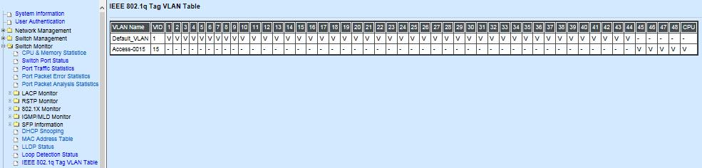
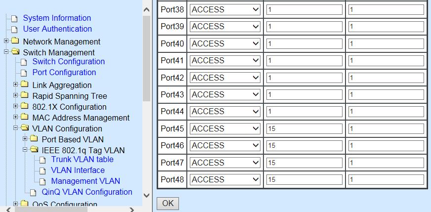

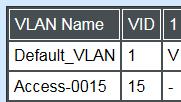
178 178
 Click OK to apply the settings. Note: To check the current status of Management VLAN, please refer to IEEE 802.")
179 2. Now, change the Management VLAN 15 into VLAN 20 and includes Port 45, 46 and 47 under Access mode (It s necessary to include Port 46 to prevent the disconnection.) Click OK to apply the settings. Note: To check the current status of Management VLAN, please refer to IEEE 802.1q Tag VLAN Table or VLAN Interface. 179
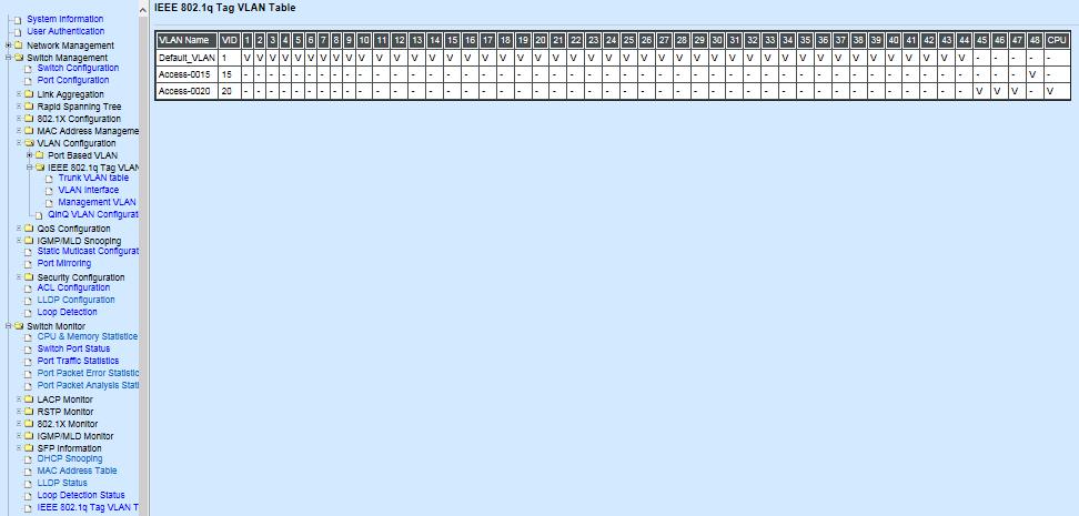


180 180


181 Web Management Configuration (Trunk Mode): In Management VLAN Network Diagram shown below, the management PC on the right would like to manage the Managed Switch on the left remotely. You can follow the steps described below to set up the Management VLAN. Management VLAN Network Diagram Supposed that the Management PC is remotely connected to Managed Switch Port 46 as shown above while we have a various of existing trunk vlan and the Management VLAN 15 is set on Port 45,46,47,48 and CPU as shown below. We can create new Management VLAN 20 as required. This part is to demonstrate how to set up from Management VLAN 15 to VLAN 20 on specified ports under Trunk mode. IEEE 802.1q Tag VLAN Table 181
182 1. Change the Management VLAN 15 into VLAN 20 that includes Port 45, 46, 47 under Trunk mode. Click OK to apply the settings. Note1: Make sure you have correct management VLAN and VLAN Mode configurations, otherwise, incorrect configurations may disconnect your management PC to the Managed Switch immediately when you click OK to apply. Note2: After clicking OK, the checked boxes will soon be emptied because this Management VLAN is for configuration only. To check the current status of Management VLAN, please refer to IEEE 802.1q Tag VLAN Table or VLAN Interface. Then, Management VLAN is changing to VLAN
: VLAN Interface Supposed that we have")

183 IEEE 802.1q Tag VLAN Table CLI Configuration(Access Mode): VLAN Interface Supposed that we have the default Management VLAN whose VLAN ID is 1 for all ports, we can create new Management VLANs as required. This example is to demonstrate how to set up Management VLAN 15 and then change VLAN 15 into VLAN 20 on specified ports under Access mode. 183
184 1. Change the Management default VLAN 1 into VLAN 15 that includes Port 45, 46, 47 and 48 under Access mode. Steps 1. Enter Global Configuration mode. 2. Assign VLAN 15 to Management VLAN and Port to Management port. 3. Show currently configured dot1q settings and check CPU has been a member port in Management VLAN 15. Commands Switch> enable Password: Switch# configure Switch(config)# Switch(config)# vlan management-vlan 15 management-port mode access OK! NOTE: Make sure you have correct management VLAN and VLAN mode configurations, otherwise, incorrect configurations may disconnect your management PC to the Managed Switch immediately when you enter the command. Switch(config)# show vlan dot1q-vlan tag-vlan ============================================================= Configure Trunk VLAN : ============================================================= CPU VLAN ID : 15 Management Priority : 0 VLAN Name VLAN CPU Default_VLAN 1 VVVVVVVV.. VVVVVVVV - Access VVVV V 2. Now, change the Management VLAN 15 into VLAN 20 and includes Port 45, 46 and 47 to Access mode (It s necessary to include Port 46 to prevent the disconnection.) Steps 1. Enter Global Configuration mode. 2. Assign VLAN 20 to Management VLAN and Port to Management port. 3. Show currently configured dot1q settings and check CPU has been a member port in Management VLAN 15 & 20. Commands Switch> enable Password: Switch# configure Switch(config)# Switch(config)# vlan management-vlan 20 management-port mode access OK! NOTE: Make sure you have correct management VLAN and VLAN mode configurations, otherwise, incorrect configurations may disconnect your management PC to the Managed Switch immediately when you enter the command. Switch(config)# show vlan dot1q-vlan tag-vlan ============================================================= Configure Trunk VLAN : ============================================================= CPU VLAN ID : 20 Management Priority : 0 VLAN Name VLAN CPU Default_VLAN 1 VVVVVVVV.. VVVVVVVV - Access V - Access VVV- V 184
185 CLI Configuration(Trunk Mode): This part is to demonstrate how to change Management VLAN 15 into VLAN 20 on specified ports under Trunk mode. Supposed that we have the existing Management VLAN 15 on Port 45,46,47,48 and CPU, we can create new Management VLAN 20 as required. 1. Change the Management VLAN 15 into VLAN 20 that includes Port 45, 46, 47 under Trunk mode. Steps 1. Enter Global Configuration mode. 2. Assign VLAN 20 to Management VLAN and Port to Management port. 3. Show currently configured dot1q settings and check CPU has been a member port in Management VLAN 20. Commands Switch> enable Password: Switch# configure Switch(config)# Switch(config)# vlan management-vlan 20 management-port mode trunk OK! NOTE: Make sure you have correct management VLAN and VLAN mode configurations, otherwise, incorrect configurations may disconnect your management PC to the Managed Switch immediately when you enter the command. Switch(config)# show vlan dot1q-vlan tag-vlan ============================================================= Configure Trunk VLAN : ============================================================= CPU VLAN ID : 20 Management Priority : 0 VLAN Name VLAN CPU Default_VLAN 1 VVVVVVVV.. VVVV V V--V VVVV VVVV VVVV VVVV VVVV VVV- V 185
186 IV. Q-in-Q The IEEE 802.1Q double tagging VLAN is also referred to Q-in-Q or VLAN stacking (IEEE 802.1ad). Its purpose is to expand the 802.1q VLAN space by tagging the inner tagged packets. In this way, a double-tagged frame is created so as to separate customer traffic within a service provider network. As shown below, the network diagram depicts the Switch A (on the left) carries a Customer tag 12. When tagged packets are received on the Managed Switch, they should be tagged with an outer Service Provider tag 15. To set up the network as provided, you can follow the steps described below. CLI Configuration: Steps 1. Enter Global Configuration mode. Q-in-Q VLAN Network Diagram Commands SWH> enable Password: SWH# config SWH(config)# 2. Enable Q-in-Q VLAN SWH(config)# vlan qinq-vlan OK! 3. Assign Port 48 to ISP port SWH(config)# vlan qinq-vlan isp-port 48 OK! 4. Create S-Tag 15 on Port 1. SWH(config)# interface 1 SWH(config-if-1)# vlan qinq-vlan stag-vid 15 OK! 5. Show currently configured dot1q VLAN membership. SWH(config-if-1)# exit SWH(config)# show vlan qinq-vlan ================================================= Q-in-Q VLAN Configuration : ================================================= QinQ VLAN : enable Stag Ethertype : 0x9100 Management Stag : 15 Port Stag VID ISP Port disable 2 1 disable disable 47 1 disable 48 1 enable NOTE: By default, all ports are member ports of the 186


187 Web Management Configuration: Default_VLAN. Before removing the Default_VLAN from the VLAN table, make sure you have correct management VLAN and VLAN mode configurations, otherwise, incorrect configurations may disconnect your management PC to the Managed Switch immediately when you enter the command. 1. Select VLAN Interface option in IEEE 802.1Q Tag VLAN menu. Switch Management>VLAN Configuration>IEEE 802.1q Tag VLAN>VLAN Interface Check the VLAN status. Supposed that Port 1 carries access VLAN 12 while Port 48 trunk VLAN

188 2. Create a new Service VLAN 15 that includes Port 1 and Port 48 as member ports. Switch Management>VLAN Configuration>IEEE 802.1q Tag VLAN>QinQ VLAN Configuration 188

189 Click enable Specify S-tag VID Check ISP port Click OK to apply the settings. NOTE: By default, all ports are member ports of the Default_VLAN. Before removing the Deafult_VLAN from the VLAN table, make sure you have correct management VLAN and PVID configurations, otherwise, incorrect configurations may disconnect your management PC to the Managed Switch immediately when you enter the command. Treatments of Packets: 1. A tagged packet arrives at Port 1 When a packet with a tag 12 arrives at Port 1, the original tag will be kept intact and then added an outer tag 15 by Port 1, which is set as a tunnel port. When this packet is forwarded to Port 48, two tags will be forwarded out because Port 48 is set as a trunk port. 2. A untagged packet arrives at Port 1 If an untagged packet is received, it will also be added a tag 15. However, Q-in-Q function will not work. 189
EPS PoE+ ports 10/100/1000Mbps RJ combo uplink ports (10/100/1000 Mbps RJ-45 and 100/1000Mbps SFP slot) Managed Ethernet PoE Switch
 Managed Ethernet PoE Switch") EPS-3128 24 PoE+ ports 10/100/1000Mbps RJ-45 + 4 combo uplink ports (10/100/1000 Mbps RJ-45 and 100/1000Mbps SFP slot) Managed Ethernet PoE Switch Network Management User s Manual Version 0.90 1 Revision
EPS-3128 24 PoE+ ports 10/100/1000Mbps RJ-45 + 4 combo uplink ports (10/100/1000 Mbps RJ-45 and 100/1000Mbps SFP slot) Managed Ethernet PoE Switch Network Management User s Manual Version 0.90 1 Revision
HES-3106 SERIES 6 PORTS 10/100/1000BASE-T ETHERNET MANAGED SWITCH
 HES-3106 SERIES 6 PORTS 10/100/1000BASE-T ETHERNET MANAGED SWITCH 5 PORTS 10/100/1000BASE-T ETHERNET MANAGED SWITCH WITH 1 PORT 1000BASE-X or 100/1000BASE-X UPLINK 5 PORTS 10/100/1000BASE-T ETHERNET MANAGED
IPS-3106 SERIES Managed Industrial PoE Ethernet Switch
 IPS-3106 SERIES Managed Industrial PoE Ethernet Switch Network Management User s Manual Version 0.96 1 Trademarks Contents are subject to revision without prior notice. All other trademarks remain the
HES-3109SSFP-DR. 8 ports 10/100/1000Mbps RJ port 100/1000Mbps SFP slot Uplink Managed Ethernet CPE Switch. Network Management.
 HES-3109SSFP-DR 8 ports 10/100/1000Mbps RJ45 + 1 port 100/1000Mbps SFP slot Uplink Managed Ethernet CPE Switch Network Management User s Manual Version 0.94 1 Revision History Version F/W Date Description
HES-3106SFP-F2 6-port L2+ Managed Gigabit Fiber Switch User s Guide
 HES-3106SFP-F2 6-port L2+ Managed Gigabit Fiber Switch User s Guide Version: 1.0 Revision History Version Date Changes 1.0 11/07/2018 First release FCC Warning This equipment has been tested and found
FRG-3105 Series Residential Gateway
 FRG-3105 Series Residential Gateway Network Management User s Manual Version 0.90 1 Trademarks Contents are subject to revision without prior notice. All other trademarks remain the property of their respective
icpe Gateway Controller
 icpe Gateway Controller Network Management User s Manual Version 0.90 1 Trademarks Contents are subject to revision without prior notice. All other trademarks remain the properties of their owners. Copyright
HET-2106 SERIES. 5 ports 10/100Mbps RJ port 100Mbps fiber optics uplink Managed Ethernet CPE Switch. Network Management.
 HET-2106 SERIES 5 ports 10/100Mbps RJ-45 + 1 port 100Mbps fiber optics uplink Managed Ethernet CPE Switch Network Management User s Manual Version 0.97 1 Trademarks CTS is a registered trademark of Connection
FWR Series Residential Gateway
 FWR5-3105 Series Residential Gateway Network Management User s Manual Version 0.92 1 Trademarks Contents are subject to revision without prior notice. All other trademarks remain the property of their
HES-3106-PLUS SERIES
 HES-3106-PLUS SERIES 5 PORTS 10/100/1000BASE-T ETHERNET MANAGED SWITCH WITH 1 PORT 1000BASE-X or 100/1000BASE-X UPLINK User s Guide Version 0.92 Trademarks CTS is a registered trademark of Connection Technology
HES-3109 SERIES 9 PORTS 10/100/1000BASE-T MANAGEMENT ETHERNET SWITCH
 HES-3109 SERIES 9 PORTS 10/100/1000BASE-T MANAGEMENT ETHERNET SWITCH 8 PORTS 10/100/1000BASE-T MANAGEMENT ETHERNET SWITCH WITH 1 PORT 1000BASE-X UPLINK OR 1 PORT 100/1000BASE-X UPLINK 8 PORTS 10/100/1000BASE-T
Network Management. User s Manual. Version: 0.90
 MCT-RACK-12-MGM 12 SLOTS COMPACT MEDIA CONVERTER CENTER Network Management User s Manual Version: 0.90. Trademarks CTS is a registered trademark of Connection Technology Systems Inc.. Contents are subject
SD24GS. 24-Port Web Smart Gigabit Ethernet Switch. User s Manual
 SD24GS 24-Port Web Smart Gigabit Ethernet Switch User s Manual FCC Warning This equipment has been tested and found to comply with the limits for a Class A digital device, pursuant to Part 15 of the FCC
FWRIII-2105 SERIES. 4 ports 10/100Mbps RJ-45; built-in IEEE802.11n WiFi and 1 port 100Mbps SFP slot uplink Residential Gateway. Residential Gateway
 FWRIII-2105 SERIES 4 ports 10/100Mbps RJ-45; built-in IEEE802.11n WiFi and 1 port 100Mbps SFP slot uplink Residential Gateway 4 ports 10/100Mbps RJ-45; built-in IEEE802.11n WiFi and 1 port 100Mbps SFP
SWP-0208G, 8+2SFP. 8-Port Gigabit Web Smart Switch. User s Manual
 SWP-0208G 1 SWP-0208G, 8+2SFP 8-Port Gigabit Web Smart Switch User s Manual Version: 3.4 April 1, 2008 2 TABLE OF CONTENT 1.0 INTRODUCTION...4 1.1 MAIN FEATURES...4 1.2 START TO MANAGE THIS SWITCH...6
48-Port 10/100Mbps + 4 Gigabit TP / 2 SFP Managed Switch
 High-Density / Cost-effective / Powerful class Fast Ethernet solution for SMB / Enterprise Network The PLANET is 48-Port 10/100Mbps + 4 Gigabit TP / 2 SFP Managed Switch with advanced Web-based management
FOS-3114 Series 14-port L2+ Managed Gigabit Fiber Switch User s Guide
 FOS-3114 Series 14-port L2+ Managed Gigabit Fiber Switch User s Guide Version: 1.1 Revision History Version Date Changes 1.0 12/21/2017 First release 1.1 02/27/2018 Add the new feature FCC Warning This
SWH-3112 Series 12-port L2+ Managed Gigabit Fiber Switch User s Guide
 SWH-3112 Series 12-port L2+ Managed Gigabit Fiber Switch User s Guide Version: 1.0 Revision History Version Date Changes 0.9 11/10/2017 First release 1.0 05/08/2018 Use the new template FCC Warning This
Management Software AT-S101. User s Guide. For use with the AT-GS950/8POE Gigabit Ethernet WebSmart Switch. Version Rev.
 Management Software AT-S101 User s Guide For use with the AT-GS950/8POE Gigabit Ethernet WebSmart Switch Version 1.0.0 613-000985 Rev. A Copyright 2008 Allied Telesis, Inc. All rights reserved. No part
CVT-2512 SERIES CVT-3512 SERIES
 CVT-2512 SERIES 10/100BASE-TX to 100BASE-FX Standalone Managed Media Converter with 802.3ah OAM compliance CVT-3512 SERIES 10/100/1000BASE-T to 1000BASE-X Standalone Managed Media Converter with 802.3ah
IPS-3110 Managed Industrial PoE Gigabit Ethernet Switch
 IPS-3110 Managed Industrial PoE Gigabit Ethernet Switch User s Guide Version 0.90 Trademarks Contents are subject to revision without prior notice. All other trademarks remain the property of their respective
ProSAFE 8-Port and 16-Port 10-Gigabit Ethernet Web Managed Switch Models XS708Ev2 and XS716E User Manual
 ProSAFE 8-Port and 16-Port 10-Gigabit Ethernet Web Managed Switch Models XS708Ev2 and XS716E User Manual March 2017 202-11656-03 350 East Plumeria Drive San Jose, CA 95134 USA Support Thank you for purchasing
Management Software AT-S79. User s Guide. For use with the AT-GS950/16 and AT-GS950/24 Smart Switches. Version Rev.
 Management Software AT-S79 User s Guide For use with the AT-GS950/16 and AT-GS950/24 Smart Switches Version 1.0.0 613-000207 Rev. A Copyright 2005 Allied Telesyn, Inc. All rights reserved. No part of this
IN-16POEGWM. User Manual. 16 Port Gigabit Ethernet + 4 Combo Gigabit SFP PoE Web Smart Switch
 IN-16POEGWM User Manual 16 Port Gigabit Ethernet + 4 Combo Gigabit SFP PoE Web Smart Switch FCC Warning This Equipment has been tested and found to comply with the limits for a Class-A digital device,
16-SLOT IN-BAND MANAGEMENT CHASSIS
 FCM-CHS2-XX 16-SLOT IN-BAND MANAGEMENT CHASSIS Network Management Manual Version 2.2 1 FCC Warning This equipment has been tested and found to comply with the limits for a Class A digital device, pursuant
FRG-3105 Series Residential Gateway
 FRG-3105 Series Residential Gateway User s Guide Version 0.90 Revision History Version Date Description 0.90 20170605 First Release 2 Trademarks Contents are subject to revision without prior notice. All
SW24MGSFP 10/100/1000 Mbps + 2 Gb SFP Web Smart Ethernet Switch User Manual Version 1.0 (January 2011)
") SW24MGSFP 10/100/1000 Mbps + 2 Gb SFP Web Smart Ethernet Switch User Manual Version 1.0 (January 2011) TABLE OF CONTENTS PACKING LIST... 1 PRODUCT OVERVIEW... 3 FEATURES... 3 HARDWARE INSTALLATION... 4
SW24MGSFP 10/100/1000 Mbps + 2 Gb SFP Web Smart Ethernet Switch User Manual Version 1.0 (January 2011) TABLE OF CONTENTS PACKING LIST... 1 PRODUCT OVERVIEW... 3 FEATURES... 3 HARDWARE INSTALLATION... 4
ProSAFE 8-Port 10-Gigabit Web Managed Switch Model XS708Ev2 User Manual
 ProSAFE 8-Port 10-Gigabit Web Managed Switch Model XS708Ev2 User Manual April 2016 202-11656-01 350 East Plumeria Drive San Jose, CA 95134 USA Support Thank you for purchasing this NETGEAR product. You
Getting Started with the VG248
 CHAPTER 2 Before you can configure the telephony features on the VG248 to interact with the analog phones, you must first configure the basic network, SNMP, and password settings. These settings enable
48-Port Gigabit with 4 Shared SFP Managed Switch
 48-Port Gigabit with 4 Shared SFP Managed Switch High-Density / Cost-effective / Telecom class Gigabit solution for Enterprise backbone and Data Center Networking The PLANET is a Layer 2 / Layer 4 full
8-Port 10/100Mbps + 2G TP / SFP Combo Managed Switch
 8-Port 10/100Mbps + 2G TP / SFP Combo Managed Switch Full-Functioned / Robust Layer2 Features Layer 2 / Layer 4 Managed Switch for Enterprise and Campus Networking The PLANET is an 8-Port 10/100Mbps Fast
ES Port Managed Gigabit Switch with 4 SFP ports
 ES220-28 28-Port Managed Gigabit Switch with 4 SFP ports Overview With the increasing number of wired and wireless network device, the SOARNEX SOAR series, ES220-28, provides a cost-effective solution
SOLO NETWORK (11) (21) (31) (41) (48) (51) (61)
 (21) (31) (41) (48) (51) (61)") (11) 4062-6971 (21) 4062-6971 (31) 4062-6971 (41) 4062-6971 (48) 4062-6971 (51) 4062-6971 (61) 4062-6971 Cisco SRW224G4 24-Port 10/100 + 4-Port Gigabit Switch: WebView Cisco Small Business Managed Switches
(11) 4062-6971 (21) 4062-6971 (31) 4062-6971 (41) 4062-6971 (48) 4062-6971 (51) 4062-6971 (61) 4062-6971 Cisco SRW224G4 24-Port 10/100 + 4-Port Gigabit Switch: WebView Cisco Small Business Managed Switches
48-Port 10/100/1000BASE-T + 4-Port 100/1000BASE-X SFP Gigabit Managed Switch GS T4S
 48-Port 10/100/1000BASE-T + 4-Port 100/1000BASE-X SFP Gigabit Managed Switch GS-4210-48T4S Outlines Product Overview Product Benefits Applications Appendix Product Features 2 / 42 Product Overview Layer
8-port mk2 user s guide v port mk2
 8-port mk2 1 CONTENT The 8-port mk2... 4 Connection example... 5 User Login... 6 Switch Status... 7 System information... 7 Logging message... 7 Port counters... 8 Aggregation state... 8 LLDP statistics...
Gigabit Managed Ethernet Switch
 LGB1110A LGB1126A-R2 Product Data Sheet Gigabit Managed Ethernet Switch Features Overview LGB1110A The Gigabit Managed Ethernet Switches offer L2 features plus advanced L3 features such as Static Route
VERTICAL HORIZON VH-2402S FAST ETHERNET SWITCH MANAGEMENT GUIDE
 VERTICAL HORIZON VH-2402S FAST ETHERNET SWITCH MANAGEMENT GUIDE 9033645-01 Notice Only qualified personnel should perform installation procedures. NOTICE Enterasys Networks reserves the right to make
Security SSID Selection: Broadcast SSID:
 69 Security SSID Selection: Broadcast SSID: WMM: Encryption: Select the SSID that the security settings will apply to. If Disabled, then the device will not be broadcasting the SSID. Therefore it will
LevelOne GES GE with 1 Combo SFP Web Smart Switch User Manual
 LevelOne GES-0852 8 GE with 1 Combo SFP Web Smart Switch User Manual Version 1.0-1109 1 FCC Certifications This Equipment has been tested and found to comply with the limits for a Class A digital device,
EP Port Managed Gigabit Switch with 4 x IEEE 802.3at + 20 x IEEE 802.3af PoE
 EP220-28-193 28-Port Managed Gigabit Switch with 4 x IEEE 802.3at + 20 x IEEE 802.3af PoE Overview To fulfill the needs of higher power requirement of PoE network applications with Gigabit speed transmission,
802.11a g Dual Band Wireless Access Point. User s Manual
 802.11a+802.11g Dual Band Wireless Access Point User s Manual 0 Chapter 1 Introduction 1.1 Feature Fully interoperable with IEEE 802.11b compliant products. High-Speed data transfer rate up to 11Mbps.
16-Port Web Smart Gigabit Ethernet Switch with 2 Shared SFP Interfaces GSW-1602SF Data Sheet
 16-Port Web Smart Gigabit Ethernet Switch with 2 Shared SFP Interfaces Robust Layer 2 Features High-Performaning Gigabit Solution for Enterprise Backbone and Data Center Networking PLANET's is a Layer
SOLO NETWORK (11) (21) (31) (41) (48) (51) (61)
 (21) (31) (41) (48) (51) (61)") (11) 4062-6971 (21) 4062-6971 (31) 4062-6971 (41) 4062-6971 (48) 4062-6971 (51) 4062-6971 (61) 4062-6971 Cisco SRW2024 24-Port Gigabit Switch: WebView Cisco Small Business Managed Switches Highly Secure,
(11) 4062-6971 (21) 4062-6971 (31) 4062-6971 (41) 4062-6971 (48) 4062-6971 (51) 4062-6971 (61) 4062-6971 Cisco SRW2024 24-Port Gigabit Switch: WebView Cisco Small Business Managed Switches Highly Secure,
28 Port Fiber Gigabit with 10G SFP+ Management Switch
 28 Port Fiber Gigabit with 10G SFP+ Management Switch ES220-28-24F Gigabit Fiber applies in longer distance for Surveillance, Enterprise, Campuses and Data Centers To meet the backbone application of surveillance,
Cisco SRW Port Gigabit Switch: WebView Cisco Small Business Managed Switches
 Cisco SRW2016 16-Port Gigabit Switch: WebView Cisco Small Business Managed Switches Secure, Reliable, Intelligent Switching for Small Businesses Highlights 16 high-speed ports optimized for the network
24-Port 100Base-FX SFP + 2- Gigabit Managed Ethernet Switch
 24-Port Base-FX SFP + 2- Gigabit Managed Ethernet Switch Multi Port / Flexible Base-FX Fiber Optical connective for Distance Extension Solution The FTTx network applications are part of our life particularly
RANGER SERIES. 150Mbps Wireless Green Broadband Router DG-BR4000NG. 150 Mbps V
 RANGER SERIES 150Mbps Wireless Green Broadband Router DG-BR4000NG N 150 Mbps V1.2 2011-12-15 FCC warning: This equipment has been tested and found to comply with the limits for a class B digital device,
WGSW Data Sheet
 28-Port 10/100/Mbps with 4 Shared SFP Managed Switch PLANET introduces the latest Managed Gigabit Switch - that is perfectly designed for SMB and SOHO network construction. Besides the hot IPv6 / IPv4
TL-SG2216/TL-SG2424/TL-SG2424P/TL-SG2452. Gigabit Smart Switch REV
 TL-SG2216/TL-SG2424/TL-SG2424P/TL-SG2452 Gigabit Smart Switch REV2.0.0 1910011094 COPYRIGHT & TRADEMARKS Specifications are subject to change without notice. is a registered trademark of TP-LINK TECHNOLOGIES
Product features. Applications
 Applications Layer 2+ VLAN static routing application The managed switch features a built-in, robust IPv4/IPv6 Layer 3 traffic static routing protocol to ensure reliable routing between VLANs and network
IPS-3106-SE-PB Managed Industrial PoE Ethernet Switch User s Guide
 IPS-3106-SE-PB Managed Industrial PoE Ethernet Switch User s Guide Version: 1.2 Revision History Version Date Changes 1.0 04/19/2018 First release 1.1 06/12/2018 Add new features and CTS branches contact
GS-1626G Web Smart+ GbE Switch
 GS-1626G Web Smart+ GbE Switch Overview GS-1626G Web Smart+ Managed Switch is a next-generation Ethernet Switch offering powerful L2 features and Layer 3 Static Route that delivers the cost-effectively
T PCT. Smart PoE Switch REV
 T1500-28PCT Smart PoE Switch REV1.0.0 1910011255 COPYRIGHT & TRADEMARKS Specifications are subject to change without notice. is a registered trademark of TP-LINK TECHNOLOGIES CO., LTD. Other brands and
JSH2402GBM. Introduction. Main Features Combo Port Mixed Giga Ethernet SNMP Switch. Picture for reference
 JSH2402GBM 24+2 Combo Port Mixed Giga Ethernet SNMP Switch Introduction Picture for reference The 24+2 Combo Port Mixed Giga Ethernet SNMP Switch is ideal for medium to large Internet bar or enterprise,
Cisco Small Business Managed Switches
 Cisco SRW208L 8-Port 10/100 Ethernet Switch: WebView/LX Uplink Cisco Small Business Managed Switches Secure, Reliable, Intelligent Switching for Small Businesses Highlights Connects up to eight network
MR2324-4C. 24-Port Intelligent Gigabit Ethernet Switch. Management Guide
 MR2324-4C 24-Port Intelligent Gigabit Ethernet Switch Management Guide Management Guide Intelligent Gigabit Ethernet Switch with 24 10/100/1000BASE-T (RJ-45) Ports, and 4 Combination RJ-45/SFP Ports E082004-R01
8-Port 10/100/1000 Gigabit Switch. User Guide. with WebView WIRED SRW2008/SRW2008P/SRW2008MP. Model No.
 8-Port 10/100/1000 Gigabit Switch with WebView WIRED User Guide Model No. SRW2008/SRW2008P/SRW2008MP Copyright and Trademarks Specifications are subject to change without notice. Linksys is a registered
SOLO NETWORK (11) (21) (31) (41) (48) (51) (61)
 (21) (31) (41) (48) (51) (61)") Cisco SLM224G 24-Port 10/100 + 2-port Gigabit Smart Switch: SFPs Cisco Small Business Smart Switches Cost-Effective, Secure Switching with Simplified Management for Small Businesses Highlights Connect
Cisco SLM224G 24-Port 10/100 + 2-port Gigabit Smart Switch: SFPs Cisco Small Business Smart Switches Cost-Effective, Secure Switching with Simplified Management for Small Businesses Highlights Connect
Index. B Boot software 5-2 Bridging architecture 7-6 Broadcast filter 8-55 limiting 8-22 Buffer port 7-9 Syslog 8-17, 8-20
 Index Numerics 10/100 mode 8-27 1000BaseLx 7-10 1000BaseSx 7-10 1000BaseT 7-10 100BaseFx 7-10 100BaseFx Ports 7-10 100BaseTx 7-10 10BaseT 7-10 802.3x Gigabit negotiation 8-29 9304M Routing Switch 2-9 9308M
PSGS-2610F L2+ Managed GbE PoE Switch
 PSGS-2610F L2+ Managed GbE PoE Switch Overview PSGS-2610F L2+ Managed PoE+ Switch is a next-generation Ethernet Switch offering full suite of L2 features, better PoE functionality and usability, including
24-Port 10/100TX + 4-Port Gigabit Managed Switch with 2 Combo 100/1000X SFP Ports
 24-Port 10/100TX + 4-Port Gigabit Managed Switch with 2 Combo 100/X SFP Ports Full-Functioned Layer 2 / Layer 4 Managed Switch for Enterprise and Campus Networking PLANET is a 24-port 10/100Mbps Fast Ethernet
SOLO NETWORK (11) (21) (31) (41) (48) (51) (61)
 (21) (31) (41) (48) (51) (61)") (11) 4062-6971 (21) 4062-6971 (31) 4062-6971 (41) 4062-6971 (48) 4062-6971 (51) 4062-6971 (61) 4062-6971 Cisco SRW208MP 8-Port 10/100 Ethernet Switch: WebView/Max PoE Cisco Small Business Managed Switches
(11) 4062-6971 (21) 4062-6971 (31) 4062-6971 (41) 4062-6971 (48) 4062-6971 (51) 4062-6971 (61) 4062-6971 Cisco SRW208MP 8-Port 10/100 Ethernet Switch: WebView/Max PoE Cisco Small Business Managed Switches
Peplink SD Switch User Manual. Published on October 25th, 2018
 Peplink SD Switch User Manual Published on October 25th, 2018 1 Table of Contents Switch Layout 4 Specifications 5 Hardware Overview 6 Quick Start Functions 7 Reset Switch 7 Connect Ethernet 7 Connect
Figure 35: Active Directory Screen 6. Select the Group Policy tab, choose Default Domain Policy then click Edit.
 PC and Server Configuration Figure 35: Active Directory Screen 6. Select the Group Policy tab, choose Default Domain Policy then click Edit. Figure 36: Group Policy Tab 7. Select Computer Configuration
AT-GS950/10PS Switch Web Interface User s Guide AT-S110 [ ]
![AT-GS950/10PS Switch Web Interface User s Guide AT-S110 [ ]](/thumbs/85/92714654.jpg "AT-GS950/10PS Switch Web Interface User s Guide AT-S110 [ ]") AT-GS950/10PS Gigabit Ethernet PoE+ Switch AT-GS950/10PS Switch Web Interface User s Guide AT-S110 [1.00.013] 613-001770 Rev A Copyright 2013 Allied Telesis, Inc. All rights reserved. No part of this publication
AT-GS950/10PS Gigabit Ethernet PoE+ Switch AT-GS950/10PS Switch Web Interface User s Guide AT-S110 [1.00.013] 613-001770 Rev A Copyright 2013 Allied Telesis, Inc. All rights reserved. No part of this publication
SOLO NETWORK (11) (21) (31) (41) (48) (51) (61)
 (21) (31) (41) (48) (51) (61)") (11) 4062-6971 (21) 4062-6971 (31) 4062-6971 (41) 4062-6971 (48) 4062-6971 (51) 4062-6971 (61) 4062-6971 Cisco SRW208P 8-Port 10/100 Ethernet Switch: WebView/PoE Cisco Small Business Managed Switches Highly
(11) 4062-6971 (21) 4062-6971 (31) 4062-6971 (41) 4062-6971 (48) 4062-6971 (51) 4062-6971 (61) 4062-6971 Cisco SRW208P 8-Port 10/100 Ethernet Switch: WebView/PoE Cisco Small Business Managed Switches Highly
Managed Ethernet Switch User s Manual
 Managed Ethernet Switch User s Manual Information Coding: UM00D908 Version: V1.1 Product version: all Product Name: Managed Industrial Ethernet Switches on DIN Rail and Rack. Applicable to: Technical Support
Gigabit Managed Ethernet Switch
 LGB1110A LGB1152A Product Data Sheet Gigabit Managed Ethernet Switch LGB1110A OVERVIEW The Gigabit Managed Ethernet Switches offer L2 features plus advanced L3 features such as Static Route for Enterprise
Gigabit Managed Ethernet Switch
 LGB1110A LGB1126A-R2 LGB1152A Product Data Sheet Gigabit Managed Ethernet Switch FEATURES L2+ features make the switch easy to manage, provide robust security, and QoS. Offers a built-in device management
24-Port 10/100TX + 4-Port Gigabit Managed Switch with 2 Combo 100/1000X SFP Ports FGSW-2840 Data Sheet Layer 2 Features
 24-Port 10/100TX + 4-Port Gigabit Managed Switch with 2 Combo 100/X SFP Ports 1 Layer 2 / Layer 4 Managed Switch for Enterprise and Campus Networking PLANET's is a 24-port 10/100Mbps Fast Ethernet Switch
CISCO SRW208MP-EU SWITCH 8 x 10/100 PoE /100/1000 mini-gbic porttia, WebView/ Max PoE
 CISCO SRW208MP-EU SWITCH 8 x 10/100 PoE + 2 10/100/1000 mini-gbic porttia, WebView/ Max PoE Specifications Ports 8 RJ-45 connectors for 10BASE-T and 100BASE-TX, 2 RJ-45 connectors for 10BASE-T/100BASE-
CHAPTER 2 ACTIVITY
 CHAPTER 2 ACTIVITY 2.1.1.1 1. CLI stands for 2. GUI stands for 3. Write the step you used to go to CLI interface on Windows 4. The OS, normally loads from a disk drive, into RAM. 5. The portion of the
L Port 10/100/1000T PoE + 2-Port Gigabit SFP + Managed Switch
 L2 + 24-Port 10/100/1000T PoE + 2-Port Gigabit SFP + Managed Switch PS-B8266VF series are high performance and cost efficiency 802.3af/at PoE Smart Switch. It comes with 24 dedicated 10/100/1000Mbps PSE
Web Browser User s Guide
 Management Software AT-S63 Web Browser User s Guide For AT-9400Ts Stacks AT-S63 Version 4.0.0 for AT-9400 Basic Layer 3 Switches PN 613-001028 Rev B Copyright 2009 Allied Telesis, Inc. All rights reserved.
SOLO NETWORK (11) (21) (31) (41) (48) (51) (61)
 (21) (31) (41) (48) (51) (61)") (11) 4062-6971 (21) 4062-6971 (31) 4062-6971 (41) 4062-6971 (48) 4062-6971 (51) 4062-6971 (61) 4062-6971 Cisco SRW224G4P 24-Port 10/100 + 4-Port Gigabit Switch: WebView/PoE Cisco Small Business Managed
(11) 4062-6971 (21) 4062-6971 (31) 4062-6971 (41) 4062-6971 (48) 4062-6971 (51) 4062-6971 (61) 4062-6971 Cisco SRW224G4P 24-Port 10/100 + 4-Port Gigabit Switch: WebView/PoE Cisco Small Business Managed
GS-2610G L2+ Managed GbE Switch
 GS-2610G L2+ Managed GbE Switch Overview GS-2610G L2+ Managed Switch is a next-generation Ethernet Switch offering full suite of L2 features, including advanced L3 features such as Static Route that delivers
GV-PoE Switch. Multicam Digital. GV-POE0811 User's Manual
 GV-PoE Switch Multicam Digital GV-POE0811 User's Manual Before attempting to connect or operate this product, please read these instructions carefully and save this manual for future use. POE0811-A 2014
Managed Gigabit PoE Switch PS2460GM
 Managed Gigabit PoE Switch PS2460GM Description PS2460GM Enterprise Gigabit Ethernet switch with management function is designed to meet rigorous mission critical applications, such as factory automation,
Gigabit Network Switches
 Network Transmission Gigabit Network Switches Layer 2 (Non-PoE) Layer 3 (PoE-at) OVERVIEW This Enterprise-Class Network Switch provides 24 Gigabit Ethernet ports with 4 shared 100/1000Mbps SFP slots. This
SOLO NETWORK (11) (21) (31) (41) (48) (51) (61)
 (21) (31) (41) (48) (51) (61)") (11) 4062-6971 (21) 4062-6971 (31) 4062-6971 (41) 4062-6971 (48) 4062-6971 (51) 4062-6971 (61) 4062-6971 Cisco SLM248P 48-Port 10/100 + 2-Port Gigabit Smart Switch: SFPs/PoE Cisco Small Business Smart
(11) 4062-6971 (21) 4062-6971 (31) 4062-6971 (41) 4062-6971 (48) 4062-6971 (51) 4062-6971 (61) 4062-6971 Cisco SLM248P 48-Port 10/100 + 2-Port Gigabit Smart Switch: SFPs/PoE Cisco Small Business Smart
AT-S41 Version 1.1.7C Management Software for the AT-8326GB and AT-8350GB Series Fast Ethernet Switches. Software Release Notes
 AT-S41 Version 1.1.7C Management Software for the AT-8326GB and AT-8350GB Series Fast Ethernet Switches Software Release Notes Please read this document before you begin to use the AT-S41 management software.
TL-SL2210/TL-SL2218/TL-SL2428/TL-SL2452. Smart Switch REV
 TL-SL2210/TL-SL2218/TL-SL2428/TL-SL2452 Smart Switch REV1.2.1 1910011603 COPYRIGHT & TRADEMARKS Specifications are subject to change without notice. is a registered trademark of TP-LINK TECHNOLOGIES CO.,
Cisco SGE Port Gigabit Switch Cisco Small Business Managed Switches
 Cisco SGE2000 24-Port Gigabit Switch Cisco Small Business Managed Switches High-Performance, Reliable, Stacking Switch for Small Businesses Highlights 24 high-speed ports optimized for the network core
FGS-2616X L2+ Managed GbE Fiber Switches
 FGS-2616X L2+ Managed GbE Fiber Switches FGS-2616XD FGS-2616XA FGS-2616X Overview FGS-2616X series L2+ Managed Switch are next-generation Fiber Switch offering full suite of L2 features and additional
Quick Start Guide Elinx ESW500 Series. Managed Din Rail Ethernet Switch
 Quick Start Guide Elinx ESW500 Series Managed Din Rail Ethernet Switch ESW500 Series Documentation Number: ESW500series-1012qsg International Headquarters: 707 Dayton Road Ottawa, IL 61350 USA Phone (815)
AMG9082W-HP260-C User s Manual
 8 x 10/100 PoE+ 802.3at w/ 2 Gigabit Combo Ports RJ45/SFP Fast Ethernet Switch AMG9082W-HP260-C User s Manual www.amgsystems.com FCC Warning This Equipment has been tested and found to comply with the
IN-16POEWM. User Manual. 16 Port Fast Ethernet PoE Web Smart Switch. Version V100817
 IN-16POEWM User Manual 16 Port Fast Ethernet PoE Web Smart Switch Version V100817 FCC Warning This Equipment has been tested and found to comply with the limits for a Class-A digital device, pursuant to
TD-8616 ADSL2/2+ Ethernet Modem
 TD-8616 ADSL2/2+ Ethernet Modem Rev: 1.0.1 1910010001 COPYRIGHT & TRADEMARKS Specifications are subject to change without notice. is a registered trademark of TP-LINK TECHNOLOGIES CO., LTD. Other brands
Nighthawk S8000 Gaming & Streaming Advanced 8-Port Gigabit Ethernet Switch User Manual
 Nighthawk S8000 Gaming & Streaming Advanced 8-Port Gigabit Ethernet Switch User Manual Model GS808E March 2017 202-11732-01 350 E. Plumeria Drive San Jose, CA 95134 USA Support Thank you for purchasing
AC1200M/MS. User Manual
 AC1200M/MS User Manual Table of Contents User Manual... 1 1 Preface... 1 2 LED Indicators and Connectors... 1 2.1 LED Indicators... 1 2.2 Hardware Installation... 2 3 Voice Prompt (AC1200MS)... 2 4 User
NGSME16T2H. (16-port 10/100/1000Base-T + 2 Gigabit SFP L2+ Management PoE Switch)
") NGSME16T2H (16-port 10/100/1000Base-T + 2 Gigabit SFP L2+ Management PoE Switch) More information: WWW.NIVEOPROFESSIONAL.COM INFO@NIVEOPROFESSIONAL.COM Product Specification Introduction The NGSM16ET2H
NGSME16T2H (16-port 10/100/1000Base-T + 2 Gigabit SFP L2+ Management PoE Switch) More information: WWW.NIVEOPROFESSIONAL.COM INFO@NIVEOPROFESSIONAL.COM Product Specification Introduction The NGSM16ET2H
SOLO NETWORK (11) (21) (31) (41) (48) (51) (61)
 (21) (31) (41) (48) (51) (61)") Cisco SRW2008MP 8-Port Gigabit Switch: WebView/Max PoE Cisco Small Business Managed Switches Secure, Reliable, Intelligent, Managed Gigabit Switching with PoE for Small Businesses Highlights Eight high-speed
Cisco SRW2008MP 8-Port Gigabit Switch: WebView/Max PoE Cisco Small Business Managed Switches Secure, Reliable, Intelligent, Managed Gigabit Switching with PoE for Small Businesses Highlights Eight high-speed
TECH. MGS2924G: 16-Port SFP + 8-Port Combo GbE L2 Plus Managed Switch
 TECH MGS2924G MGS2924G: 16-Port SFP + 8-Port Combo GbE Key Features 24-Port Gigabit SFP high port count fiber switch 9KB jumbo frame support IEEE 802.1x Access Control improves network security Port Mirroring
CTS-iCPE Gateway Controller User s Manual Version: Revision B1
 CTS-iCPE Gateway Controller User s Manual Version: Revision B1 Trademarks Contents are subject to revision without prior notice. All other trademarks remain the property of their respective owners. Copyright
SFTOS Configuration Guide
 SFTOS Configuration Guide Version 2.5.3.0 August 2008 Edition Copyright 2008 Force10 Networks All rights reserved. Printed in the USA. August 2008. Force10 Networks reserves the right to change, modify,
24-Port 10/100/1000Mbps with 4 Shared SFP Managed Switch
 24-Port 10/100/Mbps with 4 Shared SFP Managed Switch High-Performing Gigabit Solution for Enterprise and Data Centers PLANET's series Switch, which includes the and the models. The Layer 2 Managed Gigabit
24-Port: 20 x (100/1000M) SFP + 4 x Combo (10/100/1000T or 100/1000M SFP)
 SFP + 4 x Combo (10/100/1000T or 100/1000M SFP)") BGS-20DSFP4C Managed Fiber Switch 24-Port: 20 x (100/1000M) SFP + 4 x Combo (10/100/1000T or 100/1000M SFP) Key Features L2+ features provide better manageability, security, QOS, and performance IEEE 802.3az
BGS-20DSFP4C Managed Fiber Switch 24-Port: 20 x (100/1000M) SFP + 4 x Combo (10/100/1000T or 100/1000M SFP) Key Features L2+ features provide better manageability, security, QOS, and performance IEEE 802.3az
Save installation time and money with PoE.
 48-Port Gigabit Ethernet PoE+ Layer2+ Managed Switch with 10 GbE Uplink 48 x PoE ports, IEEE 802.3at Power over Ethernet (PoE+), Layer 2+, 2 x 10 GbE SFP+ open slots, Endspan, 19" Rackmount Part No.: 561112
20 GE PoE-Plus + 4 GE PoE-Plus Combo SFP + 2 GE SFP L2 Managed Switch, 185W
 GEP-2671 Version: 1 20 GE PoE-Plus + 4 GE PoE-Plus Combo SFP + 2 GE SFP L2 Managed Switch, 185W The LevelOne GEP-2671 is a Layer 2 Managed switch with 24 x 1000Base-T PoE-Plus ports associated with 4 x
NGSME24T2H-AV. (24-Rear Port 10/100/1000Base-T PoE + 2 Gigabit SFP Layer 2+ Management Current Sharing PoE+ Switch)
") NGSME24T2H-AV (24-Rear Port 10/100/1000Base-T PoE + 2 Gigabit SFP Layer 2+ Management Current Sharing PoE+ Switch) More information: WWW.NIVEOPROFESSIONAL.COM INFO@NIVEOPROFESSIONAL.COM Product Specification
NGSME24T2H-AV (24-Rear Port 10/100/1000Base-T PoE + 2 Gigabit SFP Layer 2+ Management Current Sharing PoE+ Switch) More information: WWW.NIVEOPROFESSIONAL.COM INFO@NIVEOPROFESSIONAL.COM Product Specification