FWR Series Residential Gateway
|
|
|
- Bertina Sullivan
- 5 years ago
- Views:
Transcription

1 FWR Series Residential Gateway Network Management User s Manual Version
2 Trademarks Contents are subject to revision without prior notice. All other trademarks remain the property of their respective owners. Copyright Statement Copyright 2016, All Rights Reserved. This publication may not be reproduced as a whole or in part, in any way whatsoever unless prior consent has been obtained from Company. FCC Warning This equipment has been tested and found to comply with the limits for a Class-A digital device, pursuant to Part 15 of the FCC Rules. These limitations are designed to provide reasonable protection against harmful interference in a residential installation. This equipment generates uses and can radiate radio frequency energy. If this equipment is not installed properly and used in accordance with the instructions, may cause harmful interference to radio communications. However, there is no guarantee that interference will not occur in a particular installation. If this equipment does cause harmful interference to radio or television reception, which can be determined by turning the equipment off and on, the user is encouraged to try to correct the interference by one or more of the following measures: Reorient or relocate the receiving antenna. Increase the separation between the equipment and receiver. Connect the equipment into a different outlet from that the receiver is connected. Consult your local distributors or an experienced radio/tv technician for help. Shielded interface cables must be used in order to comply with emission limits. Changes or modifications to the equipment, which are not approved by the party responsible for compliance, could affect the user s authority to operate the equipment. Copyright 2016 All Rights Reserved. Company has an on-going policy of upgrading its products and it may be possible that information in this document is not up-to-date. Please check with your local distributors for the latest information. No part of this document can be copied or reproduced in any form without written consent from the company. Trademarks: All trade names and trademarks are the properties of their respective companies. 2
3 Revision History Version Firmware Date Description First Release N Add QoS (Section 3.8) Add WPS (Section 3.5.5) Revise MAC Access Filter (Section 3.5.4) 3
4 Table of Contents 1. INTRODUCTION Management Options Interface Descriptions Connecting the Residential Gateway Command Line Interface (CLI) Remote Console Management - Telnet Navigating CLI General Commands Quick Keys Command Format Login Username & Password User Mode Ping Command Traceroute Command Privileged Mode Copy-cfg Command Firmware Command Ping Command Reload Command Traceroute Command Write Command Configure Command Show Command Configuration Mode Entering Interface Numbers No Command Show Command Applications Command Interface Command IP Command Management Command NTP Command QoS Security Command SNMP Command Syslog Command System-Info Command User Command VLAN Command WEB MANAGEMENT The Concept of IP address Start Configuring Introduction to Sub-Menus Setup System Information Basic Setup DDNS Network Setup Routing Setup
5 3.5 WiFi (For WiFi Model Only) Wireless Setup Wireless Security Wireless Advanced MAC Access Filter WPS Security Firewall Packet Filter URL Filter VPN Pass Through UPnP DDoS Application Port Forwarding DMZ QoS QoS Priority QoS Ratelimiter IPTV IGMP Control Management DHCP Auto Provision SNMP Administration Device Access Interface Management Time Syslog Diagnostics User Privilege Backup/Restore Factory Default Firmware Upgrade Save&Logout Status WAN LAN WiFi Routing Table Port Status Event Log Wizard SNMP NETWORK MANAGEMENT APPENDIX A: Set Up DHCP Auto-Provisioning APPENDIX B: DHCP Text Sample
6 1. INTRODUCTION Thank you for purchasing the Wireless Home Gateway which is designed to aim at FTTX applications. This Wireless Home Gateway provides four TP ports for LAN applications, one fiber optic or TP port for WAN, wireless function provides users not only more flexible ways to enjoy bandwidth-intensive services but also more secure internetwork connections by implementing packet or URL filtering policies. The wireless function of this Gateway conforms to IEEE n standards that can provide speed rate up to 30Mbps or 300Mbps when used with other n wireless products (the speed rate varies depends on the model that your purchase). To enhance wireless connections to reach further, the antennas, dispersing the same amount of power in all directions, can be used to receive and deliver stable and high-gain transmissions. The Wireless Home Gateway also supports WPA/WPA2/WPA-Mixed authentication methods and 64/128-bit data encryption to implement strict security protection so as to prevent your wireless networks from unauthorized uses or possible malicious attacks. Other security mechanisms provided that can protect your network including the uses of disabling SSID broadcast function, MAC filtering, URL filtering, DDoS protection. The Wireless Home Gateway is mainly dedicated to the FTTX broadband service providers who look for a way of delivering multiple IP services to the home users. The fiber optic port supports connection distance from 2KM to 20KM or further than 100KM by using multi-mode optical fiber, single-mode optical fiber (SMF), or bi-direction SMF. The transmission distance varies depending on the fiber transceiver that your purchase. For detailed information about fiber transceiver, please refer to Fiber Transceiver Information PDF in Documentation CD-ROM. To easily manage and maintain the device, advanced network settings are configurable via Web-based Management such as Firmware upgrade. The featured NAT and DHCP server functions also allow you to use a hub or switch to establish a private network depending on your personal needs that allows multiple computers to share a single Internet connection. 6
7 1.1 Management Options Management options available in this Residential Gateway are listed below: CLI Management Web Management Web Management is of course done over the network. Once the Residential Gateway is on the network, you can login and monitor the status remotely or locally by a web browser. Local console-type Web management, especially for the first time use of Residential Gateway to set up the needed IP, can also be done through any of the four 10/100/1000Base-T 8-pin RJ-45 ports located at the front panel of the Residential Gateway. Direct RJ45 LAN cable connection between a PC and Residential Gateway is required for this. SNMP Management (See 3. SNMP NETWORK MANAGEMENT for detailed descriptions.) 1.2 Interface Descriptions Before you start to configure your device, it is very important that the proper cables with the correct pin arrangement are used when connecting the Residential Gateway to other devices such as switch, hub, workstation, etc. The following describes correct cables for each interface type. WAN 100/1000Base-X SFP Port 1x 100/1000Base-X SFP Port is located within the back panel of the Residential Gateway. The small form-factor pluggable (SFP) is a compact optical transceiver used in optical data communication applications. It interfaces a network device mother board (for a switch, router or similar device) to a fiber optic or unshielded twisted pair networking cable. It is a popular industry format supported by several fiber optic component vendors. SFP transceivers are available with a variety of different transmitter and receiver types, allowing users to select the appropriate transceiver for each link to provide the required optical reach over the available optical fiber type. SFP transceivers are also available with a "copper" cable interface, allowing a host device designed primarily for optical fiber communications to also communicate over unshielded twisted pair networking cable. SFP slot for 3.3V mini GBIC module supports hot swappable SFP fiber transceiver. Before connecting the other switches, workstation or Media Converter, make sure both side of the SFP transfer are with the same media type, for example, 1000Base-SX to 1000Base-SX, 1000Bas-LX to 1000Base-LX, and check the fiber-optic cable type matches the SFP transfer model. To connect to 1000Base-SX transceiver, use the multi-mode fiber cable with male duplex LC connector type for one side. To connect to 1000Base-LX transfer, use the single-mode fiber cable with male duplex LC connector type for one side. LAN 10/100/1000Base-TX RJ-45 Ports 4x10/100/1000Base-T 8-pin RJ-45 ports are located at the front panel of the Residential Gateway. These RJ-45 ports allow user to connect their traditional copper based Ethernet/Fast Ethernet devices into network. All these ports support auto-negotiation and 7
8 MDI/MDIX auto-crossover, i.e. either crossover or straight through CAT-5 cable may be used. Since there is no separated RJ-45 Management Console port for this Residential Gateway, however any of these four 10/100/1000Base-T RJ-45 ports can be used temporarily as the RJ-45 Management Console Port for local management. This temporary RJ-45 Management Console Port of the Residential Gateway and a RJ-45 LAN cable for PC connections are required to connect the Residential Gateway and a PC. Through these, the user then can configure and check the Residential Gateway even when the network is down. 1.3 Connecting the Residential Gateway Before starting to configure the Residential Gateway, you have to connect your devices correctly. When you connect your device correctly, the corresponding LEDs will light up. Connect the power adaptor to the power port of the Residential Gateway on the back, and the other end into a wall outlet. The Power LED should be ON. The system starts to initiate. After completing the system test, the Status LED will light up. CAUTION: For the first-time configuration, connect one end of an Ethernet patch cable (RJ- 45) to any ports on the front panel and connect the other end of the patch cable (RJ-45) to the Ethernet port on Administrator computer. LAN LED for the corresponding port will light up. Connect one end of an Ethernet patch cable (RJ-45) to other LAN ports of the Router and connect the other end of the patch cable (RJ-45) to the Ethernet port on other computers or Ethernet devices to form a small area network. The LAN LED for that port on the front panel will light up. Connect the Fiber cable provided from your service provider to the WAN Fiber port on the back panel, the WAN LED will light up and blinking if data are transmitting. 2. Command Line Interface (CLI) This chapter introduces you how to use Command Line Interface CLI, specifically in: Telnet Configuring the system Resetting the system 2.1 Remote Console Management - Telnet You can manage the Gateway via Telnet session. However, you must first assign a unique IP address to the Gateway before doing so. Use the Local Console to login the Gateway and assign the IP address for the first time. Follow these steps to manage the Gateway through Telnet session: 8
9 Step 1. Step 2. Step 3. Use Local Console to assign an IP address to the Gateway IP address Subnet Mask Default gateway IP address, if required Run Telnet Log into the Gateway CLI Limitations: When using Telnet, keep the following in mind: Only two active Telnet sessions can access the Gateway at the same time. 2.2 Navigating CLI When you successfully access the Gateway, you will be asked for a login username. Enter your authorized username and password, and then you will be directed to User mode. In CLI management, the User mode only provides users with basic functions to operate the Gateway. If you would like to configure advanced features of the Gateway, you must enter the Configuration mode. The following table provides an overview of modes available in this Gateway. Command Mode Access Method Prompt Displayed Exit Method User mode Login username & password Gateway> logout, exit Privileged mode From user mode, enter the enable command Gateway# disable, exit, logout From the enable mode, Configuration enter the config or mode configure command Gateway(config)# exit, Ctrl + Z NOTE: By default, the model name will be used for the prompt display. You can change the prompt display to the one that is ideal for your network environment using the hostname command. However, for convenience, the prompt display Gateway will be used throughout this user s manual General Commands This section introduces you some general commands that you can use in User, Enable, and Configuration mode, including help, exit, history and logout. Entering the command To do this Available Modes User Mode Obtain a list of available help Privileged Mode commands in the current mode. Configuration Mode exit history Return to the previous mode or login screen. List all commands that have been used. 9 User Mode Privileged Mode Configuration Mode User Mode Privileged Mode Configuration Mode
10 logout Logout from the CLI or terminate Console or Telnet session. User Mode Privileged Mode Quick Keys In CLI, there are several quick keys that you can use to perform several functions. The following table summarizes the most frequently used quick keys in CLI. Keys tab Purpose Enter an unfinished command and press Tab key to complete the command.? Press? key in each mode to get available commands. Enter an unfinished command or keyword and press? key to complete the command and get command syntax help. Unfinished command followed by? A space followed by? Up arrow Down arrow Example: List all available commands starting with the characters that you enter. Gateway#h? help history Show available commands Show history commands Enter a command and then press Spacebar followed by a? key to view the next parameter. Use Up arrow key to scroll through the previous entered commands, beginning with the most recent key-in commands. Use Down arrow key to scroll through the previous entered commands, beginning with the commands that are entered first Command Format While in CLI, you will see several symbols very often. As mentioned above, you might already know what >, # and (config)# represent. However, to perform what you intend the device to do, you have to enter a string of complete command correctly. For example, if you want to assign IP address for the Gateway, you need to enter the following command with the required parameter and IP, subnet mask and default gateway: IP command syntax: Gateway(config)#ip address [A.B.C.D] [255.X.X.X] [A.B.C.D] Gateway(config)#ip address Hostname This means that you are in Global Configuration mode This allows you to assign IP address. Enter the IP address, subnet mask, and default gateway address. The following table lists common symbols and syntax that you will see very frequently in this User s Manual for your reference: 10
11 Symbols Brief Description > Currently, the device is in User mode. # Currently, the device is in Privileged mode. (config)# Currently, the device is in Global Configuration mode. Syntax Brief Description [ ] Reference parameter. [-s size] [-r repeat] [-t timeout] These three parameters are used in ping command and are optional, which means that you can ignore these three parameters if they are unnecessary when executing ping command. [A.B.C.D ] Brackets represent that this is a required field. Enter an IP address or gateway address. [255.X.X.X] Brackets represent that this is a required field. Enter the subnet mask. [port] Enter one port number. [port_list] Enter a range of port numbers or server discontinuous port numbers. [forced_false auto] There are three options that you can choose. Specify one of them. [1-8191] Specify a value between 1 and [0-7] 802.1p_list [0-63] dscp_list Specify one value, more than one value or a range of values. Example 1: specifying one value Gateway(config)#qos 802.1p-map 1 0 Gateway(config)#qos dscp-map 10 3 Example 2: specifying three values (separated by commas) Gateway(config)#qos 802.1p-map 1,3 0 Gateway(config)#qos dscp-map 10,13,15 3 Example 3: specifying a range of values (separated by a hyphen) Gateway(config)#qos 802.1p-map Gateway(config)#qos dscp-map Login Username & Password Default Login When you enter Console session, a login prompt for username and password will appear to request a valid and authorized username and password combination. For first-time users, enter the default login username admin and press Enter key in password field (no password is 11
12 required for default setting). When system prompt shows Gateway>, it means that the user has successfully entered the User mode. For security reasons, it is strongly recommended that you add a new login username and password using User command in Configuration mode. When you create your own login username and password, you can delete the default username (admin) to prevent unauthorized accesses. Enable Mode Password Enable mode is password-protected. When you try to enter Enable mode, a password prompt will appear to request the user to provide the legitimate passwords. Enable mode password is the same as the one entered after login password prompt. By default, no password is required. Therefore, press Enter key in password prompt. Forgot Your Login Username & Password If you forgot your login username and password, you can use the reset button on the front panel to set all configurations back to factory defaults. Once you have performed system reset to defaults, you can login with default username and password. Please note that if you use this method to gain access to the Gateway, all configurations saved in Flash will be lost. It is strongly recommended that a copy of configurations is backed up in your local hard-drive or file server from time to time so that previously-configured settings can be reloaded to the Gateway for use when you gain access again to the device. 2.3 User Mode In User mode, only a limited set of commands are provided. Please note that in User mode, you have no authority to configure advanced settings. You need to enter Enable mode and Configuration mode to set up advanced functions of the Gateway. For a list of commands available in User mode, enter the question mark (?) or help command after the system prompt displays Gateway>. Command exit help history logout ping traceroute enable Description Ping Command Quit the User mode or close the terminal connection. Display a list of available commands in User mode. Display the command history. Logout from the Gateway. Test whether a specified network device or host is reachable or not. Trace the route to HOST. Enter the Privileged mode. Ping is used to test the connectivity of end devices and also can be used to self test the network interface card. Enter the ping command in User mode. In this command, you can add an optional packet size value and an optional value for the number of times that packets are sent and received. Command Parameter Description Gateway> ping [A.B.C.D ] [-s size [A.B.C.D] Enter the IP/IPv6 address that you would like to ping. ( )bytes] [-r timeout (1-99) secs] [-s size ( )bytes] Enter the packet size that would be sent. The allowable packet size is from 1 to bytes. 12
13 [-t timeout (1-99)secs] [-r repeat (1-99) times] [-t timeout (1-99) secs] Example Gateway> ping Gateway> ping s 128 t 10 (optional) Enter the repeat value that how many times should be pinged. Enter the timeout value when the specified IP address is not reachable. (optional) Traceroute Command Traceroute is used to trach the path between the local host and the remote host. Enter the traceroute command in User mode. In this command, you can add an optional max hops value for the number of hops that packets are sent and received. Command Parameter Description Gateway > [A.B.C.D URL] Enter the IP address that you would like to ping. traceroute [A.B.C.D URL] [-h 1-100] [-h 1-100] hops Specify max hops between the local host and the remote host hops [-t 1-99] secs [-t 1-99] secs Specify timeout time in second Example Gateway > traceroute Gateway> traceroute h Privileged Mode The only place where you can enter the Privileged (Enable) mode is in User mode. When you successfully enter Enable mode (this mode is password protected), the prompt will be changed to Gateway# (the model name of your device together with a pound sign). Enter the question mark (?) or help command to view a list of commands available for use. Command configure copy-cfg disable exit firmware help history logout ping reload show traceroute write Description Enter Global Configuration mode. Restore or backup configuration file via FTP or TFTP server. Exit Enable mode and return to User Mode. Exit Enable mode and return to User Mode. Allow users to update firmware via FTP or TFTP. Display a list of available commands in Enable mode. Show commands that have been used. Logout from the Gateway. Test whether a specified network device or host is reachable or not. Restart the Gateway. Show a list of commands or show the current setting of each listed command. Trace the route to HOST. Save your configurations to Flash Copy-cfg Command Use copy-cfg command to backup a configuration file via FTP or TFTP server and restore the Gateway back to the defaults or to the defaults but keep IP configurations. 13
14 1. Restore a configuration file via FTP or TFTP server. Command Parameter Description Gateway# copy-cfg from ftp [A.B.C.D] [A.B.C.D] Enter the IP/IPv6 address of your FTP server. [file name] [user_name] [file name] Enter the configuration file name that you want to restore. [password] [user_name] Enter the username for FTP server login. Gateway# copy-cfg from tftp [A.B.C.D] [file_name] [password] [A.B.C.D] [file name] Enter the password for FTP server login. Enter the IP/IPv6 address of your TFTP server. Enter the configuration file name that you want to restore. Example Gateway# copy-cfg from ftp HS_0600_file.conf misadmin1 abcxyz Gateway# copy-cfg from tftp HS_0600_file.conf Note: For ISP, the default write protection level is set home in configuration file on the ground of safety, which means the following functions are unable to be overwritten when executing configure restoration. 1. DDNS 2. Network Setup (LAN-IP, DHCP Server, DHCP Reserved) 3. WiFi (Wireless Setup, Wireless Security) 4. Application (DMZ, Port Forwarding) 5. Security (Firewall, Packet Filter, URL Filter, VPN Pass-Through, UPnP, DDoS) 6. Administration (User Privilege) - Yet if the write protection level is home, the user privilege level superuser and editor will be deleted except homeuser. However, the homeuser is copied from either existing DUT or new configure file. It depends on the write protection level. Auumed that we have a setting of existing User Previlidge in DUT and a configure file ready to be loaded. Existing DUT User Previlidge Accounts: 1. Superuser 2. Editor 3. Homeuser Write Protection Level home Write Protection Level editor New Configure file of User Previlidge Accounts:: 1. Superuser 2. Homeuser Here is the treatment of User Privilege of configure restoration: A. Save the existing homeuser configuration in DUT B. Reset the DUT back to default setting. C. Check the write protection level. If the write protection level is home, it loads DUT s homeuser configure back into DUT. To overwrite all of configuration, please change the write protection level home into editor.in terms of User Previlidge. If the write protection level is editor, it loads the homeuser of new homeuser configure file into DUT 14
15 2. Backup configuration file to FTP or TFTP server. Command Parameter Description Gateway# copy-cfg [A.B.C.D] Enter the IP address of your FTP server. to ftp [A.B.C.D] [file [file name] Enter the configuration file name that you want to name] [running backup. default startup ] [running default Specify backup config to be running, default or [user_name] startup ] startup [password] [user_name] Enter the username for FTP server login. [password] Enter the password for FTP server login. Gateway# copy-cfg [A.B.C.D] Enter the IP address of your TFTP server. to tftp [A.B.C.D] [file_name] [running default startup ] [file name] Enter the configuration file name that you want to backup. [running default startup ] Specify backup config to be running, default or startup Example Gateway# copy-cfg to ftp HS_0600_file.conf running misadmin1 abcxyz Gateway# copy-cfg to tftp HS_0600_file.conf startup 3. Restore the Gateway back to default settings. Command / Example Gateway# copy-cfg from default Gateway# reload 4. Restore the Gateway back to default settings but keep IP configurations. Command / Example Gateway# copy-cfg from default keep-ip Gateway# reload Firmware Command To upgrade firmware via TFTP or FTP server. Command Parameter Description Gateway# firmware [A.B.C.D] Enter the IP address of your FTP server. upgrade ftp [A.B.C.D] [file name] Enter the firmware file name that you want to upgrade. [file_name] [Image-1 Image-2] [Image-1 Image- 2] Choose image-1 or image-2 for the firmware to be upgraded to. [user_name] [user_name] Enter the username for FTP server login. [password] [password] Enter the password for FTP server login. Gateway# firmware upgrade tftp [A.B.C.D] [file_name] [A.B.C.D] [file_name] Enter the IP address of your TFTP server. Enter the firmware file name that you want to upgrade. 15
16 [Image-1 Image-2] [Image-1 Image- 2] Choose image-1 or image-2 for the firmware to be upgraded to. Example Gateway# firmware upgrade ftp HS_0600_file.bin edgegateway10 abcxyz Gateway# firmware upgrade tftp HS_0600_file.bin Ping Command Ping is used to test the connectivity of end devices and also can be used to self test the network interface card. Enter the ping command in User mode. In this command, you can add an optional packet size value and an optional value for the number of times that packets are sent and received. Command Parameter Description Gateway> ping [A.B.C.D] Enter the IP address that you would like to ping. [A.B.C.D ] [-s size ( )bytes] [-r timeout (1-99) secs] [-s size ( )bytes] Enter the packet size that would be sent. The allowable packet size is from 1 to bytes. (optional) [-t timeout (1-99)secs] [-r repeat (1-99) times] Enter the repeat value that how many times should be pinged. [-t timeout (1-99) secs] Example Gateway> ping Gateway> ping s 128 t Reload Command 1. To restart the Gateway. Command / Example Gateway# reload 2. To specify the image for the next restart before restarting. Command / Example Gateway# reload Image-2 OK! Gateway# reload Traceroute Command Enter the timeout value when the specified IP address is not reachable. (optional) Command Parameter Description Gateway > [A.B.C.D URL] Enter the IP address that you would like to ping. traceroute [A.B.C.D URL] [-h 1-100] [-h 1-100] hops Specify max hops between the local host and the remote host hops [-t 1-99] secs [-t 1-99] secs Specify timeout time in second Example Gateway > traceroute Gateway> traceroute h 30 16
17 2.4.6 Write Command To save running configurations to startup configurations, enter the write command. All unsaved configurations will be lost when you restart the Gateway. Command / Example Gateway# write Save Config Succeeded! Configure Command The only place where you can enter Global Configuration mode is in Privileged mode. You can type in configure or config for short to enter Global Configuration mode. The display prompt will change from Gateway# to Gateway(config)# once you successfully enter Global Configuration mode. Command / Example Gateway#config Gateway(config)# Gateway#configure Gateway(config)# Show Command The show command is very important for network administrators to get information about the device, receive outputs to verify a command s configurations or troubleshoot a network configuration error. It can be used in Privileged or Configuration mode. The following describes different uses of show command. 1. Display system information Enter show system-info command in Privileged or Configuration mode, and then the following information will appear. Company Name: Display a company name for this Gateway. Use system-info company-name [company-name] command to edit this field. System Object ID: Display the predefined System OID. System Contact: Display contact information for this Gateway. Use system-info system-contact [sys-contact] command to edit this field. System Name: Display a descriptive system name for this Gateway. Use system-info systemname [sys-name] command to edit this field. System Location: Display a brief location description for this Gateway. Use system-info systemlocation [sys-location] command to edit this field. Model Name: Display the product s model name. Host Name: Display the product s host name. 17
18 DHCP Vendor ID: Enter the Vendor ID used for DHCP relay agent function. Firmware Version: Display the firmware version used in this device. Current Boot Image: The image that is currently using. Configured Boot Image: The image you want to use after reboot. Image-1 Version: Display the firmware version 1 (image-1) used in this device. Image-2 Version: Display the firmware version 2 (image-2) used in this device. M/B Version: Display the main board version. Serial Number: Display the serial number of this Gateway. Up Time: Display the up time since last restarting. Local Time: Display local time. 2. Display or verify currently-configured settings Refer to the following sub-sections. Interface command, IP command, User command, VLAN command sections, etc. 3. Display interface information or statistics Refer to Show interface statistics command and Show sfp information command sections. 4. Show default, running and startup configurations Refer to show default-setting copmmand, show running-config command and show start-upconfig command sections. 2.5 Configuration Mode When you enter configure or config and press Enter in Privileged mode, you will be directed to Global Configuration mode where you can set up advanced switching functions, such as QoS, VLAN and storm control security globally. All commands entered will apply to running-configuration and the device s operation. From this level, you can also enter different sub-configuration modes to set up specific configurations for VLAN, QoS, security or interfaces. Command applications exit help history interface ip management no ntp qos Description Application global configuration commands. Exit the configuration mode. Display a list of available commands in Configuration mode. Show commands that have been used. Select a single interface or a range of interfaces. Set up the IPv4 address and enable DHCP mode & IGMP snooping. Set up console/telnet/web/ssh access control and timeout value. Disable a command or set it back to its default setting. Set up required configurations for Network Time Protocol. Set up the priority of packets within the Managed Switch. 18
19 security show snmp-server system-info syslog user vlan Security global configuration commands. Show a list of commands or show the current setting of each listed command. SNMP server configuration commands. Set up acceptable frame size and address learning, etc. Set up required configurations for Syslog server. Create a new user account. Set up VLAN mode and VLAN configuration Entering Interface Numbers In the Global Configuration mode, you can configure a command that only applies to interfaces specified. For example, you can set up each interface s VLAN assignment, speeds, or duplex modes. To configure, you must first enter the interface number. There are four ways to enter your interface numbers to signify the combination of different interfaces that apply a command or commands. Commands Gateway(config)# interface 1 Gateway(config-if-1)# Gateway(config)# interface 1,3,5 Gateway(config-if-1,3,5)# Gateway(config)# interface 1-3 Gateway(config-if-1-3)# Gateway(config)# interface 1,3-5 Gateway(config-if-1,3-5)# Description Enter a single interface. Only interface 1 will apply commands entered. Enter three discontinuous interfaces, separated by commas. Interface 1, 3, 5 will apply commands entered. Enter three continuous interfaces. Use a hyphen to signify a range of interface numbers. In this example, interface 1, 2, and 3 will apply commands entered. Enter a single interface number together with a range of interface numbers. Use both comma and hypen to signify the combination of different interface numbers. In this example, interface 1, 3, 4, 5 will apply commands entered No Command Almost every command that you enter in Configuration mode can be negated using no command followed by the original or similar command. The purpose of no command is to disable a function, remove a command, or set the setting back to the default value. In each sub-section below, the use of no command to fulfill different purposes will be introduced Show Command The show command is very important for network administrators to get information about the device, receive outputs to verify a command s configurations or troubleshoot a network configuration error. It can be used in Privileged or Configuration mode. The following describes different uses of show command. 1. Display system information Enter show system-info command in Privileged or Configuration mode, and then the following information will appear. 19
20 Company Name: Display a company name for this Gateway. Use system-info company-name [company-name] command to edit this field. System Object ID: Display the predefined System OID. System Contact: Display contact information for this Gateway. Use system-info system-contact [sys-contact] command to edit this field. System Name: Display a descriptive system name for this Gateway. Use system-info systemname [sys-name] command to edit this field. System Location: Display a brief location description for this Gateway. Use system-info systemlocation [sys-location] command to edit this field. Model Name: Display the product s model name. Host Name: Display the product s host name. DHCP Vendor ID: Enter the Vendor ID used for DHCP relay agent function. Firmware Version: Display the firmware version used in this device. M/B Version: Display the main board version. Serial Number: Display the serial number of this Gateway. Up Time: Display the up time since last restarting. Local Time: Display local time. 2. Display or verify currently-configured settings Refer to the following sub-sections. Interface command, IP command, User command, VLAN command sections, etc. 3. Display interface information or statistics Refer to Show interface statistics command and Show sfp information command sections. 4. Show default, running and startup configurations Refer to show default-setting copmmand, show running-config command and show start-upconfig command sections Applications Command 1. Set up DMZ function. Command Parameter Description Gateway(config)# applications Enable DMZ function. DMZ stands for dmz Demilitarized Zone. It is an IP address on the private network of the Residential Gateway. But it is exposed to the Internet 20
21 Gateway(config)# applications destination-ip [A.B.C.D] Gateway(config)# applications source-ip [A.B.C.D] [1-254] Gateway(config)# applications source-ip any No Command Gateway(config)# no applications dmz Show Command Gateway(config)# show applications dmz 2. Set up Port Forwarding function. [A.B.C.D] [A.B.C.D] [1-254] for special-purpose services. So a host on the private network can be assigned the IP address of the DMZ to provide services to the hosts on the Internet. The network administrator should be cautious of adopting DMZ. If a host is on DMZ, it is not protected by the firewall. And the Residential Gateway will open all ports to expose DMZ to the Internet. This may expose the local network to a variety of security risk. Specify the IP address of the host on the DMZ. Specify an IP address range in the text boxes so the DMZ will be exposed to the IP address in the specified IP address range only. Allow any IP address to expose the DMZ to any IP address on the Internet. Disable DMZ function. Shows the current status of DMZ. Command Parameter Description Gateway(config)# applications port-forwarding Enable Port Forwarding function. A host on the private network of the Residential Gateway is invisible from the Internet for it is protected by the firewall. Therefore, when a server is on the private network, its service will be inaccessible from the Internet. To open the service to hosts on the Internet, the network administrator may adopt Port Forwarding feature. Port Forwarding allows an IP address on the private network to be accessed from an IP address on the public network. It will redirect packets from the public network to a specified private IP address if the packets meet the pre-condition of a port forwarding rule. Gateway(config)# applications port-forwarding apply Apply all the configured port forwarding settings made. Gateway(config-port-forwarding- Enable the port forwarding rule. No.)# active Gateway(config-port-forwarding- No.)# description [description] [description] Specify any remark on the rule up to 20 characters. Gateway(config-port-forwarding- [A.B.C.D] Specify the IP address of the server on 21
22 No.)# client-ip [A.B.C.D] Gateway(config-port-forwarding- No.)# local-port [ ] Gateway(config-port-forwarding- No.)# public-port [ ] Gateway(config-port-forwarding- No.)# protocol [both tcp udp] No Command Gateway(config)# no applications port-forwarding Gateway(config)# no applications port-forwarding [1-10] Gateway(config-port-forwarding- No.)# no active Gateway(config-port-forwarding- No.)# no description Gateway(config-port-forwarding- No.)# no client-ip Gateway(config-port-forwarding- No.)# no local-port Gateway(config-port-forwarding- No.)# no public-port Gateway(config-port-forwarding- No.)# no protocol Show Command Gateway(config)# show applications port-forwarding Gateway(config-port-forwarding- No.)# show the private network. [ ] Specify the port number which the packets are destined to (1~65535). [ ] Specify the port number which the packets from the Internet are destined to (1~65535). [both tcp udp] Choose TCP, UDP or Both as your desired protocol. Disable Port Forwarding function. [1-10] Delete the specified port forwarding rule. Disable the port forwarding rule. Clear the remark on the rule. Clear the IP address of the server on the private network. Return local port to default value 1. Return public port to default value 1. Return protocol to default value Both. Shows the status of port forwarding. Shows the current status of the rule Interface Command Use interface command to set up configurations of several discontinuous ports or a range of ports. 1. Entering interface numbers. Command Parameter Description Gateway(config)# interface lan [port_list] Enter several lan port numbers separated [port_list] by commas or a range of port numbers. Gateway(config)# interface wan [port_list] Gateway(config)# interface wlan1 Gateway(config)# interface wlan2 [port_list] 22 For example: 1,3 or 2-4 Enter several wan port numbers separated by commas or a range of port numbers. Enter WiFi 5G interface. Enter WiFi 2.4G interface.
23 Note : You need to enter interface numbers first before issuing below 2-15 commands. 2. Enable port auto-negotiation. Command Parameter Description Gateway(config-net-PORT- PORT)# auto-negotiation Set the selected interfaces to autonegotiation. When auto-negotiation is enabled, speed configuration will be ignored. No command Gateway(config-net-PORT- PORT)# no auto-negotiation 3. Enable port auto-negotiation. Set auto-negotiation setting to the default setting. Command Parameter Description Gateway(config-net-PORT- PORT)# combo-mode [copper fiber] Specify combo port on copper or fiber port. [copper fiber] No command Gateway(config-net-PORT- Disable combo mode. PORT)# no combo-mode 4. Set up port duplex mode. Command Parameter Description Gateway(config-net-PORT- [full] Configure port duplex to full. PORT)# duplex [full] No command Gateway(config-net-PORT- PORT)# no duplex 5. Enable flow control operation. 23 Configure port duplex to half. Note1 : Only copper ports can be configured as half duplex. Note2 : Auto-negotiation needs to be disabled before configuring duplex mode. Command Parameter Description Gateway(config-net-PORT- Enable flow control on port(s). PORT)# flowcontrol No command Gateway(config-net-PORT- PORT)# no flowcontrol 6. Operation mode selection. Disable flow control on port(s).
24 Command Parameter Description Gateway(config-net-PORT- PORT)# operation-mode nat Enable NAT mode. When the Residential Gateway is in this mode, all devices connected to the Residential Gateway from its LAN ports and WLAN are in the Gateway(config-net-PORT- PORT)# operation-mode bridge No command Gateway(config-net-PORT- PORT)# no operation-mode 7. Shutdown Interface. private network. Enable Bridge mode. When the Residential Gateway is in this mode, all devices connected to the Residential Gateway from its LAN ports or WLAN are in the public network. Return to NAT mode. Command Parameter Description Gateway(config-net-PORT- Disable interface. PORT)# shutdown No command Gateway(config-net-PORT- PORT)# no shutdown Enable interface. 8. Set up port speed. Command Parameter Description Gateway(config-net-PORT- PORT)# speed [ ] [ ] Set port speed as 1000Mbps, 100Mbps or 10Mbps. Note1 : Speed can only be configured when auto-negotiation is disabled. No command Gateway(config-net-PORT- PORT)# no speed Note2: Fiber ports can not be configured as 10Mbps. Undo port speed setting. 9. Set up VLAN parameters per port. Command Parameter Description Gateway(config-net-PORT- [1-4094] Configure port PVID. PORT)# vlan dot1q-vlan accessvlan [1-4094] Gateway(config-net-PORT- PORT)# vlan dot1q-vlan trunkvlan [1-4094] [1-4094] Configure port VID. 24
25 Gateway(config-net-PORT- PORT)# vlan dot1q-vlan mode access Gateway(config-net-PORT- PORT)# vlan dot1q-vlan mode trunk Gateway(config-net-PORT- PORT)# vlan dot1q-vlan mode trunk native No command Gateway(config-net-PORT- PORT)# vlan dot1q-vlan accessvlan Gateway(config-net-PORT- PORT)# vlan dot1q-vlan trunkvlan Gateway(config-net-PORT- PORT)# vlan dot1q-vlan mode Gateway(config-net-PORT- PORT)# no vlan dot1q-vlan mode trunk native Show command Gateway(config-net-PORT- PORT)# show interface Gateway(config-net-PORT- PORT)# show dot1q-vlan tagvlan Configure port as dot-1q access port. Configure port as dot-1q trunk port. This is for LAN and WAN only. Configure port as dot-1q trunk native port. This is for LAN and WAN only. Undo configure port PVID. Undo configure port VID. Undo VLAN mode configuration. Undo VLAN trunk native mode configuration. Show the current status of each port. Show IEEE802.1q tag VLAN table. 10. Set up WiFi advanced settings. (For WiFi Model Only) For Bandwidth 5G: Command Parameter Description Gateway(config)# interface Access WiFi bandwidth 5G advanced settings. wlan1 Gateway(config)# interface wlan1 apply Apply all change made on WiFi bandwidth 5G advanced settings. Gateway(config-wlan1)# aggregation Enable Aggregation function. Gateway(config-wlan1)# beacon-interval [ ] Gateway(config-wlan1)# channel [channel_number] [ ] Specify the Beacon Interval threshold in ms ranging between The default value is 100. [channel_number] Specify the channel number from the list shown below: Gateway(config-wlan1)# channel width [ ] Channel Number: auto, 36, 40, 44, 48, 52, 56, 60, 64, 100, 104, 108, 112, 116, 120, 124, 128. [ ] Specify the channel width in MHz. 25
26 [ ] Specify the fragment threshold ranging between The default value is [auto 1-44] Enable IAPP function. Enable LDPC function. Specify the number corresponding its data rate respectively as below: Gateway(config-wlan1)# fragment-threshold [ ] Gateway(config-wlan1)# iapp Gateway(config-wlan1)# ldpc Gateway(config-wlan1)# multicast-rate [auto 1-44] 1:6m 2:9m 3:12m 4:18m 5:24m 6:36m 7:48m 8:54m 9:msc0 10:msc1 11:msc2 12:msc3 13:msc4 14:msc5 15:msc6 16:msc7 17:msc8 18:msc9 19:msc10 20:msc11 21:msc12 22:msc13 23:msc14 24:msc15 25:nss1- msc0 26:nss1- msc1 27:nss1- msc2 28:nss1- msc3 29:nss1- msc4 30:nss1- msc5 31:nss1- msc6 32:nss1- msc7 33:nss1- msc8 34:nss1- msc9 35:nss2- msc0 36:nss2- msc1 37:nss2-38:nss2-39:nss2-40:nss2- msc2 41:nss2- msc6 msc3 42:nss2- msc7 msc4 43:nss2- msc8 msc5 44:nss2- msc9 Gateway(config-wlan1)# multicast-to-unicast Gateway(config-wlan1)# protection Gateway(config-wlan1)# rfoutput-power [ ] Gateway(config-wlan1)# rts-threshold [0-2347] Gateway(config-wlan1)# short-gi Gateway(config-wlan1)# stbc Gateway(config-wlan1)# tdls channel-switchprohibited Gateway(config-wlan1)# tdls prohibited Gateway(config-wlan1)# txbreamforming Gateway(config-wlan1)# wlan-partition Enable Multicast to Unicast function. Enable Protection function. [ ] Specify the percentage of RF Output Power level, 100%, 70%, 50%, 35% and 15% are available. [0-2347] Specify the RTS threshold ranging between The default value is Enable Short GI function. Enable STBC function. Enable TDLS Channel Switch Prohibited function. Enable TDLS Prohibited function. Enable Tx Beamforming function. Enable WLAN Partition function. 26
27 Gateway(config-wlan1)# wps No Command Gateway(config-wlan1)# no aggregation Gateway(config-wlan1)# no beacon-interval Gateway(config-wlan1)# no channel Gateway(config-wlan1)# no channel width Gateway(config-wlan1)# no fragment-threshold Gateway(config-wlan1)# no iapp Gateway(config-wlan1)# no ldpc Gateway(config-wlan1)# no multicast-rate Gateway(config-wlan1)# no multicast-to-unicast Gateway(config-wlan1)# no protection Gateway(config-wlan1)# no rf-output-power Gateway(config-wlan1)# no rts-threshold Gateway(config-wlan1)# no short-gi Gateway(config-wlan1)# no stbc Gateway(config-wlan1)# no tdls channel-switchprohibited Gateway(config-wlan1)# no tdls prohibited Gateway(config-wlan1)# no tx-breamforming Gateway(config-wlan1)# no wlan-partition Gateway(config-wlan1)# wps Show Command Gateway(config)# show interface wlan1 Enable WPS function. Disable Aggregation function. Return Beacon Interval to default value. Return channel number to default value. Return channel width to default value. Return fragment threshold to default value. Disable IAPP function. Disble LDPC function. Return multicast rate to default value Disable Multicast to Unicast function. Disable Protection function. Return RF output power to default value. Return RTS threshold to default value. Disable Short GI function. Disable STBC function. Disable TDLS Channel Switch Prohibited function. Disable TDLS Prohibited function. Disable Tx-Beamforming function. Disable WLAN Partition function. Disable WPS function. Shows the current advanced status of WiFi 5G. For Bandwidth 2.4G: Command Parameter Description 27
28 Gateway(config)# interface wlan2 Gateway(config)# interface wlan2 apply Gateway(config-wlan2)# aggregation Gateway(config-wlan2)# beacon-interval [ ] Gateway(config-wlan2)# control-sideband [upper lower] Gateway(config-wlan2)# channel [channel_number] Access WiFi bandwidth 2.4G advanced settings. Apply all change made on WiFi bandwidth 2.4G advanced settings. Enable Aggregation function. [ ] Specify the Beacon Interval threshold in ms ranging between The default value is 100. [upper lower] The extra bandwidth will be available when the channel bandwidth is 40MHz. If you select Upper, the extra bandwidth will be extended in the upper sideband. (This field is only available when the network mode is 2.4 GHz (N), 2.4 GHz (G+N), or 2.4 GHz (B+G+N).) [channel_number] Specify the channel number from the list shown below: Channel Number: auto, 5-13 Enable Coexist function. [ ] Specify the channel width in MHz. [ ] Specify the fragment threshold ranging between The default value is [auto 1-44] Enable IAPP function. Enable LDPC function. Specify the number corresponding its data rate respectively as below: Gateway(config-wlan2)# coexist Gateway(config-wlan2)# channel width [ ] Gateway(config-wlan2)# fragment-threshold [ ] Gateway(config-wlan2)# iapp Gateway(config-wlan2)# ldpc Gateway(config-wlan2)# multicast-rate [auto 1-44] 1:6m 2:9m 3:12m 4:18m 5:24m 6:36m 7:48m 8:54m 9:msc0 10:msc1 11:msc2 12:msc3 13:msc4 14:msc5 15:msc6 16:msc7 17:msc8 18:msc9 19:msc10 20:msc11 21:msc12 22:msc13 23:msc14 24:msc15 25:nss1- msc0 26:nss1- msc1 27:nss1- msc2 28:nss1- msc3 29:nss1- msc4 30:nss1- msc5 31:nss1- msc6 32:nss1- msc7 33:nss1- msc8 34:nss1- msc9 35:nss2- msc0 36:nss2- msc1 37:nss2-38:nss2-39:nss2-40:nss2- msc2 41:nss2- msc6 msc3 42:nss2- msc7 msc4 43:nss2- msc8 msc5 44:nss2- msc9 28
29 Gateway(config-wlan2)# multicast-to-unicast Gateway(config-wlan2)# preamble-type [long short] Gateway(config-wlan2)# protection Gateway(config-wlan2)# rfoutput-power [ ] Gateway(config-wlan2)# rts-threshold [0-2347] Gateway(config-wlan2)# short-gi Gateway(config-wlan2)# stbc Gateway(config-wlan2)# tdls channel-switchprohibited Gateway(config-wlan2)# tdls prohibited Gateway(config-wlan2)# txbreamforming Gateway(config-wlan2)# wlan-partition Gateway(config-wlan2)# wps No Command Gateway(config-wlan2)# no aggregation Gateway(config-wlan2)# no beacon-interval Gateway(config-wlan2)# control-sideband Gateway(config-wlan2)# no channel Gateway(config-wlan2)# no coexist Gateway(config-wlan2)# no channel width Gateway(config-wlan2)# no fragment-threshold Gateway(config-wlan2)# no iapp Gateway(config-wlan2)# no ldpc Gateway(config-wlan2)# no multicast-rate [long short] Enable Multicast to Unicast function. Specify Preamble Type, either Long Preamble or Short Preamble. Enable Protection function. [ ] Specify the percentage of RF Output Power level, 100%, 70%, 50%, 35% and 15% are available. [0-2347] Specify the RTS threshold ranging between The default value is Enable Short GI function. Enable STBC function. Enable TDLS Channel Switch Prohibited function. Enable TDLS Prohibited function. Enable Tx Beamforming function. Enable WLAN Partition function. Enable WPS function. Disable Aggregation function. Return Beacon Interval to default value. Return sideband to default value. Return channel number to default value. Disable Coexist function. Return channel width to default value. Return fragment threshold to default value. Disable IAPP function. Disble LDPC function. Return multicast rate to default value 29
30 Gateway(config-wlan2)# no multicast-to-unicast Gateway(config-wlan2)# no preamble-type Gateway(config-wlan2)# no protection Gateway(config-wlan2)# no rf-output-power Gateway(config-wlan2)# no rts-threshold Gateway(config-wlan2)# no short-gi Gateway(config-wlan2)# no stbc Gateway(config-wlan2)# no tdls channel-switchprohibited Gateway(config-wlan2)# no tdls prohibited Gateway(config-wlan2)# no tx-breamforming Gateway(config-wlan2)# no wlan-partition Gateway(config-wlan2)# no wps Show Command Gateway(config)# show interface wlan2 Disable Multicast to Unicast function. Return Preamble Type to default value. Disable Protection function. Return RF output power to default value. Return RTS threshold to default value. Disable Short GI function. Disable STBC function. Disable TDLS Channel Switch Prohibited function. Disable TDLS Prohibited function. Disable Tx-Beamforming function. Disable WLAN Partition function. Disable WPS function. Shows the current advanced status of WiFi 2.4G. 11. Set up WiFi basic & security settings. (For WiFi Model Only) For Bandwidth 5G: Command Parameter Description Gateway(config)# interface Access WiFi bandwidth 5G settings. wlan1 Gateway(config)# interface [1-4] Specify the SSID you want to configure. wlan1ssid [1-4] Gateway(config-wlan1-ssid- Enable the WiFi service set. No.)# active Gateway(config-wlan1-ssid- Have the SSID disclose in public. No.)# broadcast Gateway(config-wlan1-ssid- No.)# datarate [auto 1-44] [auto 1-44] Specify the number corresponding its data rate respectively as below: 30 1:6m 2:9m 3:12m 4:18m 5:24m 6:36m 7:48m 8:54m 9:msc0 10:msc1 11:msc2 12:msc3 13:msc4 14:msc5 15:msc6 16:msc7 17:msc8 18:msc9 19:msc10 20:msc11
31 21:msc12 22:msc13 23:msc14 24:msc15 25:nss1- msc0 26:nss1- msc1 27:nss1- msc2 28:nss1- msc3 29:nss1- msc4 30:nss1- msc5 31:nss1- msc6 32:nss1- msc7 33:nss1- msc8 34:nss1- msc9 35:nss2- msc0 36:nss2- msc1 37:nss2- msc2 38:nss2- msc3 39:nss2- msc4 40:nss2- msc5 41:nss2- msc6 42:nss2- msc7 43:nss2- msc8 44:nss2- msc9 Gateway(config-wlan1-ssid- No.)# dot1x Gateway(config-wlan1-ssid- No.)# dot1x radius-serverip [A.B.C.D] Gateway(config-wlan1-ssid- No.)# dot1x radius-serverpassword [password] Gateway(config-wlan1-ssid- No.)# dot1x radius-serverport [ ] Gateway(config-wlan1-ssid- No.)# operation-mode [nat bridge] Gateway(config-wlan1-ssid- No.)# restrict rx [0-1000] Gateway(config-wlan1-ssid- No.)# restrict tx [0-1000] Gateway(config-wlan1-ssid- No.)# security encryption action [disable wep wpamixed wpa2] [A.B.C.D] [password] Enable 802.1x Authentication for the WLAN with a RADIUS server. Specify the IP address of the RADIUS server in the text box. Specify the password which the RADIUS server will verify, up to 30 characters. [ ] Specify the port number for the RADIUS server. The default value is [nat bridge] Specify the operation mode for the service set, either NAT or Bridge mode. [0-1000] Specify the limit in Mbps for data reception. [0-1000] Specify the limit in Mbps for data transmission. [disable wep wpamixed wpa2] Specify the encryption method. WEP stands for Wired Equivalent Privacy. It is a basic encryption method based on IEEE standard. 31 WPA stands for Wi-Fi Protected Access. It is a kind of encryption which improves the security of WEP. It adopts two securityenhanced types to encrypt data - TKIP (Temporal Key Integrity Protocol) and AES (Advanced Encryption Standard). AES is a stronger encryption method than TKIP. WPA2 is based on i. And it provides a stronger wireless security than WPA. WPA Mixed is the security mode which permits the coexistence of WPA and WPA2 clients on a WLAN. When the wireless security is set in this mode, the wireless client device can connect to the Residential Gateway with WPA/TKIP or
32 WPA2/AES. Some older wireless client devices only support WPA/TKIP. So you have to select the mixed mode to open the WiFi service to this device. Gateway(config-wlan1-ssid- No.)# security encryption wep key [key] Gateway(config-wlan1-ssid- No.)# security encryption wep key format [ascii hex] Gateway(config-wlan1-ssid- No.)# security encryption wep key [64 128] Gateway(config-wlan1-ssid- No.)# security encryption wpa-mixed authenticationmode [radius shared-key] Gateway(config-wlan1-ssid- No.)# security encryption wpa-mixed key [key] [radius sharedkey] Gateway(config-wlan1-ssid- No.)# security encryption wpa-mixed key format [passphrase hex] Gateway(config-wlan1-ssid- No.)# security encryption wpa2 authentication-mode [radius shared-key] Gateway(config-wlan1-ssid- No.)# security encryption wpa2 key [key] Gateway(config-wlan1-ssid- No.)# security encryption wpa2 key format [passphrase hex] Gateway(config-wlan1-ssid- No.)# security mac-filter action [allow deny disable] Gateway(config-wlan1-ssid- No.)# security encryption wep authentication [opensystem shared-key auto] [opensystem sharedkey auto] [key] 32 The three available authentication options are Open System, Shared Key and Auto. If you select Open System, anyone can request authorization and sends an ID to the Residential Gateway. If the Residential Gateway recognizes the ID, wireless client can connect to the Residential Gateway. Shared Key requires wireless clients to have the same key positions as the Residential Gateway. Specify the alphanumeric password for the WLAN. [ascii hex] Select ASCII (5 characters) or HEX (10 characters) the format of the key. [64 128] Select 64 bits or 128 bits from the pull-down menu. The wireless client devices must have the same WEP encryption length as the Residential Gateway. [radius sharedkey] [key] [passphrase hex] [key] [passphrase hex] [allow deny disable] Select Enterprise (RADIUS) or Personal (Shared Key) as the authentication mode. Specify the pre-shared alphanumeric key value in the text box. The key value can be between 8 and 63 characters long or 64 HEX characters long. Symbols and spaces can also be used. Select either Passphrase (alphanumeric format) or Hex(64characters) ( A-F, a-f and 0-9 ). Select Enterprise (RADIUS) or Personal (Shared Key) as the authentication mode. Specify the pre-shared alphanumeric key value in the text box. The key value can be between 8 and 63 characters long or 64 HEX characters long. Symbols and spaces can also be used. Select either Passphrase (alphanumeric format) or Hex(64characters) ( A-F, a-f and 0-9 ). Select Disable to deactivate the MAC access filter feature. Select Allow to open the WiFi service of the Residential Gateway only to the wireless clients in the list.
33 Gateway(config-wlan1-ssid- No.)# rule [1-20] Gateway(config-wlan1-ssid- No.-mac-filter-rule-No.)# description [description] Gateway(config-wlan1-ssid- No.-mac-filter-rule-No.)# mac-address [aa:bb:cc:dd:ee:ff] Gateway(config-wlan1-ssid- No.)# vlan dot1q-vlan access-vlan [1-4094] Gateway(config-wlan1-ssid- No.)# wmm No Command Gateway(config-wlan1-ssid- No.)# no active Gateway(config-wlan1-ssid- No.)# no band Gateway(config-wlan1-ssid- No.)# no broadcast Gateway(config-wlan1-ssid- No.)# no datarate Gateway(config-wlan1-ssid- No.)# no dot1x Gateway(config-wlan1-ssid- No.)# no name Gateway(config-wlan1-ssid- No.)# no operation-mode Gateway(config-wlan1-ssid- No.)# no security encryption Gateway(config-wlan1-ssid- No.)# no vlan dot1q-vlan access-vlan Gateway(config-wlan1-ssid- No.)# no wmm Gateway(config-wlan1-ssid- No.)# no security mac-filter action Gateway(config-wlan1-ssid- No.)# no security mac-filter rule [1-20] Gateway(config-wlan1-ssid- No.-mac-filter-rule-No.)# no description Select Deny to open the WiFi service of the Residential Gateway to any wireless clients except those in the list. [1-20] Choose a rule entry you want to configure. [description] Specify description for the rule, up to 20 characters. [aa:bb:cc:dd:ee:ff] Specify MAC filter address. [1-4094] Specify access VLAN ID for the SSID. Enable Wireless Multimedia function. It provides basic Quality of service (QoS) features to IEEE networks. Disable the WiFi service set. Reset wireless operation band to default. Have the SSID hidden in public. Return datarate value to default. Disable 802.1x Authentication for the WLAN with a RADIUS server. Return SSID to default value. Return operation mode to default. Disable configured wireless encryption. Return access VLAN ID for the SSID to default value. Disable Wireless Multimedia function. Disable to deactivate the MAC access filter feature. [1-20] Clear information of the specific rule number. [description] Clear description. 33
34 Gateway(config-wlan1-ssid- No.-mac-filter-rule-No.)# no mac-address Show Command Gateway(config-wlan1-ssid- No.)# show Gateway(config-wlan1-ssid- No.-mac-filter-rule-No.)# show [aa:bb:cc:dd:ee:ff] Clear MAC filter address. Shows the current status of the SSID. Display the SSID s current status of MAC filter configuration. For Bandwidth 2.4G: Command Parameter Description Gateway(config)# interface Access WiFi bandwidth 2.4G settings. wlan2 Gateway(config)# interface [1-4] Specify the SSID you want to configure. wlan2ssid [1-4] Gateway(config-wlan2-ssid- Enable the WiFi service set. No.)# active Gateway(config-wlan2-ssid- No.)# [b g n bg gn bgn] [b g n bg gn bgn] Select one of the following modes for your wireless network. Network Mode 2.4 GHz (B) 2.4 GHz (G) 2.4 GHz (N) 2.4 GHz (B+G) 2.4 GHz (G+N) 2.4 GHz (B+G+N) Description In this mode, the Residential Gateway will only support b standard. In this mode, the Residential Gateway will only support g standard. In this mode, the Residential Gateway will only support n standard. In this mode, the Residential Gateway will support both b and g standards. In this mode, the Residential Gateway will support both g and n standards. In this mode, the Residential Gateway will support b, g and n standards. Gateway(config-wlan2-ssid- No.)# broadcast Gateway(config-wlan2-ssid- No.)# datarate [auto 1-44] [auto 1-44] Have the SSID disclose in public. Specify the number corresponding its data rate respectively as below: 1:6m 2:9m 3:12m 4:18m 5:24m 6:36m 7:48m 8:54m 9:msc0 10:msc1 11:msc2 12:msc3 13:msc4 14:msc5 15:msc6 16:msc7 17:msc8 18:msc9 19:msc10 20:msc11 21:msc12 22:msc13 23:msc14 24:msc15 25:nss1-26:nss1-27:nss1-28:nss1- msc0 msc1 msc2 msc3 29:nss1-30:nss1-31:nss1-32:nss1-34
35 msc4 msc5 msc6 msc7 33:nss1- msc8 34:nss1- msc9 35:nss2- msc0 36:nss2- msc1 37:nss2- msc2 38:nss2- msc3 39:nss2- msc4 40:nss2- msc5 41:nss2- msc6 42:nss2- msc7 43:nss2- msc8 44:nss2- msc9 Gateway(config-wlan2-ssid- No.)# dot1x Gateway(config-wlan2-ssid- No.)# dot1x radius-serverip [A.B.C.D] Gateway(config-wlan2-ssid- No.)# dot1x radius-serverpassword [password] Gateway(config-wlan2-ssid- No.)# dot1x radius-serverport [ ] Gateway(config-wlan2-ssid- No.)# operation-mode [nat bridge] Gateway(config-wlan2-ssid- No.)# restrict rx [0-1000] Gateway(config-wlan1-ssid- No.)# restrict tx [0-1000] Gateway(config-wlan2-ssid- No.)# security encryption action [disable wep wpamixed wpa2] [A.B.C.D] [password] Enable 802.1x Authentication for the WLAN with a RADIUS server. Specify the IP address of the RADIUS server in the text box. Specify the password which the RADIUS server will verify, up to 30 characters. [ ] Specify the port number for the RADIUS server. The default value is [nat bridge] Specify the operation mode for the service set, either NAT or Bridge mode. [0-1000] Specify the limit in Mbps for data reception. [0-1000] Specify the limit in Mbps for data transmission. [disable wep wpamixed wpa2] Specify the encryption method. WEP stands for Wired Equivalent Privacy. It is a basic encryption method based on IEEE standard. 35 WPA stands for Wi-Fi Protected Access. It is a kind of encryption which improves the security of WEP. It adopts two securityenhanced types to encrypt data - TKIP (Temporal Key Integrity Protocol) and AES (Advanced Encryption Standard). AES is a stronger encryption method than TKIP. WPA2 is based on i. And it provides a stronger wireless security than WPA. WPA Mixed is the security mode which permits the coexistence of WPA and WPA2 clients on a WLAN. When the wireless security is set in this mode, the wireless client device can connect to the Residential Gateway with WPA/TKIP or WPA2/AES. Some older wireless client devices only support WPA/TKIP. So you have to select the mixed mode to open the WiFi service to this device.
36 Gateway(config-wlan2-ssid- No.)# security encryption wep key [key] Gateway(config-wlan2-ssid- No.)# security encryption wep key format [ascii hex] Gateway(config-wlan2-ssid- No.)# security encryption wep key [64 128] Gateway(config-wlan2-ssid- No.)# security encryption wpa-mixed authenticationmode [radius shared-key] Gateway(config-wlan2-ssid- No.)# security encryption wpa-mixed key [key] [radius sharedkey] Gateway(config-wlan2-ssid- No.)# security encryption wpa-mixed key format [passphrase hex] Gateway(config-wlan2-ssid- No.)# security encryption wpa2 authentication-mode [radius shared-key] Gateway(config-wlan2-ssid- No.)# security encryption wpa2 key [key] Gateway(config-wlan2-ssid- No.)# security mac-filter action [allow deny disable] Gateway(config-wlan2-ssid- No.)# rule [1-20] Gateway(config-wlan2-ssid- No.)# security encryption wep authentication [opensystem shared-key auto] [opensystem sharedkey auto] [key] The three available authentication options are Open System, Shared Key and Auto. If you select Open System, anyone can request authorization and sends an ID to the Residential Gateway. If the Residential Gateway recognizes the ID, wireless client can connect to the Residential Gateway. Shared Key requires wireless clients to have the same key positions as the Residential Gateway. Specify the password for the WLAN. [ascii hex] Select ASCII (5 characters) or HEX (10 characters) the format of the key. [64 128] Select 64 bits or 128 bits from the pull-down menu. The wireless client devices must have the same WEP encryption length as the Residential Gateway. [radius sharedkey] [key] [passphrase hex] [key] [allow deny disable] Select Enterprise (RADIUS) or Personal (Shared Key) as the authentication mode. Specify the pre-shared key value in the text box. The key value can be between 8 and 63 characters long or 64 HEX characters long. Symbols and spaces can also be used. Select either Passphrase (alphanumeric format) or Hex(64characters) ( A-F, a-f and 0-9 ). Select Enterprise (RADIUS) or Personal (Shared Key) as the authentication mode. Specify the pre-shared key value in the text box. The key value can be between 8 and 63 characters long or 64 HEX characters long. Symbols and spaces can also be used. Select Disable to deactivate the MAC access filter feature. Select Allow to open the WiFi service of the Residential Gateway only to the wireless clients in the list. Select Deny to open the WiFi service of the Residential Gateway to any wireless clients except those in the list. [1-20] Choose a rule entry you want to configure. 36
37 Gateway(config-wlan2-ssid- No.-mac-filter-rule-No.)# description [description] Gateway(config-wlan2-ssid- No.-mac-filter-rule-No.)# mac-address [aa:bb:cc:dd:ee:ff] Gateway(config-wlan2-ssid- No.)# security encryption wpa2 key format [passphrase hex] Gateway(config-wlan2-ssid- No.)# vlan dot1q-vlan access-vlan [1-4094] Gateway(config-wlan2-ssid- No.)# wmm No Command Gateway(config-wlan2-ssid- No.)# no active Gateway(config-wlan2-ssid- No.)# no band Gateway(config-wlan2-ssid- No.)# no broadcast Gateway(config-wlan2-ssid- No.)# no datarate Gateway(config-wlan2-ssid- No.)# no dot1x Gateway(config-wlan2-ssid- No.)# no name Gateway(config-wlan2-ssid- No.)# no operation-mode Gateway(config-wlan2-ssid- No.)# no security encryption Gateway(config-wlan2-ssid- No.)# no vlan dot1q-vlan access-vlan Gateway(config-wlan2-ssid- No.)# no wmm Gateway(config-wlan2-ssid- No.)# no security mac-filter action Gateway(config-wlan2-ssid- No.)# no security mac-filter rule [1-20] Gateway(config-wlan2-ssid- No.-mac-filter-rule-No.)# no description Gateway(config-wlan2-ssid- No.-mac-filter-rule-No.)# no [description] Specify description for the rule, up to 20 characters. [aa:bb:cc:dd:ee:ff] Specify MAC filter address. [passphrase hex] Select either Passphrase (alphanumeric format) or Hex(64characters) ( A-F, a-f and 0-9 ). [1-4094] Specify access VLAN ID for the SSID. Enable Wireless Multimedia function. It provides basic Quality of service (QoS) features to IEEE networks. Disable the WiFi service set. Reset wireless operation band to default. Have the SSID hidden in public. Return datarate value to default. Disable 802.1x Authentication for the WLAN with a RADIUS server. Return SSID to default value. Return operation mode to default. Disable configured wireless encryption. Return access VLAN ID for the SSID to default value. Disable Wireless Multimedia function. Disable to deactivate the MAC access filter feature. [1-20] Clear information of the specific rule number. [description] Clear description. [aa:bb:cc:dd:ee:ff] Clear MAC filter address. 37
38 mac-address Show Command Gateway(config-wlan2-ssid- No.)# show Gateway(config-wlan2-ssid- No.-mac-filter-rule-No.)# show Shows the current status of the SSID. Display the SSID s current status of MAC filter configuration IP Command 1. Set up DDNS service. DDNS stands for Dynamic Domain Name Service. It allows a host to bind with a permanent domain name so the host can be found on the internet with this domain name. With DDNS, the network administrator can access the Residential Gateway with a permanent domain name even if it is often assigned different IP addresses by DHCP. And users on the Internet can access the server (such as the web service) on the private network by the domain name of the Residential Gateway. They do not have to access the server by an IP address which is usually not as easy to remember as a domain name. IP command Parameter Description Gateway(config)# ip ddns Enable the DDNS service. Gateway(config)# ip ddns [dyndns noip.org] [dyndns noip.org] Select a registration server to which you already registered a domain name. Gateway(config)# ip ddns host-name Enter the DDNS URL assigned by the DDNS server. Gateway(config)# ip ddns password Enter the password provided by the DDNS server. Gateway(config)# ip ddns username Specify the username provided by the DDNS server. No command Gateway(config)# no ip ddns Return DDNS to be disabled. Gateway(config)# no ip ddns host-name Clear the host name. Gateway(config)# no ip ddns password Gateway(config)# no ip ddns username Show command Gateway(config)#show ip ddns Clear the password. Clear the username. Show the current DDNS configurations or verify the DDNS settings. 2. Set up an IP address of the Gateway or configure the Gateway to get an IP address automatically from DHCP server. IP command Parameter Description Gateway(config)# ip lanip [A.B.C.D] Enter the desired IP address for your Gateway. [A.B.C.D] [255.X.X.X] [255.X.X.X] Enter subnet mask of your IP address. Gateway(config)# ip dhcp server Enable DHCP mode. 38
39 No command Gateway(config)#no lan-ip address Gateway(config)# no ip dhcp server Show command Gateway(config)#show ip address IP command example Gateway(config)# ip lan-ip address Gateway(config)# ip dhcp server Remove the Gateway s IP address. Disable DHCP mode. Show the current IP configurations or verify the configured IP settings. Set up the Gateway s IP to , subnet mask to Get an IP address automatically. 3. Configure DHCP advanced function IP command Parameter Description Gateway(config)# ip dhcp server domain-name [domain-name] [domain-name] Gateway(config)# ip dhcp server ip-lease-time [ ] Gateway(config)# ip dhcp server start-ip [A.B.C.D] [pools] Gateway(config)# ip dhcp server ip-mac-binding address-reservation apply Gateway(config)# ip dhcp server ip-mac-binding address-reservation [1-20] Gateway(config-addressreservation-No.)# description [description] Gateway(config-addressreservation-No.)# ipaddress [A.B.C.D] Gateway(config-addressreservation-No.)# ipaddress [aa:bb:cc:dd:ee:ff] Specify the domain name of the Residential Gateway up to 30 characters. [ ] Specify the lease time in minute. This is a time period in which the DHCP clients can keep their IP addresses since the last time in which they receive the DHCP acknowledgement packet from the Residential Gateway. [A.B.C.D] [pools] Specify an IP address from which the Residential Gateway will start to assign the IP addresses to the DHCP clients on the private network. Specify the maximum number of IP addresses which the Residential Gateway can assign to the DHCP clients. Apply all the configuration of DHCP reservation made. [1-20] Specify the entry number of DHCP reservation. [description] [A.B.C.D] No command Gateway(config)# no ip dhcp server domainname [domain-name] Gateway(config)# no ip dhcp server ip-leasetime This is a brief description for this entry. This is an IP address which you want to reserve for a specific DHCP client. [aa:bb:cc:dd:ee:ff] This is the MAC address of the DHCP client which you want to bundle with the IP address in IP field. Remove DHCP domain name. Return the lease time to default value. 39
40 Gateway(config)# ip dhcp server start-ip Gateway(config-address-reservation-No.)# no description Gateway(config-address-reservation-No.)# no ip-address Gateway(config-address-reservation-No.)# no mac-address Show command Gateway(config)#show ip dhcp server Gateway(config-address-reservation-No.)# show Return the initial IP and maximum number of IP addresses to default value. Clear the description for the DHCP reservation Clear the binding client IP address. Clear the binding client MAC address. Show the current IP configurations or verify the configured IP settings. Show the reservation table of the entry. 4. Configure IGMP function IGMP, Internet Group Management Protocol, is a communication protocol used to manage the membership of Internet Protocol multicast groups. IGMP is used by IP hosts and adjacent multicast routers to establish multicast group memberships. It can be used for online streaming video and gaming, and allows more efficient use of resources when supporting these uses. IGMP Snooping is the process of listening to IGMP traffic. IGMP snooping, as implied by the name, is a feature that allows the Gateway to "listen in" on the IGMP conversation between hosts and routers by processing the layer 3 packets IGMP packets sent in a multicast network. When IGMP snooping is enabled in a Gateway it analyses all the IGMP packets between hosts connected to the Gateway and multicast routers in the network. When a Gateway hears an IGMP report from a host for a given multicast group, the Gateway adds the host's port number to the multicast list for that group. And, when the Gateway hears an IGMP Leave, it removes the host's port from the table entry. IGMP snooping can very effectively reduce multicast traffic from streaming and other bandwidth intensive IP applications. A Gateway using IGMP snooping will only forward multicast traffic to the hosts interested in that traffic. This reduction of multicast traffic reduces the packet processing at the Gateway (at the cost of needing additional memory to handle the multicast tables) and also reduces the workload at the end hosts since their network cards (or operating system) will not have to receive and filter all the multicast traffic generated in the network. Command Gateway(config)# ip igmp snooping Gateway(config)# ip igmp snooping immediate-leave No command Gateway(config)# no ip igmp snooping Gateway(config)# no ip igmp snooping immediate-leave Show command Gateway(config)#show ip igmp snooping Parameter Description When enabled, the Gateway will monitor network traffic and determine which hosts to receive multicast traffic. Enable immediate leave function. 40 Disable IGMP/MLD Snooping function. Disable immediate leave function. Show current IGMP/MLD snooping status including immediate leave function.
41 Gateway(config)#show ip igmp snooping groups Gateway(config)#show ip igmp snooping status Show IGMP/MLD group table. Show IGMP/MLD Snooping status. 5. Configure Routing Command Gateway(config)# ip route static Gateway(config)# ip route static [1-20] Gateway(config-static-routeno.)# active Gateway(config-static-routeno.)# address [A.B.C.D] [255.x.x.x] [A.B.C.D] Gateway(config-static-routeno.)# address [wan lan] Gateway(config-static-routeno.)# metric [1-15] No command Gateway(config)# no ip igmp snooping Gateway(config)# no ip igmp snooping immediate-leave Show command Gateway(config)#show ip igmp snooping Parameter Description Enable static route function. A static route is a pre-determined pathway that packets can travel to reach a specific destination network. [1-20] Specify the index number of static route. Enable the static route specified. [A.B.C.D] Specify the destination IP address of the static route [255.x.x.x] Specify the subnet mask of the destination network of the static route. [A.B.C.D] Specify the IP address of a gateway through which this static route will send the packets to the destination network. [wan lan] Specify an interface of the Residential Gateway from which the static route will forward the packets to the destination network. [1-15] Specify metric value. Metric is the cost of a route to a destination network. Disable IGMP/MLD Snooping function. Disable immediate leave function. Show current IGMP/MLD snooping status including immediate leave function. 6. Configure WAN Interface Command Gateway(config)# ip waninterface apply Gateway(config)# ip waninterface data [1] Gateway(config-data-1)# active Parameter Description Apply all WAN interface configuration and all VLAN configuration. [1] Specify the number of WAN data interface. The data interface is the default WAN Interface of the Residential Gateway. It is open to remote management from the IP specified using management command when the management interface is not created on the Residential Gateway. Enable the WAN interface entry specified. 41
42 Gateway(config-data-1)# connection-type [dhcp static-ip] Gateway(config-data-1)# dhcp mtu [ ] Gateway(config-data-1)# dns Gateway(config-data-1)# dns server-1 [A.B.C.D] Gateway(config-data-1)# dns server-2 [A.B.C.D] Gateway(config-data-1)# dns server-3 [A.B.C.D] Gateway(config-data-1)# pingaccess Gateway(config-data-1)# staticip [A.B.C.D] Gateway(config-data-1)# staticip mtu [ ] Gateway(config-data-1)# vlan-id [1-4094] Gateway(config)# ip waninterface management [1] Gateway(config-management- 1)# active Gateway(config- management - 1)# connection-type [dhcp [dhcp Specify the way of IP distribution, either static-ip] DHCP or static IP mode. [ ] Specify the DHCP MTU for optimal performance. Enable DNS automatically. [A.B.C.D] If you choose to set the DNS manually, please specify the IP address of the primary DNS server of this interface. ( This parameter is only available for the data interface. ) [A.B.C.D] If you choose to set the DNS manually, please specify the IP address of the primary DNS server of this interface. ( This parameter is only available for the data interface. ) [A.B.C.D] If you choose to set the DNS manually, please specify the IP address of the primary DNS server of this interface. ( This parameter is only available for the data interface. ) Allow the WAN interface to reply the ICMP echo requests which it receives from the public network. [A.B.C.D] Specify an IP address to assign the interface an IP address. [ ] Specify the maximal size of Ethernet packets which the Residential Gateway will transmit. MTU stands for Maximum Transmission Unit. [1-4094] Specify a VLAN ID for the WAN interface. And the WAN interface will add this VLAN ID to the egress untagged packets. ( This parameter is only available when the WAN information is Data, Management) [1] Specify the number of WAN management interface. The Management Interface enables the network administrator to remotely log in the Residential Gateway via the Management Interface s IP address if the source IP address is allowed using management command. And if the Management Interface is not created on the Residential Gateway, the network administrator can remotely log in the Residential Gateway via the data Interface s IP address. The difference between the two scenarios is illustrated in the following diagram. Enable the WAN interface entry specified. [dhcp static-ip] Specify the way of IP distribution, either DHCP or static IP mode. 42
43 static-ip] Gateway(config- management - 1)# dhcp mtu [ ] Gateway(config- management - 1)# ping-access Gateway(config- management - 1)# static-ip [A.B.C.D] [255.x.x.x] [A.B.C.D] Gateway(config- management - 1)# static-ip mtu [ ] Gateway(config- management - 1)# vlan-id [1-4094] No command Gateway(configdata/management-1)# no active Gateway(configdata/management -1)# no connection-type Gateway(configdata/management -1)# no dhcp Gateway(config-data-1)# no dns Gateway(configdata/management -1)# no pingaccess Gateway(configdata/management -1)# no staticip Gateway(configdata/management -1)# no vlanid Show command Gateway(configdata/management -1)# show [ ] Specify the DHCP MTU for optimal performance. Allow the WAN interface to reply the ICMP echo requests which it receives from the public network. [A.B.C.D] Specify an IP address to assign the interface an IP address. [255.x.x.x] Specify a subnet mask for this interface. [A.B.C.D] Specify the IP address of a gateway or a router which can deliver the packets which leave the Residential Gateway from this interface to the other network. [ ] Specify the maximal size of Ethernet packets which the Residential Gateway will transmit. MTU stands for Maximum Transmission Unit. [1-4094] Specify a VLAN ID for the WAN interface. And the WAN interface will add this VLAN ID to the egress untagged packets. ( This parameter is only available when the WAN information is Data, Management) Disable the WAN interface entry specified. Return connection type to default setting Return DHCP connection to default setting Return DNS server to default setting. Disable Ping access function. Return Static IP connection to default setting Return VLAN ID to default setting. Show current WAN DATA interface status Management Command Command Parameter Description Gateway(config)# Permit the computers to manage the management access- Residential Gateway from its LAN ports. 43
44 control lan Gateway(config)# management accesscontrol lan telnet Gateway(config)# management accesscontrol lan web Gateway(config)# management accesscontrol lan snmp Gateway(config)# management accesscontrol source-binding [A.B.C.D] [1-254] Gateway(config)# management accesscontrol source-binding any Gateway(config)# management accesscontrol wan Gateway(config)# management accesscontrol wan snmp Gateway(config)# management accesscontrol wan telnet Gateway(config)# management accesscontrol wan web Gateway(config)# management dhcpautoprovision Gateway(config)# management web http-port [HTTP_Port] Gateway(config)# management cwmp-agent Gateway(config)# management cwmp-agent apply Gateway(config)# management cwmp-agent connection-request password [password] Gateway(config)# management cwmp-agent connection-request username [username] [A.B.C.D] [1-254] [HTTP_Port] [password] [username] Gain the Telnet management access on LAN port. Gain the Web management access on LAN port. Gain the SNMP management access on LAN port. Specify a range of IP addresses to enable these IP addresses to manage the Residential Gateway from the WAN port The Residential Gateway can be managed from its WAN port by any remote IP address. Permit the computers to manage the Residential Gateway from its WAN ports. Gain the SNMP management access on WAN port. Gain the Telnet management access on WAN port. Gain the Web management access on WAN port. Enable DHCP auto-provision function. Specify the Internet socket port number used by protocols of the transport layer of the Internet Protocol Suite for the establishment of host-to-host connectivity. The default value is 80. Enable CPE WAN Management Protocol function. Submit your settings after you finish configuring CWMP. Specify the password for Connection Request Server. Specify the username for Connection Request Server. 44
45 Gateway(config)# management cwmp-agent management-server password [password] Gateway(config)# management cwmp-agent management-server username [username] Gateway(config)# management cwmp-agent management-server url [url] Gateway(config)# management cwmp-agent parameter-change notify [password] [username] [url] Specify the password for Auto Configuration Server. Specify the username for Auto Configuration Server. Specify HTTP address of the Auto Configuration Server. Enable or disable Periodic Information function. It defines the time interval that a piece of information will be sent after a communication session is done. Note: If a communication session has been incomplete for long time, the time interval will start counting at the beginning of communication session. Gateway(config)# management cwmp-agent parameter-change notify interval [ ] No command Gateway(config)# no management accesscontrol lan Gateway(config)# no management accesscontrol lan snmp Gateway(config)# no management accesscontrol lan telnet Gateway(config)# no management accesscontrol lan web Gateway(config)# no management accesscontrol source-binding Gateway(config)# no management accesscontrol wan Gateway(config)# no management accesscontrol wan snmp Gateway(config)# no management accesscontrol wan telnet Specify the time in second after which a piece of information will be sent again. The default value is 60. Deny the computers to manage the Residential Gateway from its LAN ports. Deny the SNMP management access on LAN port. Deny the Telnet management access on LAN port. Deny the Web management access on LAN port. Clear configured IP address. Deny the computers to manage the Residential Gateway from its WAN ports. Deny the SNMP management access on WAN port. Deny the Telnet management access on WAN port. 45
46 Gateway(config)# no management accesscontrol wan web Gateway(config)# no management accesscontrol web http-port Gateway(config)# no management cwmp-agent Gateway(config)# no management cwmp-agent connection-request password Gateway(config)# no management cwmp-agent connection-request username Gateway(config)# no management cwmp-agent management-server password Gateway(config)# no management cwmp-agent management-server username Gateway(config)# no management cwmp-agent management-server url Gateway(config)# no management cwmp-agent parameter-change notify Gateway(config)# no management cwmp-agent parameter-change notify interval Show Command Gateway(config)# Show management accesscontrol Gateway(config)# Show management cwmp-agent Deny the Web management access on WAN port. Return HTTP Port to default value. Disable CPE WAN Management Protocol function. Clear the password for Connection Request Server. Clear the username for Connection Request Server. Clear the password for Auto Configuration Server. Clear the username for Auto Configuration Server. Clear HTTP address of the Auto Configuration Server. Disable or disable Periodic Information function. Return the time interval to default value. Show the current status of management access. Show the current status of CWMP NTP Command Command Parameter Description Gateway(config)# ntp Enable the Gateway to synchronize the clock with a time server. Gateway(config)# ntp daylight-saving [recurring date] [recurring date] Enable daylight saving with recurring mode. Recurring is to use calendar algorithm to define daylight saving time. 46
47 Gateway(config)# ntp offset [Mm,w,d,hh:mm- Mm,w,d,hh:mm] Gateway(config)# ntp offset [Days,hh:mm-Days,hh:mm] [Mm,w,d,hh:mm- Mm,w,d,hh:mm] [Days,hh:mm- Days,hh:mm] Date is to use annual date to define daylight saving time. Offset setting for daylight saving function of recurring mode. Mm=1-12, w=1-5, d=0-6(0=sun, 6=Sat) Hh=0-23, mm=0-59, Days=1-365 Offset setting for daylight saving function of date mode. Gateway(config)# ntp server ip Gateway(config)# ntp server ip [A.B.C.D] Gateway(config)# ntp server option Gateway(config)# ntp server option [1-5] Gateway(config)# ntp syninterval [1-8] Mm=1-12, w=1-5, d=0-6(0=sun, 6=Sat) Hh=0-23, mm=0-59, Days=1-365 Get the access to NTP server using IP address. [A.B.C.D] Specify the primary time server IP address. Get the access to NTP server using domain name. [1-5] Specify a NTP server for the Residential Gateway to update its internal clock from an NTP server. If there is no particular NTP server which you prefer, you can select the given one of the default NTP servers. Or if you prefer a NTP server which is not available in, specify the IP address of the NTP server. Here is the list of default domain name: 1=time.Windows.com 2=time.nist.gov 3=time-nw.nist.gov 4=time-a.nist.gov 5=time-b.nist.gov [1-8] Specify the interval time to synchronize from NTP time server. Gateway(config)# ntp timezone [0-135] No command Gateway(config)# no ntp Gateway(config)# no ntp daylight-saving Gateway(config)# no ntp offset 1=1hour, 2=2hours, 3=3hours, 4=4hours 5=6hours, 6=8hours, 7=12hours, 8=24hours [0-135] Specify the time zone to which the Gateway belongs. Use space and a question mark to view the complete code list of 147 time zones. For example, Gateway(config)# ntp timezone? 47 Disable the Gateway to synchronize the clock with a time server. Disable the daylight saving function. Set the offset value back to the default setting.
48 Gateway(config)# no ntp server Gateway(config)# no ntp syn-interval Gateway(config)# no ntp time-zone Show command Gateway(config)# show ntp NTP command example Gateway(config)# ntp Gateway(config)# ntp daylight-saving date Gateway(config)# ntp offset [100,12:00-101,12:00] Gateway(config)# ntp server ip Gateway(config)# ntp syn-interval 4 Gateway(config)# ntp time-zone 3 Delete the time server IP address. Set the synchronization interval back to the default setting. Set the time-zone setting back to the default. Show or verify current time server settings. Enable the Gateway to synchronize the clock with a time server. Enable the daylight saving function at ddate mode Daylight saving time date start from the 100 th day of the year to the 101th day of the year. Set the time server IP address to Set the synchronization interval to 4 hours. Set the time zone to GMT-8:00 Vancouver QoS 1. Set up Qos QoS command Parameter Description Gateway(config)# qos [802.1p [802.1p dscp Specify QoS mode dscp port-based] port-based] Gateway(config)# qos 802.1p-map [0-7] Specify a 802.1p value. [0-7] [0-3] [0-3] Specify a queue value. Gateway(config)# qos dscp-map [0- [0-63] Specify a DSCP value. 63] [0-3] [0-3] Specify a queue value. Gateway(config)# qos queuingmode [weight] [weight] Specify QoS queuing mode as weight mode Gateway(config)# qos queueweighted [1:2:4:8] Specify the queue weighted [1:2:4:8] No command Gateway(config)# no qos Disable QoS function Gateway(config)# no qos 802.1pmap Gateway(config)# no qos dscp-map [0-63] Gateway(config)# no queuing-mode Gateway(config)# no qos queueweighted Show command 48 Undo 802.1p mapping [0-63] Undo specify a DSCP value Specify QoS queuing mode as strict mode Undo specify the queue weighted
49 Gateway(config)# show qos Gateway(config)# show qos interface Show QoS configuration Show QoS interface overall information 2. Use interface command to configure a group of ports QoS settings. QoS & Interface command Parameter Description Gateway(config)# interface [port_list] [port_list] Enter several discontinuous port numbers separated by commas or a range of ports with a hyphen. For example:1,3 or 2-4 Gateway(config-if-PORT-PORT)# [0-3] Assign the port a default queue. qos default-class [0-3] Gateway(config-if-PORT-PORT)# qos rate-limit ingress [ ] kbps Gateway(config-if-PORT-PORT)# qos rate-limit egress [port queue] Gateway(config-if-PORT-PORT)# qos user-priority [0-7] [ ] kbps [port queue] No command Gateway(config-if-PORT-PORT)# no qos defaultclass Gateway(config-if-PORT-PORT)# no qos rate-limit ingress Gateway(config-if-PORT-PORT)# no qos rate-limit egress Gateway(config-if-PORT-PORT)# no qos userpriority Security Command 1. General Settings 49 Specify ingress rate limit value. Configure egress rate mode [0-7] Specify the default priority bit to the selected interfaces. Undo default queue on the port Delete QoS ingress rate limit setting. Delete QoS egress rate limit setting. Set the user priority value setting back to the factory default. Command Parameter Description Gateway(config)# security Enable Firewall function. firewall No Command Gateway(config)# no Disable Firewall function. security firewall Show Command Gateway(config)# show security firewall Shows the current status of firewall. 2. Set up Packet Filter Command Parameter Description Gateway(config)# security Enable the packet filter function. When it packet-filter is enabled, the Residential Gateway will
50 Gateway(config)# security packet-filter apply Gateway(config)# security packet-filter application [1-10] Gateway(configapplication-No.)# active Gateway(configapplication-No.)# applications [1-11] Gateway(configapplication-No.)# source-iprange [A.B.C.D] [1-254] Gateway(config)# security packet-filter lan [1-10] Gateway(config-lan-No.)# active Gateway(config-lan-No.)# destination ip [A.B.C.D] Gateway(config-lan-No.)# destination port-number [ ] Gateway(config-lan-No.)# protocol [tcp udp] Gateway(config-lan-No.)# source-ip-range [A.B.C.D] [1-254] Gateway(config)# security packet-filter mac [1-10] Gateway(config-mac-No.)# active Gateway(config-mac-No.)# destination ip [A.B.C.D] drop packets which meet predetermined conditions of the rules in the following commands. Apply all the configured packet filter settings made. [1-10] Specify the entry number of application packet filter. This allows you to edit the table of application filter rules. The Residential Gateway will drop packets when it receives packets which match the entries in the rule table. Enable the specified application filter rule. [1-11] Specify an application whose packets will be denied by this filter rule. Where: 1:FTP 2:SSH 3:Telnet 4:SMTP 5:DNS 6:HTTP 7:POP 8:NNTP 9:IMAP 10:SNMP 11:HTTPS [A.B.C.D] [1-254] Specify the source IP address range of the packets which will be denied by this rule. [1-10] Specify the entry number of lan packet filter. This allows you to edit the rule table for the LAN filter. The LAN filter will block packets which are received by the Residential Gateway from the private network and match the pre-determined condition of any entry in the rule table. Enable this LAN rule. [A.B.C.D] Specify an IP address range for the LAN filter to block packets whose destination IP addresses are in this range. [ ] Specify the destination port number of the packets which the LAN Filter will block. [tcp udp] Select TCP or UDP as the communication protocol of the packets which the LAN filter will block. [A.B.C.D] [1-254] Specify an IP address range for the LAN filter to block packets whose source IP addresses are in this range. [1-10] Specify the entry number of MAC filter. This is allows you to edit the MAC filter rules. The Residential Gateway will drop packets which match the pre-determined condition of any entry in this table. Enable this MAC rule. [A.B.C.D] 50 Specify the destination IP address of the packets which will be denied by this rule.
51 Gateway(config-mac-No.)# destination port-number [ ] Gateway(config-mac-No.)# mac-address [aa:bb:cc:dd:ee:ff] Gateway(config-mac-No.)# protocol [tcp udp] Gateway(config)# security packet-filter wan [1-10] Gateway(config-wan-No.)# active Gateway(config-wan-No.)# destination ip [A.B.C.D] Gateway(config-wan-No.)# destination port-number [ ] Gateway(config-wan-No.)# protocol [tcp udp] Gateway(config-wan-No.)# source-ip-range [A.B.C.D] [1-254] No Command Gateway(config)# no security packet-filter Gateway(config)# no security packet-filter application [1-10] Gateway(config)# no security packet-filter lan [1-10] Gateway(config)# no security packet-filter mac [1-10] Gateway(config)# no security packet-filter wan [1-10] Gateway(configapplication-No.)# no active Gateway(configapplication-No.)# no applications Gateway(configapplication-No.)# no source-ip-range [ ] Specify the destination port number of the packet which will be denied by this rule. [aa:bb:cc:dd:ee:ff] Specify the MAC address of the packet which will be denied by this rule. [tcp udp] Select TCP or UDP as the communication protocol of the packets which the MAC filter will block. [1-10] This allows you to edit the WAN filter rules. The WAN filter rule will block packets which are received by the Residential Gateway from the public network and match the pre-determined condition of the rule. Enable this WAN rule. [A.B.C.D] Specify the destination IP address of the packets which will be denied by this rule. [ ] Specify the destination port number of the packet which will be denied by this rule. [tcp udp] [A.B.C.D] [1-254] Select TCP or UDP as the communication protocol of the packets which the WAN filter will block. Specify an IP address range for the WAN filter to block packets whose source IP addresses are in this range. Disable packet filter rule. [1-10] Delete the configured application rule. [1-10] Delete the configured LAN rule. [1-10] Delete the configured MAC rule. [1-10] Delete the configured WAN rule. Disable the configured application rule. Return application to FTP. Return IP address to default value
52 Gateway(config-lan-No.)# no active Gateway(config-lan-No.)# no destination ip Gateway(config-lan-No.)# no destination port-number Gateway(config-lan-No.)# no protocol Gateway(config-lan-No.)# no source-ip-range Gateway(config-mac-No.)# no active Gateway(config-mac-No.)# no destination ip Gateway(config-mac-No.)# no destination port-number Gateway(config-mac-No.)# no mac-address Gateway(config-mac-No.)# no protocol Gateway(config-wan-No.)# no active Gateway(config-wan-No.)# no destination ip Gateway(config-wan-No.)# no destination port-number Gateway(config-wan-No.)# no protocol Gateway(config-wan-No.)# no source-ip-range Show Command Gateway(config)# show security packet-filter Gateway(configapplication-No.)# show Gateway(config-lan-No.)# show Gateway(config-mac-No.)# show Gateway(config-wan-No.)# show Disable the configured LAN rule. Return IP address to default value Return port number to default value 1 Return protocol to default value TCP. Return IP address to default value Disable the configured MAC rule. Return IP address to default value Return port number to default value 1 Return MAC address to default value 00:00:00:00:00 Return protocol to default value TCP. Disable the configured WAN rule. Return IP address to default value Return port number to default value 1 Return protocol to default value TCP. Return IP address to default value Shows all the security packet rule table, including Application, LAN, MAC and WAN table. Shows the specified application packet rule. Shows the specified LAN packet rule. Shows the specified MAC packet rule. Shows the specified WAN packet rule. 3. Set up URL Filter Command Parameter Description Gateway(config)# security Enable the URL filter function. URL Filter url-filter enables the network administrator to deny computers to access the specific websites on the Internet from the private network of 52
53 the Residential Gateway. Gateway(config)# security url-filter apply Gateway(config)# security url-filter [1-10] Gateway(config-url-No.)# active Gateway(config-url-No.)# url [URL/IP] No Command Gateway(config)# no security url-filter Gateway(config)# no security url-filter [1-10] Gateway(config-url-No.)# no active Gateway(config-url-No.)# no url Show Command Gateway(config)# show urlfilter Apply all the configured url filter settings made. [1-10] Specify the entry number of URL filter. [URL/IP] Enable the URL rule. Specify the URL address which this rule will deny. Disable URL function. [1-10] Delete the URL rule. Disable the rule. Clear the URL address. Shows the current configuration of URL filter. 4. Set up VPN Passthrough This feature enables the VPN traffic to be transmitted from the private network of the Residential Gateway to the public network. So the VPN client on the private network can establish a VPN tunnel to the remote VPN server. Command Parameter Description Gateway(config)# security vpn-passthrough ipsec Gateway(config)# security vpn-passthrough l2tp Gateway(config)# security vpn-passthrough pptp No Command Gateway(config)# no security vpn-passthrough ipsec Enable IPSec passthrough on the Residential Gateway. IPSec stands for Internet Protocol Security. It is a suite of protocols for secure exchange of packets at the IP layer. Enable the L2TP passthrough on the Residential Gateway. L2TP stands for Layer 2 Tunneling Protocol. It is used to enable Point-to-Point sessions via the Internet on the Layer 2 level. Enable PPTP passthrough on the Residential Gateway. PPTP stands for Point-to-Point Tunneling Protocol. And PPTP passthrough is a feature which allows the Point-to-Point Protocol to be tunneled through an IP network. Disable IPSec passthrough function. 53
54 Gateway(config)# no security vpn-passthrough l2tp Gateway(config)# no security vpn-passthrough pptp Show Command Gateway(config)# security vpn-passthrough Disable L2TP passthrough function. Disable PPTP passthrough function. Show the current status of VPN Passthrough. 5. Set up UPnP function Command Parameter Description Gateway(config)# security upnp No Command Gateway(config)# no security upnp 6. Set up DDoS function 54 Enable UPnP function. Universal Plug and Play (UPnP) is a distributed, open networking standard that uses TCP/IP for simple peer-to-peer network connectivity between devices. An UPnP device can dynamically join a network, obtain an IP address, convey its capabilities and learn about other devices on the network. In turn, a device can leave a network smoothly and automatically. Disable UPnP function. Command Parameter Description Gateway(config)# security Activate DDoS prevention manually. And ddos select the kinds of DDoS attacks to enable Gateway(config)# security ddos icmp-smurf Gateway(config)# security ddos ip-land Gateway(config)# security ddos ip-spoof Gateway(config)# security ddos ip-teardrop the Residential Gateway to detect them. Enable ICMP smurf function to prevent the hacker to forge the IP address of the Residential Gateway and send repeated ping requests to it flooding the network. Enable IP land function to prevent an attack which involves a synchronized request being sent as part of the three way handshake of TCP to an open port specifying the port as both the source and destination effectively locking the port. Enable IP spoof function to prevent a hacker to create an alias IP address of the Residential Gateway to which all traffic is redirected. Enable to prevent a Teardrop attack. A Teardrop attack sends mangled IP fragments with overlapping, over-sized, payloads to the Residential Gateway. The fragmented packets are processed by the
55 Gateway(config)# security ddos ping-of-death Gateway(config)# security ddos per-source-ip fin Gateway(config)# security ddos per-source-ip fin [1-999] Gateway(config)# security ddos per-source-ip icmp Gateway(config)# security ddos per-source-ip icmp [1-999] Gateway(config)# security ddos per-source-ip syn Gateway(config)# security ddos per-source-ip syn [1-999] Gateway(config)# security ddos per-source-ip udp Gateway(config)# security ddos per-source-ip udp [1-999] Gateway(config)# security ddos source-ip-blocking Gateway(config)# security ddos source-ip-blocking [1-999] Gateway(config)# security ddos tcp-scan Gateway(config)# security ddos tcp-syn-with-data Gateway(config)# security ddos tcp-udp-portscan Gateway(config)# security ddos udp-bomb Gateway(config)# security ddos udp-echo-chargen Gateway(config)# security ddos whole-system-flood fin Residential Gateway and will cause it to crash. Enable to prevent the Residential Gateway to receive oversized ping packets which it cannot handle. The Ping of Death attack will send packets which exceed the maximum IP packet size of 65,535 bytes. Enable to prevent a FIN attack on the LAN port IP address. [1-999] Specify the packets per second. Enable to prevent an ICMP attack on the LAN port IP address. [1-999] Specify the packets per second. Enable to prevent a SYN attack on a specified IP address. [1-999] Specify the packets per second. Enable to prevent a UDP attack on the LAN port IP address. [1-999] Specify the packets per second. 55 Enable to block the IP. [1-999] Specify the time in second to block the IP. Enable to prevent the Residential Gateway to be probed by a hacker for open TCP ports to then block. Enable to prevent the hacker to send a volume of requests for connections that cannot be completed. Enable to prevent a series of systematic queries to the Residential Gateway for open ports through which to route traffic. Enable to prevent the hacker congesting the network by a flood of UDP packets between him and the Residential Gateway using the UDP chargen service. Enable to prevent the hacker from sending a UDP packet to the echo server with a source port set to the chargen port. Enable to prevent a FIN flood. This attack will flood the network with connection resets from an invalid IP address.
56 Gateway(config)# security ddos whole-system-flood fin [1-999] Gateway(config)# security ddos whole-system-flood icmp Gateway(config)# security ddos whole-system-flood icmp [1-999] Gateway(config)# security ddos whole-system-flood syn Gateway(config)# security ddos whole-system-flood syn [1-999] Gateway(config)# security ddos whole-system-flood udp Gateway(config)# security ddos whole-system-flood udp [1-999] No Command Gateway(config)# no security ddos Gateway(config)# no security ddos icmp-smurf Gateway(config)# no security ddos ip-land Gateway(config)# no security ddos ip-spoof Gateway(config)# no security ddos ip-teardrop Gateway(config)# no security ddos ping-of-death Gateway(config)# no security ddos per-source-ip fin Gateway(config)# no security ddos per-source-ip icmp Gateway(config)# no security ddos per-source-ip syn Gateway(config)# no security ddos per-source-ip udp [1-999] Specify the packets per second. Enable to prevent a flood of ICMP messages from an invalid IP address. This attack can cause all TCP requests to be halted. [1-999] Specify the packets per second. Enable to prevent a SYN attack. A SYN attack will interrupt the process of the three way handshake of TCP and redirect the acknowledge response to a malicious IP address. Or it will cause the targeted system to be flooded with false SYN requests. [1-999] Specify the packets per second. Enable to prevent a flood of large numbers of raw UDP packets targeted at the Residential Gateway. [1-999] Specify the packets per second. Disable DDoS prevention Disable ICMP smurf Disable IP land Disable IP spoof Disable IP teardrop Disable ping-of-death Disable FIN attack prevention on the LAN port IP address Disable ICMP attack prevention on the LAN port IP address Disable SYN attack prevention on the LAN port IP address Disable UDP attack prevention on the LAN port IP address 56
57 Gateway(config)# no security ddos source-ipblocking Gateway(config)# no security ddos tcp-scan Gateway(config)# no security ddos tcp-syn-withdata Gateway(config)# no security ddos tcp-udpportscan Gateway(config)# no security ddos udp-bomb Gateway(config)# no security ddos udp-echochargen Gateway(config)# no security ddos wholesystem-flood fin Gateway(config)# no security ddos wholesystem-flood icmp Gateway(config)# no security ddos wholesystem-flood syn Gateway(config)# no security ddos wholesystem-flood udp Show Command Gateway(config)# show security ddos Disable source IP blocking Disable TCP scan Disable TCP SYN with data Disable TCP UDP port scan Disable UDP bomb Disable UDP echo chargen Disable FIN flood attack prevention Disable ICMP flood attack prevention Disable SYN flood attack prevention Disable UDP flood attack prevention Shows the current status of DDoS SNMP Command 1. Create a SNMP community and set up detailed configurations for this community. Command Parameter Description Gateway(config)# snmpserver community [community] Specify a SNMP community name of up to 20 alphanumeric characters. [community] Gateway (configcommunity-name)# active Enable this SNMP community account. Gateway(config-community- NAME)# description [Description] Gateway(config-community- NAME)# level [admin rw ro] [Description] [admin rw ro] 57 Enter the description for this SNMP community of up to 35 alphanumerical characters. Specify the access privilege for this SNMP account. admin: Full access right, including maintaining user account, system information, loading factory settings, etc..
58 rw: Read & Write access privilege. Partial access right, unable to modify user account, system information and load factory settings. No command Gateway(config)# no snmpserver community [community] Gateway(config-community- NAME)# no active Gateway(config-community- NAME)# no description Gateway(config-community- NAME)# no level [community] Show command Gateway(config)# show snmp-server Gateway(config)# show snmp-server community Gateway(config)# show snmp-server community [community] Gateway(config-community-NAME)# show Exit command Gateway(config-community-NAME)# exit Snmp-server example Gateway(config)# snmp-server community mycomm Gateway(config-community-mycomm)# active Gateway(config-community-mycomm)# description rddeptcomm Gateway(config-community-mycomm)# level admin ro: Read Only access privilege. Delete the specified community. Disable this SNMP community account. In this example mycomm community is disabled. Remove the SNMP community descriptions for mycomm. Remove the configured access privilege. This will set this community s level to access denied. Show or verify whether SNMP is enabled or disabled. Show or verify each SNMP server account s information. Show the specified SNMP server account s settings. Show the selected community s settings. Return to Global Configuration mode. Create a new community mycomm and edit the details of this community account. Activate the SNMP community mycomm. Add a description for mycomm community. Set mycomm community level to admin (full access privilege). 2. Set up a SNMP trap destination. Command Parameter Description Gateway(config)# snmpserver trap-destination [1-2] [1-2] Create a trap destination account. Gateway(config-trap- ACCOUNT)# active Gateway(config-trap- ACCOUNT)# community [community] [community] Enable this SNMP trap destination account. Enter the community name of network management system. 58
59 Gateway(config-trap- ACCOUNT)# destination [A.B.C.D] No command Gateway(config)# no snmpserver trap-destination [1-2] Gateway(config-trap- ACCOUNT)# no active Gateway(config-trap- ACCOUNT)# no community Gateway(config-trap- ACCOUNT)# no description Show command Gateway(config)# show snmp-server trap-destination Gateway(config)# show snmp-server trap-destination [1-2] Gateway(config-trap- ACCOUNT)# show [A.B.C.D] Exit command Gateway(config-trap-ACCOUNT)# exit Enter the trap destination IP address for this trap destination account. [1-2] Delete the specified trap destination account. Disable this SNMP trap destination account. Delete the configured community name. Delete the configured trap destination description. Show SNMP trap destination account information. [1-2] Show the specified SNMP trap destination account information. Show and verify the selected trap destination account s information. Return to Global Configuration mode. Trap-destination example Gateway(config)# snmp-server trapdestination 1 Gateway(config-trap-1)# active Gateway(config-trap-1)# community mycomm Gateway(config-trap-1)# description redepttrapdest Gateway(config-trap-1)# destination Create a trap destination account. Activate this trap destination account. Refer this trap destination account to the community mycomm. Add a description for this trap destination account. Set trap destination IP address to Set up SNMP trap types that will be sent. Trap-type command Parameter Description Gateway(config)# snmpserver trap-type [all authfail cold-start port-link power-down warm-start] [all auth-fail cold-start port-link power-down warm-start] 59 Specify a trap type that will be sent when a certain situation occurs. all: A trap will be sent when authentication fails, broadcast packets exceed the threshold value, the device cold /warm starts, port link is up or down and power is down. auth-fail: A trap will be sent when any unauthorized user attempts to login. cold-start: A trap will be sent when the device boots up.
60 port-link: A trap will be sent when the link is up or down. power-down: A trap will be sent when the power is off. No command Gateway(config)# no snmp-server trap-type [all auth-fail cold-start portlink power-down warmstart] [all auth-fail case-fan cold-start port-link power-down warm-start] Show command Gateway(config)# show snmp-server community Gateway(config)# show snmp-server trapdestination Gateway(config)# show snmp-server traptype Trap-type example Gateway(config)# snmp-server trap-type all warm-start: A trap will be sent when the device restarts. Specify a trap type that will not be sent when a certain situation occurs. Show community configuration. Show trap destination configuration. Show the current enable/disable status of each type of trap. All types of SNMP traps will be sent Syslog Command Syslog command Parameter Description Gateway(config)# syslog Enable system log function. Gateway(config)# syslog level [emergency alert critical error warning notice info debug] [emergency alert critical error warning notice info debug] Select one of the syslog levels. The Residential Gateway will record log events at the chosen level and above. For example, if you choose Error, error, critical, alert and emergency events will be recorded. Emergency: System is unusable. Alert: Emergent actions that must be taken immediately. Critical: Critical conditions. Error: Error conditions. Warning: Warning conditions. Notice: Normal but significant conditions. Info: Keep informational events message. Debug: Debug-level messages are logged. 60
61 Gateway(config)# syslog server [A.B.C.D] No command Gateway(config)# no syslog [A.B.C.D] Specify the primary system log server IP address. Disable System log function. Gateway(config)# no syslog level Gateway(config)# no syslog server Show command Gateway(config)# show syslog Gateway(config)# show log Syslog command example Gateway(config)# syslog Gateway(config)# syslog server Return Syslog level to default level. Delete the primary system log server IP address. Show current system log settings. Show event logs currently stored in the Gateway. These event logs will be saved to the system log server that you specify. Enable System log function. Set the primary system log server IP address to System-Info Command Command Parameter Description Gateway(config)# systeminfo dhcp-vendor-id [dhcp_vendor_id] Gateway(config)# systeminfo host-name [host_name] Gateway(config)# systeminfo system-contact [sys_contact] Gateway(config)# systeminfo system-location [sys_location] Gateway(config)# systeminfo system-name [sys_name] [dhcp_vendor_id] Enter a DHCP vendor ID, up to 55 alphanumeric characters, for this Gateway. [host_name] Enter a new hostname, up to 30 alphanumeric characters, for this Gateway. By default, the hostname prompt shows the model name of this Gateway. You can change the factory-assigned hostname prompt to the one that is easy for you to identify during network configuration and maintenance. [sys_contact] No command Gateway(config)# no system-info dhcpvendor-id 61 Enter contact information for this Gateway, up to 55 alphanumeric characters. [sys_location] Enter a brief description, up to 55 alphanumeric characters, of the Gateway location. Like the name, the location is for reference only, for example, 13th Floor. [sys_name] Enter a unique name, up to 55 alphanumeric characters, for this Gateway. Use a descriptive name to identify the Gateway in relation to your network, for example, Backbone 1. This name is mainly used for reference only. Delete the entered DHCP vendor ID information.
62 Gateway(config)# no system-info systemcontact Gateway(config)# no system-info systemlocation Gateway(config)# no system-info systemname Gateway(config)# no system-info host-name Show command Gateway(config)# show system-info Gateway(config)# show sfp information Gateway(config)# show sfp state System-info example Gateway(config)# system-info system-contact Gateway(config)# system-info system-location 13thfloor Gateway(config)# system-info system-name backbone1 Gateway(config)# system-info host-name edgeswitch10 Delete the entered system contact information. Delete the entered system location information. Delete the entered system name information. Set the hostname to the factory default. Show or verify Gateway information including system contact, system location, system name, model name, firmware version and fiber type. Show the fiber information. Show the SFP status. Set the system contact field to Set the system location field to 13thfloor. Set the system name field to backbone1. Change the Gateway s hostname to edgeswitch User Command User command Parameter Description Gateway(config)# user name [user_name] [user_name] Enter the new account s username. The authorized user login name is up to 20 alphanumeric characters. Only 10 login accounts can be registered in this device. Gateway(config-user- Activate this user account. NAME)# active Gateway(config-user- NAME)# description [description] Gateway(config-user- NAME)# level [superuser editor homeuser guest] [description] [superuser editor homeuser guest] Enter the brief description for this user account. Specify this user s access level. Superuser: Full access right, including maintaining user account & system information, loading factory settings, etc.. Editor: Partial access right, unable to modify user account & system information and load factory settings. Homeuser: Partial access right, less than superuser and editor, able to configure Setup (System information, DDNS, Network Setup), WiFi, Security, Applications, Administration 62
63 Gateway(config-user- NAME)# password [password] No command Gateway(config)#no user name [username] Gateway(config-user- NAME)# no active Gateway(config-user- NAME)# no description Gateway(config-user- NAME)# no password Gateway(config-user- NAME)# no level Show command Gateway(config)# show user name Gateway(config)# show user name [user_name] Gateway(config-user- NAME)# show [password] [username] User command example Gateway(config)#user name miseric Gateway(config-user-miseric)# description misengineer Gateway(config-user-miseric)# password mis2256i Gateway(config-user-miseric)# level rw VLAN Command (Diagnostics, User privilege, Save&Logout), etc. Guest: Read-Only access privilege Enter the password, up to 20 alphanumeric characters, for this user account. Delete the specified account. Deactivate the selected user account. Remove the configured description. Remove the configured password value. Reset access level privilege back to the factory default (access denied). List all user accounts. [user_name] Show the specific account s information. Show or verify the newly-created user account s information. Create a new login account miseric. Add a description to this new account miseric. Set up a password for this new account miseric Set this user account s privilege level to read and write. Command Gateway(config)# vlan apply Gateway(config)# vlan insidenat-vlan [1-4094] Parameter Description Apply all WAN interface configuration and all VLAN configuration. [1-4094] Specify the PVID of LAN port on the private network. The default value is 9. 63
64 3. WEB MANAGEMENT This chapter describes how to manage the Residential Gateway through a Web browser. The IP address concepts and gaining access to the Residential Gateway will be introduced first, and then followed by web-based management instructions. 3.1 The Concept of IP address IP addresses have the format n.n.n.n, for example IP addresses are made up of two parts: The first part ( in the example) refers as network address identifies the network on which the device resides. Network addresses are assigned by three allocation organizations. Depending on your location, each allocation organization assigns a globally unique network number to each network that wishes to connect to the Internet. The second part (8.100 in the example) identifies the device within the network. Assigning unique device numbers is your responsibility. If you are unsure of the IP addresses allocated to you, consult the allocation organization from which your IP addresses were obtained. Remember that no two devices on a network can have the same address. If you connect to the outside world, you must change all the arbitrary IP addresses to comply with those you have been allocated by the allocation organization. If you do not do this, your outside communications will not operate. A subnet mask is a filtering system for IP addresses. It allows you to further subdivide your network. You must use the proper subnet mask for proper operation of a network with subnets defined. 3.2 Start Configuring The Residential Gateway can be managed via a Web browser. However, before doing so, you must assign a unique IP address to the Residential Gateway. Use a RJ-45 LAN cable and any of the four 10/100/1000Base-T RJ-45 ports of Residential Gateway as the temporary RJ-45 Management console port to login to the Residential Gateway and set up the IP address for the first time. (The default IP is You can change the Residential Gateway s IP to the needed one in the WAN Settings under Network Configuration menu.) Follow these steps to manage the Residential Gateway through a Web browser: Use one of the four 10/100/1000Base-T RJ-45 ports as the temporary RJ-45 Management console port to set up the assigned IP parameters of the Residential Gateway. 1. IP address 2. Subnet Mask 3. Default gateway IP address, if required 64
65 Run a Web browser and specify the Residential Gateway s IP address to reach it. (The default IP of Residential Gateway is before any changes.) Login to the Residential Gateway to reach the Main Menu. Once you gain the access, a Login window appears like the following: Enter the authorized user name and password then click Login. The default user name is admin and without a password (leaves this field blank). After a successful login, the following Residential Gateway Main Menu screen appears. NOTE: By default, the remote access to the Residential Gateway is disabled. If you would like to login the Residential Gateway from WAN port or ports assigned in Bridge Mode, you must create a management interface in Basic Setup under the Setup Menu Bar and enable it. Then, specify the IP address (if necessary) of the management computer and specify Http port number for remote login in Device Access under the Administration Menu Bar. Once completed, you can type in the IP address of the WAN management interface and Http port number in URL field of your web browser like this :8888 to access to web management. 65
66 3.3 Introduction to Sub-Menus If you successfully login to the web management, the first page you will see is as follows: Main Menu Bar Configuration Area Main Menu Bar At the left of the screen page is the Main Menu bar. It contains the following main tabs: Setup - To check or configure basic settings of the Residential Gateway, such as WAN and LAN Settings, DHCP, NAT, VLAN, DDNS, Static Routing etc. IPTV - To set up IGMP functions. Management - To enable or disable Auto-provision, TR069 and SNMP for management. Administration - To configure Device Access, Interface Management, system Date/Time setting, Syslog, Ping test, User Privilege, Bakc/Restore, Factory Default and Firmware Update. 66

67 Status - To show the current status of each interface and the basic information of the Residential Gateway. And note that when a main tab appears in the dark blue background, it is currently selected. Configuration Area The part in the right side of the screen page is the configuration area. Select a tab in the Sub Menu Bar for a feature. Then, you can find the parameters which you can configure for this feature in the configuration area. Below is the brief description for each sub-menu. For detailed function explanations, please refer to the individual section. 3.4 Setup Select Setup from the Main Menu bar. Then you can see the sub-items System Information, Basic Setup, Network Setup and Routing Setup on the sub menu bar. 67
68 3.4.1 System Information Select System Information from the Setup sub menu bar. Then, System Information screen page appears as follows: This page displays basic information of the Residential Gateway and information about the SFP transceiver plugged in the WAN port. And for more details, please refer to the description of the individual section below. System This is a view-only section which displays basic system information of the Residential Gateway. Below is a description of each item in this section. Company Name This is the name of the manufacturer. System Object ID This is the predefined system OID of the Residential Gateway. System Contact Display contact information for this Residential Gateway. System Name This is the model name of the Residential Gateway. 68
69 System Location Display a brief location description for this Residential Gateway. DHCP Vendor ID Enter the Vendor ID used for DHCP relay agent function. Model Name Display the product s model name. Host Name This is the host name of the Residential Gateway. Current Boot Image The image that is currently using. Configured Boot Image The image you want to use after reboot. Image-1 Version Display the firmware version 1 (image-1) used in this device. Image-2 Version Display the firmware version 2 (image-2) used in this device. Firmware Version This is the current firmware version of the Residential Gateway. M/B Version Display the main board version. Serial Number This is the serial number of the Residential Gateway. Local Time This is the time of the internal clock of the Residential Gateway. Up Time This is the time period since the Residential Gateway has been powered on Date Code: Display the Residential Gateway Firmware date code. Fiber Information This is a view-only section which displays information about the fiber transceiver in the fiber WAN port. Below is a description for each item in this section. 69
70 Speed This is the maximal link speed which the fiber transceiver supports. Distance This is the maximal transmission distance which the fiber transceiver supports. Vendor Name This is the name of the manufacturer. Vendor PN This is the model name of the fiber transceiver. Vendor SN This is serial number of the SFP transceiver. Temperature (C) The Slide-in SFP module operation temperature. Voltage (V) The slide-in SFP module operation voltage. TX Bias (ma) The slide-in SFP module operation current. TX Power (dbm) The slide-in SFP module optical Transmission power. 70

71 RX Power (dbm) The slide-in SFP module optical Receiver power Basic Setup This page enables the network administrator to configure the general settings of the Residential Gateway. Select Setup > Basic Setup to access this page. And it will appear as follows: And for details on the settings of this page, please refer to the description of the individual section below. 71

72 WAN Interface This section shows the basic information of the WAN interfaces of the Residential Gateway. Below is a description of each column in the list. Status - It is Enabled if the WAN interface is activated. And it is Disabled if the WAN interface is deactivated. WAN INFO. - This is the WAN information type of this interface. And the available the WAN information types include Data, Management, Routing, and Alias Interface. Type - This is the Internet connection type of this WAN interface. 72
73 VLAN - This is the VLAN ID which this WAN interface will add to the egress untagged packets. P-Bit -This is the 802.1p priority value which this WAN interface will add to the egress untagged packet together with its VLAN ID. IP - This is the IP address of this WAN interface. Netmask - This is the subnet mask of this WAN interface. Action - Click edit to change the settings of an interface in the following section. Or click delete if you want to remove this entry from the interface list. To create a new interface, click Add new network interface below the list and edit the settings of the new interface in the following section. This section enables you to edit the settings of a new WAN interface or a WAN interface in the interface list above. And below is the description of configuration parameters in this section. WAN Enable - Enable or disable this WAN interface. WAN Information - Select a WAN information type from the pull-down menu. You can refer to the following table for a description for the types of the WAN interfaces. Management - The Management Interface enables the network administrator to remotely log in the Residential Gateway via the Management Interface s IP 73
74 address if the source IP address is allowed in the Device Access page of the UI. And if the Management Interface is not created on the Residential Gateway, the network administrator can remotely log in the Residential Gateway via the data Interface s IP address. The difference between the two scenarios is illustrated in the following diagram. Data - The data interface is the default WAN Interface of the Residential Gateway. It is open to remote management from the IP specified in the Device Access web page when the management interface is not created on the Residential Gateway. WAN Type - Select an Internet connection type for the WAN interface. 74
75 VLAN - Specify a VLAN ID for the WAN interface in the text box. And the WAN interface will add this VLAN ID to the egress untagged packets. ( This parameter is only available when the WAN information is Data, Management) P-Bit - Select a P-Bit value which will be added to the egress untagged packets along with the VLAN ID by this WAN interface. (This parameter is only available when the WAN information is Data, Management) Static IP If you select Static IP as the WAN type of this interface, please specify the values for the following parameters. Internet IP Address - Specify an IP address in the text box to assign the interface an IP address. Subnet Mask - Select a subnet mask for this interface from the pull-down menu. Gateway - Specify the IP address of a gateway or a router which can deliver the packets which leave the Residential Gateway from this interface to the other network. Static MTU - Specify the maximal size of Ethernet packets which the Residential Gateway will transmit. MTU stands for Maximum Transmission Unit. DNS1 - Specify the IP address of the primary DNS server of the WAN interface. ( This parameter is only available for the data interface. ) DNS2 - Specify the IP address of the secondary DNS server of the WAN interface. ( This field is only available for the data interface. ) DNS3 - Specify the IP address of the tertiary DNS server of the WAN interface. ( This field is only available for the data interface. ) 75
76 Enable Ping Access - Click Enable to allow the WAN interface to reply the ICMP echo requests which it receives from the public network. Note: If you want to assign manual DNS to LAN side, please go to Network Setup to disable DNS proxy. DHCP Client If you select DHCP Client as the WAN type of this interface, please specify the values for the following parameters. DHCP MTU - Specify the DHCP MTU for optimal performance. Attain DNS Automatically & Set DNS Manually - Choose one of the two options - Manually or Automatically. (This parameter is only available for the data interface. ) DNS1 - If you choose to set the DNS manually, please specify the IP address of the primary DNS server of this interface. ( This parameter is only available for the data interface. ) DNS2 - If you choose to set the DNS manually, please specify the IP address of the secondary DNS server of this interface. ( This parameter is only available for the data interface. ) DNS3 - If you choose to set the DNS manually, please specify the IP address of the tertiary DNS server of the WAN interface. ( This parameter is only available for the data interface. ) Click Submit to apply this change after you finish configuring this WAN interface. 76

77 VLAN Settings Select one of the following two system operation modes for the Residential Gateway in the pulldown menu: Inside NAT VLAN - This is the PVID of the LAN port on the private network. Interface - Specify NAT or Bridge mode for each port. This section shows which LAN ports are on the private network (inside NAT) and which LAN ports are on the public network (outside NAT). When a LAN port is allocated to the private network, it is selected in its dropdown box. And a device which is connected to this port will be a host on the private network. When a LAN port is allocated to the public network, it is selected Bridge in the drop-down box. A device which is connected to this port will be a host on the public network. 77
78 Bridge Mode - When the Residential Gateway is in this mode, all devices connected to the Residential Gateway from its LAN ports or WLAN are in the public network. NAT Mode - When the Residential Gateway is in this mode, all devices connected to the Residential Gateway from its LAN ports and WLAN are in the private network. VLAN Mode (For Bridge mode only) -Select the appropriate mode for each port. Access - Set the selected port to access mode (untagged). Trunk - Set the selected port to trunk mode (tagged). Trunk-Native - Enable native VLAN for untagged traffic on the selected port. Mode Access Trunk Trunk Native Port Behavior Receive untagged packets only. Drop tagged packets. Send untagged packets only. Receive tagged packets only. Drop untagged packets. Send tagged packets only. Receive both untagged Untagged packets: PVID is added and tagged packets Tagged packets: Stay intact When sending packets, PVID and VID will be compared. If PVID and VID are the same, PVID will be removed. If PVID and VID are different, the packets with the original tag (VID) will be sent. Access VLAN - Specify the selected ports Access-VLAN ID (PVID). Trunk-VLAN - Specify the selected ports Trunk-VLAN ID (VID) VLAN State This is to show which VID the ports belongs to. Click VLAN State to view the VLAN table or check members of the VLAN groups of the Residential Gateway. VID - View-only filed that shows the VID 78
79 When untagged packets enter the Residential Gateway from a LAN port on the public network and leave from the WAN port of the Residential Gateway, they will be added the PVID and P-Bit value of the incoming LAN port. When tagged packets enter the Residential Gateway from a LAN port on the public network and leave from the WAN port, the Residential Gateway will process them according to their original VLAN tags. If the original VLAN tags of the tagged packets are the same as the WAN port s PVID, the packets will be untagged by the Residential Gateway. Otherwise, they will keep their original VLAN tag when they leave the Residential Gateway. When untagged packets enter the Residential Gateway from a LAN port on the private network and leave from the WAN port, they will be added the PVID and P-Bit value of the WAN interface from which they leave the Residential Gateway. When a LAN port is allocated to the public network, you can specify its VLAN ID in the text box and select its P-Bit value in the pull-down menu. But when a LAN port is allocated to the private network, its VLAN ID and P-Bit value cannot be changed DDNS DDNS stands for Dynamic Domain Name Service. It allows a host to bind with a permanent domain name so the host can be found on the internet with this domain name. With DDNS, the network administrator can access the Residential Gateway with a permanent domain name even if it is often assigned different IP addresses by DHCP. And users on the Internet can access the server (such as the web service) on the private network by the domain name of the Residential Gateway. They do not have to access the server by an IP address which is usually not as easy to remember as a domain name. Select DDNS from the Setup sub menu bar. Then, DDNS screen page appears as follows. 79
80 For details on the settings of DDNS, please refer to the description of the individual section. DDNS Service To utilize the DDNS service, you need to first register an exclusive domain name for the Residential Gateway in the website of the DynDNS or NoIP.org. And after you register in the website successfully, you need to make a proper setting on the Residential Gateway. Enable DDNS - Click the checkbox to enable the DDNS service. And select a registration server to which you already registered a domain name. Username - Specify the username provided by the DDNS server. Password - Enter the password provided by the DDNS server. Host Name - Enter the DDNS URL assigned by the DDNS server.. Click Apply to submit your settings after you finish configuring this page. DDNS State This is a view-only section. It displays information about the current status of the DDNS service such as Initiating DDNS service, good (The update was successful, and the hostname is now updated.) and Badauth (The username and password pair do not match a real user.). You can click Refresh to update the information to the last status. 80

81 3.4.4 Network Setup This page allows the network administrator to configure the private network settings of the Residential Gateway. Select Network Setup from the Setup sub menu bar. Then, Network Setup screen page appears as follows: LAN IP This section allows you to assign a private IP address to the Residential Gateway. This is an IP address which the Residential Gateway has on the private network. Below is the description of the configuration parameters for the private network setup. IP Address - Specify the private IP address of the Residential Gateway in the text boxes. Subnet Mask - Select a subnet mask from the pull-down menu. The subnet mask and the private IP address will determine the private network of the Residential Gateway. 81
82 Note that the private network and the public network of the Residential Gateway should not be overlapped. Otherwise, the Residential Gateway cannot forward the packets to the correct destination DHCP Server This section allows you to configure the DHCP server function of the Residential Gateway. This function enables the Residential Gateway to assign IP addresses to the hosts on the private network. Below is the description of the configuration parameters for this function. DHCP Server - Enable or disable the DHCP server function of the Residential Gateway. Domain Name - Specify the domain name of the Residential Gateway in the text boxes. Start IP Address - Specify an IP address from which the Residential Gateway will start to assign the IP addresses to the DHCP clients on the private network. Maximum Number of Users - Specify the maximum number of IP addresses which the Residential Gateway can assign to the DHCP clients. IP Address Range - A view-only field. It displays a range of contiguous IP addresses which are determined by the Start IP Address field and the Maximum Number of Users field. The IP addresses in this IP address range can be assigned by the Residential Gateway to the DHCP clients on the private network. 82

83 Client Lease Time - This is a time period in which the DHCP clients can keep their IP addresses since the last time in which they receive the DHCP acknowledgement packet from the Residential Gateway. Click OK to submit your settings after you finish configuring this page DHCP Reservation This section contains the DHCP Reservation Table. The DHCP Reservation Table includes the IP addresses reserved for the designated DHCP clients. You can create a new entry or modify an entry of this table in the text boxes. Below is the description for each column of the DHCP Reservation Table. IP-MAC Binding Mode - Select the desired mode to use, either Allocation or Access Restriction. 83
84 Description - This is a brief description for this entry. IP - This is an IP address which you want to reserve for a specific DHCP client. MAC - This is the MAC address of the DHCP client which you want to bundle with the IP address in IP field. Action - Click Check Icon to add a new entry after you configure it in the textboxes of the table. Click Pencil Icon to modify this entry in the text boxes. Or click Cross Icon to remove an entry in this table. DHCP Client List displays information such as the hostname, the IP address, the type of the IP address, the MAC address and the expire time of the leased IP address. Click Refresh to update the DHCP client list. Click Apply to submit your settings after you finish configuring this table Routing Setup This page allows the network administrator to decide how the Residential Gateway will process the received packets. Select Routing Setup from the Setup sub menu bar. Then, Routing Setup screen page appears as follows: 84

85 Static Routing This section allows you to edit or modify an entry in the Static Route Table of the Residential Gateway. A static route is a pre-determined pathway that packets can travel to reach a specific destination network. Enter the information below to set up a static route in the Static Route Table. Static Route - Enable or disable static route function. Click OK to apply. Static Route Table Enable - Click to enable the configured static route. Destination IP Address - Specify the destination IP address of the static route. 85

86 Netmask - Specify the subnet mask of the destination network of the static route. Gateway - Specify the IP address of a gateway through which this static route will send the packets to the destination network. Metric - Metric is the cost of a route to a destination network. Interface - Specify an interface of the Residential Gateway from which the static route will forward the packets to the destination network. Click Apply to submit your settings or click Add to create a new static routing rule Routing Table This table displays all the static routes created on the Residential Gateway. Click Refresh to renew the current status of routing table. 3.5 WiFi (For WiFi Model Only) Select WiFi in the Main Menu bar. Then you can see the sub-items Wireless Setup, Wireless Security and Wireless Advanced on the sub menu bar. 86

87 3.5.1 Wireless Setup This page allows the network administrator to set up a wireless network of the Residential Gateway. Select Wireless Setup from WiFi sub menu bar. Then, Wireless Setup screen page appears as follows: For Bandwidth 5G: 87

88 WiFi State Enable WiFi function for 5G bandwidth. DFS State Enable DFS function for 5G bandwidth. Dynamic Frequency Selection helps automatically skip the crucial channel for applications such as milirary or weather use. Channel Width Select 20MHz, 40MHz or 80MHz for Channel Width. Control Sideband The extra bandwidth will be available when the channel bandwidth is 40MHz. If you select Upper, the extra bandwidth will be extended in the upper sideband. (This field is only available when the network mode is 2.4 GHz (N), 2.4 GHz (G+N), or 2.4 GHz (B+G+N).) Channel Number Select one of the channels in the pull-down menu. The wireless channels are stipulated to prevent too many APs from using the same frequency. Select the channel which is used by fewer APs in your application environment. Or you can select Auto(DFS) for the Residential Gateway to choose a WiFi channel automatically. 88
 Gateway-APX-000003-5GHz The name of product family.")
89 Index Shows the number of 5G WLAN number. Enable Enable or disable the service set. WLAN 1-1 is always fixed at Enabled. Band Fixed field that shows the Bandwidth. SSID Shows Service Set Identifier for each index. The default SSID should be shown as below format: The number of SSID. WiFi Band (For 5GHz Only) Gateway-APX GHz The name of product family. The last 6 digits of MAC address Broadcast SSID Enable to have the SSID disclose in public, or disable to have the SSID hidden in public. WMM Click to enable or disable Wireless Multimedia function. It provides basic Quality of service (QoS) features to IEEE networks. Data Rate Select a data rate in the pull-down menu to decide the speed of the wireless network. Tx Restrict (Mbps) Set a limit for data transmission. 89

90 Rx Restrict (Mbps) Set a limit for data receipt. For Bandwidth 2.4G: WiFi State Enable WiFi function for 2.4G bandwidth. DFS State Enable DFS function for 2.4G bandwidth. Dynamic Frequency Selection helps automatically skip the crucial channel for applications such as milirary or weather use. Channel Width Select 20MHz, 40MHz or 80MHz for Channel Width. Control Sideband The extra bandwidth will be available when the channel bandwidth is 40MHz. If you select Upper, the extra bandwidth will be extended in the upper sideband. (This field is only available when the network mode is 2.4 GHz (N), 2.4 GHz (G+N), or 2.4 GHz (B+G+N).) Channel Number Select one of the channels in the pull-down menu. The wireless channels are stipulated to prevent too many APs from using the same frequency. Select 90

91 the channel which is used by fewer APs in your application environment. Or you can select Auto(DFS) for the Residential Gateway to choose a WiFi channel automatically. Index Shows the number of 2.4G WLAN number. Enable Enable or disable the service set. WLAN 2-1 is always fixed at Enabled. Band Fixed field that shows the Bandwidth. SSID Shows Service Set Identifier for each index. The default SSID should be shown as below format: The number of SSID. Gateway-APX The name of product family. The last 6 digits of MAC address Broadcast SSID Enable to have the SSID disclose in public, or disable to have the SSID hidden in public. WMM Click to enable or disable Wireless Multimedia function. It provides basic Quality of service (QoS) features to IEEE networks. 91
92 Data Rate Select a data rate in the pull-down menu to decide the speed of the wireless network. Tx Restrict (Mbps) Set a limit for data transmission. Rx Restrict (Mbps) Set a limit for data receipt Wireless Security This page allows the network administrator to set the authentication method for the wireless network of the Residential Gateway when the WiFi connection is set up manually. Select Wireless Security from WiFi sub menu bar. Then, Wireless Security screen page appears as follows: This section enables you to set the authentication type for the WLAN whose SSID is selected in the section above. And below is the description of the configuration parameters in this section. For Bandwidth 5G 92

93 Select SSID Select the SSID you want to configure. Encryption The Residential Gateway supports four types of encryptions - WEP, WPA, WPA2 and WPA-Mixed. Select one of them in the drop-down menu as the encryption of this WLAN. Or select Disabled if you don t want any data encryption for this WLAN. WEP WEP stands for Wired Equivalent Privacy. It is a basic encryption method based on IEEE standard x Authentication - Enable or disable the 802.1x authentication for the WLAN with a RADIUS server. If you enable 802.1x Authentication, please specify the values of the following parameters: 93
94 Authentication - Select Auto, Open System or Shared Key for authentication. RADIUS Sever IP Address - Specify the IP address of the RADIUS server in the text box. RADIUS Server Port - Specify the port number for the RADIUS server in the text box. The default value is RADIUS Server Password - Specify the password which the RADIUS server will verify. If you disable 802.1x Authentication, please specify the values of the following parameters: 94
95 Authentication - Select Auto, Open System or Shared Key for authentication. Key Length - Select 64 bits or 128 bits from the pull-down menu. The wireless client devices must have the same WEP encryption length as the Residential Gateway. Key Format - Select ASCII (5 characters) or HEX (10 characters) from the pull-down menu as the format of the key. Encryption Key - Specify the alphanumeric password for the WLAN. WPA & WPA2 WPA stands for Wi-Fi Protected Access. It is a kind of encryption which improves the security of WEP. It adopts two security-enhanced types to encrypt data - TKIP (Temporal Key Integrity Protocol) and AES (Advanced Encryption Standard). AES is a stronger encryption method than TKIP. WPA2 is based on i. And it provides a stronger wireless security than WPA. Authentication Mode Select Enterprise (RADIUS) to ask the wireless client devices to pass the authentication of a RADIUS server. And specify the values of the following parameters. WPA2 Cipher Suite - View-only field that shows TKIP or AES is currently used. RADIUS Sever IP Address - Specify the IP address of the RADIUS server in 95
96 the text box. RADIUS Server Port - Specify the port number of the RADIUS server in the text box. The default value is RADIUS Server Password - Specify the shared password which will be verified by the RADIUS server. If you select Personal (Pre-Shared Key), please specify the values of the following parameters for the wireless authentication. WPA2 Cipher Suite - View-only field that shows TKIP or AES is currently used. Pre-Shared Key Format - Select Passphrase (alphanumeric format) or Hex(64characters) ( A-F, a-f and 0-9 ) in the pull-down menu. WPA Pre-Shared Key - Specify the pre-shared alphanumeric key value in the text box. The key value can be between 8 and 63 characters long or 64 HEX characters long. Symbols and spaces can also be used. WPA Mixed WPA Mixed is the security mode which permits the coexistence of WPA and WPA2 clients on a WLAN. When the wireless security is set in this mode, the wireless client device can connect to the Residential Gateway with WPA/TKIP or WPA2/AES. Some older wireless client devices only support WPA/TKIP. So you have to select the mixed mode to open the WiFi service to this device. 96
97 Authentication Mode - Select Enterprise (RADIUS) to ask the wireless client devices to pass the authentication of a RADIUS server. And specify the values of the following parameters. WPA Cipher Suite - View-only field that shows TKIP or AES is currently used. WPA 2 Cipher Suite - View-only field that shows TKIP or AES is currently used. RADIUS Sever IP Address - Specify the IP address of the RADIUS server in the text box. RADIUS Server Port - Specify the port number of the RADIUS server in the text box. The default value is RADIUS Server Password - Specify the shared password which will be verified by the RADIUS server. Select Personal (Pre-Shared Key) as the authentication mode. And specify the values of the following parameters. 97
98 WPA Cipher Suite -View-only field that shows TKIP or AES is currently used. WPA 2 Cipher Suite - View-only field that shows TKIP or AES is currently used. Pre-Shared Key Format - Select either Passphrase (alphanumeric format) or Hex(64characters) ( A-F, a-f and 0-9 ) in the pull-down menu. Pre-Shared Key - Specify the pre-shared alphanumeric key value in the text box. The key value can be between 8 and 63 characters long or 64 HEX characters long. Symbols and spaces can also be used. Click Apply Basic Setup to submit the settings after you finish configuring this page For Bandwidth 2.4G 98

99 Select SSID Select the SSID you want to configure. Encryption The Residential Gateway supports four types of encryptions - WEP, WPA, WPA2 and WPA-Mixed. Select one of them in the drop-down menu as the encryption of this WLAN. Or select Disabled if you don t want any data encryption for this WLAN. WEP WEP stands for Wired Equivalent Privacy. It is a basic encryption method based on IEEE standard x Authentication - Enable or disable the 802.1x authentication for the WLAN with a RADIUS server. If you enable 802.1x Authentication, please specify the values of the following parameters: 99
100 Authentication - Select Auto, Open System or Shared Key for authentication. RADIUS Sever IP Address - Specify the IP address of the RADIUS server in the text box. RADIUS Server Port - Specify the port number for the RADIUS server in the text box. The default value is RADIUS Server Password - Specify the alphanumeric password which the RADIUS server will verify. If you disable 802.1x Authentication, please specify the values of the following parameters: 100
101 Authentication - Select Auto, Open System or Shared Key for authentication. Key Length - Select 64 bits or 128 bits from the pull-down menu. The wireless client devices must have the same WEP encryption length as the Residential Gateway. Key Format - Select ASCII (5 characters) or HEX (10 characters) from the pull-down menu as the format of the key. Encryption Key - Specify the alphanumeric password for the WLAN. WPA & WPA2 WPA stands for Wi-Fi Protected Access. It is a kind of encryption which improves the security of WEP. It adopts two security-enhanced types to encrypt data - TKIP (Temporal Key Integrity Protocol) and AES (Advanced Encryption Standard). AES is a stronger encryption method than TKIP. WPA2 is based on i. And it provides a stronger wireless security than WPA. Authentication Mode Select Enterprise (RADIUS) to ask the wireless client devices to pass the authentication of a RADIUS server. And specify the values of the following parameters. WPA2 Cipher Suite - View-only field that shows TKIP or AES is currently used. RADIUS Sever IP Address - Specify the IP address of the RADIUS server in 101
102 the text box. RADIUS Server Port - Specify the port number of the RADIUS server in the text box. The default value is RADIUS Server Password - Specify the shared alphanumeric password which will be verified by the RADIUS server. If you select Personal (Pre-Shared Key), please specify the values of the following parameters for the wireless authentication. WPA2 Cipher Suite - View-only field that shows TKIP or AES is currently used. Pre-Shared Key Format - Select Passphrase (alphanumeric format) or Hex(64characters) ( A-F, a-f and 0-9 ) in the pull-down menu. WPA Pre-Shared Key - Specify the pre-shared alphanumeric key value in the text box. The key value can be between 8 and 63 characters long or 64 HEX characters long. Symbols and spaces can also be used. WPA Mixed WPA Mixed is the security mode which permits the coexistence of WPA and WPA2 clients on a WLAN. When the wireless security is set in this mode, the wireless client device can connect to the Residential Gateway with WPA/TKIP or WPA2/AES. Some older wireless client devices only support WPA/TKIP. So you have to select the mixed mode to open the WiFi service to this device. 102
103 Authentication Mode - Select Enterprise (RADIUS) to ask the wireless client devices to pass the authentication of a RADIUS server. And specify the values of the following parameters. WPA Cipher Suite - View-only field that shows TKIP or AES is currently used. WPA 2 Cipher Suite - View-only field that shows TKIP or AES is currently used. RADIUS Sever IP Address - Specify the IP address of the RADIUS server in the text box. RADIUS Server Port - Specify the port number of the RADIUS server in the text box. The default value is RADIUS Server Password - Specify the shared alphanumeric password which will be verified by the RADIUS server. Select Personal (Pre-Shared Key) as the authentication mode. And specify the values of the following parameters. 103
104 WPA Cipher Suite -View-only field that shows TKIP or AES is currently used. WPA 2 Cipher Suite - View-only field that shows TKIP or AES is currently used. Pre-Shared Key Format - Select either Passphrase (alphanumeric format) or Hex(64characters) ( A-F, a-f and 0-9 ) in the pull-down menu. Pre-Shared Key - Specify the pre-shared alphanumeric key value in the text box. The key value can be between 8 and 63 characters long or 64 HEX characters long. Symbols and spaces can also be used. Click Apply to submit the settings after you finish configuring this page Wireless Advanced For Bandwidth 5G: 104

105 Fragment Threshold - Specify the fragment threshold ranging between The default value is RTS Threshold - Specify the RTS threshold ranging between The default value is Beacon Interval - Specify the Beacon Interval threshold ranging between The default value is 100. IAPP - Click to enable or disable IAPP function. Protection - Click to enable or disable Protection function. Aggregation - Click to enable or disable Aggregation function. 105
106 Short GI - Click to enable or disable Short GI function. WLAN Partition - Click to enable or disable WLAN Partition function. STBC - Click to enable or disable STBC function. LDPC - Click to enable or disable LDPC function. Tx Beamforming - Click to enable or disable Tx Breamforming function. Multicast to Unicast - Click to enable or disable Multicast to Unicast function. Multicast Rate - Click to specify the multicast rate. TDLS Prohibited - Click to enable or disable TDLS Prohibited function. TDLS Channel Switch Prohibited - Click to enable or disable TDLS Channel Switch Prohibited function. RF Output Power - Click to select the percentage of RF Output Power level, 100%, 70%, 50%, 35% and 15% are available. For Bandwidth 2.4G 106
107 Fragment Threshold - Specify the fragment threshold ranging between The default value is RTS Threshold - Specify the RTS threshold ranging between The default value is Beacon Interval - Specify the Beacon Interval threshold ranging between The default value is 100. Preamble Type - Click to choose Preamble Type, either Long Preamble or Short Preamble. IAPP - Click to enable or disable IAPP function. 107
108 Protection - Click to enable or disable Protection function. Aggregation - Click to enable or disable Aggregation function. Short GI - Click to enable or disable Short GI function. WLAN Partition - Click to enable or disable WLAN Partition function. STBC - Click to enable or disable STBC function. LDPC - Click to enable or disable LDPC function. 20/40MHz Coexist - Click to enable or disable 20/40MHz Coexist function. Tx Beamforming - Click to enable or disable Tx Breamforming function. Multicast to Unicast - Click to enable or disable Multicast to Unicast function. Multicast Rate - Click to specify the multicast rate. TDLS Prohibited - Click to enable or disable TDLS Prohibited function. TDLS Channel Switch Prohibited - Click to enable or disable TDLS Channel Switch Prohibited function. RF Output Power - Click to select the percentage of RF Output Power level, 100%, 70%, 50%, 35% and 15% are available MAC Access Filter This page allows the network administrator to make its wireless access policy for the Residential Gateway. Afterwards, the Residential Gateway can deny or allow access of specific wireless client devices to its wireless network. Select MAC Access Filter from WiFi menu. Then, MAC Access Filter screen page appears as follows: 108

109 For details on the settings, please refer to the description of the individual section below. Select SSID - Choose a SSID you want to configure. Control Mode Select Disabled to deactivate the MAC access filter feature. Select Allow List to open the WiFi service of the Residential Gateway only to the wireless clients in the list. Select Deny List to open the WiFi service of the Residential Gateway to any wireless clients except those in the list. Current Access Control List This section enables you to create or modify an entry in the Current Access Control List. Please Click Add Access Restriction and specify the MAC address (with the AAAAAAAAAAAA format) of a wireless client in the MAC Address text box to add it to the list. Specify a description in the Comment text box if you need to. And click Check Icon to apply the changes in the text boxes to the list. Or click Reset to clear all the values in the text boxes. 109


110 3.5.5 WPS Disable WPS - Check the box to disable WPS function. WPS stands for Wi-Fi Protected Setup. It is a standard which makes the WiFi security simpler and easier. 3.6 Security Select Security in the Main Menu bar. And the sub-items Firewall, Packet Filter, URL Filter and VPN Pass Through will show up on the sub menu bar Firewall Select Firewall in the sub menu bar for Security. Then, the following screen page will appear 110
111 This section allows you to enable or disable the firewall protection of the Residential Gateway. When the firewall protection is enabled, the Residential Gateway will inspect the packets which are transmitted from the public network to its private network. Note: When you disable the firewall protection, the security features such as Packet Filter and URL Filter will stop working. Click OK to submit your settings after you finish configuring this page Packet Filter This function enables the Residential Gateway to filter out the unwanted packets according to the IP address, the source MAC address or the application protocol. So the network administrator can set up the access policies on the Residential Gateway. Select Packet Filter in the sub menu bar of Security. Then, Packet Filter screen page appears as follows: 111

112 Packet Filter Rule Enable or disable the packet filter function. When it is enabled, the Residential Gateway will drop packets which meet predetermined conditions of the rules in the following sections. WAN Filter This section allows you to edit the WAN filter rules. The WAN filter rule will block packets which are received by the Residential Gateway from the public network and match the 112
113 pre-determined condition of the rule. Below is an explanation for each column of the rule table. Enable Enable or disable this WAN filter rule. Source IP Range Specify an IP address range for the WAN filter rule to block packets whose source IP addresses are in this range. Destination IP Specify an IP address range for the WAN filter rule to block packets whose destination IP addresses are in this range. Dest. Port Specify the destination port number of the packets which the WAN filter rule will block. Protocol Select TCP or UDP in the pull-down menu for the WAN filter rule to block packets of this communication protocol. Actions Click Add New WAN Filter to add a new rule to the table after you configure it in the text boxes. Then, click Check Icon to submit the new settings. If you need to remove any entry from this table, click Cross Icon. LAN Filter This section allows you to edit the rule table for the LAN filter. The LAN filter will block packets which are received by the Residential Gateway from the private network and match the pre-determined condition of any entry in the rule table. Below is a description for each column of this table. Enable Select the checkbox to enable this rule. 113
114 Source IP Range Specify an IP address range for the LAN filter to block packets whose source IP addresses are in this range. Destination IP Specify an IP address range for the LAN filter to block packets whose destination IP addresses are in this range. Dest. Port Specify the destination port number of the packets which the LAN Filter will block. Protocol Select TCP or UDP in the pull-down menu as the communication protocol of the packets which the LAN filter will block. Actions Click Add New LAN Filter to add a new rule to the table after you configure it in the text boxes. Then, click Check Icon to submit the new settings. If you need to remove any entry from this table, click Cross Icon. MAC Filter This section allows you to edit the rule table for the LAN filter. The LAN filter will block packets which are received by the Residential Gateway from the private network and match the pre-determined condition of any entry in the rule table. Below is a description for each column of this table. This section allows you to edit the MAC filter rules in the table. The Residential Gateway will drop packets which match the pre-determined condition of any entry in this table. Below is a description of each column in this table. Enable Select the checkbox if you want to enable this rule. MAC Address Specify the MAC address of the packet which will be denied by this rule. 114
115 Destination IP Specify the destination IP address of the packets which will be denied by this rule. Dest. Port Specify the destination port number of the packet which will be denied by this rule. Protocol Select TCP or UDP in the pull-down menu as the communication protocol inside the packet which will be denied by this rule. Actions Click Add New MAC Filter to add a new rule to the table after you configure it in the text boxes. Then, click Check Icon to submit the new settings. If you need to remove any entry from this table, click Cross Icon. Application Filter This section allows you to edit the table of application filter rules. The Residential Gateway will drop packets when it receives packets which match the entries in the rule table. Below is a description of configuration parameters in this table. Enable Select the checkbox if you want to enable this rule. Source IP Range Specify the source IP address range of the packets which will be denied by this rule. Application The drop-down menu offers the most widely used Internet applications, including FTP, SSH, Telnet, SMTP, DNS, HTTP, POP, NNTP, IMAP, SNMP, and HTTPS. Select an application whose packets will be denied by this filter rule. Actions Click Add New Application Filter to add a new rule to the table after you configure it in the text boxes. Then, click Check Icon to submit the new settings. If you need to remove any entry from this table, click Cross Icon. 115

116 Click Apply Packet Filter to submit your settings after you finish configuring this page URL Filter URL Filter enables the network administrator to deny computers to access the specific websites on the Internet from the private network of the Residential Gateway. Select URL Filter from the Security sub menu bar. Then, URL Filter screen page appears as follows: For details on the settings, please refer to the description of the individual section below. URL Filter Rule Enable or disable the URL filter function. When it is enabled, the Residential Gateway will drop packets whose destination URL addresses are specified in the URL filter rules. URL Filter Table This section contains a table for the URL filter rules. The URL filter rules will prevent the hosts on the private network to visit the specified URL addresses on the Internet. You can create or modify a URL filter rule in the text boxes of the rule table. Below is a description of configuration parameters in this table. Enable Select the checkbox if you want to enable this rule. URL Filter String Specify the URL address which this rule will allow or deny. 116
117 Action Click Add URL Filter to add a new rule to the table after you configure it in the text boxes. Then, click Check Icon to submit the new settings. If you need to remove any entry from this table, click Cross Icon. Click Apply URL Filter to submit your settings after you finish configuring this page VPN Pass Through This feature enables the VPN traffic to be transmitted from the private network of the Residential Gateway to the public network. So the VPN client on the private network can establish a VPN tunnel to the remote VPN server. Select VPN pass through from the Security sub menu bar. Then, VPN pass through screen page appears as follows: For details on the settings, please refer to the description of the individual section below. VPN Pass Through The Residential Gateway supports VPN pass through of the most popular VPN tools - IPSec (IP Security), PPTP and L2TP. This section allows you to enable the VPN pass through feature for any of these tools which the VPN client on the private network uses. Below is a description of configuration parameters in this section. IPSec Pass Through Enable or disable IPSec pass through on the Residential Gateway. IPSec stands for Internet Protocol Security. It is a suite of protocols for secure exchange of packets at the IP layer. PPTP Pass Through Enable or disable PPTP pass through on the Residential Gateway. PPTP stands for Point-to-Point Tunneling Protocol. And PPTP pass through is a feature which allows the Point-to-Point Protocol to be tunneled through an IP network. 117
118 L2TP Pass Through Enable or disable the L2TP pass through on the Residential Gateway. L2TP stands for Layer 2 Tunneling Protocol. It is used to enable Point-to- Point sessions via the Internet on the Layer 2 level. Click OK to submit your settings after you finish configuring this page UPnP Universal Plug and Play (UPnP) is a distributed, open networking standard that uses TCP/IP for simple peer-to-peer network connectivity between devices. An UPnP device can dynamically join a network, obtain an IP address, convey its capabilities and learn about other devices on the network. In turn, a device can leave a network smoothly and automatically. Select UPnP from the Security sub menu bar. Then, this screen page appears as follows: Click this drop-down box then click OK button to enable UPnP feature. UPNP provides compatibility with networking equipment, software and peripherals DDoS The Residential Gateway supports DDoS Prevention. DDoS stands for Distributed Denial of Service. It is a Hacker s attack from a multitude of compromised systems to a target. It will cause the target to deny the service for normal users. Select DDoS from the Security sub menu bar. Then, DDoS screen page appears as follows: 118
119 This section allows you to configure the DDoS prevention feature to prevent the Residential Gateway from malicious attacks. Below is a description of configuration parameters in this section. Enable DoS Prevention Tick the checkbox to activate DDoS prevention manually. And select the kinds of DDoS attacks to enable the Residential Gateway to detect them. Or untick the checkbox to disable this feature. But note that when the feature is disabled, the Residential Gateway will be vulnerable to DDoS attacks. Whole System Flood: SYN Tick the checkbox to prevent a SYN attack. A SYN attack will interrupt the process of the three way handshake of TCP and redirect the acknowledge response to a malicious IP address. Or it will cause the targeted system to be flooded with false SYN requests. 119
120 Whole System Flood: FIN Tick the checkbox to prevent a FIN flood. This attack will flood the network with connection resets from an invalid IP address. Whole System Flood: UDP Tick the checkbox to prevent a flood of large numbers of raw UDP packets targeted at the Residential Gateway. Whole System Flood: ICMP Tick the checkbox to prevents a flood of ICMP messages from an invalid IP address. This attack can cause all TCP requests to be halted. Per Source IP Flood: SYN Tick the checkbox to prevent a SYN attack on a specified IP address. Per Source IP Flood: FIN Tick the checkbox to prevent a FIN attack on the LAN port IP address. Per Source IP Flood: UDP Tick the checkbox to prevent a UDP attack on the LAN port IP address. Per Source IP Flood: ICMP Tick the checkbox to prevent an ICMP attack on the LAN port IP address. TCP/UDP Port Scan Tick the checkbox to prevent a series of systematic queries to the Residential Gateway for open ports through which to route traffic. ICMP Smurf Tick the checkbox to prevent the hacker to forge the IP address of the Residential Gateway and send repeated ping requests to it flooding the network. IP Land Tick the checkbox to prevent an attack which involves a synchronized request being sent as part of the three way handshake of TCP to an open port specifying the port as both the source and destination effectively locking the port. IP Spoof Tick the checkbox to prevent a hacker to create an alias IP address of the Residential Gateway to which all traffic is redirected. 120
121 IP Teardrop Tick the checkbox to prevent a Teardrop attack. A Teardrop attack sends mangled IP fragments with overlapping, over-sized, payloads to the Residential Gateway. The fragmented packets are processed by the Residential Gateway and will cause it to crash. PingofDeath Tick the checkbox to prevent the Residential Gateway to receive oversized ping packets which it cannot handle. The Ping of Death attack will send packets which exceed the maximum IP packet size of 65,535 bytes. TCP Scan Tick the checkbox to prevent the Residential Gateway to be probed by a hacker for open TCP ports to then block. TCP SynWithData Tick the checkbox to prevent the hacker to send a volume of requests for connections that cannot be completed. UDP Bomb Tick the checkbox to prevent the hacker congesting the network by a flood of UDP packets between him and the Residential Gateway using the UDP chargen service. UDP EchoChargen Tick the checkbox to prevent the hacker from sending a UDP packet to the echo server with a source port set to the chargen port. packets/second Specify the number of packets per second that you want to scan for malicious activity. Sensitivity Select High or Low from the pull-down menu for the sensitivity of the TCP/UDP port scan prevention. Click Select All to select all of kinds of DDoS attacks in the checkboxes. Or click Clear all to unselect all of the checkboxes. Enable Source IP Blocking Tick the checkbox to block the IP. 121

122 Blocking Time Specify the time to block the IP. Click OK to submit your settings after you finish configuring this page. 3.7 Application Select Application in the Main Menu bar. And the sub-items Port Forwarding and DMZ will show up on the sub menu bar Port Forwarding A host on the private network of the Residential Gateway is invisible from the Internet for it is protected by the firewall. Therefore, when a server is on the private network, its service will be inaccessible from the Internet. To open the service to hosts on the Internet, the network administrator may adopt Port Forwarding feature. Port Forwarding allows an IP address on the private network to be accessed from an IP address on the public network. It will redirect packets from the public network to a specified private IP address if the packets meet the pre-condition of a port forwarding rule. The diagram below compares the two scenarios when the Port Forwarding feature is enable and when it is not. 122


123 Select Port Forwarding from the Application sub menu bar. Then, the screen page appears as follows: Port Forwarding Table This section allows you to create or modify a port forwarding rule which will be executed by the Residential Gateway. Below is a description of configuration parameters in this section. Enable Select the checkbox if you want to enable this rule. 123
124 Protocol Choose TCP, UDP or Both in the pull-down menu as your desired protocol. Public Port Specify the port number which the packets from the Internet are destined to (1~65535). Local Port Specify the port number which the packets are destined to (1~65535). Application Description Enter a brief description for this entry if you want to. Action Click Add New Port Forwarding to add a new rule to the table after you configure it in the text boxes. Then, click Check Icon to submit the new settings. If you need to remove any entry from this table, click Cross Icon. Click Add New Port Forwarding to submit your settings after you finish configuring a rule in the text boxes. The example below illustrates how the Residential Gateway will execute a port forwarding rule in the table. 124

125 3.7.2 DMZ DMZ stands for Demilitarized Zone. It is an IP address on the private network of the Residential Gateway. But it is exposed to the Internet for special-purpose services. So a host on the private network can be assigned the IP address of the DMZ to provide services to the hosts on the Internet. The network administrator should be cautious of adopting DMZ. If a host is on DMZ, it is not protected by the firewall. And the Residential Gateway will open all ports to expose DMZ to the Internet. This may expose the local network to a variety of security risk. 125

126 Select DMZ from the Application sub menu bar. Then, DMZ screen page appears as follows: DMZ Settings This section allows you to create or edit the DMZ of a selected interface in the Interface List. Below is a description of configuration parameters in this section. Current DMZ Status Enable or disable the DMZ of the selected WAN interface. 126

127 Source IP Select Any IP Address to expose the DMZ to any IP address on the Internet. Or you can select the other radio button and specify an IP address range in the text boxes so the DMZ will be exposed to the IP address in the specified IP address range only. Destination IP Specify the IP address of the host on the DMZ. You can click Client List to view the DHCP client list in the pop-out window as blow. You can click Destination IP under Select to Destination IP column to easily gain the Destination IP. 3.8 QoS Select QoS in the Main Menu bar. And the sub-items QoS Priority and QoS Ratelimiter will show up on the sub menu bar QoS Priority QoS stands for the Quality of Service. It allows the network administrator to give traffic of a service a higher priority for bandwidth to ensure its quality. Some services on the Internet, like the multimedia service, require larger bandwidth than the other services do. So the network 127
128 administrator needs QoS to guarantee that their traffics will not be assigned too few bandwidth when there are many other traffics in the same link. Select QoS Priority from the QoS sub menu bar. Then, the QoS Priority screen page appears as follows: For details on the settings, please refer to the description of the individual section below. QoS Priority Configuration: The Residential Gateway supports QoS of the egress traffic. QoS of the Residential Gateway provides four queues for packet transmission Queue 0, Queue 1, Queue 2 and Queue 3. Queues are used to store packets before the packets are transmitted. You can designate a queue to store packets if they meet a pre-determined condition of the QoS rule. Then, the queues will follow the priority order or the ratio of transmission rates to transmit the packets. Below is a description of configuration parameters in this section. Priority Modes The Residential Gateway provides three QoS priority modes Port, DSCP, and 802.1p. Select one of them in the pull-down menu to decide how you want to map the packets to the queues. Or select Disable to deactivate the QoS feature. Port Select this mode to bind every port of the Residential Gateway with a queue. And packets will be assigned to different queues according to the ports from which they leave the Residential Gateway. The Residential Gateway will follow the priority orders or the ratio of the transmission rates of the queues which store the packets to transmit packets p Select this mode to bind the 802.1p values of the packets with the designated queues. And packets will be assigned to different queues according to their 128
129 802.1p values. The Residential Gateway will follow the priority orders or the ratio of the transmission rates of the queues which store the packets to transmit packets. DSCP Select this mode to bind the DSCP values of the packets with the designated queues. And packets will be assigned to different queues according to their DSCP values. The Residential Gateway will follow the priority orders or the ratio of the transmission rates of the queues which store the packets to transmit packets. Queue Mode If you select strict, the Residential Gateway will follow the priority orders of the queues to transmit packets. It will not start to transmit packets in a queue until all packets in the queues which have higher priorities are transmitted. And the priorities of the four queues from high to low are Queue 3, Queue 2, Queue 1 and Queue 0. If you select weight, the Residential Gateway will follow the pre-determined ratio of the transmission rates to transmit the packets. Port Priority Mode > Strict Queue Mode If you select Port for the Priority Mode and strict for the Queue Mode, you need to decide how the ports of the Residential Gateway will be mapped to the queues. Port Priority Select a queue from the pull-down menu to bind the selected queue with the port. Port Priority Mode > Weighted Queue Mode 129
130 If you select Port for the Priority Mode and weighted for the Queue Mode, you need to specify the ratio of the transmission rates of the queues to decide how the ports of the Residential Gateway will be mapped to the queues. Queue Weight(Q0:Q1:Q2:Q3) Specify the ratio of the transmission rates for queues in the text boxes. Port Priority Select a queue from the pull-down menu to map it to the port p Priority Mode > Strict Queue Mode If you select 802.1p for the Priority Mode and strict for the Queue Mode, you need to determine how the 802.1p value will be mapped to the queues p Priority Map Select a 802.1p value from the first pull-down menu. And select a queue from the second pull-down menu to map the 802.1p value to it. 130
131 802.1p Priority Mode > Weighted Queue Mode If you select 802.1p for the Priority Mode and weighted for the Queue Mode, you need to specify the ratio of the transmission rates of the queues and decide how the 802.1p value should be mapped to the queues. Queue Weight(Q0:Q1:Q2:Q3) Specify the ratio of the transmission rate for queues in the text boxes p Priority Map Select a 802.1p value from the first pull-down menu. And select a queue in the second pull-down menu to map the 802.1p value to it. DSCP Priority Mode > Strict Queue Mode If you select DSCP for the Priority Mode and strict for the Queue Mode, you need to determine how the DSCP value should be mapped to the queues. DSCP Priority Map Select a DSCP value from the first pull-down menu. And select a queue from the second pull-down menu to map the DSCP value to it. 131
132 DSCP Priority Mode > Weighted Queue Mode If you select DSCP for the Priority Mode and weighted for the Queue Mode, you need to specify the ratio of the transmission rates of the queues and determine how the DSCP value should be mapped to the queues. Queue Weight(Q0:Q1:Q2:Q3) Specify the ratio of the transmission rate for queues in the text boxes. DSCP Priority Map Select a DSCP value from the first pull-down menu. And select a queue from the second pull-down menu to map the DSCP value to it. Click Apply to submit the settings after you finish configuring this page QoS Ratelimiter QoS Ratelimiter allows the network administrator to set the maximum transmission rate limit for the ingress or egress traffic. So the network administrator can give different rate limits to different Internet services or clients according to their privilege levels. Select QoS Ratelimiter from the QoS sub menu bar. Then, the QoS Ratelimiter screen page appears as follows: 132

133 For details on the settings, please refer to the description of the individual section below. Rate Limit Configuration This section contains a table which displays the current rate limit settings of the Residential Gateway. It allows you to set the maximum rate limit of the ingress and egress traffic on each port. Or you can set the maximum rate limit on the queues for each port. Below is a description of configuration parameters in this section. Port Number Select a port from the pull-down menu to edit its maximum rate limit. Or you can click Edit in the last row of the table to edit the rate limit settings of the port. Ingress Rate Select on to enable the ingress rate limit of this port. Or select off to disable it. Ingress Bandwidth If you select on for the Ingress Rate, specify the rate limit for the ingress traffic of this port in the text box. 133
134 Egress Rate Select per port to give an egress rate limit to the port. Select per queue to give an egress rate limit to each queue for this port. Or select disable to deactivate this feature. Egress Bandwidth Q0 If you select Per Port for the Egress Rate, specify the rate limit for the egress traffic of the port in the text box. And if you select Per Queue for the Egress Rate, specify for this port the maximum egress rate of the traffic stored in Queue 0 in the text box. Egress Bandwidth Q1 Specify for this port the maximum egress rate of the traffic stored in Queue 1 in the text box. Egress Bandwidth Q2 Specify for this port the maximum egress rate of the traffic stored in Queue 2 in the text box. Egress Bandwidth Q3 Specify for this port the maximum egress rate of the traffic stored in Queue 3 in the text box. Click OK to submit your settings after you finish configuring this page. 3.9 IPTV Select IPTV in the Main Menu bar. And the sub-items IGMP Control will show up on the sub menu bar. 134
.")
135 3.9.1 IGMP Control The Residential Gateway supports the IGMP snooping and the IGMP proxy. IGMP stands for Internet Group Management Protocol. It is widely used by the multimedia services which rely on the multicast protocol to conduct multimedia streams to the hosts (such as IPTVs). When a host makes a request for the multimedia stream of a channel, it will send a request packet to join the multicast group of this channel to the multicast router. And if the device between the host and the multicast router supports the IGMP snooping or proxy, it will remember the port from which it receives the request. Then, it will forward the multimedia stream to the host when it receives the multimedia stream from the router. For details on the settings, please refer to the description of the individual section below. Select IGMP Control from the IPTV sub menu bar. Then, IGMP Control screen page appears as follows: 135

136 IGMP Snooping/Proxy Enable or disable the IGMP snooping and IGMP proxy function on the Residential Gateway. When the IGMP host is on the private network, the IGMP proxy must be activated for the Residential Gateway to learn the request of the host. And when the IGMP host is on the public network, the IGMP snooping must be enabled for the Residential Gateway to learn this request of the host. Fast Leave If Enabled, it allows the host to change its multicast memberships faster. Thus, you can change the channels on the host faster. Click OK to submit your settings after you finish configuring this page. Or click Cancel to clear all the unsaved values in this page Management Select Management in the Main Menu bar. And the sub-items Auto-Provision (DHCP) & SNMP will show up on the sub menu bar. 136
137 DHCP Auto Provision This section allows you to enable or disable the DHCP auto-provisioning function. DHCP Auto Provision Click to enable or disable DHCP Auto Provision Click OK to submit your settings after you finish configuring this page CWMP Agent TR-069 (Technical Report 069) is a technical specification that defines an application layer protocol for remote management of end-user devices. As a bidirectional SOAP/HTTP-based protocol, it provides the communication between customer-premises equipment (CPE) and Auto Configuration Servers (ACS). It includes both a safe auto configuration and the control of other CPE management functions within an integrated framework. Enable CWMP Agent Enable or disable TR-069 function. Management Server URL Specify HTTP address of the Auto Configuration Server. Management Server User Name Specify the password of the Auto Configuration Server. 137
138 Management Server Confirm Password Specify the password of the Auto Configuration Server again. Periodic Change Notify Enable or disable Periodic Information function. It defines the time interval that a piece of information will be sent after a communication session is done. Note: If a communication session has been incomplete for long time, the time interval will start counting at the beginning of communication session. Periodic Change Notify Interval Specify the time in second after which a piece of information will be sent again. The default value is 60. Connect Request User Name Specify the name of the Connection Request Server. Connect Request User Password Specify the name of the Connection Request Server. Connect Request Confirm Password Specify the name of the Connection Request Server again. Click Apply Basic Setup to submit your settings after you finish configuring this page SNMP The Residential Gateway supports SNMP management. SNMP stands for Simple Network Management Protocol. A brief introduction for SNMP will be found in Chapter 4 of this document SNMP Management Select SNMP from the Management sub menu bar. And then the following screen page appears. 138
139 This section allows you to make proper settings on the Residential Gateway so you can manage the Residential Gateway by SNMP. Below is a description of the configuration parameters of this section. Account State Shows the SNMP service is Enable or Disable. SNMP Level Shows user s authentication level. Administrator: Full access right including maintaining user account & system information, load factory settings etc. Read & Write: Full access right but cannot modify user account & system information, cannot load factory settings. Read Only: Allow to view only. Community Shows the authorized alphanumeric SNMP community name Description Shows a unique description for this community name. This is mainly for reference only. Action Click Add New SNMP Management to add a new rule to the table after you configure it in the text boxes. And to modify an entry in the rule table, click Pencil Icon. Then, click OK to submit the new settings. If you need to remove any entry from this table, click Bin Icon. 139
140 Account State Enable or disable the SNMP service. Community Specify the authorized SNMP community name Description Enter a unique description for this community name. This is mainly for reference only. SNMP Level Specify user s authentication level. Administrator: Full access right including maintaining user account & system information, load factory settings etc. Read & Write: Full access right but cannot modify user account & system information, cannot load factory settings. Read Only: Allow to view only SNMP Destination Click the option SNMP Trap Destination from the SNMP menu and then the following screen page appears. 140
141 State Enable or disable the function of sending trap to the specified destination. Destination Enter the specific IP address of the network management system that will receive the trap. Community Enter the community name of the network management system. Action Click Add New Trap Destination to add a new rule to the table after you configure it in the text boxes. And to modify an entry in the rule table, click Pencil Icon. Then, click OK to submit the new settings. If you need to remove any entry from this table, click Bin Icon. Click OK to submit your settings or Cancel to remove your settings after you finish configuring this page SNMP Configuration Click the option SNMP Trap Configuration from the SNMP menu and then the following screen page appears. 141
142 Cold Start Trap Enable or disable the Gateway to send a trap when the Gateway is turned on. Warm Start Trap Enable or disable the Gateway to send a trap when the Gateway restarts. Authentication Failure Trap Enable or disable the Gateway to send authentication failure trap after any unauthorized users attempt to login. Port Link Up/Down Trap Enable or disable the Gateway to send port link up/link down trap. System Power Down Trap (1st Destination Only): Send a trap notice while the Gateway is power down Administration Select Administration in the Main Menu bar. And the sub-items Device Access, Interface Management, Time, Syslog, Diagnostics, User Privilege, Backup/Restore, Factory Default, Firmware Upgrade and Save & Logout will show up on the sub menu bar. 142

143 Device Access The network administrator may need to restrict the management access from LAN ports so he can prevent end users to change the settings of the Residential Gateway. Or he may want to manage the Residential Gateway via SNMP and deactivate management access via HTTP for security concern. This page allows him to make the management access policies of the Residential Gateway. Select Device Access from the Administration sub menu bar. Then, Device Access screen page appears as follows: 143
144 Management Access This section allows you to configure the management methods for the Residential Gateway. Below is a description of the configuration parameters of this section. HTTP Management Port This is Internet socket port numbers used by protocols of the transport layer of the Internet Protocol Suite for the establishment of host-to-host connectivity. The default value is
145 Allow Remote IP address Select Any IP Address for the Residential Gateway to be managed from its WAN port by any remote IP address. Or select the second radio button and specify a range of IP addresses in the text boxes to enable these IP addresses to manage the Residential Gateway from the WAN port. Type Shows which types of port you can access to manage the Gateway. Web Service Click enable to gain the Web management access on WAN or LAN port. Telnet Service Click Telnet to gain the Telnet management access on WAN or LAN port. SNMP Service Click SNMP to gain the SNMP management access on WAN or LAN port Interface Management This page enables the network administrator to edit the port settings of the Residential Gateway. Select Interface Mgmt from the Administration sub menu bar. Then, the following screen page appears. 145
146 Port Configuration This section displays the port state of the Residential Gateway. You can click drop-down arrow in each column of the table to configure the settings of the selected port in the next section. Below is a description of the configuration parameters of this section. Port Number Click the pull-down menu to select the port number for configuration. Or it will display the port which you select in the section above. Port State Enable or disable the selected port. Media Type This field shows the media type (either Fiber or Copper) of the selected port. And it is open to select when this port is a combo port. Port Type This is a view-only field. It indicates that the selected port is in the autonegotiation mode so this port will negotiate with the other device to link up in the maximum link speed. And the port of the device on the other side should support autonegotiation as well. Port Speed This field shows the speed of the selected port. And it is open to select when the selected port is a combo port. Duplex This is a view only field. It indicates that the selected port is in the full duplex mode. 146
147 Flow Control Enable or disable the flow control function. Click OK to submit t your settings after you finish configuring this page Time This page enables the network administrator to change the settings of the Residential Gateway s internal clock. Select Time from the Administration sub menu bar, and then Time screen page will appear as follows: Time Zone Setting This section enables you to make the date and time settings of the Residential Gateway. Below is a description of the configuration parameters of this section. 147
148 Date Time Setting Specify the date and time in the text boxes to set the internal clock of the Residential Gateway manually. Or click Copy Computer Time to update the Residential Gateway s internal clock from the management computer. Time Synchronization Click to enable or disable time synchronization. NTP Server Option Two Options are available: Use Domain Name and Use IP Address. Domain Name Select the intended Domain Name. Time Server Address Specify NTP time server address that you want to get time information from. Synchronization Interval Specify the time interval to synchronize from NTP time server. Time Zone Select your time zone from the pull-down menu. 148
149 Daylight Saving Time To enable or disable the daylight saving time function. Daylight saving time is the practice of advancing clocks during summer months by one hour so that evening daylight lasts an hour longer, while sacrificing normal sunrise times. Daylight Saving Time Date Start Click the pull-down menu to select the annual start date of daylight saving time. Daylight Saving Time Date End Click the pull-down menu to select the annual end date of daylight saving time. Daylight Saving Time Recurring Start Click the pull-down menu to select the start date of daylight saving time using calendar algorithm. Daylight Saving Time Recurring Start Click the pull-down menu to select the start date of daylight saving time using calendar algorithm. Click OK to apply the settings Syslog Syslog enables the Residential Gateway to send the debug log to the syslog server. Select Syslog from the Administration sub menu bar, and then Syslog screen page will appear as follows. 149
150 Syslog Setting Below is a description of the configuration parameters of this section. Syslog Tick the checkbox to enable this feature. Or untick the checkbox to deactivate it. Syslog Server IP Address Specify the IP address of the Syslog server in the text box. Syslog Level Select one of the syslog levels from the pull down menu. The Residential Gateway will record log events at the chosen level and above. For example, if you choose Error, error, critical, alert and emergency events will be recorded. Level Description 1 Emergency System is unusable. 2 Alert Emergent actions that must be taken immediately. 3 Critical Critical conditions. 4 Error Error conditions. 5 Warning Warning conditions. 6 Notice Normal but significant conditions. 7 informational Keep informational events message. 8 Debug Debug-level messages are logged. Click OK after you finish configuring the setting of this page. 150
151 Diagnostics This page enables the network administrator to use ICMP to check the network connectivity. The Residential Gateway supports the diagnostic tools such as ICMP. It can emit ICMP Ping messages to a destination host on the Internet and see if it can receive the replies from the host. Select Diagnostics from Administration sub menu bar. Then, Diagnostics screen page will appear as follows: Ping This section allows you to use ICMP to check the connectivity between the Residential Gateway and a host on the Internet. Below is a description of the configuration parameters of this section. Ping IP Address Specify an IP address as the destination of the ICMP Ping packets. Count Enter the repeat value that how many times should be pinged. Timeout Enter the timeout value when the specified IP address is not reachable. (optional) Packet Size Enter the packet size that would be sent. The allowable packet size is from 1 to bytes. (optional) 151
152 Click Start for the Residential Gateway to emit ICMP packets to the destination IP address. And the ICMP replies from the destination host or any other ICMP messages will be displayed in this section Traceroute Traceroute is used to trach the path between the local host and the remote host. Enter the traceroute command in User mode. In this command, you can add an optional max hops value for the number of hops that packets are sent and received. IP/URL Address Specify target IP address or URL User Privilege This page enables the network administrator to modify the user account settings of the Residential Gateway. Select User Privilege from Administration sub menu bar. Then, User Privilege screen page will appear as follows: 152
153 Account State Shows the entry is enabled or disabled. Privilege Level Shows which authority the account is qualified for. Three privilege levels as follows. Superuser Full access right, including maintaining user account, system information, loading factory settings, etc.. Editor Partial access right, unable to modify user account, system information and items under System Utility menu. Homeuser Partial access right, less than superuser and editor, able to configure Setup (System information, DDNS, Network Setup), WiFi, Security, Applications, Administration (Diagnostics, User privilege, Save&Logout), etc. Guest Read-Only access privilege. User Name Shows a name for the user account. Description Shows the given remark for the account. Action If you want to edit an entry in this table, click pencil icon under Action column. 153
154 Account State Enable or disable this user account. User Name Specify the authorized user login name, up to 20 alphanumeric characters. Password Enter the desired user password, up to 20 alphanumeric characters. Retype Password Enter the password again for double-checking. Description Enter a unique description up to 35 alphanumeric characters for the user. This is mainly for reference only. Console Level Select the desired privilege for the console operation from the pulldown menu. Four operation privileges are available in the Gateway: Superuser Full access right, including maintaining user account, system information, loading factory settings, etc.. Editor Partial access right, unable to modify user account, system information and items under System Utility menu. Homeuser Partial access right, less than superuser and editor, able to configure Setup (System information, DDNS, Network Setup), WiFi, Security, Applications, Administration (Diagnostics, User privilege, Save&Logout), etc. Guest Read-Only access privilege Backup/Restore Select Backup/Restore from Administration sub menu bar. Then, Backup/Restore screen page will appear as follows: 154
155 Factory Default Select Factory Default from Administration sub menu bar. Then, Factory Default screen page will appear as follows: Factory Default Load Factory Setting will set all the configurations of the Gateway back to the factory default settings, including the IP and Gateway address. Load Factory Setting is useful when network administrators would like to re-configure the system. A system reset is required to make all changes effective after Load Factory Setting. Load Factory Settings Except Network Configuration will set all the configurations of the Gateway back to the factory default settings. However, IP and Gateway addresses will not restore to the factory default. It is very useful when network administrators need to re-configure the system REMOTELY because conventional Factory Reset will bring network settings back to default and lose all network connections. Click Reset to reset the Gateway to the default settings. 155
156 Backup/Restore This section enables you to create a backup file for the current configuration of the Residential Gateway. And you can load a backup configuration file to restore the previous configuration. Below is a description of the configuration parameters of this section. Backup Click Backup Config to create a backup file for the current configuration of the Residential Gateway on the management computer. Server Click to choose the Server type HTTP or FTP. User Name Enter the specific username to access the File Server. Password Enter the specific password to access the File Server. Config Type There are three types of Config Type: Running-config, Default-config and Start-up-config. Running-config Back up the data you re processing Default-config Back up the data same as factory setting. Start-up-config Back up the data same as last saved data. File Location Specify the name of backup file. 156
157 Restore using HTTP If you want to load a backup file from the management computer, click Browse to find the path to the backup file in the pop-out window. Then, select the backup file after you find its path and click Upload to restore it to the Residential Gateway. Restore using FTP You may restore configuration using FTP server as long as following the procedure below. Action Click to choose Restore Config. Server Click to choose FTP. Server IP Address Enter the specific IP address of the File Server. 157
158 User Name Enter the specific username to access the File Server. Password Enter the specific password to access the File Server. File Location Enter the specific path and filename within the File Server. Note: For ISP, the default write protection level is set home in configuration file on the ground of safety, which means the following functions are unable to be overwritten when executing configure restoration. 1. DDNS 2. Network Setup (LAN-IP, DHCP Server, DHCP Reserved) 3. WiFi (Wireless Setup, Wireless Security) 4. Application (DMZ, Port Forwarding) 5. Security (Firewall, Packet Filter, URL Filter, VPN Pass-Through, UPnP, DDoS) 6. Administration (User Privilege) - Yet if the write protection level is home, the user privilege level superuser and editor will be deleted except homeuser. However, the homeuser is copied from either existing DUT or new configure file. It depends on the write protection level. Auumed that we have a setting of existing User Previlidge in DUT and a configure file ready to be loaded. Existing DUT User Previlidge Accounts: 1. Superuser 2. Editor 3. Homeuser Write Protection Level home Write Protection Level editor New Configure file of User Previlidge Accounts:: 1. Superuser 2. Homeuser Here is the treatment of User Privilege of configure restoration: A. Save the existing homeuser configuration in DUT B. Reset the DUT back to default setting. C. Check the write protection level. If the write protection level is home, it loads DUT s homeuser configure back into DUT. To overwrite all of configuration, please change the write protection level home into editor.in terms of User Previlidge. If the write protection level is editor, it loads the homeuser of new homeuser configure file into DUT Firmware Upgrade This page enables the network administrator to upgrade the firmware of the Residential Gateway. Select Firmware Upgrade from Administration sub menu bar. Then, Firmware Upgrade screen page will appear as follows: 158
159 TFTP Upgrade Server Select the TFTP protocol. Upgrade Image Option Select the Image you want to boot up. Server IP Address Enter the specific IP address of the File Server. File Location Enter the specific path and filename within the File Server. Click OK to start the download process and receive files from the server. 159
160 FTP Upgrade Server Select the FTP protocol. Upgrade Image Option Select the Image you want to boot up. Server IP Address Enter the specific IP address of the File Server. User Name Enter the specific username to access the File Server. Password Enter the specific password to access the File Server. File Location Enter the specific path and filename within the File Server. Click OK to start the download process and receive files from the server HTTP Upgrade Server Select the FTP protocol. 160
161 Upgrade Image Option Select the Image you want to boot up. Select File Click browse, select the desired file. Click OK to start the download process and receive files Save&Logout Select Save and Logout from Administration sub menu bar. Then, Save and Logout screen page will appear as follows: Save&Logout Save Configuration Click Save Configuration to save the current settings of the Residential Gateway. Logout Device Click Logout Device to log out your account, Reboot Device Click Reboot Device to restart the Residential Gateway. 161

162 Next bootup Image Click drop-down box to select Image and click Set Next bootup Image to set the desired next bootup Image Status Select Status in the Main Menu bar. And the sub-items WAN, LAN, WiFi, Routing Table, Port Status and Event Log will show up on the sub menu bar WAN This page displays information about the WAN port and the WAN interfaces. Select WAN from the Status sub menu bar. Then, WAN screen page appears as follows: This is a view-only section which displays information about the WAN port s status and the WAN interfaces of the Residential Gateway. Below is a description of each item in this section. 162
163 MAC Address This is the MAC address of the Residential Gateway on the public network. DHCP Server This is the DHCP server which the Residential Gateway has on the public network. DNS Server This is the DNS server which the Residential Gateway has on the public network. And the table in this section displays the current status of each WAN interface which is enabled or activated. Below is the description for each column of this table. WAN INFO. This is the type of the WAN interface. Type This is the Internet access type of this WAN interface. VLAN This is the VLAN ID of this WAN interface. P-Bit This is the P-bit value of this WAN interface. IP This is the IP address which this interface has. Subnet Mask This is the he subnet mask of this WAN interface LAN This page displays information of the Residential Gateway on the private network. Select LAN from the Status sub menu bar. Then, LAN screen page appears as follows: 163
164 And for more details, please refer to the description of the individual section below. LAN Status: This is a view-only section which displays information about the the Residential Gateway on the private network. Below is a description of each item in this section. MAC Address This is the MAC address which the Residential Gateway has on the private network IP Address This is the private IP address of the Residential Gateway. Subnet Mask This is the subnet mask which the Residential Gateway has for its private IP address. DHCP Server It is Enabled when the DHCP server function of the Residential Gateway is activated. And it is Disabled when the DHCP server function of the Residential Gateway is deactivated. IP-MAC Binding Mode Shows the mode that are currently using. DHCP Client List This is a view-only section. It displays the list of the DHCP clients which are assigned IP addresses by the Residential Gateway. 164
165 Index The number of each client assigned. Host Name The name of each host. Type Shows the type of each host. IP Address The IP Address of each host. MAC Address The MAC Address of each host. Expire Time(sec) The lease time in second that DHCP server assigns the host for WiFi This section shows the current status of WiFi. For Bandwidth 5G: Index The number of each WiFi service set assigned. State Shows the WiFi service set is enabled or disabled. SSID Shows identification number of service set. 165
166 Band Shows the bandwidth of the service set. Encryption Shows the encryption mechanism is enabled or disabled. MAC The MAC address of the service set. Associated Clients Shows the number of users who are connected with the WiFi service set. For Bandwidth 2.4G: Index The number of each WiFi service set assigned. State Shows the WiFi service set is enabled or disabled. SSID Shows identification number of service set. Band Shows the bandwidth of the service set. Encryption Shows the encryption mechanism is enabled or disabled. 166

167 MAC The MAC address of the service set. Associated Clients Shows the number of users who are connected with the WiFi service set Routing Table Select Routing Table from the Status sub menu bar. Then, Routing Table screen page appears as follows: Routing Table This section displays the routing table of the Residential Gateway. The routing table will include a default route, a route to the WAN and all the routes to the LAN. And it consists of both the configured static routes and the dynamic routes learned by RIP (or RIPv2). Index The number of each route assigned. Destination IP Address The destination IP address of the route. Netmask The subnet mask of the destination network of the route. 167
168 Gateway The IP address of a gateway through which this route will send the packets to the destination network. Metric Metric is the cost of a route to a destination network. Interface An interface of the Residential Gateway from which the route will forward the packets to the destination network. Type Shows the type is Static or Dynamic Port Status Select Port Status from the Status sub menu bar. Then, the following screen page appears. Port Status This is a view-only section which displays information about the port status of the Residential Gateway. Below is a description of each item in this section. Port Number This is the port number. Config. Port State This field shows if the port is enabled or disabled. 168
169 Media Type It is the media type of this port, either Copper or Fiber. Link Status It is the current link status of the port, either Link Up or Link Down.. Port Speed It is the channel of the wireless network of the Residential Gateway. Duplex This field shows that the port is in the full duplex mode when it links up. Flow Control It is the current status of the flow control function, either Enabled or Disabled Event Log Event log keeps a record of user login and logout timestamp information. Select Event Log from the Status menu bar and then the following screen page appears. Click Refresh to renew all Event Log records. Click Clear All to delete all Event Log records Wizard For beginners, this section is a quick guide for configuration step by step. Here is the procedure : Dev. Info. WAN Mgmt LAN IPTV Oper. Mode SNMP Mgmt&Maintenance 169
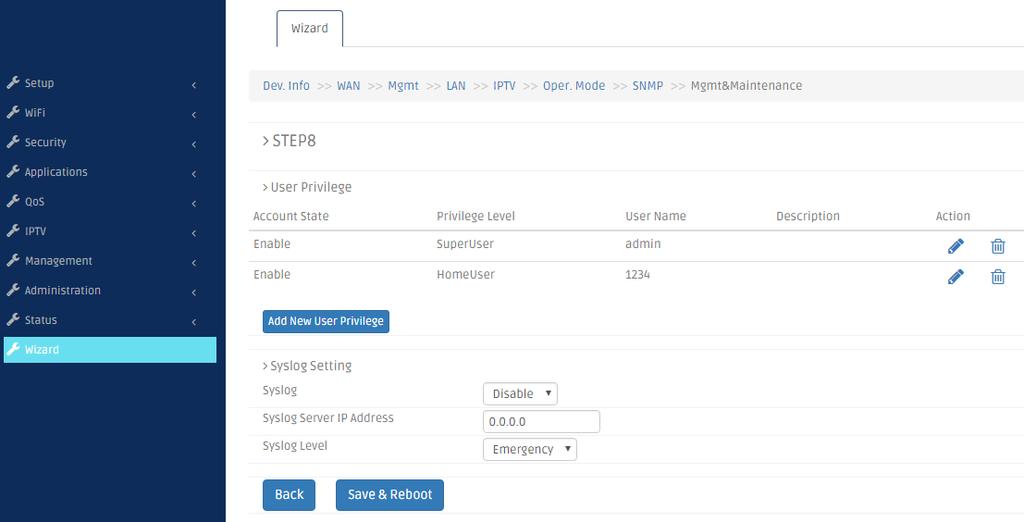
170 170
171 4. SNMP NETWORK MANAGEMENT The Simple Network Management Protocol (SNMP) is an application-layer protocol that facilitates the exchange of management information between network devices. It is part of the TCP/IP protocol suite. SNMP enables network administrators to manage network performance, find and solve network problems, and plan for network growth. SNMP consists of the following key components: Managed device is a network node that contains SNMP agent. Managed devices collect and store management information and make this information available to NMS using SNMP. Managed devices can be switches/hub, etc. MIB (Management Information Base) defines the complete manageable entries of the managed device. These MIB entries can be either read-only or read-write. For example, the System Version is read-only variables. The Port State Enable or Disable is a read-write variable and a network administrator can not only read but also set its value remotely. SNMP Agent is a management module resides in the managed device that responds to the SNMP Manager request. SNMP Manager/NMS executes applications that monitor and control managed devices. NMS provide the bulk of the processing and memory resources required for the complete network management. SNMP Manager is often composed by desktop computer/work station and software program such as HP OpenView. Totally, 4 types of operations are used between SNMP Agent & Manager to change MIB information. These 4 operations all use the UDP/IP protocol to exchange packets. GET: This command is used by an SNMP Manager to monitor managed devices. The SNMP Manager examines different variables that are maintained by managed devices. GET Next: This command provides traversal operation and is used by the SNMP Manager to sequentially gather information in variable tables, such as a routing table. SET: This command is used by an SNMP Manager to control managed devices. The NMS changes the values of variables stored within managed devices. Trap: Trap is used by the managed device to report asynchronously a specified event to the SNMP Manager. When certain types of events occur, a managed device will send a trap to alert the SNMP Manager. The system built-in management module also supports SNMP management. Users must install the MIB file before using the SNMP based network management system. The MIB file is on a disc or diskette that accompanies the system. The file name extension is.mib, which SNMP based compiler can read. Please refer to the appropriate documentation for the instructions of installing the system private MIB. 171

172 APPENDIX A: Set Up DHCP Auto-Provisioning Networking devices, such as switches or gateways, with DHCP Auto-provisioning function allow you to automatically upgrade firmware and configuration at startup process. Before setting up DHCP Server for auto-upgrade of firmware and configuration, please make sure the Residential Gateway that you purchased supports DHCP Auto-provisioning. Setup procedures and autoprovisioning process are described below for your reference. A. Setup Procedures Step 1. Setup Environment DHCP Auto-provisioning-enabled products that you purchased support the DHCP option 60 to work as a DHCP client. The system includes ISC DHCP server, File server (TFTP or FTP) and the Residential Gateway. 172
173 You can find this file in Linux ISC DHCP server. /usr/local/etc/dhcpd.conf Step 2. Prepare dhcpd.conf file Step 3. Copy the marked text to dhcpd.conf A sample of dhcp text is provided in Appendix B. Please copy the marked area to dhcpd.conf file. Copy the text to dhcpd.conf file Sample dhcp text 173
. 3. Specify the FTP or TFTP IP address. 4. Login FTP server anonymously. 5. Specify FTP Server login name. 6.")
174 Step 4. Modify dhcpd.conf file Modify the marked area with your own settings. 1. This value is configurable and can be defined by users. 2. Specify the protocol used (Protocol 1: FTP; Protocol 0: TFTP). 3. Specify the FTP or TFTP IP address. 4. Login FTP server anonymously. 5. Specify FTP Server login name. 6. Specify FTP Server login password. 7. Specify the product model name. 8. Specify the firmware filename. 9. Specify the MD5 for firmware image. The format of MD5 might be the same as the one in the sample text. 10. Specify the configuration image filename. 174
175 Step 5. Generate a Configuration File Before preparing the configuration image in TFTP/FTP Server, please make sure the device generating the configuration image is set to Get IP address from DHCP assignment. This is because that DHCP Auto-provisioning is running under DHCP mode, so if the configuration image is uploaded by the network type other than DHCP mode, the downloaded configuration image has no chance to be equal to DHCP when provisioning, and it results in MD5 never match and causes the device to reboot endlessly. In order for your Residential Gateway to retrieve the correct configuration image in TFTP/FTP Server, please use the following rule to define the configuration image s filename. The filename should contain the configuration image filename specified in dhcpd.conf followed by the last three octets of your device s MAC address. For example, if the configuration image s filename specified in dhcpd.conf is metafile and the MAC address of your device is 00:06:19:03:21:80, the configuration image filename should be named to metafile dat. Step 6. Place a copy of Firmware and Configuration File in TFTP/FTP Server The TFTP/FTP File server should include the following items: 1. Firmware image 2. Configuration image 3. User account for your device (For FTP server only) 175

176 B. Auto-Provisioning Process This Residential Gateway is setting-free (through auto-upgrade and configuration) and its upgrade procedures are as follows: 1. The ISC DHCP server will recognize the device whenever it sends an IP address request to it. And ISC DHCP server will tell the device how to get a new firmware or configuration. 2. The device will compare the firmware and configuration MD5 code form of DHCP option every time when it communicates with DHCP server. 3. If MD5 code is different, the device will then upgrade the firmware or configuration. However, it will not be activated right after. 4. If the Urgency Bit is set, the device will be reset to activate the new firmware or configuration immediately. 5. The device will retry for 3 times if the file is incorrect, then it gives up until getting another DHCP ACK packet again. 176
FRG-3105 Series Residential Gateway
 FRG-3105 Series Residential Gateway Network Management User s Manual Version 0.90 1 Trademarks Contents are subject to revision without prior notice. All other trademarks remain the property of their respective
HES-3106 SERIES 6 PORTS 10/100/1000BASE-T ETHERNET MANAGED SWITCH
 HES-3106 SERIES 6 PORTS 10/100/1000BASE-T ETHERNET MANAGED SWITCH 5 PORTS 10/100/1000BASE-T ETHERNET MANAGED SWITCH WITH 1 PORT 1000BASE-X or 100/1000BASE-X UPLINK 5 PORTS 10/100/1000BASE-T ETHERNET MANAGED
EPS PoE+ ports 10/100/1000Mbps RJ combo uplink ports (10/100/1000 Mbps RJ-45 and 100/1000Mbps SFP slot) Managed Ethernet PoE Switch
 Managed Ethernet PoE Switch") EPS-3128 24 PoE+ ports 10/100/1000Mbps RJ-45 + 4 combo uplink ports (10/100/1000 Mbps RJ-45 and 100/1000Mbps SFP slot) Managed Ethernet PoE Switch Network Management User s Manual Version 0.90 1 Revision
EPS-3128 24 PoE+ ports 10/100/1000Mbps RJ-45 + 4 combo uplink ports (10/100/1000 Mbps RJ-45 and 100/1000Mbps SFP slot) Managed Ethernet PoE Switch Network Management User s Manual Version 0.90 1 Revision
IPS-3106 SERIES Managed Industrial PoE Ethernet Switch
 IPS-3106 SERIES Managed Industrial PoE Ethernet Switch Network Management User s Manual Version 0.96 1 Trademarks Contents are subject to revision without prior notice. All other trademarks remain the
HES-3109SSFP-DR. 8 ports 10/100/1000Mbps RJ port 100/1000Mbps SFP slot Uplink Managed Ethernet CPE Switch. Network Management.
 HES-3109SSFP-DR 8 ports 10/100/1000Mbps RJ45 + 1 port 100/1000Mbps SFP slot Uplink Managed Ethernet CPE Switch Network Management User s Manual Version 0.94 1 Revision History Version F/W Date Description
HES-3106SFP-F2 6-port L2+ Managed Gigabit Fiber Switch Network Management User s Manual Version 1.0
 HES-3106SFP-F2 6-port L2+ Managed Gigabit Fiber Switch Network Management User s Manual Version 1.0 1 Revision History Version F/W Date Description 1.0 0.99.0A 2018/11/09 First release 2 Trademarks CTS
HET-2106 SERIES. 5 ports 10/100Mbps RJ port 100Mbps fiber optics uplink Managed Ethernet CPE Switch. Network Management.
 HET-2106 SERIES 5 ports 10/100Mbps RJ-45 + 1 port 100Mbps fiber optics uplink Managed Ethernet CPE Switch Network Management User s Manual Version 0.97 1 Trademarks CTS is a registered trademark of Connection
FWRIII-2105 SERIES. 4 ports 10/100Mbps RJ-45; built-in IEEE802.11n WiFi and 1 port 100Mbps SFP slot uplink Residential Gateway. Residential Gateway
 FWRIII-2105 SERIES 4 ports 10/100Mbps RJ-45; built-in IEEE802.11n WiFi and 1 port 100Mbps SFP slot uplink Residential Gateway 4 ports 10/100Mbps RJ-45; built-in IEEE802.11n WiFi and 1 port 100Mbps SFP
HES-3109 SERIES 9 PORTS 10/100/1000BASE-T MANAGEMENT ETHERNET SWITCH
 HES-3109 SERIES 9 PORTS 10/100/1000BASE-T MANAGEMENT ETHERNET SWITCH 8 PORTS 10/100/1000BASE-T MANAGEMENT ETHERNET SWITCH WITH 1 PORT 1000BASE-X UPLINK OR 1 PORT 100/1000BASE-X UPLINK 8 PORTS 10/100/1000BASE-T
HES-3106-PLUS SERIES
 HES-3106-PLUS SERIES 5 PORTS 10/100/1000BASE-T ETHERNET MANAGED SWITCH WITH 1 PORT 1000BASE-X or 100/1000BASE-X UPLINK User s Guide Version 0.92 Trademarks CTS is a registered trademark of Connection Technology
icpe Gateway Controller
 icpe Gateway Controller Network Management User s Manual Version 0.90 1 Trademarks Contents are subject to revision without prior notice. All other trademarks remain the properties of their owners. Copyright
Security SSID Selection: Broadcast SSID:
 69 Security SSID Selection: Broadcast SSID: WMM: Encryption: Select the SSID that the security settings will apply to. If Disabled, then the device will not be broadcasting the SSID. Therefore it will
RANGER SERIES. 150Mbps Wireless Green Broadband Router DG-BR4000NG. 150 Mbps V
 RANGER SERIES 150Mbps Wireless Green Broadband Router DG-BR4000NG N 150 Mbps V1.2 2011-12-15 FCC warning: This equipment has been tested and found to comply with the limits for a class B digital device,
Wireless 11n Smart Repeater AP (1T1R)
") (1T1R) 2014 Table of Contents 1. Introduction...3 1.1 Package contents... 3 1.2 Product Features... 3 1.3 Front Panel Description... 4 1.4 Rear Panel Description... 5 2. Installation...6 2.1 Hardware Installation...
(1T1R) 2014 Table of Contents 1. Introduction...3 1.1 Package contents... 3 1.2 Product Features... 3 1.3 Front Panel Description... 4 1.4 Rear Panel Description... 5 2. Installation...6 2.1 Hardware Installation...
FWR-2105-WF-G SERIES FWR-2105-WF-N SERIES FWR-2105-WF-G-RF FWR-2105-WF-N-RF
 FWR-2105-WF-G SERIES 4 ports 10/100Mbps RJ-45, built-in IEEE 802.11b/g WiFi and 1 port 100Mbps fiber optics uplink Triple Play Gateway FWR-2105-WF-N SERIES 4 ports 10/100Mbps RJ-45, built-in IEEE 802.11
FRG-3105 Series Residential Gateway
 FRG-3105 Series Residential Gateway User s Guide Version 0.90 Revision History Version Date Description 0.90 20170605 First Release 2 Trademarks Contents are subject to revision without prior notice. All
AC1200M/MS. User Manual
 AC1200M/MS User Manual Table of Contents User Manual... 1 1 Preface... 1 2 LED Indicators and Connectors... 1 2.1 LED Indicators... 1 2.2 Hardware Installation... 2 3 Voice Prompt (AC1200MS)... 2 4 User
AC750 Wireless Dual-Band Router CR2. User Manual
 AC750 Wireless Dual-Band Router CR2 User Manual Version 1.0 4/25/2014 Table of Content Chapter 1 Introduction... 3 1.1 Features... 3 1.2 System Requirement... 3 1.3 Package Contents... 4 Chapter 2 Hardware
WRT300N-DD User Manual
 WRT300N-DD User Manual Contents Features... 3 Configuring the Router... 3 1 Operation Mode... 8 2 Internet Settings... 8 2.1 WAN... 9 2.2 LAN... 13 2.3 DHCP clients... 15 2.4 Advanced Routing... 15 2.5
Network Management. User s Manual. Version: 0.90
 MCT-RACK-12-MGM 12 SLOTS COMPACT MEDIA CONVERTER CENTER Network Management User s Manual Version: 0.90. Trademarks CTS is a registered trademark of Connection Technology Systems Inc.. Contents are subject
IPS-3110 Managed Industrial PoE Gigabit Ethernet Switch
 IPS-3110 Managed Industrial PoE Gigabit Ethernet Switch User s Guide Version 0.90 Trademarks Contents are subject to revision without prior notice. All other trademarks remain the property of their respective
Management Software AT-S79. User s Guide. For use with the AT-GS950/16 and AT-GS950/24 Smart Switches. Version Rev.
 Management Software AT-S79 User s Guide For use with the AT-GS950/16 and AT-GS950/24 Smart Switches Version 1.0.0 613-000207 Rev. A Copyright 2005 Allied Telesyn, Inc. All rights reserved. No part of this
CE APPROVED.4 INTRODUCTION.5 PACKAGE CONTENTS. 6 PRE - INSTALLATION CHECKLIST. 6 SYSTEM REQUIREMENTS. 6 FEATURES AND BENEFITS.11 SETUP WIZARD.
 Web Edition Dec. 2002 Contents CE APPROVED...4 INTRODUCTION...5 PACKAGE CONTENTS... 6 PRE - INSTALLATION CHECKLIST... 6 SYSTEM REQUIREMENTS... 6 FEATURES AND BENEFITS... 7 4 - PORT CABLE/XDSL ROUTER...9
Broadband Router User s Manual. Broadband Router User s Manual
 Broadband Router User s Manual Table of Contents 1 Introduction... 1 1.1 Features... 1 1.2 Package Contents... 2 1.3 LEDs & Connectors of Broadband Router... 2 1.4 System Requirements... 2 1.5 Installation
Light Mesh AP. User s Guide. 2009/2/20 v1.0 draft
 Light Mesh AP User s Guide 2009/2/20 v1.0 draft i FCC Certifications This equipment has been tested and found to comply with the limits for a Class B digital device, pursuant to Part 15 of the FCC Rules.
Wireless Router. Model: SR350N. User Manual V 1.1
 Wireless Router Model: SR350N User Manual V 1.1 CONTENTS 1.OVERVIEW... 3 1.1 ABOUT ADSL... 3 1.2 ABOUT ADSL2/2+... 3 1.3 FEATURES... 3 2 SPECIFICATION... 4 2.1 INTERFACE INTRODUCTION... 4 2.1.1 INDICATOR
SD24GS. 24-Port Web Smart Gigabit Ethernet Switch. User s Manual
 SD24GS 24-Port Web Smart Gigabit Ethernet Switch User s Manual FCC Warning This equipment has been tested and found to comply with the limits for a Class A digital device, pursuant to Part 15 of the FCC
User Guide TL-R470T+/TL-R480T REV9.0.2
 User Guide TL-R470T+/TL-R480T+ 1910012468 REV9.0.2 September 2018 CONTENTS About This Guide Intended Readers... 1 Conventions... 1 More Information... 1 Accessing the Router Overview... 3 Web Interface
The VWRT510&WRT500 High Speed Router User s Guide
 The VWRT510&WRT500 High Speed Router User s Guide The page 1 of 53 Table of Contents 1 Preface... 4 2 LED Indicators and Connectors... 5 2.1 LED Indicators... 6 2.2 Hardware Installation... 7 3 Voice Prompt...
LevelOne GES GE with 1 Combo SFP Web Smart Switch User Manual
 LevelOne GES-0852 8 GE with 1 Combo SFP Web Smart Switch User Manual Version 1.0-1109 1 FCC Certifications This Equipment has been tested and found to comply with the limits for a Class A digital device,
User Manual Gemtek WiMAX Modem
 User Manual Gemtek WiMAX Modem WIXS-177 CONTENTS Chapter 1 Overview...1-1 1.1. Indoor CPE... 1-1 1.2. Outdoor CPE... 1-2 Chapter 2 WEB-GUI...2-3 2.1. System Configuration Login... 2-3 2.2. System Logout...
ProSAFE 8-Port 10-Gigabit Web Managed Switch Model XS708Ev2 User Manual
 ProSAFE 8-Port 10-Gigabit Web Managed Switch Model XS708Ev2 User Manual April 2016 202-11656-01 350 East Plumeria Drive San Jose, CA 95134 USA Support Thank you for purchasing this NETGEAR product. You
User Manual. OT-1044ns
 User Manual OT-1044ns CONTENTS Chapter 1 Introduction... 3 1.1 Features... 3 1.2 Environments... 3 1.3 System Requirement... 4 Chapter 2 Hardware Installation... 4 2.1 Led indicators... 4 2.2 Back Panel
Figure 35: Active Directory Screen 6. Select the Group Policy tab, choose Default Domain Policy then click Edit.
 PC and Server Configuration Figure 35: Active Directory Screen 6. Select the Group Policy tab, choose Default Domain Policy then click Edit. Figure 36: Group Policy Tab 7. Select Computer Configuration
ProSAFE 8-Port and 16-Port 10-Gigabit Ethernet Web Managed Switch Models XS708Ev2 and XS716E User Manual
 ProSAFE 8-Port and 16-Port 10-Gigabit Ethernet Web Managed Switch Models XS708Ev2 and XS716E User Manual March 2017 202-11656-03 350 East Plumeria Drive San Jose, CA 95134 USA Support Thank you for purchasing
UIP1869V User Interface Guide
 UIP1869V User Interface Guide (Firmware version 0.1.8 and later) Table of Contents Opening the UIP1869V's Configuration Utility... 3 Connecting to Your Broadband Modem... 5 Setting up with DHCP... 5 Updating
TD-8616 ADSL2/2+ Ethernet Modem
 TD-8616 ADSL2/2+ Ethernet Modem Rev: 1.0.1 1910010001 COPYRIGHT & TRADEMARKS Specifications are subject to change without notice. is a registered trademark of TP-LINK TECHNOLOGIES CO., LTD. Other brands
WISNETWORKS. WisOS 11ac V /3/21. Software version WisOS 11ac
 WISNETWORKS User Manual V1.1 2016/3/21 Software version 1.0.0021 Table of contents 1. Setup& WMI... 3 1.1 Hardware Setup... 3 1.2 Web Management Interface... 3 2. Status... 4 2.1 Overview... 4 2.1.1 System...
User Manual. VDSL2 Router with 11n WiFi. Model:DV2211
 Model:DV2211 User Manual VDSL2 Router with 11n WiFi Model:DV2211 V33 User Manual 1 Model:DV2211 TABLE OF CONTENTS... 1 Device Installation... 4 Power on Router... 4 Factory Reset Button... 5 Network Connections...
AIRNET 54Mb b/g High Power USB Adapter. User s Manual
 AIRNET 54Mb 802.11b/g High Power USB Adapter User s Manual FCC Certifications Federal Communication Commission Interference Statement This equipment has been tested and found to comply with the limits
1. Package contents. 2. Connecting ADSL modem and wireless router
 1. Package contents WL-500W wireless router x 1 Power adapter x 1 Utility CD x 1 RJ45 cable x 1 Quick Start Guide x 1 2. Connecting ADSL modem and wireless router 1) Cable connection Wall power outlet
802.11a g Dual Band Wireless Access Point. User s Manual
 802.11a+802.11g Dual Band Wireless Access Point User s Manual 0 Chapter 1 Introduction 1.1 Feature Fully interoperable with IEEE 802.11b compliant products. High-Speed data transfer rate up to 11Mbps.
User Manual. AC ac Wireless Access Point/Router. Model WAC124. NETGEAR, Inc.
 AC2000 802.11ac Wireless Access Point/Router Model WAC124 December 2018 202-11885-02 NETGEAR, Inc. 350 E. Plumeria Drive San Jose, CA 95134, USA AC2000 802.11ac Support Thank you for purchasing this NETGEAR
Management Software AT-S101. User s Guide. For use with the AT-GS950/8POE Gigabit Ethernet WebSmart Switch. Version Rev.
 Management Software AT-S101 User s Guide For use with the AT-GS950/8POE Gigabit Ethernet WebSmart Switch Version 1.0.0 613-000985 Rev. A Copyright 2008 Allied Telesis, Inc. All rights reserved. No part
802.11b/g Access Point WL-8000AP
 802.11b/g Access Point WL-8000AP User s Guide - FCC Certifications This equipment has been tested and found to comply with the limits for a Class B digital device, pursuant to Part 15 of the FCC Rules.
Calix T07xG HGU ONT Operation and Maintenance Guide
 Calix T07xG HGU ONT Operation and Maintenance Guide July 2013 #220-00589, Rev 10 Contents About This Document... 5 Revision History... 6 Product Introduction... 7 Chapter 1: ONT Configuration... 11 Web
Section 3 - Configuration. Enable Auto Channel Scan:
 Enable Auto Channel Scan: Wireless Channel: The Auto Channel Scan setting can be selected to allow the DGL-4500 to choose the channel with the least amount of interference. Indicates the channel setting
300M Wireless-N Broadband Router User Manual
 300M Wireless-N Broadband Router Model No.: ib-wrb314n User Manual Ver.: 1.0.0 Contents...Error! Bookmark not defined. Chapter 1 Product Overview... 3 Package Contents 3 Conventions....4 Panel Overview...
VERTICAL HORIZON VH-2402S FAST ETHERNET SWITCH MANAGEMENT GUIDE
 VERTICAL HORIZON VH-2402S FAST ETHERNET SWITCH MANAGEMENT GUIDE 9033645-01 Notice Only qualified personnel should perform installation procedures. NOTICE Enterasys Networks reserves the right to make
WL-5420AP. User s Guide
 WL-5420AP User s Guide Table of contents INTRODUCTION... 1 About the Operation Modes...2 LED Indicators...5 Solid...5 Ports on the Rear Panel...7 GETTING CONNECTED... 8 WPA AP -CONFIGURATION VIA WEB...
Wireless a CPE User Manual
 NOTICE Changes or modifications to the equipment, which are not approved by the party responsible for compliance, could affect the user's authority to operate the equipment. Company has an on-going policy
TEW-211BRP. Wireless AP Router. User s Manual
 TEW-211BRP Wireless AP Router User s Manual Version 1.4 - Jan 2002 CONTENTS Introduction...3 Hardware Installation...5 General Wireless AP Router System Connection...6 Wireless AP Router Default Settings
EnGenius EAP N Multi-Function AP/Repeater
 EnGenius EAP9550 11N Multi-Function AP/Repeater Table of Content 1. Introduction...4 1.1. Features and Benefits...4 1.2. Package Contents...5 1.3. System Requirement...5 2. Understanding the Hardware...6
Wireless-G Router User s Guide
 Wireless-G Router User s Guide 1 Table of Contents Chapter 1: Introduction Installing Your Router System Requirements Installation Instructions Chapter 2: Preparing Your Network Preparing Your Network
APC-100. IEEE g Wireless USB Adapter. User s Guide v1.0
 APC-100 IEEE 802.11g Wireless USB Adapter User s Guide v1.0 FCC Certifications Federal Communication Commission Interference Statement This equipment has been tested and found to comply with the limits
Peplink SD Switch User Manual. Published on October 25th, 2018
 Peplink SD Switch User Manual Published on October 25th, 2018 1 Table of Contents Switch Layout 4 Specifications 5 Hardware Overview 6 Quick Start Functions 7 Reset Switch 7 Connect Ethernet 7 Connect
Configuration Guide TL-ER5120/TL-ER6020/TL-ER REV3.0.0
 Configuration Guide TL-ER5120/TL-ER6020/TL-ER6120 1910012186 REV3.0.0 June 2017 CONTENTS About This Guide Intended Readers... 1 Conventions... 1 More Information... 1 Viewing Status Information... 2 System
IP806GA/GB Wireless ADSL Router
 IP806GA/GB Wireless ADSL Router 802.11g/802.11b Wireless Access Point ADSL Modem NAT Router 4-Port Switching Hub User's Guide DECLARATION OF CON FORMITY This device complies with Part 15 of the FCC Rules.
Contents Introduction to the Product Configuration CPE built-in Web Server Access CPE Setup on the web page Trouble Shooting Operating Information
 Contents Introduction to the Product Functional Features LED Information Rear Side Information Configuration Network Configuration Package Configuration PC Configuration(Windows XP) How to check your IP
WL580E. DUAL BAND WALL PLUGGED 300Mbps WIRELESS-N REPEATER
 WL580E DUAL BAND WALL PLUGGED 300Mbps WIRELESS-N REPEATER Copyright 2014 All rights reserved. No part of this document may be reproduced, republished, or retransmitted in any form or by any means whatsoever,
DWR G Integrated Access Device. User Manual
 DWR-923 4G Integrated Access Device User Manual TABLE OF CONTENTS 1. GETTING TO KNOW THE DWR-923... 2 1.1 Introduction... 2 1.2 Package Contents... 3 1.3 System Requirements... 3 1.4 Hardware Overview
CHAPTER 7 ADVANCED ADMINISTRATION PC
 ii Table of Contents CHAPTER 1 INTRODUCTION... 1 Broadband ADSL Router Features... 1 Package Contents... 3 Physical Details... 4 CHAPTER 2 INSTALLATION... 6 Requirements... 6 Procedure... 6 CHAPTER 3 SETUP...
IEEE g Wireless PC Card. User s Guide
 IEEE 802.11g Wireless PC Card User s Guide FCC Certifications Federal Communication Commission Interference Statement This equipment has been tested and found to comply with the limits for a Class B digital
TABLE OF CONTENTS COPYRIGHT INTRODUCTION...3 PRODUCT OVERVIEW...3 COMPONENTS AND FEATURES...3 HARDWARE INSTALLATION
 TABLE OF CONTENTS COPYRIGHT...2 1. INTRODUCTION...3 PRODUCT OVERVIEW...3 COMPONENTS AND FEATURES...3 HARDWARE INSTALLATION...3 2. MFP SERVER INSTALLATION...5 PREPARATION...5 CONFIGURATION SOLUTION TABLE...5
MANUAL NWAC7000. Wireless Management Platform
 MANUAL NWAC7000 Wireless Management Platform Contents Chapter 1 Manual Introduction... 4 Chapter 2:Product Introduction... 4 2.1 Products description... 4 2.2 Products Properties... 4 2.2.1Hardware Property...
Longshine Technologie Europe GmbH
 Longshine Technologie Europe GmbH www.longshine.de TABLE OF CONTENTS COPYRIGHT...2 1. INTRODUCTION...3 PRODUCT OVERVIEW...3 COMPONENTS AND FEATURES...3 HARDWARE INSTALLATION...3 2. MFP SERVER INSTALLATION...5
LevelOne. User Manual. WAP Mbps PoE Wireless AP V3.0.0
 LevelOne WAP-0005 108Mbps PoE Wireless AP User Manual V3.0.0 i TABLE OF CONTENTS CHAPTER 1 INTRODUCTION... 1 FIGURE 1: WIRELESS ACCESS POINT... 1 FEATURES OF YOUR WIRELESS ACCESS POINT... 1 Security Features...
User Manual. Wireless-N ADSL2+ Modem Router
 User Manual Wireless-N ADSL2+ Modem Router Table of Contents 1. ABOUT THIS GUIDE...3 1.1 Navigation of the User s Guide... 3 2. PRODUCT OVERVIEW...3 2.1 Introduction... 3 2.2 Features... 3 2.3 Panel Layout...
WHG311 V1.03. Secure WLAN Controller
 WHG311 V1.03 Secure WLAN Controller Copyright Notice This document is protected by USA copyright laws and other laws and is the property of 4IPNET, INC. You may not copy, reproduce, distribute, publish,
AplombTech Smart Router Manual
 AplombTech Smart Router Manual (Version: 1.0) 1 Version & Purpose Version Manual version V 1.0 Explanation Corresponds to the initial version of device Purpose This manual describes the function features
48-Port Gigabit Ethernet Smart Managed Plus Switch User Manual
 48-Port Gigabit Ethernet Smart Managed Plus Switch User Manual Model GS750E July 2017 202-11784-01 350 E. Plumeria Drive San Jose, CA 95134 USA Support Thank you for purchasing this NETGEAR product. You
Wireless-B Broadband Router
 Wireless-B Broadband Router Version 1.0 Trademarks Microsoft, Windows, and Windows NT are registered trademarks of Microsoft Corporation. Other brand and product names are registered trademarks or trademarks
CTS-iCPE Gateway Controller User s Manual Version: Revision B1
 CTS-iCPE Gateway Controller User s Manual Version: Revision B1 Trademarks Contents are subject to revision without prior notice. All other trademarks remain the property of their respective owners. Copyright
GIoT Femto Cell User Guide
 Document Number Creat ed By Eric GIoT Femto Cell User Guide Modification History Dat e Change log Aut hor Revision 2017/ 3/ 23 1st version Eric, Joey 001 This GIoT Femto Cell User Guide will assist you
LevelOne User Manual WNC-0600USB N_One Wireless USB Adapter
 LevelOne User Manual WNC-0600USB N_One Wireless USB Adapter V2.0.0-0712 i Safety FCC WARNING This equipment has been tested and found to comply with the limits for a Class B digital device, pursuant to
IN-16POEGWM. User Manual. 16 Port Gigabit Ethernet + 4 Combo Gigabit SFP PoE Web Smart Switch
 IN-16POEGWM User Manual 16 Port Gigabit Ethernet + 4 Combo Gigabit SFP PoE Web Smart Switch FCC Warning This Equipment has been tested and found to comply with the limits for a Class-A digital device,
Wireless b/g/n 150Mbps AP Router
 Wireless 802.11b/g/n 150Mbps AP Router User Manual V1.2 2009-11-30 Package Contents The following items should be found in your package: One Wireless 802.11b/g/n 150Mbps Broadband Router One DC 9v power
2. PRINT SERVER INSTALLATION...
 TABLE OF CONTENTS COPYRIGHT...2 1. INTRODUCTION...3 PRODUCT OVERVIEW...3 COMPONENTS AND FEATURES...3 HARDWARE INSTALLATION...4 NETWORK ENVIRONMENT...5 2. PRINT SERVER INSTALLATION...6 PREPARATION...6 CONFIGURATION
MARQUE : REFERENCE : CODIC : NETGEAR GSS108E-100EUS NOTICE
 MARQUE : REFERENCE : CODIC : NETGEAR GSS108E-100EUS 4254961 NOTICE ProSAFE 8-Port and 16-Port Gigabit Web Managed Click Switch Model GSS108E and GSS116E User Manual May 2016 202-11520-03 350 East Plumeria
16-SLOT IN-BAND MANAGEMENT CHASSIS
 FCM-CHS2-XX 16-SLOT IN-BAND MANAGEMENT CHASSIS Network Management Manual Version 2.2 1 FCC Warning This equipment has been tested and found to comply with the limits for a Class A digital device, pursuant
V7610-I1. User Manual
 V7610-I1 User Manual Contents 1. Introduction... 4 1.1 Specifications... 4 2. Installation... 5 2.1 Hardware installation... 5 3. Connect to the router... 6 3.1 Setup your local network... 6 3.2 Connect
ZyWALL 10W. Internet Security Gateway. Quick Start Guide Version 3.62 December 2003
 Internet Security Gateway Quick Start Guide Version 3.62 December 2003 Introducing the ZyWALL The is the ideal secure gateway for all data passing between the Internet and the LAN. By integrating NAT,
Outdoor Wireless USB Adapter User Guide
 Outdoor Wireless USB Adapter User Guide FCC STATEMENT This equipment has been tested and found to comply with the limits for a Class B digital device, pursuant to part 15 of the FCC Rules. These limits
RX3041. User's Manual
 RX3041 User's Manual Table of Contents 1 Introduction... 2 1.1 Features and Benefits... 3 1.2 Package Contents... 3 1.3 Finding Your Way Around... 4 1.4 System Requirements... 6 1.5 Installation Instruction...
SWP-0208G, 8+2SFP. 8-Port Gigabit Web Smart Switch. User s Manual
 SWP-0208G 1 SWP-0208G, 8+2SFP 8-Port Gigabit Web Smart Switch User s Manual Version: 3.4 April 1, 2008 2 TABLE OF CONTENT 1.0 INTRODUCTION...4 1.1 MAIN FEATURES...4 1.2 START TO MANAGE THIS SWITCH...6
Gigaset Router / en / A31008-E105-B / cover_front_router.fm / s Be inspired
 s Be inspired Table of Contents Table of Contents Safety precautions........................... 3 The Gigaset Router........................... 3 Features and Benefits..................................................
ProSAFE Easy-Mount 8-Port Gigabit Ethernet PoE+ Web Managed Switch
 ProSAFE Easy-Mount 8-Port Gigabit Ethernet PoE+ Web Managed Switch Model GS408EPP User Manual December 2016 202-11693-01 350 East Plumeria Drive San Jose, CA 95134 USA Support Thank you for purchasing
AirCruiser G Wireless Router GN-BR01G
 AirCruiser G Wireless Router GN-BR01G User s Guide i Contents Chapter 1 Introduction... 1 Overview...1 Features...1 Package Contents...2 AirCruiser G Wireless Router Rear Panel...2 AirCruiser G Wireless
CVT-2512 SERIES CVT-3512 SERIES
 CVT-2512 SERIES 10/100BASE-TX to 100BASE-FX Standalone Managed Media Converter with 802.3ah OAM compliance CVT-3512 SERIES 10/100/1000BASE-T to 1000BASE-X Standalone Managed Media Converter with 802.3ah
Grandstream Networks, Inc.
 Grandstream Networks, Inc. GWN7000 Enterprise Router & Access Point Manager COPYRIGHT 2016 Grandstream Networks, Inc. http://www.grandstream.com All rights reserved. Information in this document is subject
WUG2690 User s Manual
 802.11b+g Wireless LAN USB Adapter WUG2690 User s Manual Federal Communication Commission Interference Statement This equipment has been tested and found to comply with the limits for a Class B digital
FCN-3112 Series. 10/100/1000TX to 1000SX SNMP Managed Media Converter. Version 1.0 User Manual
 FCN-3112 Series 10/100/1000TX to 1000SX SNMP Managed Media Converter Version 1.0 User Manual Copyright 2018 Antaira Technologies, LLC. All Rights Reserved This document contains information, which is protected
IEEE n Wireless PCI Adapter. User s Manual
 IEEE 802.11n Wireless PCI Adapter User s Manual October, 2008 FCC Warning This equipment has been tested and found to comply with the limits for a Class C digital device, pursuant to part 15 of the FCC
TABLE OF CONTENT 1. ABOUT THIS GUIDE Overview of the User s Guide INTRODUCTION Overview Features...
 TABLE OF CONTENT 1. ABOUT THIS GUIDE... 3 1.1 Overview of the User s Guide... 3 2. INTRODUCTION... 3 2.1 Overview... 3 2.2 Features... 3 2.3 Panel Layout... 4 2.3.1 Front Panel... 4 2.3.2 Rear Panel...
Wireless-N Broadband AP / Router. User s Manual. Version 1.3
 Wireless-N Broadband AP / Router User s Manual Version 1.3 Federal Communication Commission Interference Statement This equipment has been tested and found to comply with the limits for a Class B digital
802.11N Wireless Broadband Router
 802.11N Wireless Broadband Router Pre-N Wireless Access Point Broadband Internet Access WPS 4-Port Switching Hub User's Guide Table of Contents CHAPTER 1 INTRODUCTION... 1 Wireless Router Features... 1
Broadband Router DC-202. User's Guide
 Broadband Router DC-202 User's Guide Table of Contents CHAPTER 1 INTRODUCTION... 1 Broadband Router Features... 1 Package Contents... 3 Physical Details...3 CHAPTER 2 INSTALLATION... 5 Requirements...
Wireless Router. Model # R3000. User Guide v1
 Wireless Router Model # R3000 User Guide v1 Table of Contents Introduction 1 Minimum System Requirements 1 Features 1 Getting to Know the R3000 3 Performing a Quick Setup 7 Accessing Quick Setup Screens
LevelOne FBR User s Manual. 1W, 4L 10/100 Mbps ADSL Router. Ver
 LevelOne FBR-1416 1W, 4L 10/100 Mbps ADSL Router User s Manual Ver 1.00-0510 Table of Contents CHAPTER 1 INTRODUCTION... 1 FBR-1416 Features... 1 Package Contents... 3 Physical Details... 3 CHAPTER 2
User Manual. Rev:
 Default Login Details Login Address: www.mykasda.com Login Password: Set up by users Default Wi-Fi SSID: Kasda xxxx KW6516 (Printed on product label) Default Wi-Fi Password: 12345678 www.kasdanet.com Rev: