Ethernet - DMX8 MkII Range. User Guide - V4 rev3
|
|
|
- Emory Greene
- 6 years ago
- Views:
Transcription


1 User Guide - V4 rev3
2 User Guide - V4 rev3 Document lu_01_00037_3_man Copyright All rights reserved. No part of this documentation may be reproduced or transmitted in any form or by any means, electronic or mechanical, including photocopying and recording, without the prior written permission of Luminex. The information in this documentation is supplied without warranty of any kind, either directly or indirectly, and is subject to change without prior written notice. Luminex, its employees or appointed representatives will not be held responsible for any damages to software, hardware, or data, howsoever arising as a direct or indirect result of the product(s) mentioned herein. Issued by: Publications Department, Luminex LCE, Berkenlaan 8A, Hechtel - Eksel, B-3940, Belgium. Documentation reviewed April 22, 2015, by Bart Swinnen. Printed in the EU.
3 Table of Contents Warranty information...5 Limited warranty...5 Returning under warranty...5 Freight... 5 General... 6 Packaging... 6 Description... 6 Specification... 6 Dimensions...6 Weight... 7 Electrical... 7 Connectors... 7 Environmental...7 Connectivity... 8 Rear Panel Side Panel...8 Mains...8 DMX input / output... 9 Interface Front panel Ethernet port...10 DMX input / output...10 Status indication...11 Status indication...11 Front end display information...11 Reset the node (Out of jail) Web interface Status Setup Node DMX Routing Merging Policies : Inputs (Local mode) Inputs (IP Merging)...21 Outputs (IP Merging)...21 Recover channel Network settings...26 IP Settings...26 Global DMX details Miscellaneous Toolbox...29 Profile manager Snapshot manager Firmware upgrade Toubleshooting Additional Documentation Credits:... 35
4
5 Warranty information Limited warranty Unless otherwise stated, your product is covered by a two (2) years parts and labor limited warranty. It is the owner s responsibility to furnish receipts or invoices for verification of purchase, date, and dealer or distributor. If purchase date cannot be provided, date of manufacture will be used to determine warranty period. Returning under warranty Any Product unit or parts returned to Luminex LCE must be packaged in a suitable manner to ensure the protection of such Product unit or parts, and such package shall be clearly and prominently marked to indicate that the package contains returned Product units or parts. Accompany all returned Product units or parts with a written explanation of the alleged problem or malfunction. Freight All shipping will be paid by the purchaser. Items under warranty shall have return shipping paid by the manufacturer only in the European Union. Under no circumstances will freight collect shipments be accepted. Prepaid shipping does not include rush expediting such as air freight. Air freight can be sent customer collect in the European Union. Warranty is void if the product is misused, damaged, modified in any way, or for unauthorized repairs or parts. Page 5 of 35
6 General Packaging - Ethernet-DMX8 MkII 1 x Ethernet DMX8 MkII 1 x User guide - Ethernet-DMX8/Truss MkII 1 x Ethernet DMX8 MkII Truss 1 x Powercon male connector 1 x User Guide Description The Ethernet-DMX8 MkII is an Ethernet node that serves 8 x DMX512 outlets, compatible with the following protocols: DMX512, DMX512-A, RDM (ANSI E1.20), sacn (ANSI E1.31) and Art-Net. All 8 outlets can be used as input or output. The Ethernet links are 100BaseTx connections on shielded Neutrik RJ45 Ethercon connectors. All configuration can be done over Ethernet through a built in website, or the front panel display. This all comes in a 19'' unit high metal housing for the Ethernet-DMX8 MkII. The Ethernet-DMX8/Truss MkII comes in a rugged truss mountable metal housing with two M10 inserts. This enclosure allows to use the node in a truss, on a wall or as a table top device. Specification Dimensions Ethernet-DMX8 MkII 482 x 183 x 44 (mm) 19 x 7,2 x 1,73 Package: 520 x 235 x 50 (mm) Ethernet-DMX8 MkII Truss 240 x 180 x 90 (mm) 9,44 x 7,08 x 3,54 Package: 310 x 260 x 110 (mm) Page 6 of 35
7 Weight Ethernet-DMX8 MkII: 2,3 kg Ethernet-DMX8/Truss MkII: 3,1 kg Electrical Ethernet-DMX8 MkII: Voltages: VAC Frequency: Hz Rated power: 20 W Fuse: 125V 250V, 1A, Slow blow only (5mm x 20mm) Ethernet-DMX8/Truss MkII: Voltages: VAC Frequency: Hz Rated power: 20 W Fuse: 250V 1A, Slow blow Connectors 2 x shielded Neutrik RJ45 Ethercon connector (front and rear for Ethernet-DMX8 MkII, front and side for EthernetDMX8 MkII Truss) 8 x shielded Neutrik gold plated 5 pin XLR (female) 8 x optic and galvanic isolated DMX port 1 x IEC inlet with fuse holder (Rack version only) 1 x Neutrik Powercon inlet (Truss version only) Environmental Operating temperature: 0 ~ 60 C (32 ~ 140 F) Storage temperature : -10 ~ 70 C (14 ~ 158 F) Humidity: 5-95% non condensing Page 7 of 35


8 Connectivity Rear Panel Side Panel IEC Inlet Punched Holes Fuse holder Powercon socket DMX connectors 10/100Mbps Ethernet ports Mains Ethernet-DMX8 MkII The device operates with an AC voltage between 90V and 260V within a frequency range of 47Hz and 63Hz. An IEC socket is located at the rear of the unit. Please use an IEC plug compliant cable to feed power to the unit. Luminex recommend the use of a power cable, fitted with an IEC-Lock plug. The IEC-Lock system offers a reliable way to connect the power cable to the unit.!!! This equipment must be earthed!!! Punched holes The unit offers 8 punched holes to easily install 8 optional DMX input connectors, or to reverse the board. Ethernet 1 Neutrik RJ45 Ethercon is provided as Ethernet link. Page 8 of 35
9 Ethernet-DMX8 MkII Truss The device operates with an AC voltage between 100V and 240V within a frequency range of 50Hz and 60Hz. A Neutrik PowerCon IN connector can be connected to the device. Please use an authorized plug and connect the cores in the mains lead in accordance with the following scheme: Green / Yellow: Earth Blue: Neutral Brown: Live!!! This equipment must be earthed!!! Ethernet 1 Neutrik RJ45 Ethercon is provided as Ethernet link. DMX input / output 8 shielded Neutrik 5 pin gold plated female connectors are provided as outlet (input or output). All DMX outlets are optic and galvanic isolated. See detailed pinout on page 11. Page 9 of 35
10 Interface Front panel Graphical LCD Display And Jog DMX ports: bi-directional Shielded Gold plated XLR 5 pins Neutrik connectors 10/100MBps Ethernet port LED indication of network activity and link. Power Ok LED. Ethernet-DMX8 MkII The front panel interface is provided with 1 graphical LCD display, 1 jog, 1 Ethernet port, 8 DMX outlets and 3 indication LEDs. Standard DMX port routing and advanced features like merging, backup, etc can be configured from the front end LCD display, from the built in Web interface or through LumiNet Monitor V2 Software. Ethernet port 1 Neutrik RJ45 Ethercon is provided as Ethernet link. DMX input / output 8 shielded Neutrik 5 pin gold plated female connectors are provided as outlet (input or output). All DMX outlets are optic and galvanic isolated. Page 10 of 35
11 Connector Pin 1 Pin 2 Pin 3 Pin 4 Pin 5 Function Signal common (0 volt) Data complement (-) Data true (+) Not used Not used All outlets are compliant with the DMX512-A timing specification and are terminated and rebiased. Status indication 3 LEDs are provided to indicate Network link and activity (Ethernet ports 1&2), and power Ok. Ethernet-DMX8/Truss MkII Status indication 3 LEDs are provided to indicate Network link and activity (Ethernet ports 1&2), and power Ok. The front panel interface is provided with 1 graphical LCD display and 1 jog. Standard DMX port routing and advanced features like merging, backup, etc can be configured from the front end LCD display, from the built in Web interface or through LumiNet Monitor V2 Software. Front end display information Four indication screens will rotate continuously on the display with an interval of a few seconds. Page 11 of 35
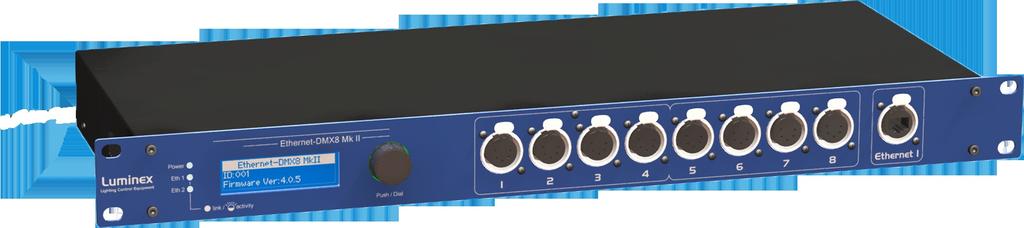
12 Screen 1 Model and firmware version This screen informs you on the type of model of Ethernet-DMX8 MkII you're using. It gives also the ID number, and the firmware version the node is actually running. Screen 2 Network settings These two screens display all the information of the two virtual nodes the Ethernet-DMX8 embeds. Each node have a short name entered through the Web interface. The screens give also the complete network setting information, such as IP address and netmask of each node. Screen 3 Model and firmware version This screen gives a complete overview of the DMX ports settings: the second raw gives information on the direction set on each port. The third raw informs you on the mode set on each outlet. Regarding the direction, differents letters will appear to show the mode set on the outlet : N (Normal), H (HTP merge), L (LTP merge), C (Custom), B (Backup), M(Merge), Z (Zero). A - means either the outlet is disable, either the outlet is set as an output, but no Art-Net data have been detected with the related universe. See page 16 for the explanation of each available mode. Page 12 of 35
13 Unlock the node When the node is password protected through the Web interface, it will automatically lock the access to the Web interface. To unlock the node, enter the password in the password field (login = admin). Reset the node (Out of jail) This useful function makes it possible to bring the node in a factory default. 1. Press and hold the jog on the front panel 2. Power up the device 3. wait until the converter to display the reset confirmation 4. confirm 5. The unit is now rebooting to its default settings Page 13 of 35
, which shows all Luminex nodes on the")
14 Web interface Status The complete device can be configured from an intuitive Web interface. You just have to browse to the IP address of the unit. If you do not know the IP address, you can quickly discover it through the front end display or by running Luminet Monitor V2 software (free downloadable tool), which shows all Luminex nodes on the network. Make sure that the computer, you use to browse, is setup in the correct network address range (IP 2.x.x.x or 10.x.x.x and subnet ). When you're not using a complete network setup (Ethernet switches, hubs, routers, WLAN,...), you can also use either a cross Ethernet cable or straight Ethernet cable to directly connect the unit to your computer. After all connections and setup on the computer are completed, open your favorite web browser (we recommend Firefox) and enter the IP address you want to reach in the URL field : Actual DMX routing Actual Global settings Actual Network settings Navigation Bar You'll end up at the status page of the device. This page has a complete overview of the device settings. The overview shows the actual DMX and network setting / routing of the complete device. The Web interface offers several languages. Select the language that fits your needs in the drop down menu located on the top right side of the Web page. Page 14 of 35
15 Setup Choose one of the items in the sub menu to setup the device. Once in a setup page, help is available on almost every field title. Just click on the question mark next to the topic. A pop up frame will display the overall information of each term displayed on the Web interface. Node To setup the node click on the appropriate sub menu item in the Setup navigation bar (Node). This is the main settings page. You can setup every single outlet of the node, as input or output. Select the outlet's direction, mode, protocol and universe, enable/disable RDM traffic. Here you can also change the IP address, Netmask, port and the Art-Net short and long name indication. Node 1 link will lead you to outlets 1 to 4 configuration. Node 2 link will lead you to outlets 5 to 8 configuration page. Page 15 of 35
16 DMX Routing To better understand the use of all features, let's define each category of this menu: Direction : Set the direction you need to the outlet, either Input or Output. Depending your selection, some features won't be available in the other categories. Protocol : Determines the network protocol used for the outlet (Art-Net or streaming over ACN (sacn E1.31)) Universe : ArtNet: Select one of 256 possible universes available in the Art-Net protocol. This is used for addressing DMX lines on Art-Net. The hexadecimal value of the universe is in between brackets. The first digit equals to the Art-Net subnet and the second to the Art-Net universe within that subnet. sacn : Select the sacn universe to use for addressing DMX lines on sacn. You can enter a numeric value between 1 and In case of an input, the priority of the universe can be set by adding a colon and the priority value. The priority level can go from 0 to 200. A higher level has a higher priority. (ex: 678:100 means universe 678 at priority level 100) Mode : According to the direction you set on the outlet, this menu offers several mode : Input : Disabled : Outlet is disabled, better for node performance. Normal : Outlet set as normal input Merge : Allow to merge 2 DMX streams. When outlet 1 is configured as a merged input, the next outlet (2) will be automatically set as input as well. Output : Disabled : Outlet is disabled, better for node performance. Zero : Send all channels with a zero value (for maintenance only) Normal: Normal output. IP Merging : This special feature allows you to merge up to 4 different Art-Net or sacn streams through the network. The merging policy will be mainly applied on the Output, except for IP backup. Legend : Set a legend to the outlet, useful to remind yourself what's connected to that outlet. Unicast : Art-Net is a broadcast protocol, which means that each packet sent from a single source will be received by all actives equipment on the network. Unicast allows you to cast you data to a selected IP address, resulting in a better use of network bandwidth. Page 16 of 35
. AD will continuously check for new and disappeared RDM devices on the output.")
17 RDM : Enable / disable RDM. Enabling RDM allows RDM traffic to be transported from/to outlet over the network and back. The nodes will act as an unmanaged proxy device. When set as output it is also possible to enable Adaptive Discovery (AD). AD will continuously check for new and disappeared RDM devices on the output. Once RDM is activated, you'll notice a cross in the status page. Click on this cross to see the list of discovered RDM devices (Illustration 1) attached to the node. Illustration 1:Discovered RDM devices All setting that are not applicable for the actual setting will be grayed out or marked as N/A (Not Applicable). Page 17 of 35
.")
18 Merging Policies : The Ethernet-DMX8 MkII firmware offers enhanced merging policies that fits to all kind of setup, even the most complex one! 4 available merging policies can be applied on your DMX network, in 2 main setup categories : Local merging : 2 different DMX streams are merged on the same physical device (Node). The merging policy will be mainly set on Inputs. Illustration 2: Local Merging IP Merging : This special feature allows you to merge up to 4 different ArtNet or sacn streams through the network. The merging policy will be mainly applied on the Output, except for IP backup. Available policies : HTP : Highest Take Precedence; Commonly used to merge dimmer channels. Up to 4 Art-Net or sacn sources can be merged. LTP : Latest Take Precedence; Better suited when using moving lights. Up to 4 Art-Net or sacn sources can be merged. Backup : Can be used either on input or output. When used on input, this policy allows you to add a backup DMX console on the second input. When used on a custom output, the policy allows you to add a backup Art-Net or sacn source on the network. Custom : This is the most complete and efficient policy. This mode offers you to choose what policy to apply for each channel of each universe, and also to create a complete custom soft patch. By more, the merging policy can be remotely triggered by DMX. Up to 2 DMX or Art-Net or sacn sources can merged thanks to that policy. The available policies differs if you use either inputs or outputs : Page 18 of 35
 2(02) In this example (left node of Illustration 2), the selected mode is Merge. The second outlet will automatically be set as a merged input.")
19 Inputs (Local mode) Outlet 1 Direction Input Outlet 2 Input Outlet 3 Input Outlet 4 Input Left node configuration Protocol ArtNet or sacn Universe 0(00) Mode Merge Ch1 HTP, LTP, Backup, Custom Disabled Disabled 1(01) 2(02) In this example (left node of Illustration 2), the selected mode is Merge. The second outlet will automatically be set as a merged input. You will not be able to configure a universe address for the second outlet, as the merged result will end at the universe address of the first outlet (primary input). Instead of universe you will be able to set the starting DMX channel address (1-512). This indicates from which channel address the second input has to be merged in. This offset is only available when using HTP or LTP policies. Those rules will be applied on all channel of the whole universe. If you choose Backup, a small blue icon will appears on the left side of Outlet 2 label; then click on it, a pop up frame appears : Illustration 3: DMX Input backup merging This menu lets you choose the backup time (from 400 to 9999ms). This time represents the delay from which the node will automatically switch to the backup outlet when invalid or no DMX is received anymore on the primary outlet. Tick the box if you want the node to auto-recover as soon as valid data is available again on primary connector. If you tick off the box, you will have to enable the trigger universe and select a recover channel (page 27). If you choose Custom policy, a small blue icon will also appear on the left side of Outlet 2 label; then click on it, a new pop up frame appears : Page 19 of 35

20 Illustration 4: Custom DMX input merging Click on Show Table button to see the complete soft patch available for this outlet. Offset S1 & S2 : Enter a value for the desired offset of the starting channel for outlets 1 or 2; example, for channels 1 to start on the third channel, enter 3. From To : this range let you quickly set the policy you need on the channel range of your choice. example, if you need HTP policy on channels 23 to 145, enter 23 in the From field and 145 in the To field. Then select the HTP policy in the Mode drop down list, then press Set Default Mode. Notice that following policies are available for each channel: Zero, HTP, LTP, S1 only (Source 1 only), S2 only (Source 2 only); S1 as Backup (Source 1 as backup), S2 as Backup (Source 2 as Backup). The left column represent the resulting universe channel number streamed to the network. S1 column represents Source 1 channels and S2 column Source 2 channels. It's thus easy to understand that you can create your own soft patch by entering the channels of your choice in one of theses column. Once your patch is created, click submit to close the window, then click submit again on the node page to record your settings. Page 20 of 35
 3(03) Disabled Disabled Disabled Disabled Right node configuration This mode can be very useful in such an application.")
21 Inputs (IP Merging) Direction Protocol Universe Mode Outlet 1 Output 1(01) Normal Outlet 2 Input Artnet or sacn Artnet or sacn IP Merging Disabled 1(01) Normal Backup Outlet 3 Outlet 3 Input Input 2(02) 3(03) Disabled Disabled Disabled Disabled Right node configuration This mode can be very useful in such an application. Illustration 5: IP Merging The right side lighting desk is used as a backup desk on stage. This means that the right side node will automatically switch to that outlet if no ArtNet or sacn packets are available on the selected universe (in that case universe 0). Select your backup time in the small pop up frame by clicking the left blue icon, then submit your changes. Outputs (IP Merging) Outlet 1 Direction Output Outlet 2 Outlet 3 Outlet 4 Input Input Input Protocol Universe Mode Normal 1(01) 2(02) 3(03) Disabled Disabled Disabled IP Merging HTP, LTP, Custom Disabled Disabled Disabled This mode can be very useful in the case of 2 control sources located in different places in the network wants to control the same DMX device at the same time. Page 21 of 35

22 Illustration 6: Output IP merging In this setup, the right lighting software (S2) is used in the same time as the left lighting desk (S1). Both streams are merged through the final output on the right node. The IP Merging mode provides the following policies when an outlet is set as output: HTP, for all outlet channels. Up to 4 Art-Net or sacn sources can be merged. LTP, for all outlet channels. Up to 4 Art-Net or sacn sources can be merged. Custom, to create a complete soft patch, to set merging policy for every single channel by IP source and to use the enhanced trigger system. Two Art-Net or sacn can be merged. If you choose Custom, click on the blue icon left sided to the Outlet label. A pop up frame appears: Page 22 of 35
.")
23 Illustration 7: DMX Output custom IP merging You can find in this pop up frame similar features as when using the custom merging on outlets set as inputs (page 19). The main difference is about the following points : Page 23 of 35
24 IP Source 1 & 2 : Here you can enter the 2 IP addresses assigned to your 2 control source. In case you don't know one of your source IP address, simply enter in the address field. Universe : Here you can select the universes number and the protocol streamed by your control sources. This feature is very useful if the 2 sources don't use the same universe number or protocol. Trigger channel. This feature allows you to remotely change the merging policy of one or several dedicated channels through a single DMX value. From anywhere on the network, you can by example swap from a LTP merge to a S2 only policy simply by using a different DMX trigger channel value. Enter here the DMX channel you want to use to remotely takeover control of the merging rule. Once you've selected that channel, you'll need to reach the Global web page of the node to enable and select your Trigger universe. You'll also need to patch or assign a DMX trigger channel to your control source; here is the DMX chart of the Luminex DMX trigger channel : 0-7 Do nothing 8-15 Zero out HTP merge LTP merge Source 1 only Source 2 only Reserved Source 1 as backup Source 2 as backup Do nothing Note :Never forget if you control the trigger channel from more than one source to press Do nothing once you've selected the desired value. Indeed, if you send 2 different values from 2 different sources for the trigger channel, the node won't stop swaping between those values, what results in a big slowing down of the node processing power. Recover channel If you have set one of a node outlet in IP backup mode, the node will swap automatically to this outlet in case of DMX failure from the primary source. Once the primary source is back again available, the node will automatically swap back to that source if set in Auto-recover mode. We all know that it can be useful to decide when to swap back to the primary source (booting time of the desk + loading the right cue in case of desk failure). Tick off the auto-recover box in the pop up window if you decide to work in manual recover mode. Then you'll have to enable the trigger universe in the Global Web page and choose a recover channel. You now have the opportunity to choose to recover either each outlet one by one or all outlet in one shot. Page 24 of 35
25 Here is the Luminex recover channel DMX chart : Value Outputs Merged Input pairs Normal Inputs Do nothing Recover Outlet 1 Recover Outlet 2 Recover Outlet 3 Recover Outlet 4 Recover Outlet 5 Recover Outlet 6 Recover Outlet 7 Recover Outlet 8 Recover all outlets Do Nothing Do Nothing Recover IP backup Recover DMX Backup Recover IP backup Recover DMX Backup Recover IP backup Recover DMX Backup Recover IP backup Recover DMX Backup Recover All Backup Do Nothing Do Nothing Recover IP backup Recover IP backup Recover IP backup Recover IP backup Recover IP backup Recover IP backup Recover IP backup Recover IP backup Recover all backup Do Nothing All those soft patches can be recorded or loaded from or to the node by using Load Patch or Export patch buttons. Luminex node recognize.txt files. These are TAB seperated files which can be edited using spreadsheet software (Excel, OO Calc,...) Page 25 of 35

26 Network settings IP Settings You can enter here the desired Art-Net IP address and Netmask you want to use. If you're not confident with Art-Net IP setting, tick the ArtNet compliant? box for the node to warn you in case of mistake. ArtNet IP addresses usually looks like 2.x.x.x or 10.x.x.x. You're not obliged to work with Art-Net IP addresses. If you wish to work with usual IT IP addresses as x.x, there's no problem for you to set such address on the node. Please remember that your node will thus not be visible on the network from devices set with conventional ArtNet IP addresses (2.x.x.x or 10.x.x.x). The Port field allows you to change the UDP port used on the network to transmit your UDP Art-Net packets. Luminex recommend no to change this value. Node identification : Enter here a small and long name to easily identify your node on the network through a Web interface, Art-Net compliant softwares or Luminex LumiNet monitor. Page 26 of 35

27 Global Some global settings can be altered by clicking Global in the Setup sub menu. Device Settings Here you can change the device's ID number which is indicated on LumiNet monitor. You can also enable the Trigger universe to remotely control your merging policy through any DMX source. The node will listen to the specified universe entered in the universe field. You can set your Recover channel if you use the manual recovery mode (page 19, 24). DMX details The DMX frame rate setting for all outlets. This can be set from 20 to 40 frames per second. Break Time can be set from 176 to 352µs. DMX Output time can be set to 1 10 minutes or continuously. This time sets how long an output remains outputting it's last DMX levels after no valid DMX packet came in for that particular universe on Art-Net or sacn. Page 27 of 35
28 Miscellaneous This part is about security and warnings : Verbose level : Select if you want to see error and warning messages on the front end LCD or through the Web interface. Lock Mode: select the security level you want to be applied on your Ethernet-DMX8 MkII front end. Auto lock will force the Node to lock the jog after 2 minutes of front end inactivity. Password protected mode will guide you to set a password into the locking code field. Once the node is locked, you'll have to enter the 4 digit password through the Web interface password field. Use admin in the login field. Page 28 of 35
29 Toolbox When clicking on Tools in the navigation bar, a sub menu appears. Choose one of the items in the sub menu. Profile manager The profile manager is able to store 40 profiles. All profiles are stored on the device. A preview of the complete configuration stored in a profile is shown when a profile is selected from the drop down list. When an empty profile is selected, no preview will be shown. Once a profile is selected you can choose to recall it, to save actual settings as a profile, or to delete the profile. Export profile Download link to save selected profile Import profile To upload a stored profile from PC or laptop When recalling a profile, an other page will appear to ask whether to recall your network settings as well or only the outlet routings. When saving a profile a next page will ask you to fill in a profile name. Page 29 of 35

30 Snapshot manager The Ethernet-DMX8 MkII embeds a snapshot function that allows you to capture 3 lighting states (fixed values) per outlet. The snapshot function is only available for outlets set as normal outputs. Auto load : When this option is ticked and the outlet is set as a normal output, then the unit will automatically load snapshot 1 at startup of the node. As soon Art-Net or sacn data arrives for that output, the DMX output will change. This feature is ideal for use in exhibition or expos. Capture : Captures actual output state as a static DMX snapshot when there is DMX running on the output. Simply press on one of the 3 captures available to snapshot the DMX output. Execute : Executes clicked snapshot and sets it on the DMX output when configured as a single output. The execute can't work if the associated universes runs on the network. Edit : Link to edit captured snapshot in a channel table (see following screenshot). Here you can directly edit and change channel values. You can also directly create your lighting state from that windows by inserting desired values, and recall the snapshot from the Web interface. Page 30 of 35

31 Capture recall The Ethernet-DMX8 MkII offers a user friendly interface for users to easily recall the recorded snapshots from the Web interface. Type the following address to reach the execute buttons page, where w.x.y.z represents the Ethernet-DMX8 MkII IP address : For instance: Page 31 of 35

32 Firmware upgrade The firmware upgrade page allows you to select a downloaded firmware file and upload it to the device. This page shows the actual firmware version running on the unit below the file upload field. The latest firmware file can always be downloaded from the Luminex web pages. To install the firmware on the Ethernet-DMX8 MkII follow these steps: 1. Download the.zip file and save it on your hard disk. 2. Extract the.zip file. 3. Please read the "ChangeNote.txt" for latest release changes. 4. Browse to the device its IP address with your favorite web browser. 5. Click Toolbox -> Firmware upgrade. 6. Browse to the extracted upgrade file on your hard disk (ethdmx8mkii_v4.x.x.bin), where X.X represents firmware version. 7. Select the file and press on the "Upgrade" button. 8. The upgrade file will be sent to the device. The following message appears on the front end display: Page 32 of 35
33 9. The unit will then reboot after the upgrade procedure and will display the following message on front end display: 10.Wait until the device has rebooted. (until then the Power/Ok LED will be blinking). A solid Power/Ok LED on indicates your EthernetDMX8 MkII has been properly updated. 11.Click now on Toolbox -> Firmware upgrade if the current version is set to the right version number. If the number is the same as mentioned with the file then the upgrade succeeded. Page 33 of 35
34 Toubleshooting The Power/OK LED is always blinking: You're Ethernet-DMX8 MkII doesn't boot properly. Restart the unit with the power switch. If this doesn't help, contact your local dealer. Please note the Power/OK LED will be blinking during upgrade procedure, don't switch off the power during this step. My computer is connected to the node, but the Link/Activity LED is still off. Check the Ethernet cable you're using, and check that each RJ45 on each side of the cable is properly inserted. Feel free to plug another cable to isolate the problem. I can't reach the Web interface of the Ethernet-DMX8 MkII Please check first the two previous steps. Then please be sure your computer is set in the same IP range than your Ethernet-DMX8 MkII. Try to ping the unit with a dedicated application, such as a DOS session on Windows, or a terminal session on MAC. You can use LumiNet Monitor V2 to discover your Ethernet-DMX8 MkII. If you can't see your device in LumiNet Monitor V2, please contact your local dealer. Page 34 of 35
35 Additional Documentation All additional documentation can be downloaded from our web pages in the support section. --> Support Credits: Art-Net is a trade mark of Alderamin Group Ltd. The Art-Net protocol and associated documentation is copyright Alderamin Group Ltd. Page 35 of 35
Ethernet - DMX4 MkII Range. User Guide - V4.x.x
 User Guide - V4.x.x Luminex Network Intelligence User Guide - V4.x.x Document lu_01_00030_4_man Copyright 2003-2017 Luminex Network Intelligence. All rights reserved. No part of this documentation may
Ethernet - DMX2 MkII Range. User Guide - V4.x.x
 User Guide - V4.x.x Luminex Network Intelligence User Guide - V4.x.x Document lu_01_00060_man Copyright 2003-2017 Luminex Network Intelligence. All rights reserved. No part of this documentation may be
Ethernet - DMX2 Box. User Guide - V3.0.0
 Ethernet - DMX2 Box User Guide - V3.0.0 LUMINEX Lighting Control Equipment Ethernet - DMX2 Box User Guide - V3.0.0 Document ethernet_dmx2b_user_guide_v3 Copyright 2003-2007 LUMINEX Lighting Control Equipment.
Ethernet - DMX8. User Guide V3.x.x
 Ethernet - DMX8 User Guide V3.x.x Ethernet - DMX8 User Guide V3.x.x Document eth-dmx8_web_man_v3_uk Copyright 2003-2009. All rights reserved. No part of this documentation may be reproduced or transmitted
GigaSwitch 8. User Guide
 GigaSwitch 8 User Guide GigaSwitch 8 User Guide Document lu_01_00016_4_man Copyright 2003-2011. All rights reserved. No part of this documentation may be reproduced or transmitted in any form or by any
DMX512-A 1.5 HUB. User Guide
 DMX512-A 1.5 HUB User Guide DMX512-A 1.5 HUB User Guide Document hub1.5_web_man_uk Copyright 2003-2008. All rights reserved. No part of this documentation may be reproduced or transmitted in any form or
DMX512-A 2.10 HUB. User Guide
 DMX512-A 2.10 HUB User Guide DMX512-A 2.10 HUB User Guide Document hub2.10_web_man_uk Copyright 2003-2008. All rights reserved. No part of this documentation may be reproduced or transmitted in any form
Ethernet - DinMX4. DIN Rail Ethernet <> DMX converter. Operating Manual V English
 Ethernet - DinMX4 DIN Rail Ethernet DMX converter Operating Manual V 4.1.6 English Table of Content Safety Instructions 3 Compliance information 4 Warranty information 5 In the box 5 Description 6 Specification
Safety Ring Switch. Front Plate Installation Guide
 Safety Ring Switch Front Plate Installation Guide Safety Ring Switch Front Plate Installation Guide Document srs_front-plate_inst_guide Copyright 2003-2008. All rights reserved. No part of this documentation
GigaCore 16Xt. Gigabit Ethernet Switch for the entertainment industry. Quick Start Guide. V2.1.0 Rev5. English
 GigaCore 16Xt Gigabit Ethernet Switch for the entertainment industry Quick Start Guide V2.1.0 Rev5 English Table of Content Safety Instructions 3 Compliance information 4 Warranty information 5 Registration
GigaCore 16RFO. Gigabit Ethernet Switch for the entertainment industry. Quick Start Guide. V2.1.0 Rev3. English
 GigaCore 16RFO Gigabit Ethernet Switch for the entertainment industry Quick Start Guide V2.1.0 Rev3 English Table of Content Safety Instructions 3 Compliance information 4 Warranty information 5 Registration
DOUG FLEENOR DESIGN. Model: NODE Ethernet to DMX512 Gateway OWNER'S MANUAL
 DOUG FLEENOR DESIGN (805) 481-9599 Model: NODE4 802.3 Ethernet to DMX512 Gateway OWNER'S MANUAL Doug Fleenor Design 396 Corbett Canyon Road Arroyo Grande, CA 93420 (805) 481-9599 Revision 2.0 January 2013
Safety Ring Switch. User Guide
 Safety Ring Switch User Guide Safety Ring Switch User Guide Document lu_01_00009_man Copyright 2003-2011. All rights reserved. No part of this documentation may be reproduced or transmitted in any form
DATAGATE MK2. Box Contents. Additional Features (licenses) Features. Safety
 Features. Safety") DATAGATE MK2 Box Contents Datagate Mk2 (pn: 70044) Straight connect Ethernet lead (pn:79102) IEC power cord (country dependent plug) This User manual Features 8 DMX ports isolated up to 1500V Gigabit Ethernet
DATAGATE MK2 Box Contents Datagate Mk2 (pn: 70044) Straight connect Ethernet lead (pn:79102) IEC power cord (country dependent plug) This User manual Features 8 DMX ports isolated up to 1500V Gigabit Ethernet
USER MANUAL. DMXking.com JPK Systems Limited New Zealand
 edmx1 PRO USER MANUAL 1 TABLE OF CONTENTS 1. Introduction... 3 Main Features... 3 2. Exterior View... 3 Front View... 3 Rear View... 4 Status LED Table... 4 3. Default Configuration... 4 4. Configuration
Artistic Licence. artlynx duo. User Guide. artlynx duo User Guide. Version 1-0
 Artistic Licence artlynx duo User Guide Version 1-0 Please read these instructions before using the product. This product has been designed & manufactured for professional use only. It should only be installed
Artistic Licence. Net-Lynx O/P. User Guide. Net-Lynx O/P User Guide. Version 1-5
 Artistic Licence Net-Lynx O/P User Guide Version 1-5 Please read these instructions before using the product. This product has been designed & manufactured for professional use only. It should only be
newrdmexperience Lighting control at a next level
 newexperience Lighting control at a next level LUMI-WHAT? LumiSplit stands for a range of / splitters designed by Luminex Network Intelligence. But what actually is a splitter? A splitter is a device that
Wygalizer Quick Start
 Wygalizer Quick Start Quick start guide Visualize your lighting data on Wysiwyg from any ArtNet sources LUMINEX Lighting Control Equipment Wygalizer Quick Start Quick start guide Document Quick_start Copyright
Interface USER MANUAL. DMXking.com JPK Systems Limited New Zealand
 edmx4 PRO Interface USER MANUAL TABLE OF CONTENTS 1. Introduction... 1 Main Features... 1 2. Exterior View... 2 Front View... 2 Status LED Table... 2 3. Default Configuration... 2 4. Configuration Utility...
ChamSys. Inspiring Performance. SnakeSys range
 ChamSys Inspiring Performance SnakeSys range SnakeSys network products enable DMX data, media data and control data to be distributed throughout the lighting rig from control consoles to fixtures. SnakeSys
PRODUCT CATALOG 2017 ENGLISH
 PRODUCT CATALOG 2017 ENGLISH ICONS PRODUCT S FUNCTIONS / SUPPORT In this catalog you ll find these icons, which show each product s functions and supported data protocols. Streaming ACN Official standard
Model NODE2 Installation and Operations Manual
 Model NODE2 Installation and Operations Manual Doug Fleenor Design, Inc. 396 Corbett Canyon Road Arroyo Grande, CA 93420 (805) 481-9599 Voice and FAX Manual revision 1.0 December 24, 2015 Software V1.5
N4 Art-Net Node. Order code: CONT25. User Guide Please read these instructions carefully before use
 N4 Art-Net Node Order code: CONT25 User Guide Please read these instructions carefully before use CONTENTS 1. Features 2 2. General Instructions 3 3. Overview 4 3.1 Front View 4 3.2 Rear View 4 4. Operation
Artistic Licence. Net-Lynx I/P. User Guide. Net-Lynx I/P User Guide. Version 1-5
 Artistic Licence Net-Lynx I/P User Guide Version 1-5 Please read these instructions before using the product. This product has been designed & manufactured for professional use only. It should only be
Artistic Licence. Cata-Lynx I/P. User Guide. Cata-Lynx I/P User Guide. Version 1-4
 Artistic Licence Cata-Lynx I/P User Guide Version 1-4 Please read these instructions before using the product. This product has been designed & manufactured for professional use only. It should only be
dmxlan node8 10-port DMX Ethernet node Users Manual Software version 1.23
 dmxlan node8 10-port DMX Ethernet node Users Manual Software version 1.23 Front Panel The front panel has a graphic LC-display, 3 keys and a jog-encoder with push function and 3 LEDs. Connections at the
Artistic Licence. Ether-Lynx II. User Guide. Ether-Lynx II User Guide. Version 1-5
 Artistic Licence Ether-Lynx II User Guide Version 1-5 Please read these instructions before using the product. This product has been designed & manufactured for professional use only. It should only be
STANDARDS COMPLIANCE WEIGHTS AND DIMENSIONS INCLUDED FURNISHINGS
 Job Name: Catalog #: Date: Notes: REPEATER PRO PRODUCT OVERVIEW An intelligent opto-splitter that brings Ethernet-type features to plain networks. RDM (Remote Device Management) support allows the Repeater
Single Channel sacn/artnet Controlled Relay Packs. Web Server Configuration Manual
 Single Channel sacn/artnet Controlled Relay Packs Web Server Configuration Manual models: E1REL20A, E1REL20A-2POLE Doug Fleenor Design, Inc. 396 Corbett Canyon Road Arroyo Grande, CA 93420 (805) 481-9599
Studio NDI. User Guide 1.0d
 Studio NDI User Guide 1.0d Release Rev 1.0d 2 BirdDog Studio NDI Release 1.0 Getting to know Studio NDI... 4 Physical connectors... 4 Powering Studio NDI... 4 PoE (Power over Ethernet)... 4 DC/D-Tap...
dmxlan node4 Users Manual version
 dmxlan node4 Users Manual version 08-2002 dmxlan node4 Introduction: The dmxlan node4 is a DMX512 to Ethernet and reverse converter, compatible with the Artnet protocol. The node4 has 4 DMX inputs, fully
8 channel Ethernet to analog interface. Web Server Configuration Manual
 8 channel Ethernet to analog interface Web Server Configuration Manual models: E8ANL-DIN, E8ANL-DIN-JBOX, E8ANL-DIN-JBOX-PS Doug Fleenor Design, Inc. 396 Corbett Canyon Road Arroyo Grande, CA 93420 (805)
Version 3.1 January 2008 Updated September For Firmware Versions and higher. Suite 103, Avenue S.E. Calgary, AB, T2G 1J9 Canada
 Version 3.1 January 2008 Updated September 2010 For Firmware Versions 1.4.0 and higher Suite 103, 1439-17 Avenue S.E. Calgary, AB, T2G 1J9 Canada Phone: (403) 243-8110 Fax: (403) 287-1281 E-mail: support@pathwayconnect.com
Technical Manual Nova: Cabinet Security Management System (CSMS)
") Technical Manual Nova: Cabinet Security Management System (CSMS) KP_nova_TM_160501_EN 1 Publication May, 2016, Keyprocessor BV Paasheuvelweg 20 1105BJ Amsterdam, The Netherlands www.keyprocessor.com/nova
Technical Manual Nova: Cabinet Security Management System (CSMS) KP_nova_TM_160501_EN 1 Publication May, 2016, Keyprocessor BV Paasheuvelweg 20 1105BJ Amsterdam, The Netherlands www.keyprocessor.com/nova
Print Server. User s Manual. Rev. 01 (April, 2004) Made In Taiwan
 Made In Taiwan") Print Server User s Manual Rev. 01 (April, 2004) Made In Taiwan TABLE OF CONTENTS ABOUT THIS GUIDE... 4 INTRODUCTION... 5 PACKAGE CONTENTS... 6 SYSTEM REQUIREMENTS... 6 GENERAL FEATURES... 7 PRODUCT VIEW...
Print Server User s Manual Rev. 01 (April, 2004) Made In Taiwan TABLE OF CONTENTS ABOUT THIS GUIDE... 4 INTRODUCTION... 5 PACKAGE CONTENTS... 6 SYSTEM REQUIREMENTS... 6 GENERAL FEATURES... 7 PRODUCT VIEW...
Hyperion INTELLIGENT GIGABIT SWITCH
 Hyperion INTELLIGENT GIGABIT SWITCH Hyperion User Manual Contents Package Contents... 2 Safety Information... 2 Initial Setup... 2 Out of Box (Factory Settings)... 2 Change Device IP... 2 Default Login
Artistic Licence. daligate quad. User Guide. daligate quad User Guide. Version 1-0
 Artistic Licence daligate quad User Guide Version 1-0 Please read these instructions before using the product. This product has been designed & manufactured for professional use only. It should only be
dmxlan node6x User Manual
 dmxlan node6x User Manual dmxlan node6x User Manual The dmxlan node6x is a versatile and powerful addition to any lighting network as it combines a 6-port DMX to Ethernet node with a 5-port Ethernet switch
USER MANUAL. IQ One RDM Capable Bidirectional Ethernet-DMX Nodes. TMB 24/7 Technical Support
 IQ One RDM Capable Bidirectional Ethernet-DMX Nodes USER MANUAL TMB 24/7 Technical Support US/Canada: +1 818.794.1286 Toll Free: 1 877.862.3833 (877.TMB.DUDE) UK: +44 (0)20.8574.9739 Toll Free: 0800.652.5418
Instruction Manual. Anker USB 3.0 Docking Station
 Instruction Manual Anker USB 3.0 Docking Station ABOUT THIS MANUAL This manual provides a beginner's introduction to installing, configuring, and using the USB 3.0 Display Dock. Information in this document
Split2.8 RDM. 2 input DMX/RDM Splitter. User guide
 Split2.8 RDM 2 input DMX/RDM Splitter User guide Please read these instructions before using the product. This product has been designed & manufactured for professional use only. It should only be installed
PIXELATOR MINI PX1-8D DIN-RAIL MOUNTABLE 8 PORT PIXEL CONTROLLER USER MANUAL
 PIXELATOR MINI PX1-8D DIN-RAIL MOUNTABLE 8 PORT PIXEL CONTROLLER USER MANUAL Contents Box Contents... 3 Naming... 3 Physical Dimensions... 3 Safety... 3 LED Protocols Supported... 3 Features... 4 Specifications...
dmxlan node3 User Manual
 dmxlan node3 User Manual dmxlan node3 User Manual The ELC dmxlan node3 has 3 bi-directional DMX ports to convert from or to sacn, Art-Net or Shownet. An internal switch provides a second Ethernet port
USB 2.0 Print Server. User s Manual. Rev. 01 (Jan, 2004) Made In Taiwan
 Made In Taiwan") USB 2.0 Print Server User s Manual Rev. 01 (Jan, 2004) Made In Taiwan TABLE OF CONTENTS ABOUT THIS GUIDE... 4 INTRODUCTION... 5 PACKAGE CONTENTS... 6 SYSTEM REQUIREMENTS... 6 GENERAL FEATURES... 7 PRODUCT
USB 2.0 Print Server User s Manual Rev. 01 (Jan, 2004) Made In Taiwan TABLE OF CONTENTS ABOUT THIS GUIDE... 4 INTRODUCTION... 5 PACKAGE CONTENTS... 6 SYSTEM REQUIREMENTS... 6 GENERAL FEATURES... 7 PRODUCT
dmxlan node1s User Manual
 dmxlan node1s User Manual dmxlan node1s User Manual The dmxlan node1s is a single port desk or surface mounted Ethernet to DMX / DMX to Ethernet node. This easy to use device will either convert one DMX
Ether-Lynx User s Guide
 Ether-Lynx User s Guide Artistic Licence (UK) Ltd. Revision V1.6 C O N T E N T S Introduction...4 Overview...4 DMX512 Input...4 DMX512 Output...4 Art-Net Ethernet...5 Device Operation...5 Point to Point...5
Interface USER MANUAL. DMXking.com JPK Systems Limited New Zealand
 ultradmx2 PRO Interface USER MANUAL TABLE OF CONTENTS 1. Introduction... 1 Main Features... 1 2. Exterior View... 1 Front & REAR View... 1 Status LED Table... 2 3. Installing the FTDI driver... 2 4. Configuration...
DC-228. ADSL2+ Modem/Router. User Manual. -Annex A- Version: 1.0
 DC-228 ADSL2+ Modem/Router -Annex A- User Manual Version: 1.0 TABLE OF CONTENTS 1 PACKAGE CONTENTS...3 2 PRODUCT LAYOUT...4 3 NETWORK + SYSTEM REQUIREMENTS...6 4 DC-228 PLACEMENT...6 5 SETUP LAN, WAN...7
MusicTel-Net/Net+ Installation and Operation Manual
 MusicTel-Net/Net+ Installation and Operation Manual NOTICE This manual is the MusicTel-Net/Net+ Installation and Operation Manual v2.0. All rights reserved. No part of this document may be reproduced or
X-MG-51. DMX Merger User Manual
 X-MG-51 Merger User Manual X-MG-51 Merger User Manual Issue 1 (-7-2) Copyright SWISSON AG No part of this documentation may be reproduced or transmitted in any form or by any means, electronic or mechanical,
FAST ETHERNET RACKMOUNT WEB-SMART SWITCH USER MANUAL
 FAST ETHERNET RACKMOUNT WEB-SMART SWITCH USER MANUAL MODEL 505093 WITH OPTIONAL GIGABIT PORTS INT-505093-UM-0906-01 TABLE OF CONTENTS section page 1. Introduction & Features...3 2. Hardware Installation...3
Wireless Network Video Recorder
 LD2R/LD2R500 Wireless Network Video Recorder User Guide Version 1.0 PREFACE Thank you for purchasing the Wireless Network Video Recorder, an IP based device that installed on your network, which can be
PowerLine HD. user manual. Model * INT UM
 PowerLine HD Ethernet Adapter user manual Model 503839* * This manual can also be used for the PowerLine HD Ethernet Adapter Starter Kit, Model 503808 INT-503839-UM-0608-01 introduction Thank you for purchasing
DMX-Merge. User s Guide. Artistic Licence Engineering Ltd Manual Revision V1.4
 DMX-Merge User s Guide Artistic Licence Engineering Ltd Manual Revision V1.4 C O N T E N T S Introduction... 4 Overview... 4 Application Example... 4 Front Panel Controls... 5 Input Offset Address...
RE-82 RACK MOUNT DIMMER OWNERS MANUAL. 8 X 2400Watts. Revision /29/2007
 RE-82 RACK MOUNT DIMMER 8 X 2400Watts OWNERS MANUAL Revision 2.4 11/29/2007 Page 2 of 8 RE-82 CONTROL PANEL DESCRIPTION The RE-82 is an 8 channel dimmer with a maximum capacity of 2,400 watts per channel
Quick Start Guide. GV-Video Server. 1 Introduction. Packing List
 Introduction Quick Start Guide GV-Video Server Welcome to the GV-Video Server Quick Start Guide. In the following sections, you will learn about the basic installations and configurations of the GV-Video
VDTU2A-304. VDSL2 Bridge LAN Extender with 4-Port Switch
 VDTU2A-304 VDSL2 Bridge LAN Extender with 4-Port Switch 3 Copyright by CTC Union Technologies Co., Ltd., all right reserved The information in this document has been checked carefully and is believed to
PacketBand TDM-4 Quickstart Guide V3.2
 2012 Patapsco Designs Ltd Patapsco has recently been acquired by Communications Systems, Inc. (CSI) and is now a part of Transition Networks, Inc., a subsidiary of CSI. The high-quality, reliable Transition
Installing the Cisco Unified Videoconferencing 3545 MCU
 CHAPTER 2 Installing the Cisco Unified Videoconferencing 3545 MCU The Cisco Unified Videoconferencing 3545 MCU works together with a Cisco Unified Videoconferencing 3545 EMP Enhanced Media Processor (EMP)
edmx1 Interface USER MANUAL DMXking.com JPK Systems Limited New Zealand
 edmx1 Interface USER MANUAL TABLE OF CONTENTS 1. Introduction... 1 Main Features... 1 2. Exterior View... 1 Front View... 1 Rear View... 1 Status LED Table... 2 3. Default Configuration... 2 4. Configuration
Setting Up Your Cisco Unified Videoconferencing 3500 Gateway
 CHAPTER 2 Setting Up Your Cisco Unified Videoconferencing 3500 Gateway This section describes the following topics: Physical Description, page 2-1 Preparing for Installation of the Cisco Unified Videoconferencing
Application. Contents of Package. Inspect the CyberSwitch upon receipt. The package should contain the following items:
 Overview CyberPower power manager CyberSwitch is the ultimate power control center to manage multiple network devices via the Internet. After installing the hardware and setting up an IP address, this
Quick Start Guide. GV-Video Server
 Quick Start Guide GV-Video Server Thank you for purchasing GV-Video Server. This guide is designed to assist new users in getting immediate results from the GV-Video Server. For advanced information on
Pathport Model 6182 Touring Edition User Manual
 Product Description Pathport Model 6182 Touring Edition User Manual Version 1 May 2009 Updated September 2010 The Pathway Connectivity Pathport model 6182 Touring Edition is a one-port DMXover-Ethernet
Quick Start Guide. GV-Video Server
 Quick Start Guide GV-Video Server Thank you for purchasing GV-Video Server. This guide is designed to assist the new user in getting immediate results from the GV-Video Server. For advanced information
Codian IP VCR IP VCR 2200 Series
 Codian IP VCR IP VCR 2200 Series Getting Started Codian IP VCR IP VCR 2200 Series Getting Started Copyright Codian 2006. All rights reserved. This Getting Started Guide may not be copied, photocopied,
PIXELATOR ( PN )
") PIXELATOR ( PN 7006 0) Box Contents Pixelator (Part #:70060) Straight connect Ethernet lead (Part #: 79102) IEC power cord (country dependent plug) User manual (Part #: 50657) LED Protocols Supported Notes:
PIXELATOR ( PN 7006 0) Box Contents Pixelator (Part #:70060) Straight connect Ethernet lead (Part #: 79102) IEC power cord (country dependent plug) User manual (Part #: 50657) LED Protocols Supported Notes:
USER MANUAL. IQ Micro. TMB 24/7 Technical Support
 IQ Micro USER MANUAL TMB 24/7 Technical Support US/Canada: +1 818.794.1286 Toll Free: 1 877.862.3833 (877.TMB.DUDE) UK: +44 (0)20.8574.9739 Toll Free: 0800.652.5418 e-mail: techsupport@tmb.com 1 Table
Quick Installation Guide
 Quick Installation Guide DL-200 Cellular Data logger V1.2_201610 TABLE OF CONTENTS CHAPTER 1 INTRODUCTION... 4 1.1 CONTENTS LIST... 5 1.2 HARDWARE INSTALLATION... 6 1.2.1 WARNING... 6 1.2.2 SYSTEM REQUIREMENTS...
Citrix CloudBridge CB User Manual
 Citrix CloudBridge CB 504-2 User Manual 1 P a g e Chapter 1 CloudBridge Hardware Platform Topics: Citrix CloudBridge CB 504-2 Summary of Hardware Specifications The Citrix CloudBridge CB 504-2 hardware
DATAGATE. User Manual. The bridge to new technologies
 DATAGATE The bridge to new technologies User Manual www.enttec.com Firmware V2.2 25-Nov-2007 Table of Contents This page Blank Contents...4 Contacting ENTTEC... 4 Warranty... 5 Glossary...6 Introduction...
XND-4 4-Port Ethernet DMX Node User Manual
 XND-4 4-Port Ethernet DMX Node User Manual 2 UM_XND-4-D0-LEN-V01-01.DOCX 2017-06-13 Index Index... 3 Introduction... 4 Unpacking... 4 Safety Information... 5 Device Overview... 7 Settings and Menu... 8
Broadband Router DC-202. User's Guide
 Broadband Router DC-202 User's Guide Table of Contents CHAPTER 1 INTRODUCTION... 1 Broadband Router Features... 1 Package Contents... 3 Physical Details...3 CHAPTER 2 INSTALLATION... 5 Requirements...
Dolphin ebase. Communication Cradle for the Dolphin 9700 Mobile Computer. User s Guide
 Dolphin ebase Communication Cradle for the Dolphin 9700 Mobile Computer User s Guide Introduction The Ethernet Base (ebase) enables a single Dolphin 9700 computer to communicate with a host device over
TIME SERVER NETSILON. Quick start.
 TIME SERVER NETSILON Quick start This document refers to the following products: 907,900 NETSILON 7 (100-240 VAC) 907,901 NETSILON 7 (18-36 VDC) 907,902 NETSILON 7 (100-240 VAC + 18-36 VDC) www.bodet-time.com
TH800DS CONTROLLER MANUAL
 TH800DS CONTROLLER MANUAL 1 Introduction 3 1.1 Overview 3 1.2 Features 4 1.3 Specifications 4 1.4 Panel 5 1.4.1 Front Panel 5 1.4.2 Rear Panel 6 2 Hardware Installation 7 3 Accessing the Device 8 3.1 Before
Hardened Web-Smart High Power PoE Ethernet Switch
 Quick Start Guide This quick start guide describes how to install and use the Hardened Web-Smart High Power PoE (Power over Ethernet) Ethernet Switch. This is the switch of choice for harsh environments
Artistic Licence. versasplit. User Guide. versasplit User Guide. Version 1-5
 Artistic Licence versasplit User Guide Version 1-5 Please read these instructions before using the product. This product has been designed & manufactured for professional use only. It should only be installed
EtherN.8 RDM & EtherN.2 RDM
 EtherN.8 RDM & EtherN.2 RDM Ethernet DMX output devices User guide Please read these instructions before using the product. This product has been designed & manufactured for professional use only. It should
PIXEL PORT ETHERNET PIXEL DRIVER
 PIXEL PORT ETHERNET PIXEL DRIVER Contents Package Contents... 1 Safety Information... 1 LED Protocols Supported... 1 Dimensions... 1 Hardware Features... 2 Mounting options... 2 Hardware Options... 2 Software
TD-8616 ADSL2/2+ Ethernet Modem
 TD-8616 ADSL2/2+ Ethernet Modem Rev: 1.0.1 1910010001 COPYRIGHT & TRADEMARKS Specifications are subject to change without notice. is a registered trademark of TP-LINK TECHNOLOGIES CO., LTD. Other brands
STUDIO NDI THE WORLD S BEST NDI ENCODER AND DECODER.
 THE WORLD S BEST NDI ENCODER AND DECODER. USER GUIDE NOVEMBER 2018 WELCOME TO THE FUTURE. USER GUIDE OCTOBER 2018 4. GETTING TO KNOW Physical connectors Powering Studio NDI PoE (Power over Ethernet) DC/D-Tap
Setting Up Your Cisco Unified Videoconferencing 3515 MCU
 CHAPTER 2 Setting Up Your Cisco Unified Videoconferencing 3515 MCU This section describes the following topics: Physical Description, page 2-1 Preparing for Installation, page 2-2 Verifying the Package
Sipura SPA 2002 How To. (c) Bicom Systems
 Bicom Systems") Sipura SPA 2002 How To Sipura SPA 2002 How To All rights reserved. No parts of this work may be reproduced in any form or by any means - graphic, electronic, or mechanical, including photocopying, recording,
Sipura SPA 2002 How To Sipura SPA 2002 How To All rights reserved. No parts of this work may be reproduced in any form or by any means - graphic, electronic, or mechanical, including photocopying, recording,
ECAN-240. (Modbus TCP to 2-port CAN Bus Gateway User manual) ECAN-240 Modbus TCP to 2-port CAN Bus Gateway User Manual, Version 1.0.
 ECAN-240 Modbus TCP to 2-port CAN Bus Gateway User Manual, Version 1.0.") ECAN-240 (Modbus TCP to 2-port CAN Bus Gateway User manual) ECAN-240 Modbus TCP to 2-port CAN Bus Gateway User Manual, Version 1.0.0 Page: 1 Table of Contents Table of Contents -----------------------------------------------------------------------------2
ECAN-240 (Modbus TCP to 2-port CAN Bus Gateway User manual) ECAN-240 Modbus TCP to 2-port CAN Bus Gateway User Manual, Version 1.0.0 Page: 1 Table of Contents Table of Contents -----------------------------------------------------------------------------2
AirCruiser G Wireless Router GN-BR01G
 AirCruiser G Wireless Router GN-BR01G User s Guide i Contents Chapter 1 Introduction... 1 Overview...1 Features...1 Package Contents...2 AirCruiser G Wireless Router Rear Panel...2 AirCruiser G Wireless
512 channels WIFI-DMX Interface
 512 channels WIFI-DMX Interface V.1.0.2 Summary Technical features of the interface General pinout and device's connectors Front side of the interface Rear side of the interface Default Access Point Mode
Instruction Manual. Power Meter PM01. AC line voltage monitor. Version 2.0
 Instruction Manual Power Meter PM01 AC line voltage monitor Version 2.0 This Page Intentionally Blank. ii COPY RIGHTS The information in this document is subject to change without notice and should not
HOG 4 Console. A. General:
 A. General: HOG 4 Console 1. The lighting control console shall be a Flying Pig Systems HOG 4 console. The console shall be available from High End Systems, Inc., 2105 Gracy Farms Lane, Austin, TX 78758,
DMX PRO 4CH DMX DIMMER PACK USER S MANUAL
 DMX PRO 4CH DMX DIMMER PACK USER S MANUAL 1 2 Thank you for purchasing the Optima Lighting 4 channel DMX dimmer pack. To ensure a durable and consistent performance of this product, please read these operating
ECO PDU Power Distribution Unit
 ECO PDU Distribution Unit PE6108/PE6208/PE8108/PE8208 ATEN has developed a new generation of green energy power distribution units (PDUs) to effectively increase the efficiency of data center power usage.
4-Port Broadband user manual Model
 4-Port Broadband Router user manual Model 524537 INT-524537-UM-0309-02 introduction Thank you for purchasing the INTELLINET NETWORK SOLUTIONS 4-Port Broadband Router, Model 524537. Combining a router,
User Guide. DMXSM-H18 Splitter. DMXSM-H81 Merger. Document Release Aug Revision B
 User Guide DMXSM-H18 Splitter DMXSM-H81 Merger Document Release Aug. 2008 Revision B Warranty Leviton Manufacturing Co Inc. warrants this device to be free of material and workmanship defects for a period
NCOM SERIAL DEVICE SERVER 1XX SERIES USER S MANUAL
 NCOM SERIAL DEVICE SERVER 1XX SERIES USER S MANUAL 2017-07-07 Edition Titan Electronics Inc. Web: www.titan.tw Contents 1. INTRODUCTION... 4 1.1 Key Features... 5 1.2 Specifications... 6 2. PANEL LAYOUT
Table of Contents. CRA-200 Analog Telephone Adapter 2 x Ethernet Port + 2 x VoIP Line. Quick Installation Guide. CRA-200 Quick Installation Guide
 CRA-200 Analog Telephone Adapter 2 x Ethernet Port + 2 x VoIP Line Quick Installation Guide Table of Contents VoIP ATA Package Contents... 2 Checklist... 2 IMPORTANT SAFETY INSTRUCTIONS... 3 Connecting
Full Boar 4 Console. A. General:
 A. General: Full Boar 4 Console 1. The lighting control console shall be a Flying Pig Systems Full Boar 4 console. The console shall be available from High End Systems, Inc., 2105 Gracy Farms Lane, Austin,
IPLoC D2-POM - User Guide
 IPLoC D2-POM - User Guide Table of Content 3 Security Note 4 Quick Start Guide 5 Introduction 5 Overview 5 MoCA Coax Network - Example 6 Interface 7 Installing IPLoC D2-POM 7 Overview 7 Minimum installation
Safety. Features 1 ID: Make all the connections before you plug in the main power. DMX512 Controllable and RDM Configurable
 Features DMX512 Controllable and RDM Configurable Designed for driving LED strips through 6 high power 12 and 24 Volts output units available Easy addressing interface (physical switches and RDM) Isolated
8-Port Gigabit Ethernet Smart Managed Plus Switch with 2-Port 10G/Multi-Gig Uplinks User Manual
 8-Port Gigabit Ethernet Smart Managed Plus Switch with 2-Port 10G/Multi-Gig Uplinks User Manual Model GS110EMX December 2017 202-11810-03 350 E. Plumeria Drive San Jose, CA 95134 USA Support Thank you