Communication in Substations with IEC Simple Communication Test with IEC Johannes Bruss, Siemens AG, E D EA PRO LM Siemens AG 2008
|
|
|
- Douglas Doyle
- 5 years ago
- Views:
Transcription


1 Communication in Substations with IEC Simple Communication Test with IEC61850 Johannes Bruss, Siemens AG, E D EA PRO LM
2 As a first example, it has to be checked in a simple way that the communication between the devices is functional. For that, function key 1 of a device is to be pressed so that LED 1 lights up. This signal has to be transmitted to the other device via the IEC station bus. If function key 2 is pressed, the signal will be reseted.

3 Field device Siprotec 4 LCD display Freely parameterizable LED displays Navigation keys Control keys (ON/OFF) Key-operated switch - local / remote - locked / unlocked Numeric input keys Freely parameterizable function keys
4 Switch Device 1 Device 2


5 Switch Device 1 Device 2 F keys
6 Settings to configure an IEC61850 Station Indication of IED names to identify them by the DIGSI manager Allocation of IP Addresses to all network participants The address must be unique for each component In the Sub-Network the allocation of the address is without any restrictions You should configure a private network IP-Addresses: SubNetMask: If there is an external communication link, please insert the settings of the default-gateway. IP Addressing of bay devices in DIGSI IP Addressing of central unit / DIGSI PC IP Addressing of switches via Telnet / Terminalprogramm IP Addressing of SNTP servers to synchronize the time of the devices IP Addressing of other participants with their own programs (Serial Hub, Router, etc.) -> Often browserbased.


7 Example DIGSI PC IP: DIGSI PC Ethernet/IEC61850 Ethernet-Switch : Incoming Feeder IF Outgoing feeder OF Device_A IP: Device_B IP:


8 Settings to configure an IEC61850 Station 1.) Define the IP address of the DIGSI PC under properties of local area connection


9 Settings to configure an IEC61850 Station 2.) Do the settings under the properties of TCP/IP and provide the IP-address manually

10 IEC61850: Starting in the DIGSI manager As with all other devices, also those suitable for IEC are added from the device catalog to the project via drag & drop. Devices using other protocols for communication can, of course, also be included in the same project and thus in the same system.

11 Settings to configure an IEC61850 Station Create 2 parameter sets in accordance with the ordering code MLFB. If the MLFB is similar, it is sufficient to create one set and then use copy & paste.

12 Settings to configure an IEC61850 Station Check the settings of the system port by the SIPROTEC device properties


13 Settings to configure an IEC61850 Station Define the IP address of each communication component and provide an IED name for each Device A,B e.g


14 As first step, it has to be checked that the communication between DIGSI and the devices via the Industrial Ethernet is functional. For that, please use the ping-command function using the operation system

15 Just enter the IP-addresses and check the communication PC Device A Device B switch


16 DEVICE A Open the parameter online and check the communication
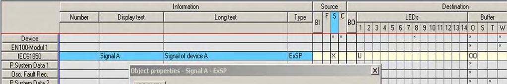
17 Allocation of an indication to check the IEC communication DEVICE A Open the parameter set off-line. Create - 2 pieces of internal single-point indication intsp for the function key and - 1 piece of single-point indication SP for the transmission via the IEC61850 station Allocate the 2 pieces of internal single-point indication to the source function key F1,F2 and destination CFC - the piece of single-point indication to the source CFC and destination LED1 and system interface S

18 Allocation of an indication to check the IEC communication DEVICE A The new signal from the source CFC is now allocated to LED and interface S

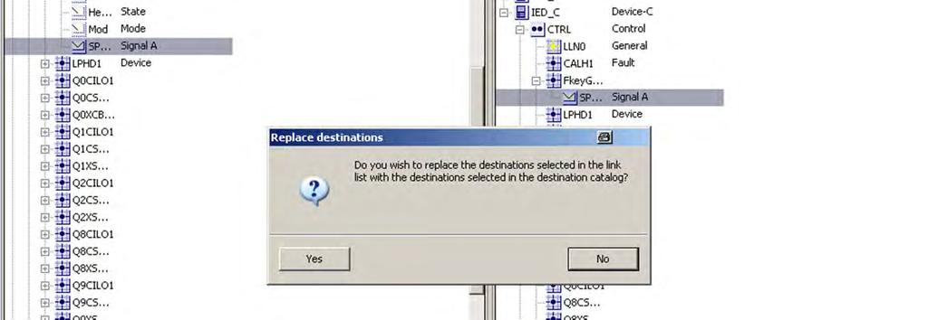
.")
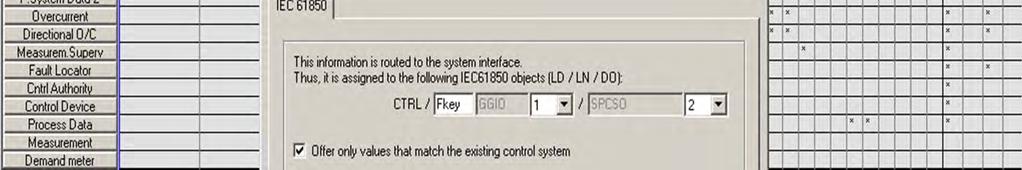
19 Allocation of an indication to check the IEC communication DEVICE A After the selection of destination S, a setting window appears for the allocation of the IEC61850 object: A name has to be assigned for the LN (logical node). The information then appears in the IEC61850 station under this structure.

20 Allocation of an indication to check the IEC communication DEVICE A The function keys are interconnected in the CFC with the help of an RS flipflop module so that the ON and OFF state can be presented permanently.
21 Work in accordance with the CFC standard recipe! 1. Allocate to CFC 2. Save the allocation matrix 3. Insert a CFC plan 4. Draw the plan 5. Check and optimize the running sequence 6. Compile the plan 7. Save the parameter set

22 Allocation of an indication to check the IEC communication DEVICE A Insert a new CFC-Chart communication check

23 Allocation of an indication to check the IEC communication DEVICE A After compilation you have to save the parameter set by clicking onto the disk symbol.
, an information is created in the")
24 DEVICE B In the device B, the SIGNAL information from device A is received from source S. With the help of the type external single-point indication from the information catalog (type:exsp), an information is created in the matrix and allocated to source S and destination LED1.
25 DEVICE B

26 DEVICE B The name of the LN does not have to be identical with the name of the LN of device 1. Nevertheless, for reasons of clarity, it is advisable to assign the same names to be able to find the corresponding information in the IEC61850 station easier.

27 Among the object properties of the parameter set, the following entries can be found: IP-address Subnet mask Standard gateway IED name


28 These settings are relevant if DIGSI communicates with the protection device directly via Ethernet. The IEC61850 station is then unnecessary. For this example, the communication parameters are entered in the IEC61850 station and accepted.

29 Creating an IEC61850 station New in DIGSI 4 is the IEC station, which is added to the project via the context menu, for example. Such a station combines several devices communicating with each other via Ethernet in accordance with IEC61850.

30 Creating an IEC61850 station Object properties of the IEC61850 station: Selection of the users Important: Only potential users whose parameter sets have been opened at least once before are offered here.


31 The IEC61850 station can now be opened.


32 The network area shows the current network structure. Subnets... users... IP addresses - all basic information at a glance! If you are interested in details, the properties window helps. It immediately provides the appropriate information independent of the selected element.

33 Define the Start-IP address first.
34 .and second actualize the others automatically

35 pay attention: Overwriting all IPaddresses automatically possible


36 In the interconnections area, you determine the scope of the data exchange between the users of an IEC61850 station. For that, you interconnect data objects of two (or more) users.

37 Interconnection of sources and destinations from catalogues For that, select a data object of user A as the source and interconnect it with a data object of user B as the destination. The source and destination objects are clearly arranged in separate windows in the form of hierarchical tree structures (catalogues).

38 Select the source information first by double clicking the desired information


39 Afterwards the source information will be displayed.


40 Second you have to select the destination information by double clicking within the destination window

41 The destination information is now displayed.

42 Just repeat it for additional devices, if available/necessary

43 Just repeat it for additional devices, if available/necessary

44 Interconnection of sources and destinations from catalogues Interconnections are always combined in applications. This is ideal to keep the overview even in the case of a huge amount of inter-connected information.

45 Standard and SIPROTEC text We pick up the user in his/her usual world: Apart from the standard text, he/she also sees the text of the assigned SIPROTEC object or at least a text in accordance with the SIPROTEC language world.


46 At the end of work: Exporting in SCL With just a few mouse clicks you save the data in files, absolutely standard-compliant in SCL. They can thus be directly processed by an automation system such as, for example, SICAM PAS, or evaluated by configuration tools of other manufacturers.
47 Usability in the system configurator You can adapt the layout of the DIGSI system configurator user interface exactly to your needs: You can determine the size and position of the individual windows yourself, or you can combine different windows to a single one. If required, you can change from the static view to the dynamic one: Partial windows such as the properties are only displayed when the cursor is moved across. Of course, your personal user interface layout is saved while exiting the system configurator. Opened catalogue paths are memorized. You can undo every action, also several actions consecutively. beginning with DIGSI 4.81 a detailed representation view for IEC61850 parameters is possible

48 Saving is carried out automatically when exiting the system configurator.


49 Saving is carried out automatically when exiting the system configurator.

50 Updating an IEC61850 station within the object properties of the IEC61850 station

51 Updating an IEC61850 station Report


52 Updating an IEC61850 station


53 At the end, the individual parameter sets have to be transmitted to the protection devices

54 Checking the communication Switch Device A Device B F keys


55 Exporting an IEC61850 station

56 Exporting an IEC61850 station, Report

57 Indication of the quality of the LAN connection Extended the example: Check the LAN-connection by using the qualityinformation of the received GOOSE message in device B

58 Indication of the quality of the LAN connection Interrogation of the message status in CFC The status of the IEC61850 annunciation obtained from the system interface is checked in CFC. For this purpose the logic module SI_GET_STATUS is provided. The module SI_GET_STATUS decodes the status of a single point indication, whereby the structure of the single point indication routed to input X is decoded to the VALUE of the signal and the following status information:
59 The output NV generates a signal NV=1, when the annunciation is no longer updated (update at second intervals). The signal from the NV output can then be routed to a LED or output contact. The module SI_GET_STATUS can be applied in all process layers. At this point it is worth mentioning that the status of double point indications can also be interrogated in CFC. For this purpose CFC provides the module DI_GET_STATUS. Result: As long as the communication is functioning between the devices, the present state of the bus release annunciation can be obtained without ambiguity. A communication failure results in the appearance of the status NV message via CFC.
60 Thank you very much for your attention.
SIPROTEC 5 Application Note
 www.siemens.com/protection SIPROTEC 5 Application Note SIP5-APN-014: Answers for infrastructure and cities. SIPROTEC 5 - Application: SIP5-APN-014 Mixed configurations of SIPROTEC 4 and SIPROTEC 5 Content
SIPROTEC 5 Application Note
 www.siemens.com/protection SIPROTEC 5 Application Note SIP5-APN-007: with IEC 61850 Answers for infrastructure and cities. SIPROTEC 5 - Application: SIP5-APN-007 Interconnection of SIPROTEC 5 devices to
Remote Control SIPROTEC 4 via Ethernet-Modems 7XV585x and 7XV5655
 Remote Control SIPROTEC 4 via Ethernet-Modems 7XV585x and 7XV5655 General In principle the scope of functions of Ethernet-Modems correspond to the already known analog or digital telephone modems. Instead
SIPROTEC 3/4 central operation via Ethernet Serial-Hub
 L2 402,1A L3 402,1A L2 402,1A L3 402,1A Power Transmission and Distribution SIPROTEC 3/4 central operation via Ethernet Serial-Hub General The serial hub and the associated configuration software may be
Experience with IEC based Systems
 Klaus-Peter Brand April 2006 Experience with IEC 61850 based Systems ABB - 1 - IEC61850 Experience Content IEC 61850 Experience with Systems ABB University Switzerland - 2 - First experiences Experience
SIPROTEC 5 Application Note
 s www.siemens.com/protection SIPROTEC 5 Application Note SIP5-APN-013: devices Answers for infrastructure and cities. SIPROTEC 5 - Application: devices Content 1 Application: devices 3 1.1 Summary 3 1.2
Workflow description for Feeder Automation with FASE
 FASE_Workflow_Descriprion_130130.docx Page: 1 / 51 Workflow description for Feeder Automation with FASE Author Name Department Version Date Markus Spangler / Leonid Borisuk IC SG EA PRO LM2 / SYS OP TRC
SIPROTEC 5 Application Note
 www.siemens.com/protection SIPROTEC 5 Application Note SIP5-APN-012 : Control of Breaker-and-a-half diameters and double busbar configurations and use of Phasor Measurement Unit (PMU) Answers for infrastructure
The System for Power Automation
 Basics 1 Tasks and solution The System for Automation The Tasks: Scalable system for Distributed process connection Process visualization Interface to control centre The Solution: Automation System PTD-SE-A2/
Remote control SIPROTEC 4 with EN100 over ISDN-Modem-Router
 Reset MoRoS Power COM Data Status Anr. L1 Anr. L2 Anr. L3 Anr. Erde Automat RUN ERROR Anr. L1 Anr. L2 Anr. L3 Anr. Erde Automat RUN ERROR Anr. L1 Anr. L2 Anr. L3 Anr. Erde Automat RUN ERROR Anr. L1 Anr.
SIPROTEC 5 Application. SIP5-APN-027: Change of switching authority via function keys.
 www.siemens.com/protection SIP5-APN-027: Answers for infrastructure and cities. SIPROTEC 5 - Application: Change of switching authority via function keys Content: 1 3 1.1 Introduction 3 1.2 Configuration
SIPROTEC 5 Application Note
 www.siemens.com/protection SIPROTEC 5 Application Note SIP5-APN-011: Answers for infrastructure and cities. SIPROTEC 5 - Application: SIP5-APN-001 Content 1 Application: 3 1.1 Summary 3 1.2 Application
SIPROTEC 5 Application Note
 www.siemens.com/protection SIPROTEC 5 Application Note SIP5-APN-010: Answers for infrastructure and cities. SIPROTEC 5 - Application: SIP5-APN-010 SIPROTEC 5 Application Content 1 Application 3 1.1 Summary
SIPROTEC 5 Application Note
 www.siemens.com/protection SIPROTEC 5 Application Note SIP5-APN-020: Answers for infrastructure and cities. SIPROTEC 5 - Application: Content 1 Application: 3 1.1 Summary 3 1.2 General 3 1.3 Download PICS
SICAM ertu Your Entry to Telecontrol Technology with Extended Functionality
 SICAM ertu Your Entry to Telecontrol Technology with Extended Functionality Power Transmission and Distribution The Comprehensive Solution SICAM ertu offers all you need for telecontrol, and plenty more
Substation to substation (ss2ss) GOOSE exchange for critical relay operations
 GOOSE exchange for critical relay operations") CIGRÉ Canada 21, rue d Artois, F-75008 PARIS (CIGRE-130) Conference on Power Systems http : //www.cigre.org Vancouver, October 17-19, 2010 Substation to substation (ss2ss) GOOSE exchange for critical relay
CIGRÉ Canada 21, rue d Artois, F-75008 PARIS (CIGRE-130) Conference on Power Systems http : //www.cigre.org Vancouver, October 17-19, 2010 Substation to substation (ss2ss) GOOSE exchange for critical relay
AirLive RS Security Bandwidth Management. Quick Setup Guide
 AirLive RS-2000 Security Bandwidth Management Quick Setup Guide Important Information The AP mode s default IP address is The default Subnet Mask is The default login name is The default password is!!!!
SIPROTEC 4 SIPROTEC Compact Reyrolle IEDs. Ethernet Module EN100 for IEC with electrical/optical 100 MBit Interface. Preface.
 Preface SIPROTEC 4 SIPROTEC Compact Reyrolle IEDs Ethernet Module EN100 for IEC 61850 with electrical/optical 100 MBit Interface Manual Contents Introduction 1 Design of the Ethernet Modules 2 Commissioning
SIPROTEC 5 Application Note
 www.siemens.com/protection SIPROTEC 5 Application Note SIP5-APN-001: Properties and Functional Structure Answers for infrastructure and cities SIPROTEC 5 Properties SIPROTEC 5 - Application: SIP5-APN-001
SIPROTEC 5 Engineering Guide DIGSI 5
 Preface Open Source Software SIPROTEC 5 Engineering Guide DIGSI 5 V6.0 and higher Table of Contents DIGSI 5 Overview 1 Essential Steps during Engineering 2 Loading Configuration into SIPROTEC 5 Device
Power Products. Protection and Control IED Manager PCM600 Product Guide
 Power Products Protection and Control IED Manager Product Guide Contents 1. Description............................ 3 2. Tool variants........................... 3 3. Connectivity packages...................
SIPROTEC 5 Application Note
 www.siemens.com/protection SIPROTEC 5 Application Note SIP5-APN-019: Flexible Engineering Modeling the System with the Options of IEC 61850 Answers for infrastructure and cities. SIPROTEC 5 - Application:
CFC. Special functions from SIMATIC S7 CFC V7.0 SP1 onwards
 CFC Function Function expansions from SIMATIC S7 CFC V7.1 onwards Forcing of values of an interconnected input: by means of the "Force functionality", interconnected block inputs can be forced to use the
SIPROTEC 5 V7.8 Protection, automation and monitoring for digital substations
 SIPROTEC 5 V7.8 Protection, automation and monitoring for digital substations siemens.com/siprotec5 SIPROTEC 5 Table of content Introduction New functions of V7.8 SIPROTEC 5 - the core of Digital Substation
A Collation & Analysis Methodology for Substation Event Data via a Web Interface (supporting COMTRADE, GOOSE & MMS Data Sources from Multiple Vendors)
") 1 A Collation & Analysis Methodology for Substation Event Data via a Web Interface (supporting COMTRADE, GOOSE & MMS Data Sources from Multiple Vendors) Abstract Author: Bruce Mackay Email Address: bruce.mackay@concogrp.com
1 A Collation & Analysis Methodology for Substation Event Data via a Web Interface (supporting COMTRADE, GOOSE & MMS Data Sources from Multiple Vendors) Abstract Author: Bruce Mackay Email Address: bruce.mackay@concogrp.com
Application program usage. Functional description. instabus EIB Application Program Description. December IP-Router
 Application program usage Product family: Product type: Manufacturer: Name: Order-No.: System devices IP- Siemens Functional description IP N146 5WG1 146-1AB01 The IP N146 is a DIN rail mounted device.
Information About the Getting Started PCS 7 - First Steps Documentation
 Preface Information About the Getting Started with PCS 7; The First Steps documentation uses a simple sample project to show you the fundamental procedures and the interaction of the software components
Protective Relays & SCADA Systems
 14 SWITCHGEAR Protective Relays & SCADA Systems SCADA Substation Automation SICAM PAS & PQ Analyzer SICAM PAS (Power Automation System) is a complete substation automation control and protection system
Smart Serial. Show interfaces. Shut down. logging synchronous
 SEMESTER 2 Chapter 2 Static Networking V 4.0 2.1.1 What are the primary responsibilities of the router? 2.1.3 What is the first serial connector described called at the router end? What is the first serial
Process Control System PCS 7 V7.0. Getting Started First Steps Documentation November 2006
 Process Control System PCS 7 V7.0 Getting Started First Steps Documentation November 2006 Qualified Personnel Only qualified personnel should be allowed to install and work on this equipment. Qualified
UPGRADE AND APPLICATION OF AUTOMATION SYSTEM IN T.S. 110/35/10 KV PETROVEC
 ofpowersystems 2014 UPGRADE AND APPLICATION OF AUTOMATION SYSTEM IN T.S. 110/35/10 KV PETROVEC Vasilija Sarac 1, Dragan Minovski 2, Goran Cogelja Faculty of Electrical Engineering, University Goce Delcev,
The OSI Model. Open Systems Interconnection (OSI). Developed by the International Organization for Standardization (ISO).
. Developed by the International Organization for Standardization (ISO).") Network Models The OSI Model Open Systems Interconnection (OSI). Developed by the International Organization for Standardization (ISO). Model for understanding and developing computer-to-computer communication
Network Models The OSI Model Open Systems Interconnection (OSI). Developed by the International Organization for Standardization (ISO). Model for understanding and developing computer-to-computer communication
SIPROTEC 4. Ethernet Module EN100 for IEC with electrical/optical 100 MBit Interface. Preface. Contents. Introduction 1
 Preface SIPROTEC 4 Ethernet Module E100 for IEC 61850 with electrical/optical 100 MBit Interface Manual Contents Introduction 1 Design of the Ethernet Modules 2 Commissioning in the Device 3 Integration
H3C S12500 VLAN Configuration examples
 H3C S12500 VLAN Configuration examples Copyright 2014 Hangzhou H3C Technologies Co., Ltd. All rights reserved. No part of this manual may be reproduced or transmitted in any form or by any means without
Lab 1.3.2: Review of Concepts from Exploration 1 - Challenge
 Lab 1.3.2: Review of Concepts from Exploration 1 - Challenge Topology Diagram Learning Objectives Upon completion of this lab, you will be able to: Create a logical topology given network requirements
Substation Automation based on IEC Claes Rytoft ABB Power Systems
 Substation Automation based on IEC 61850 Claes Rytoft ABB Power Systems BayNetworks Development of SA SA conventional MMI / Control Board NCC SA with interbay bus NCC SA with interbay & process bus NCC
Quick Start Guideline MICRO PANEL
 Quick Start Guideline MICRO PANEL XV-102 3.5" Document M003087-01 Edition 07/2009 Imprint MICRO PANEL XV-102 3.5" Manufacturer Product Company Micro Innovation AG Spinnereistrasse 8-14 CH-9008 St. Gallen
Products for digital substations SIPROTEC 6MU805. Merging Unit for conventional instrument transformer. Integrated PRP, HSR. siemens.
 Products for digital substations SIPROTEC 6MU805 Merging Unit for conventional instrument transformer Integrated PRP, HSR siemens.com/processbus built to create digital substations based on IEC 61850-9-2
8.9.2 Lab: Configure an Ethernet NIC to use DHCP in Windows Vista
 8.9.2 Lab: Configure an Ethernet NIC to use DHCP in Windows Vista Introduction If Vista is not available in your classroom, you may complete this lab by viewing the figures in this document. Print and
For your own safety, please observe the warnings and safety instructions contained in this document.
 Preface DIGSI CFC V4.87 Manual Contents Product Overview 1 Getting Started 2 Implementation Examples 3 CFC Blocks 4 Literature Glossary Index E50417-H1176-C098-B2 NOTE For your own safety, please observe
Digital Grid Products At a Glance Protection, Substation Automation, Power Quality
 Digital Grid Products At a Glance Protection, Substation Automation, Power Quality siemens.com/digitalgrid Digital Grid Products Broadest portfolio strong brands Substation Automation, RTU s Power Quality
MiPDF.COM. 1. Convert the decimal number 231 into its binary equivalent. Select the correct answer from the list below.
 CCNA1 v6.0 Pretest Exam Answers 2017 (100%) MiPDF.COM 1. Convert the decimal number 231 into its binary equivalent. Select the correct answer from the list below. 11110010 11011011 11110110 11100111* 11100101
Router Router Microprocessor controlled traffic direction home router DSL modem Computer Enterprise routers Core routers
 Router Router is a Microprocessor controlled device that forwards data packets across the computer network. It is used to connect two or more data lines from different net works. The function of the router
IEC meets Industrial IT
 IEC 61850 meets Industrial IT Lars Andersson, Klaus-Peter Brand, Petra Reinhardt The international electrical engineering community is continuously creating new global standards. These are not only important
TIA Portal Workshop. Unrestricted. Siemens AG All rights reserved.
 TIA Portal Workshop Unrestricted Siemens AG 2015. All rights reserved. SIMATIC S7-1500: Modular Controller for the Mid to Upper Performance Range Page 11 Siemens AG 2015 SIMATIC S7-1500: Modules Single-tier
Ahead of the challenge, ahead of the change. Beyond classical substation How seamless communication networks can be used in special applications
 Ahead of the challenge, ahead of the change Beyond classical substation How seamless communication networks can be used in special applications siemens.com/energy-management Agenda Today s reliability
Send documentation feedback to Supported Functionalities - Switches and IEDs
 CHAPTER 4 The CGDS Designer allows you create a substation topology. The Cisco Connected Grid Design Suite (CGDS) application allows you to design the integrated substation LAN by analyzing configurations
Help Volume Agilent Technologies. All rights reserved. Agilent E2485A Memory Expansion Interface
 Help Volume 1994-2002 Agilent Technologies. All rights reserved. Agilent E2485A Memory Expansion Interface Agilent E2485A Memory Expansion Interface The E2485A Memory Expansion Interface lets you use the
Introduction to TCP/IP
 Introduction to TCP/IP Properties and characteristics of TCP/IP IPv4 IPv6 Public vs private vs APIPA/link local Static vs dynamic Client-side DNS settings Client-side DHCP Subnet mask vs CIDR Gateway TCP/IP
EXAM - HP0-Y52. Applying HP FlexNetwork Fundamentals. Buy Full Product.
 HP EXAM - HP0-Y52 Applying HP FlexNetwork Fundamentals Buy Full Product http://www.examskey.com/hp0-y52.html Examskey HP HP0-Y52 exam demo product is here for you to test the quality of the product. This
Any offsets needing less or more than 1 hr will need special programming (call our tech support). Entering Mode Programming. Exiting Programming
. Entering Mode Programming. Exiting Programming") Adjusting Time Zone Clocks The basic mode for adjusting a time zone clock are primarily: The basic mode for adjusting a time zone clock are primarily: 21, 24 and 51-1 (51-1 is for Alpha Characters) Mode
Adjusting Time Zone Clocks The basic mode for adjusting a time zone clock are primarily: The basic mode for adjusting a time zone clock are primarily: 21, 24 and 51-1 (51-1 is for Alpha Characters) Mode
Help Volume Hewlett Packard Company. All rights reserved. Toolsets: IA Format Utility
 Help Volume 1997-2002 Hewlett Packard Company. All rights reserved. Toolsets: IA Format Utility Using the IA Format Utility The IA Format Utility tool lets you convert a.r (dot R) file into an inverse
Easily configurable HMI system for power automation siemens.com/sicam
 SICAM SCC Easily configurable HMI system for power automation siemens.com/sicam Small components big prospects: Your SICAM SCC station control Power grid operation is becoming more and more dynamic. To
6 Chapter 6. Figure 1 Required Unique Addresses
 6 Chapter 6 6.1 Public and Private IP Addresses The stability of the Internet depends directly on the uniqueness of publicly used network addresses. In Figure 1 Required Unique Addresses, there is an issue
IP Addressing and Subnetting
 IP Addressing and Subnetting Internet Layer The purpose of the Internet layer is to send packets from a network node and have them arrive at the destination node independent of the path taken. Internet
Station Automation based on IEC 61850
 IDS SAS Station Automation based on IEC 61850 IDS SAS Station automation based on IEC 61850 The IDS SAS station automation system was developed on the basis of the IEC 61850 standard. With this system,
Festo Field Device Tool FFT. Description. Online help FFT f [ ]
![Festo Field Device Tool FFT. Description. Online help FFT f [ ]](/thumbs/92/107768691.jpg "Festo Field Device Tool FFT. Description. Online help FFT f [ ]") FFT Description Online help FFT 8075018 2017-05f [8075020] Table of Contents 1 Information on the Festo Field Device Tool... 1 1.1 Overview... 1 1.2 Scan protocols... 2 1.2.1 Multicast... 2 1.2.2 Broadcast...
FFT Description Online help FFT 8075018 2017-05f [8075020] Table of Contents 1 Information on the Festo Field Device Tool... 1 1.1 Overview... 1 1.2 Scan protocols... 2 1.2.1 Multicast... 2 1.2.2 Broadcast...
SIPROTEC 7SC805. Merging Unit for conventional instrument transformer. Products for digital substations.
 Products for digital substations SIPROTEC 7SC805 Merging Unit for conventional instrument transformer Integrated PRP, HSR www.siemens.com/processbus built to create digital substations based on IEC 61850-9-2
Lab 2.8.2: Challenge Static Route Configuration
 Topology Diagram Addressing Table Device Interface IP Address Subnet Mask Default Gateway BRANCH HQ ISP PC1 PC2 Web Server Fa0/0 S0/0/0 Fa0/0 S0/0/0 S0/0/1 209.165.201.2 255.255.255.252 Fa0/0 209.165.200.225
Network Devices,Frame Relay and X.25
 Network Devices,Frame Relay and X.25 Hardware/Networking Devices: Networking hardware may also be known as network equipment computer networking devices. Network Interface Card (NIC): NIC provides a physical
Operation manual. DeviceControl NomadLink Network Control and Monitoring Software. Rev Item no. OM-DC
 Operation manual DeviceControl NomadLink Network Control and Monitoring Software Rev. 2.0.0 Item no. OM-DC 1 contents 1 CONTENTS...2 2 DeviceControl InTroduCtion...4 2.1 Overview...4 2.2 New features in
Chapter 9: Subnetting IP Networks
 Chapter 9: Subnetting IP Networks Network Segmentation Reasons for Subnetting Subnetting is the process of segmenting a network into multiple smaller network spaces called subnetworks or subnets. The purpose
Application program usage. Functional description. instabus EIB Application Program Description. March IP-Router
 IP- 001002 Application program usage Product family: Product type: Manufacturer: Name: Order-No.: System devices IP- Siemens Functional description IP N146 5WG1 146-1AB01 The IP N146 is a DIN rail mounted
SIPROTEC Overcurrent Protection 7SJ80. Motor Protection 7SK80. Preface. Content. Data in the PROFINET IO Mapping 1. Standard Mapping
 Preface SIPROTEC Overcurrent Protection 7SJ80 Motor Protection 7SK80 Content Data in the PROFINET IO Mapping 1 Standard Mapping 3-1 2 Glossary Index Communication Module PROFINET IO Bus Mapping C53000-L1840-C362-1
2 Preparation. 2.1 Items to Check Connecting PC with GP Setting PC Network Setting GP Network
 2 Preparation 2.1 Items to Check...2-2 2.2 Connecting PC with GP...2-6 2.3 Setting PC Network...2-9 2.4 Setting GP Network...2-21 Pro-Server EX Reference Manual 2-1 Items to Check 2.1 Items to Check Before
Before installing this product, ensure that the following prerequisites are completed.
 2 Preparation 2.1 Items to Check...2-2 2.2 Connecting PC with display unit...2-6 2.3 Setting PC Network...2-7 2.4 Set the network of display unit...2-19 2-1 Items to Check 2.1 Items to Check Before installing
SIMATIC NET. Industrial Ethernet Security SCALANCE S615 Getting Started. Preface. Connecting SCALANCE S615 to the WAN 1
 Preface Connecting SCALANCE S615 to the WAN 1 SIMATIC NET VPN tunnel between SCALANCE S615 and 2 SINEMA RC Server Industrial Ethernet Security Getting Started 07/2017 C79000-G8976-C390-02 Legal information
Innovative Electronics for a Changing World INDEX
 Innovative Electronics for a Changing World INDEX 1. SYSTEM DESCRIPTION 2. BOARD CONNECTIONS terminals and indicators 3. CONNECTION DIAGRAM 4. START UP GUIDE and passwords 5. HOME PAGE 6. STATUS PAGE 7.
Lab Correcting RIPv2 Routing Problems
 Lab 9.4.2 Correcting RIPv2 Routing Problems e Interface IP Address Subnet Mask Default Gateway Device Host Name Interface IP Address Subnet Mask Default Gateway R1 BRANCH1 Fast Ethernet 0/0 172.16.0.1
Quick Start Guide NETL ink Ethernet Gateways
 Version en as of FW. Quick Start Guide NETL ink Ethernet Gateways www.helmholz.com Content. Introduction. Checking the Network Situation. Preparing the NETL ink. IP Address Settings on the PG/PC Network
IPAliasRedundancy. IEC Library for ACSELERATOR RTAC Projects. SEL Automation Controllers
 IPAliasRedundancy IEC 61131 Library for ACSELERATOR RTAC Projects SEL Automation Controllers Table of Contents Section 1: IPAliasRedundancy Introduction... 3 Supported Firmware Versions... 6 Function Blocks...
Use of the application program. 1. Functional description. instabus EIB Application Program Description. August 2016.
 IP- 001031 Table of contents Use of the application program 1 1. Functional description 1 2. Communication objects 4 3. s 4 General 4 Routing (Bus > IP) 4 Routing (IP > Bus) 5 IP 5 Setting the additional
Lab 7.1.9b Introduction to Fluke Protocol Inspector
 Lab 7.1.9b Introduction to Fluke Protocol Inspector Objective This lab is a tutorial demonstrating how to use the Fluke Networks Protocol Inspector to analyze network traffic and data frames. This lab
Liquid4CONTROL. User Guide FA
 Liquid4CONTROL User Guide FA0000-01 Contents Introduction3 System Requirements3 Installation3 Network Connections - setting up your computer and Liquid4Pre on the network4 Opening the Software 11 Multiple
Application Note Configuring the Ascend MAX800 for use with Clipmail in a private network
 Application Note Configuring the Ascend MAX800 for use with Clipmail in a private network Introduction This Application Note guides the ClipMail user through the MAX800 router configuration process by
Product Families and Positioning. Protection Portfolio
 Product Families and Positioning Protection Portfolio siemens.com/energy-automation-products Agenda Protection Portfolio SIPROTEC 5 SIPROTEC Compact SIPROTEC 4 Reyrolle Page 2 Protection portfolio Fields
R&S LXI Class C Support V1.21 (XP)
") Test and Measurement Division Release Notes for R&S LXI Class C Support V1.21 (XP) R&S FSP Spectrum Analyzers R&S FSU Spectrum Analyzers R&S FSG Signal Analyzers R&S FSQ Signal Analyzers Printed in the
Test and Measurement Division Release Notes for R&S LXI Class C Support V1.21 (XP) R&S FSP Spectrum Analyzers R&S FSU Spectrum Analyzers R&S FSG Signal Analyzers R&S FSQ Signal Analyzers Printed in the
A Division of Cisco Systems, Inc. Dual-Band. Wireless A/G g a. User Guide. Game Adapter WIRELESS WGA54AG (EU/LA/UK) Model No.
 Model No.") A Division of Cisco Systems, Inc. Dual-Band 5GHz 2, 4GHz 802.11a 802.11g WIRELESS Wireless A/G Game Adapter User Guide Model No. WGA54AG (EU/LA/UK) Copyright and Trademarks Specifications are subject to
A Division of Cisco Systems, Inc. Dual-Band 5GHz 2, 4GHz 802.11a 802.11g WIRELESS Wireless A/G Game Adapter User Guide Model No. WGA54AG (EU/LA/UK) Copyright and Trademarks Specifications are subject to
Energy Automation Catalog SICAM
 SICAM PAS Software 6MD9 Energy Automation Catalog SICAM 4.1.2 2007 Power Transmission and Distribution SICAM PAS Software 6MD9 Catalog SICAM 4.1.2 2007 Supersedes: Katalog SICAM 4.1.2 2006 Contents System
Perfect protection smallest space
 www.siemens.com/energy/protection Perfect protection smallest space The SIPROTEC Compact device range redefines protection technology Answers for energy. SIPROTEC Compact is the ideal solution for almost
DASHBOARD PERFORMANCE INDICATOR DATABASE SYSTEM (PIDS) USER MANUAL LIBERIA STRATEGIC ANALYSIS TABLE OF CONTETABLE OF CONT. Version 1.
 USER MANUAL LIBERIA STRATEGIC ANALYSIS TABLE OF CONTETABLE OF CONT. Version 1.") UNITED STATES AGENCY FOR INTERNATIONAL DEVELOPMENT TABLE OF CONTETABLE OF CONT PERFORMANCE INDICATOR DATABASE SYSTEM (PIDS) LIBERIA STRATEGIC ANALYSIS DASHBOARD USER MANUAL Version 1.0 PERFORMANCE INDICATOR
UNITED STATES AGENCY FOR INTERNATIONAL DEVELOPMENT TABLE OF CONTETABLE OF CONT PERFORMANCE INDICATOR DATABASE SYSTEM (PIDS) LIBERIA STRATEGIC ANALYSIS DASHBOARD USER MANUAL Version 1.0 PERFORMANCE INDICATOR
SIMATIC HMI. WinCC V7.0 SP1 MDM - WinCC/Options for Process Control. Overview of process control system options 1. OS Project Editor 2.
 Overview of process control system options 1 OS Project Editor 2 SIMATIC HMI WinCC V7.0 SP1 MDM - WinCC/Options for Process Control System Manual Horn 3 Time Synchronization 4 Lifebeat Monitoring 5 Picture
INSTRUCTION MANUAL. Web server description. AQ 300 Series
 INSTRUCTION MANUAL Web server description AQ 300 Series Instruction manual Web server description 2 (22) Revision 1.0 Date August 2013 Changes - N/A Instruction manual Web server description 3 (22) TABLE
KV-901T & AV-901R User s Guide
 KV-901T & AV-901R User s Guide Copyright 2011 Beacon Extender Inc. All rights reserved. Version 5.0 1. Introduction The KV-901T/AV-901R is a solution of Audio/Video extension over IP Ethernet LAN. The
Multitouch/BACnet Functional description UMG 604 / UMG 605 / UMG 508 / UMG 511
 Functional description Multitouch/BACnet UMG 604 / UMG 605 / UMG 508 / UMG 511 Doc no. 2.033.107.0 www.janitza.com BACnet activation UMG 604, Article no.: 52.16.081 BACnet activation UMG 605, Article no.:
SERVICE TOOL MAP110 USER MANUAL. Landis+Gyr. H c en
 SERVICE TOOL Landis+Gyr MAP110 USER MANUAL H 71 0200 0332 c en Revision History Index Date Comments a 28.02.2005 First edition b 31.05.2005 Changes to release 1.1 c 22.09.2005 Changes to release 1.2 subject
DOCUMENT COMPLIANCY MODULE
 DOCUMENT COMPLIANCY MODULE Author: R. Dighton Version 2.3 17/10/11 Copyright Micad Systems 2011 SECTION 1- INTRODUCTION 1.1. Compliancy Module 1.2. How to use Manual 1.3. Navigation 1.4. User Help Symbols
Revolutionary metering management in Romania
 Landis+Gyr@work Revolutionary metering management in Romania In 2002 Landis+Gyr was awarded a contract by the European Bank of Reconstruction and Development (EBRD). The EBRD was financing a metering system
Network II Lab 01. Part 01: Interface Overview. Program interface
 Part 01: Interface Overview Network II Lab 01 This initial interface contains ten components. If you are unsure of what a particular interface item does, move your mouse over the item and a help balloon
Blueprint Data Center
 Systems and Applications for Data Center Siemens Industy 1. Overview / Purpose In EM EA the datacenter market is seen as one of the fastest growing of the energy businesses. This blueprint is designed
A5500 Configuration Guide
 A5500 Configuration Guide Sri Ram Kishore February 2012 Table of contents Gateway Configuration... 3 Accessing your gateway configuration tool... 3 Configuring your broadband Internet access... 3 Configuring
Protection and Control IED Manager PCM600 Product Guide
 Product Guide Contents 1. Description...3 2. Project explorer...4 3. Parameter setting...4 4. Graphical application configuration...4 5. Signal matrix...5 6. Graphical display editor...5 7. Hardware configuration...6
Projector Operation Guide
 Projector Operation Guide Contents 2 Introduction Making effective use of your projector... 6 Sending Images Via a Network (EMP NS Connection) (EB-826W/825/85).......... 6 Monitor, configure, and control
Go beyond... IEC Leverage the full potential with leading-edge expertise. Answers for infrastructure and cities.
 Go beyond... IEC 61850 Leverage the full potential with leading-edge expertise www.siemens.com/iec61850 HSR, PRP integrated Certified according to IEC 61850 Edition 2 Answers for infrastructure and cities.
CCM 4300 Lecture 5 Computer Networks, Wireless and Mobile Communications. Dr Shahedur Rahman. Room: T115
 CCM 4300 Lecture 5 Computer Networks, Wireless and Mobile Communications Dr Shahedur Rahman s.rahman@mdx.ac.uk Room: T115 1 Recap of Last Session Described the physical layer Analogue and Digital signal
Networking Energisers to Perimeter Patrol through the Internet
 Networking Energisers to Perimeter Patrol through the Internet The installation of Energisers at different locations can be monitored using Perimeter Patrol at a central location. However, to achieve this
Table of Contents 1 GRE Configuration Point to Multi-Point GRE Tunnel Configuration 2-1
 Table of Contents 1 GRE Configuration 1-1 GRE Overview 1-1 Introduction to GRE 1-1 GRE Security Options 1-3 GRE Applications 1-3 Protocols and Standards 1-4 Configuring a GRE over IPv4 Tunnel 1-4 Configuration
Start-up Guide. Copyright 2015, Desoutter HP2 7SJ UK
 http://www.desouttertools.com Part no 6159922070 Issue no 01 Date 08-2015 Page 1/51 Start-up Guide Original instructions. Copyright 2015, Desoutter HP2 7SJ UK All rights reserved. Any unauthorized use
How to setup a basic proveos system
 How to setup a basic proveos system What you need: A proveos unit & included power supply, DVI-VGA adaptor, etc. A projector or LCD/Plasma display VGA or DVI cable of sufficient length Stereo (powered)
NETWORK LAB 2 Configuring Switch Desktop
 Configuring Switch 1. Select the switch tab and then add a switch from the list of switches we have to the workspace, we will choose (2950-24) switch. 2. Add a number of PCs next to the switch in order