Pan/Tilt Internet Camera
|
|
|
- Brittney Lee
- 5 years ago
- Views:
Transcription
1 Pan/Tilt Internet Camera User s Guide Rev. 2.1 (Aug., 2005) Made in Taiwan
2 1
3 TABLE OF CONTENTS ABOUT THIS GUIDE INTRODUCTION...5 FEATURES AND BENEFITS...6 UNPACKING THE PACKAGE...8 SYSTEM REQUIREMENT...9 PHYSICAL DESCRIPTION HARDWARE INSTALLATION...12 ATTACHING THE METAL CLIP...12 CONNECTING THE ETHERNET CABLE...13 ATTACHING THE POWER SUPPLY SECURITY APPLICATION OF THE CAMERA...15 APPLICATIONS...16 APPLICATION DIAGRAMS OF THE CAMERA
4 5. USING THE CAMERA...20 WEB CONFIGURATION UTILITY...20 SYSTEM ADMINISTRATION...22 VIEWING VIDEO IPVIEW PRO...47 INSTALLATION...47 GETTING STARTED...51 USING IPVIEW PRO...54 CONFIGURING THE SYSTEM APPENDIX...74 A. FREQUENTLY ASKED QUESTIONS...74 B. PING YOUR IP ADDRESS...76 C. TROUBLE SHOOTING...77 D. TIME ZONE TABLE...81 E. XPLUG CONTROL INSTALLATION...83 F. ADJUST INTERNET CAMERA FOCUS...87 G. SPECIFICATION...88 H. GLOSSARY OF TERMS
5 ABOUT THIS GUIDE This manual provides instructions and illustrations on how to use your Pan/Tilt Internet Camera, includes: Chapter 1, Introduction, provides the general information on the camera. Chapter 2, Hardware Installation, describes the hardware installation procedure for the camera. Chapter 3, Security, explains the security feature of the camera. Chapter 4, Application of the Camera, provides the illustrations of the camera s applications. Chapter 5, Using the Camera, guides you through the configuration using the web browser. Chapter 6, IPView Pro, helps you to install and use the software. Chapter 7, Appendix. Please note that the illustrations or setting values in this manual are FOR YOUR REFERENCE ONLY. The actual settings and values depend on your system and network. If you are not sure about the respective information, please ask your network administrator or MIS staff for help. 4
6 1 INTRODUCTION Thank you for purchasing the Pan/Tilt Internet Camera, a standalone system that can be connected directly to an Ethernet or Fast Ethernet. Compared to the conventional PC camera, the Pan/Tilt Internet Camera features a built-in CPU and web-based solutions that can provide a cost-effective solution to transmit the real-time high-quality video images for monitoring. The camera can be managed remotely, so that you can use a web browser to access and control it from any notebook/desktop PC over the Intranet or Internet. The simple installation procedures and webbased interface allow you to integrate it into your network easily. With comprehensive applications supported, the Internet camera is your best solution for remote monitor, high quality, and high performance video images. 5
7 Features and Benefits Simple To Use The Pan/Tilt Internet Camera is a standalone system with built-in CPU, no special hardware (such as a PC frame capture card) or software required. The camera supports DirectX 9.0; therefore, the only requirement you need is the web browser software such as Internet Explorer 5.0 or above. Once you have a valid IP Address, just connect it and you can view the picture from your camera. In addition, the camera s pan/tilt function allows you to adjust the camera for optimal viewing angle. You can tilt the camera right or left (up to 170/170 degrees), forward or backward (up to 45/90 degrees) using the Web Configuration Utility. Support Variety of Platforms The camera supports TCP/IP networking, SMTP , HTTP and other Internet related protocols. It can be utilized in a mixed operating system environment, including Windows 98SE/ME/ 2000/XP and Windows NT 4.0. It can be integrated easily into other www/intranet applications. Web Configuration Applying a standard web browser, the administrator can configure and manage the camera directly from its own web page via the Intranet or Internet. Up to 64 users name and password are permitted with privilege setting controlled by the administrator. 6
8 Remote Utility The powerful IPView Pro application assigns the administrator with a pre-defined user ID and password, allowing the administrator to modify the camera settings from the remote site via Intranet or Internet. When new firmware is available, you can also upgrade remotely over the network for added convenience. Users are also allowed to monitor the image, and take snapshots. Broad Range of Applications With today s high-speed Internet services, the camera can provide the ideal solution for live video images over the Intranet and Internet for remote monitoring. The camera allows remote access from a web browser for live image viewing, and allows the administrator to manage and control the camera anywhere and anytime in the world. Apply the camera to monitor various objects and places such as homes, offices, banks, hospitals, childcare centers, amusement parks and other varieties of industrial and public monitoring. The camera can also be used for intruder detection; in addition, it can capture still images for archiving and many more applications. 7
9 Unpacking the Package Unpack the package and check all the items carefully. In addition to this User s Guide, be certain that you have: One Pan/Tilt Internet Camera One AC power adapter suitable for your country s electric power One RJ-45 Ethernet Cable One Metal Clip One Quick Installation Guide One Installation CD-ROM If any item contained is damaged or missing, please contact your local dealer immediately. Also, keep the box and packing materials in case you need to ship the unit in the future. 8
10 System Requirement Networking Local Area Network: 10Base-T Ethernet or 100Base-TX Fast Ethernet Accessing the Camera For Web Browser Users Operating System: Microsoft Windows 98SE/ME/ 2000/XP CPU: Intel Pentium II, 266 MHz or above Memory Size: 32MB (64MB recommended) Resolution: 800x600 or above Microsoft Internet Explorer 5.0 or above For IPView Pro Application Users Operating System: Microsoft Windows 98SE/ME/ 2000/XP. CPU: Intel Pentium III, 450 MHz or above Memory Size: 128 MB (256 MB recommended) Resolution: 800x600 or above 9
11 Physical Description This section describes the externally components features of your camera. Front Panel There are two LED indicators on the front panel of the camera: Power LED and Link LED. 1. Power LED The Power LED is positioned on the right side of the two LEDs. A steady BLUE light confirms that the camera is powered on. 2. Link LED The Link LED is positioned on the left side of the two LEDs. A steady ORANGE light confirms that the camera has good connection to LAN connectivity. Dependent on the data traffic, the LED will begin to flash to indicate that the camera is receiving/sending data from/to the network. 10
12 Rear Panel 1 DC Power Connector 2 Reset Button 3 Network Cable Connector 1. DC Power Connector The DC power input connector is located on the camera s rear panel, and is labeled DC5V 2.5A with a single jack socket to supply power to the camera. Power will be generated when the power supply is connected to a wall outlet. 2. Reset Button Reset will be initiated when the reset button is pressed once, and Power LED begins to flash. Factory Reset will be initiated when the reset button is pressed continuously for three seconds or when Power LED begins to light up. Release the reset button and the Power LED will begin to flash, indicating the camera is changing to factory reset. The IP address will also return to the default setting as Network Cable Connector The camera s rear panel features an RJ-45 connector for connections to 10Base-T Ethernet cabling or 100Base-TX Fast Ethernet cabling (which should be Category 5 twisted-pair cable). The port supports the N-Way protocol and AutoMDIX function, allowing the camera to automatically detect or negotiate the transmission speed of the network. 11
.")
13 2 HARDWARE INSTALLATION Attaching the Metal Clip Ceiling screw Screw Screw Wall screw Wall screw Base of the camera Ceiling screw To attach the metal clip, remove the two rubber pads under the base of the camera firstly. Place the metal clip onto the camera base, and align the two holes of metal clip with two screw holes on the base. Secure the metal clip to the base with two screws (provided). Then, you can: 1. Install the camera to the ceiling using two ceiling screws ( ); or, 2. Install the camera to the wall using two wall screws ( ). 12
14 Connecting the Ethernet cable Connect an Ethernet cable to the network cable connector located on the camera s rear panel, and then attach it to the network. Attaching the Power Supply Attach the external power supply to the DC power input connector located on camera s rear panel, and then connect it to your local power supply. TIP: You can confirm power source is supplied from the Power LED on the camera is illuminated. 13
15 3 SECURITY To ensure the highest security and prevent unauthorized usage of the camera the Administrator has the exclusive privilege to access the System Administration for settings and control requirements to allow users the level of entry and authorize the privileges for all users. The camera supports multi-level password protection and access to the camera is strictly restricted to defined the user who has a User Name and User Password that is assigned by the Administrator. The administrator can release a public user name and password so when remote users access the camera they will have the right to view the image transmitted by the camera. NOTE: Since the default settings are Null String, it is highly recommended to set the "Admin ID" and "Admin Password" when you are the first time to use the camera. Once the ID and Password are defined, only the administrator has the access to management the camera. This procedure should be done as soon as possible since the security features with the camera will not be enabled until the "Admin ID" and "Admin Password" is defined. 14
16 4 APPLICATION OF THE CAMERA The camera can be applied in wide variety of applications. With the built-in CPU, it can work as a standalone system that provides a web-based solution transmitting high quality video images and sounds for monitoring purposes. It can be managed remotely, accessed and controlled from any PC desktop over the Intranet or Internet via a web browser. With the easy installation procedure, real-time live images will be available. In addition, once the camera is installed coupled with the IPView Pro application, you can further expand the scope of the camera. The following section will provide the typical applications for the camera along with the IPView Pro application, and also includes some basic knowledge to assist in the installation and configuration of the camera. 15
17 Applications Monitoring of local and remote places and objects such as construction sites, hospitals, amusement parks, schools and day-care centers through the use of a web browser. Capture single frame images from the IPView Pro application. Configure the camera to upload image or send-mail messages with a single frame image. 16

18 Application Diagrams of the Camera Home Applications 17
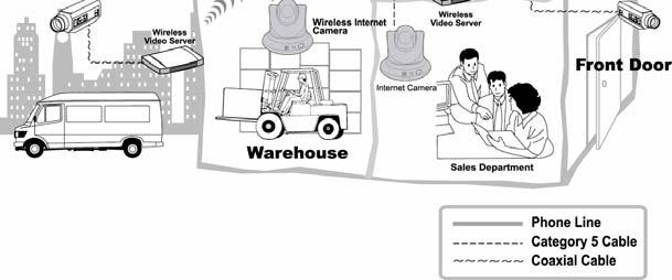
19 SOHO Applications 18


20 Enterprise Applications 19
21 5 USING THE CAMERA You can access and manage the camera through: 1) a web browser, and 2) the enclosed software IPView Pro. This chapter describes the Web Configuration Utility, and provides the instructions on using the camera with a web browser. Web Configuration Utility The camera must be configured through its built-in Web-based Configuration. (Extensive knowledge of LAN will be helpful in setting up the camera.) From the web browser, enter the default IP address to access the Welcome screen of the camera. To configure your camera, type in the address box. The number is the default IP address of your camera. Then, press [Enter]. NOTE: The computer s IP address must correspond with the camera s IP address in the same segment for the two devices to communicate. 20

22 Default IP address Pre-view area Welcome Screen of the Configuration Utility After the default IP address is entered from the browser, the camera Welcome screen will appear with a still image. There will be three options to choose from to set-up and view your camera, including: View Video ActiveX Mode View Video Java Mode System Administration 21

23 System Administration Under the Welcome screen of the Configuration Utility, click System Administration to enter the administration window that contains the settings required for the camera in the top menu bar, including Management, Configuration, Tools, Help, and Home. TIP: Once you have changed the settings in each option, click Save to store the settings, or Cancel to abandon, or Refresh to reload the status. During the configuration, whenever you click Home in the top menu bar will make you return to the Welcome window. System Administration Management The Management window contains the information of your configuration. Click the items in the left column to view your settings, including: System, Video, Network, and User. 22
24 System Click the System item in the left column to display the device status of your camera (as shown above). - Device Status: The information about the camera, including the Camera Name, Location, Model, Firmware Version, MAC Address and IP Address, can be found in this field. - Ethernet Status: You can monitor the networking status in this field, including the Link (network connection), Speed, and the Duplex mode. Video Click the Video item in the left column to display the video configuration of your camera. - Video Status: The video configuration about the camera, including the Video Resolution, Compression Rate, Frame Rate, Frame Size and IP Address, can be found in this field. 23

25 Network Click the Network item in the left column to display the information of the LAN. - Network Status: The items in this field display the information of the LAN, such as the IP Address, Subnet Mask, Default Gateway, Primary/Secondary DNS Address, Dynamic DNS, Secondary HTTP Port, UPnP, as well as the FTP/ upload status. 24
 information, including the user(s) IP")
26 User Click the User item in the left column to display the user(s) information. - Active Users: The items in this field display the user(s) information, including the user(s) IP address, Name, and DateTime. 25

27 System Administration Configuration The Configuration window contains commands for settings that are required to input key details to setup the camera for operation. Click Configuration in the top menu bar and the Configuration window will appear as below: System Click the System item in the left column to setup the basic configuration of your camera (as shown above). - System Setting: In this field, you can configure the basic information of your camera. Camera Name: This field is used to enter a descriptive name for the device. The default setting for the Camera Name is CS-xxxxxx, where xxxxxx is the last six digit of the MAC Address. The maximum length is 32 (printable ASCII). Location: This field is used to enter a descriptive name for the location used by the camera (optional). 26
28 Admin: This field is used to enter the administrator name along with the password to access the System Administration settings. Be sure to enter the password twice to confirm the details once in the Admin Password field and again in the Confirm Password field. The default setting for administrator is blank space (Null String), and you need to key in the administrator name with a maximum length of 12 (printable ASCII) characters and enter the administrator password with a maximum length of 8 (printable ASCII) characters. It is highly recommended to set the Admin ID and Admin Password as soon as possible to enable security option for the camera to function. LED Control: This option allows user to setup the LED illumination as desired. This feature provides the flexibility when surveillance activity is ON. There are three options as follows: Normal OFF Dummy Power - Steady On of the LED indicator. Link - Steady On of the LED indicator. When WLAN activity is present the LED indicator will flash steadily. Power - LED indicator is off. Link LED indicator is off. Power - Steady On of the LED indicator. Link - Steady On of the LED indicator with random flashing. The default setting for the LED control is at Normal. When you have configured the LED control, the correct illumination will be set after 1 minute. 27
 and 640x480.")
29 Video Click the Video item in the left column to setup the image configuration of your camera. - Video Setting: In this field, you can configure the basic information of your camera. Video Resolution: Select the desired video resolution format, including 160x120, 320x240 (default) and 640x480. Compression Rate: Select the desired compression rate with five levels from Very Low to Very High. Higher video compression rate will generate more compact file size with less video quality and vise-versa. The default setting is Medium. Frame Rate: Select the frame rate desired with default setting at Auto for optimal frame rate. Brightness Control: Adjust the brightness level with default setting at 64. Contrast Control: Adjust the contrast level with default setting at
30 Saturation Control: Adjust the saturation with default setting at 64. Light Frequency: Adjust the light frequency to suit your area of operation from the options either 50 Hz or 60 Hz (default). Mirror: You can select the Horizontal Mirror or Vertical Mirror option to display the image in a mirror mode. This function allow you to place the camera more flexibly (for example, you can attach the camera on the ceiling). Anti-Flicker: If you capture a flicker image because of the environment factor (for example, high light of lamp), please select this item to solve the problem. 29

31 Network Click the Network item in the left column to setup the LAN configuration of your camera. - TCP/IP: The items in this field display the information of the local area network. IP Address Mode: This field provides your with three options to select the IP Address Mode: Fixed IP Dynamic Address You can select this option and enter the IP address directly. The default settings are: IP Address Subnet Mask Default Gateway If your network uses the DHCP server, select this option. According to this setting, 30
32 (DHCP) PPPoE the camera will be assigned an IP address from the DHCP server automatically. Every time when the camera starts up, please make sure that the DHCP server is set to assign a static IP address to your camera. If your application requires a direct connection from an ADSL modem through the camera s RJ-45 LAN port, click this option and enter the User ID and Password into the respective boxes. (You should have an ISP PPPoE account.) The camera will get an IP address from the ISP as starting up. DNS IP Address: DNS (Domain Name System) server is an Internet service that translates domain names into IP addresses. Enter at least one DNS IP Address in this field. Dynamic DNS: The Dynamic DNS service allows you to alias a dynamic IP address to a static hostname in any of the domains, allowing your computer to be more easily accessed from various locations on the Internet. Second HTTP Port: The default port for communication is via port 80, and you can change it according to your network configuration. Select Enable from the option and enter the desired port number in the following box. UPnP: UPnP is the architecture for pervasive peerto-peer network connectivity of intelligent appliances, and PCs of all form factors. Check the Enable option to enable the function of your camera. 31

33 User Click the User item in the left column to add, edit and delete users for your camera. - User Access Control: Access Control: The administrator has the authority to give permission for the privilege to control the device to users by selecting Enable or Disable. The default setting is No. - Define Users: Use this field to add or delete users for your camera. Add User: Enter the user name in this box, and enter the user s password assigned by the administrator. The maximum password length is 8 (printable ASCII). The administrator has the authority to give permission for the privilege to control the Pan Tilt Control and Upload/ Video control to the users by selecting Yes or No to activate the Pan/Tilt control and Upload/ Video. To add a new user s name, enter the necessary information first and click the Add button. Delete User: Select the user you want to delete from the pull-down menu, and then click the Delete button. 32

34 User List: This list displays the current users status of your camera. DateTime Click the DateTime item in the left column to setup time and date for your camera, providing correct information for the remote users who might be thousands of miles away from the camera s location. - Date & Time: You can set up time and date manually or automatically by selecting the Synchronized with Time Server option. Synchronized with Time Server: Select this option and the time will be based on GMT setting. The time will be synchronized every 10 minutes. When selecting this option, you have to enter the required information in the following fields: IP Address Protocol Enter the IP Address of the Time Server in this box. Two options of NTP or Time are available for your selection to link with the Time 33

35 TimeZone Server. The default setting is NTP. Select the time zone for the region from the pull-down menu. Set Manually: Select this option to set the time manually. The system administrator must enter the date and time in the respective field manually. Upload Click the Upload item in the left column to setup configuration for FTP server, time schedule and manual operation. 34
36 - FTP Server: This field contains the following six basic settings for your FTP server. Host Address: The IP Address of the target FTP server. Port Number: The standard port number for the FTP server is Port 21, and it s also the default setting. If the FTP server uses a specific port, please confirm the IT manager. User Name: Enter the user name in this field. Password: Enter the user password in this field to login the FTP server. Directory Path: Enter an existing folder name in this field, and the images will be uploaded to the given folder. Passive Mode: This function depends on your FTP server. Please check with your IT manager if the FTP server uses passive mode. The default setting is No. - Time Schedule: Select the Enable upload video to FTP server option and enter the relevant information, such as the schedule, video frequency and base file name. Schedule: You can 1.) Choose Always to always upload the video to FTP server, or 2.) Set the Schedule to manage the uploading task. In the Schedule option, you can set the Day and Time Period option. Video Frequency: There are two ways to set the video frequency: 1.) Set Auto/1/2/3 frames per second, or 2.) Set the time in seconds for every frame. Base File Name: Enter the file name to make sure that the images could be saved as the base file name. 35

37 File: Since you may not upload only one image to the FTP server, you can choose the filing rule, including Overwrite, Date/Time Suffix, and set up the Sequence Number. - Manual Operation: When you click the Upload Video button in view video screen, it will start to upload the image. The setting refers to Base File Name and File information above. Click the item in the left column to setup configuration for account, time schedule and manual operation settings. - Account: This field contains the following six basic settings for your FTP server. 36
38 SMTP Server Address: SMTP (Simple Mail Transfer Protocol) is a protocol for sending messages between servers you need to input the mail server address in this field. Sender Address: Enter the address of the user who will send the . Receiver Address: Enter the address of the user who will receive the . User Name: Enter the user name in this field. Password: Enter the user password in this field to login receiver s mail server. - Time Schedule: Select the Enabl video to account option to set schedule to send . Please refer to the instruction in Upload section. The Interval option is to define time interval between two images sent. - Manual Operation: When you click the Video button in view video screen, it will start to image. The Interval option is to define time interval between two images sent. 37
39 System Administration Tools The Tools window contains commands for restarting the camera. Click Tools in the top menu bar and the Tools window will appear as below: FTP Server Test Click the FTP Server Test item in the left column to test your FTP server (as shown above). - Test FTP Server: Click the Test button to test the FTP server you provided. 38
40 Test Click the Test item in the left column to test your account. Reset - Test Account: Click the Test button to test the e- mail account you provided. Do you really want to reset this device? Click the Yes button from this option, and you can restart the camera just like turning the device off and on and saved settings are retained. If you do not want to reset the camera, exit this window without clicking Yes. Factory Reset Do you really want to factory reset this device? Click the Yes button from this option, and you can resume all factory default settings for the camera. If you do not want to restore the factory settings, exit this window without clicking Yes. Please NOTE that you have to configure the network settings again after a Factory Reset. 39

41 Firmware Upgrade When new firmware is available, you can upgrade it through this window. Click the Browse button to point to the firmware file, and then click Update to start upgrading. Backup Click the Backup item in the left column to backup the current configuration. 40
42 - Backup Device Configuration to File: Do you really want to backup the configuration to file? Click the Backup button from this option, and you can save the current configuration to file. - Restore Device Configuration from File: You can resume the device configuration from saved file in the computer. Click the Browse button to point to the file, and then click Restore to start restoring. 41

43 System Administration Help The Help window provides the basic information of the camera. Click Help in the top menu bar and the Help window will appear as below: About Displays the camera s model name and version. Once the configuration is completed, click Home to return to the Welcome screen and select the desired View Video option either through ActiveX Mode or Java Mode as described in the next section. Then, position the camera to the desired location appropriately for your purpose. Followed by adjustment of the camera focus, done manually by turning the lens clockwise or anti-clockwise to the desire image quality. Please refer to Appendix F for detailed instruction. 42

44 Viewing Video To view video images from the browser, click View Video ActiveX Mode or Java Mode from the Welcome screen to access the video images from your browser. Camera Name and Date/Time Camera Name and Date/Time View Image ActiveX Mode and Java Mode Camera Name & Date/time: The Camera name and the current date/time will be displayed when the related information are entered under Configuration of Web Configuration Utility. 43

45 Uploading/ ing Video In the View Video ActiveX Mode or Java Mode, you are allowed to use the Upload Video and Video options. Simply click the desired selection ON or OFF to utilize the options for each of the functions. Enable/Disable the Upload/ Function NOTE: 1. Please refer to the appendix on how to install ActiveX, including 1.) Install to the Web Server, and 2.) Install to your Local PC. 2. The administrator has the authority to set the upload/ video function through the setting in the Upload/ option under Configuration. 44

46 Controlling the Camera You can control the camera s viewing angel through the control buttons on the left side of the viewing window. Control buttons Adjusting the Viewing Angle To adjust the camera s viewing angel, simply click the Up/Down/ Left/Right button. Then, you can easily move the camera s lens to focus on the object that you want. Clicking the Home button allows you return to the original position. The Pan Degree and Tilt Degree options allow you to increase/ decrease the changing range (1~10) when you click the buttons. 45
47 Storing the Position You can store the position(s) that you want to monitor, so that you can quickly move the camera s lens to focus on the object that you want. You can store up to 24 positions in the camera (the number 0 is for default position Home ). To store the current position, select the setting number (1~24) from the pulldown list, and then click Set. You can enter the name for the position in the following box. To remove the stored position, select the position that you want to remove, and then click Clear. When you have stored the position in the camera, select the number (position) from the pull-down list, and then click Go To. The camera s lens will move to the position immediately. Swinging the Camera The camera can swing automatically between the stored positions. Once you have stored two (or more) positions in the camera, click Swing will have the camera swing from one position to another position. Click Stop to stop swinging. 46

48 6 IPVIEW PRO This chapter describes IPView Pro, which is a powerful software application designed with a user-friendly interface for ease of control and navigation requirements. Installation Step 1 Insert the CD-ROM into the CD-ROM drive to initiate the autorun program. The menu screen will appear as below: 47

49 Step 2 Click the IPView Pro item to activate the InstallShield Wizard. Click Next in the welcome screen. Step 3 Read and accept the License Agreement; then, click Yes. 48


50 Step 4 Choose the destination location. If no specific requirement, leave the default setting and click Next. Step 5 The InstallShield Wizard starts to install the software, and the progress bar indicates the installation is proceeding. 49

")

51 Step 6 If you use Windows 2000/XP, it will appear a Digital Signature warning screen. Click Continue Anyway (Windows XP) or Yes (Windows 2000). Windows XP Windows 2000 Step 7 Click Finish to complete the installation. 50

52 Getting Started This section describes the User Interface of IPView Pro, with detailed procedures for using the application. To start running IPView Pro, click Start > Programs > IPView Pro > IPView Pro. The main screen will appear as below: NOTE: IPView Pro requires the system s resolution setting up to 1024x768. Please configure the resolution to 1024x768 or higher; otherwise, it may shows incomplete screen when launching the program. 51
 on the right lower corner of the window to change the display mode: View Window View Mode Buttons Camera list mode Camera information mode Show the camera s")

53 Item Feature NO. Item Description Date/Time Show current date/time. Status Mode Window Show the camera s status in this window. Click the Change Status Mode button ( ) on the right lower corner of the window to change the display mode: View Window View Mode Buttons Camera list mode Camera information mode Show the camera s view in this window. Select the view mode from these buttons. Show one camera in View Window. Show four cameras in View Window. Show six cameras in View Window with the first one as the major view. Show eight cameras in View Window with the first one as the major view. Show nine cameras in View Window. Show ten cameras in View Window with the first two as the major views. Show thirteen cameras in View Window with the first one as the major view. Show sixteen cameras in View Window. 52
54 Key Lock Button Show the selected camera in full screen view. Enable displaying the video views in circles. Click to lock/unlock the camera. When locked, the user cannot operate any camera. Power Button Click to exit or minimize IPView Pro. Pan/Tilt Control Panel When the camera is added, the Pan/Tilt control buttons will appear on the panel, as shown below: / / / / / / / : Click these buttons to adjust the camera s viewing angle to Up/ Down/Left/Right/Left-Up/Left-Down/Right- Up/Right-Down. : Once you have saved two (or more) positions in the camera, click the Swing button to control the camera swinging from one position to another position. : Click the Home button to return the camera to the default position. Record Button Play Button System Configure Record video clip of the selected camera and save it in the computer. The storage position can be configured in System Configuration. When you click the button, you can select Manual Record, Schedule Record, or Motion Record. Play the recorded video file in the computer. Click to enter the System Configuration. 53
55 Using IPView Pro Adding a Camera To add a camera: 1. Click the System Configure button to enter the System Configuration. If you are not sure of the camera s IP address, you can click Search to search the available camera(s) within the network. 54

56 2. Select the camera you want by highlighting it, and then click Add Camera. The camera is added. Click the Add Camera button. The camera found within the network. 3. Click Save, and then click the System Configure button to return to View Window. The selected camera s video will be displayed now. 55
 and Port (default: 80), and then click Add Camera. 6. Click Save, and then click the System Configure button to return to View Window.")
57 Alternately, you can add a camera by entering the its IP address directly: 4. Select the Input IP tab. The camera is added. Click the Add Camera button. Enter the camera s IP address and Port. 5. Enter the camera s IP address (default: ) and Port (default: 80), and then click Add Camera. 6. Click Save, and then click the System Configure button to return to View Window. The selected camera s video will be displayed now. 56

, and the View Window will display the view as figure 1.")
58 Removing a Camera To remove the camera from the list: 1. Select the camera you want to remove. 2. Click Delete Camera. Viewing a Camera From the View Modes of the panel, you can select one-camera mode or other modes to display your video. IPView Pro allows a maximum of 16 cameras for viewing. For example, if you use only one camera, select one-camera mode ( ), and the View Window will display the view as figure 1. If there are four cameras, select four-camera mode ( ), and the View Window will display the view as figure 2. Figure 1. Figure 2. 57

59 Recording Video IPView Pro allows you to record the video clip and save it in your computer through the following methods: Manual Record, Schedule Record, and Motion Record. When you click the Record button and select Manual Record, it will start recording. Click the button again to stop. If you select Schedule Record or Motion Record, the system will record the video clip according to the settings in System Configuration. Playing Recorded Video The recorded video clips are saved in your computer, and can be played using Windows Media Player. To start playback, simply click the Play button on the panel, and the following dialog screen will appear, allowing you to select the file to playback. The folder that store the recorded file. Select one file to playback. Select the recorded file in the computer, and then click OK. 58
60 Configuring the System Clicking the System Configure button on the panel allows you to configure the system settings, and the System Configuration Screen will appear in the View Window as shown below. Once configured, click Save to save the settings, and then click the System Configure button again to exit configuration. System Configuration Screen 59

61 Camera Configuration In this field, you can add/delete the camera (as described in the previous section). Also, you can configure the following settings: Web Configuration In the left column, selecting the Web Configuration item will launch the Web Configuration Utility in View Window. You can configure these settings according to the description in Chapter 5, Using the Camera. Click Back to exit the Web Configuration Utility. 60
62 Motion Configuration-1 The Motion Configuration-1 item provides the commands for motion detection control. Before configuring, you should select one camera from the pull-down menu. Select one camera. - Detect Region: Full picture When you select this option, the camera will monitor the whole area. Custom region Click Add Region, and then use mouse to draw an area in the view screen; when some motion detected within the area, the camera starts recording automatically. You can set multiple areas 61

63 in the view screen. Click Delete Region to remove the area selected. Click Clear All Region to remove all areas in the view screen. Select Custom region. Region 1. Region 2. - Sensitivity Level: Move the slide bar to adjust the sensitivity level for detecting motion to record video. 62
64 Motion Configuration-2 The Motion Configuration-2 item allows you to configure to the alarm and setting. - Invoke Alarm: Select this option to enable alarm when some motion detected by the system. - Send When this option is checked, click the Mailing Configure in the left column to enter the required information (see the following section). 63

65 Tools The Tools item allows you to configure to the alarm and setting. - Reset: Restore the original setting of your camera. Do you really want to reset this device? Click Yes in the pop-up dialog box to confirm. - Factory Reset: Restore the factory default settings of the camera. Do you really want to factory reset this device? Click Yes in the pop-up dialog box to confirm. - Update Firmware: When new firmware is available, you can upgrade it using this option. Click Browse to find the firmware file, and then click Update. 64

66 Mailing Configuration When Motion Detection function is enabled and the Send option is checked, you should enter the required information in the respective fields. - Mail Server: Enter the mail server address that is used to send your . - Mail From/To: Enter the sender s/receiver s address. - Subject: Enter the title of the . - User Name/Password: Enter the user name/password to login the mail server. - Interval Time: Enter a number in this box to setup the time (in second) to send regularly. 65
67 Proxy Server Check the Proxy Server option and enter the required settings in the Address and Port boxes to enable and use the Proxy Server function. 66

68 Recording Configuration In this field, you can configure the storage settings. - Log Storage: Reserved HDD Space For MS-Windows OS You can reserve 500 MB to 1000 MB hard disk space for the program. Each Recording File Size If the recorded video files reach the file size limit, video images will be recorded into another file automatically. The available settings are from 10 MB to 50 MB. 67
69 Storage List The destination folder to save the recorded video file can be specified here. Click Modify to change the current path setting; click Add to add a new destination folder; click Delete to remove a selected path setting. Please note that you are not allowed to delete a path setting if there is only one setting in the list. - Recycle: You can check this option to clear the files when the unreserved space of your hard disk is filled. The available settings are from 200 MB to MB. 68

70 Schedule-Recording Configuration This recording function will work after you have enabled respective settings in the Schedule mode. The recording schedule can be defined by Date Mode or Week Mode. - Date Mode: First, select the camera desired from the pulldown menu. Then, setup the time in the Start/Stop fields. Click Add to add the recording schedule to the list. Click Save to save the settings. 69

71 - Week Mode: First, select the camera desired from the pulldown menu. Then, setup the time in the Start/Stop fields, and select the weekday from the buttons. Click Add to add the recording schedule to the list. Click Save to save the settings. Weekday buttons. 70

72 Others When multiple cameras connected, this option allows the system to display these views as the main view in circles according to your time settings. The range of Time interval of scan is from 1 to 20 seconds. 71

73 Log List This filed displays the user(s) information, which include the Date, MAC address, and the brief description of events. 72

74 About This filed provides information of the software application. 73
75 7 APPENDIX A. Frequently Asked Questions Internet Camera Features Q: What is an Internet Camera? A: The camera is a standalone system connecting directly to an Ethernet or Fast Ethernet network. It is different from the conventional PC camera, the camera is an all-in-one system with built-in CPU and web-based solutions providing a low cost solution that can transmit high quality video images for monitoring. The camera can be managed remotely, accessed and controlled from any PC/Notebook over the Intranet or Internet via a web browser. Q: What is the maximum number of users that can be allowed to access the camera simultaneously? A: Maximum number of users that can log onto the camera at the same time is 64. Please keep in mind the overall performance of the transmission speed will slow down when many users are logged on. 74
76 Q: What algorithm is used to compress the digital image? A: The camera utilizes the JPEG image compression technology providing high quality images for users. JPEG is adopted since it is a standard for image compression and can be applied to various web browser and application software without the need to install extra software. Internet Camera Installation Q: Can the Internet Camera be used out-doors? A: The camera is not weatherproof. It needs to be equipped with a weatherproof case to be used outdoors and it is not recommended. Q: What network cabling is required for the camera? A: The camera uses Category 5 UTP cable allowing 10 Base-T and 100 Base-T networking. Q: Can the camera be setup as a PC-cam on the computer? A: No, the camera is an Internet Camera used only on Ethernet and Fast Ethernet network. Q: Can the camera be connected on the network if it consists of only private IP addresses? A: The camera can be connected to LAN with private IP addresses. Q: Can the camera be installed and work if a firewall exists on the network? A: If a firewall exists on the network, port 80 is open for ordinary data communication. However, since the camera transmits image data, the default port 8481 is also required. Therefore, it is necessary to open port 8481 of the network for remote users to access the camera. 75
77 B. PING Your IP Address The PING (Packet Internet Groper) command can determine whether a specific IP address is accessible by sending a packet to the specific address and waiting for a reply. It can also provide a very useful tool to confirm if the IP address conflicts with the camera over the network. Follow the step-by-step procedure below to utilize the PING command. However, you must disconnect the camera from the network first. Start a DOS window. Type ping x.x.x.x, where x.x.x.x is the IP address of the camera. The succeeding replies as illustrated below will provide useful explanation to the cause of the problem with the camera IP address. 76
78 C. Trouble Shooting Q: I cannot access the camera from a web browser. A1: The possible cause might be the IP Address for the camera is already being used by another device. To correct the possible problem, you need to first disconnect the camera from the network. Then run the PING utility (follow the instructions in Appendix B - PING Your IP Address). A2: Another possible reason is the IP Address is located on a different subnet. To fix the problem, run the PING utility (follow the instructions in Appendix B - PING Your IP Address). If the utility returns no response or similar, the finding is probably correct, then you should proceed as follows: In Windows 95/98/2000 and Windows NT, double check the IP Address of the camera is within the same subnet as your workstation. Click Start, Setting, Control Panel, and the Network icon. Select TCP/IP from the Network dialog box and from the TCP/IP Properties dialog box click Specify an IP address. If the camera is situated on a different subnet than your workstation, you will not be able to set the IP address from this workstation. To verify make sure the first 3 sections of the IP address of the camera corresponds to the first 3 sections of the workstation. Therefore the IP address of the camera must be set from a workstation on the same subnet. A3: Other possible problems might be due to the network cable. Try replacing your network cable. Test the network interface of 77
79 the product by connecting a local computer to the unit, utilizing a standard Crossover (hub to hub) Cable. If the problem is not solved the camera might be faulty. Q: Why does the Power LED not light up constantly? A: The power supply used might be at fault. Confirm that you are using the provided power supply DC 5V for the camera and verify that the power supply is well connected. Q: Why does the Link LED not light up properly? A1: There might be a problem with the network cable. To confirm that the cables are working, PING the address of a know device on the network. If the cabling is OK and your network is reachable, you should receive a reply similar to the following ( bytes = 32 time = 2 ms). A2: The network device utilized by the camera is not functioning properly such as hubs or switches. Confirm the power for the devices are well connected and functioning. Q: Why does the camera work locally but not externally? A1: Might be caused from the firewall protection. Need to check the Internet firewall with your system administrator. A2: The default router setting might be a possible reason. Need to double check if the configuration of the default router settings is required. Q: Why does a series of broad vertical white line appears through out the image? A: A likely issue is that the CMOS sensor becomes overloaded when the light source is too bright such as direct exposure to sunlight or halogen light. You need to reposition the camera into 78
80 a more shaded area immediately as this will damage the CMOS sensor. Q: There is bad focus on the camera, what should be done? A1: The focus might not be correctly adjusted for the line of sight. You need to adjust the camera focus manually as described in Adjust Internet Camera Focus. A2: There is no adaptor fitted with your C-type lens. If you have previously changed the supplied CS-type lens, you may have unintentionally installed a C-type lens without fitting the adaptor first. Q: Noisy images occur how can I solve the problem? A1: The video images might be noisy if the camera is used is a very low light environment. To solve this issue you need more lighting. Q: There is poor image quality, how can I improve the image? A1: A probable cause might be the incorrect display properties configuration for your desktop. You need to open the Display Properties on your desktop and configure your display to show at least colors for example at least 16-bit. NOTE: Applying only 16 or 256 colors on your computer will produce dithering artifacts in the image. A2: The configuration on the camera image display is incorrect. Through the Web Configuration Image section you need to adjust the image related parameter for improve images such as 79
81 brightness, contrast, hue and light frequency. Please refer to the Web Configuration section for detail information. Q: There are no images available through the web browser? A: The ActiveX might be disabled. If you are viewing the images from Internet Explorer make sure ActiveX has been enabled in the Internet Options menu. Alternatively, you can use the Java Applet for viewing the required images. 80


82 D. Time Zone Table 81


83 82
84 E. Xplug Control Installation Installation To Web Server Important Information It is highly recommended to install the Xplug Control application to the Web Server for IE 5.0. It must be installed to a Public Domain with Fixed IP address. 1. Installation: Copy the xplug.ocx file to any WEB Server table. 2. Setting (Configuration): From the Web Configuration menu select System and under the Loading ActiveX From input web server location ( server location.com/). Once the settings are completed, the user now is able to access the Internet Camera from the web browser by selecting the image view ActiveX mode. 83
85 Installation To Local PC Insert the CD-ROM into the CD-ROM drive to initiate the autorun program. Once completed, a menu screen will appear as below: To install Xplug Control, click the Xplug Control item to activate the installation procedure for the plug-in program. 84

86 Once executed, a prompt will appear requesting the input of the desired language selection. Make the desired selection and click OK to continue. The Welcome screen will appear. Click the Next button to proceed with the installation. 85

87 The License Agreement prompt will appear as below. Read the details carefully and click the Yes button to continue with the installation procedure. Click the Finish button to complete Setup of the Xplug Control Utility program for the camera. 86
88 F. Adjust Internet Camera Focus To adjust the focus of the lens, you need to turn the lens slowly in either clockwise or anti-clockwise direction until the desired image appears. DO NOT over turn the lens in either of the directions, as it will be out of focus. NOTE: You can further adjust the camera's image quality through System Administration Image of Web Configuration. Please refer to Web Configuration section for further details. Warning Direct exposure to sunlight may cause permanent damage to the CMOS sensor. Therefore do not expose the Internet Camera s lens directly to sunlight. When operation is required in glaring light environment, it is recommended to use an iris lens. The Internet Camera is designed for indoor usage and if your application requires prolong exposure to sunlight, a sun visor is recommended to protect the Internet Camera. 87
89 G. Specification Image Sensor Sensor resolution : 640 x 480 pixel Sensor type : 1/4 Color CMOS Sensor Lens : f: 6.0 mm, F: 1.8 Video Image compression Image Frame rate Compression Rate selection Frame rate setting Video resolution Auto white balance Auto Exposure control Auto Gain control Digital Zoom Horizontal/ Vertical mirror : JPEG : QQVGA, QVGA, VGA : 5 levels: Very low/low/ Middle/High/Very high : 1/5/7/15/20/Auto (depends on the video format) : 160x120, 320x240, 640x480 : Yes : Yes : Yes : Supported : Supported Hardware LAN Connector Communication protocol : One RJ-45 port, 10/100M autosensed, AutoMDIX : HTTP, FTP, TCP/IP, UDP, ARP, ICMP, BOOTP, DHCP, PPPoE, DDNS, UPnP 88
User s Manual. Wireless Internet Camera. Model No.: SP5520K
 User s Manual Wireless Internet Camera Model No.: SP5520K http://www.micronet.info - 0 - FCC Certifications This product has been tested and found to comply with the limits for a Class B digital device
Internet Camera Quick Installation Guide
 Internet Camera Quick Installation Guide Rev. 01 (Dec, 2001) Q20011203 Printed In Taiwan Table of Content INTRODUCTION...2 SYSTEM REQUIREMENT...3 INTERNET CAMERA... 3 Network:...3 Recommended PC or Notebook
Internet Camera. User s Guide
 Internet Camera User s Guide TABLE OF CONTENTS ABOUT THIS GUIDE...5 INTRODUCTION...6 SYSTEM REQUIREMENT...7 INTERNET CAMERA... 7 Network:...7 Recommended PC or Notebook to Access the Internet Camera...7
TABLE OF CONTENTS ABOUT THIS GUIDE
 TABLE OF CONTENTS ABOUT THIS GUIDE...3 INTRODUCTION...4 FEATURES AND BENEFITS...5 UNPACKING THE PACKAGE...7 SYSTEM REQUIREMENT...8 PHYSICAL DESCRIPTION...9 HARDWARE INSTALLATION...14 ATTACHING THE CAMERA
(Wireless) IP Camera LN-402/WL-400. Full Manual
 IP Camera LN-402/WL-400. Full Manual") (Wireless) IP Camera LN-402/WL-400 Full Manual About This Guide This manual describes Internet Camera, including a description of the features, as well as the installation procedures and web configuration.
(Wireless) IP Camera LN-402/WL-400 Full Manual About This Guide This manual describes Internet Camera, including a description of the features, as well as the installation procedures and web configuration.
IPCam SECURE300W User s Manual
 IPCam SECURE300W User s Manual Version 1.0 Index INTRODUCTION... 2 FEATURES AND BENEFITS... 2 PACKAGE CONTENTS... 4 SYSTEM REQUIREMENTS... 5 HARDWARE OVERVIEW... 6 HARDWARE INSTALLATION... 11 SECURITY...
Pan/Tilt Wireless Internet Camera User s Guide
 Pan/Tilt Wireless Internet Camera User s Guide Version 1.1 1 TABLE OF CONTENTS ABOUT THIS GUIDE... 4 1. INTRODUCTION... 5 GENERAL FEATURES AND BENEFITS... 6 UNPACKING THE PACKAGE... 9 SYSTEM REQUIREMENT...
Internet Camera. User s Manual ICA-110/ICA-110W. Version 1.0
 Internet Camera ICA-110/ICA-110W User s Manual Version 1.0 Copyright Copyright (C) 2005 PLANET Technology Corp. All rights reserved. The products and programs described in this User s Manual are licensed
DCS-900. Manual. Internet Camera. Version Building Networks for People (10/04/04)
") DCS-900 Internet Camera Manual Version 1.50 Building Networks for People (10/04/04) Contents Package Contents...3 Introduction...4 Hardware Installation...9 Security...10 Using the Setup Wizard... 11 DCS-900
DCS-900 Internet Camera Manual Version 1.50 Building Networks for People (10/04/04) Contents Package Contents...3 Introduction...4 Hardware Installation...9 Security...10 Using the Setup Wizard... 11 DCS-900
D-Link. DCS-1000W 2.4GHz Wireless Internet Camera Manual
 D-Link DCS-1000W 2.4GHz Wireless Internet Camera Manual FCC Warning This device complies with Part 15 of the FCC Rules. Operation is subject to the following two conditions: (1) this device may not cause
Wireless Network Video Recorder
 LD2R/LD2R500 Wireless Network Video Recorder User Guide Version 1.0 PREFACE Thank you for purchasing the Wireless Network Video Recorder, an IP based device that installed on your network, which can be
Internet Camera. User Manual
 Internet Camera User Manual Version: 1.1 Released Date: Dec., 2004 Contents 1. Introduction... 3 2. Package Content... 3 3. System Requirement... 3 4. Hardware Installation... 4 4.1. LED and Focusing...4
SOHO NETWORK IP CAMERA USER MANUAL
 SOHO NETWORK IP CAMERA USER MANUAL MODEL 503365 INT-503365-UM-0407-02 Contents section page 1. Introduction... 1 2. Package Contents... 2 3. System Requirements... 2 4. Hardware Installation... 3 4.1 LED
Print Server. User s Manual. Rev. 01 (April, 2004) Made In Taiwan
 Made In Taiwan") Print Server User s Manual Rev. 01 (April, 2004) Made In Taiwan TABLE OF CONTENTS ABOUT THIS GUIDE... 4 INTRODUCTION... 5 PACKAGE CONTENTS... 6 SYSTEM REQUIREMENTS... 6 GENERAL FEATURES... 7 PRODUCT VIEW...
Print Server User s Manual Rev. 01 (April, 2004) Made In Taiwan TABLE OF CONTENTS ABOUT THIS GUIDE... 4 INTRODUCTION... 5 PACKAGE CONTENTS... 6 SYSTEM REQUIREMENTS... 6 GENERAL FEATURES... 7 PRODUCT VIEW...
USB 2.0 Print Server. User s Manual. Rev. 01 (Jan, 2004) Made In Taiwan
 Made In Taiwan") USB 2.0 Print Server User s Manual Rev. 01 (Jan, 2004) Made In Taiwan TABLE OF CONTENTS ABOUT THIS GUIDE... 4 INTRODUCTION... 5 PACKAGE CONTENTS... 6 SYSTEM REQUIREMENTS... 6 GENERAL FEATURES... 7 PRODUCT
USB 2.0 Print Server User s Manual Rev. 01 (Jan, 2004) Made In Taiwan TABLE OF CONTENTS ABOUT THIS GUIDE... 4 INTRODUCTION... 5 PACKAGE CONTENTS... 6 SYSTEM REQUIREMENTS... 6 GENERAL FEATURES... 7 PRODUCT
IP Camera. User Manual
 501583 IP Camera User Manual Version: 1.2 Released Date: June., 2005 Contents 1. Introduction... 3 2. Package Content... 3 3. System Requirement... 3 4. Hardware Installation... 4 4.1. LED and Focusing...4
LevelOne FCS Mbps IP Network Camera User s Manual
 LevelOne FCS-1020 100Mbps IP Network Camera User s Manual Contents 1. Introduction...3 2. Package Content...3 3. System Requirement...3 4. Hardware Installation...4 4.1. LED and Focusing...4 4.2. Camera
Fast Ethernet Print Server 1 Parallel, 2 USB
 Fast Ethernet Print Server 1 Parallel, 2 USB User s Manual Rev. 01 (Nov, 2005) Made In Taiwan TABLE OF CONTENTS ABOUT THIS GUIDE... 4 INTRODUCTION... 5 PACKAGE CONTENTS... 6 SYSTEM REQUIREMENTS... 6 GENERAL
GRAND IP VIDEO SERVER PRO. User s Manual INDEX
 INDEX GRAND IP VIDEO SERVER PRO Video & Audio Transmission/ iphone Web Browser Support User s Manual ISSUE:Mar 16, 2010 1. Package Contents.... 1 2. Introduction.... 1 3. System Requirements...... 1 4.
C1002 IP Camera. Quick Installation Guide. Solwise Ltd., 1
 C1002 IP Camera Quick Installation Guide Solwise Ltd., www.solwise.co.uk, sales@solwise.co.uk 1 Trademarks and/or registered trademarks are the property of their respective owners The information presented
IP / CCTV OUTDOOR SPEED DOME CAMERA
 242Z IP / CCTV OUTDOOR SPEED DOME CAMERA Quick Installation Guide All lead-free products offered by the company comply with the requirements of the European law on the Restriction of Hazardous Substances
MPEG-4 Ethernet/ Wireless Network Camera. User Manual
 MPEG-4 Ethernet/ Wireless Network Camera User Manual CONTENTS About This User s Guide... iii Before You Start... iii Packing List... iii System Requirements... iv Default Settings... iv INTRODUCTION...5
Internet Camera ICA-102/ICA-102W
 Internet Camera ICA-102/ICA-102W User s Manual Copyright Copyright (C) 2004 PLANET Technology Corp. All rights reserved. The products and programs described in this User s Manual are licensed products
Wireless USB Port Multi-Functional Printer Server. Model # AMPS240W. User s Manual. Ver. 1A
 Wireless USB 2.0 1-Port Multi-Functional Printer Server Model # AMPS240W User s Manual Ver. 1A Table of Contents 1 Introduction...3 1.1 Package Contents... 3 1.2 System Requirements... 3 2 Multi-Functional
Two-way Audio IP Cam w/night-vision Software User Guide
 Two-way Audio IP Cam w/night-vision Software User Guide Version 1.0 Contents Introduction...2 Installation...3 Using Ultra View...6 To launch the program...6 Item features...7 To add a camera... 12 To
AVI321 / 311 Network Camera Series Quick Guide
 242Z AVI321 / 311 Network Camera Series Quick Guide All lead-free products offered by the company comply with the requirements of the European law on the Restriction of Hazardous Substances (RoHS) directive,
wificam User's Guide Report Version: Date: November
 User's Guide Report Version: 2.0.3 Date: November 9 2004 3JTech Co., Ltd. 342 Fu-Hsing N. Rd., 2F Taipei, Taiwan Tel: +886-2-2500 6919 e-mail: info@3jtech.com.tw 1 Revision History Version Date Changes
PREFACE Chapter 1 Introduction to Your Camera Chapter 2 Hardware Installation Chapter 3 Accessing the Camera Chapter 4 Configuring the Camera
 PREFACE Thank you for purchasing the TV-IP110/TV-IP110W Wire/Wireless Internet Camera Server, a powerful and high-quality image network camera. The camera can be installed as a standalone system within
About This User s Guide iv Before You Start.iv Packing List. iv System Requirements v Default Settings...vi
 CONTENTS About This User s Guide iv Before You Start.iv Packing List. iv System Requirements v Default Settings.....vi Introductions... 7 Features and Benefits..7 Camera Hardware Components...8 Front Panel
IP-001T Video Server Products Series. User Manual & Installation Guide
 Page 1 of 29 IP-001T Video Server Products Series User Manual & Installation Guide Version: 1.0 Page 2 of 29 Table of Contents TABLE OF CONTENTS...2 WHAT IS VIDEO SERVER?...3 PRODUCT FEATURES...3 2. PHYSICAL
CMOS/Mega-Pixel CMOS/CCD Internet Camera ICA-230 / ICA-M230 / ICA-501. Quick Installation Guide
 CMOS/Mega-Pixel CMOS/CCD Internet Camera ICA-230 / ICA-M230 / ICA-501 Quick Installation Guide Table of Contents Chapter 1. Introduction... 3 1.1 Before Installation... 3 1.2 System Requirements... 3 1.3
Wireless Pan & Tilt Camera
 User Manual Wireless Pan & Tilt Camera CIPCAMPTIWL v1.0 Index 1 INTRODUCTION... 4 1.1 THE PACKAGE INCLUDES... 4 1.2 FUNCTION AND FEATURES... 4 1.3 TECHNICAL SPECIFICATIONS... 4 2 APPEARANCE AND INTERFACE...
TABLE OF CONTENTS COPYRIGHT INTRODUCTION...3 PRODUCT OVERVIEW...3 COMPONENTS AND FEATURES...3 HARDWARE INSTALLATION
 TABLE OF CONTENTS COPYRIGHT...2 1. INTRODUCTION...3 PRODUCT OVERVIEW...3 COMPONENTS AND FEATURES...3 HARDWARE INSTALLATION...3 2. MFP SERVER INSTALLATION...5 PREPARATION...5 CONFIGURATION SOLUTION TABLE...5
Minimum System Requirements. Package Contents
 Ver. 1.00 DCS-6111 System Requirements Minimum System Requirements Internet Explorer 6.x or above Windows XP or Windows Vista 1.7GHz processor or higher 256MB of RAM 1 Ethernet connection Package Contents
TABLE OF CONTENTS ABOUT THIS GUIDE... 4
 TABLE OF CONTENTS ABOUT THIS GUIDE... 4 INTRODUCTION... 5 PACKAGE CONTENTS... 6 SYSTEM REQUIREMENTS... 6 GENERAL FEATURES... 7 PRODUCT VIEW... 8 HARDWARE INSTALLATION... 10 NETWORKING APPLICATION... 10
VIDEO WEB SERVER. User s Manual. Please read instructions thoroughly before operation and retain it for future reference. PATENT 732 V1.
 VIDEO WEB SERVER PATENT User s Manual Please read instructions thoroughly before operation and retain it for future reference. 732 V1.0 WARNING The apparatus shall not be exposed to dripping or splashing
Longshine Technologie Europe GmbH
 Longshine Technologie Europe GmbH www.longshine.de TABLE OF CONTENTS COPYRIGHT...2 1. INTRODUCTION...3 PRODUCT OVERVIEW...3 COMPONENTS AND FEATURES...3 HARDWARE INSTALLATION...3 2. MFP SERVER INSTALLATION...5
Contents. Introduction Overview Range of Application Product Description Operation Environment...
 Contents Introduction... 3 1. Overview... 4 1.1 Range of Application... 4 1.2 Product Description... 4 1.3 Operation Environment... 5 2. Device Connection... 5 3. Device Operation Instructions... 6 3.1
Longshine Technologie Europe GmbH LCS-MFP101-2 Multifunction Printserver
 Longshine Technologie Europe GmbH LCS-MFP101-2 Multifunction Printserver www.longshine.de TABLE OF CONTENTS COPYRIGHT...2 1. INTRODUCTION...3 PRODUCT OVERVIEW...3 COMPONENTS AND FEATURES...3 HARDWARE INSTALLATION...3
Network Camera. Troubleshooting... 3
 Network Camera Troubleshooting Indoor Use Only Model No. BL-C1 Table of Contents Troubleshooting... 3 Indicator Display Troubleshooting... 3 Camera Setup Troubleshooting... 5 Camera Image/Page Display
Network / IP Camera User Manual
 Network / IP Camera User Manual Preface Congratulations on your purchase of this product. Read this manual carefully and keep it in a safe place for future reference. About this manual This user manual
IP Mini PTZ CAMERA USER GUIDE
 IP Mini PTZ CAMERA USER GUIDE TYPE A: To switch the mount style, remove the two screws on the pan bottom and rotate 180 degree to remount. This Mini PTZ cylinder camera can support both wall mount and
LevelOne FBR User s Manual. 1W, 4L 10/100 Mbps ADSL Router. Ver
 LevelOne FBR-1416 1W, 4L 10/100 Mbps ADSL Router User s Manual Ver 1.00-0510 Table of Contents CHAPTER 1 INTRODUCTION... 1 FBR-1416 Features... 1 Package Contents... 3 Physical Details... 3 CHAPTER 2
FS-IP6360-V User Manual. Ver 1.0
 FS-IP6360-V User Manual Ver 1.0 Sentry360 2016 Table of Contents 1. Overview...3 1.1 Features... 3 1.2 Package Contents... 4 1.3 Dimensions... 5 1.4 Installation... 6 1.5 Function Cables... 7 1.6 Connectors...
RX3041. User's Manual
 RX3041 User's Manual Table of Contents 1 Introduction... 2 1.1 Features and Benefits... 3 1.2 Package Contents... 3 1.3 Finding Your Way Around... 4 1.4 System Requirements... 6 1.5 Installation Instruction...
CHAPTER 1. Welcome to Grand IP Camera III
 CHAPTER 1 Welcome to Grand IP Camera III 3. Remote view through the IE browser, simply type in the IP address. 4. 6 infrared LEDs provide imaging in the dark. 5. Many Valuable Internet services: Email,
AirCruiser G Wireless Router GN-BR01G
 AirCruiser G Wireless Router GN-BR01G User s Guide i Contents Chapter 1 Introduction... 1 Overview...1 Features...1 Package Contents...2 AirCruiser G Wireless Router Rear Panel...2 AirCruiser G Wireless
DI-704P Ethernet Broadband Router. Ethernet (Straight Through) Cable. 5V DC Power Adapter
 Cable. 5V DC Power Adapter") 1 This product can be set up using any current Web browser, i.e., Internet Explorer or Netscape Navigator. DI-704P Ethernet Broadband Router and Print Server Before You Begin 1. If you purchased this router
1 This product can be set up using any current Web browser, i.e., Internet Explorer or Netscape Navigator. DI-704P Ethernet Broadband Router and Print Server Before You Begin 1. If you purchased this router
Cisco WVC210 Wireless-G Pan Tilt Zoom (PTZ) Internet Video Camera: 2-Way Audio Cisco Small Business Video Surveillance Cameras
 Internet Video Camera: 2-Way Audio Cisco Small Business Video Surveillance Cameras") Cisco WVC210 Wireless-G Pan Tilt Zoom (PTZ) Internet Video Camera: 2-Way Audio Cisco Small Business Video Surveillance Cameras High-Quality, Flexible, Remote-Controlled Wireless Video Solution for Your
Cisco WVC210 Wireless-G Pan Tilt Zoom (PTZ) Internet Video Camera: 2-Way Audio Cisco Small Business Video Surveillance Cameras High-Quality, Flexible, Remote-Controlled Wireless Video Solution for Your
IPC98 Network Camera Module
 IPC98 User s Guide Rev 0 Mar 25, 2009 Rm 802, Nan Fung Ctr, Castle Peak Rd, Tsuen Wan, NT, Hong Kong Tel:2498 6248 Fax:2414 3050 Email: sales@comedia.com.hk http://www.comedia.com.hk 1 Table Of Contents
CHAPTER 7 ADVANCED ADMINISTRATION PC
 ii Table of Contents CHAPTER 1 INTRODUCTION... 1 Broadband ADSL Router Features... 1 Package Contents... 3 Physical Details... 4 CHAPTER 2 INSTALLATION... 6 Requirements... 6 Procedure... 6 CHAPTER 3 SETUP...
TENVIS Technology Co., Ltd. User Manual. For H.264 Cameras. Version 1.0.0
 TENVIS Technology Co., Ltd User Manual For H.264 Cameras Version 1.0.0 Catalogue Basic Operation... 3 Hardware Installation... 3 Search Camera... 3 For Internet Explorer... 6 Playback Record Files... 9
1. PRODUCT FEATURES INSTALLATION...
 0 Contents 1. PRODUCT FEATURES... 2 2. INSTALLATION... 3 2.1 INSTALL CAMERA... 3 2.2 ASSIGN IP ADDRESS... 4 2.3 ACCESS FROM A BROWSER... 4 2.4 ACCESSING THE CAMERA FROM THE INTERNET... 5 2.5 ADJUSTING
Network Camera. Application Guide 1.5 Before operating the unit, please read this manual thoroughly and retain it for future reference.
 A-EAK-100-15 (1) Network Camera Application Guide 1.5 Before operating the unit, please read this manual thoroughly and retain it for future reference. 2012 Sony Corporation Table of Contents Overview
Multi-Homing Broadband Router. User Manual
 Multi-Homing Broadband Router User Manual 1 Introduction... 4 Features... 4 Minimum Requirements... 4 Package Content... 4 Note... 4 Get to know the Broadband Router... 5 Back Panel... 5 Front Panel...
PRODUCT OVERVIEW... 1
 Table of Contents PRODUCT OVERVIEW... 1 PACKAGE CONTENTS... 1 SYSTEM REQUIREMENTS... 1 INTRODUCTION... 1 FEATURES... 2 HARDWARE OVERVIEW (IPC1000W)... 3 Front View... 3 HARDWARE OVERVIEW (IPC1000W)...
DSL-G624T. Wireless ADSL Router. If any of the above items is missing, please contact your reseller. This product can be set up using any
 This product can be set up using any current web browser, i.e., Internet Explorer 6x or Netscape Navigator 7x. DSL-G624T Wireless ADSL Router Before You Begin 1. If you purchased this Router to share your
Veo Europe VSD-2000_PT_IR Observer IP Speed Dome Pan/Tilt with Infra/Red Products Series. User Manual & Installation Guide
 Page 1 of 32 Veo Europe VSD-2000_PT_IR Observer IP Speed Dome Pan/Tilt with Infra/Red Products Series User Manual & Installation Guide Version: 1.0 Date: August 24, 2005 Page 2 of 32 Table of Contents
Network Camera. Troubleshooting... 3
 Network Camera Indoor Use Only Model No. BL-C20 Table of Contents... 3 Indicator Display... 3 Camera Setup... 5 Wireless Communication... 7 Camera Image/Page Display... 9 Operation Bar... 15 Image Buffer/Transfer...
User s Manual November 2004 V 1.1
 User s Manual Please read instructions thoroughly before operation and retain it for future reference. November 2004 V 1.1 WS2 WARNING The apparatus shall not be exposed to dripping or splashing and that
Pan/Tilt IP Network Camera
 Pan/Tilt IP Network Camera Plug&Play H.264 wireless IP camera With 3GPP/ISMA support The pan/tilt IP Network Camera is designed with the user-friendly idea deep in mind. The user can install the camera
SLS-ENVR2016 Network Video Recorder V2.2.2 Quick Setup Guide
 SLS-ENVR2016 Network Video Recorder V2.2.2 Quick Setup Guide The SLS-ENVR2016 series NVR is an intelligent and compact appliance that provides a network interface to monitor, record and playback video
NET101. RS232 / RS422 / RS485 to Ethernet Converter. User s Manual. Version 1.2
 NET101 RS232 / RS422 / RS485 to Ethernet Converter User s Manual Version 1.2 Copyright Information Copyright 2004-2005, Mega System Technologies, Inc. All rights reserved. Reproduction without permission
Operating Instructions
 KX-HGW500 WIRELESS LAN1 LAN2 LAN3 LAN4 INTERNET POWER Network Camera Management System Operating Instructions Model No. KX-HGW600 Please read this manual before using and save this manual for your future
LevelOne Broadband Routers
 LevelOne Broadband Routers FBR-1100TX FBR-1400TX FBR-1401TX FBR-1700TX User's Guide TABLE OF CONTENTS CHAPTER 1 INTRODUCTION... 1 Features of your LevelOne Broadband Router... 1 Package Contents... 4
IS-BX-12 User Manual
 IS-BX-12 User Manual Ver 1.0 Sentry360 2014 Table of Contents 1. Overview...3 1.1 Features... 3 1.2 Package Contents... 4 1.3 Dimensions... 4 1.4 Connectors... 5 1.5 Light Sensor... 6 2. Camera Cabling...6
VMS-A1 Client Software. User Manual
 VMS-A1 Client Software User Manual Contents Contents... 2 Chapter1. Overview... 4 1.1 Description... 4 1.2 Features & Functions... 4 Chapter2. Update Info... 6 Chapter3. Starting VMS-A1... 7 3.1 Installing
Conceptronic C100BRS4H Quick Installation Guide. Congratulations on the purchase of your Conceptronic 4-ports Broadband Router.
 Conceptronic C100BRS4H Quick Installation Guide Congratulations on the purchase of your Conceptronic 4-ports Broadband Router. The enclosed Hardware Installation Guide gives you a step-by-step explanation
 DESCRIPTION ------------------------------------------------------------------------------------------------------------------------------------- The HEB Series camera is an internet protocol based megapixel
F Series Robot Model IP Camera V2.3 User Manual
 F Series Robot Model IP Camera 2010-5 V2.3 User Manual Index 1 INTRODUCTION... 4 2 FUNCTION AND FEATURES... 4 3 APPEARANCE AND INTERFACE... 5 3.1 APPEARANCE... 5 3.2 INTERFACE OF EQUIPMENT... 6 4 NETWORK
OUTDOOR IR NETWORK CAMERA Series
 OUTDOOR IR NETWORK CAMERA Series INSTALLATION GUIDE Please read instructions thoroughly before operation and retain it for future reference. 1. OVERVIEW 1.1 Package Content Network camera Installation
SAMSUNG ALL-IN-ONE SECURITY SYSTEM
 Quick Start Guide KIT MODEL SDH-B74041/SDH-B74081 DVR MODEL SDR-B74301 SAMSUNG ALL-IN-ONE SECURITY SYSTEM Thank you for purchasing the Samsung DVR Security System. Follow the simple steps in this guide
Troubleshooting. Table of Contents. Network Camera. Troubleshooting Indoor Use only. Model No. BB-HCM311
 Model No. BB-HCM311 Troubleshooting Network Camera Indoor Use only Table of Contents Troubleshooting... 3 Indicator Error Codes... 3 Camera Setup Difficulties... 4 Camera Image/Page Display... 7 Operation
Broadband Router. User s Manual
 Broadband Router User s Manual 1 Introduction... 4 Features... 4 Minimum Requirements... 4 Package Content... 4 Note... 4 Get to know the Broadband Router... 5 Back Panel... 5 Front Panel... 6 Setup Diagram...7
VIH Series IP Camera. User s Manual V_
 VIH Series IP Camera User s Manual V_1.0-1 - Contents Table Over View... 1 Installation... 2 Live View... 9 Setup... 10 4.1 Status... 10 4.2 Network... 11 4.3 Stream... 12 4.4 Imaging... 13 4.5 Security...
DCS Manual. Audio Internet Camera. Version Building Networks for People (10/04/04)
") DCS-2000 Audio Internet Camera Manual Version 3.40 Building Networks for People (10/04/04) 2 Contents Contents of Package...3 Introduction...4 Features and Benefits...4 Connections...6 Hardware Installation...8
DCS-2000 Audio Internet Camera Manual Version 3.40 Building Networks for People (10/04/04) 2 Contents Contents of Package...3 Introduction...4 Features and Benefits...4 Connections...6 Hardware Installation...8
USER GUIDE STAND-ALONE. 4 channel MPEG-4 Triplex DVR V Stand-Alone DVR User Guide
 USER GUIDE STAND-ALONE 4 channel MPEG-4 Triplex DVR V. 1.4 This document contains preliminary information and subject to change without notice. SAFETY PRECAUTIONS EXPLANATION OF SYMBOLS This symbol is
Model: M501W. Indoor Pan/Tilt IP Camera. -Contents- Shenzhen Dericam Technology Co., Limited
 User Manual Model: M501W Indoor Pan/Tilt IP Camera -Contents- Chapter 1. Introduction of Camera 2 Chapter 2. Package Contents 2 Chapter 3. Physical Descriptions.3 Chapter 4. Surveillance Software GUI.4
CAMERAS IP START SERIES
 CAMERAS IP START SERIES Contents 1. Login Interface... 3 2. Preview... 4 2.1 Open/Close Preview... 5 2.2 Full-screen Preview... 5 2.3 Electronic Zoom-in... 5 2.3 PTZ Control... 6 3. File Management...
Wireless PTZ Cloud Camera TV-IP851WC (v1.0r)
") (v1.0r) TRENDnet s Wireless PTZ Cloud Camera, model, takes the work out of viewing video over the internet. Previously to view video remotely, users needed to perform many complicated and time consuming
(v1.0r) TRENDnet s Wireless PTZ Cloud Camera, model, takes the work out of viewing video over the internet. Previously to view video remotely, users needed to perform many complicated and time consuming
InPro Camera SpecoView
 InPro Camera SpecoView Speco Technologies 200 New Hwy Amityville NY 11701 TEL: 1-800-645-5516 Http://www. specotech.com INPRO CAMERA SPECOVIEW... 1 INTRODUCTION... 4 INSTALL SPECOVIEW PROGRAM... 5 STARTUP
IP Camera User Manual
 Statement IP Camera User Manual If the user manual cannot help you to solve the problem, please call our technology center about the solutions. We will update the content for the new functions without
SkyIPCam777W Wireless MPEG4 Night Vision Pan/Tilt Network Camera. User s Manual. Model # AICN777W. Ver. 1.0
 SkyIPCam777W Wireless MPEG4 Night Vision Pan/Tilt Network Camera Model # AICN777W User s Manual Ver. 1.0 TABLE OF CONTENTS CHAPTER 1... 2 INTRODUCTION TO YOUR CAMERA... 2 1.1 Checking the Package Contents...
RemoteManager Software
 RMS RemoteManager Software User Manual Contents of this user manual are protected under copyrights and computer program laws. Functions or configurations are subject to be changed or modified without prior
Video Server D1. User s Manual
 Video Server D1 User s Manual i Video Server D1 10 th Oct, 2004 Table of Contents H1 INTRODUCTION 1-1 1.1 PACKAGE CONTENTS...1-1 1.2 FEATURES AND BENEFITS...1-2 1.3 PHYSICAL DESCRIPTION...1-4 1.3.1 RS-485
WV-NS202. Network Operating Instructions. Network Camera. Model No.
 Network Camera Network Operating Instructions Model No. WV-NS202 LOCK OPEN WV-NS202 Before attempting to connect or operate this product, please read these instructions carefully and save this manual for
ALL-IN-ONE SECURITY SYSTEM
 DO NOT OPEN CAUTION : TO REDUCE THE RISK OF ELECTRICAL SHOCK DO NOT OPEN COVERS. NO USER SERVICEABLE PARTS INSIDE. REFER SERVICING TO QUALIFIED SERVICE PERSONNEL. WARNING : TO PREVENT FIRE OR SHOCK HAZARD.
Multi-Profile 25M CCD Infra-Red Network Camera
 Multi-Profile 25M CCD Infra-Red Network Camera User s Manual Software Version 3.0.2 1/74 Owner's Record The model and serial numbers are located at the bottom of device. Record these numbers in the spaces
TEW-211BRP. Wireless AP Router. User s Manual
 TEW-211BRP Wireless AP Router User s Manual Version 1.4 - Jan 2002 CONTENTS Introduction...3 Hardware Installation...5 General Wireless AP Router System Connection...6 Wireless AP Router Default Settings
F Series Indoor Fixed IP Camera. Quick Start Guide
 F Series Indoor Fixed IP Camera Quick Start Guide Welcome Thank you for purchasing our IP camera! Before install and use the IP camera, please read the following section carefully. Please keep this start
Cisco WVC210 Wireless-G Pan Tilt Zoom (PTZ) Internet Video Camera: 2-Way Audio Cisco Small Business Video Surveillance Cameras
 Internet Video Camera: 2-Way Audio Cisco Small Business Video Surveillance Cameras") Cisco WVC210 Wireless-G Pan Tilt Zoom (PTZ) Internet Video Camera: 2-Way Audio Cisco Small Business Video Surveillance Cameras High-Quality, Flexible, Remote-Controlled Wireless Video Solution for Your
Cisco WVC210 Wireless-G Pan Tilt Zoom (PTZ) Internet Video Camera: 2-Way Audio Cisco Small Business Video Surveillance Cameras High-Quality, Flexible, Remote-Controlled Wireless Video Solution for Your
Zavio P5111/ P5116/ P5210 Quick Installation Guide
 86085M2000010 Zavio P5111/ P5116/ P5210 Quick Installation Guide Installation Steps Please follow the installation steps below to set up your P5111 / P5116/ P5210 Day/Night Pan/Tilt IP Camera. Check the
Table of Contents. Installation...11 Wireless Installation Considerations...11 Software Installation...12
 Table of Contents Table of Contents Product Overview...4 Package Contents...4 System Requirements...4 Introduction...5 Features...6 Hardware Overview...7 Front View...7 Rear View...8 Hardware Installation...9
HooToo IP Camera User Manual(part two)
") HooToo Inc. HooToo IP Camera User Manual(part two) For Model: HT-IP210P Published by SunvalleyTek Group 2014/9/14 Content 1. IPCamClient (windows software)...3 Set up...3 CAM... 13 Local Setting... 13
HooToo Inc. HooToo IP Camera User Manual(part two) For Model: HT-IP210P Published by SunvalleyTek Group 2014/9/14 Content 1. IPCamClient (windows software)...3 Set up...3 CAM... 13 Local Setting... 13
CAMit I Camera with built in Modem
 CAMit I Camera with built in Modem User s Manual CAMit I AP revision: 3.3 CAMit I Setup revision: 2.0.1 Manual revision: 2.0 Date: February 27, 2002 Congratulations You just acquired a fine product from
Quick Start Guide 4/8/16-CH DVR.
 Quick Start Guide 4/8/16-CH DVR 1. Install Hard Drive &DVD Writer 1.1 Install Hard Drive Notice: 1. Support two SATA hard drives. Please use the hard drive the manufacturers recommend specially for security
XIPLED Software User s Manual. For Firmware release V3.5.0.*
 XIPLED1080-36 Software User s Manual For Firmware release V3.5.0.* Product name: XIPLED1080-36 Release Date: 2014/10/02 Manual Revision: V02 Feature XIPLED1080-36 Live View All Series Camera/Video/Audio
Easy Start Guide. Solwise SAR-600 range ADSL2+ Routers
 Guide Solwise SAR-600 range ADSL2+ Routers Covers the following models using RouterTech Firmware 2.1: Single LAN Port, SAR-600E Four LAN Port, SAR-600ER Four LAN Port with USB & 11g Wireless, SAR-600EW
NFD30 Network Dome Camera MPEG4 + Motion-JPEG Dual Mode, PoE, Audio, 300k CMOS, mm vari-focal lens Part No.:
 NFD30 Network Dome Camera MPEG4 + Motion-JPEG Dual Mode, PoE, Audio, 300k CMOS, 3.7 12 mm vari-focal lens Part No.: 550987 The INTELLINET NETWORK SOLUTIONS NFD30 Network Dome Camera is designed for security
Analog High Definition DVR. Stand alone digital video recorder. User Manual H.264 AHD DVR
 Analog High Definition DVR Stand alone digital video recorder User Manual H.264 AHD DVR WARNING To reduce the risk of fire or electric shock, do not expose this appliance to rain or moisture. All the safety