ICTP: Wireless Sensor Networks Workshop. Instructors: Rob Faludi & Jordan Husney
|
|
|
- Barbra Bates
- 5 years ago
- Views:
Transcription
1 ICTP: Wireless Sensor Networks Workshop Instructors: Rob Faludi & Jordan Husney
2 Plan Introductions Radio XBees Serial Terminals Addressing Basic Config Chat Project I/O Mode Doorbell Project ZigBee Arduino & XBee API Sensor Networks Gateways XIG, idigi, Dia Workshop, Q&A
3 Instructor Introductions Who we are What we do Most important thing we would teach you, (if we could!)
4 Student Introductions Name, where you are from, what you do Experience with electronics and programming: new, some, lots What you want out of these workshops Desired superpower
5 [ Fun with XBees Presentation ]
6 [ Industrial Applications of WSN ]

7 low power low bandwidth addressing affordable small standardized popular for DIY, easy to learn
8 Topologies single peer multi-peer broadcast


9 ZigBee routing self-healing mesh ad-hoc network creation
10 ZigBee Topologies peer star mesh routing

11 Antennas

12 Breakout for Breadboards


13 Breakout Boards for breadboarding 2mm 0.1


14 Soldering Breakout Boards: finished

15 XBee Explorer from Sparkfun


16 Serial Terminal Programs
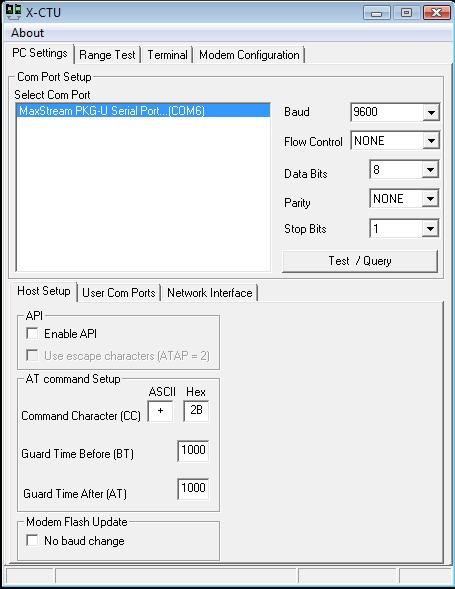
17 Serial Terminal Programs X-CTU: pid=3352&osvid=57&tp=4&s=316 CoolTerm: HyperTerm: Windows Start Menu, Accessories, Communication screen: Terminal program on the Mac (or Linux) plenty of others! settings: 9600 baud, 8 bits, no parity, one stop bit, no flow control
18 Addressing
19 Addressing Basics channels PAN ID 64 bit addresses (SN) 16 bit addresses
20 Basic Configuration
21 Download and Install Software & Drivers Download & install the FTDI USB drivers: Download the CoolTerm: Other Serial Terminal Options: settings: 9600 baud, 8 bits, no parity, one stop bit, no flow control X-CTU: Z-Term: HyperTerm: Windows Start Menu, Accessories, Communication Screen: Terminal program on the Mac (or Linux)
22 Open CoolTerm
23 Set Connection Options
24 Configure your radio with AT commands Configure your radio
25 Baud, Bits and Parity Baud rate: 9600 Data bits: 8 Stop bits: 1 Parity: None Flow control: none for now...
26 Data Mode vs. Command Mode Idle Mode, transmit and receive data Command Mode, talk to the XBee itself +++ "Yo, XBee" AT "Attention!" (Hayes command set) always press enter after AT commands never press enter after +++
27 AT Commands
28 Some AT Commands AT -> OK ATMY -> my address ATDH, ATDL -> destination address hi/lo ATID -> personal area network ID ATCN -> end command mode ATWR -> write configuration to flash memory ATRE -> reset to factory defaults
29 Addressing In-Depth SL, SH: fixed serial number address MY: configured local 16 bit address DH, DL: destination address low and high ID: Personal Area Network ID Broadcast FFFF Broadcast PAN FFFF
30 API Mode Powerful, steeper learning curve Data wrapped together with commands, addressing and status information

31 API Mode Format *ATNJ = node join
32 Assignment Pick a PAN ID now and document it. 0 - FFFE okay
33 Basic Chat
34 Create a Basic Pair Two radios Use the 16-bit addresses for destinations HANDOUT Remember, the radios work reliably, troubleshooting is mostly about figuring out what they re doing.

35 Ding, Dong!
36 Basic Doorbell XBee Direct: no external microcontrollers: 1. doorbell switch connected to an XBee radio 2. buzzer connected to another XBee radio sounds the alert 3. someone s at the door!
37 Background
38 I/O Intro For simple input and/or output Eight digital input/outputs One additional digital output Seven analog inputs Two analog outputs But not all at once! Pins are shared.
39 I/O Why Why: Save space, save power, save weight and save money Reduce complications for simple projects Why not: Limited inputs/outputs No access to logic Might make complicated projects even more complicated

40 Input/Output Wiring : Basic Breakout
41 Input/Output Wiring : Parallax XBee USB = I/O pin Analog In Ground +3.3V Transmit Receive Voltage Reference PWM Out +V in Ground
42 Indicator Lights: Parallax XBee USB LED FUNCTIONS: Yellow Power Green ON (not sleeping) Blue RSSI (receive data) Red Association Indicator The USB connector also has two LEDs which indicate TX / RX status: Red - transmit to the PC Green - receive from the PC
43 I/O AT Commands ATD0...D8 -> configure pins for I/O ATIR -> sample rate ATIT -> samples before transmit ATP0...P1 -> PWM configuration ATIA -> I/O input address
44 Setting I/O Pins ATDx 0 Disabled ATDx 1 Built-in Function (sometimes) ATDx 2 Analog Input (sometimes) ATDx 3 Digital Input ATDx 4 Digital Output, low to start with ATDx 5 Digital Output, high to start with...so ATD32 would do what?
45 Basic Doorbell Project
46 Button Schematic


47 Button Breadboard
48 Buzzer Schematic

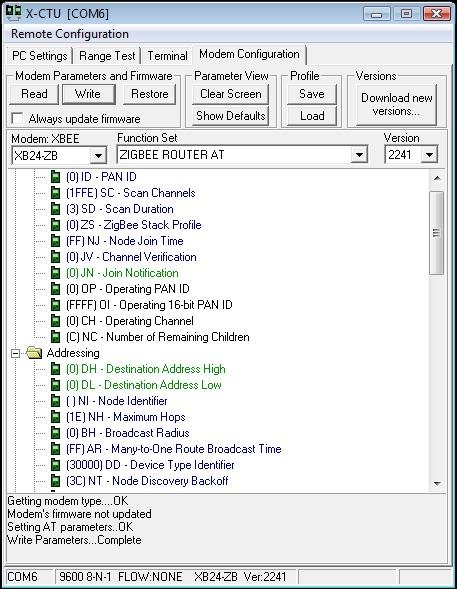
49 Buzzer Breadboard
50 Setup Strings Button XBee: ATRE,ID3001,MY1,DL2,IR64,IT1,D03,IAFFFF,WR Buzzer XBee: ATRE,ID3001,MY2,DL1,IR64,IT1,D05,IAFFFF,WR *** be sure to change 3001 to your own PAN ID!!
51 Addressing ATRE resets to factory settings ATID sets the PAN ID (choose your own) ATMY sets the local radio s address ATDL sets the destination address
52 Input/Output Settings ATIR sets the data sample rate (uses hexadecimal notation) ATIT how many samples transmitted at a time ATD0 mode for digital pin zero (3=digital input, 5=digital output) ATIA remote address that s allowed to control local pins ATWR writes the settings to firmware (like saving to a disk)

53 CoolTerm
54 More Got it already? Try going the other way: a light for I ll be right there feedback. remember that input and output pins are paired and mirrored Use analog: how loud to ring (use light to simulate if needed) ATD02 sets for analog inputs analog outputs come from PWM pins ATP0 & ATP1, so paired but not mirrored with inputs
55 ZigBee Addressing
56 ZigBee Coordinator Every ZigBee network must have a coordinator There can only be one coordinator Coordinator selects channel and PAN ID End devices and routers can then join the PAN Typically mains-powered Coordinator s 16-bit address is always 0
57 ZigBee Router Non-coordinator routers are optional to ZigBee networks Typically mains-powered Many can be on each PAN Issues a beacon request on startup to locate channel and PAN Routers can communicate with any device on the network Stores packets for sleeping end devices 16-bit address assigned by coordinator
58 ZigBee End Device Optional to ZigBee networks Typically battery-powered Many can be on each PAN Issues a beacon request on startup to locate channel, PAN and parent End devices can only communicate directly with their parent 16-bit address assigned by coordinator

59
 and two power levels, regular and Pro and 4 antennas!")
60 XBee ZB Coordinator Firmware for AT commands or API Router and End Device Firmware for AT commands or API...so 6 different firmware combinations (you ll always use 2 at the same time) and two power levels, regular and Pro and 4 antennas! whip, chip, U.FL and RPSMA.
61 Addressing Basics channels PAN ID 64 bit addresses (SN) 16 bit addresses
62 Firmware Updates
63

64
65
66 Basic Configuration
67 Download and Install Software & Drivers Download & install the FTDI USB drivers: Download the CoolTerm: Other Serial Terminal Options: settings: 9600 baud, 8 bits, no parity, one stop bit, no flow control X-CTU: Z-Term: HyperTerm: Windows Start Menu, Accessories, Communication Screen: Terminal program on the Mac (or Linux)

68 Open CoolTerm

69 Set Connection Options
70 Configure your radio with AT commands Configure your radio
71 AT Commands
72 Some AT Commands AT -> OK ATDH, ATDL -> destination address hi/lo ATID -> personal area network ID ATCN -> end command mode ATWR -> write current configuration to firmware ATMY -> my address NOT SETTABLE FOR ZIGBEE ATRE -> reset to factory defaults
73 Pair Exercise
74 Create a Basic ZigBee Pair One coordinator and one router Use the 64-bit addresses for destinations ATNR will reset your network layer, useful if you join the wrong ID Remember, the radios work reliably, troubleshooting is mostly about figuring out what they re doing.
75 ZigBee and Arduino
76 Why Arduino local logic pinouts fast prototyping one side of I/O
77 Arduino Serial Library Serial.begin(speed) Serial.available() Serial.read() Serial.flush() Serial.print(data)
78 Software Serial 115K baud max, all pins are okay to use, all functions available buffering! good choice for input when you want debug on the HW port for ease-of-use in versions prior to Arduino 1.0 use:
79 Breadboard Hookups
80 Wiring +3.3 V transmit receive ground

81 XBee Arduino Breadboard Layout

82 Power, Ground

83 TX, RX

84 XBee Connections (pin 1, 2, 3 and 10)
85 Remember! Use only +3.3 Volts. More than +7 Volts will kill your radio If you use a voltage regulator, always use decoupling capacitors. The radios often don t work without them. XBee TX goes to Arduino RX and vice versa. Unplug the TX & RX before uploading Arduino code (or use switches) You can t send infinitely fast. Try putting a 10 ms delay into your loop.
86 I/O Mode
87 I/O Intro: ZigBee For simple input and/or output Ten digital input/outputs Four analog inputs No analog outputs on ZigBee But not all at once! Pins are shared.
88 I/O Why Why: Save space, save power, save weight and save money Reduce complications Why not: Limited inputs/outputs No access to logic No analog output on ZigBee radios
89 Input/Output Wiring: ZigBee Analog in Voltage reference is optional +3.3 V transmit receive No PWM out! Ground I/O pins
90 Input/Output Wiring ZigBee: Parallax XBee USB = I/O pin Analog In Ground +3.3V Transmit Receive +V in Ground
91 I/O AT Commands: ZigBee ATD0...D7 -> configure pins for I/O (D8 and D9 not supported yet) ATP0...P1 -> configure pins for I/O (P3 not supported yet) ATIR -> sample rate samples before transmit is always 1 destination address receives sample info ALL PINS READ BETWEEN 0 AND 1.2 VOLTS ONLY
92 Settting I/O Pins ATDx 0 Disabled ATDx 1 Built-in Function (sometimes) ATDx 2 Analog Input (sometimes) ATDx 3 Digital Input ATDx 4 Digital Output, low to start with ATDx 5 Digital Output, high to start with...so ATD43 would set what?
93 XBee ZigBees inputs are 1.2V range
94 Voltage Divider to map 3.3V range to 1.2V range
95 API Mode Overview


96 API Mode Application Programming Interface An application programming interface (API) is a source code interface that an operating system or library provides to support requests for services to be made of it by computer programs. XBees in API mode are ready to talk to computers and microcontrollers structured predictable reliable
97 API Structure Used in serial communications with the XBee radio Frames of data envelope structure contains data with metadata inside a constrained format Radio must be in API Mode AT command ATAP 1 on Series 1 radios API firmware on Series 2 radios
98 Why API Rather than: delay(1100); // put the XBee in command mode Serial.print("+++"); delay(1100); if (checkfor("ok", 1000)) { Serial.println("ATID7777,CN"); if (checkfor("ok", 1000)) { // if an OK was received then continue debugprintln("setupok"); success = true; } } With a library you just write: sendcommand(id,0x7777);

99 Envelope Has: From address, to address, outside, inside, size, contents, error check
100 API Basic Frame Envelope
101 Start Byte 0x7E --> also known as the tilde in ASCII: ~ First thing to do is look for it: // ARDUINO VERSION: if (Serial.available() > 0) { // if a byte is waiting in the buffer inbyte = Serial.read(); // read a byte from the buffer if (inbyte == 0x7E) { // we re at the start of an API frame! // add more code here } } // PROCESSING VERSION: if (port.available() > 0 { int inbyte = port.read(); if (inbyte == 0x7E) { // we re at the start of an API frame! // add more code here }
102 Length Bytes MSB: the Most Significant Byte the big part of the number LSB: the Least Significant Byte the small part of the number bit shift MSB to the right and add it to LSB // PROCESSING VERSION: int lengthmsb = port.read(); // high byte for length of packet int lengthlsb = port.read(); // low byte for length of packet int lengthtotal = (lengthmsb << 8) + lengthlsb; // bit shift and add for total
103 API Identifier Specifies the remaining structure of the frame modem status: 0x8A AT command (immediate): 0x08 AT command (queued): 0x09 AT command response: 0x88 TX request: 0x10 TX status response: 0x8B RX packet: 0x90 RX packet I/O data: 0x92 // PROCESSING VERSION: int API_ID = port.read(); // API Identifier indicates type of packet received
104 Identifier-specific Data Structures are different for each API identifier and might include: addressing information (333B) status information (received OK) source information (broadcast packet) unstructured data ( Hello World, this is Rob! ) structured data (typically for I/O packets)
105 Checksum Simple check to detect errors To calculate: Not including frame delimiters and length, add all bytes keeping only the lowest 8 bits of the result and subtract from 0xFF. To verify: Add all bytes (include checksum, but not the delimiter and length). If the checksum is correct, the sum will equal 0xFF. // PROCESSING VERSION: int localchecksum = (API_ID + addrmsb + addrlsb + RSSI + options + datasum); int checksum = port.read(); localchecksum = byte(0xff -localchecksum); if ( (byte) checksum - localchecksum == 0) { returnval = dataadc[0]; } else { print("\n\nchecksum error! " + "\n\n"); }

106 Many Kinds of Envelopes
107 Modem Status: ZigBee

108 AT Command
109 AT Response Frame ID for the response is the same as the matching AT Command request
110 More API
111 TX (Transmit) Request Remember that this is a request. Results can be checked by Frame ID

112 TX Status (Results) See if your message was transmitted or not Use your Frame ID to see which message is being described
113 RX Packet Maximum of 72 bytes of data per packet RF Data section is basis for I/O packets
114 I/O RX Packet


115 I/O Digital Channel Mask and Digital Data


116 I/O Analog Channel Mask and Analog Samples
117 I/O Structure Reviewed Num Samples (1 byte) Digital Channel Mask (2 bytes) Analog Channel Mask (1 byte) Two bytes of digital data IF ANY DIGITAL CHANNELS ENABLED followed by......two bytes for EACH analog channel enabled... Q: How many bytes ATD02 ATD12 ATD23?
118 I/O Bytes Example 0x7E (start byte) 0x00 0x17 (length) 0x92 (API id) 0x00 (64-bit address) 0x13 0x20 0x00 0x43 0x23 0x12 0xEF 0x03 (16-bit address) 0xA4 0x01 (num samples) 0x00 (digital channel masks) 0x00 0x01 (analog channel mask) 0x02 (first analog sample) 0xF8 0x30 (the checksum)
119 I/O Code: Basic Fixed parameters make for easier programming Assume we are just reading a single ADC channel: Arduino Version: // make sure everything we need is in the buffer if (Serial.available() >= 21) { // look for the start byte if (Serial.read() == 0x7E) { // read the variables that we're not using out of the buffer for (int i = 0; i<18; i++) { byte discard = Serial.read(); } int analoghigh = Serial.read(); int analoglow = Serial.read(); analogvalue = analoglow + (analoghigh * 256); } }
120 Simple Sensor Network

121 API and a Sensor Network

122 Simple Sensor Network
123
MIT Media Lab: XBee Workshop. Instructor: Rob Faludi
 MIT Media Lab: XBee Workshop Instructor: Rob Faludi Plan for Today XBees Serial Terminals Addressing Basic Config Chat Project I/O Mode Arduino & XBee Workshop, Q&A Student Introductions Name, where you
8/11/11. Radio Communication Configurations Zigbee Configurations. Zigbee. XBee Wireless
 Radio Communication XBee Wireless Michelle Shorter 802.15.4 Low Power Low bandwidth Addressing Affordable Small Standardized Popular Electromagnetic Waves No medium required Modulation Well described mystery
XBee Wireless. Michelle Shorter
 XBee Wireless Michelle Shorter Radio Communication Electromagnetic Waves No medium required Modulation Well described mystery Wireless/Airwaves Inverse Square Law 802.15.4 Low Power Low bandwidth Addressing
Sociable Objects Workshop. Instructor: Rob Faludi
 Sociable Objects Workshop Instructor: Rob Faludi Plan for Today Final Projects Class in Review Readings & Assignments Final Project Presentations Class in Review Introduction Sociable Objects Connections
ZigBee Wireless. Thursday, October 12th, 9:15 pm Room 447
 DriveBy: ZigBee Wireless Thursday, October 12th, 9:15 pm Room 447 Discover the joy of moving data wirelessly using ZigBee radios. You'll learn how to install and configure XBee brand radios to link up
Collaborative Mesh Networking. Instructor: Rob Faludi Week 9
 Collaborative Mesh Networking Instructor: Rob Faludi Week 9 ZigBee Mesh Project Presentation of mobile mesh project ideas for each group Readings Startup eyes battery-free wireless sensor nets: http://eetimes.eu/
Rob Faludi, 8/17/11
 Horsie Race This project can serve as a model for almost any many-to-one network you d like to build. You will create a carnival midway-style horse race using a wireless audio input that transmits each
L13. Communicating wireless by XBee modules
 L13. Communicating wireless by XBee modules 1. Introduction XBee and XBee-PRO ZB embedded RF modules provide cost-effective wireless connectivity to devices in ZigBee mesh networks. With the PRO Feature
1 of 4 1/23/ :17 AM
 1 of 4 1/23/2012 10:17 AM Wireless Proto Shield Front Overview The Wireless Proto shield allows an Arduino board to communicate wirelessly using a wireless module. It is based on the Xbee modules from
Figure 3-1: XBee Loopback Testing
 3: XBee Testing & Configuration Communications between the PC and XBee can be an integral part of your system whether for XBee configuration, monitoring and control of a device, or simply for testing and
XBee /XBee-PRO OEM RF Modules
 XBee /XBee-PRO OEM RF Modules XBee/XBee-PRO OEM RF Modules ZigBee Networks RF Module Operation RF Module Configuration Appendices Product Manual v8.x1x Beta - ZigBee Protocol For OEM RF Module Part Numbers:
Mesh networking with ZigBee. A dive into the ZigBee ecosystem
 Mesh networking with ZigBee A dive into the ZigBee ecosystem Agenda THEORETICAL PART What is ZigBee ZigBee Networking ZigBee Application Support ZigBee Security PRACTICAL PART XBee intro Exercise A Exercise
IO Expansion Shield User Manual
 IO Expansion Shield User Manual 1 Features 3-pin & 4-pin sensor interfaces, supports connecting sensors directly without complicate custom connections XBee module connector WIFI-LPT100 wireless module
XBee Series 2 OEM RF Modules
 XBee Series 2 OEM RF Modules XBee Series 2 OEM RF Modules ZigBee Networks RF Module Operation RF Module Configuration Appendices Product Manual v1.x.1x - ZigBee Protocol For OEM RF Module Part Numbers:
The BASIC Stamp and other 5 V controllers need an adapter that:
 The XBee module is a 20 pin DIP package with a pitch of 2 mm (0.079 in) between pins. With typical breadboard and solder board hole spacing of 2.54 mm (0.1 in) the XBee requires an adapter for use with
Application Note for Configuring XBee S1 Modules Using CoolTerm on Mac OSX
 Application Note for Configuring XBee S1 Modules Using CoolTerm on Mac OSX Introduction: This tutorial demonstrates how to configure the 2 XBee modules: one for transmitting and one for receiving using
XBee ZigBee Mesh Kit Radio Frequency (RF) Module. User Guide
 Module. User Guide") XBee ZigBee Mesh Kit Radio Frequency (RF) Module User Guide Revision history 90001942-13 Revision Date Description S May 2015 Update the SMT dimensions drawing. Added a section on deep sleep and sleep
XBee ZigBee Mesh Kit Radio Frequency (RF) Module User Guide Revision history 90001942-13 Revision Date Description S May 2015 Update the SMT dimensions drawing. Added a section on deep sleep and sleep
ARDUINO WIRELESS SD SHIELD Code: A000065
 ARDUINO WIRELESS SD SHIELD Code: A000065 The Wireless SD shield allows an Arduino board to communicate wirelessly using a wireless Xbee module or similar plus a micro SD card slot OVERVIEW The Wireless
Sierra Radio Systems. Mesh Data Network. Reference Manual. Version 1.0
 Sierra Radio Systems Mesh Data Network Reference Manual Version 1.0 Contents Hardware Xbee backpack board Xbee base station Xbee firmware configuration RS485 network power injector Protocol specification
Dual Serial Shield User Manual
 Dual Serial Shield User Manual PN: 2050 Berkshire Products, Inc. Phone: 770-271-0088 http://www.bkp-store.com/ Rev: 1.00 Copyright 2013 Table of Contents 1 Introduction... 2 1.1 XB compatibility... 2 2
Example: Enable sleep mode
 Example: Enable sleep mode In this example, you will learn how to extend the battery life of an XBee ZigBee module. The example uses all three modules included in the kit to demonstrate how a ZigBee network
Arduino & mbed Workshop + Hackathon
 Arduino & mbed Workshop + Hackathon Rob Faludi! Arduino Basics Pedro Perez! Intro to mbed Goals Explore two paths to fast programmability with our radio modules in mind Learn their strengths and weaknesses
XBee ZigBee SMT RF Module Development Kit Getting Started Guide
 XBee ZigBee SMT RF Module Development Kit Getting Started Guide 90002013_D 5/8/2013 2013 Digi International Inc. All rights reserved. Digi, Digi International, the Digi logo, the Digi web site, a Digi
By Ambuj Varshney & Akshat Logar
 By Ambuj Varshney & Akshat Logar Wireless operations permits services, such as long range communications, that are impossible or impractical to implement with the use of wires. The term is commonly used
XBee-PRO 900HP DigiMesh Kit
 XBee-PRO 900HP DigiMesh Kit Radio Frequency (RF) Module User Guide Revision history 90001496 Revision Date Description A January 2016 Initial release. B March 2016 Rebranded with minor updates. Trademarks
Note. The above image and many others are courtesy of - this is a wonderful resource for designing circuits.
 Robotics and Electronics Unit 2. Arduino Objectives. Students will understand the basic characteristics of an Arduino Uno microcontroller. understand the basic structure of an Arduino program. know how
MeshX [Firmware Version 801(x)] MaxStream Wireless Mesh Networking
![MeshX [Firmware Version 801(x)] MaxStream Wireless Mesh Networking](/thumbs/78/77360034.jpg "MeshX [Firmware Version 801(x)] MaxStream Wireless Mesh Networking") MeshX [Firmware Version 801(x)] MaxStream Wireless Mesh Networking Introduction 2 MeshX Feature Set 2 Communications 3 Transparent Operation 3 API Operation 3 Data Transmission 4 Unicast Addressing 4 Broadcast
MeshX [Firmware Version 801(x)] MaxStream Wireless Mesh Networking Introduction 2 MeshX Feature Set 2 Communications 3 Transparent Operation 3 API Operation 3 Data Transmission 4 Unicast Addressing 4 Broadcast
Introduction. Introduction
 Introduction Introduction As researchers and teachers at Southern Illinois University Carbondale (SIUC) in Electronics Systems Technologies (EST), we have used the Series 1 XBee extensively in the classroom
In this activity you will create a tool to allow you to play games such as Red Light/Green Light. To create the game, follow the steps below.
 Example: Hello World In this activity you will create a tool to allow you to play games such as Red Light/Green Light. To create the game, follow the steps below. If you get stuck, go to the Troubleshooting
XBee transparent mode
 XBee transparent mode When operating in transparent mode, the modules act as a serial line replacement. That is, all data received through the serial input is immediately transmitted over the air, and
Arduino Prof. Dr. Magdy M. Abdelhameed
 Course Code: MDP 454, Course Name:, Second Semester 2014 Arduino What is Arduino? Microcontroller Platform Okay but what s a Microcontroller? Tiny, self-contained computers in an IC Often contain peripherals
GETTING STARTED GUIDE
 Drop-in Networking GETTING STARTED GUIDE Drop-in Networking 90000873-88_B Digi International Inc.2007. All Rights Reserved. Digi, Digi International, the Digi logo, ConnectPort, Watchport, and XBee, are
RFD900x Asynchronous firmware
 RFD900x Asynchronous firmware User Manual Configuration and usage guide Flash Programmer User Manual RFDesign Pty Ltd 7/1 Stockwell Place Archerfield, QLD 4108 rfdesign.com.au Table of contents 1 Introduction...
I, J, K. Ethernet.begin() method, 274. Future Technology Devices International (FTDI), 24
 method, 274. Future Technology Devices International (FTDI), 24") Index A Analog to digital converters (ADCs), 181 Application programming interface (API), 170 Arduino clone boards (see Arduino clones) components list, 96 DHT22 sensor error code, 76 hardware setup, 75
Index A Analog to digital converters (ADCs), 181 Application programming interface (API), 170 Arduino clone boards (see Arduino clones) components list, 96 DHT22 sensor error code, 76 hardware setup, 75
Comparing the Digi XBee API with EmberZNet EM260 API
 Comparing the Digi XBee API with EmberZNet EM260 API White Paper Abstract Digi s XBee ZB module and the EM260 co-processor are similar in many respects. Both are designed to provide an interface to a ZigBee
USB ZigBee Adapter. User Manual. 1.0, Dec 2011
 USB ZigBee Adapter User Manual 1.0, Dec 2011 This work is licensed under the Creative Commons Attribution-Share Alike 2.5 India License. To view a copy of this license, visit http://creativecommons.org/licenses/by-sa/2.5/in/
Xbee module configuration from a µcontroller
 APPLICATION NOTE AN_P12AB04_1 Xbee module configuration from a µcontroller Soulier Baptiste Polytech Clermont Ferrand 2012-2013 The purpose of this application note is to explain how to configure the main
XBee ZNet 2.5/XBee-PRO ZNet 2.5 OEM RF Modules
 XBee ZNet 2.5/XBee-PRO ZNet 2.5 OEM RF Modules XBee ZNet 2.5/XBee PRO Znet 2.5 OEM RF Modules ZigBee Networks RF Module Operation RF Module Configuration Appendices Product Manual v1.x.4x - ZigBee Protocol
1. Features. 2. Applications. 3. Description. Low Energy ZigBee module RF5168 RF GHz Low Energy ZigBee Module V1.
 RF5168 2.4-GHz Low Energy ZigBee Module V1.10 1. Features Frequency Range: 2405~2480MHz UART Data Interface Sensitivity: -104dBm Output Power: 20dBm High efficient coding & Frequency hopping High anti-interferences
ESPino - Specifications
 ESPino - Specifications Summary Microcontroller ESP8266 (32-bit RISC) WiFi 802.11 (station, access point, P2P) Operating Voltage 3.3V Input Voltage 4.4-15V Digital I/O Pins 9 Analog Input Pins 1 (10-bit
RoboticsConnection XBee Connection Guide. Summerour Robotics Guide V1.1
 RoboticsConnection XBee Connection Guide Summerour Robotics Guide 2 3 2009 V1.1 Introduction The purpose of this guide is to assist customers in configuring, and establishing a connection between two XBee
User s Manual Closer to Real, Zigbee Module ZIG-100. Wireless Communication. ROBOTIS CO.,LTD
 User s Manual 2006-07-06 Closer to Real, Wireless Communication ROBOTIS CO.,LTD. www.robotis.com +82-2-2168-8787 Contents 1. Page 02 2. Zigbee Setting Page 06 3. PC Interface Zig Board Schematic Page 10
XBee Starter Kit Getting Started Guide
 XBee 802.15.4 Starter Kit Getting Started Guide 90002160_A 6/20/2012 2012 Digi International Inc. All rights reserved. Digi, Digi International, the Digi logo, the Digi web site, a Digi International Company,
Adafruit Metro Mini. Created by lady ada. Last updated on :12:28 PM UTC
 Adafruit Metro Mini Created by lady ada Last updated on 2018-01-24 08:12:28 PM UTC Guide Contents Guide Contents Overview Pinouts USB & Serial converter Microcontroller & Crystal LEDs Power Pins & Regulators
AppBee-Mod & AppBee-SIP Documentation for use with the BASIC Stamp
 AppBee-Mod & AppBee-SIP Documentation for use with the BASIC Stamp Application Interface Boards for the ZigBee / IEEE 802.15.4 XBee and XBee-PRO Wireless Network Transceivers Document Revision 4. Device
Device: FDRV-04S. This document version: v1. Matches module version: v2 [2 Oct 2015] Document revision date: 9 November 2015
![Device: FDRV-04S. This document version: v1. Matches module version: v2 [2 Oct 2015] Document revision date: 9 November 2015](/thumbs/93/113411552.jpg "Device: FDRV-04S. This document version: v1. Matches module version: v2 [2 Oct 2015] Document revision date: 9 November 2015") Device: FDRV-04S This document version: v1 Matches module version: v2 [2 Oct 2015] Document revision date: 9 November 2015 Description: I2C 4 Device Motor / Solenoid Driver Board FDRV-04S HWv2 datasheet
Device: FDRV-04S This document version: v1 Matches module version: v2 [2 Oct 2015] Document revision date: 9 November 2015 Description: I2C 4 Device Motor / Solenoid Driver Board FDRV-04S HWv2 datasheet
XBee-PRO 900HP Development Kit Getting Started Guide
 XBee-PRO 900HP Development Kit Getting Started Guide 90002172_A 7/26/2012 2012 Digi International Inc. All rights reserved. Digi, Digi International, the Digi logo, the Digi web site, a Digi International
XBee-PRO PKG-U USB RF Modem
 XBee-PRO PKG-U USB RF Modem XBee-PRO USB RF Modem RF Modem Operation RF Modem Configuration Appendices Product Manual v1.xax For XBee-PRO RF Modem Part Numbers: XBP24-PKC-...-U... IEEE 802.15.4 Boxed USB
Serial Basic Hookup Guide
 Page 1 of 7 Serial Basic Hookup Guide Introduction The Serial Basic is an easy to use USB to Serial adapter based on the CH340G IC from WCH. It works with 5V and 3.3V systems and should auto install on
um-fpu Application Note 9 Adding a Serial Connection to um-fpu V2
 um-fpu Application Note 9 Adding a Serial Connection to um-fpu V2 This application note describes various methods of adding a serial connection to the um-fpu to provide support for debugging um-fpu code
RedBoard Hookup Guide
 Page 1 of 11 RedBoard Hookup Guide CONTRIBUTORS: JIMB0 Introduction The Redboard is an Arduino-compatible development platform that enables quick-and-easy project prototyping. It can interact with real-world
Determination of Optimal Power for ZigBee-based Wireless Sensor Networks
 University of Windsor Scholarship at UWindsor Electronic Theses and Dissertations 2014 Determination of Optimal Power for ZigBee-based Wireless Sensor Networks Okhamila Yusuf University of Windsor Follow
CEL MeshConnect ZICM35x Test Tool User Guide
 User Guide 0011-00-17-02-000 CEL MeshConnect ZICM35x Test Tool User Guide CEL MeshConnect ZICM35x Test Tool User Guide Introduction CEL s MeshConnect EM357 Mini Modules combine high performance RF solutions
Lab 1: An Introduction to Arduino: From Flashing Lights to a Wireless Robot!
 : From Flashing Lights to a Wireless Robot! During the relatively short and time consuming first few weeks of class, we will be working to get you familiar with a number of different platforms and tools.
G3P-WiFi User Manual Release 1.2
 G3P-WiFi User Manual Release 1.2 Last Update 25/11/2014 1 Appendix Order Codes... 3 Release History... 3 Release 1.0... 3 Release 1.1... 3 Release 1.2... 3 GENERAL FEATURES... 3 1 Tools to begin... 4 1.1
USB Wireless Bridge USERS MANUAL R02
 USB Wireless Bridge USERS MANUAL R02 Contents Overview... 3 Specifications... 3 Performance... 3 Power Requirements... 4 Mechanical... 4 Pinout and Wiring... 5 Operation... 5 Standard Operation... 5 LED
Lesson 5 Arduino Prototype Development Platforms. Chapter-8 L05: "Internet of Things ", Raj Kamal, Publs.: McGraw-Hill Education
 Lesson 5 Arduino Prototype Development Platforms 1 Arduino Boards, Modules And Shields Popular AVR MCU based products Each board has clear markings on the connection pins, sockets and in-circuit connections
1/Build a Mintronics: MintDuino
 1/Build a Mintronics: The is perfect for anyone interested in learning (or teaching) the fundamentals of how micro controllers work. It will have you building your own micro controller from scratch on
XBee-PRO PKG-R RS-232 RF Modem
 XBee-PRO PKG-R RS-232 RF Modem XBee-PRO RS-232 RF Modem Interfacing Protocol RF Modem Operation RF Modem Configuration Appendices Product Manual v1.xax For XBee-PRO RF Modem Part Numbers: XBP24-PKI-...-R...
Quick guide for configuring a system with multiple IP-LINKs
 Quick guide for configuring a system with multiple IP-LINKs October 4 th 2005, KK. This guide will show an example configurations for a system with multiple IP-LINKs. Example 1, three devices connected
What s in the box. Connection Please see also a video tutorial at https://youtu.be/eeeutrlq8bw. Securing wire. 4 pin adapter.
 FPV1 Zaggometry Naza2FrSky Taranis Telemetrie-Adapter Page 1 of 12 What s in the box 4 pin adapter Securing wire 3 pin adapter S.Port connector Connection Please see also a video tutorial at https://youtu.be/eeeutrlq8bw
Goal: We want to build an autonomous vehicle (robot)
") Goal: We want to build an autonomous vehicle (robot) This means it will have to think for itself, its going to need a brain Our robot s brain will be a tiny computer called a microcontroller Specifically
Goal: We want to build an autonomous vehicle (robot) This means it will have to think for itself, its going to need a brain Our robot s brain will be a tiny computer called a microcontroller Specifically
The MMDVM Specification ( )
") The MMDVM Specification (20150922) Introduction The MMDVM is intended to be an open-source Multi-Mode Digital Voice Modem, which utilises the power of an ARM processor and a simple analogue interface board.
The MMDVM Specification (20150922) Introduction The MMDVM is intended to be an open-source Multi-Mode Digital Voice Modem, which utilises the power of an ARM processor and a simple analogue interface board.
TA0139 USER MANUAL ARDUINO 2 WHEEL DRIVE WIRELESS BLUETOOTH ROBOT KIT
 TA0139 USER MANUAL ARDUINO 2 WHEEL DRIVE WIRELESS BLUETOOTH ROBOT KIT I Contents Overview TA0139... 1 Getting started: Arduino 2 Wheel Drive Wireless Bluetooth Robot Kit using Arduino UNO... 1 2.1. What
RN-WIFLY-EVAL-UM. WiFly Evaluation Kit Roving Networks. All rights reserved. RN-WIFLY-EVAL-UM-1.0 Version /8/2011 USER MANUAL
 RN-WIFLY-EVAL-UM WiFly Evaluation Kit 0 Roving Networks. All rights reserved. RN-WIFLY-EVAL-UM-.0 Version.0 //0 USER MANUAL OVERVIEW This document describes the hardware and software setup for Roving Networks
1. General Description
 1. General Description HPTZ01X (HPTZ01-TTL,HPTZ01P-TTL)Serial ZigBee module is development designed by Ember ZigBee chip EM35x. It is a module base on IEEE 802.15.4-2003 standard for the 2.4G ISM band.
NATIONAL CONTROL DEVICES Fusion Reactor Quick Start Guide
 NATIONAL CONTROL DEVICES Fusion Reactor Quick Start Guide N A T I O N A L C O N T R O L D E V I C E S Fusion Reactor Quick Start Guide National Control Devices, LLC PO Box 455 Osceola, MO 64776 Phone 417.646.5644
XBee Drop-in Networking Accessories User s Guide
 XBee Drop-in Networking Accessories User s Guide XBee RS-232 Adapter XBee RS-485 Adapter XBee Analog I/O Adapter XBee Digital I/O Adapter XBee USB Adapter XStick XBee Wall Router Smart Energy Range Extender
Embit Binary Interface - IEEE Specific Documentation. embit s.r.l.
 Embit Binary Interface - IEEE 802.15.4-Specific Documentation embit s.r.l. Document information Versions & Revisions Revision Date Author Comments 1.0 A. Sala First release 1.1 14/12/2012 C. Biagi Minor
RC1170-RC232 USER MANUAL
 RC1170-RC232 USER MANUAL Overview: Introducing RC11XX-RC232 RF Transceiver boards for the data transmission using RF. Where RC11xx transceiver modules are compact surface-mounted high performance modules
RS232-ADC16/24 Manual
 RS232-ADC16/24 Manual Version 1.11 Copyright taskit GmbH 2009 www.taskit.de Page 1/22 Table of contents 1 Features...3 2 Introduction...3 3 Bringing into service...4 4 Application Sample...5 5 Frame layout...6
DRF1605H Zigbee Module 1.6km Transfer CC2530 Wireless Module UART to Zigbee
 DRF1605H Zigbee Module 1.6km Transfer CC2530 Wireless Module UART to Zigbee Description 100% Brand new The Advantage: 1, NetWork creation automatically: after power on, the Zigbee network can create automatically
IDUINO for maker s life. User Manual. For IDUINO development Board.
 User Manual For IDUINO development Board 1.Overview 1.1 what is Arduino? Arduino is an open-source prototyping platform based on easy-to-use hardware and software. Arduino boards are able to read inputs
USB-I2C USB to I2C Communications Module Technical Specification
 Page 1 of 7 USB-I2C USB to I2C Communications Module Technical Specification The USB-I2C module provides a complete interface between your PC and the I2C bus. The module is self powered from the USB cable
Logosol Joystick Node LS-731
 Features 2 and 3 axis models Travel ±20 deg Non contact hall effect joystick Mechanical MTBF 15,000,000 cycles 3 pushbuttons Up to 2 stick pushbuttons 8 LEDs Member of Logosol s distributed motion control
Introduction to Microcontroller Apps for Amateur Radio Projects Using the HamStack Platform.
 Introduction to Microcontroller Apps for Amateur Radio Projects Using the HamStack Platform www.sierraradio.net www.hamstack.com Topics Introduction Hardware options Software development HamStack project
Figure 1: ZigBee Evaluation Kit (ZEK) Contents. Figure 2: ZigBee Adapter Zb-121 and Module Zb-21
 Contents. Figure 2: ZigBee Adapter Zb-121 and Module Zb-21") The ZigBee Evaluation Kit (ZEK) has been developed for evaluation of the ZigBee wireless solution from Amp ed RF. This demo kit utilizes Amp ed RF ZigBee Serial Adapter (AR Zb-121) board with embedded
The ZigBee Evaluation Kit (ZEK) has been developed for evaluation of the ZigBee wireless solution from Amp ed RF. This demo kit utilizes Amp ed RF ZigBee Serial Adapter (AR Zb-121) board with embedded
RF RF 433MHz Transceiver Module
 RF1100-232 RF 433MHz Transceiver Module I have recently started using the RF1100-232 module in an Arduino based project. I found it really difficult to find any useful detailled information on this module.
ZFSM-201-KIT-1 Wireless UART Application User Guide
 Free Star Pro Series ZFSM-201-KIT-1 Wireless UART Application User Guide ZFSM-201-1 FreeStar Pro Module Document # 0006-00-08-06-000 (Rev A) Table of Contents 1 OVERVIEW... 2 1.1 DESCRIPTION... 2 2 COMMUNICATIONS
Web Site: Forums: forums.parallax.com Sales: Technical:
 Web Site: www.parallax.com Forums: forums.parallax.com Sales: sales@parallax.com Technical: support@parallax.com Office: (916) 624-8333 Fax: (916) 624-8003 Sales: (888) 512-1024 Tech Support: (888) 997-8267
The Unofficial XBee FAQ (version 1.3)
") The Unofficial XBee FAQ (version 1.3) johnf January 30, 2012 1. I m a newbie to XBees. How do I get started? That s a Big Question. Are you committed to a particular model of XBee (perhaps because you
The Unofficial XBee FAQ (version 1.3) johnf January 30, 2012 1. I m a newbie to XBees. How do I get started? That s a Big Question. Are you committed to a particular model of XBee (perhaps because you
DEMO XTR-8LR100 DEMO XTR-8LR10 User Manual
 0 Picture 1: Demo board XTR-8LR100 Picture 2: Demo board XTR-8LR10 DEMO-BOARD XTR-8LR100 (Picture 1) e DEMO-BOARD XTR-8LR10 (Picture 2) is an evaluation board of the transceiver module XTR-8LR100 and module
XBee /XBee-PRO 900 OEM RF Modules
 XBee /XBee-PRO 900 OEM RF Modules XBee /XBee-PRO 900 OEM RF Modules RF Module Operation RF Module Configuration Appendices OEM RF Modules by Digi International D R A F T Digi International Inc. 11001 Bren
ZigBee / Application Kit
 AN413 ZigBee /802.15.4 Application Kit Introduction The ZigBee /802.15.4 Application Kit combines MaxStream s XBee RF modem with a popular Rabbit- Core module. The XBee modem is mounted on an RF Interface
XBee-PRO PKG-U USB RF Modem
 XBee-PRO PKG-U USB RF Modem 802.15.4 User Guide Revision history 90000831 Revision Date Description A September, 2006 Initial release. B May, 2007 Updated document to fix minor errors. C July, 2017 Updated
XStream AT Commands. Advanced Manual v South 520 West, Suite 180 Lindon, UT Phone: (801) Fax: (801)
 Fax: (801)") XStream AT Commands XStream Product Family Modes of Operation Radio Modem Configuration Advanced Networking and Security Appendices Advanced Manual v4.29 Standard AT Commands Configurations Products Supported:
XStream AT Commands XStream Product Family Modes of Operation Radio Modem Configuration Advanced Networking and Security Appendices Advanced Manual v4.29 Standard AT Commands Configurations Products Supported:
XBEE in API mode PRESENTED BY : NIKUNJ GANDHI ( ) VARUN KUMAR DWIVEDI ( )
 VARUN KUMAR DWIVEDI ( )") XBEE in API mode PRESENTED BY : NIKUNJ GANDHI (200811013) VARUN KUMAR DWIVEDI (200811011) 1 XBEE RADIO S DON T TELL ME ABOUT THE TECHNOLOGY TELL ME ABOUT THE APPLICATION --- TOM 2 WHAT S THE APPLICATION?
XBEE in API mode PRESENTED BY : NIKUNJ GANDHI (200811013) VARUN KUMAR DWIVEDI (200811011) 1 XBEE RADIO S DON T TELL ME ABOUT THE TECHNOLOGY TELL ME ABOUT THE APPLICATION --- TOM 2 WHAT S THE APPLICATION?
User Manual. ESP8266 Wifi Shield
 User Manual Of ESP8266 Wifi Shield Description The shield is designed based on esp8266 by Espressif Systems, pin-compatible with Arduino UNO/Mega2560 DevBorad. Which can be used as two independent part,
GF167 1 of 16. Download a ZIP file of source code, schematic diagram, and MATLAB files from:
 GF167 1 of 16 THE GADGET FREAK FILES CASE #168 Gas Sensors Sniff Out Danger Natanel Eizenberg decided to build a sensor module that would detect and measure carbon monoxide and methane to help ensure safe
Digi XBee3 DigiMesh. RF Module. Migration Guide
 Digi XBee3 DigiMesh RF Module Migration Guide Introduction Contents Introduction... 3 What s new... 3 Specification considerations... 3 XBee3 Micro options - new to Digi XBee3 DigiMesh... 4 Part number
Propeller Activity Board (#32910)
") Web Site: www.parallax.com Forums: forums.parallax.com Sales: sales@parallax.com Technical: support@parallax.com Office: (916) 624-8333 Fax: (916) 624-8003 Sales: (888) 512-1024 Tech Support: (888) 997-8267
Web Site: www.parallax.com Forums: forums.parallax.com Sales: sales@parallax.com Technical: support@parallax.com Office: (916) 624-8333 Fax: (916) 624-8003 Sales: (888) 512-1024 Tech Support: (888) 997-8267
University of Hull Department of Computer Science C4DI Interfacing with Arduinos
 Introduction Welcome to our Arduino hardware sessions. University of Hull Department of Computer Science C4DI Interfacing with Arduinos Vsn. 1.0 Rob Miles 2014 Please follow the instructions carefully.
4Serial SIK BINDER //77
 4Serial SIK BINDER //77 SIK BINDER //78 Serial Communication Serial is used to communicate between your computer and the RedBoard as well as between RedBoard boards and other devices. Serial uses a serial
XBee Grove Development Board. User Guide
 XBee Grove Development Board User Guide Revision history 90001457-13 Revision Date Description A June 2016 Converted files to new format and completed minor updates to screens and content. B October 2017
Elchin Mammadov. Overview of Communication Systems
 Overview of Communication Systems About Me Studying towards the Masters of Applied Science in Electrical and Computer Engineering. My research area is about implementing a communication framework (software
Lab 01 Arduino 程式設計實驗. Essential Arduino Programming and Digital Signal Process
 Lab 01 Arduino 程式設計實驗 Essential Arduino Programming and Digital Signal Process Arduino Arduino is an open-source electronics prototyping platform based on flexible, easy-to-use hardware and software. It's
keyestudio Keyestudio MEGA 2560 R3 Board
 Keyestudio MEGA 2560 R3 Board Introduction: Keyestudio Mega 2560 R3 is a microcontroller board based on the ATMEGA2560-16AU, fully compatible with ARDUINO MEGA 2560 REV3. It has 54 digital input/output
Base Module Board. Engineering» Design» Product. User Manual. Blue Wolf, Inc W. State Street Garden City, ID 83714
 User Manual Engineering» Design» Product Blue Wolf, Inc. 9179 W. State Street Garden City, ID 83714 Revision History Version # Release Date Revision/Release Comments 1.0 3/14/2011 Initial draft for release.
X Board V2 (SKU:DFR0162)
") X Board V2 (SKU:DFR0162) X-Board V2, DFR0162 Contents 1 Introduction 2 Specifications 3 Pinouts 4 Tutorial 4.1 Requirements 4.2 Wiring Diagram 4.3 Sample code Introduction This is Version 2.0 of the X-board.
X Board V2 (SKU:DFR0162) X-Board V2, DFR0162 Contents 1 Introduction 2 Specifications 3 Pinouts 4 Tutorial 4.1 Requirements 4.2 Wiring Diagram 4.3 Sample code Introduction This is Version 2.0 of the X-board.
Device: MOD This document Version: 1.0. Matches module version: v1. Date: 24 February Description: MP3 Audio Module
 Device: MOD-1021 This document Version: 1.0 Matches module version: v1 Date: 24 February 2014 Description: MP3 Audio Module MOD-1021 v1 datasheet Page 2 Contents Introduction... 3 Features... 3 Connections...