BB 8100 SS Operator s Manual & Troubleshooting Guide
|
|
|
- Caitlin Houston
- 5 years ago
- Views:
Transcription
1
2 FCC NOTICE BB 8100 SS Operator s Manual & Troubleshooting Guide This equipment has been tested and found to comply with the limits for a Class A digital device, pursuant to Subpart J of Part 15 of the FCC Rules. These limits are designed to provide reasonable protection against harmful interference when the equipment is operated in a commercial environment. This equipment generates, uses and can radiate radio frequency energy and, if not installed and used in accordance with the instructions manual, may cause harmful interference to radio communications. Operation of this equipment in a residential area is likely to cause harmful interference in which case the user will be required to correct the interference at his/her own expense. [1]
3 1. CONTENTS 1. CONTENTS INTRODUCTION INSTALLATION Preparation Connections Connecting The Power Supply CONFIGURATION Overview Accessing The Menus Menu Structure Setup Menu Descriptions User Menu Descriptions Exiting The Menus CALIBRATION Calibration Overview Before You Begin Test Weights Zero Calibration (F16) Span Calibration (F17) Calibration Troubleshooting View Calibration Values (F18) Key-In Zero Calibration Value (F19) Key-In Span Calibration Value (F20) FRONT PANEL CONTROLS Display Keypad Primary Function Keys GENERAL SCALE OPERATION Weighing An Item RECHARGEABLE BATTERY INFORMATION [2]
4 8.1 Overview When To Charge The Internal Battery How To Charge The Internal Battery How Long To Charge The Internal Battery Replacing The Battery LEGAL FOR TRADE SEALING SPECIFICATIONS SERIAL PORT INFORMATION Serial Port Modes Demand Duplex Mode Continuous Duplex Mode Recognized Host Commands OUTPUT STRINGS Text Print Ticket ERROR CODES Certificate of Calibration [3]
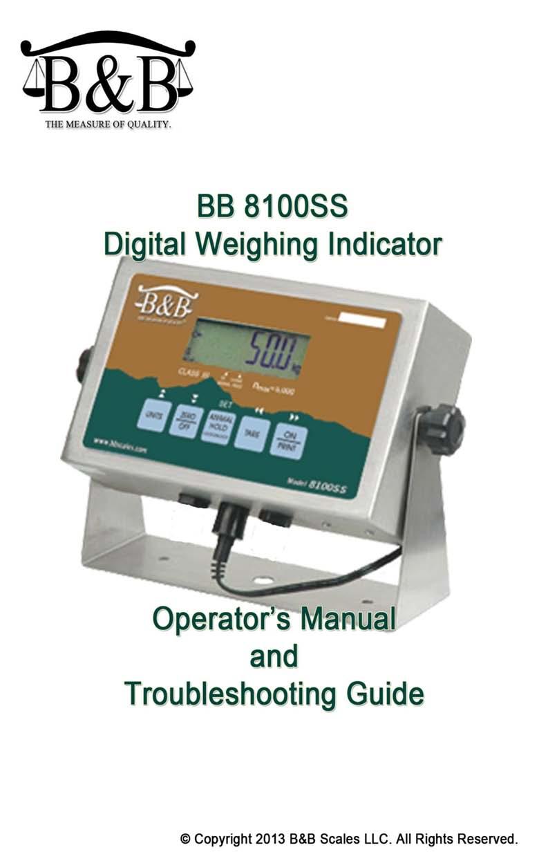
5 2. INTRODUCTION The BB 8100 SS Digital Indicator is a general purpose, industrial grade weight indicator with advanced functionality for weighing animals and other non-stationary objects. One model is currently available, distinguishable by display type, enclosure type and power supply. All models operate identically, can readout up to 50,000 display divisions and can supply enough current for up to Ω load cells. All setup parameters may be entered via the front panel keys, including calibration. If your Model BB 8100 SS Series Digital Indicator is part of a complete floor scale or Weighbeam Scale, it normally arrives fully calibrated and you may skip to the operating instructions. Prior to using the indicator, please read this chapter carefully and completely. Store the manual in a safe and convenient place so it will be available if you have questions concerning the operation of the scale. Model: BB 8100 SS Display: Backlit LCD Enclosure: Stainless Steel Power Source: 12V DC, 800mA A/C Adapter or internal 6V rechargeable battery. [4]
6 3.1 Preparation 3. INSTALLATION Any precision instrument requires a suitable environment in which to operate as intended. Please review each of the following prior to installation: Electrical Power The BB 8100 SS indicator has been designed to operate from 10 to 12 VDC and ships with an AC adapter designed to operate from the local line voltage. To avoid electrical noise interference and/or stray AC electrical transients, try to operate the indicator from a circuit separate from any equipment containing inductive devices such as a contactor coil, solenoid, relay coil, or motor. Be sure to use shielded cables for the load cell connections (ground shield wire at indicator) and run these cables away from your AC/DC power cables if possible. In extreme cases, it may be necessary to install surge suppressors, line conditioners or even UPS (Uninterruptible Power Supplies) systems (not included). Environment - Avoid installing the indicator in areas of direct sunlight or high humidity - Avoid sudden temperature change if this is unavoidable allow equipment to soak at a constant temperature for at least three hours before use - Ensure that steady, clean AC power is available to the unit IMPORTANT: The installer is ultimately responsible to assure that a particular installation is safe and operable under the specific conditions encountered. 3.2 Connections The BB 8100 SS typically comes with two five-pin round quick disconnect ports. In most installations, you will only need to use one of these. It does not matter which port you use; simply plug in the home run cable to one of the two ports and tighten the ring screw to ensure a good connection. In some instances, one of these two ports may be wired to the internal RS-232 port to allow for the connection of a printer or to a computer. This is typically done by special request at the time that you order your scale but is a simple field modification should you desire to modify your indicator. See chapter XREF for more information on modifying indicator ports. 3.3 Connecting The Power Supply The BB 8100 SS indicator ships standard with an external AC adapter that can be used both to operate the unit and charge the internal battery. Simply plug the AC adapter into the indicator s DC Power Jack first, and then plug into a standard wall outlet. [5]
7 IMPORTANT: Make sure that the AC voltage at the wall outlet matches the input voltage marked on the AC adapter. [6]
 menu, which configures the indicator to your weigh platform, and; The User ( A ) menu, which configures the serial")

8 4.1 Overview 4. CONFIGURATION The indicator contains two main configuration menus: The Setup ( F ) menu, which configures the indicator to your weigh platform, and; The User ( A ) menu, which configures the serial communication port and enables some user options. The Setup and User menus consist of several menu selections, each with its own sub-menu of selections or programming procedures. To configure the indicator you must first enter the appropriate menu mode. Once there, four of the front panel keys become directional navigators to move around in the menus, and one key is used to save or SET the selections. 4.2 Accessing The Menus To access the Setup ( F) menu: 1. Power off the indicator. 2. Locate the slide switch on the rear cover and move it to the opposite position. NOTE: A metal plate held on by two drilled-head screws may conceal the slide switch. (In some jurisdictions it is necessary to seal the indicator to place it In Service. These drilled screws allow for a wire to be passed through them and sealed, thereby preventing the indicator from being reprogrammed.) 3. Power on the indicator. The display shows F 1 to indicate that you are in Setup Menu mode. 4. Use the navigation keys shown in the figure below to move through the menus. [7]
 menu until the indicator shows A 1. 4.2.")

9 To access the User ( A) menu: 1. Enter the Setup ( F ) menu as described above. 2. Use the right or left directional keys shown below to move right or left in the Setup ( F ) menu until the indicator shows A Menu Structure All menus consist of a top level (heading) and a secondary level. The top level contains the name of the menus (e.g. F1, F2, F3, etc. ) for the parameter to be configured. The secondary level contains the value for that menu. Use the directional keys to move around in the Menu Structure as shown below. 1. To move to a new heading, use the TARE (left) or ON/PRINT (right) key to move right or left in the Menu. 2. To view or edit the value of a specific F menu, press the ZERO/OFF (down) key once. The currently saved value is shown. 3. To view the other available values for the current value, use the TARE (left) or ON/PRINT (right) key to move through the selection field. 4. To save a new selection, press the ANIMAL HOLD (Set) key.to exit without saving, press the UNITS (up) key to return to the current F menu. 5. Repeat Steps 2 through 5 until the Menu is programmed. 4.3 Setup Menu Descriptions This section provides more detailed descriptions of the selections found in the Setup Menu Chart. Factory-set defaults are shown bold and underlined. IMPORTANT: Some selections are subject to local legal metrology regulations [8]
10 Menu Name F1 Graduations F2 Sampling Rate F3 Zero Track Band F4 Zero Range F5 Motion Band BB 8100 SS Operator s Manual & Troubleshooting Guide Description Specifies number of full-scale graduations, i.e. capacity / division. For example, to program your scale to weigh 5,000lbs you would set this value to 5000, and you would set the value of F9 to 1. To program your scale to weigh 10,000lbs at 2 pound increments, you would set this value to 5,000lbs and you would set F9 to 2. IMPORTANT: Value should be consistent with legal regulations and environmental limits on the useful system resolution. Selects the sampling rate of the indicator. Selections are in samples per second (Hz). Selects the range within which the scale will automatically zero. Note that the scale must be in standstill to automatically zero. Selections are in displayed in divisions (d). Selects the range (expressed as a percentage of full scale capacity) within which the scale may be zeroed. Note that the indicator must be in standstill to zero the scale. Sets the level at which motion is detected. If motion is not detected, the scale can process a Print or Zero command. Maximum value varies depending on local regulations. Expressed as scale divisions per second (d/s). Possible Values 500 1,000 1,500 2,000 2,500 3,000 4,000 5,000 6,000 8,000 10,000 12,000 20,000 30,000 40,000 50,000 10, % 1.9% 2% 20% 0.25, 1,3, 5, 10, 15, 20, 30, 40, 50 F6 Digital Filter F7 Overload Limit F8 Calibration Units Averages weight readings to produce higher stability. The higher the setting, the greater the accuracy but the slower the response time. Choose the speed that works best for your application. Selects the desired formula which determines the point at which the indicator shows overload. All selections are based on the primary unit selected in F8 ("FS" = Full scale capacity) Selects the primary unit of measure to be used in the calibration process. This also sets the default for normal operation. You can switch between Pounds and Kilograms by pressing the UNITS key on the face of the indicator. This setting simply sets the default. "1" = primary unit is lb. "2" = primary unit is in kg. [9] 1, 2, 4, 8, 16, 32 62, 128 FS FS + 2% FS + 1d FS + 9d 1 = Pounds 2= Kilograms
11 Menu Name F9 Display Divisions Description Possible Values Determines the desired weight increments. Value 1 should be consistent with legal requirements. 2 5 F10 Decimal Point Placement F11 Initial Zero Setting Mechanism (IZSM) F12 SmartSense Animal Weighing F16 Zero Calibration F17 Span Calibration F18 View Calibration Settings F19 Zero Calibration Override Sets the decimal point, should you need to weigh in tenths, hundredths, thousandths of pounds, etc. Selects the range (expressed as a percentage of full scale capacity) within which the scale automatically zeroes upon power-up (initialization). If you need the indicator to recall how much weight is on the scale when you first turn on the scale, set this to zero. This is useful for grain carts or other scales that always have weight on them. Sets the percentage change required for the indicator to reset and take a new weight. For example, if two animals accidently jump on the scale and the scale locks at 3500lbs, the scale will automatically reset itself if there is a change in weight of +/- x% of 3500lbs.. When calibrating the scale, set this value to 1 to begin zero calibration. You usually want to make sure there is nothing on your scale before doing this. When calibrating the scale, set this value to 1 to begin Span Calibration. You must place your test weights on the scale prior to beginning this sequence. When the sequence begins you will have an opportunity to enter the amount of weight you are calibrating your scale with. When you calibrate the scale at F16 and F17, the indicator translates the signal from the load cells into a numeric value. There is one numeric value for ZERO pounds, and another numeric value for the amount of weight you used to calibrate the indicator in F17. This menu allows you to view those numeric values. This is VERY useful if you ever need to recalibrate your scale in the field and you do not have test weights. See F19 and F20 for more information. When you calibrated the scale at ZERO pounds in F16, above, the indicator assigned a numeric value to ZERO. You can view the value at F18, above, then enter it here to mimic ZERO calibration. The scale must be calibrated first using F16 before this will work. [10] 0,0.0, 0.00, 0.000, , , 10, 20, 50, 75, 100 (off). Press ZERO/OFF to begin calibration Press ZERO/OFF to begin calibration. Press ZERO/OFF to view values Press ZERO/OFF to begin procedure
12 Menu Name F20 Span Calibration Override F21 Reset Factory Settings BB 8100 SS Operator s Manual & Troubleshooting Guide Description When you calibrated the scale at F17, you entered a SPAN weight (the amount of your test weights). The indicator translated that to a numeric value that you can view at F18. Enter the SPAN value here to mimic your SPAN calibration. The scale must be calibrated first using F17 for this to work. Use this procedure only in an emergency. It is always better to use certified test weights to calibrate your scale. This completely erases all of the settings in all of your A and F Menus. USE WITH CAUTION. Possible Values Press ZERO/OFF to begin procedure Press the ZERO button TWICE to activate 4.4 User Menu Descriptions This section provides more information about the A Menu (User Menu) functions. Default indicator values are shown in bold and underlined. NOTE: To get to the A Menus, simply follow the instructions to enter the F menus and use the arrow keys to scroll left or right until you reach the A menus. Menu Name Description Possible Values A1 Baud Rate Selects the baud rate for data transmission through the serial port. (The connection to the serial port is not installed by default. You must first wire a port to the internal RS-232 wire block on the mother board.) A2 Data Bits and Parity A3 Mode of Serial Transmission A4 Display Check Selects the number of data bits and parity of serial transmission. "8n" = 8 data bits with no parity bit and one stop bit "7O" = 7 data bits with odd parity bit and one stop bit "7E" = 7 data bits with even parity bit, one stop bit "7n" = 7 data bits with no parity bit and two stop bits Selects when data will be sent out of the serial port to a printer or computer: "C" = Continuous mode; send data continuously "d" = Demand mode; send data when a PRINT command is issued from the printer, computer, or indicator. Actuates the function that illuminates all digit segments, decimal points, and LCD annunciators in a test sequence. Pressing the ZERO/OFF key to scroll down one level begins the test sequence 8n 7O 7E 7n C d Press ZERO/OFF key to begin sequence [11]
13 Menu Name Description Possible Values A5 Disable the LB/KG key Allows the lb/kg key to be disabled so that an operator cannot accidentally press the key and change the displayed units. "0" = Disable the lb/kg key "1" = Enable the lb/kg key 0 1 A 6 Serial Port Mode A7 ID No. Enable Selects the mode of the RS-232 serial port: Refer to Appendix B for more information. "0" = Full Duplex Mode "1" = Print Ticket Mode Allows the ID number to be disabled in the Print Ticket mode. Valid only when A6 is set to 1. "0" = Disable the ID No. "1" = Enable the ID No A8 ID No. Entry A9 No. of Line Feeds A10 Auto Power Off Timer A11 Animal Hold Mode A12 Handshake Enable A13 Print Header Actuates the function that allows entry of a new ID No. Valid only when A6 is set to 1. Pressing the ZERO/OFF key to scroll down one level begins the sequence. Actuates the function that allows entry of the desired number of line feeds to be printed in Print Ticket Mode. Valid only when A6 is set to 1. Pressing the ZERO/OFF key to scroll down one level begins the sequence. Selects the automatic power off time in minutes that indicator must be inactive before the indicator will automatically shut off. Setting this value to OFF will cause the indicator to always remain on. Activates automatic animal hold mode in which the weight of the object on the platform is frozen until the weight is decreased by the percentage of weight specified in F12. Selects the H old mode to use. 0 = D isabled 1 = Automatic H old, 2 = M anual H old w/ display freeze 3 = Peak Animal H old Enables hardware handshaking for Print Ticket Mode. Valid only when A6 is set to 1. "0" = Disable Handshaking "1" = Enable Handshaking Tells MP-20 printer to print the header information. Valid only when A6 is set to 1. "0" = Do NOT Print Header "1" = Print Header Off 1, 2, 3, 5, 8 10, 15, 20, [12]
14 Menu Name Description Possible Values A14 Minimum Hold Weight When automatic hold mode (A11) is enabled, sets the minimum weight that can be held; expressed in scale divisions ( d ). 1, 2, 5, 10, 20 50, 100, 200, 500, Exiting The Menus Exit the configuration menus by moving the slide switch on the rear of the indicator to its original position. The display will go through a digit check, and then settle into Normal Operating mode. All front panel keys will now return to their normal mode of operation. [13]
15 5.1 Calibration Overview 5. CALIBRATION IMPORTANT: If your indicator was shipped as a complete scale, then calibration is not necessary. Please check with your installer or supplier if you are unsure. NOTE: B and B Scales recommends having your weighing equipment checked by a qualified scale technician at least once a year depending on its intended use and working environment Before You Begin Digital indicators work on internal counts. They do not inherently know anything about pounds, kilograms, etc. When you calibrate a digital indicator, you are telling the indicator how many internal counts are equal to zero pounds and how many internal counts are equal to 500 pounds (or however much test weight you use). After you define 0lbs and 500lbs, the internal logic is able to convert counts to pounds across the entire capacity of the scale. It is a good practice to try to calibrate the indicator with an amount of weight that is close to what you will actually be weighing. If you are weighing cattle, for example, you will get more accurate readings if you use at least 1200lbs of test weights Test Weights Certified scale companies are required to use test weights that are inspected and certified annually by their local Department of Weights and Measures (usually part of the State Dept. of Agriculture). If you are planning to sell / trade / auction / barter any commodity (including animals) based on its weight, you are required to have your scale certified and Placed in Service by a certified scale company or by your local Dept. of Agriculture in almost all jurisdictions. If you do not require your scale to be Legal for Trade, here are some ideas for some common items that are routinely sold by weight. You can use these to calibrate your scale provided that you know what they weigh: Salt Blocks (typically 50lbs) Sacks of Feed (typically 50lbs) Sacks of Concrete (typically 50lbs or 80lbs) Exercise Weights (as marked) [14]
16 The indicator requires two types of calibration: zero and span. Zero calibration (F16) requires the scale to be empty (nothing on scale) and the span calibration (F17) requires known test weights. After a successful calibration, you should record all calibration values using the F18 View Calibration procedure. In the unlikely event that any calibration value is lost, the setup menu makes provisions for re-entering these values via F19 and F20; thus eliminating the need for re-calibration with test weights. NOTE: This section assumes that the indicator is in Setup ( F ) Menu mode. If the indicator is not in Setup Menu mode, refer to previous section for instructions. 5.2 Zero Calibration (F16) 1. While in the Setup mode, scroll to "F 16", then scroll down once using the ZERO/OFF key to enter zero calibration menu. The display will momentarily show "C 0" followed by a value. This value is the internal A/D count and can prove useful when trying to troubleshoot setup problems. 2. After making sure that there are no test weights on the platform, press the ZERO key to zero out the displayed value. The indicator should be stable at 0 and should not jump around. If you cannot zero the indicator at F16, check your load cell connections and try again. This is usually a load cell issue. 3. Press the ANIMAL HOLD key to save the zero point value. The display will show "EndC0" momentarily, and then revert back up to F16. At this time, proceed to the F17 span calibration to complete indicator calibration. 5.3 Span Calibration (F17) 1. While in the Setup mode, scroll to "F 17", then scroll down once using the ZERO/OFF key to enter span calibration menu. The display will momentarily show "C 1" for the span calibration point, followed by a value with one flashing digit. This value will be zero with the Decimal Point parameter selected in F Place the test weights in the center of the weighing platform. 3. Use the four directional keys to change the displayed value to the actual test weight value. Increase the flashing digit by pressing the UNITS key. Decrease the flashing digit by pressing the ZERO/OFF key. Pressing the TARE key or the ON/PRINT key will change the position of the flashing digit. 4. After entering the exact value, press the ANIMAL HOLD key to save the value. If the calibration was successful, the display will show "EndC1" momentarily, and then revert back up to F17 5. At this time it is suggested that the calibration values be recorded for future use (see next section). [15]
17 5.3.1 Calibration Troubleshooting If the calibration was not successful, one of the error messages below will appear. Take the indicated action to correct the problem, then perform a new calibration. "Err0" - The calibration test weight or the keyed-in weight is larger than the full capacity of the scale. Change the calibration test weight or check the input data. "Err1" - The calibration test weight or the keyed-in weight is smaller than 1% of the full capacity of the scale. Change the calibration test weight or check the input data. Remember, the more weight you can use to calibrate your scale, the more accurate it will be. "Err2" There is not enough signal from the load cells to establish a proper calibration. Most common causes include incorrect load cell wiring, a mechanical obstruction or a faulty (damaged) load cell or junction box. Check to make sure that the arrows on the load cells are all pointing the same direction (it does not matter if they are pointing up or down as long as they are all the same.) Check the connections in your junction box. Try switching the white and green wire on the cable that connects the junction box to the indicator. This is a frequent cause of this error. Check that the feet on the load cells are not preventing the load cell from deflecting. Rarely, a wire will come loose inside the indicator. Remove the back panel of the indicator and make sure that the quick disconnect ports are properly wired into the wire block on the motherboard. 5.4 View Calibration Values (F18) Note: The values displayed in this procedure are valid only after a successful calibration has been performed using F16 and F17 1. While in the Setup mode, scroll to "F 18", then scroll down once using the ZERO/OFF key to enter View calibration menu. 2. The display will show the information listed on your calibration certificate at the back of this manual. The code will display briefly followed by the value. Press any key to continue down the list. At the completion of the list, the indicator reverts back up to F Key-In Zero Calibration Value (F19) Note: This procedure is intended for emergency use only in the case of non-volatile memory loss. A valid zero calibration value, obtained from a successful F16 calibration procedure, must be used. 1. While in the Setup mode, scroll to "F 19", then scroll down once using [16]
18 the ZERO/OFF key. The display will momentarily show "CAL 0", followed by a value of zero 2. Use the four directional keys to enter in the actual zero calibration value. 3. After entering the exact value, press the NET/GROSS key to save the value. The display will show "E CAL 0" momentarily, and then revert back up to F Key-In Span Calibration Value (F20) Note: This procedure is intended for emergency use only in the case of non-volatile memory loss. Valid span calibration values, obtained from a successful F17 calibration procedure, must be used. 1. While in the Setup mode, scroll to "F 20", and then scroll down once using the ZERO/OFF key. The indicator will prompt you to enter the span calibration data from the Calibration Certificate at the back of this manual. 2. Use the four directional keys to enter in the actual calibration value 3. After setting the exact value, press the NET/GROSS key to save the value. 4. If the entered values are entered successfully, the display will show "E CAL 1" momentarily before reverting back up to F20. [17]

. 6.2 Keypad The keypad is composed of fourteen function keys shown below. 6.2.1 Primary Function Keys Units This key toggles the indicator among the available weight units if enabled in the User ( A ) menu.")
19 6. FRONT PANEL CONTROLS 6.1 Display This model utilizes a 6-digit LCD (Liquid Crystal Display). The table below summarizes the display annunciators. Symbol 0 T N G Lb, kg Meaning True zero, within the tolerances that are set for zero. Tare weight is displayed Net Weight is displayed Gross Weight is displayed Displayed weight is measured in Pounds or Kilograms Battery requires recharging The scale is at rest (stable). 6.2 Keypad The keypad is composed of fourteen function keys shown below Primary Function Keys Units This key toggles the indicator among the available weight units if enabled in the User ( A ) menu. Available weight units include lb and kg. [18]
20 Zero/Off - This key sets the indicator to display zero provided the following conditions are met: 1. The indicator is displaying Gross weight. 2. The displayed weight is within the zero reset range that is programmed in F4 of the Setup ( F ) Menu. 3. The scale is not in motion. 4. The scale is not in overload (see Appendix D for error codes). When held for five seconds, shuts the unit off. Animal Hold - This key toggles turns on and off the manual Animal Hold provided that the Animal Hold function is programmed in manual mode (A11). Tare - This key is used to establish a Tare provided the following conditions are met: 1. The indicator is not at or below Gross zero. 2. The scale is not in motion. 3. The scale is not in overload (see Appendix D for error codes). On/Print When the unit is off, turns the unit on. When the unit is on, this key is used to send weight information out to the serial port provided the following conditions are met: 1. The scale is not in motion. 2. The scale is not in overload (see Appendix D for error codes). [19]
21 7. GENERAL SCALE OPERATION 7.1 Weighing An Item 1. Select the desired weighing unit by pressing the UNITS key until that unit is indicated on the display. 2. If necessary, press the ZERO/OFF key to obtain a weight reading of zero. 3. If weighing an item in a container, place the empty container on the scale s platter and, after allowing the weight indication to stabilize, press the TARE key. The display shows zero weight and turns the NET annunciator on 4. Place the object to be weighed on the scale s platter and allow the weight indication to stabilize. If the item weight exceeds the scale s weight capacity, it displays oooooo. 5. Read the weight shown on the display. If you have established a tare, you may toggle between the gross weight and the net weight by pressing the NET/GROSS key WEIGHING ANIMALS Here are some tips when using the automatic hold function (A11) to weigh animals: Use a setting of 8 or lower for F6 (Digital Filter). Using higher settings will likely cause the indicator to lock onto the wrong weight prematurely. Use the Motion Band setting (F5) to adjust for the motion of the loads. If the setting is too low, then the indicator may never lock onto a weight. If the setting is too high, the indicator may not lock the weight accurately. Another approach is to completely disable automatic hold (A11) and use a large setting for Digital Filter (F6). [20]
22 8. RECHARGEABLE BATTERY INFORMATION 8.1 Overview IMPORTANT: Your scale contains an internal lead-acid rechargeable battery. Before using the indicator for the first time, please charge the battery overnight. The indicator s battery should operate for about 40 hours if connected to a four load cell platform and left on continuously. Greater usage times can be achieved by selecting an appropriate Auto Power Off Period under A10 of the User Menu. The battery can be charged while ON or OFF and the indicator can be operated while it s charging unless the state of charge is very low. 8.2 When To Charge The Internal Battery The best time to charge the sealed lead-acid type battery is any time the indicator is not in use. You need not wait for the Low Battery Indication in fact it s best that you don t. Charging the battery when not in use keeps the battery fresh and is the recommended way to manage it. When the battery needs to be charged, the Low Battery Indicator will slowly flash in the upper left hand corner of the display. The indicator may be used for an additional 10 minutes without damage to the internal battery. Halfway thru this time, the Low Battery Indicator will start to flash quickly. Eventually, the indicator will display batt for 2-3 seconds and then automatically power down. It is imperative that you charge the battery at this time to avoid damage. 8.3 How To Charge The Internal Battery 1. Connect the charger (AC Adapter 12 VDC, 800mA) to the scale, and then plug the charger into an AC outlet. Make sure that the AC voltage appearing at the wall outlet matches the input voltage marked on the AC adapter. 2. After the charging period expires, unplug the charger from the AC outlet, then from the scale. The scale is now ready for use under its own battery power. NOTE: The charger may be left connected to the scale indefinitely without damage to the internal battery. 8.4 How Long To Charge The Internal Battery In general, the battery should be allowed to charge a minimum of 1.5 hours for every hour of use. If you discharge the battery below 50% and do not allow the proper time for charging, you may start to notice a decline in the usage period. This is normal and eventually the battery must be replaced. [21]
23 8.5 Replacing The Battery The recommended practice when removing the battery is to disconnect the ground connection (black) first, then the red terminal. This ensures that a short circuit will not occur from a battery lead or fuse lead touching the grounded housing while disconnecting the other terminal. Similarly, the ground should be connected last when installing a new battery. IMPORTANT: The US government has classified the internal battery as hazardous waste. Do not discard battery in a landfill. An automotive store or a local waste agency may accept the batteries for recycling. Contact the manufacturer for more information. [22]
24 9. LEGAL FOR TRADE SEALING This indicator can be sealed for commercial (Legal for Trade) applications as follows. 1. Power off the indicator. 2. On the back of the indicator, locate the setup/calibration switch cover. 3. Thread a wire security seal through both drilled head screws securing the calibration switch cover as well as the single drilled head screw holding on the rear panel. [23]
25 10. SPECIFICATIONS ANALOG SPECIFICATIONS Full Scale Input Signal ±3.125 mv/v Minimum Sensitivity - Non trade 0.3 V / grad Minimum Sensitivity - H V / grad Input Impedance 30M, typical Internal Resolution Approximately 280,000 2mV/V input Display Resolution 50,000 display division max Measurement Rate 10 Hz/80 Hz selectable System Linearity Within 0.02% of FS Calibration Method Software Calibration, with long term storage in EEPROM Excitation Voltage +4.7 VDC, 4 x 350 load cells DIGITAL SPECIFICATIONS Microcontrollers Winbond W78E516 Program Memory 64K x 8, internal to C SRAM: 512 x 8, internal to C EEPROM: 256 x 8, external to C Digital Filtering Software selectable SERIAL COMMUNICATIONS Serial Port Full Duplex, selectable Baud rate 8 data bits, no parity, 1 stop bit 7 data bits, odd parity, 1 stop bit 7 data bits, even parity, 1 stop bit 7 data bits, no parity, 2 stop bits OPERATOR INTERFACE Display 0.8" (20 mm) 7-segment, LCD, 6 Digit Additional Symbols Net, Gross, Stable, Tare, lb, kg, Zero, Low battery Keyboard 5-key flat membrane panel POWER AC Adapter 12 VDC, 800 ma Rechargeable Battery 6 V, 3Ah lead-acid DC Power Consumption 70mA + 13mA/350 Load Cell ENVIRONMENTAL Operating Temperature 10 to +40 C Storage Temperature -25 to +70 C MECHANICAL Overall Dimensions (L x W x H) 9.0" x 5.5" x 2.9" (231mm x 140mm x 72mm) APPROVALS NTEP COC # A2 [24]
26 11.1 Serial Port Modes Demand Duplex Mode 11. SERIAL PORT INFORMATION The Demand Duplex Mode (A3 = d, A6 = 0 ) provides a two way serial transmission mode In this mode, the output information is transmitted on demand; either by pressing the PRINT key on the indicator s front panel or upon receiving a recognized command from a host device (i.e. computer). NOTE: Ensure that your cabling contains the proper handshaking Continuous Duplex Mode The Continuous Duplex Mode (A3 = C, A6 = 0 ) provides a two-way serial transmission mode. In this mode, the output information is transmitted continuously making it a popular choice for remote displays and other remote devices requiring a constant data stream. The transmission automatically occurs at the end of each display update. The indicator will react upon receiving a recognized command from a host device Recognized Host Commands These commands apply to both demand and continuous duplex modes. P - This command is sent to the indicator to print the indicated display. The indicator will not respond if the scale is in motion, positive overload or negative overload. Z - This command is sent to the indicator to zero the scale. The indicator will not respond if the scale is in motion, positive overload or negative overload. The indicator will also not respond if it is not in gross mode or within the zero range specified in F4 of the Setup Menu. T - This command is sent to the indicator to tare the scale. The indicator will not respond if the scale is in motion, positive overload or negative overload. The indicator will also not respond if it displaying a negative gross value. G - This command is sent to the indicator to switch to gross mode. The indicator will not respond if the scale is in motion, positive overload or negative overload. N - This command is sent to the indicator to revert to net. The indicator will not respond if the scale is in motion, positive overload or negative overload. The indicator will also not respond if a tare has yet to be established. C - This command is sent to the indicator to toggle among the configured units of measure. [25]
27 11.2 OUTPUT STRINGS Text Print Ticket The Text Print Ticket is designed specifically for a serial printer. Ensure that A6 is set to 1. For printers with limited buffers, this mode supports DTR pin handshaking. The DTR pin from the serial printer is wired to the indicator s RXD pin which then functions as a CTS pin. Refer to the printer s user manual to confirm which pin is the DTR pin. NOTES: 1. The TARE and NET fields are not printed unless a tare has been established in the system. 2. The ID number field is not printed if it is disabled in A7 of the User Menu. STRING FORMAT 1 (Condec Demand String) String Format 1 is designed for two-way communication. Ensure that A3 is set to d and A6 is set to 0. STRING FORMAT 2 (Condec Continuous String) String Format 1 is designed for one-way communication. Ensure that A3 is set to C and A6 is set to 0. [26]

28 12. ERROR CODES [27]
29 13. Certificate of Calibration This scale was programmed and calibrated prior to delivery by B&B Scales LLC 5386 Santa Teresita Dr. Santa Teresa, NM New Mexico Department of Agriculture License No As follows: Scale was pre-programmed but not calibrated because the indicator was sold as part of a Build Your Own Scale Kit or a standalone indicator. Scale was calibrated as follows: Type of Scale Calibrated Capacity Resolution NIST Class F Cert. Test Weights used during cal: Emergency F19 (zero) Calibration Value: Emergency F20 (span) Calibration Value: Certified by: Certified Scale Technician Date [28]
30 [29]
31 B & B Scales LLC sales@bbscales.com
Digital Weight Indicator Setup / Operation Manual
 Digital Weight Indicator Setup / Operation Manual Load Cell Central follows a policy of continuous improvement and reserves the right to change specifications without notice. 2013 Load Cell Central Toll
TI-500 Plus DIGITAL WEIGHT INDICATOR Setup / Operation Manual
 TI-500 Plus DIGITAL WEIGHT INDICATOR Setup / Operation Manual Revision 1.0 975 Deerfield Parkway Buffalo Grove, IL 60089 April 3, 2008 Tel (847) 419-9180 Fax (847) 419-1515 http://www.transcell.net i TABLE
PS-IN202 Weighing Indicator User Manual
 PS-IN202 Weighing Indicator User Manual Version 2015.05 Contents FRONT AND REAR VIEW OF THE INDICATOR CHAPTER 1 CONNECTIONS 1.1 WHAT'S IN THE BOX 1.2 CONNECTING TO THE WEIGH PLATFORM 1.3 CONNECTION TO
MODEL TI-500 SL. User Manual. Digital Weight Indicator
 MODEL TI-500 SL Digital Weight Indicator User Manual Revision 1.3 September 12, 2013 i TABLE OF CONTENTS Page Contents INTRODUCTION... 1 FCC NOTE... 1 INSTALLATION... 2 PREPARATION... 2 CONNECTIONS...
COMPLETE MANUAL. WEIGHING INDICATOR TI-1200 and TI-1200-S TI-1200 with rechargeable battery.
 COMPLETE MANUAL WEIGHING INDICATOR TI-1200 and TI-1200-S TI-1200 with rechargeable battery. TI-1200-S without rechargeable battery and with a smaller cabinet. Note: When TI-1200 is shipped as a part of
Model S200 Series. Revision 1.0 July, Contents subject to change without notice.
 Model S200 Series Revision 1.0 July, 2003 Contents subject to change without notice. Salter Brecknell Weighing Products 1000 Armstrong Drive Fairmont, MN 56031 Tel (800) 637-0529 Tel (507) 238-8702 Fax
Digital Weight Indicator Setup / Operation Manual
 Digital Weight Indicator Setup / Operation Manual Revision 1.71 February 25, 2009 TABLE OF CONTENTS Page INTRODUCTION... 1 FCC NOTE... 1 INSTALLATION... 2 PREPARATION... 2 CONNECTIONS... 2 CONNECTING THE
TI-1600 Series. Digital Indicator. Setup / Operation Manual. Revision 1.5 June 5, 2006
 TI-1600 Series Digital Indicator Setup / Operation Manual Revision 1.5 June 5, 2006 2001 Triner Scale & Mfg. Co., Inc Contents subject to change without notice. Triner Scale & Mfg. Co., Inc 8411 Hacks
Digital Bench Scale. Revision 1.2 September 14, 2000 Contents subject to change without notice.
 Digital Bench Scale Revision 1.2 September 14, 2000 Contents subject to change without notice. Salter Brecknell Weighing Products 1000 Armstrong Drive Fairmont, MN 56031 Tel (800) 637-0529 Tel (507) 238-8702
Digital Indicator. Revision 1.6 March 15, Transcell Technology, Inc. Contents subject to change without notice.
 TI-1500 Series Digital Indicator Setup / Operation Manual Revision 1.6 March 15, 2005 1999-2005 Transcell Technology, Inc. Contents subject to change without notice. Transcell Technology, Inc. 975 Deerfield
Crane Scale. Revision 1.4 February 18, Transcell Technology, Inc. Contents subject to change without notice.
 CR-500 Crane Scale Setup / Operation Manual Revision 1.4 February 18, 2003 2003 Transcell Technology, Inc. Contents subject to change without notice. Transcell Technology, Inc. 975 Deerfield Parkway Buffalo
DCS Series. Digital Counting Scale. Setup Manual
 DCS Series Digital Counting Scale Setup Manual Revision 1.1 February 12, 1997 1996-1997 Transcell Technology, Inc. Contents subject to change without notice. Transcell Technology, Inc. 975 Deerfield Parkway
MODEL. TI-500 RF Series. Installer s Manual. Digital Weight Indicator (with wireless weighing capability)
") MODEL TI-500 RF Series Digital Weight Indicator (with wireless weighing capability) Installer s Manual Revision 1.6 April 16, 2018 Transcell Technology, Inc. 2010-2018. All rights reserved. The information
MODEL TI-500 RF Series Digital Weight Indicator (with wireless weighing capability) Installer s Manual Revision 1.6 April 16, 2018 Transcell Technology, Inc. 2010-2018. All rights reserved. The information
PC 150. Digital Bench Scale. Operation Manual
 PC 150 Digital Bench Scale Operation Manual Revision 1.2 September 14, 2000 1996-2000 Transcell Technology, Inc. Contents subject to change without notice. Transcell Technology, Inc. 35 Waltz Drive Wheeling,
TI DIGITAL WEIGHT INDICATOR Setup / Operation Manual
 TI-1680 DIGITAL WEIGHT INDICATOR Setup / Operation Manual Revision 1.31 975 Deerfield Parkway Buffalo Grove, IL 60089 March 22, 2013 Tel (847) 419-9180 Fax (847) 419-1515 http://www.transcell.com i TABLE
MODEL TI-700. Digital Weight Indicator (with wireless weighing capability) Installer s Manual
 Installer s Manual") MODEL TI-700 Digital Weight Indicator (with wireless weighing capability) Installer s Manual Revision 3.0 July 31, 2017 Transcell Technology, Inc. 2016-2017. All rights reserved. The information contained
MODEL TI-700 Digital Weight Indicator (with wireless weighing capability) Installer s Manual Revision 3.0 July 31, 2017 Transcell Technology, Inc. 2016-2017. All rights reserved. The information contained
Digital Bench Scale. Revision 8.93 August 12, 1993
 Digital Bench Scale Revision 8.93 August 12, 1993 Salter Brecknell Weighing Products 1000 Armstrong Drive Fairmont, MN 56031 Tel (800) 637-0529 Tel (507) 238-8702 Fax (507) 238-8271 E-mail: sales@salterbrecknell.com
DIGITAL WEIGHT INDICATOR Setup / Operation Manual
 DIGITAL WEIGHT INDICATOR Setup / Operation Manual Revision 1.1 975 Deerfield Parkway Buffalo Grove, IL 60089 September 20, 2010 Tel (847) 419-9180 Fax (847) 419-1515 http://www.transcell.com i TABLE OF
Digital Bench Scale. Revision 1.2 August 24, Contents subject to change without notice.
 Digital Bench Scale Revision 1. August 4, 000 Contents subject to change without notice. Salter Brecknell Weighing Products 1000 Armstrong Drive Fairmont, MN 56031 Tel (800) 637-059 Tel (507) 38-870 Fax
PC-150. DIGITAL BENCH SCALE Setup / Operation Manual
 PC-150 DIGITAL BENCH SCALE Setup / Operation Manual Revision 1.3 975 Deerfield Parkway Buffalo Grove, IL 60089 October 6, 2010 Tel (847) 419-9180 Fax (847) 419-1515 http://www.transcell.com 1 ATTENTION:
Calibration & Connectivity
 Calibration & Connectivity TS-700 Series Digital Indicators This document supplements the User s Guide TS-700 MS TS-700 SS TS-700 WB Full Function/Advanced Function Digital Indicator www.trinerscale.com
Pennsylvania Scale Company Model 400B Battery Powered Digital Indicator Operation & Calibration Manual
 Pennsylvania Scale Company Model 400B Battery Powered Digital Indicator Operation & Calibration Manual Pennsylvania Scale Company 1042 New Holland Avenue Lancaster PA 17601 For online interactive tech
MODEL TI-700. Digital Weight Indicator (with wireless weighing capability) User Manual
 User Manual") MODEL TI-700 Digital Weight Indicator (with wireless weighing capability) User Manual Revision 3.0 July 31, 2017 Table of Contents OVERVIEW... 3 Scope of TI-700... 3 BASIC OPERATION... 4 Getting Started
MODEL TI-700 Digital Weight Indicator (with wireless weighing capability) User Manual Revision 3.0 July 31, 2017 Table of Contents OVERVIEW... 3 Scope of TI-700... 3 BASIC OPERATION... 4 Getting Started
600-E Series. Digital Baggage Scales. Installation / Setup / Operation Manual. Revision 2.3 June 5, Triner Scale & Mfg. Co., Inc.
 600-E Series Digital Baggage Scales Installation / Setup / Operation Manual Revision 2.3 June 5, 2006 2003 Triner Scale & Mfg. Co., Inc. Contents subject to change without notice. Triner Scale 8411 Hacks
1.0 Description. 2.0 Unpacking. 3.0 Installation
 ES-H, ES-HA Series Precision Balance Thank you for purchasing the Model ES-H and ES-HA precision balance. Please read all operating instructions carefully before using and note the following items to ensure
SCS3MT080, SCS3MT100, SCS3MT120, SHDHS1500 & SPLS1000 User Manual
 www.scintex.com.au sales@scintex.com.au SCS3MT080, SCS3MT100, SCS3MT120, SHDHS1500 & SPLS1000 User Manual Technical Data Working Temperature:-5 to 35 C Storage Temperature:-25 to 50 C Stainless Steel Casing:
1. INTRODUCTION This manual contains installation, operation and maintenance instructions. Please read the manual completely before using the balance.
 1. INTRODUCTION This manual contains installation, operation and maintenance instructions. Please read the manual completely before using the balance. 1.1 Safety Precautions Please follow these safety
uline.com OVERVIEW OF CONTROLS. k g. Tare Menu. Exit. Print. Units PRINT
 3000SERIES 0 CO On/Zero Off Yes Print Units No PCS NET TARE Function Mode Back Tare Menu Exit k g π H-2587, H-4594 OHAUS DEFENDER 3000 DIGITAL SCALE 1-800-295-5510 uline.com OVERVIEW OF CONTROLS CONTROL
Copyright Western Scale Co. Limited. All rights reserved.
 MAX DIGITAL WEIGHT INDICATOR OPERATION MANUAL SOFTWARE RELEASE 5.03, 04/2011 Copyright 2007-2011 Western Scale Co. Limited. All rights reserved. Published by: Western Scale Co. Limited. Information in
QC-3265 Checkweigher User s Manual
 QC-3265 Checkweigher User s Manual CAUTION Risk of electrical shock. Do not remove cover. No user serviceable parts inside. Refer servicing to qualified service personnel. Weigh-Tronix reserves the right
IDS-801 Series Compact Bench Counting Scale. User Manual
 IDS-801 Series Compact Bench Counting Scale User Manual 1. INTRODUCTION... 3 1.1. Product Description... 3 1.2. General Features... 3 1.3. Safety Precautions... 3 2. INSTALLATION... 4 2.1. Unpacking...
UWE-1707 SERIES CONTENTS OPERATION MANUAL ELECTRONIC WEIGHING INDICATOR 1. SPECIFICATIONS 2. INSTALLATION
 UWE-1707 SERIES CONTENTS ELECTRONIC WEIGHING INDICATOR OPERATION MANUAL 1. SPECIFICATIONS PLEASE READ THIS MANUAL VERY CAREFULLY BEFORE ATTEMPT TO OPERATE THE SCALE 2. INSTALLATION 3. ROUTINE OPERATION
North American Service Manual
 North American Service Manual MODEL PC SERIES Version 2 March 25, 1997 Revision B1.1 April 4, 2000 Prepared by TRANSCELL TECHNOLOGY, INC. TABLE OF CONTENTS Page Chapter 1: Introduction... 1-1 Chapter 2:
Digital Counting Scale. Revision 2.4 October 20, Transcell Technology, Inc. Contents subject to change without notice.
 TC-2001 Series Digital Counting Scale Setup & Operation Manual Revision 2.4 October 20, 2003 2001-2003 Transcell Technology, Inc. Contents subject to change without notice. Transcell Technology, Inc. 975
Model Bulk Sampling Scale. User s Manual
 Model 7050 Bulk Sampling Scale User s Manual UNITED STATES This equipment has been tested and found to comply with the limits for a Class A digital device, pursuant to Part 15 of the FCC Rules. These limits
Division Services. Model: DPAS-300. Division Portable Bulk Load Accumulator Scale INDUSTRIAL PH (901) FAX (901)
 FAX (901)") Division Services 5680 E. Shelby Drive Memphis, TN 38141 PH (901) 366-4220 FAX (901) 365-3934 Model: DPAS-300 VERSION 5 Division Portable Bulk Load Accumulator Scale INDUSTRIAL Division Model DPAS-300
Division Services 5680 E. Shelby Drive Memphis, TN 38141 PH (901) 366-4220 FAX (901) 365-3934 Model: DPAS-300 VERSION 5 Division Portable Bulk Load Accumulator Scale INDUSTRIAL Division Model DPAS-300
Model SRV411i Small Animal Floor Scale Service Manual Part No. MANSRV411i_ Page 1 of 16. Small Animal Floor Scale. Operating and Service Manual
 Part No. MANSRV411i_171114 Page 1 of 16 S by S Instruments, Inc. SRV411i Small Animal Floor Scale Operating and Service Manual Part No. MANSRV411i_171114 Page 2 of 16 TABLE OF CONTENTS TABLE OF FIGURES...2
Sartorius Research. R 160 P Electronic Semi-Microbalance
 Sartorius Research. R 160 P Electronic Semi-Microbalance Installation and Operating Instructions 1 Power receptacle, fuse, 8 Level indicator voltage selector 9 ON/OFF key 2 Menu access switch 10 Print
Userʼs Guide. 1200g High Precision Scale. 1200g High Precision Scale. Legal for Trade. Includes RS-232 interface port. UG Version 1.
 Userʼs Guide 1200g High Precision Scale Legal for Trade 1200g High Precision Scale Includes RS-232 interface port UG Version 1.2_12-30-13 !!!! CALIBRATION WARNING!!!! Calibration AND inspection of calibration
User Manual. Waterproof Weighing Scale. ELW Plus / ESW Plus ELW Plus Wipower
 User Manual Waterproof Weighing Scale ELW Plus / ESW Plus ELW Plus Wipower Excell Precision Limited 2016. All rights reserved Worldwide. The information contained herein is the property of Excell Precision
7561-PSD Manual Portable Battery Powered Indicator
 7561-PSD Manual Portable Battery Powered Indicator Lebow Products Inc. 1728 Maplelawn Drive P.O. Box 1089 Troy, Michigan 48084-1089 (800) 803-1164 Phone: (248) 643-0220 FAX: (248) 643-0259 Visit our web
Installation / Operator / Service Manual. Bench Scales Revision 6 07/ by Fairbanks Scales Inc. All rights reserved
 Installation / Operator / Service Manual Bench Scales 2005-2010 by Fairbanks Scales Inc. All rights reserved 50778 Revision 6 07/10 Amendment Record 50778 Manufactured by Fairbanks Scales Inc. 821 Locust
CHECK WEIGHING SCALE. Operation Manual. Revision 2.7 June Transcell Technology, Inc. Contents subject to change without notice.
 NEPTUNE-5500 Series CHECK WEIGHING SCALE Operation Manual Revision 2.7 June 29.2004 2003 Transcell Technology, Inc. Contents subject to change without notice. Transcell Technology, Inc. 975 Deerfield Parkway
Table of Contents. 3-1 Specifications & Features Front Panel Display Keyboard. 3-3 Rear Panel. 3-4 Power Supply. 4.
 Table of Contents 1. Introduction 1 2. Precaution... 1 3. Product Introduction 3-1 Specifications & Features... 3-2 Front Panel 3-2-1 Display 3-2-2 Keyboard. 3-3 Rear Panel. 3-4 Power Supply. 4. Installation
GMC-206/215/230 Digital Desktop Weighing Scale Operation Manual
 GMC-206/215/230 Digital Desktop Weighing Scale Operation Manual Version 2.1 Gamma Scale Tel: (905) 455-8333 Fax: (905) 455-0658 E-mail: info@gammascale.com Website: www.gammascale.com 1. Technical Parameters
CONTENTS. PRECAUTIONS Introduction Installation... 7
 2 CONTENTS PRECAUTIONS... 4 1. Introduction... 6 2. Installation... 7 2.1 Unpacking... 7 2.2 Illustration of the installation for plastic shied... 7 2.3 Selecting the location... 8 2.4 Leveling the scale...
SY021 Portable Load/Force Meter User instructions
 SY021 Portable Load/Force Meter User instructions Relates to firmware version 5.2 INTRODUCTION The SY021 is a portable load meter, which can indicate the load present on any attached cell. A dual channel
Revision 1.0 July, Contents subject to change without notice.
 Revision 1.0 July, 2003 Contents subject to change without notice. Salter Brecknell Weighing Products. 1000 Armstrong Drive Fairmont, MN 56031 Tel (800) 637-0529 Tel (507) 238-8702 Fax (507) 238-8271 E-mail:
KW serial. User s guide. Bench Scales UGKW-E0302
 KW serial Bench Scales User s guide UGKW-E0302 KW serial bench scale user s manual Table of Contents SECTION 1 INTRODUCTION 1 SECTION 2 SPECIFICATIONS.. 2 SECTION 3 INSTALLATION.3 SECTION 4 KEY DESCRIPTIONS
APEX Junior Cased Weighing Indicator/Controller
 APEX Junior Cased Weighing Indicator/Controller Non-Trade User Manual www.pcm-uk.com APPROVED DISTRIBUTORS OF: Electronic Weighing Services 1 Index Section 1: Setting Up (Terminations and time/date routines)
Operation and Service Manual. METTLER TOLEDO XRM Price Computing Scale.
 Operation and Service Manual METTLER TOLEDO XRM Price Computing Scale www.mt.com/xpress About this manual and METTLER TOLEDO Xpress Thank you for purchasing a METTLER TOLEDO Xpress product. All of our
Model ST-FT1 DIGITAL FORCE / TORQUE INDICATOR. User s Guide
 Model ST-FT1 DIGITAL FORCE / TORQUE INDICATOR Thank you Thank you for purchasing a Mesa Labs Model ST-FT1 digital force / torque indicator, designed for use with a remote torque sensor. With proper usage,
LTS DR2100A/AN Indicator WARRANTY POLICY
 TABLE OF CONTENTS WARRANTY POLICY... 1 CONTACT INFORMATION... 2 GENERAL INFORMATION... 2 STANDARD FEATURES... 3 INDICATOR OPTIONS... 3 DISPLAY DESCRIPTION... 4 DR2100 KEYBOARD LAYOUT... 4 KEYBOARD CONTROLS...
805HP. Handheld Digital Weight Indicator Operations Manual (V1612) Anyload Transducer Co. Ltd Website:
 Anyload Transducer Co. Ltd Website:") 805HP Handheld Digital Weight Indicator Operations Manual (V1612) Anyload Transducer Co. Ltd Website: www.anyload.com Email: info@anyload.com TABLE OF CONTENTS 1. Introduction and Product Features 3 2.
805HP Handheld Digital Weight Indicator Operations Manual (V1612) Anyload Transducer Co. Ltd Website: www.anyload.com Email: info@anyload.com TABLE OF CONTENTS 1. Introduction and Product Features 3 2.
Stock Weigh 300. Operators Manual HELLO. Ft. Atkinson, Wisconsin USA. Panningen, The Netherlands
 Stock Weigh 300 Operators Manual HELLO Ft. Atkinson, Wisconsin USA Panningen, The Netherlands www.digi-star.com D3734-US REV E October 31 st, 2012 SW300 User s Manual D3734-US REV E TABLE OF CONTENTS Table
Model 500 Digital Weight Indicator
 Rev. 1.10 Serial Number: Model 500 Digital Weight Indicator USER MANUAL 1992-2000, Reliable Scale Corporation Reliable Scale Corporation 520 Moraine Road NE Calgary, Alberta, Canada Tel:1-800-419-1189
! User Manual Rev. 1
 User Manual Rev. 1 Warnings For safety operation of the weighing indicator, please follow the following warning/ safety instructions: Calibration inspection and maintenance of the indicator are prohibited
EHC-WF. User/Technical Manual. Contents subject to change without notice
 EHC-WF User/Technical Manual Contents subject to change without notice Version 1.0 7/2017 TABLE OF CONTENTS 1. INTRODUCTION... 1 General and Safety Information... 1 Specifications... 1 2. Unpacking and
Totalcomp TLI Indicator. Operation and Maintenance Manual Manual
 Totalcomp TLI Indicator Operation and Maintenance Manual Manual V1.08-0.06E DT: 04/29/2013 - - CONTENTS Precautions... 2 1. SPECIFICATIONS... 3 2. INTRODUCTION. 4 3. INSTALLATION... 5 Unpacking 5 Parts
3000 SERIES LOW PROFILE FLOOR SCALE.
 3000 SERIES LOW PROFILE FLOOR SCALE www.nascoop.com 3000 SERIES LOW PROFILE FLOOR SCALE An Economical Choice Offering Exceptional Performance The Summit 3000 Series provides exceptional performance in
FG-7000 Digital Force Gauge Operation Manual
 FG-7000 Digital Force Gauge Operation Manual Operators should wear protection such as a mask and gloves in case pieces or components break away from the unit under test. Whether the unit is ON or OFF,
Industrial SBU Product User s Manual
 Industrial SBU Product User s Manual EUROPEAN COUNTRIES WARNING This is a Class A product. In a domestic environment this product may cause radio interference in which the user may be required to take
805HP. Handheld Digital Weight Indicator Operations Manual (V1612) Anyload Transducer Co. Ltd Website:
 Anyload Transducer Co. Ltd Website:") 805HP Handheld Digital Weight Indicator Operations Manual (V1612) Anyload Transducer Co. Ltd Website: www.anyload.com Email: info@anyload.com TABLE OF CONTENTS 1. Introduction and Product Features 3 2.
805HP Handheld Digital Weight Indicator Operations Manual (V1612) Anyload Transducer Co. Ltd Website: www.anyload.com Email: info@anyload.com TABLE OF CONTENTS 1. Introduction and Product Features 3 2.
EXCELL PRECISION CO., LTD.
 Excell Precision Limited 24. All rights reserved Worldwide. The information contained herein is the property of Excell Precision Limited and is supplied without liability for errors or omissions. No part
Table of Contents. Laboratory Balances. Instruction Manual - TORBAL AGC Series
 Laboratory Balances Table of Contents Cautionary Notes and Precautions...3 1. Specification... 4 2. Keys and Display Indicators... 6 3. Commands and abbreviations...7 4. Parts Description...8 5. Unpacking
SAFETY INSTALLATION OPERATION MAINTENANCE
 SAFETY INSTALLATION OPERATION MAINTENANCE M A N U A L MASTERWEIGH INFINITY No. 556240 9575 N. 109 th Ave. Omaha, Nebraska 68142 (402) 330 1500 www.intersystems.net Intersystems MasterWeigh Infinity Configuration
Adam Equipment LBK SERIES. (P.N. 9596, Revision D, July 2014)
") Adam Equipment LBK SERIES (P.N. 9596, Revision D, July 2014) Easy Reference: Model name of the scale: Serial number of the unit: Software revision number (Displayed when power is first turned on): Date
Adam Equipment LBK SERIES (P.N. 9596, Revision D, July 2014) Easy Reference: Model name of the scale: Serial number of the unit: Software revision number (Displayed when power is first turned on): Date
EB300 Weighing Scale Operation Manual
 EB300 Weighing Scale Operation Manual EB300 User Manual Page 1 of 18 TABLE OF CONTENTS 1. Safety Warnings... 3 2. Features..... 3 3. Options.......... 4 4. Product packaging.. 4 5. Display and keyboard.....
DWP-PC SERIES PRICE COMPUTING SCALE User s Guide
 DWP-PC SERIES PRICE COMPUTING SCALE User s Guide PLEASE READ THIS MANUAL VERY CAREFULLY BEFORE ATTEMPT TO OPERATE THE INSTRUMENT Specifications subject to change without prior notice CONTENTS 1. INSTALLATION
LCM SYSTEMS. TR150 Portable Battery Powered Indicator. Instruction Manual. Software version V2.XX
 TR50 Portable Battery Powered Indicator Instruction Manual Software version V2.XX CONTENTS What is TEDS? Basic concept How it works Advantages Introduction User operation Electrical connection information
MWP SERIES. High Precision
 MWP SERIES High Precision 1. INTRODUCTION------------------------------------------------1 2. INSTALLATION---------------------------------------------------2 2.1 Unpacking---------------------------------------------------------------
Optima OP-900-LD Score Board Indicator (with Remote Control) User Manual
 User Manual") Score Board Indicator (with Remote Control) User Manual Warnings For safety operation of the weighing indicator, please follow the following warning/ safety instructions: Calibration inspection and maintenance
Score Board Indicator (with Remote Control) User Manual Warnings For safety operation of the weighing indicator, please follow the following warning/ safety instructions: Calibration inspection and maintenance
!!!!!!!!!!!!!!!!!!!!!!!!!!!!!!!!!!!!!!!!
 "#$%&"'()*#%&+,"-)&./&+ SECTP-E0403 Contents SECTION 1 INTRODUCTION...... 1 1. 1 Figures...1 1. 2 Specifications.... 1 1. 3 Dimension..1 SECTION 2 KEYBOARD DESCRIPTIONS...2 SECTION 3 OPERATION.....3 3.
Counting Scale. HC-3Ki. HC-15Ki HC-6Ki WM+PD
 Counting Scale HC-30Ki HC-15Ki HC-6Ki HC-3Ki WM+PD41164 This manual and Marks All safety messages are identified by the following, WARNING or CAUTION, of ANSI Z535.4 (American National Standard Institute:
QuickSilver Series Bench Scale
 Operating Manual QuickSilver Series Bench Scale 2004 by Fairbanks Scales Inc. All rights reserved 50738 Issue #1 1/04 Amendment Record QuickSilver Series Bench Scale 50738 Manufactured by Fairbanks Scales
Digital Scale. Operation Manual. Revision 1.1 April 16, Transcell Technology, Inc. Contents subject to change without notice.
 EL 3000 Digital Scale Operation Manual Revision 1.1 April 16, 2002 1995-2002 Transcell Technology, Inc. Contents subject to change without notice. Transcell Technology, Inc. 975 Deerfield Parkway Buffalo
1. Introduction Page 2. Specifications Page Installation Page Key Functions Page Operations Page 6. Check Weighing Page 6
 Contents: 1. Introduction Page 2 Specifications Page 2 2. Installation Page 3 3. Key Functions Page 4 4. Operations Page 6 Check Weighing Page 6 Accumulation Page 7 Parts Counting Page 7 Print (RS232C)
S2 USER MANUAL. AL Manual 110ES WL S2 En 103
 S2 USER MANUAL http://www.anyloadgroup.com Page 1 of 15 TABLE OF CONTENT 1 Introduction 3 1.1 Standard Features.....3 1.2 Specifications..4 1.3 Display..4 1.4 Keyboard...5 1.5 Battery..6 2 General Configuration.6
OHAUS SCOUT BALANCE SCALE
 H-5848, H-5849, H-5850 π H-5851, H-5852, H-5853 H-5854, H-5855 1-800-295-5510 uline.com OHAUS SCOUT BALANCE SCALE CONTROL PANEL OVERVIEW OF CONTROLS CONTROL FUNCTIONS BUTTON Zero Yes Print Units No Function
WARRANTY POLICY. 1 CONTACT INFORMATION. 2 GENERAL INFORMATION. 2 STANDARD FEATURES. 3 INDICATOR OPTIONS. 3 DISPLAY DESCRIPTION. 4 KEYBOARD CONTROLS.
 TABLE OF CONTENTS WARRANTY POLICY... 1 CONTACT INFORMATION... 2 GENERAL INFORMATION... 2 STANDARD FEATURES... 3 INDICATOR OPTIONS... 3 DISPLAY DESCRIPTION... 4 DR2100 KEYBOARD LAYOUT... 4 KEYBOARD CONTROLS...
IQ6200/6500 Counting Scales. Installation Manual
 IQ6200/6500 Counting Scales Installation Manual 32224 Contents About this Manual... 1 1.0 Introduction... 1 1.1 Scale Resolution... 2 1.2 Choosing the Best Sample... 2 2.0 Installation and Start-Up...
Model PC-400 Portion Control Scale
 Model PC-400 Portion Control Scale Technical Manual Doran Scales, Inc. 1315 Paramount Pkwy Batavia, IL 60510 1-800-262-6844 www.doranscales.com MAN0231 Revision 3.2 i Table of Contents Section 1. Unpacking
Technical Parameter... 4 Installation and Connection... 5
 2 CONTENTS Technical Parameter... 4 Installation and Connection... 5 1. Indicator Diagram... 5 2. Loadcell Connection... 6 3. Serial Communication interface and Scoreboard... 7 Operation Instruction...
D-500s Indicator D LED. User Instructions. English Issue September SangR. Page 2. User s manual of Sang D-500s LED
 D-500s Indicator D - 500 LED User Instructions English 8921-004210 Issue September 2010 1 2-2 0 1 0 D 6 0 0 4 6 7 5 Page 2 D-500s Indicator Page 2 Table of Content Section 1: Introduction. 1.1 Introduction
Model 815 User s Manual
 Model 815 User s Manual CAUTION Risk of electrical shock. Do not remove cover. No user serviceable parts inside. Refer servicing to qualified service personnel. Weigh-Tronix reserves the right to change
805HP. Handheld Digital Weight Indicator User s Manual (v1703) Anyload Transducer Co. Ltd Website:
 Anyload Transducer Co. Ltd Website:") 805HP Handheld Digital Weight Indicator User s Manual (v1703) Anyload Transducer Co. Ltd Website: www.anyload.com Email: info@anyload.com TABLE OF CONTENTS 1. Introductions and Features 2 2. Safety Recommendations
805HP Handheld Digital Weight Indicator User s Manual (v1703) Anyload Transducer Co. Ltd Website: www.anyload.com Email: info@anyload.com TABLE OF CONTENTS 1. Introductions and Features 2 2. Safety Recommendations
Model SR411i-KG Patient Floor Scale Service Manual Part No. MAN411i-KG_ Page 1 of 16. Patient Floor Scale. Operating and Service Manual
 Part No. MAN411i-KG_181212 Page 1 of 16 S by S Instruments, Inc. SR411i-KG Series Patient Floor Scale Operating and Service Manual Part No. MAN411i-KG_181212 Page 2 of 16 TABLE OF CONTENTS TABLE OF FIGURES...2
Trade Approved Version NMI: S520
 @Weigh BW/BWS Series Trade Approved Version NMI: S520 Weighing Indicator User s guide UGBW-E1.09 Table of Contents SECTION 1 INTRODUCTION. 1 SECTION 2 SPECIFICATIONS... 2 SECTION 3 INSTALLATION.3 3. 1
TR150 Digital Readout Unit SL755. Impact Test Equipment Ltd & User Guide. User Guide
 TR150 Digital Readout Unit SL755 Impact Test Equipment Ltd www.impact-test.co.uk & www.impact-test.com User Guide User Guide Impact Test Equipment Ltd. Building 21 Stevenston Ind. Est. Stevenston Ayrshire
DFS Series User s Manual (5N-1000N Capacity)
") DFS Series User s Manual (5N-1000N Capacity) REV 3.8 Table of Contents Table of Contents 2 Introduction 3 Before Use 3 Operation Overview 4 Powering the DFS 5 Using the DFS. 6 Fitting Accessories 6 Mounting
DFS Series User s Manual (5N-1000N Capacity) REV 3.8 Table of Contents Table of Contents 2 Introduction 3 Before Use 3 Operation Overview 4 Powering the DFS 5 Using the DFS. 6 Fitting Accessories 6 Mounting
USER S GUIDE. Weighing Indicator. globalindustrial.com. Use of RS232 Port Using Windows for the Printer Driver, Adjust Computer Settings as Follows:
 Use of RS232 Port Using Windows for the Printer Driver, Adjust Computer Settings as Follows: Click On Start Pick Program Weighing Indicator USER S GUIDE Pick Accessories Pick Communications Pick Hyper
MODEL PS-11 DIGITAL PORTION SCALE
 MODEL PS-11 DIGITAL PORTION SCALE OWNER S MANUAL CARDINAL SCALE MFG. CO. 8528-M310-O1 Rev B 203 E. Daugherty, Webb City, MO 64870 USA 11/10 Ph: 417-673-4631 Fax: 417-673-2153 www.detecto.com Technical
Cảm ơn các bạn đã tham khảo tài liệu cân điện tử từ CÂN ĐIỆN TỬ GIA PHÁT!
 Đ/c1: 534 Điện Biên Phủ, Phường 21, Quận Bình Thạnh, Tp Hồ Chí Minh Đ/c2: 42 Hùng Vương, Phường Xuân Bình, Thị xã Long Khánh, Tỉnh Đồng Nai Website: www.cangiaphat.com Email: giaphat.scale@gmail.com Zalo,
Weighing Indicator M701. Handrail scales. REV: M1, April,05,2014 (v )
") Weighing Indicator M701 Handrail scales REV: M1, April,05,2014 (v3.09-3.014) CONTENTS 1. PRECAUTIONS..2 2. INTRODUCTION 3 3. SPECIFICATIONS...4 3.1Specifications...4 3.2 Load Cell Specification......5
Weighing Indicator M701 Handrail scales REV: M1, April,05,2014 (v3.09-3.014) CONTENTS 1. PRECAUTIONS..2 2. INTRODUCTION 3 3. SPECIFICATIONS...4 3.1Specifications...4 3.2 Load Cell Specification......5
S-14 S-14. Compact Digital Multimeter. Compact Digital Multimeter
 S-14 Compact Digital Multimeter S-14 Compact Digital Multimeter SAFETY INFORMATION The following safety information must be observed to insure maximum personal safety during the operation at this meter
DWP-98 Series. Counting scale. User s Guide PLEASE READ THIS MANUAL VERY CAREFULLY BEFORE ATTEMPT TO OPERATE THE INSTRUMENT
 c DWP-98 Series Counting scale User s Guide PLEASE READ THIS MANUAL VERY CAREFULLY BEFORE ATTEMPT TO OPERATE THE INSTRUMENT Specifications subject to change without prior notice CONTENTS 1. INSTALLATION
FG-3000 Digital Force Gauge Operation Manual
 FG-3000 Digital Force Gauge Operation Manual Operators should wear protection such as a mask and gloves in case pieces or components break away from the unit under test. Whether the unit is ON or OFF,
Sartorius XQ 6100, XQ 6100 B.
 Sartorius XQ 6100, XQ 6100 B. Electronic Paint Mixing Scales Installation and Operating Instructions Sartorius XQ 6100, XQ 6100 B. Please read these installation and operating instructions carefully before
OPERATING INSTRUCTION
 OPERATING INSTRUCTION AUTORANGING MULTIMETER MAX Ω F C 10A MAX every 15 min. COM V SAFETY INFORMATION The following safety information must be observed to insure maximum personal safety during the operation
FG-3000R Digital Force Gauge Operation Manual
 FG-3000R Digital Force Gauge Operation Manual Operators should wear protection such as a mask and gloves in case pieces or components break away from the unit under test. Whether the unit is ON or OFF,