Operation manuales GridVis
|
|
|
- Damian Riley
- 5 years ago
- Views:
Transcription
1 Operation manuales GridVis UMG604, UMG96S, UMG103, UMG Janitza electronics GmbH Vor dem Polstück 1 D Lahnau Support Tel.: (06441) Fax (06441) info@janitza.de Internet:
2
3 Table of Contents GridVis... 1 Generals... 1 Application... 1 Important Function of GridVis... 2 Operating System... 3 License Management... 4 UMG First Steps... 6 Add Device... 6 Add Graph... 7 Check Connection... 8 Create Project Select Measured Value Display Measured Values Functions Graphs Extras Recording UMG Configuration Identity Transformer Nominal Value Event Event recording Transients Transient recording Time Time Zone Inputs Digital Outputs Serial Ports Field Bus Profile IP Configuration Serial Interfaces PC - RS485 - UMG604 Connection PC - Ethernet - UMG604 Connection PC - Ethernet (Switch) - UMG604 Connection UMG96S in BACnet with the UMG604 as Gateway UMG604 as Gateway Between GridVis and UMG96S General Ethernet UMG iii
4 GridVis-Hilfe Add UMG Connection type - TCP/IP Connection Type - Modbus RTU (RS485) Modbus Modbus Address List Modbus Status Notifications, Exception Codes Modbus Functions BACnet BACnet UMG604 in BACnet BACnet Jasic Example Security Password Encryption Egg EMAX Cost Center Determination Power Factor Controller Measured Value Full Wave Absolute Value Init.jas Ports Used by the UMG UMG Binding To GridVis UMG103 Connection Configuration Identity Transformer Nominal Value Averaging Times Comparator/Limit Serial Ports Modbus Modbus Functions UMG96S Binding To GridVis UMG96S Connection Add UMG96S Connection Type - Modbus-TCP Connection Type - Modbus-RTU over Ethernet Connection Type - Modbus RTU (RS485) Configuration Identity Transformer iv
5 Table of Contents Nominal Value Averaging Times Recording Configuration Time Inputs/Outputs Analog Outputs (Optional) Comparator/Limit Display Configuration Modbus Modbus Functions UMG Modbus Modbus Functions Read Data FAQ A Measured Value is Only Partially Displayed in the Online Graph Separate Measured Value Window Read Measured Values from Recordings CosPhi Lambda Can the UMG604 Homepage Be Accessed via Modbus Can I Measure the Operating Hours of Consumers Can I Use Signal Packets for the EMAX Program No Connections to Device (UMG103) Via the UMG Clear Meter Index v
6
7 GridVis Generals Application The network visualization software GridVis is intended for the management of measuring devices and their measured values. GridVis currently supports the following Janitza electronics GmbH measuring devices: UMG604 UMG96S UMG510 UMG103 UMG507 1
8 GridVis-Hilfe Important Function of GridVis Manage measuring devices. Present measuring devices in a topology. Program measuring devices. Directly display measured values from different measuring devices in graphic form. Read measured values stored in measuring devices and save them to a database. Read measured values saved in a database and present them in graphic form. Read measured values saved in a database and search for transients. Read measured values saved in a database and search for incidents. Programming of customer-specific applications. Update the firmware of measuring devices. Warning! Not all functions are available for each measuring device. 2
9 GridVis Operating System The network visualization software GridVis can be installed on a computer/pc with the following operating systems: Windows XP (from Service Pack X), Windows Vista (from Service Pack X), MAC OS or Linux. 3
10 GridVis-Hilfe License Management There is a fee required for certain functions available for GridVis. You will need a license for functions which require a fee. Numerous functions can be unlocked with a single license. Licenses are entered in the name of the license holder and project in our database. You can install a license for a project as many times as is necessary. We provide licenses as binary files. You can receive the binary files per , on CD/DVD or on a USB stick. You can work with licenses via Extras/License Management in GridVis. Licenses which require a fee: Graphic Programming Module Modbus-Master (Product Number ) The programming module Modbus-Master allows the graphical programming of the UMG604 as the Modbus-Master. Database driver for Microsoft SQL Server (Product Number ) Allow data exchange between GridVis and a Microsoft SQL Server. Database driver for MySQL Server (Product Number ) Allow data exchange between GridVis and a MySQL Server. Warning! Without a database driver, GridVis will use thederby Database which was included in the delivery. 4
11 GridVis UMG604 The network visualization software GridVis is included with the UMG604. GridVis includes the following additional functions for the UMG604: Read measured values saved in a database and search for transients. Read measured values saved in a database and search for incidents. Programming of customer-specific applications. 5

12 GridVis-Hilfe First Steps Add Device Select Add Device from the symbol bar on the right. Select the device type. Various connection types are available based on the device type. Adding a UMG604 is described here. 6

 can be displayed in a graph.")
13 GridVis Add Graph You can display the measured values from devices directly as a graph. You can display the measured values from different devices in a single graph. A maximum of two different types of measured values (e.g. current and voltage) can be displayed in a graph. Select the Graphs window and then Add Graphs. The Graph 1 window will open. 7

14 GridVis-Hilfe Check Connection The status of the connection to the devices will be displayed in the Status column. No connection to this devices has ever been made. A connection has been made to the corresponding device. Datatransmission is achieved. No connections could be made to the corresponding device. You can check the connection to a device with the Connection Test button. The Task List window will open and displayed the progress during the test. The results will be displayed under Status. 8

15 GridVis 9

16 GridVis-Hilfe Create Project To do so, you will need a project name and a database. For small projects with a small number of devices and data, you can use the Derby database which was included in the delivery. The Derby database is based on a file structure. Warning! Access to data stored in the Derby database will be very slow if there are large amounts of data. We recommend the databases Microsoft SQL-Server or MYSQL- Server. You can obtain licenses for the fee-based database drivers for the Microsoft SQL-Server and MYSQL-Server databases from us. Select File/Create New Project... from the menu bar Enter a project name. Enter a path for the database. Now select Create Database 10

17 GridVis Confirm with ok. The database Test has been successfully created. Confirm the selection in the Project Settings window with ok. The project (in this example: Test) has now been created. 11

18 GridVis-Hilfe Select Measured Value Select Show Online Value Selection. Select a device. Select and mark the measured value. Drag the measured value to the Graph 1 window. 12

19 GridVis Display Measured Values Select the measured value and drag it to the Graph 1 window. GridVis will immediately begin read these measured values from the devices and presenting them as graphs. 13
20 GridVis-Hilfe Functions Graphs A graph is a window in which the measured values are displayed graphically. The measured values can come from an online connection or from a database. The measured values can come from different devices. A maximum of two different types of measured values (e.g. current and voltage) can be displayed in a graph. Multiple graphs can be opened simultaneously. Zooming A section of a graph can be selected and enlarged. Selection is made by marking the desired section from the upper left to the lower right with the left mouse button and then releasing the left mouse button. The zoom can be reset with the Reset Zoom button. Measure Select the Measure function on the left side of the graph. Select an area in the graph to measure. Selection is made by marking the desired section from the upper left to the lower right with the left mouse button and then releasing the left mouse button. The time different and the amplitude difference will be displayed. Key Change the color of the measured values. Control the visibility of the measured values. Change the arrangement of the measured values. Delete measured values from the graph. Export 14
21 GridVis The measured values presented in the graphs can be exported in CSV format. To do so, select the measured value in the key with the left mouse button. 15

22 GridVis-Hilfe Extras Description of the Extras menu in the GridVis toolbar. Options - Graph - You can set the colors for the graphs here. Logging - You can place various notifications in a file for trouble shooting. File Logging - Errors and status information from GridVis will be saved in a file. File Logging - Errors and status information from GridVis will be saved in a file. Communications Logging - The communications between GridVis and the managed devices can be saved in a file for trouble shooting. Project - You select the GridVis project that will open when the program is started here. Language - You can select the language and time zone here. License Management - You can manage the licenses for fee-based functions here. Show Communications Log - The communication between GridVis and the managed devices can be displayed for trouble shooting purposes. Export Device List - Export all devices managed by GridVis. Import Device List - Import all devices managed by GridVis. Update Device Firmware - This allows you to update your devices with the current firmware. Install Egg - Function expansions for certain Janitza electronics GmbH devices. Online Acquisition - Measured values read and displayed by Gridvis from the measuring devices can also be saved in the database. This function is particularly advisable for devices without a storage function. 16
23 GridVis Automatic Reading - You can configure the devices to be automatically read to ensure that the memory of a device does not "overflow" so that the data in the database is always current. 17
24 GridVis-Hilfe Programming Recording You can define individual measured values for recording. The measured values are saved in the device (e.g. UMG604). Values that are to be recorded must be numeric in type. You can read recordings with GridVis and save them in the database. You can use recording on the device homepage (e.g. UMG604). You can choose between the following recording methods: Mean Values Mean values of the measured values of a selectable time period with the start and end point of the time period. You also have the option of recording the accompanying minimum and maximum value. Measured Values Record measured values with the accompanying start and end points. Connected Measured Values Measured values with the accompanying end time of the measured value and the end time of the last measured value as the start time. Advantage: There will be no holes in the graphical presentation. Note! The selected recording method will apply to all value names place in the graphic symbol. Graphic Symbol for the Recording 18 Example: Graphic Symbol for the Recording Description of the Connections update The command update starts the calculation of the min, max and mean value of the measured values stored in the measured value cache. reset The content of the measured value cache is deleted with reset. save

25 GridVis The save save all measured values (e.g. burner duration) in the accompanying measured value cache. "Value Name" You must create at least one value name (e.g. burner duration). Note! You must at least connect the save command and a "Value Input". To select a recording method and create a value name, open the Record icon by double clicking on it. Programming a Recording Example: The value names (e.g. burner duration) are displayed in the icon. 19

26 GridVis-Hilfe Graphic Programming of a Recording Example: 20

27 UMG604 Configuration Identity The Name is displayed in the device list. You can add additional information about the device in Description. 21

28 GridVis-Hilfe Transformer Voltage Converter The voltage measurements inputs are designed for measurements in low voltages in which rated voltages (L-N/PE) up to 300V against ground can occur. A voltage converter is required for voltage measurements in grids with higher rated voltages. You must enter the phase voltage L-L for the primary voltage. Set the converter properties separately for each current measurement input. Current Converter Currents up to 5A can be directly measured by the UMG604. Please consult the installation instructions for more information. A current converter is used for measurements of currents larger than 5A. Set the converter properties separately for each current measurement input. 22
.")
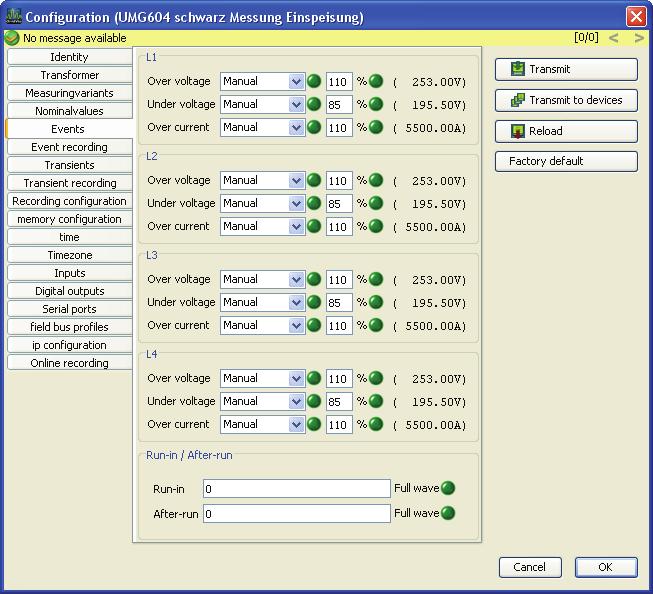
29 UMG604 Nominal Value The rated frequency applies to all 4 measurement channels. Select a network frequency according the existing network conditions. The nominal value is used as a reference to detect events (over/undervoltage and overcurrent). The nominal current of the transformer during feeding is required to calculate the K factor. 23
30 GridVis-Hilfe Event An event occurs when a set limit for current or voltage is violated. An event has an average, a minimum value and/or a maximum value, a start time and an end time. An event begins when a limit violation for a programmable number (pretrigger) of full-waves exists continuously. An event ends when no limit violations for a programmable number (post-trigger) of full-waves exists continuously.. Limits are programmed per measurement channel for overvoltage, undervoltage and overcurrent. Limits are set in percentages of Nominal Value. Adjustment range: Pre-trigger full-waves Adjustment range: Post-trigger full-waves You can turn off the limit monitoring (off/manual). If an event occurs, additional information can be saved in an Event Log. 24
31 UMG604 25

32 GridVis-Hilfe Event recording If an Event occurs, additional information can be saved in an event log. The full-wave absolute values of current and voltage measured values are recorded in an event log. You can select between the following forms of information to be recorded in the event log: -Only the measured values from the measurement input with the event. -Only the voltage and current values from the phase in which the event occurred. -All measured values from the other current measurement inputs and/or all measured values from the other voltage measurement inputs. - All measured values from all current and voltage measurement inputs. The event log begins when an event occurs. The length of the event log is determined by the number of full-wave absolute values up to the beginning of the event designated here with pretrigger and by the number of full-wave absolute values after the beginning of the event designated here with post-trigger. Adjustment range: Pre-trigger full-waves Adjustment range: Post-trigger full-waves 26
33 UMG604 Transients Transients are quick changes in voltage. The UMG604 detects transients that are longer than 50 us. You can only monitor the four voltage measurement inputs for transients. There are two independent criteria available to detect transients. Absolute: If a sampled value exceeds the program limit, a transient will be detected. Off: Turns off transient monitoring. Automatic: The limit will be calculated automatically and amounts to 110% of the current 200ms absolute value. Manual: The transient monitoring will use the programmed limit. Fast Increase: A transient will be detected if the difference between two neighboring sample points exceeds the programmed limit. Off: Turns off transient monitoring. Automatic:The limit will be calculated automatically and amounts to of the current 200ms absolute value. Manual: The transient monitoring will use the programmed limit. If a transient is detected, the limit will automatically be increased 20V in both Automatic and Manual mode. This automatic limit increase will subside within 10 minutes. If a transient is detected, the wave form will be saved in a Transient Log. If an additional transient is detected within the next 60 seconds, this transient will be logged with 512 points. 27

34 GridVis-Hilfe 28
35 UMG604 Transient recording If a Transient occurs, the wave form with a programmable number of sample points before and after the transient can be saved in a transient log. The interval between two sample points is always 50us. You can select between the following measurement channels to be recorded in the transient log: -Only the voltage measurement input will be recorded with the transient. -Only the voltage measurement input and accompanying current measurement input will be recorded with the transient. -All voltage measurement inputs will be recorded. -All voltage measurement inputs and current measurement inputs will be recorded. Log Length The number of sample points that should be recorded before the occurrence of the transient: Pre-trigger Adjustment range: points Post-trigger Adjustment range: points 29

36 GridVis-Hilfe 30

37 UMG604 Time The UMG604 has a battery buffered clock. The rate of error of the clock crystal will be harmonized with the room temperature during production so that the clock will only have a variation of +- 1 minute per month. If you would like to compare the logging of transients and events with the logs of other measuring sites, we recommend comparing and tracking the clock of the UMG604 with a time server. To do so the UMG604 will require the Ethernet interface (optional). The Network Time Protocol (NTP) will be used for the synchronization. Mode Off - The synchronization of the clock with the external time server is turned off. List - The UMG604 will wait for time information from a time server. Active - The UMG604 will request the time information. NTP Server - Enter the address of the time server here. 31
 for the display of the measured results with GridVis.")
38 GridVis-Hilfe Time Zone All time information for measured values, events and transients refers to UTC time (coordinated world time). The UTC time will be converted to central European time (CET) for the display of the measured results with GridVis. Central European time (CET) is the time zone which applies to central Europe and, among other countries, Germany. Standard Time - the time offset from central European standard time to UTC time is entered here. Daylight Savings Time - the time offset from central European daylight savings time to UTC time is entered here. Beginning of Daylight Savings Time - Enter the Beginning of Daylight Savings Time here. End of Daylight Savings Time - Enter the End of Daylight Savings Time here. 32

39 UMG604 Inputs The UMG604 has two digital inputs and a temperature measurement input. The two digital inputs can be used as digital inputs and as impulse counting inputs. Each impulse input can be assigned an impulse value. You can connect various temperature measurement sensors to the Temperature Measurement Input: PT100 - temperature range -55 C C PT temperature range -40 C C KTY83 - temperature range -99 C C KTY84 - temperature range -99 C C 33

40 GridVis-Hilfe Digital Outputs The UMG604 has two digital outputs. Each digital output can be programmed for event notifications or as an impulse output (S0 output). Each digital output can be programmed as an opener or a closer. If an output is programmed for event notification, one or more events can be assigned to it. If a selected event occurs, the event output will be activated. 34

41 UMG604 Serial Ports Device ID The device ID (device address) is required for the Modbus communication and for Profibus. RS485 You can choose between Modbus-Master or Modbus-Slave. You can choose between the following baud rates: 9600bps, 19200bps, 38400bps, 76800bps, bps and bps RS232 You can choose between Modbus-Master or Modbus-Slave. You can choose between the following baud rates: 9600bps, 19200bps, 38400bps and bps Profibus (Optional) Warning! Additional Profibus settings are made at Field Bus Profile. 35
. Measured values can be assigned to a Profibus profile with Edit.")
42 GridVis-Hilfe Field Bus Profile 16 different profiles can be configured for accessing the measured values in the UMG604 via Profibus (optional). Measured values can be assigned to a Profibus profile with Edit. 36

43 UMG604 Example of a Profibus profile 37

44 GridVis-Hilfe IP Configuration For devices with the Ethernet option, you must configure at least the IP Address and the Subnet Mask. With the UMG604, you can choose between the variants Used Default Setting, BootP anddhcp Mode. Used Default Setting All settings are applied by the user. BootP BootP allows the automatic incorporation of a UMG604 into an existing network. DHCP Mode The UMG604 obtains all settings from a DHCP server during startup. Warning! All configurations should only be made after checking with the Administrator. 38
45 UMG604 Serial Interfaces 39
46 GridVis-Hilfe Connection Diagrams PC - RS485 - UMG604 Connection The UMG604 has an RS485 interface and the PC has an RS232 interface. An interface converter is required. 40

47 UMG604 PC - Ethernet - UMG604 Connection The UMG604 and the PC have an Ethernet interface. You can make a direct connection between the PC and UMG604 with a "cross-over" patch cable. 41

48 GridVis-Hilfe PC - Ethernet (Switch) - UMG604 Connection The UMG604 has an Ethernet interface and the PC has an Ethernet interface. A switch or hub will be required. 42
49 UMG604 UMG96S in BACnet with the UMG604 as Gateway The UMG604 has an Ethernet interface and an RS485 interface. The UMG96S has an RS485 interface. The UMG604 is the Modbus-Master (RS485) and the UMG96S is the Modbus-Slave. The UMG96S is presented as a virtual device by UMG604 in BACnet. A Jasic program in the UMG604 will query the measured values in the connected UMG96S and provide them to BACnet. 43
50 GridVis-Hilfe UMG604 as Gateway Between GridVis and UMG96S The UMG604 has an Ethernet interface and an RS485 interface. The UMG96S has an RS485 interface. The UMG604 is the Modbus-Master (RS485) and the UMG96S is the Modbus-Slave. The baud rate of both devices must match. A Jasic program in the UMG604 will query the measured values in the connected UMG96S and provide them for further processing. 44
51 UMG604 Ethernet General Ethernet The UMG604 requires an Ethernet address to be able to operate in the Ethernet. The UMG6-4 offers three options: Fixed IP Address BootP DHCP Mode 1. Fixed IP Address The network address must be entered directly into the UMG604 for networks without a DHCP server. 2. BootP BootP allows the automatic incorporation of a UMG604 into an existing network. BootP is an older protocol and does not have the range of functions of DHCP. 3. DHCP Mode DHCP allows the automatic incorporation of a UMG604 into an existing network without additional configuration. The UMG604 automatically obtains the IP address, network mask and gateway via the DHCP server upon startup. You can program the corresponding setting under parameter address 205 in the UMG = Fixed IP 1 = BootP 2 = DHCP 45
52 GridVis-Hilfe UMG604 Fixed IP Address The network address must be entered directly into the UMG604 for networks without a DHCP server. You must make the following settings on the UMG604: 1. Set the UMG604 to a fixed IP. 2. Configure the desired IP address, IP mask and IP gateway. Address 300 = xxx (IP Address) 301 = --- xxx (IP Address) 302 = xxx --- (IP Address) 303 = xxx (IP Address) 304 = xxx (IP Mask) 305 = --- xxx (IP Mask) 306 = xxx --- (IP Mask) 307 = xxx (IP Mask) 310 = xxx (IP Gateway) 311 = --- xxx (IP Gateway) 312 = xxx --- (IP Gateway) 313 = xxx (IP Gateway) 46

53 UMG604 Settings of GridVis Add UMG604 You can connect the UMG604 to a PC via the Ethernet interface (optional), the RS485 interface or the RS232 interface. PCs without suitable interfaces will require an interface converter. See Connection Example. 1. Select UMG604 as the device type. 2. Select the connection type. The Connection Type (protocol) must be appropriate for the interface in the device. See selection table. UMG604 - Selection Table for the Connection Type (Protocol) UMG604 Interface TCP/IP Modbus RTU (RS485) Modbus via Ethernet Modbus/TCP Modbus 47
54 GridVis-Hilfe Ethernet (Optional) x x RS485 - x - - RS x x 48
, you will require a normal patch cable.")
55 UMG604 Connection type - TCP/IP You want to establish a connection between the UMG604 and the PC with GridVis. The UMG604 must have an Ethernet interface. For a direct between the UMG604 and the PC you will need a "crossover' patch cable. For connection via an existing network (hub/switch), you will require a normal patch cable. The address for the UMG604 can be obtained from a server via DHCP or you can directly enter a fixed address in the UMG604. The address can be entered in GridVis in numeric form or as a name. Timeout allows you to limit the number of connection attempts if no connection can be made. 49
 to RS232 (PC). For Interface configure the RS232 interface (e.g. COM1) on the PC. Connect this interface (e.g.com1) to the interface converter.")
56 GridVis-Hilfe Connection Type - Modbus RTU (RS485) You want to establish a connection between the UMG604 and the PC with GridVis. The UMG604 must have an RS485 interface. You require an interface converter from RS485 (UMG604) to RS232 (PC). For Interface configure the RS232 interface (e.g. COM1) on the PC. Connect this interface (e.g.com1) to the interface converter. The baud rate is the speed at which the data is transferred between the PC, the interface converter and the UMG604. As multiple UMG604 devices can be connected to the interface converter, the device address on the UMG604 must be entered. If no connection to the UMG604 can be made, another attempt will be conducted after the specified Timeout. When attempting to read data from the UMG604, the number of connection attempts will be limited by the Maximum Number of Attempts. GridVis will always attempt to connect to the UMG604 for online measurements. 50
57 UMG604 Modbus Modbus Address List A list of the measured values available in the UMG604 with the accompanying addresses and format exists in PDF format on the GridVis CD/DVD. 51
58 GridVis-Hilfe Modbus Status Notifications, Exception Codes The Jasic programming language Modbus functions Write Modbus and Read Modbus provide status notifications. Status notifications can be written to a Log file. The log file of a Jasic program can be displayed in the accompanying programming window under the Log tab. List of the Modbus status notifications and their meanings: 0 There are no errors. -1 Call improperly configured A serious error has occurred. This should not occur in the graphic programming. -2 CRC Error -3 Device is not answering The device is not connected. The baud rate is not properly configured. -4 Device in Modbus-Slave Mode The RS485 interface of the UMG604 must be set to Modbus-Master for the Modbus functions Write Modbus and Read Modbus in the Jasic programming language. 1 ILLEGAL FUNCTION 52 The function code received in the query is not an allowable action for the slave. If a Poll Program Complete command was issued, this code indicates that no program function preceded it.
59 UMG604 2 ILLEGAL DATA ADDRESS The data address received in the query is not an allowable address for the slave. 3 ILLEGAL DATA VALUE A value contained in the query data field is not an allowable value for the slave. 4 SLAVE DEVICE FAILURE An unrecoverable error occurred while the slave was attempting to perform the requested action. 5 ACKNOWLEDGE The slave has accepted the request and is processing it, but a long duration of time will be required to do so. This response is returned to prevent a timeout error from occurring in the master. The master can next issue a Poll Program Complete message to determine if processing is completed. 6 SLAVE DEVICE BUSY The slave is engaged in processing a long duration program command. The master should retransmit the message later when the slave is free. 7 NEGATIVE ACKNOWLEDGE The slave cannot perform the program function received in the query. This code is returned for an unsuccessful programming request using function code 13 or 14 decimal. The master should request diagnostic or error information from the slave. 8 MEMORY PARITY ERROR 53
60 GridVis-Hilfe The slave attempted to read extended memory, but detected a parity error in the memory. The master can retry the request, but service may be required on the slave device. 54
61 UMG604 Modbus Functions Modbus functions supported by the UMG604: 03 Read Holding Registers Reads the binary contents of holding registers (4X references) in the slave. 04 Read Input Registers Reads the binary contents of input registers (3X references) in the slave. 16 (10Hex) Preset Multiple Registers Presets values into a sequence of holding registers (4X references). When broadcast, the function presets the same register references in all attached slaves. 23 (17Hex) Read/Write 4X Registers Performs a combination of one read and one write operation in a single Modbus transaction. The function can write new contents to a group of 4XXXX registers, and then return the contents of another group of 4XXXX registers. Broadcast is not supported. Warning! The UMG604 does not support the function 06 Preset Single Register. 55
62 GridVis-Hilfe BACnet BACnet BACnet = Building Automation and Control Networks is a network protocol for building automation. BACnet ensures the interoperability between devices made by different manufacturers when all partners involved in a project agree upon certain BIBBs defined by the norm. A BIBB (BACnet Interoperability Building Block) defines which services and procedures must be supported on the server-side and the client-side in order to realize a certain requirement of the system. The UMG604 supports the device type B-SA with the BIBBs DS-RP-B and DS- WP-B. The BIBBs DS-WP-B, DS-WPM-B, AE-N-B and AE-N-B are also supported. A Jasic program forms the interface between the BACnet protocol in the UMG604 and external devices (GLT, UMG96s, third party devices, et cetera). BACnet is a fee-based software expansion and must be unlocked. BACnet can only be unlocked directly from the device. The unlock code consists of two 4 digit numbers which must be entered in the device at addresses 520 and 521. The user can adapt the interface (Jasic programs). Jasic programs can be accessed and modified by the user. Basic programming knowledge is required to modify or write Jasic programs. BACnet knowledge is required to adapt the interface to BACnet using a Jasic program. Janitza electronics GmbH has the BACnet Vendor Identification Number:
. Measured values are assigned to the corresponding object with a Jasic program.")
63 UMG604 UMG604 in BACnet One PC and two UMG604s are connected to an Ethernet network. Two UMG103s are connected to a UMG604 via the RS485 interface. One UM604 can manage a maximum of 90 objects. One UMG604 can manage a maximum of 40 objects per connected device (e.g. UMG103). Measured values are assigned to the corresponding object with a Jasic program. A maximum of 32 virtual devices, each with 40 objects, can be managed by a UMG604. A measured value in the UMG604 corresponds to the "analog input" in BACnet. All other floating values corresponds to the "analog values" in BACnet. Illustration: Example for operating 2 UMG604s and 2 UMG103s in BACnet. 57
64 GridVis-Hilfe BACnet Jasic Example Program example (Jasic program) for data transfer from the UMG604 to BACnet. 58
65 UMG604 59
66 GridVis-Hilfe Security Password System Password The system password is required to administrate the devices. The system password allows the calibration values, serial numbers and MAC addresses of the devices to be changed. The users do not require the system password. The system password is not given to the users for security reasons. FTP Password Allows access to all of the device values listed in the Modbus Addresses List. Allows access to all Jasic programs on the device. Allows the device homepage to be updated. The default FTP password is Janitza. Homepage Password The homepage password (Modbus address 502) allows the device homepage to be administrated. The homepage password allows Jasic programs to be loaded and started on the device homepage. Password Mode (Modbus Address 502). The UMG604 has three different password modes for the homepage password: 0 - The homepage password will not be asked for. (Default Setting) 2 - Changes to the configuration and displaying measured values require the password to be entered once Every change to the configuration requires the password to be entered. The default homepage password setting is 0. The homepage password is 4 characters. The homepage password is asked for when the homepage is opened. The homepage password will be asked for again after 5 minutes of inactivity. Display Password In order to make unintentional changes to the programming data directly on the device more difficult, you can configure a 4 character display password (Modbus Address 500) on the UMG604. The default setting is for no display password to be asked for. If you lose a modified display password, you can only delete the password via GridVis with the FTP password. 60
67 UMG604 The display password is 4 characters. You can enter the display password directly into the UMG604. Warning! The communication between GridVis and the devices is unencrypted up to GridVis version 1.1. Beginning with GridVis version 1.2, you can choose whether the communication between GridVis and the devices should be encrypted. The FTP password, homepage password and display password can only be changed by the user with GridVis beginning with GridVis version 1.2. GridVis and FTP Programs The FTP password is required. The FTP password is required for file transfer between GridVis and the devices via Modbus-TCP. The FTP password is required for file transfer between GridVis and the devices via Modbus-RTU over Ethernet. Modbus-TCP, Modbus-RTU No password protection is possible to the retrieval of measured values (Modbus Address Lists via the Modbus-RTU protocol. The FTP password is required for file transfer between GridVis and the devices via Modbus-TCP. The FTP password is required for file transfer between GridVis and the devices via Modbus-RTU over Ethernet. Profibus Profibus does not require a password. 61
68 GridVis-Hilfe Encryption Files can be transferred encrypted between GridVis and the UMG604. Files can be AES encrypted. AES stands for advanced encryption standard. AES is a symmetric encryption technique. 62
69 UMG604 Egg An Egg is a software expansion which can be loaded from GridVis onto a device, e.g. the UMG604. The software expansion can include a Jasic program and an HTML file (homepage expansion). Typical examples of software expansions are the Eggs for EMAX, Power Factor Controller and cost center determination. 63
70 GridVis-Hilfe EMAX The EMAX function serves to maintain a given power average in terms of the electrical energy within a certain measuring time. The EMAX function is a fee-based software expansion and must be unlocked on the UMG604 and requires the installation of an Egg with GridVis. To unlock the EMAX function, an unlock code consisting of two 4 character codes must be entered in the device at addresses 510 and 511. The Egg of the EMAX function consists of a Jasic inline code and a homepage expansion. The selection of the power values for the EMAX calculations and the assignment of the inputs and outputs is done by a Jasic program. The display of the EMAX measured values takes place on the UMG604 homepage. The entry of target values, the measurement period duration and the consumer properties can be done on the UMG604 homepage. 64
71 UMG604 Cost Center Determination The cost center determination function provides you with a quick overview of your energy use and the associated costs. The cost center determination is an approximate program. No guarantee is made. The cost center determination function is not fee-based and does not need to be unlocked. You can install the cost center determination function as an Egg with GridVis. You can load the Egg for the cost center determination function from the data carrier provided in the delivery. 65
72 GridVis-Hilfe Power Factor Controller The power factor controller functions serves together with other external components, like capacitor switching contactors and power capacitors to maintain a proscribed target CosPhi. The power factor controller function is a fee-based software expansion and must be unlocked on the UMG604 and requires the installation of an Egg with GridVis. To unlock the reactive power regulator function, an unlock code consisting of two 4 character codes must be entered in the device at addresses 510 and 511. The Egg of the power factor controller function consists of a Jasic inline code and a homepage expansion. The selection of the measured values for the power factor controller function and the assignment of the inputs and outputs is done by a Jasic program. The power factor controller function can be used in four instances. Each power factor controller function can switch up to 16 outputs. An output can be switched a maximum of 5 times per second. The display of the switching actions and the measured values takes place on the UMG604 homepage. The specification of the target CosPhi, the discharge times of the capacitors, the power capacitors, et cetera can be conducted via the UMG604 homepage. With the power factor controller function you can also: Compensate for individual phases, Compensate for "cross" loaded networks, so that all phases come closer to theactual CosPhi. 66
73 UMG604 Measured Value A measured value (in the UMG604) is an absolute value formed over a period (measurement window) of 200 ms. A measurement window in the 50Hz network consists of 10 periods and of 12 periods in the 60Hz network. A measurement window has a start time and an end time. The resolution of the start time and end time amount to approximately 2ns. The exactitude of the start time and end time are dependent upon the accuracy of the internal clock. (Typical +- 1 minute/month) To improve the accuracy of the internal clock, we recommended comparing and tracking the device clock with a time server. (Please see Time) See also Full Wave Absolute Value. 67
74 GridVis-Hilfe Full Wave Absolute Value A full wave absolute value is a measured value which is formed over measurement period which corresponds to a full wave. The measurement time amounts to 20 ms in a 50Hz network and to approximately 16.7 ms in a 60Hz network. The UMG604 calculates the following full wave absolute values for all phases: Voltage Current Active Power Fundamental Wave-Reactive Power Compensation (This measured value has a measurement error due to a constant phase shift of 1.5 and a ripple of 0.1% to 0.2% ) Measuring Time: 20ms at 50Hz, 16.7ms at 60Hz Processing Time: Typical 5ms, Maximum 10ms Variables for the Processing Time: Number of runtime of the Jasic programs, Homepage accesses Transfer Typical latency period 1 ms Maximum 7 ms See also Measured Value. 68
. The init.jas file does not contain any configuration data for the logs.")
75 UMG604 Init.jas The init.jas file is a text file located in the /sys/config/init.jas directory of the UMG604. The init.jas file contains the configuration data for the UMG604. A section of the init.jas is described by GridVis. The init.jas file does not contain any configuration data for the EMAX program (optional). The init.jas file does not contain any configuration data for the logs. 69
76 GridVis-Hilfe Ports Used by the UMG604 Devices with theethernet can use the following ports: UDP TFTP 1201 Modbus/TCP 502 DHCP 68 NTP 123 BaCnet Nameservice 1200 TCP HTTP 80 (can be modified in ini.jas) FTP command port 21, (data ports 1024, 1025, 1026, 1027) Modbus/TCP 502 (4 Ports) Modbus RTU via Ethernet 8000 (1 Port) 70

77 UMG103 Binding To GridVis UMG103 Connection PC - UMG103 Connection Example 1: The UMG103 has an RS485 interface and the PC has an RS232 interface. An interface converter is required. Example 2: The UMG103 has an RS485 interface and the PC has an Ethernet interface. A gateway is required. The UMG604, UMG507 and UMG510 can all be used as a gateway. 71
78 GridVis-Hilfe 72

79 UMG103 Configuration Identity The Name is displayed in the device list. You can add additional information about the device in Description. 73

80 GridVis-Hilfe Transformer Voltage Converter The voltage measurements inputs are designed for measurements in low voltages in which rated voltages (L-N/PE) up to 300V against ground can occur. A voltage converter is required for voltage measurements in grids with higher rated voltages. You must enter the phase voltage L-L for the primary voltage. Configure the converter properties for the voltage measurement inputs. Current Converter Currents up to 5A can be directly measured. Please consult the installation instructions for more information. A current converter is used for measurements of currents larger than 5A. Configure the converter properties for the current measurement input. 74

81 UMG103 Nominal Value The rated frequency applies to all 3 measurement channels. Select a network frequency according the existing network conditions. 75

82 GridVis-Hilfe Averaging Times The exponential averaging method used obtains at least 95% of the measured value after the configured averaging time. An averaging time of 15 minutes is set by default. 76
83 UMG103 Comparator/Limit 2 comparator groups each with 3 comparators (A, B, C) are available to monitor limits. The results of the comparator can be AND or OR connected and the result can also be inverted. The entire logic operation result of comparator group 1 can be assigned to Digital Output 1 and the entire logic operation result of comparator group 2 can be assigned to Digital Output 2. 77
84 GridVis-Hilfe Serial Ports You want to establish a Connection between the UMG 103 and the PC with GridVis. The UMG103 has an RS485 interface. The UMG103 can only function as Modbus-Slave. You require an interface converter from RS485 (UMG604) to RS232 (PC). For Interface configure the RS232 interface (e.g. COM1) on the PC. Connect this interface (e.g.com1) to the interface converter. The baud rate is the speed at which the data is transferred between the PC, the interface converter and the UMG604. You can change the baud rate after establishing a connection to the UMG103. If you select a fixed baud rate in the UMG103, you also have to set this baud rate in the counterpart station (PC, UMG604). The UMG103 will conduct a maximum of 8 attempts to determine the baud rate in the counterpart station with the Autodetect setting Baud Baud Baud Baud Autodetect (turned on by default) As multiple UMG103 devices can be connected to one interface converter, a device address must be entered for each UMG103. Allowed device addresses: Device address 0 is only intended for servicing purposes. 78

85 UMG103 79
86 GridVis-Hilfe Modbus Modbus Functions Modbus functions supported by the UMG103: 03 Read Holding Registers 04 Read Input Registers 06 Preset Single Register 16 Preset Multiple Registers 80
87 UMG96S Binding To GridVis UMG96S Connection PC - UMG96S Connection Example 1: The UMG96S has an RS485 interface and the PC has an RS232 interface. An interface converter is required. Example 2: The UMG96S has an M-bus interface and the PC has an RS232 interface. An interface converter is required. 81
88 GridVis-Hilfe Example 3: The UMG96S has an RS485 interface and the PC has an Ethernet interface. A gateway is required. The UMG604, UMG507 and UMG510 can all be used as a gateway. 82


89 UMG96S Add UMG96S The UMG96S must be connected with the PC via a gateway (device type). See Connection Example. You can choose from different connection types (protocols) based upon the gateway used (device type). 1. Select UMG96S as the device type. 2. Select the connection type. UMG96S - Selection overview for the connection type Device Modbus Modbus over Ethernet type/gateway RTU Modbus/TCP Modbus M-Bus 83
90 GridVis-Hilfe (RS485) UMG604 - x x - UMG x - UMG510 - x - - Interface converter x RS232/RS485 Interface converter RS232/M-Bus x 84

91 UMG96S Connection Type - Modbus-TCP Data transfer to Modbus TCP is similar to Modbus RTU except that TCP/IP packets are used. TCP port 502 is reserved for Modbus TCP. You want to configure and read a UMG96S with GridVis. You want to connect a UMG96S to a PC via Ethernet. You cannot directly connect the UMG96S via Ethernet because the UMG96S has an RS485 interface. You require a gateway. The UMG96S must have an RS485 interface. The gateway must have an RS485 interface and an Ethernet interface. A UMG604 with the corresponding options can also be used as a gateway. As multiple UMG96S devices can be connected to a gateway, the device address on the UMG96S must be entered. If no connection to the UMG96S can be made, another attempt will be conducted after the specified Timeout. When attempting to read data from the UMG96S, the number of connection attempts will be limited by Maximum Number of Attempts. GridVis will always attempt to connect to the UMG96S for online measurements. Modbus via Ethernet Ethernet address of the gateway Device address of the connected UMG96S In this example device address = 1 85

92 GridVis-Hilfe Connection Type - Modbus-RTU over Ethernet You want to configure and read a UMG96S with GridVis. You want to connect a UMG96S to a PC via Ethernet. You cannot directly connect the UMG96S via Ethernet because the UMG96S has an RS485 interface. You require a gateway. The UMG96S must have an RS485 interface. The gateway must have an RS485 interface and an Ethernet interface. A UMG604 with the corresponding options can also be used as a gateway. As multiple UMG96S devices can be connected to a gateway, the device address on the UMG96S must be entered. If no connection to the UMG96S can be made, another attempt will be conducted after the specified Timeout. When attempting to read data from the UMG96S, the number of connection attempts will be limited by Maximum Number of Attempts. GridVis will always attempt to connect to the UMG96S for online measurements. Ethernet address of the gateway Device address of the connected UMG96S In this example device address = 1 86

93 UMG96S Connection Type - Modbus RTU (RS485) You want to configure and read a UMG96S with GridVis. You want to connect the UMG96S to the RS232 interface of the PC. You cannot directly connect the UMG96S via Ethernet because the UMG96S has an RS485 interface. The UMG96S must have an RS485 interface. You require an interface converter from RS485 (UMG96S) to RS232 (PC). For Interface configure the RS232 interface (e.g. COM1) on the PC. Connect this interface (e.g.com1) to the interface converter. The baud rate is the speed at which the data is transferred between the PC, the interface converter and the UMG96S. As multiple UMG96S devices can be connected to the interface converter, the device address on the UMG96S must be entered. If no connection to the UMG96S can be made, another attempt will be conducted after the specified Timeout. When attempting to read data from the UMG96S, the number of connection attempts will be limited by Maximum Number of Attempts. GridVis will always attempt to connect to the UMG96S for online measurements. 87

94 GridVis-Hilfe Configuration Identity The Name is displayed in the device list. You can add additional information about the device in Description. 88

95 UMG96S Transformer Voltage Converter The voltage measurements inputs are designed for measurements in low voltages in which rated voltages (L-N/PE) up to 300V against ground can occur. A voltage converter is required for voltage measurements in grids with higher rated voltages. You must enter the phase voltage L-L for the primary voltage. Configure the converter properties for the voltage measurement inputs. Current Converter Currents up to 5A can be directly measured. Please consult the installation instructions for more information. A current converter is used for measurements of currents larger than 5A. Configure the converter properties for the current measurement input. 89
96 GridVis-Hilfe Nominal Value The rated frequency applies to all 3 measurement channels. Select a network frequency according the existing network conditions. 90

97 UMG96S Averaging Times The exponential averaging method used obtains at least 95% of the measured value after the configured averaging time. An averaging time of 15 minutes is set by default. 91
 can also record the averages for the current, voltage and power. The Averaging Timesfor current, voltage and power can be configured.")
98 GridVis-Hilfe Recording Configuration The UMG96S saves the configuration data, minimum and maximum values and measured values for the active power and the inductive reactive power in the EEPROM memory. Devices with flash memory (optional) can also record the averages for the current, voltage and power. The Averaging Timesfor current, voltage and power can be configured. The recording intervals correspond to the Averaging Times for the measured values of the current, voltage and power. All averages include the time of saving in UTC time as additional information. The real power and inductive reactive power can be saved every 60 minutes. A Limit Incident will be recorded when it occurs. If you allow Limit Incidents to be recorded, the maximum save time cannot be calculated. 92

99 UMG96S Time The UMG96S can be delivered with a battery buffered clock (optional). The clock is pre-programmed to the local time during manufacturing. The clock can be tracked during configuration by acquiring the UTC time from the connected PC. 93
100 GridVis-Hilfe Inputs/Outputs The UMG96S has two configurable connections. Different configurations of the connections are possible. Connection terminal 11/12 Impulse Output Reductive Power - Impulse Output for the Applied Active Power Comparator 1 - Output Comparator 1 Analog Output 1 - Output 1 as Analog Output (Optional) Profibus Remote Out 1 - Profibus Output 1 (Optional) HT/NT Real Power Switch - High tariff/low tariff switching for the real power. HT/NT Reactive Power Switch - High tariff/low tariff switching for the reactive power. HT/NT Real and Reactive Power Switch - High tariff/low tariff switching for the real power and the reactive power. Connection terminal 11/13 Impulse Output Reductive Power - Impulse Output for the Inductive Reactive Power Comparator 2 - Output Comparator 2 Analog Output 2 - Output 2 as Analog Output (Optional) Profibus Remote Out 2 - Profibus Output 2 (Optional) HT/NT Real Power Switch - High tariff/low tariff switching for the real power. HT/NT Reactive Power Switch - High tariff/low tariff switching for the reactive power. HT/NT Real and Reactive Power Switch - High tariff/low tariff switching for the real power and the reactive power. If a connection is used as an impulse output, the impulse value (Wh/Impulse) can the minimum impulse width can be programmed. 94

101 UMG96S 95
")
102 GridVis-Hilfe Analog Outputs (Optional) 96
103 UMG96S Comparator/Limit 2 comparator groups each with 3 comparators (A, B, C) are available to monitor limits. The results of the comparator can be AND or OR connected and the result can also be inverted. The entire logic operation result of comparator group 1 can be assigned to Digital Output 1 and the entire logic operation result of comparator group 2 can be assigned to Digital Output 2. 97

104 GridVis-Hilfe 98

105 UMG96S Display Configuration The UMG96S displays the first table of measured values from the current display profile after power has been restored. In order to keep the selection clear, only a portion of the available measured values have been pre-programmed to be retrieved in the measured value display. If other measured values are desired for the UMG96S display, you can select a different display profile. 3 default display profiles and one customer-specific display profile are available. -Profile 1, default -Profile 2, default -Profile 3, default - User defined, customer-specific 99
106 GridVis-Hilfe Modbus Modbus Functions Modbus functions supported by the UMG96S: 03 Read Holding Registers 06 Preset Single Register 16 Preset Multiple Registers 100
107 UMG507 Modbus Modbus Functions Modbus functions supported by the UMG507 on the RS485 interface: 03 Read Holding Registers 04 Read Input Registers 16 Preset Multiple Registers Modbus functions supported by the UMG507 on the RS232 interface: 03 Read Holding Registers 16 Preset Multiple Registers Warning! The UMG507 does not support the function 06 Preset Single Register. 101
108 GridVis-Hilfe Read Data New files will be created in the UMG507 measured values in the UMG507 are read. The UMG507 can manage a maximum of 800 files. The oldest file will be deleted if an attempt is made to store a larger number of files. 102
109 FAQ A Measured Value is Only Partially Displayed in the Online Graph This problem can occur when at least two measured values from different devices are displayed on the online graph. This can occur because the measured values are provided from devices with different chronological resolutions. The number of measured values per time unit that are to be displayed in the graph are of different sizes. The default setting for the presentation of the X axis in the graph is set to 2,000 points (measured value). The X axis presents the time in the graph. If a device, for example an UMG96S, only delivers two values per second, values for 1,000 seconds will be displayed in the X axis. If a value with 5 measured values per second from the UMG604 is then added to the graph, only 400 seconds (2000=400*5) of the values can be displayed in the graph. 103

110 GridVis-Hilfe Separate Measured Value Window Graphs are integrated with the GridVis program interface. If a graph is to be individual copied or moved to a second monitor, the graph must be separated from GridVis via the "Separate View/Window" command. 104
111 FAQ Read Measured Values from Recordings The UMG604 saves fixed measured values under fixed addresses (Modbus Address List) in the firmware. Recordings can also be configured for the UMG604 with the GridVis. Multiple measured values with the same averaging time can be collected in recordings. the evaluation and display of recordings generally takes place with the GridVis. You can use a Jasic program to make the measured values from recordings available for other applications. Example for reading measured values from recordings. 105

112 GridVis-Hilfe 106
Multitouch/BACnet Functional description UMG 604 / UMG 605 / UMG 508 / UMG 511
 Functional description Multitouch/BACnet UMG 604 / UMG 605 / UMG 508 / UMG 511 Doc no. 2.033.107.0 www.janitza.com BACnet activation UMG 604, Article no.: 52.16.081 BACnet activation UMG 605, Article no.:
Secure TCP/IP connection Description for UMG 604, UMG 605, UMG 508, UMG 509, UMG 511 and UMG 512
 Description Secure TCP/IP connection for UMG 604, UMG 605, UMG 508, UMG 509, UMG 511 and UMG 512 Doc. No. 2.047.014.1 / V 0.5-15.08.2016 www.janitza.com Janitza electronics GmbH Vor dem Polstück 1 D-35633
App Tariff Switch Functional description
 Functional description App Tariff Switch Dok. Nr. 2.033.111.2 www.janitza.com Janitza electronics GmbH Vor dem Polstück 1 D-35633 Lahnau Support tel. (0 64 41) 9642-22 Fax (0 64 41) 9642-30 e-mail: info@janitza.com
UMG 605. UMG 605 power quality analyzer (EN 50160, IEEE 519, ITIC)
") UMG 605 UMG 605 power quality analyzer (EN 50160, IEEE 519, ITIC) The UMG 605 power quality analyzer is particularly suitable for monitoring power quality according to standards such as EN 50160. All power
UMG 605 UMG 605 power quality analyzer (EN 50160, IEEE 519, ITIC) The UMG 605 power quality analyzer is particularly suitable for monitoring power quality according to standards such as EN 50160. All power
BACnet UMG96RM-E Functional description
 Functional description BACnet UMG96RM-E Doc. no. 2.040.095.1 www.janitza.com Janitza electronics GmbH Vor dem Polstück 1 D-35633 Lahnau Support tel. +49 (0) 64 41 9642-22 Fax +49 (0) 64 41 9642-30 e-mail:
UMG 605. UMG 605 Power quality analysers for DIN rails. Flicker. Reporting. Memory 128 MByte.
 Harmonics Alarm management Flicker Reporting Email Memory 128 MByte Power quality analysers for DIN rails Communication Profibus (DP / V0) Modbus (RTU, UDP, TCP, Gateway) TCP/IP BACnet (optional) HTTP
PQM - Power Quality Monitoring
 UMG 511 PQM - Power Quality Monitoring Class A power quality analyser according to IEC61000-4-30 The UMG 511 power quality analyser is particularly suitable for monitoring power quality according to standards
UMG 511. Class A EN UMG 511 Class A power quality analyzer. according to EN50160, IEEE 519, ITIC, IEC Areas of application
 UMG 511 Class A EN 50160 UMG 511 Class A power quality analyzer according to EN50160, IEEE 519, ITIC, IEC 61000-4-30 The UMG 511 power quality analyzer is particularly suitable for monitoring power quality
UMG 604. UMG 604 Power analyser. Modbus master, Ethernet gateway. Harmonics. Memory 128 MByte. Homepage. Graphic programming.
 Harmonics Modbus master, Ethernet gateway Memory 128 MByte Homepage Events Graphic programming UMG 604 Power analyser Communication Profibus (DP/ V0) Modbus (RTU, UDP, TCP, Gateway) TCP/IP BACnet (optional)
UMG 20CM. UMG 20CM 20 Channel Branch Circuit Monitoring Device with RCM. Harmonics via analysis channel RCM. Alarm management.
 RCM Harmonics via analysis channel Alarm management GridVis Analysis software 20 current channels 20 Channel Branch Circuit Monitoring Device with RCM Interfaces / communication RS485 RTU Accuracy of measurement
Smart Energy & Power Quality Solutions. ProData datalogger. Datalogger and Gateway
 Smart Energy & Power Quality Solutions ProData datalogger Datalogger and Gateway Smart and compact: Our most universal datalogger ever saves power costs Ethernet connection Modbus-Ethernet-Gateway 32 MB
FOUR FUNCTIONS ONE SOLUTION
 4-IN-1 FOUR FUNCTIONS ONE SOLUTION MID ENERGY MEASUREMENT DEVICE 4-in-1: Energy management, MID, power quality monitoring and RCM monitoring Intuitive user guidance High quality colour graphics display
PQM - Power Quality Monitoring
 UMG 604 PQM - Power Quality Monitoring High performance power analysers for DIN rails High performance power analysers from the UMG 604 product family are suitable for use at all network levels. The high
Synchronisation as per DCF-77 Functional description
 Functional description Synchronisation as per DCF-77 Doc. No. 2.033.109.0 www.janitza.com Janitza electronics GmbH Vor dem Polstück 1 D-35633 Lahnau Support tel. 0049 6441 9642-22 Fax 0049 6441 9642-30
ecoexplorer go Manual
 ecoexplorer go Manual Foreword Foreword Revision History Version Date Change 0.0 07/2016 First Edition 1.0 09/2016 Chapter 4.1.3.6 correction 2.0 03/2017 Chapter 3.4.13 and 3.5.1 deleted 3.0 02/2018 Page
CAS IKS Gateway (Modbus RTU/TCP and HTML) Manual
 Manual") CAS-2700-42 IKS to Modbus RTU Gateway CAS 2700-42 IKS Gateway (Modbus RTU/TCP and HTML) Manual CAS 2700-42 IKS Gateway Manual Page 1 of 34 BLANK PAGE CAS 2700-42 IKS Gateway Manual Page 2 of 34 Contents
CAS-2700-42 IKS to Modbus RTU Gateway CAS 2700-42 IKS Gateway (Modbus RTU/TCP and HTML) Manual CAS 2700-42 IKS Gateway Manual Page 1 of 34 BLANK PAGE CAS 2700-42 IKS Gateway Manual Page 2 of 34 Contents
Document Name: User Manual for SC10MK, Modbus RTU to Modbus TCP Converter
 Document Name: User Manual for SC10MK, Modbus RTU to Modbus TCP Converter Login for the first time, please use http://192.168.1.100 To key in user name and password is for identifying authorization. Default
ETHM-2. Ethernet Module. SATEL sp. z o.o. ul. Schuberta Gdańsk POLAND tel
 Ethernet Module ETHM-2 Firmware version 1.0 ethm2_en 09/08 SATEL sp. z o.o. ul. Schuberta 79 80-172 Gdańsk POLAND tel. + 48 58 320 94 00 info@satel.pl www.satel.pl SATEL's goal is to continually improve
UMG 511. Class A power quality analyser. Reporting Homepage
 Class A power quality analyser Class A Flicker Reporting Homepage Harmonics Alarm management Communication Profibus (DP/V0) Modbus (RTU, TCP, Gateway) TCP/IP BACnet (optional) HTTP (configurable homepage)
Technical Documentation
 BLR-CM - MODBUS Technical Documentation BLR-CM MODBUS Beluk GmbH Tel.: +49/(0)8861/2332-0 Fax: +49/(0)8861/2332-22 e-mail: blr@beluk.de http://www.beluk.de BLR-CM - MODBUS Page 2 of 20 Document history
Motortronics VirtualSCADA VS2-MT Communication Gateway VS2-MT User Manual Revision
 Motortronics VirtualSCADA VS2-MT Communication Gateway VS2-MT User Manual Revision 1.03.00 Motortronics / Phasetronics 1600 Sunshine Drive Clearwater, Florida 33765 Tel: 727-573-1819 Fax: 727-573-1803
ETC II Modbus Communications Protocol Reference Guide
 ETC II Modbus Communications Protocol Reference Guide SATEC Ltd. BG0595 Rev. A1 Every effort has been made to ensure that the material herein is complete and accurate. However, the manufacturer is not
AP-ENBD User Manual V0.2
 AP-ENBD User Manual V0.2 2015/12 Catolog Catolog... 2 1 Introduction... 1 1.1 Communication Structure... 1 1.2 Internal Principle... 2 2 Installation... 2 2.1 Connect to the Same Router (or Switch )...
DNP 3.0 Serial (RS232/RS485) and Ethernet (TCP/IP) SCADA Interface for TPSD/A36D Chargers with S2A-205T Option 21P or 57T or 57U. Setup Instructions
 and Ethernet (TCP/IP) SCADA Interface for TPSD/A36D Chargers with S2A-205T Option 21P or 57T or 57U. Setup Instructions") La Marche Manufacturing Company www.lamarchemfg.com DNP 3.0 Serial (RS232/RS485) and Ethernet (TCP/IP) SCADA Interface for TPSD/A36D Chargers with S2A-205T Option 21P or 57T or 57U Setup Instructions This
La Marche Manufacturing Company www.lamarchemfg.com DNP 3.0 Serial (RS232/RS485) and Ethernet (TCP/IP) SCADA Interface for TPSD/A36D Chargers with S2A-205T Option 21P or 57T or 57U Setup Instructions This
Lufkin Modbus Serial Driver Help Kepware Technologies
 Lufkin Modbus Serial Driver Help 2012 Kepware Technologies 2 Table of Contents Table of Contents 2 3 Overview 3 Channel Setup 4 Device Setup 5 Cable Diagram 5 Modem Setup 6 Block Sizes 6 Framing 7 Error
ProData DATA LOGGER. Chapter 03 ProData data logger. Ethernet. Pulse inputs and Pulse outputs. Modbus-Ethernet gateway. Thermistor input.
 ProData DATA LOGGER Ethernet Pulse inputs and Pulse outputs Modbus-Ethernet gateway Thermistor input Memory 32 MB Threshold value monitoring 139 Smart and compact: Save energy costs through the universal
ProData data logger. Ethernet. Pulse inputs and Pulse outputs. Thermistor input. Modbus-Ethernet gateway. Memory 32 MB. Threshold value monitoring
 Ethernet Pulse inputs and Pulse outputs Modbus-Ethernet gateway Thermistor input Memory 32 MB Threshold value monitoring ProData data logger 1 Smart and compact: Save energy costs through the universal
CAS & CAS UL. Modbus RTU Data Client. (Hardware and Software Solutions) Manual
 Manual") CAS-2500-01 & CAS-2500-01-UL ModbusRTU Data Client (Hard and Soft Solutions) CAS 2500-01 & CAS 2500-01-UL Modbus RTU Data Client (Hardware and Software Solutions) Manual Email: dfs@chipkin.com Website:
CAS-2500-01 & CAS-2500-01-UL ModbusRTU Data Client (Hard and Soft Solutions) CAS 2500-01 & CAS 2500-01-UL Modbus RTU Data Client (Hardware and Software Solutions) Manual Email: dfs@chipkin.com Website:
UMG 20CM. 20 Channel Branch Circuit Monitoring Device with RCM
 20 Channel Branch Circuit Monitoring Device with RCM RCM Harmonics via analysis channel Alarm management GridVis Analysis software 20 current channels Interfaces / communication RS485 RTU Accuracy of measurement
6-Channel power analyser UMG 96RM-E. Operating current and RCM fault current monitoring. Smart Energy & Power Quality Solutions RCM.
 Smart Energy & Power Quality Solutions Memory 256 MB RCM Ethernet-Modbus-Gateway Alarm management Homepage BACnet (optional) Operating current and RCM fault current monitoring The with 6 current channels
INSTRUCTION MANUAL V1. 2x A
 INSTRUCTION MANUAL V1. 2x A INTRODUCTION... 3 CONNECTIONS AND INSTALLATION... 4 MECHANICAL INSTALLATION... 4 ATTACHING AND DETACHING THE FRONT COVER... 8 ATTACHING AND DETACHING THE HMI... 9 ELECTRICAL
Modbus RTU/TCP Installation and Programming Guide PC3400 Particle Counter
 Chemtrac, Inc. Modbus RTU/TCP Installation and Programming Guide PC3400 Particle Counter Chemtrac, Inc. rev. B111811 Introduction This guide is for use with Chemtrac s PC 3400 D Particle Counters. The
POWER SIMPLY SAVE. Catalogue Catalogue 2017
 Smart Energy & Power Quality Solutions Smart Energy & Power Quality Solutions Catalogue 2017 Catalogue 2017 Janitza electronics GmbH Vor dem Polstück 6 35633 Lahnau Deutschland Tel.: +49 6441 9642-0 Fax:
MODBUS APPLICATION MANUAL DKM-411
 MODBUS APPLICATION MANUAL DKM-411-1 - COPYRIGHT NOTICE Any unauthorized use or copying of the contents or any part of this document is prohibited. This applies in particular to trademarks, model denominations,
MODBUS APPLICATION MANUAL DFC-0124
 MODBUS APPLICATION MANUAL DFC-0124-1 - COPYRIGHT NOTICE Any unauthorized use or copying of the contents or any part of this document is prohibited. This applies in particular to trademarks, model denominations,
ETOR-4 Ethernet/Serial Gateway ETOR-4. Ethernet/Serial Gateway USER MANUAL
 ETOR-4 Ethernet/Serial Gateway USER MANUAL 1 TABLE OF CONTENTS SECTION 1 GENERAL INFORMATION...6 SECTION 2 INSTALLATION...9 2.1 Definitions on ETOR... 9 2.2 Configuring ETOR...10 2.3 Required Installations
INDUSTRIAL ETHERNET MODULE TBOX Manual
 INDUSTRIAL ETHERNET MODULE TBOX Manual XINJE ELEC. CO., LTD CONTECTS 1 INTRODUCTION...1 2 COM PORT AND DISPLAY......3 3 PARAMETER SETTING...8 1 INTRODUCTION 1. Brief introduction Modbus protocol is industrial
NOVUS AUTOMATION 1/92
 INSTRUCTION MANUAL V1.1x INTRODUCTION... 3 CONNECTIONS AND INSTALLATION... 4 MECHANICAL INSTALLATION... 4 ATTACHING AND DETACHING THE FRONT COVER... 8 ATTACHING AND DETACHING THE HMI... 9 ELECTRICAL CONNECTIONS...
DATA LOGGER MODELS DL-1080/1081
 DATA LOGGER MODELS DL-1080/1081 USER MANUAL V1.5x INTRODUCTION... 4 CONNECTIONS AND INSTALLATION... 5 MECHANICAL INSTALLATION... 5 ATTACHING AND DETACHING THE FRONT COVER... 8 ATTACHING AND DETACHING THE
Description (common to all MPC controllers)* Connection and communication functions 2 / 5
* Connection and communication functions 2 / 5") 1 / 5 Description (common to all MPC controllers)* Connection and communication Gateway Serial interfaces Routing Network TCP/IPSerial (Request) TCP/IPSerial (Transparent) TCP/IPModbus RTU (Address)
1 / 5 Description (common to all MPC controllers)* Connection and communication Gateway Serial interfaces Routing Network TCP/IPSerial (Request) TCP/IPSerial (Transparent) TCP/IPModbus RTU (Address)
Networks TN, TT, IT networks 3 and 4-phase networks Up to 4 single-phase networks
 Memory 256 MB 8 Tariffs Harmonics Pulse inputs and outputs Measurement accuracy 0.5 UMG 96RM Multifunction power analyser Communication (device-specific) Modbus (RTU) Profibus DP V0 Profinet TCP/IP M-Bus
DATA LOGGER MODELS DL-1080/1081
 DATA LOGGER MODELS DL-1080/1081 USER MANUAL V1.3x INTRODUCTION... 4 CONNECTIONS AND INSTALLATION... 5 MECHANICAL INSTALLATION... 5 ATTACHING AND DETACHING THE FRONT COVER... 8 ATTACHING AND DETACHING THE
ETOR-4. Ethernet/Serial Gateway USER MANUAL
 ETOR-4 Ethernet/Serial Gateway USER MANUAL 1 TABLE OF CONTENTS SECTION 1 GENERAL INFORMATION...6 SECTION 2 INSTALLATION...9 2.1 Definitions on ETOR... 9 2.2 Configuring ETOR...10 2.3 Required Installations
Modbus ASCII Serial Device Driver Help 2009 Kepware Technologies
 Modbus ASCII Serial Device Driver Help 2009 Kepware Technologies 1 Table of Contents 1 Getting Started... 3 Help Contents... 3 Overview... 3 2 Device Setup... 3 Device Setup... 3 Cable Diagram... 4 Modem
UMG 96RM. UMG 96RM Universal measurement instrument. Areas of application
 UMG 96RM UMG 96RM Universal measurement instrument The UMG 96RM is a very compact and powerful universal measurement device designed for use in low and medium voltage distribution systems. In addition
Embedded Modbus TCP Module GS11-MT. User Manual REV 1.1. SST Automation.
 Embedded Modbus TCP Module GS11-MT User Manual REV 1.1 SST Automation E-mail: SUPPORT@SSTCOMM.COM WWW.SSTCOMM.COM Catalog 1 About the Embedded Module... 4 1.1 General...4 1.2 Features... 4 1.3 Specifications...4
INSTRUCTION MANUAL. V1.6x F. CE Mark
 www.novusautomation.com/fieldlogger-en INSTRUCTION MANUAL V1.6x F CE Mark This is a Class A device. In a domestic environment, this device may cause radio interference in which case the user may be required
Softstarters. Type PSTX Fieldbus communication, Anybus Modbus TCP. 1SFC132087M0201 March SFC132087M0201 1
 Softstarters Type PSTX Fieldbus communication, Anybus Modbus TCP 1SFC132087M0201 March 2015 1SFC132087M0201 1 1 Modbus TCP The Modbus protocol is a fieldbus protocol that provides full control and status
Temperature-Humidity Sensor Configuration Tool Rev. A 1/25/
 Rev. A 1/25/213 172 Contents Contents Temperature-Humidity Sensor Configuration Tool... 3 Read Sensor Screen... 3 Manual Calibration Screen... 4 Register View Screen... 5 Modbus Registers... 6 Reprogram
Meter Connection Manual V Solar-Log
 EN Meter Connection Manual V.4.1.1 Solar-Log 1 Publisher: Solare Datensysteme GmbH Fuhrmannstr. 9 72351 Geislingen-Binsdorf Germany International support Tel.:+49 7428 9418-640 Fax:+49 7428 9418-280 e-mail:
Transienten. Datenspeicher
 25. Grenzwertüberwachung Class A RCM Residual current monitoring Transienten Reporting Alarm management Harmonics Voltage quality Spannungsqualität Datenspeicher 32 MB 128 MB 256 MB 512 K Certificated
NET101. RS232 / RS422 / RS485 to Ethernet Converter. User s Manual. Version 1.2
 NET101 RS232 / RS422 / RS485 to Ethernet Converter User s Manual Version 1.2 Copyright Information Copyright 2004-2005, Mega System Technologies, Inc. All rights reserved. Reproduction without permission
PQM - Power Quality Monitoring
 UMG 507 PQM - Power Quality Monitoring Continuous measurements and the Ethernet Power analysers of the UMG 507 product family are suitable for use at all network levels. The continuous measurement enables
INTAB FLEXIBLE SYSTEM MANUAL. INTAB INTERFACE-TEKNIK AB GJUTAREVÄGEN 1, STENKULLEN 0/103
 INTAB FLEXIBLE SYSTEM MANUAL INTAB INTERFACE-TEKNIK AB GJUTAREVÄGEN 1, 443 61 STENKULLEN www.intab.se 0/103 Intab Flexible System INSTRUCTION MANUAL V1.5x B INTRODUCTION... 3 CONNECTIONS AND INSTALLATION...
INSTRUCTION MANUAL ESI-Manager communication How to use RS485 USB Ethernet connections
 INSTRUCTION MANUAL ESI-Manager communication How to use RS485 USB Ethernet connections Table of contents 1 Introduction to this manual... 4 1.1 Intended audience... 4 1.2 Before you start... 4 1.3 How
USER MANUAL. Longo programmable controller LPC-2.MC8 Main module. Version 10
 USER MANUAL Longo programmable controller LPC-2.MC8 Main module Version 10 SMARTEH d.o.o. / Poljubinj 114 / 5220 Tolmin / Slovenia / Tel.: +386(0) 388 44 00 / e-mail: info@smarteh.si / www.smarteh.si Written
Modbus Protocol. for VASCO, VASCO Solar and MIDA devices. manmodbus_eng_00
 Protocol for VASCO, VASCO Solar and MIDA devices manmodbus_eng_00 Index 1. introduction... 3 2. on Nastec devices... 3 3. Transmission modes... 3 4. Connections... 3 5. Programming... 4 6. Index list...
BLR-CM Modbus. Technical Documentation. Technical Documentation. Rev BLR-CM Modbus. Beluk GmbH Taubenstrasse Schongau Germany
 Beluk GmbH Taubenstrasse 1 86956 Schongau Germany Tel.: +49/(0)8861/2332-0 Fax: +49/(0)8861/2332-22 E-Mail: blr@beluk.de Web: http://www.beluk.de Document history Date Name Revision Comment 08.11.06 ATh
DNP 3.0 Serial (RS232/RS485) and Ethernet (TCP/IP) SCADA Interface for A31 Inverters with S2A-383S Option 21P. Setup Instructions
 and Ethernet (TCP/IP) SCADA Interface for A31 Inverters with S2A-383S Option 21P. Setup Instructions") La Marche Manufacturing Company www.lamarchemfg.com DNP 3.0 Serial (RS232/RS485) and Ethernet (TCP/IP) SCADA Interface for A31 Inverters with S2A-383S Option 21P Setup Instructions This manual is valid
La Marche Manufacturing Company www.lamarchemfg.com DNP 3.0 Serial (RS232/RS485) and Ethernet (TCP/IP) SCADA Interface for A31 Inverters with S2A-383S Option 21P Setup Instructions This manual is valid
Modbus Remote Communication Protocol for REM 54_. Technical Description
 Modbus Remote Communication Protocol for REM 54_ 1MRS 750781-MUM Issued: 08.03.2002 Version: A/18.06.2002 Checked: ML Approved: AF Remote Communication Protocol for REM 54_ Modbus We reserve the right
STS Web card for Upsilon/Epsilon STS (66073) STS Web card User Manual
 STS Web card User Manual") STS Web card User Manual STS Web card for Upsilon/Epsilon STS (66073) STS Web card User Manual 34003765EN/BB Contents 1 PRESENTATION...3 1.1 OVERVIEW...3 1.2 USE IN A UPS...3 1.3 FUNCTIONS...4 1.4 TECHNICAL
STS Web card User Manual STS Web card for Upsilon/Epsilon STS (66073) STS Web card User Manual 34003765EN/BB Contents 1 PRESENTATION...3 1.1 OVERVIEW...3 1.2 USE IN A UPS...3 1.3 FUNCTIONS...4 1.4 TECHNICAL
A12B DNP 3.0 SERIAL & ETHERNET (TCP/IP) SCADA INTERFACE
 SCADA INTERFACE") A12B DNP 3.0 SERIAL & ETHERNET (TCP/IP) SCADA INTERFACE OPTION 21P INSTRUCTIONS This manual is only valid for A12B units equipped with a S2A-225C control module and a S2A-383S-3X20 communications card.
A12B DNP 3.0 SERIAL & ETHERNET (TCP/IP) SCADA INTERFACE OPTION 21P INSTRUCTIONS This manual is only valid for A12B units equipped with a S2A-225C control module and a S2A-383S-3X20 communications card.
Smart Energy & Power Quality Solutions. UMG 103-CBM energy meter with memory COMPACT, BEST-PRICED & SAFETY
 COMPACT, BEST-PRICED & SAFETY UMG 96 RM PN 2 Large measurement data memory for even more data security Qualified statements on energy consumption and power quality cannot be achieved with measurements
Modbus Unsolicited Serial Driver PTC Inc. All Rights Reserved.
 2018 PTC Inc. All Rights Reserved. 2 Table of Contents 1 Table of Contents 2 3 Overview 4 Setup 5 Channel Setup 5 Channel Properties 6 Channel Properties General 6 Channel Properties Serial Communications
Smart Energy & Power Quality Solutions. GridVis introduction. Dok. Nr.:
 GridVis introduction Dok. Nr.: 2.047.006.2 Contents Minimum requirements 4 Software versions - GridVis license model 5 Installation and Activation of the GridVis Desktop Software 6 Installation of the
User Manual Edition: v a
 WPC-832-Con 2 Ports Modbus TCP to Modbus RTU Wi-Fi, Ethernet connection Data Concentrator User Manual Edition: v.201809a http://www.tcpipweb.com Table of Contents Introduction------------------------------------------------------------------------------------------------------------------------------
INSTRUCTION MANUAL RVT communication How to use RS485 USB Ethernet RVT connections
 INSTRUCTION MANUAL RVT communication How to use RS85 USB Ethernet RVT connections Table of contents 1 Introduction to the controller... 1.1 Intended audience... 1.2 Before you start... 1.3 How to use this
RC-SV Configuration Guide (Rev 4)
") Kramer Electronics, Ltd. RC-SV Configuration Guide (Rev 4) Software Version 2.1.2.69 Intended for Kramer Technical Personnel or external System Integrators. To check that you have the latest version, go
Kramer Electronics, Ltd. RC-SV Configuration Guide (Rev 4) Software Version 2.1.2.69 Intended for Kramer Technical Personnel or external System Integrators. To check that you have the latest version, go
Ethernet to RS-232/485 Gateway
 Ethernet to RS-232/485 Gateway (Mode: IP-S) Feature: Operation voltage : DC 7V ~ 20V. RS232 Interface Meets or Exceeds TIA/EIA-232-F and ITU Recommendation V.28 Interface : ±12V levels compatibility. Data
Poseidon 4002 MANUAL
 Poseidon 4002 MANUAL Poseidon 4002 MANUAL POWER input 12VDC supply (jack or terminals) INPUTS Binary inputs 1 6 (for contacts) OUTPUTS Two 50V rated switchover relay contacts ETHERNET 10 or 100/10 Mbps
express yourself through light Based on Firmware 111
 express yourself through light BACnet TM Based on Firmware 111 1 of 10 CONTENTS BACNET TM SETUP 3 NETWORK TOPOLOGY 4 MINIMUM VERSION REQUIREMENTS 4 BACNET SETTINGS 4 CONFIGURE MAPPING 5 BACNET APPLICATION
Easy Config. Configuration tool for ATYS, COUNTIS and DIRIS INSTRUCTION MANUAL. easy-config_software
 INSTRUCTION MANUAL Easy Config Configuration tool for ATYS, COUNTIS and DIRIS EN www.socomec.com/ easy-config_software www.socomec.com EN CONTENTS 1. DOCUMENTATION...3 2. PRELIMINARY OPERATIONS...3 3.
NCOM SERIAL DEVICE SERVER 1XX SERIES USER S MANUAL
 NCOM SERIAL DEVICE SERVER 1XX SERIES USER S MANUAL 2017-07-07 Edition Titan Electronics Inc. Web: www.titan.tw Contents 1. INTRODUCTION... 4 1.1 Key Features... 5 1.2 Specifications... 6 2. PANEL LAYOUT
NB-GPC Family Protocol Implementation Conformance Statement (PICS)
") Vendor Name: American Auto-Matrix Product Name: NB-GPC Family Product Model Number: NB-GPC1, NB-GPC2, NB-GPC3, NB-GPC4 Firmware Revision: 2.00 BACnet Protocol Revision: 4 Product Description: NB-GPC controllers
Vendor Name: American Auto-Matrix Product Name: NB-GPC Family Product Model Number: NB-GPC1, NB-GPC2, NB-GPC3, NB-GPC4 Firmware Revision: 2.00 BACnet Protocol Revision: 4 Product Description: NB-GPC controllers
CREATING PANEL APPLICATIONS
 CREATING PANEL APPLICATIONS 3.1. Setting up the Panel Application... 1 3.1.1. General Settings...2 3.1.2. Custom Settings...5 3.1.3. Activating Multiple Overlapped Buttons by One Touch...7 3.1.4. Specifying
rbox610 Series Robust Din-rail Fanless Embedded System Web Configuration and App Software User s Manual
 rbox610 Series Robust Din-rail Fanless Embedded System Web Configuration and App Software User s Manual Disclaimers This manual has been carefully checked and believed to contain accurate information.
DATA LOGGER (Version V1.3)
") WYLER AG Im Hölderli CH-8405 WINTERTHUR Switzerland Tel. 0041 (0) 52 233 66 66 Fax. 0041 (0) 52 233 20 53 Homepage: http://www.wylerag.com E-Mail: wyler@wylerag.com Operating instructions DATA LOGGER (Version
WYLER AG Im Hölderli CH-8405 WINTERTHUR Switzerland Tel. 0041 (0) 52 233 66 66 Fax. 0041 (0) 52 233 20 53 Homepage: http://www.wylerag.com E-Mail: wyler@wylerag.com Operating instructions DATA LOGGER (Version
Industrial-Automation System HIMatrix. MODBUS Master/Slave. Manual
 Industrial-Automation System HIMatrix MODBUS Master/Slave Manual HIMA Paul Hildebrandt GmbH + Co KG Rev. 0.02 Industrial Automation HI 800 003 HEA Important Notes All HIMA products mentioned in this manual
FnIO S-Series. FnIO MODBUS Adapter Specification Rev 1.00 NA-9473 (MODBUS/RS485) Page 1 of 30. NA-9473 (MODBUS/RS485) Adapter
 Page 1 of 30. NA-9473 (MODBUS/RS485) Adapter") Rev 1.00 NA-9473 (MODBUS/RS485) Page 1 of 30 FnIO S-Series NA-9473 (MODBUS/RS485) Adapter Rev 1.00 NA-9473 (MODBUS/RS485) Page 2 of 30 DOCUMENT CHANGE SUMMARY REV. PAGES REMARKS DATE Editor Draf t#0 First
Rev 1.00 NA-9473 (MODBUS/RS485) Page 1 of 30 FnIO S-Series NA-9473 (MODBUS/RS485) Adapter Rev 1.00 NA-9473 (MODBUS/RS485) Page 2 of 30 DOCUMENT CHANGE SUMMARY REV. PAGES REMARKS DATE Editor Draf t#0 First
EGW1-IA3-MB User s Manual
 www.exemys.com Rev. 0 1 Products are in constant evolution to satisfy our customer needs. For that reason, the specifications and capabilities are subject to change without prior notice. Updated information
Model 2000 Programmer EnSonic Display & Control Unit. Document code: M2KCNF.001
 Model 2000 Programmer EnSonic Display & Control Unit Document code: 10735.M2KCNF.001 Document Model 2000 Programmer: EnSonic Display & Control Unit Document code 10735.M2KCNF.001 Date January 25, 2004
BACnet Protocol Implementation Conformance Statement Unitary Protocol Converter (UPC)
") Date: 10/05/2016 Vendor Name: OEMCtrl Product Name: Unitary Protocol Converter Product Model Number: UPC Applications Software Version: Firmware Revision: 6.00a BACnet Protocol
Date: 10/05/2016 Vendor Name: OEMCtrl Product Name: Unitary Protocol Converter Product Model Number: UPC Applications Software Version: Firmware Revision: 6.00a BACnet Protocol
Ethernet to Serial Port Module RS-232/422/485 to Internet Gateway
 Ethernet to Serial Port Module RS-232/422/485 to Internet Gateway (Model: IPM-S) Wireless Gateway: Active RFID Gateway Bluetooth to Internet Application: Energy Meter Networks Motor Control Industrial
S5 Communications. Rev. 1
 S5 Communications Rev. 1 Page 1 of 15 S5 Communications For a complete understanding of the S5 Battery Validation System (BVS) communication options, it is necessary to understand the measurements performed
Conto D1 MODBUS COMMUNICATION PROTOCOL
 ENERGY METER Conto D1 MODBUS COMMUNICATION PROTOCOL 4/03/15 Pagina 1 di 7 FIRMWARE CONTENTS 1.0 ABSTRACT 2.0 DATA MESSAGE DESCRIPTION 2.1 Parameters description 2.2 Data format 2.3 Description of CRC calculation
Host Controller Systems. Instruction Manual
 Host Controller Systems Instruction Manual Original Instructions 132114 Rev. I 30 July 2014 132114 Contents 1 Host Controller Systems... 3 2 SureCross DX80 Modbus Register Definitions... 4 2.1 Modbus Holding
System-10 BTU Meter BACnet Network Interface Installation Guide
 BACnet System-10 BTU Meter BACnet Network Interface Installation Guide 0652-3 1500 North Belcher Road, Clearwater, FL 33765 Tel (727) 447-6140 Fax (727) 442-5699 www.onicon.com sales@onicon.com 04-12 System-10-BAC
PROFINET, EtherNet/IP, Industrial Ethernet, Modbus TCP,
 Release Note TH LINK PROFINET, EtherNet/IP, Industrial Ethernet, Modbus TCP, PC Industrial Ethernet Version 4.1.0.0 Softing Industrial Automation GmbH Richard-Reitzner-Allee 6 85540 Haar Tel.: +49 89 4
BMS-Ethernet-Gateway COM460IP
 BMS-Ethernet-Gateway TDB501015en / 11.2012 BMS-Ethernet-Gateway BMS-Ethernet-Gateway Device features Modular, expandable gateway between BMS bus and TCP/IP Gateway between BMS bus and Ethernet Range of
Beijer Electronics has no obligation to supply the holder with updated versions.
 1 Function and area of use The Programmable I/O (PIO) combines CODESYS control with the opportunity to build control systems to the exact size and specifications for the I/O signals involved. In this document
Description of options. user s manual. DEIF A/S Frisenborgvej 33 DK-7800 Skive Tel.: Fax:
 Description of options TCP/IP Ethernet module user s manual DEIF A/S Frisenborgvej 33 DK-7800 Skive Tel.: +45 9614 9614 Fax: +45 9614 9615 info@deif.com www.deif.com Document no.: 4189320029B Legal information
TOP Server V5 to MicroLogix Using DNP3 Ethernet Driver
 TOP Server V5 to MicroLogix 1400 Using DNP3 Ethernet Driver Page 2 of 36 Table of Contents INTRODUCTION 3 CONFIGURING THE MICROLOGIX 1400 AS A DNP3 SLAVE 4 CONFIGURING TOP SERVER AS A DNP3 MASTER 9 TESTING
Modbus TCP + Ethernet EN
 Version 0.10 2015 dieentwickler Elektronik GmbH Linzer Straße 4, 4283 Bad Zell / AUSTRIA Telefon: +43 7263 20900-0, Telefax: +43 7263 20900-4 office@dieentwickler.at, www.dieentwickler.at Preface Table
Heatronic Introduction. BAS Integration Manual. Table of Contents
 Heatronic 4000 BAS Integration Manual Introduction The Heatronic 4000 can communicate with a Building Automation System (BAS) using either BACnet IP or Modbus. This manual provides information about boiler
ETC One Plus Network Communicator Installation and Operation Manual
 ETC One Plus Network Communicator Installation and Operation Manual BG0596 Rev. A1 LIMITED WARRANTY The manufacturer offers the customer a 24-month functional warranty on the instrument for faulty workmanship
Smart Energy & Power Quality Solutions. UMG 507 Power analyser
 Smart Energy & Power Quality Solutions UMG 507 Power analyser UMG 507 UMG 507 Power analyser Power analysers of the UMG 507 product family are suitable for use at all network levels. The continuous measurement
Acuvim II Series Power Meter AXM-WEB-PUSH User's Manual
 Acuvim II Series Power Meter AXM-WEB-PUSH User's Manual Copyright 2018 V2.00 This manual may not be altered or reproduced in whole or in part by any means without the expressed written consent of Accuenergy.
A2000 Multifunctional Power Meter Profibus Interface
 Interface Description A2000 Multifunctional Power Meter Profibus Interface 3-349-092-03 12/1.10 Contents 1 General Information... 3 1.1 Interface Hardware...3 1.2 Communications Protocol...4 2 Telegram
CO General Specifications GS48D62Z00-00E-N GENERAL. ProSafe-COM extended communication system
 General Specifications GS48D62Z00-00E-N CO-962-00 ProSafe-COM extended communication system GENERAL Figure 1 ProSafe-COM extended communication system is a multiple protocol communication interface connecting
MODBUS Protocol for MiCOM P30 Series
 MODBUS Protocol for MiCOM P30 Series Substation Protocols Technical Documentation This document does not replace the Technical Manual Version: MiCOM P30, MODBUS Index: B Release: 08 / 2011 MODBUS Protocol