Enron Modbus I/O Driver (Series 2) Programmable Serial Interface Card
|
|
|
- Silvester Adams
- 5 years ago
- Views:
Transcription

1 Enron Modbus I/O Driver (Series 2) Programmable Serial Interface Card USER MANUAL Rev. P1.55 June 4, 2009 DeltaV is a trademark of Emerson Process Management, Inc Emerson Process Management, Inc. 1998, All rights reserved. Printed in the U.S.A. While this information is presented in good faith and believed to be accurate, MYNAH Technologies does not guarantee satisfactory results from reliance upon such information. Nothing contained herein is to be construed as a warranty or guarantee, express or implied, regarding the performance, merchantability, fitness or any other matter with respect to the products, nor as a recommendation to use any product or process in conflict with any patent. MYNAH Technologies reserves the right, without notice, to alter or improve the designs or specifications of the products described herein.
2 1 INTRODUCTION 1.1 Scope This document is the User Manual for the Enron Modbus I/O serial communication driver firmware for the Emerson Process Management (EPM) DeltaV Control System; it provides information required to install, configure, and maintain the driver firmware on the DeltaV Programmable Serial Interface Card (PSIC). The reader should be familiar with EPM s DeltaV PSIC and connected field devices (supporting the Enron Modbus protocol). The section Document Format briefly describes the contents of each section of this manual. System Specifications outlines hardware and software requirements for the Enron Modbus I/O Driver (P1.55) firmware. 1.2 Document Format This document is organized as follows: Introduction Theory of Operation Downloading Firmware Configuration Information Operational Check DeltaV Field Device Electrical Interface Technical Support Example Describes the scope and purpose of this document. Provides a general functional overview of the Enron Modbus I/O Driver. Describes downloading procedures for the Enron Modbus I/O Driver firmware on to the DeltaV PSIC. Describes procedures and guidelines for configuring the DeltaV PSIC. Provides tips and assistance to ensure PSIC is properly setup and configured. Describes the electrical interface between DeltaV and the Field Device. Also describes the cable pin assignments for RS-232 and RS-422/485 communications. Describes who to call if you need assistance. Describes how to configure a device with input and output datasets. 1
3 1.3 System Specifications The following table lists the minimum system requirements for the Enron Modbus I/O Driver: Table 1: System Specifications Firmware Protocol Compatibility Software Requirements Enron Modbus I/O Driver Firmware (P1.55) Enron Modbus Protocol is based on the Modbus protocol defined by Gould Modicon in their publication PI-MBUS-300 Rev B. All traffic to and from the RTU s use the ASCII framing message structure. Only reads and writes to 1000, 3000, 5000 and 7000 series registers are supported. DeltaV System Software (Release 4.2 or later) installed on a hardware-appropriate Windows NT workstation configured as a ProfessionalPlus for DeltaV Serial Interface Port License (VE4102) Minimum DeltaV Hardware Requirements DeltaV Series 2 Serial Module, PN: 12P2506X022 DeltaV M3, M5, M5+ or MD Controller, Power Supply and 8 wide controller carrier 1.4 Revision History Rev Release Date Revised By Checked By Description /07 NFW NFW Initial Release /09 NFW NFW Update to use driver toolkit v3.01 2
4 2 THEORY OF OPERATION As part of the serial interface port license, a standard Modbus protocol is installed on the DeltaV PSIC prior to customization. The PSIC needs to be flash upgraded from the Modbus protocol to the Enron Modbus I/O firmware before operation. The Programmable Serial Interface Card (PSIC) supports RS-232, RS- 422/RS-485 Half Duplex and RS-422/RS-485 Full Duplex communications with external devices. For communications with Enron Modbus devices, any of these methods can be utilized. The electrical connection and communication settings must be configured properly to ensure accurate communication between the PSIC and field devices. These are described in Section 4.1. The primary functions of the driver are listed below: Performs data and message handling between DeltaV and field devices. In Master mode, sends read/write commands to the field device, checks validity of responses received, and updates the corresponding DeltaV PSIC registers. In Slave mode, receives read/write commands from the field device, checks validity of command received, formats a response to send back, and updates the corresponding DeltaV PSIC registers. Each PSIC, when loaded with the Enron Modbus I/O Driver, is capable of communicating with field devices over one or both of its two ports, depending upon your application. Default message framing is ASCII. To get RTU framing, see Section

 the Programmable Serial Card with the supplied")
5 3 Downloading the firmware The driver software distribution comprises 10 files, distributed on a CD. These files must be copied to the DeltaV directory on your ProPlus Workstation. The path is: \DeltaV\ctl\ProgSerial\S2-Enron Note that you will have to create the \S2-Enron subdirectory. After copy completion, you are ready to program (or upgrade) the Programmable Serial Card with the supplied custom driver software. The steps are as follows: 4


6 1. Click on the Start button and select DeltaV-> Installation-> Controller Upgrade Utility as shown above, and the following dialog will appear: 2. Choose Upgrade I/O Modules from the drop down menu and click Next. 3. The above dialog will appear, listing all the available Controllers in your network. From this dialog, select the appropriate Controller and then Click Next. 5


7 4. The following dialog will appear, listing all the I/O modules in your selected Controller. The shown list of I/O modules is an example only. Your list will be different. Note: Click the Browse button to select the location of the driver files. The first time a standard Serial card is upgraded to the Enron Driver, the dialog will be as shown above. When upgrading an existing Programmable Serial Card, skip Steps 4, 5 and 6, and go to Step Click the Browse button and select the DeltaV path as shown below, and then click Ok. Note that the disk drive could be C or D. 6

8 6. Select the I/O module again as shown below and then click Next. Go to Step If you are upgrading an existing Programmable Serial Card, the dialog will be as shown below. From this dialog, select the Programmable Serial Card I/O Module in the list. 7

9 For example, we will select I/O Module 1. This will give you a dialog, from which you will select the file path to where the driver software is located. This path will be: \DeltaV\ctl\ProgSerial \S2-Enron Once you are in the specified directory, you will need to select the following file: S2Enron.S2F This is shown in the following dialog. 8

10 8. After selecting the.s2f file, Click on Open. This dialog will close and you will be back to the following: 9. In this dialog, Click Next again. You will get the following dialog, confirming the Controller and I/O Module to program. 10. Click Next and the I/O Module upgrade process will begin. After completion, you will receive the following dialog, indicating success. 9

11 11. This completes the I/O Module upgrade process. 10
12 4 CONFIGURATION INFORMATION This section describes the steps necessary to configure the DeltaV PSIC to obtain proper communication. Each Serial Card in the I/O subsystem contains two channels or ports. Each port will be enabled or disabled individually and each port will contain some port specific configuration parameters. Port configuration comprises RS-232 or RS-422/485, baud rate, parity, byte size, and stop bits used. All selected parameters must match the connected field device(s). The DeltaV Explorer view of a configuration containing a PSIC will be as follows, where C01 has a card type of Programmable Serial Card, P01 and P02 are the ports on the card, DEVXX are the field devices attached to the ports and DSXX are configured datasets under each device. You can have one or more field devices (each with a unique address) under each port. If a single device is configured, you can use RS-232 or RS-422/485. If configuring more than one, the communications settings must be RS-422/485 to support multi-dropped field devices. Note that the device address (under DEVXX) must match the RTU address in point-to-point and multi-dropped communications. A total of 16 datasets can be configured under each port. The datasets are divided over the configured devices. Dataset registers can be mapped to 1000, 3000, 5000 or 7000 series Enron registers. If mapping to 1000 and 3000 series registers, the dataset can have a maximum of 100 values. For 5000 and 7000 series registers, the dataset maximum is 50 values The following sections describe configuration details for the PSIC. Section 8 provides a more specific (and pictorial) step-by-step guide to the configuration. 11
13 4.1 Port Configuration First, enable the port. Then click on the Advanced Tab and select Master or Slave. If Master is selected, also specify the retry count, message timeout value in milliseconds, and message delay time. In most cases, you can leave these at their default values. Next, click on the Communications Tab and specify the Port type. The Port type will be RS-232, RS-422/485 Half Duplex (2 wire), or RS-422/485 Full Duplex (4 wire). Select RS-232 for point-to-point communications; select RS-422/485 if connected to multi-dropped RTU s. Lastly, select the Baud rate, Parity, Data bits and Stop bits parameters; these must match the RTU settings. 4.2 Device Configuration Specify devices, one for each RTU. The device address must match the RTU address. 4.3 Dataset Configuration In Master mode, Datasets contain the field values read from an RTU or DeltaV values being written to an RTU. In Slave mode, Datasets are the tables, which will be read or written by the Enron Modbus Master Data Direction: The Data Direction for dataset should be defined as Input or output. This parameter is available only under Master mode Output Mode: Two output modes are available in the DeltaV PSIC: block output (0) and single value output (1). In block mode, any register change in the dataset will trigger the entire dataset to be written to the RTU. In single value mode, only the changed register is written out. The selected mode is dependent on the field device, whether it supports block output or not, and on your specific application. Please refer to the field device documentation. This parameter is available only under Master mode. 12
14 4.3.3 DeltaV Data Type: The type of Enron Modbus register being mapped will determine the Dataset Data Type. This is described in the following table: Table 1 Enron Register Type Dataset Register Type 1000 Series Boolean with status 3000 Series 16 bit UINT with status 5000 Series 32 bit UINT with status 7000 Series Floating point with status DeviceDataType The DeviceDataType determines the Enron Modbus data table type as described below. Table 2 Device Data Type Enron Register Type Dataset Register Type Boolean with status bit UINT with status Floating point with status bit UINT with status 13
15 Based on device data type, the Enron Modbus commands supported are as follows. Note that no other Function Codes are supported. Table 3 Device Data Enron Modbus Command Type Type 0 In Master Mode, if dataset data direction is Input, the PSIC sends Function Code 1 Read Discrete I/O Status Points (1000 Series Registers) In Slave Mode, Function Code 1 is expected to read the dataset. 1 In Master Mode, if dataset data direction is Input, the PSIC sends Function Code 3 Read Analog I/O Points (Floating Point Values Series Registers, and 32-bit values 5000 Series Registers) In Slave Mode, Function Code 3 is expected to read the dataset. 2 In Master Mode, if dataset data direction is Input, the PSIC sends Function Code 3 Read Analog I/O Points (16-bit Unsigned Integer Values, 3000 Series Registers) In Slave Mode, Function Code 3 is expected to read the dataset. 0 In Master Mode, if dataset data direction is Output, the PSIC sends Function Code 5 Force Single Discrete Output Point to ON or OFF. This command is sent when using single value Output Mode (dataset output mode=1). In Master Mode, the PSIC may also send Function Code 15 Force Multiple Discrete Output Points to ON or OFF. This command is sent when using Block Output Mode (dataset output mode=0). In Slave Mode, both Function Codes 5 and 15 are supported. 1 In Master Mode, if dataset data direction is Output, the PSIC sends Function Code 6 Sets a single Analog floating point value. This command is sent when using single value Output Mode (output mode=1). In Master Mode, the PSIC may also send Function Code 16 Sets multiple Analog floating point values. This command is sent when using Block Output Mode (output mode=0). In Slave Mode, both Function Codes 5 and 15 are supported. 2 In Master Mode, if dataset data direction is Output, the PSIC sends Function Code 6 Sets a single Analog 16-bit value. This command is sent when using single value Output Mode (output mode=1). In Master mode, the PSIC may also send Function Code 16 Sets multiple Analog 16-bit values. This command is sent when using Block Output Mode (output mode=0). In Slave Mode, both Function Codes 6 and 16 are supported Data Start Address and Number of Values 14
16 The Start Address for each dataset should be configured to match the Enron Modbus registers it reads or writes. In Slave mode, the Start Address must be unique and nonoverlapping with other datasets. Note that since the dataset registers are indexed starting with 1, the Start Address must be configured such that (Start Address + 1) is the first Enron Modbus register being accessed. The Number of values maximum for a dataset is 100, if mapping 1000 series Enron Modbus registers, 60 for 3000 Series registers, and 30 when mapping 7000 series registers. The following table shows some examples. Table 4 Start Address Number Of Values First Enron Modbus Register Last Enron Modbus Register
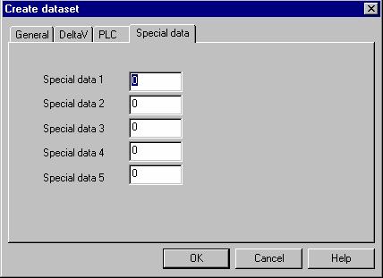
17 4.3.6 Special Data 1-5 Under the Special data tab, the Special data 1 value is used for 5000 and 7000 series register data I/O. For 7000 series registers, the data is transferred as floating point numbers encoded in IEEE format. Floating point numbers are represented in 4 bytes. The byte order of the number is dependent on how the field device stores and transmits it in the command/response packet. In the PSIC, you can change how DeltaV interprets the number by specifying a 0 or 1 in Special data 1 as described below. For example, a 1.0 is represented as 0x3F The PSIC will look at this number as described: Check the field device documentation before configuring this value. Similar word swapping is supported for 5000 series registers which store data as 32 bit numbers. Table 5 Special Data 1 Byte Order 0 (default) 0x3F, 0x80, 0x00, 0x00 1 0x00, 0x00, 0x80, 0x3F Default message framing for Enron Modbus is ASCII. In Master Mode, use the Special data 2 value to change the framing to RTU as described below. Table 6 Special Data 2 Message Framing 0 (default) ASCII Framing 1 RTU Framing In Slave Mode, set Special Data 2 of the first configured dataset to 1. This forces the PSIC to expect RTU message framing. All other Special Data values are unused. 16
18 5 Operational Check 5.1 Scope The following sections provide some assistance to ensure the interface is working properly. 5.2 Verify Hardware and Software Version Number The user can verify that the Enron Modbus I/O driver has been installed using the DeltaV Diagnostics tool. The Diagnostics tool will show the Hardware Revision No. (HwRev) and the Software Revision No. (SwRev). To begin the DeltaV Diagnostic tool select Start-> DeltaV-> Operator-> Diagnostics. In the Diagnostics tool expand the Controller, I/O and then double click on the Programmable Serial Interface Card that has the driver installed. The following information will be displayed: : : : HwRev Hardware Revision 1.1 (or later) SwRev Software Revision P1.13 (or later) 5.3 Verify Configuration Verify port configuration: The serial port must be enabled. User needs to make sure communication settings such as baud rate, parity, and number of data bits match the field device settings. Verify dataset configuration: The datasets configured must be as shown above. 5.4 Verify I/O Communication With Control Studio User can create I/O modules in the control studio to verify correct values are read from the PSIC. For AI and DI data, the values should be changed in the field device and verified that the new data are correctly reported in DeltaV. Similarly, verify that the AO and DO data is being written correctly from DeltaV to the field device. 5.5 Using Diagnostics Verify PSIC communication: Select the PSIC on Diagnostics and press the right mouse button. Select Display Real -Time Statistics from the drop down menu. If the Programmable Serial Interface Card is functioning then the user will see the Valid Responses counter and the Async and/or Sync Transactions counters incrementing. There will not be any error counting up. Verify port statistics: Select the Port on the Programmable Serial Interface Card and press the right mouse button. Then select Display Port Statistics form the drop down menu. Verify that the port communications statistics are being displayed properly and are counting as expected for the protocol s functionality. 17
19 Verify dataset values: Select a dataset and press the right mouse button. Select View Dataset Registers from the Drop down window. Verify that the dataset values are displayed as expected. 5.6 LED Indication The Yellow LED for the port should be on solid when all communications on that port are valid. The Yellow LED should be blinking if there is some valid communications and some communications with errors on that port. The Yellow LED should be OFF if there are no valid communications on that port. 18
20 6 DeltaV Field Device Electrical Interface The electrical interface between DeltaV and field devices conforms to the RS-232 and RS-422/485 standards. Each PSIC has 2 ports, which function independently. The distance between the serial card and the field device can be as much as 5000 feet, per the RS-422/485 standard. When using RS-232, the distance is limited to 50 feet. Section 6.1 shows the pin assignments for the PSIC serial terminal block. 6.1 Pin Assignments for DeltaV PSIC RS-232 Standard Terminal Number Signal Description 1 Port 1 - Isolated Ground (GND) 2 Unused 3 Port 1 Transmit Data (TxD) 4 Unused 5 Port 1 Receive Data (RxD) 6 Unused 7 Port 1 Data Terminal Ready (DTR) 8 Port 1 Data Set Ready (DSR) 9 Port 2 - Isolated Ground (GND) 10 Unused 11 Port 2 Transmit Data (TxD) 12 Unused 13 Port 2 Receive Data (RxD) 14 Unused 15 Port 2 Data Terminal Ready (DTR) 16 Port 1 Data Set Ready (DSR) 19
21 RS-422/485 Half Duplex Standard Terminal Number Signal Description 1 Port 1 - Isolated Ground (GND) 2 Port 1 - Data + 3 Unused 4 Port 1 - Data - 5 Unused 6 Unused 7 Unused 8 Unused 9 Port 2 - Isolated Ground (GND) 10 Port 2 Data + 11 Unused 12 Port 2 - Data - 13 Unused 14 Unused 15 Unused 16 Unused RS-422/485 Full Duplex Standard Terminal Number Signal Description 1 Port 1 - Isolated Ground (GND) 2 Port 1 TxD + 3 Unused 4 Port 1 TxD - 5 Unused 6 Port 1 RxD + 7 Unused 8 Port 1 RxD - 9 Port 2 - Isolated Ground (GND) 10 Port 2 TxD + 11 Unused 12 Port 2 TxD - 13 Unused 14 Port 2 RxD + 15 Unused 16 Port 2 RxD - 20
22 6.2 Wiring Connections In general, the figure below shows the connections between the Field Device and the PSIC termination block. In some cases, RxD and TxD signals need to be swapped to create a NULL cable. This can be done easily at the PSIC termination block. Serial Card Term. Block Enron Modbus Device 25-Pin RS-232 Port P1 P2 Shield 1 (GND) (GND) (TXD) (RXD) (RXD) (DTR) (TXD) (DSR) 8 (DCD) (DSR) (DTR) 4 (RTS) 5 (CTS) Serial Card Term. Block Enron Modbus Device 9-Pin RS-232 Port P1 P2 Shield 1 (GND) (GND) (TXD) (RXD) (RXD) (DTR) (DSR) (TXD) (DSR) (DTR) 7 8 (RTS) (CTS) 21
23 Serial Card Term. Block Enron Modbus Device RS-422/485 Full Duplex P1 P2 Shield (GND) 1 9 (GND) (TXD+) (TXD-) (RXD+) (RXD-) (RXD+) (RXD-) (TXD+) (TXD-) Serial Card Term. Block Enron Modbus Device RS-422/485 Half Duplex P1 P2 Shield (GND) 1 9 (GND) (Data+) (Data-) (Data+) (Data-) 22
24 7 Technical Support For technical support or to report a defect, please give MYNAH Technologies a call at (636) If a defect is discovered, please document it in as much detail as possible and then fax your report to us at (636) You can also send us your questions via to support@mynah.com Thank you for using DeltaV. 23

25 8 Example 8.1 Configuration for PSIC In this configuration, Card 1 is added, and 1 Device is defined under Port 1. Step 1: In the DeltaV Explorer, Right Mouse Click on the I/O entry and select New Card. The following dialog will appear. In this dialog, select Slot Position. In this example, we selected position 01. Click OK to continue. Step 2: 24

26 The new card will be added with 2 ports, P01 and P02. Next, Right Mouse Click on port P01, and select Properties as follows: When Properties are selected, the following dialog will appear, allowing you to configure the port. Configure the values as shown. 25


27 Configure the port as Master as shown above. Configure the communications parameters as shown below, making sure that these match the field device. If the PSIC is to be a Slave to another Enron Modbus master, use the drop-down list and select Slave. 26

28 Click on OK to complete Port Configuration. 27

29 Step 3: Add a device at address 1 under port P01. Right Mouse Click on Port P01 as shown below and select New Device. The following dialog will appear. Add description text and click OK. 28
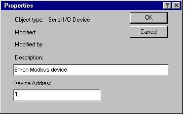
30 29

31 Step 4: Now we must create datasets under the device. The datasets will have different configuration parameters based on the type of Enron registers being accessed. First, Right Mouse Click on DEV01, and select New Dataset as shown below: When New Dataset is selected, the following dialog will appear. We will create 2 input datasets. Configure the parameters as given in Table 5 and shown in the following dialogs: Table 5 Device# Dataset# DeltaV Data Type Device Data Type Start Address Number of Values Special Data Boolean Floating Point
32 Dataset 1 dialogs: 31
33 32
34 Dataset 2 dialogs: 33
35 34
36 Step 5: In this step, we will create 2 output datasets under DEV01. Configure the dataset parameters as shown in Table 6 and dialogs below: Table 6 Device# Dataset# DeltaV Data Device Data Start Number Special Type Type Address of Values Data Boolean Floating Point Dataset 3 dialogs: Dataset 3 has Output mode as 1, indicating single value writes. If a value changes, only that value will be written out. 35
37 36

38 Dataset 2 dialogs: Dataset 4 has Output mode as 0, indicating block writes. When any value in the dataset changes, the entire dataset will be written out. 37
39 This completes the configuration procedure. 38
ASCII Printer Driver Programmable Serial Interface Card Series 2
 ASCII Printer Driver Programmable Serial Interface Card Series 2 USER MANUAL Rev. P1.55 November 6, 2009 DeltaV is a trademark of Emerson Process Management, Inc Emerson Process Management, Inc. 1998,
TI NITP Driver Programmable Serial Interface Card
 TI NITP Driver Programmable Serial Interface Card USER MANUAL Rev. P1.16 August 14, 2006 DeltaV is a trademark of Emerson Process Management, Inc Emerson Process Management, Inc. 1998, 1999. All rights
Square D Sy/Max Driver Programmable Serial Interface Card
 Square D Sy/Max Driver Programmable Serial Interface Card USER MANUAL Rev. P1.10 July 15, 2003 DeltaV is a trademark of Emerson Process Management, Inc Emerson Process Management, Inc. 1998, 1999. All
ASCII Read Driver Programmable Serial Interface Card Series 1
 ASCII Read Driver Programmable Serial Interface Card Series 1 USER MANUAL Rev. P1.10 October 26, 2004 DeltaV is a trademark of Emerson Process Management, Inc Emerson Process Management, Inc. 1998, 1999.
Foxboro HTG Driver Programmable Serial Interface Card Series 2
 Foxboro HTG Driver Programmable Serial Interface Card Series 2 USER MANUAL Rev. P1.59 July 16, 2012 DeltaV is a trademark of Emerson Process Management, Inc Emerson Process Management, Inc. 1998, 1999.
MSA AUER M-292 Programmable Serial Interface Card Series 2
 MSA AUER M-292 Programmable Serial Interface Card Series 2 USER MANUAL Rev. P1.57 August, 2009 DeltaV is a trademark of Emerson Process Management, Inc Emerson Process Management, Inc. 1998, 1999. All
Optichrom 2100 Programmable Serial Interface Card Series 2
 Optichrom 2100 Programmable Serial Interface Card Series 2 USER MANUAL Rev. P1.10 November 29, 2006 DeltaV is a trademark of Emerson Process Management, Inc Emerson Process Management, Inc. 1998, 1999.
Barcode (ASCII Read) Driver for DeltaV Programmable Serial Interface Card
 Driver for DeltaV Programmable Serial Interface Card") Barcode (ASCII Read) Driver for DeltaV Programmable Serial Interface Card USER MANUAL Rev. P1.55 December 27, 2016 DeltaV is a trademark of Emerson Process Management Emerson Process Management 1998, 1999.
Barcode (ASCII Read) Driver for DeltaV Programmable Serial Interface Card USER MANUAL Rev. P1.55 December 27, 2016 DeltaV is a trademark of Emerson Process Management Emerson Process Management 1998, 1999.
Barcode (ASCII Read) Driver for DeltaV Programmable Serial Interface Card Series 2
 Driver for DeltaV Programmable Serial Interface Card Series 2") Barcode (ASCII Read) Driver for DeltaV Programmable Serial Interface Card Series 2 USER MANUAL PRELIMINARY Rev. P1.10 August 19, 2003 DeltaV is a trademark of Emerson Process Management Emerson Process
Barcode (ASCII Read) Driver for DeltaV Programmable Serial Interface Card Series 2 USER MANUAL PRELIMINARY Rev. P1.10 August 19, 2003 DeltaV is a trademark of Emerson Process Management Emerson Process
ABB Gas Chromatograph 3100 Programmable Serial Interface Card Series 2
 ABB Gas Chromatograph 3100 Programmable Serial Interface Card Series 2 USER MANUAL Rev. P1.56 August, 2009 DeltaV is a trademark of Emerson Process Management, Inc Emerson Process Management, Inc. 1998,
Programmable Serial Interface Card Driver Advanced Instruments 3250
 Programmable Serial Interface Card Driver Advanced Instruments 3250 USER MANUAL Rev. P1.55 May 2010 DeltaV is a trademark of Emerson Process Management, Inc Emerson Process Management, Inc. 1998, 1999.
Limitorque DDC-100 Programmable Serial Interface Card Series 2
 Limitorque DDC-100 Programmable Serial Interface Card Series 2 USER MANUAL Rev. P1.55 May 2016 DeltaV is a trademark of Emerson Process Management, Inc Emerson Process Management, Inc. 1998, 1999. All
Virtual RS3 I/O Driver For Series 2 Simplex Programmable Serial Interface Card
 Virtual RS3 I/O Driver For Series 2 Simplex Programmable Serial Interface Card USER MANUAL Rev. P1.56s October 2012 DeltaV is a trademark of Emerson Process Management, Inc Emerson Process Management,
Rotork Pakscan Driver for DeltaV Programmable Serial Interface Card
 Rotork Pakscan Driver for DeltaV Programmable Serial Interface Card USER MANUAL Rev. P1.55 January 2011 DeltaV is a trademark of Emerson Process Management Emerson Process Management. 1998, 1999. All rights
YSI 2700 SELECT Programmable Serial Interface Card Series 2
 YSI 2700 SELECT Programmable Serial Interface Card Series 2 USER MANUAL Rev. P1.57 October 2010 DeltaV is a trademark of Emerson Process Management, Inc Emerson Process Management, Inc. 1998, 1999. All
Robert Shaw Reeltape Model 185A Programmable Serial Interface Card Series 2
 Robert Shaw Reeltape Model 185A Programmable Serial Interface Card Series 2 USER MANUAL Rev. P1.55 April 22, 2011 DeltaV is a trademark of Emerson Process Management, Inc Emerson Process Management, Inc.
Programmable Serial Interface Card Driver Bell-Ennium 7785-P2005 Magnetic Plate Stirrer
 Programmable Serial Interface Card Driver Bell-Ennium 7785-P2005 Magnetic Plate Stirrer USER MANUAL Rev. P1.55 May 2010 DeltaV is a trademark of Emerson Process Management, Inc Emerson Process Management,
AutroSafe Fire Safety System Programmable Serial Interface Card Series 2
 AutroSafe Fire Safety System Programmable Serial Interface Card Series 2 USER MANUAL Rev. P1.56 December 2009 DeltaV is a trademark of Emerson Process Management, Inc Emerson Process Management, Inc. 1998,
Draeger Polytron IR 334 Programmable Serial Interface Card Series 2
 Draeger Polytron IR 334 Programmable Serial Interface Card Series 2 USER MANUAL IOD-1179, Rev. P1.10 September 15, 2008 DeltaV is a trademark of Emerson Process Management, Inc Emerson Process Management,
Rice Lake Weigh Scale Application Programmable Serial Interface Card
 Rice Lake Weigh Scale Application Programmable Serial Interface Card USER MANUAL Rev. P1.55 April, 2009 DeltaV is a trademark of Emerson Process Management, Inc Emerson Process Management, Inc. 1998, 1999.
Rice Lake Weigh Scale Application Programmable Serial Interface Card
 Rice Lake Weigh Scale Application Programmable Serial Interface Card USER MANUAL Rev. P1.56 May, 2016 DeltaV is a trademark of Emerson Process Management, Inc Emerson Process Management, Inc. 1998, 1999.
Foxboro 762C/743CB Controllers Programmable Serial Interface Card
 Foxboro 762C/743CB Controllers Programmable Serial Interface Card USER MANUAL Rev. 1.0 October, 2000 DeltaV is a trademark of Emerson Process Management, Inc Emerson Process Management, Inc. 1998, 1999.
Allen-Bradley Driver for DeltaV Series 2 Programmable Serial Interface Card With Redundancy
 Allen-Bradley Driver for DeltaV Series 2 Programmable Serial Interface Card With Redundancy USER MANUAL December 2016 Rev. P1.63R Allen-Bradley and DeltaV are registered trademarks and DeltaV is a trademark
UniPulse F805-CF Weighing Controller Programmable Serial Interface Card Series 2
 UniPulse Weighing Controller Programmable Serial Interface Card Series 2 USER MANUAL IOD-1177, Rev. P1.11 November 29, 2007 DeltaV is a trademark of Emerson Process Management, Inc Emerson Process Management,
RMV9000 Process Control System RMV9000 to DeltaV Serial Interface User Guide
 RMV9000 Process Control System RMV9000 to DeltaV Serial Interface User Guide Mynah Part Number IOD-1193 August, 2010 (For Series 2 Serial Card) RMV9000 Process Control System RMV9000 to DeltaV Serial Interface
IOD-5101 and IOD-5201 PLC I/O Interface (PIO) Subsystem GE Genius USERS MANUAL. December 21, 2007
 Subsystem GE Genius USERS MANUAL. December 21, 2007") IOD-5101 and IOD-5201 PLC I/O Interface (PIO) Subsystem GE Genius USERS MANUAL December 21, 2007 DeltaV is a trademark of Emerson Process Management, Inc Emerson Process Management, Inc. 2004. All rights
IOD-5101 and IOD-5201 PLC I/O Interface (PIO) Subsystem GE Genius USERS MANUAL December 21, 2007 DeltaV is a trademark of Emerson Process Management, Inc Emerson Process Management, Inc. 2004. All rights
S-series Serial Interface
 DeltaV Distributed Control System Product Data Sheet June 2017 S-series Serial Interface The DeltaV S-series Serial Interface provides a connection between the DeltaV system and other devices. Provides
Modbus TCP Master/Slave Driver for DeltaV Virtual I/O Module
 Modbus TCP Master/Slave Driver for DeltaV Virtual I/O Module ModbusTCP Firmware v3.8.5 or later For Simplex and Redundant Applications USER MANUAL August 2010 Disclaimers MYNAH Technologies 20069. All
TRAINING GUIDE LEVEL 3 MODBUS WRITE IMPORT COMMAND
 OleumTechTM TRAINING GUIDE LEVEL 3 MODBUS WRITE IMPORT COMMAND MUST BE FAMILIAR WITH LEVEL 1 TRAINING MATERIALS BEFORE MOVING FORWARD Doc ID# 80-6010-001b TABLE OF CONTENTS 1. WHAT IS NEW WRITE IMPORT
M-series Serial Interface Series 2
 DeltaV Distributed Control System Product Data Sheet M-series Serial Interface Series 2 The DeltaV Serial Interface provides a connection between the DeltaV system and other devices. Provides seamless
Title: Using the AUX Port.
 Title: Using the AUX Port. Article Number: 1090 Date: 03/15/05 Information in this article applies to: HMI Silver Series (Enhanced Versions OIT Product(s All Controller (PLC Product(s N/A Summary HMI generation
PACSystems* RX3i IC695CMM002 and IC695CMM004
 April 2010 PACSystems* RX3i IC695CMM002 and IC695CMM004 Serial Communications Modules PACSystems * RX3i Serial Communications modules expand the serial communications capabilities of the RX3i system. Serial
Sender Receiver Sender
 EEE 410 Microprocessors I Spring 04/05 Lecture Notes # 19 Outline of the Lecture Interfacing the Serial Port Basics of Serial Communication Asynchronous Data Communication and Data Framing RS232 and other
PACSystems* RX3i IC695CMM002 and IC695CMM004
 May 2010 PACSystems* RX3i IC695CMM002 and IC695CMM004 Serial Communications Modules PACSystems* RX3i Serial Communications modules expand the serial communications capabilities of the RX3i system. Serial
ICC. Modbus RTU Sniffer Driver Manual INDUSTRIAL CONTROL COMMUNICATIONS, INC Industrial Control Communications, Inc.
 INDUSTRIAL CONTROL COMMUNICATIONS, INC. Modbus RTU Sniffer Driver Manual April 3, 2017 2017 Industrial Control Communications, Inc. TABLE OF CONTENTS 1 Modbus RTU Sniffer... 2 1.1 Overview... 2 1.2 Sniffer
Title: Using the AUX Port.
 Title: Using the AUX Port. Article Number: 1090 Date: 07/10/06 Information in this article applies to: HMI Silver Series (Enhanced Versions) OIT Product(s) All Controller (PLC) Product(s) N/A Summary HMI
HART 710. User s Manual Version HART-710 User Manual (Version 1.00, July/2010) PAGE: 1
 PAGE: 1") TM HART 710 User s Manual Version 1.00 HART-710 User Manual (Version 1.00, July/2010) PAGE: 1 Warranty All products manufactured by ICP DAS are under warranty regarding defective materials for a period
TM HART 710 User s Manual Version 1.00 HART-710 User Manual (Version 1.00, July/2010) PAGE: 1 Warranty All products manufactured by ICP DAS are under warranty regarding defective materials for a period
Hardware Manual. PCMCIA 1 Port RS EDITION APRIL 1999
 Hardware Manual 232 232232 PCMCIA 1 Port RS232 1.1 EDITION APRIL 1999 Guarantee. FULL 36 MONTHS GUARANTEE. We guarantee your interface card for a full 36 months from purchase, parts and labour, provided
InLinK HM Setup Software Installation & Operation Manual
 InLinK HM HART Protocol Modem Module with HART Device to Modbus Accumulator for OEM Applications 101-0014 Setup Software Installation & Operation Manual InLink-HM 101-0014 is a complete OEM HART protocol
PACSystems* RX3i IC695CMM002-EG and IC695CMM002CA-EG IC695CMM004-EG, IC695CMM004CA-EG, and IC695CMM004LT-EG
 September 2017 PACSystems* RX3i IC695CMM002-EG and IC695CMM002CA-EG IC695CMM004-EG, IC695CMM004CA-EG, and IC695CMM004LT-EG Serial Communications Modules PACSystems* RX3i Serial Communications modules expand
VersaMax* Serial Communications Module
 Product The VersaMax Serial Communications Module, IC200CMM020, operates as a Modbus RTU Master in a VersaMax I/O Station controlled by a Genius Network Interface Unit or a PROFINET Scanner. Revision Firmware
Automationdirect.com. D i r e c t L o g i c M O D B U S S L A V E F 4 S L V - M B
 Automationdirect.com D i r e c t L o g i c 4 0 5 M O D B U S S L A V E F 4 S L V - M B Order Number: F4-SLVMB-M Automationdirect.com is a Trademark of Automationdirect.com Modbus is a Trademark of Gould
User Manual A08. User Manual
 A08 TABLE OF CONTENTS TABLE OF CONTENTS... 1 1. INTRODUCTION... 2 1.1. Key Features... 3 1.2. OS Requirement... 4 1.3. Specification... 4 1.4. Packing List... 4 2. OVERVIEW... 5 2.1. LED Definition...
Maxiflex Single Harwell NIM M1588 User Manual
 Maxiflex Single Harwell NIM M1588 User Manual SCOPE This document describes the installation, configuration and use of the Maxiflex M1588 Single Harwell NIM. This version of the manual refers to the NIM
DATRAN XL4 RTU Modbus Interface
 Application Note DATRAN XL4 RTU Modbus Interface Introduction The DATRAN RTU Modbus interface is a powerful feature that opens up a huge range of possibilities to interface many types of third party equipment,
EY-CM 721: Communication module with EIA-232 and EIA-485 interfaces, modu721
 Product data sheet 3.1 97.012 EY-CM 721: Communication module with EIA-232 and EIA-485 interfaces, modu721 How energy efficiency is improved SAUTER EY-modulo 5 technology: modular, fast and universal Features
D8000 SERIES QUICK START GUIDE
 D8000 SERIES QUICK START GUIDE Version 1.0 Overview The D8000 series modules require a DC Voltage power supply, a USB cable and an unused computer USB port for proper operation. Connecting the D8000 series
Technical Support Note No. 105 Date August 2002 Rev. 1
 Connecting DeltaV to MTL8000 via the MTL8502-BI-DP Profibus BIM (v2.xx only) 1 Introduction This document walks a user through the steps required to establish communications between the DeltaV Profibus
ISDA/ISDA4 Protocol Driver Manual. Table of Contents
 ISDA/ISDA4 Protocol Driver Manual Table of Contents ISDA 1 Functional Overview... 3 1.1 Master Serial Port(s)... 3 1.2 Module Internal Database... 4 1.2.1 ISDA Serial Port Driver Access to Database...
INTRODUCTION... 2 GENERAL INFORMATION... 3 DEVICE CHARACTERISTICS... 3 LINK CHARACTERISTICS... 3 DRIVER CHARACTERISTICS... 4 CONFORMANCE TESTING...
 MODBU Communication Driver Driver for Serial Communication with Devices Using the Modbus Protocol Contents INTRODUCTION... 2 GENERAL INFORMATION... 3 DEVICE CHARACTERISTICS... 3 LINK CHARACTERISTICS...
Embedded Modbus TCP Module GS11-MT. User Manual REV 1.1. SST Automation.
 Embedded Modbus TCP Module GS11-MT User Manual REV 1.1 SST Automation E-mail: SUPPORT@SSTCOMM.COM WWW.SSTCOMM.COM Catalog 1 About the Embedded Module... 4 1.1 General...4 1.2 Features... 4 1.3 Specifications...4
EtherSeries. EtherSeries CR-2. CR-2-Opto. User s Guide. Revised October 7, 2013 Firmware Version 1.X
 EtherSeries EtherSeries CR-2 & CR-2-Opto User s Guide Revised October 7, 2013 Firmware Version 1.X TABLE OF CONTENTS SECTION 1 - DESCRIPTION... 2 SECTION 2 - SPECIFICATIONS... 4 SECTION 3 - INSTALLATION...
USER S MANUAL. PH232Ex1. #1 RS-232 Serial Port to Ethernet, Terminal Server/Client. Doc No: PH232Ex1-UM-001 IPEX. (IP Electronix)
") USER S MANUAL PH232Ex1 Doc No: PH232Ex1-UM-001 #1 RS-232 Serial Port to Ethernet, Terminal Server/Client IPEX (IP Electronix) Contents 1. INTRODUCTION... 3 2. SPECIFICATIONS... 3 3. PACKAGE CHECKLIST...
USER S MANUAL PH232Ex1 Doc No: PH232Ex1-UM-001 #1 RS-232 Serial Port to Ethernet, Terminal Server/Client IPEX (IP Electronix) Contents 1. INTRODUCTION... 3 2. SPECIFICATIONS... 3 3. PACKAGE CHECKLIST...
ICP PANEL-TEC PEX3000 II
 ICP PANEL-TEC PEX3000 II MODBUS PORT EXPANDER INSTALLATION AND OPERATION GUIDE REVISION HISTORY Revision Date Author Comments 000 29 Aug 2008 Keira Majors Initial release. 001 16 Sep 2008 David Walker
ProtoConvert Modbus RTU / Modbus TCP/IP / BACnet MSTP / BACnet IP / SNMP - Telnet (Lighting Controller) PG
 PG") ProtoConvert Modbus RTU / Modbus TCP/IP / BACnet MSTP / BACnet IP / SNMP - Telnet (Lighting Controller) PG-100-101-102-103-104-110-120 PG-100-101-102-103-104-110-120 is an embedded remote monitoring solution
ProtoConvert Modbus RTU / Modbus TCP/IP / BACnet MSTP / BACnet IP / SNMP - Telnet (Lighting Controller) PG-100-101-102-103-104-110-120 PG-100-101-102-103-104-110-120 is an embedded remote monitoring solution
EY-CM 721: Communication module with EIA-232 and EIA-485 interfaces, modu721
 Product data sheet 97.012 EY-CM 721: Communication module with EIA-232 and EIA-485 interfaces, modu721 How energy efficiency is improved SAUTER EY-modulo 5 technology: modular, fast and universal Features
ACS Stepper _10_Modbus LINEAR SOLUTIONS MADE EASY
 MODBUS RTU & TCP PROGRAMMER S GUIDE ACSI ACS Stepper ACS Servo 3600-4169_10_Modbus LINEAR SOLUTIONS MADE EASY Tolomatic reserves the right to change the design or operation of the equipment described herein
NCOM SERIAL DEVICE SERVER 1XX SERIES USER S MANUAL
 NCOM SERIAL DEVICE SERVER 1XX SERIES USER S MANUAL 2017-07-07 Edition Titan Electronics Inc. Web: www.titan.tw Contents 1. INTRODUCTION... 4 1.1 Key Features... 5 1.2 Specifications... 6 2. PANEL LAYOUT
ICC. Modbus RTU Slave Driver Manual INDUSTRIAL CONTROL COMMUNICATIONS, INC Industrial Control Communications, Inc.
 INDUSTRIAL CONTROL COMMUNICATIONS, INC. Modbus RTU Slave Driver Manual October 30, 2014 2014 Industrial Control Communications, Inc. TABLE OF CONTENTS 1 Modbus RTU Slave... 2 1.1 Overview... 2 1.2 Slave
3.1 I-7560 Pin Assignment and Specifications: Introduction
 3.1 I-7560 Pin Assignment and Specifications: Introduction The I-7560 adds a Windows serial Com port via its USB connection and is compatible with new & legacy RS-232 devices. USB Plug and Play allows
M-series Serial Interface Series 2
 February 2016 Page 1 M-series Serial Interface Series 2 M-series Serial Interface Series 2 The DeltaV Serial Interface provides a connection between the DeltaV system and other devices. Provides seamless
MODBUS Message Protocol MODEL FT3
 MODBUS Message Protocol FOR MODEL FT3 THERMAL MASS FLOWMETER & TEMPERATURE TRANSMITTER Fox Thermal Instruments, Inc. 399 Reservation Road Marina, CA 93933 (831) 384-4300 Fax: (831) 337-5786 104985, Revision
CTI 2573-MOD and CTI 2573-TCM2 SERIAL DEVICE INTERFACE ADAPTER INSTALLATION AND OPERATION GUIDE Version 2.4
 CTI 2573-MOD and CTI 2573-TCM2 SERIAL DEVICE INTERFACE ADAPTER INSTALLATION AND OPERATION GUIDE Version 2.4 CTI Part # 062-00187-024 2573MOD/TCM2IOG $25 ii CTI 2573-MOD/TCM2 Installation and Operation
ICC. Metasys N2 Master Driver Manual INDUSTRIAL CONTROL COMMUNICATIONS, INC Industrial Control Communications, Inc.
 INDUSTRIAL CONTROL COMMUNICATIONS, INC. Metasys N2 Master Driver Manual January 5, 2018 2018 Industrial Control Communications, Inc. TABLE OF CONTENTS 1 Metasys N2 Master... 2 1.1 Overview... 2 1.2 Connections...
GE Fanuc IC695CMM004. Rx3i PacSystem
 GE Fanuc IC695CMM004 http://www.pdfsupply.com/automation/ge-fanuc/rx3i-pacsystem/ic695cmm004 Rx3i PacSystem RX3i serial communications module. Four isolated RS-232/485 port. IC695C IC695CM IC695CMM 919-535-3180
M500 Smart Modem. User s Reference Manual
 M500 Smart Modem User s Reference Manual Software Version 1.2.3 January 23, 2007 Copyright 1997-2007 Micro-Comm, Inc. Table Of Contents Introduction...3 Allen-Bradley DF1 and Modbus Protocol Support...4
NCOM SERIAL DEVICE SERVER 4XX SERIES USER S MANUAL
 NCOM SERIAL DEVICE SERVER 4XX SERIES USER S MANUAL 2017-07-07 Edition Titan Electronics Inc. Web: www.titan.tw Contents 1. INTRODUCTION... 4 1.1 Key Features... 5 1.2 Specifications... 6 2. PANEL LAYOUT
ULTRASONIC SERIAL I/O INTERFACE
 Flow Computer Division ULTRASONIC SERIAL I/O INTERFACE User Manual (QER 02Q017) Form A6133 February 2003 Revision Tracking Sheet February 2003 This manual may be revised from time to time to incorporate
APPLICATION NOTE #xx. Modbus Installation and Troubleshooting for AP9635/AP9635CH Network Management Card By Gary Ware.
 [ APPLICATION NOTE #168 ] APPLICATION NOTE #xx Modbus Installation and Troubleshooting for AP9635/AP9635CH By Gary Ware PROJECT AT A GLANCE Project Type Modbus installation Applications Data centers with
Hardware Manual PCMCIA DUAL RS EDITION MAY 1999
 Hardware Manual 232 232232 PCMCIA DUAL RS232 1.4 EDITION MAY 1999 Guarantee. FULL 36 MONTHS GUARANTEE. We guarantee your interface card for a full 36 months from purchase, parts and labour, provided it
Motion Control Products Application note Connecting CP600 to motion products via Modbus RTU
 Motion Control Products Application note Connecting CP600 to motion products via Modbus RTU AN00200-005 Seamless high speed serial communication between HMI and motion products Introduction The CP600 range
Modbus Installation and Troubleshooting for AP9635/AP9635CH Network Management Card By Gary Ware. Introduction
 [ APPLICATION NOTE #168 ] APPLICATION NOTE #xx Modbus Installation and Troubleshooting for AP9635/AP9635CH By Gary Ware PROJECT AT A GLANCE Project Type Modbus installation Applications Data centers with
MULTICOM. Clarity Hardware. Code/Rev.: M110/80A Date: 8/15/2018. Fax: Petrzilkova 2583/ Prague 5
 MULTICOM Clarity Hardware ENG Code/Rev.: M110/80A Date: 8/15/2018 Phone: +420 251 013 400 DataApex Ltd. Fax: +420 251 013 401 Petrzilkova 2583/13 clarity@dataapex.com 158 00 Prague 5 www.dataapex.com The
CAS IKS Gateway (Modbus RTU/TCP and HTML) Manual
 Manual") CAS-2700-42 IKS to Modbus RTU Gateway CAS 2700-42 IKS Gateway (Modbus RTU/TCP and HTML) Manual CAS 2700-42 IKS Gateway Manual Page 1 of 34 BLANK PAGE CAS 2700-42 IKS Gateway Manual Page 2 of 34 Contents
CAS-2700-42 IKS to Modbus RTU Gateway CAS 2700-42 IKS Gateway (Modbus RTU/TCP and HTML) Manual CAS 2700-42 IKS Gateway Manual Page 1 of 34 BLANK PAGE CAS 2700-42 IKS Gateway Manual Page 2 of 34 Contents
EZL-200F Application Notes (003) Serial Interface (RS232/RS422/RS485)
 Serial Interface (RS232/RS422/RS485)") Application Notes (003) Serial Interface (RS232/RS422/RS485) Version 2.0 Sollae Systems Co., Ltd. 1. Overview supports three serial interfaces: RS232, RS422, and RS485. You can select the interface you
Application Notes (003) Serial Interface (RS232/RS422/RS485) Version 2.0 Sollae Systems Co., Ltd. 1. Overview supports three serial interfaces: RS232, RS422, and RS485. You can select the interface you
ProSoft Technology, Inc. RTU-5/03 Processor for Allen-Bradley SLC Modular Racks Inside this Manual
 Revision : 1.2 Updated : 6/30/04 ProSoft Technology, Inc. RTU-5/03 Processor for Allen-Bradley SLC Modular Racks Catalog Numbers : 3250-L532M RTU-5/03 Processor with 16 K RAM This manual is provided in
S-series Serial Interface
 January 2013 Page 1 The DeltaV provides a connection between the DeltaV system and other devices Provides seamless information interface Plug-and-play easy to use Extends the life of existing equipment
I-7560U/7561U/7563U. User Manual WARRANTY WARNING COPYRIGHT TRADEMARKS CONTACT US
 I-7560U/7561U/7563U User Manual USB tto RS--232//422//485 Converrtterrss Verr.. 1..0,, Decc.. 2013 WARRANTY All products manufactured by ICP DAS are warranted against defective materials for a period of
MGate TM EIP3000 DF1 to EtherNet/IP Gateway User s Manual
 MGate TM EIP3000 DF1 to EtherNet/IP Gateway User s Manual First Edition, June 2009 www.moxa.com/product 2009 Moxa Inc. All rights reserved. Reproduction without permission is prohibited. MGate EIP3000
MODBUS PLUS TO SIEMENS G110/G120/MM440 APPLICATION
 ICP PANEL-TEC MICROBRIDGE INSTALLATION AND OPERATION GUIDE MODBUS PLUS TO SIEMENS G110/G120/MM440 APPLICATION Revision History Revision Date Author Comments 000 3 May 2010 David Walker Initial release.
MGate MB3000 Modbus Gateway User Manual
 MGate MB3000 Modbus Gateway User Manual Sixth Edition, July 2012 www.moxa.com/product 2012 Moxa Inc. All rights reserved. MGate MB3000 Modbus Gateway User s Manual The software described in this manual
Dual Serial Shield User Manual
 Dual Serial Shield User Manual PN: 2050 Berkshire Products, Inc. Phone: 770-271-0088 http://www.bkp-store.com/ Rev: 1.00 Copyright 2013 Table of Contents 1 Introduction... 2 1.1 XB compatibility... 2 2
Wrenchman, Inc Old Hwy. # 8 Suite # 122 New Brighton, Minnesota (651)
") Wrenchman, Inc. 1801 Old Hwy. # 8 Suite # 122 New Brighton, Minnesota 55112 (651) 638-9012 468X Interface Cable Specifications The Interface Cable emulates the Async RS-232 logical interface supported
Wrenchman, Inc. 1801 Old Hwy. # 8 Suite # 122 New Brighton, Minnesota 55112 (651) 638-9012 468X Interface Cable Specifications The Interface Cable emulates the Async RS-232 logical interface supported
Serial console tool. To open the Serial console tool, select Serial console from the Tools drop-down menu in the toolbar.
 Serial console tool The Serial console tool allows you to interact with your radio modules without first discovering them and adding them to the list of radio modules. The layout and functionality of the
Motion Control Products Application note Connecting CP600 to motion products via Modbus RTU
 Motion Control Products Application note Connecting CP600 to motion products via Modbus RTU AN00200-004 Seamless high speed serial communication between HMI and motion products Introduction The CP600 range
User Guide. Date Apr BlueEva+C11/G2. Stollmann. E + V GmbH. User Guide
 Version r02 Date Apr 2009 Author: ta Date saved: 06.04.09 Ref: BlueEva+C11G2_User_Guide_r02.doc Revision: r02 Page 1 of 22 Note This device was developed for the purpose of communication in an office environment.
HRT-710. User s Manual Version HRT-710 User Manual (Version 1.23, Dec/2012) PAGE: 1
 PAGE: 1") TM HRT-710 User s Manual Version 1.23 HRT-710 User Manual (Version 1.23, Dec/2012) PAGE: 1 Warranty All products manufactured by ICP DAS are under warranty regarding defective materials for a period of
TM HRT-710 User s Manual Version 1.23 HRT-710 User Manual (Version 1.23, Dec/2012) PAGE: 1 Warranty All products manufactured by ICP DAS are under warranty regarding defective materials for a period of
WM-120. Serial to Ethernet Module. Serial to Ethernet Module. User Manual. Version 1.0. Infosystem Technology Corporation, Ltd.
 W M - 1 2 0 User Manual Version 1.0 Infosystem Technology Corporation, Ltd. Index 1. Disclaimers... 1. A. Warranty... 2. B. Trademark... 2. 2. Product Information... 3. A. Introduction... 3. B. Features...
This document assumes the user has a reasonable understanding Modbus, RS485 communications, and Rockwell Software s RSLogix product line.
 www.prosoft-technology.com The purpose of this document is to aid in the configuration and setup of the communications between a ProSoft Technology Modbus communications module and an Endress+Hauser Promass
CAS & CAS UL. Modbus RTU Data Client. (Hardware and Software Solutions) Manual
 Manual") CAS-2500-01 & CAS-2500-01-UL ModbusRTU Data Client (Hard and Soft Solutions) CAS 2500-01 & CAS 2500-01-UL Modbus RTU Data Client (Hardware and Software Solutions) Manual Email: dfs@chipkin.com Website:
CAS-2500-01 & CAS-2500-01-UL ModbusRTU Data Client (Hard and Soft Solutions) CAS 2500-01 & CAS 2500-01-UL Modbus RTU Data Client (Hardware and Software Solutions) Manual Email: dfs@chipkin.com Website:
How to set-up and read MOBBUS
 How to set-up and read MOBBUS Before anything can be read from the RTU, the meter must be programmed. During programming up to 16 of the thousands of displays in the meter can be assigned to the RTU. The
D-100 FLOW DISPLAY MODBUS Network Interface Installation Guide
 MODBUS D-100 FLOW DISPLAY MODBUS Network Interface Installation Guide 11451 Belcher Road South, Largo, FL 33773 USA Tel +1 (727) 447-6140 Fax +1 (727) 442-5699 www.onicon.com sales@onicon.com 03-18 0657-9
Product Manual. 8-Port RS-232 USB to Serial Adapter Data Control Box. Coolgear, Inc. Version 1.1 September 2017 Model Number: USB-8COM
 8-Port RS-232 USB to Serial Adapter Data Control Box Product Manual Coolgear, Inc. Version 1.1 September 2017 Model Number: USB-8COM 2 USB-8COM Product Manual Revision History Revision Date Author Comments
M-series DeltaV Controller Interface for RS3 I/O
 January 2013 Page 1 M-series DeltaV Controller Interface for RS3 I/O RS3 I/O Interface Modules DeltaV Railbus Connection RS3 I/O Interface Carrier RS3 I/O Connectors (8) Upgrade your RS3 ControlFiles with
TABLE OF CONTENTS. Communication Functions
 TABLE OF CONTENTS Chapter 1: Chapter 2: Chapter 3: Chapter 4: General Features....................................................... 1-1 Functions......................................................
DGH A3000 Configuration Guide For use with DGH Modules
 DGH A3000 Configuration Guide For use with DGH Modules Revision Date: 12/07/05 Version: 1.00 Contact Information: http://www.dghcorp.com Ph: (603) 622-0452 Fax: (603) 622-0487 Mailing Address: DGH Corporation
MVI46-MCM SLC Platform Modbus Interface Module USER MANUAL. February 5, 2004
 MVI46-MCM SLC Platform Modbus Interface Module USER MANUAL ProSoft Technology, Inc. 1675 Chester Avenue Fourth Floor Bakersfield, CA 93301 (661) 716-5100 (661) 716-5101 Fax prosoft@prosoft-technology.com
using the Data-Linc SRM6000 Spread Spectrum Radio Modem (version 5.39) and Wonderware InTouch 95 (version 7.0.1)
 and Wonderware InTouch 95 (version 7.0.1)") using the Data-Linc SRM6000 Spread Spectrum Radio Modem (version 5.39) and Wonderware InTouch 95 (version 7.0.1) This application guide describes how to setup the modems and drivers so that you can exchange
using the Data-Linc SRM6000 Spread Spectrum Radio Modem (version 5.39) and Wonderware InTouch 95 (version 7.0.1) This application guide describes how to setup the modems and drivers so that you can exchange
Voltage Regulator TAPCON 230 expert
 www.reinhausen.com Voltage Regulator TAPCON 230 expert Supplement 2195774 to Operating Instructions 2136339 Device Profile Document MODBUS 2009 All rights reserved, Maschinenfabrik Reinhausen Unauthorised
EL731 PROFIBUS INTERFACE
 Tel: +1-800-832-3873 E-mail: techline@littelfuse.com www.littelfuse.com/el731 EL731 PROFIBUS INTERFACE Revision 0-A-032816 Copyright 2016 Littelfuse Startco All rights reserved. Document Number: PM-1011-EN