TRAINING GUIDE LEVEL 3 MODBUS WRITE IMPORT COMMAND
|
|
|
- Violet Hubbard
- 5 years ago
- Views:
Transcription

1 OleumTechTM TRAINING GUIDE LEVEL 3 MODBUS WRITE IMPORT COMMAND MUST BE FAMILIAR WITH LEVEL 1 TRAINING MATERIALS BEFORE MOVING FORWARD Doc ID# b
2 TABLE OF CONTENTS 1. WHAT IS NEW WRITE IMPORT TO MODBUS REGISTER HOW TO CREATE A NEW WRITE IMPORT TRIGGER BASE UNIT S DISCRETE OUTPUT - HARDWIRED TRIGGER BASE UNIT S DISCRETE OUTPUT WIRELESS (PEER-TO-PEER) POLL WRITE IMPORT USING A MODBUS MASTER DEVICE WIRELESS (PEER-TO-PEER) CONNECT GATEWAY TO MODBUS MASTER DEVICE GLOSSARY REVISION HISTORY

3 1. WHAT IS NEW WRITE IMPORT TO MODBUS REGISTER A. THE WRITE IMPORT VALUE CAN BE WRITTEN FROM EITHER A MODBUS MASTER DEVICE CONNECTED TO A WIRELESS GATEWAY OR IT CAN BE WRITTEN DIRECTLY FROM BREEZ SOFTWARE ACTING AS A MODBUS MASTER FOR TESTING PURPOSES B. A NEW WRITE IMPORT COMMAND CAN BE ADDED TO EITHER THE INTEGER (16-BIT) OR FLOATING POINT (32-BIT) MODBUS TABLE C. PURPOSE 1. The New Write Import can be used for many different applications. Below are some examples: Modbus Master Device = PLC, RTU, HMI, DCS, EFM, etc. a. Trigger an output: Hardwired (covered in this training) b. Trigger an output: Wirelessly (Peer-to-Peer) (covered in this training) 3
 and or Modbus Master")
 d.")

4 c. Share a process value with other Wireless Gateway(s) and or Modbus Master device(s) in a network (covered in this training) d. Use the Write Import Value to write another command using a Wireless Multi- I/O Module (not covered in this training) 4


5 2. HOW TO CREATE A NEW WRITE IMPORT A. OPEN BREEZ SOFTWARE B. ADD A BASE UNIT WIRELESS GATEWAY USING WIZARD C. DOUBLE-CLICK ON GATEWAY IN THE PROJECT TREE D. CLICK ON MODBUS TAB E. RIGHT-CLICK MOUSE BUTTON IN THE MODBUS WINDOW AND SELECT NEW WRITE IMPORT 5
6 F. WRITE IMPORT WINDOW 1. Create a Name for the command 2. Select Integer (16-bit: adds command to 3000 register block) or Float (32-bit: adds command to 7000 block) 3. Click OK when finished G. VERIFY YOUR NEW WRITE IMPORT IN THE MODBUS WINDOW H. ACTUAL VALUE CAN BE WRITTEN FROM A CONNECTED MODBUS MASTER SOURCE OR BREEZ SOFTWARE 1. To Write a value in BreeZ, see Section 4J 6


7 3. TRIGGER BASE UNIT S DISCRETE OUTPUT - HARDWIRED A. PERFORM PROCEDURE OUTLINED IN SECTION 3 B. DOUBLE-CLICK ON GATEWAY IN THE PROJECT TREE C. CLICK IMPORTS TAB D. RIGHT-CLICK ON THE ROW MB7001 AND SELECT COPY E. CLICK OUTPUTS TAB 7
 2.")

 Mode: inverse function, 0 = On ; All other values = Off 5.")
8 F. RIGHT-CLICK ON FIRST ROW (DOUT1), SELECT PASTE OUTPUT SOURCE G. OPEN EDIT PROPERTIES WINDOW H. CLICK DISCRETE OUTPUTS TAB AND MANAGE SETTINGS 1. Create Name for Output (optional) 2. When none of the boxes are checked: a. Output channel is Off b. Output channel is normally open c. Writing Value of 0 = Off ; All other values = On 3. Initially ON: Checking this box allows the output channel to power on and stay on when Base Unit is powered on or after a hardware reset 4. N.C.(Normally Closed) Mode: inverse function, 0 = On ; All other values = Off 5. Pulsed: the state change is only for a specified duration of time in ms; 1000 = 1 second 6. Click OK or click Config Port Tab when finished 8
 1.")


9 I. IF USING BREEZ TO WRITE OR POLL IMPORT VALUE, THEN SETUP WIRELESS GATEWAY IN MODBUS SLAVE MODE (IF USING OTHER MODBUS MASTER SOURCE, SKIP THIS STEP) 1. In order for BreeZ software to write an import value to a Wireless Gateway, the Config Port Mode must be set to Modbus Slave 2. If the Wireless Gateway is not in Modbus Slave mode, then open the properties window and change the setting 3. Select Config Port Tab and click Modbus Slave and click OK J. CONNECT WIRELESS GATEWAY TO PC AND UPDATE DEVICE 1. Confirm update by checking the Build window 9


10 K. WRITE IMPORT VALUE USING BREEZ 1. Click on Modbus tab, then in the Modbus Window, Right-click on the row and Select Write Value to Register 2. Enter value 3. Verify LED Status Changed on Base Unit s Discrete Output Channel 1 (DO1) 10

11 4. TRIGGER BASE UNIT S DISCRETE OUTPUT WIRELESS (PEER-TO-PEER) A. CREATE A NEW PROJECT FILE WITH 2 BASE UNIT WIRELESS GATEWAYS B. DOUBLE-CLICK ON GATEWAY_1 IN THE PROJECT TREE C. CLICK MODBUS TAB D. RIGHT-CLICK ON MODBUS WINDOW AND SELLECT NEW WRITE IMPORT 11
 or Float")

12 E. WRITE IMPORT WINDOW 1. Create a Name for the command 2. Select Integer (16-bit: add command to 3000 register block) or Float (32-bit: add command to 7000 register block) 3. Click OK when finished F. VERIFY YOUR NEW WRITE IMPORT IN THE MODBUS WINDOW G. CLICK IMPORTS TAB, AND CLICK ROW MB


13 H. CLICK GATEWAY_2 AND CLICK I IMPORT POINTS ICON I. SELECT MAP TO INTEGER TABLE OR FLOATING POINT TABLE OR BOTH J. DOUBLE-CLICK GATEWAY_2, CLICK IMPORTS TAB, RIGHT-CLICK ROW MB7001, AND SELECT COPY 13


14 K. CLICK OUTPUTS TAB, RIGHT-CLICK ON FIRST ROW, AND SELECT PASTE OUTPUT SOURCE L. CONNECT BOTH GATEWAYS TO PC AND UPDATE DEVICES 14
15 M. WRITE IMPORT VALUE USING BREEZ 1. Double-click Gateway_1 in the Project Tree 2. Click on Modbus Tab 3. Click on Modbus Window, Right-click on the row and Select Write Value to Register 4. Enter value 15
 GATEWAY_1")
16 N. VERIFY LED STATUS CHANGE ON GATEWAY_2 DISCRETE OUTPUT CHANNEL 1 (DO1) GATEWAY_1 GATEWAY_2. 16


17 5. POLL WRITE IMPORT USING A MODBUS MASTER DEVICE WIRELESS (PEER-TO-PEER) A. PERFORM PROCEDURE OUTLINED IN SECTION 5 B. CONNECT GATEWAY_2 TO PC C. BE SURE GATEWAY_2 IS IN MODBUS SLAVE MODE TO ENABLE POLLING FEATURE IN BREEZ (SECTION 4H) If you have to re-update Gateway_2 and using BreeZ to write import value, then you must re-write the import value to Gateway_1 after Gateway_2 is updated. D. DOUBLE-CLICK ON GATEWAY_2 IN THE PROJECT TREE E. CLICK MODBUS TAB, RIGHT-CLICK ON THE ROW AND SELLECT POLL MODBUS REGISTER(S) F. READ VALUE 17


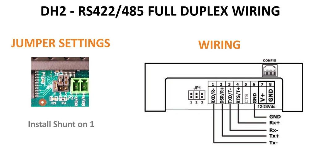
18 6. CONNECT GATEWAY TO MODBUS MASTER DEVICE 1. USE THE FOLLOWING JUMPER AND WIRING TO CONNECT TO MODBUS MASTER DEVICE 18
19 19
20 7. GLOSSARY 16-Bit Integer - a unit of digital information comprised of 16 bits which may be interpreted as: Unsigned: 0 to 65,535 (2 16 1) or Signed: 32,768 ( (2 15 )) to 32,767 (2 15 1) value. 32-Bit Float - a method of representing real numbers in a way that can support a wide range of values. Analog Signal - any continuous signal for which the time varying feature (variable) of the signal is a representation of some other time varying quantity, i.e., analogous to another time varying signal. For example, in sound recording, fluctuations in air pressure strike the diaphragm of a microphone inducing fluctuations in current produced by its coil. This current is said to be an "analog" of the sound. Analog Input - a method for measuring an analog signal. Analog Output - a method for producing an analog signal. ASCII - The American Standard Code for Information Interchange, is a character-encoding scheme based on the ordering of the English alphabet. ASCII codes represent text in computers, communications equipment, and other devices that use text. Baud Rate - A number related to the speed of data transmission in a system. The rate indicates the number of electrical oscillations per second that occurs within a data transmission. The higher the baud rate, the more bits per second are transferred. Bias - while scaling an analog input, the value added to offset the range. Example: range = 500, bias = 100, analog input values scale from 100 (min) to 600 (max). Bit - a contraction of binary digit, is the basic unit of information in computing and telecommunications; it is the amount of information stored by a digital device that exists in one of two possible distinct states 1 or 0, On or Off, etc... Bit Rate - RF data rate or rate that RF data is transmitted over-the-air (9.6k, 115.2k-900MHz or 250k-2.4MHz). Byte - unit of digital information in computing and telecommunications that most commonly consists of eight bits. Channel - one of either 10 hopping sequences (900MHz) or 12 direct sequence channels (2.4GHz) used to isolate radio communications. COM Port - a serial communication physical interface through which information transfers in or out one bit at a time. Configuration Port - the COM Port used to configure an OleumTech device. Count All - a method for increasing an unsigned 16 bit integer each time a discrete input is opened or closed. Count High - a method for increasing an unsigned 16 bit integer each time a discrete input is closed. Count Low - a method for increasing an unsigned 16 bit integer each time a discrete input is opened. CTS - clear to send, a discrete signal indicating permission from the DCE for the DTE to send data to the DCE. DCE - Data Communication Equipment i.e. computers and other intelligent devices. 20
21 Debounce - the duration of time (ms) in which a discrete signal must remain stable prior to acknowledging a change in state from On/Closed to Off/Open and vice versa. Debug - output to the Configuration Port from a connected device providing user insight into its status and operation. Digital (Discrete) Signal - an electrical signal whereby minor fluctuations of the signal are not meaningful unless they cross above or below a discrete threshold, at which point they are said to be On/Closed or Off/Open. DIN Rail Mount - Metal rail of a standard type widely used for mounting circuit breakers and industrial control equipment inside equipment racks. Discrete Input - a method for measuring a digital (discrete) signal. Discrete Output - a method for producing a digital (discrete) signal. Discrete Switch - a device that produces a digital (discrete) signal. DTE Data Terminal Equipment i.e. modems, terminals and any other unintelligent device. Dual Float (Configuration) - Liquid Level Sensor or High Level Switch Sensor set up with two floats to read either product level and interface level liquid levels, or for high and high-high alert notification. EFM - Electronic Flow Meter End Node - OleumTech network device that monitors process conditions. Enhanced Site Security - Enabling site security reduces the chance that transmitted information can be accessed by unauthorized devices or cross-talk between other devices operating in the area. By default, site security is enabled and it is recommended to keep this default setting. Error - Status of the last read operation performed by a Transmitter. A status of 0 = OK. Exports - Values sent to other devices in wireless network. Extended Mode - Used to set a slave ID higher than 255. Firmware - Computer programming instructions that are stored in a read-only memory unit rather than being implemented through software. It resides in an OleumTech wireless gateway, transmitter or expansion modules. Full Duplex - Four wire communication mode using handshaking. Ground (GND) - Ground or earth may be the reference point in an electrical circuit from which other voltages are measured, or a common return path for electric current, or a direct physical connection to the Earth. Group - ID used to configure one or more wireless gateways with its end nodes in a network. Half Duplex - Two wire communication mode which does not use handshaking. Handshaking - An automated process of negotiation that dynamically sets parameters of a communications channel established between two entities before normal communication over the channel begins. Host - Wireless ID of receiver 21
22 Imports - Values received from other devices in wireless network. Initially On - Upon Power cycle or updating device, the discrete output will be closed Interface (Level) - Second level of fluid in tank such as water. Represented by the position of the lower float on the digital liquid level sensor. Interval - Time delay in which the device will transmit data. Jumper - A short length of wire used temporarily to complete a circuit or to bypass a break in a circuit. Represented by small pieces placed on pins of the circuit board Modbus - A Master/Slave protocol used with programmable electronic devices that allows for communication between many devices connected to the same network. Modbus Master - A device that polls (requests and sends) information from one or more Slave devices in a Modbus network. Modbus Module - Used when a port on a receiver is set to Modbus Master mode. Used to read and write values to a Modbus Slave device. Modbus Slave - A device in a Modbus network takes action from a Modbus Master device and responds to it. Node - term used to identify a System Transmitter, configured to communicate with a System Gateway. Node Timeout - Transmitter setting that specifies the number of minutes the node checks for radio-frequency activity. If it does not detect radio-frequency activity within this period, it registers a Read Timeout error. Normally Closed - Digital contact that is closed in normal state. Normally Open - Digital contact that is open in normal state. Output Window - shows messages and data associated with various tasks. Outputs - Values used to source outputs on a device such as analog output, discrete output, or Modbus write registers. Parity - A bit added to a binary code that indicates parity and is used to check the integrity of data. A parity bit is used as the simplest form of error detecting code. PLC - Programmable Logic Controller Port - Communications Port ID on computer used to configure devices. Pressure Transducer - Device used to convert pressure to an analog value Product (Level) - Top level of fluid in tank such as oil. Represented by the position of the top float on a digital liquid level sensor. Project Explorer - Window in the BreeZ Software that shows a tree of the devices in a project file. The name of the project file (current site) appears at the top of the tree, followed by the Wireless Gateway associated with the project file. Transmitters and Modules are grouped below the Wireless Gateway to which they are assigned. Project File - Site specific project configuration set up and saved using BreeZ software. 22
23 Project Name - Name assigned to field site specific project set up and saved using BreeZ software. Pulsed - The discrete output will change state for a specified period of time determined by a Modbus master via a Modbus register write. The value written will be in milliseconds. Range - Max decimal value to be represented by full scale of analog input. RAW Units - Digital representation of an analog signal. Refresh Time - Count that increases every one (1) second. The count is posted each time the corresponding device completes a successful transmission. An unchanging refresh time indicates a failure of the corresponding device. Relay - A device, usually consisting of an electromagnet and an armature, by which a change of current or voltage in one circuit is used to make or break a connection in another circuit or to affect the operation of other devices in the same or another circuit. Retries - Number of times the device will send data in the event of a transmission failure before terminating transmit attempts. RF Timeout - diagnostic indicator for radio communication. To use this value, set the Node Timeout in transmitter's radio setting to double that of the Reading Interval time plus 10 seconds. RS485 - Telecommunications standard for binary serial communications between devices. RS485 allows for serial connections between two or more than devices on a networked system. RS485 Port - RJ45 Jack located on top of Base Unit and Modules, used to communicate Modbus via RS485 protocol. RTS - Ready To Send (232 mode) RTU - Remote Terminal Unit RTU Port - Green terminal ports on Base Unit & DH2, used to communicate Modbus via RS485 or RS232 protocol. RX - Receive (232 mode) RX- - Receive Minus (485 mode) RX+ - Receive Plus (485 mode) Scaled Units - Used to convert an analog signal into desired values Single Float (Configuration) - Liquid Level Sensor or High Level Switch Sensor set up with one float to read either level liquid levels or for alert notification. Site Field location where devices are deployed for use. Site ID Unique, customer assigned identification for site location. Slave ID - ID of the slave device in which Modbus Registers are being requested. Solenoid - A coil of wire, partially surrounding an iron core that is made to move inside the coil by the magnetic field set up by a current: used to convert electrical to mechanical energy, as in the operation of a switch. 23
24 Span - Digital Range of analog to digital converter. Used to signify voltage range of device being used. Split 32-Bit Values - Used to take a 32 bit float register and divide it into two 16 bit registers Stop Bits - Bits sent at the end of every character to allow the receiving signal hardware to detect the end of a character and to resynchronize with the character stream. Turbine - Device that produces digital pulses proportional to the rate at which fluid passes through it. TX - Transmit (232 mode) TX- - Transmit Minus (485 mode) TX Power - Power level at which the radio transmits. TX+ - Transmit Plus (485 mode) V+ - Positive voltage Valve - Used to control the flow of liquids or gas Voltage - Electrical potential or potential difference expressed in volts. Zero - Digital representation 24
25 9. REVISION HISTORY Revision B Removed Mentions of WIO 25
Industrial 1-port RS422/485 Modbus Gateway IMG-110T
 Industrial 1-port RS422/485 Modbus Gateway IMG-110T Presentation Outlines Product Positioning Applications Product Overview Comparison Product Benefits Appendix Product Features 2 / 43 Product Positioning
ICP PANEL-TEC PEX3000 II
 ICP PANEL-TEC PEX3000 II MODBUS PORT EXPANDER INSTALLATION AND OPERATION GUIDE REVISION HISTORY Revision Date Author Comments 000 29 Aug 2008 Keira Majors Initial release. 001 16 Sep 2008 David Walker
Modbus Server - M-Bus (EN ) Gateway for the integration of M-BUS meters with Modbus RTU and TCP based control systems.
 Gateway for the integration of M-BUS meters with Modbus RTU and TCP based control systems.") IntesisBox Server - M-Bus (EN 13757-3) Gateway for the integration of M-BUS meters with and based control systems. Integrate M-Bus meters into your master device or system (BMS, SCADA, PLC, HMI, TouchPanels
IntesisBox Server - M-Bus (EN 13757-3) Gateway for the integration of M-BUS meters with and based control systems. Integrate M-Bus meters into your master device or system (BMS, SCADA, PLC, HMI, TouchPanels
Installation and Programming Manual. Niobrara Research & Development Corporation P.O. Box 3418 Joplin, MO USA
 DUCM DF1 Manual DUCM DF1 Installation and Programming Manual This manual describes the DUCM application for interfacing DF1 slaves to a Modbus or RNIM serial network. Effective: February 16, 2017 Niobrara
Enron Modbus I/O Driver (Series 2) Programmable Serial Interface Card
 Programmable Serial Interface Card") Enron Modbus I/O Driver (Series 2) Programmable Serial Interface Card USER MANUAL Rev. P1.55 June 4, 2009 DeltaV is a trademark of Emerson Process Management, Inc Emerson Process Management, Inc. 1998,
Enron Modbus I/O Driver (Series 2) Programmable Serial Interface Card USER MANUAL Rev. P1.55 June 4, 2009 DeltaV is a trademark of Emerson Process Management, Inc Emerson Process Management, Inc. 1998,
IntesisBox Modbus Server Siemens Synova FC330A
 IntesisBox Modbus Server Siemens Synova FC330A User's Manual V10 r10 eng Intesis Software S.L. 2009. All Rights Reserved. Information in this document is subject to change without notice. The software
KTA-250 Anemometer Alarm Card
 Connects to Davis Instruments DS7911 Anemometer Monitor both the wind speed and direction Interface to PLCs using the Modbus protocol Communicate via RS232 or 2-wire RS485 Interface to PLCs/Instruments
D8000 SERIES QUICK START GUIDE
 D8000 SERIES QUICK START GUIDE Version 1.0 Overview The D8000 series modules require a DC Voltage power supply, a USB cable and an unused computer USB port for proper operation. Connecting the D8000 series
Cutler-Hammer ELC Serial Driver Help Kepware Technologies
 Cutler-Hammer ELC Serial Driver Help 2012 Kepware Technologies 2 Table of Contents Table of Contents 2 3 Overview 3 Device Setup 4 Modem Setup 5 Cable Diagram 5 Data Types Description 7 Address Descriptions
EGW1-IA3-MB User s Manual
 www.exemys.com Rev. 0 1 Products are in constant evolution to satisfy our customer needs. For that reason, the specifications and capabilities are subject to change without prior notice. Updated information
Modbus RTU Serial / Modicon Serial Device Driver Guide
 Modbus RTU Serial / Modicon Serial Device Driver Guide Version 4.5 rev 3 Broadwin Technology, Inc. page 1-1 Table of Contents Modbus RTU Serial / Modicon Serial Device Driver Guide 1-1 1. Modbus RTU Serial
WebAccess Driver Configuration Manual
 WebAccess Modsim MOD_DEV.DLL Driver date: 2017/7/18 English Version 1.0 Revision History Date Version Author Reviewer Description 2018-10-31 1.0 William.Lin Joseph.Chiu Initial Release Modsim / Modicon
using the Data-Linc SRM6000 Spread Spectrum Radio Modem (version 5.39) and Wonderware InTouch 95 (version 7.0.1)
 and Wonderware InTouch 95 (version 7.0.1)") using the Data-Linc SRM6000 Spread Spectrum Radio Modem (version 5.39) and Wonderware InTouch 95 (version 7.0.1) This application guide describes how to setup the modems and drivers so that you can exchange
using the Data-Linc SRM6000 Spread Spectrum Radio Modem (version 5.39) and Wonderware InTouch 95 (version 7.0.1) This application guide describes how to setup the modems and drivers so that you can exchange
GE MDS, LLC. NETio Series. Protocol Communications Supplement. March 2013 Part No A01, Rev. C
 GE MDS, LLC. NETio Series Protocol Communications Supplement March 2013 Part No. 05-4672A01, Rev. C Modbus Protocol NETio Architectural Implementation As described in detail below, the Modbus RTU protocol
IntesisBox Modbus Server Fidelio IP
 IntesisBox Modbus Server Fidelio IP User Manual r1 eng Issue Date: 10/04/2014 Intesis Software S.L. All Rights Reserved. Information in this document is subject to change without notice. The software described
INTELLIS. Modbus Direct Network Monitor
 INTELLIS Modbus Direct Network Monitor System Installation and Operation Manual Phone: (201) 794-7650 Fax: (201)794-0913 Chapter 1 Modbus Protocol Revision History Revision 1.0 30 April, 2002 Initial Version
Industrial 2-port RS422/485 Modbus Gateway IMG-120T
 Industrial 2-port RS422/485 Modbus Gateway IMG-120T u Product Positioning Presentation Outlines u Applications u Product Overview u Comparison u Product Benefits u Product Features 2 / 42 Product Positioning
Golander Peristaltic Pump MODBUS Communication Instruction
 Golander Peristaltic Pump MODBUS Communication Instruction 1 Introduction... 1 2 Modbus Protocol... 2 2.1 Modbus Protocol Model... 2 2.2 Byte Format... 2 2.3 MODBUS Message Timing... 2 2.4 Field... 3 2.5
LoRaWAN Wzzard Utility Quick Guide. v /11/1
 LoRaWAN Wzzard Utility Quick Guide v1.0 2018/11/1 1. Connect LRPv2 Connect LoRaWAN LRPv2 node and your desktop with MicroUSB. An USB virtual COM port will be created in Windows system. If Windows can t
Wireless Transducer MOTOR PROTECTION ELECTRONICS, INC. INSTRUCTION MANUAL. (407) Phone: Website:
 Phone: Website:") Wireless Transducer INSTRUCTION MANUAL MOTOR PROTECTION ELECTRONICS, INC. 2464 Vulcan Road Apopka, Florida 32703 Phone: Website: (407) 299-3825 www.mpelectronics.com Operating Program Revision: 2 Revision
Wireless Transducer INSTRUCTION MANUAL MOTOR PROTECTION ELECTRONICS, INC. 2464 Vulcan Road Apopka, Florida 32703 Phone: Website: (407) 299-3825 www.mpelectronics.com Operating Program Revision: 2 Revision
Modicon Modbus ASCII Serial. Modbus ASCII Serial / Modicon Serial Device Driver Guide. Version 4.5 rev 0 Advantech Corp., Ltd.
 Modbus ASCII Serial / Modicon Serial Device Driver Guide Version 4.5 rev 0 Advantech Corp., Ltd. page 1-1 Table of Contents Modbus ASCII Serial / Modicon Serial Device Driver Guide 1-1 1. Modbus ASCII
TCP/IP TO SERIAL (SINGLE PORT) MODEL No: SerEth-1P VER 2.0
 MODEL No: SerEth-1P VER 2.0") TCP/IP TO SERIAL (SINGLE PORT) MODEL No: SerEth-1P VER 2.0 MILLENNIUM TECHNOLOGIES 440, MASTER MIND 1, ROYAL PALMS ESTATE AAREY MILK COLONY, GOREGAON (EAST), MUMBAI-400065. INDIA. PH: - 91-22-65229736,
TCP/IP TO SERIAL (SINGLE PORT) MODEL No: SerEth-1P VER 2.0 MILLENNIUM TECHNOLOGIES 440, MASTER MIND 1, ROYAL PALMS ESTATE AAREY MILK COLONY, GOREGAON (EAST), MUMBAI-400065. INDIA. PH: - 91-22-65229736,
ICC. Metasys N2 Master Driver Manual INDUSTRIAL CONTROL COMMUNICATIONS, INC Industrial Control Communications, Inc.
 INDUSTRIAL CONTROL COMMUNICATIONS, INC. Metasys N2 Master Driver Manual January 5, 2018 2018 Industrial Control Communications, Inc. TABLE OF CONTENTS 1 Metasys N2 Master... 2 1.1 Overview... 2 1.2 Connections...
ICRM SER User s Guide
 ICRM- 915- SER User s Guide Introduction The ICRM- 915- SER is a high performance serial wireless modem designed to provide reliable long- range communications for SCADA systems. It is supplied in a compact
Getting Started with your D3000M Series Module
 Getting Started with your D3000M Series Module This document contains step-by-step instructions to quickly connect and communicate with your D3000M modules. The modules require a one-time configuration
Lufkin Modbus Serial Driver Help Kepware Technologies
 Lufkin Modbus Serial Driver Help 2012 Kepware Technologies 2 Table of Contents Table of Contents 2 3 Overview 3 Channel Setup 4 Device Setup 5 Cable Diagram 5 Modem Setup 6 Block Sizes 6 Framing 7 Error
Copyright Extract from Conditions of Sale Safety Warning
 KD420 User Manual Copyright 2004-2013 KK Systems Ltd. No reproduction of any part of this document, in any form, is allowed without prior written permission from KKSystems Ltd. All other copyrights and
Document Name: User Manual for SC10MK, Modbus RTU to Modbus TCP Converter
 Document Name: User Manual for SC10MK, Modbus RTU to Modbus TCP Converter Login for the first time, please use http://192.168.1.100 To key in user name and password is for identifying authorization. Default
EQ-DCM User Manual Revision 1.02 Sep 10, 2013
 EQ-DCM User Manual www.equustek.com Revision 1.02 Sep 10, 2013 Contents INTRODUCTION...5 ABOUT THIS MANUAL... 5 INTENDED AUDIENCE... 5 HARDWARE SPECIFICATIONS...6 PHYSICAL SPECIFICATIONS... 6 HARDWARE
MODBUS AND BACNET COMMUNICATION INSTRUCTIONS
 100275719_2000534455_Rev A MODBUS AND BACNET COMMUNICATION INSTRUCTIONS Power-Fin Models: 2500-5000 WARNING This manual must only be used by a qualified heating installer / service technician. Read all
Automationdirect.com. D i r e c t L o g i c M O D B U S S L A V E F 4 S L V - M B
 Automationdirect.com D i r e c t L o g i c 4 0 5 M O D B U S S L A V E F 4 S L V - M B Order Number: F4-SLVMB-M Automationdirect.com is a Trademark of Automationdirect.com Modbus is a Trademark of Gould
115S Serial I/O Module User Manual
 ELPRO Technologies Pty Ltd, 9/12 Billabong Street, Stafford Q 4053, Australia. Tel: +61 7 33528600 Fax: +61 7 33528677 Email: sales@elprotech.com Web: www.elprotech.com Thank you for your selection of
INTEGRATED SYSTEMS AND CONTROL, INC. User s Hardware Manual. PCMNET V 7. xx
 INTEGRATED SYSTEMS AND CONTROL, INC. User s Hardware Manual PCMNET V 7. xx INTEGRATED SYSTEMS AND CONTROLS, INC. PCMNET Users Manual Revised 2/4/2005 2003-2005 Integrated Systems and Control. Inc. PO Box
RTU560 Connections and Settings DIN Rail RTU 560CIG10
 Connections and Settings DIN Rail RTU 560CIG10 Application, characteristics and technical data have to be taken from the hardware data sheet: 560CIG10 1KGT 150 719 Operation The 560CIG10 is a DIN rail
QUCM Limitorque Controller
 QUCM Limitorque Valve Controller Application Manual QUCM Limitorque Controller Installation and Programming Manual This Manual describes the QUCM application for interfacing Limitorque Valve Actuators
ABB Modbus RTU Driver for JMobile
 ABB Modbus RTU Driver for JMobile This document contains the information needed to connect the HMI to ABB controllers using the Modbus RTU standard protocol over a serial communication link. Exor International
Yokogawa Y-Flow Master Database 62102
 Instruction Manual IM 04Q01A04-01E-A Yokogawa Y-Flow Master Database 62102 Yokogawa Y-Flow Master Database 62102 Yokogawa Corporation of America 2 Dart Road, Newnan, Georgia U.S.A. 30265 Tel: 1-800-258-2552
Interface Manual Chemical Injection System
 1 Interface Manual Chemical Injection System SignalFire Numbers: CIJ-xLine (Local Modbus control) CIJ-xLine-Wireless (SignalFire radio) SignalFire Chemical Injection Controller Module The SignalFire Chemical
Bluetooth to RS-232&RS422/485. EX-9132B/BI Bluetooth Adapter Operation Manual
 Bluetooth to RS-232&RS422/485 EX-9132B/BI Bluetooth Adapter Operation Manual First Edition, Jun 2008 Table of Contents 1. Introduction 2 2. Package checklist 3 3. Product Specification 4 4. Product Panel
Instruction Manual. Save These Instructions. Centrifugal Compressor Control System. Model Xe-145F Modbus. Instruction Manual
 80446685 Revision B April 2013 Centrifugal Compressor Control System Model Xe-145F Modbus Instruction Manual Instruction Manual Save These Instructions Contents OVERVIEW...................................................................................................
ALTA Serial Modbus (RTU/ASCII) Gateway Quick Start Guide
 Gateway Quick Start Guide") by ALTA Serial Modbus (RTU/ASCII) Gateway Quick Start Guide For Version 3.3 Information to Users This equipment has been tested and found to comply with the limits for a Class B digital devices, pursuant
by ALTA Serial Modbus (RTU/ASCII) Gateway Quick Start Guide For Version 3.3 Information to Users This equipment has been tested and found to comply with the limits for a Class B digital devices, pursuant
https://www.halvorsen.blog Modbus Hans-Petter Halvorsen
 https://www.halvorsen.blog Modbus Hans-Petter Halvorsen What is Modbus? Modbus is a serial communications protocol originally published by Modicon (now Schneider Electric) in 1979 for use with its programmable
IntesisBox Modbus Server - BACnet/IP Client
 IntesisBox Modbus Server - BACnet/IP Client Gateway for integration of devices into Modbus (RTU and TCP) systems. Integrate Daikin VRV Air Conditioners into your Modbus system (SCADA, BMS, PLC ). For this,
Industrial Serial Device Server
 1. Quick Start Guide This quick start guide describes how to install and use the Industrial Serial Device Server. Capable of operating at temperature extremes of -10 C to +60 C, this is the Serial Device
Modbus ASCII Serial Device Driver Help 2009 Kepware Technologies
 Modbus ASCII Serial Device Driver Help 2009 Kepware Technologies 1 Table of Contents 1 Getting Started... 3 Help Contents... 3 Overview... 3 2 Device Setup... 3 Device Setup... 3 Cable Diagram... 4 Modem
MPU-32 AND FPU-32 TIA-485 NETWORK
 3714 Kinnear Place Saskatoon, SK Canada S7P 0A6 Ph: (306) 373-5505 Fx: (306) 374-2245 www.littelfuse.com/protectionrelays MPU-32 AND FPU-32 TIA-485 NETWORK SEPTEMBER 5, 2006 PRELIMINARY Publication: MPU-32/FPU-32
CS485. User s Manual. Version ZYPEX, Inc.
 CS485 User s Manual Version 2.0 2003 ZYPEX, Inc. Table of Contents Product Description 1 CS485 Configuration & Setup 2 4-wire Operation 2 2-wire Operation 2 Dual Port Operation 2 Carrier Detect 2 Transmitter
G303 RIO (REMOTE I/O) AND LOW END RTU
 AND LOW END RTU") G3 TECHNOLOGIES, INC. G303 RIO (REMOTE I/O) AND LOW END RTU USER DOCUMENTATION / FUNCTIONAL SPEC. Introduction: The G303 is one of several RIO (Remote I/O) products from G3 Technologies designed to fill
G3 TECHNOLOGIES, INC. G303 RIO (REMOTE I/O) AND LOW END RTU USER DOCUMENTATION / FUNCTIONAL SPEC. Introduction: The G303 is one of several RIO (Remote I/O) products from G3 Technologies designed to fill
Maxiflex Single Harwell NIM M1588 User Manual
 Maxiflex Single Harwell NIM M1588 User Manual SCOPE This document describes the installation, configuration and use of the Maxiflex M1588 Single Harwell NIM. This version of the manual refers to the NIM
DATRAN XL4 PLUS RTU Quick Start Guide
 DOC-QSG-XL4-PLUS-RTU DATRAN XL4 PLUS RTU Quick Start Guide Configuring the XL4 Plus RTU The XL4 Plus RTU is configured using software called QTech Workbench. Connection to your PC is via a USB cable (Type
POWERWISE INDAC SETUP MANUAL
 POWERWISE INDAC SETUP MANUAL REVISION: 2.2 INDAC & EMONITOR GATEWAY An installation guide for the PowerWise indac. 2013 PowerWise, Inc. This manual may contain proprietary information about the product
SST-2450 Wireless Modem User s Manual
 SST-2450 Wireless Modem User s Manual Warranty All products manufactured by ICP DAS are warranted against defective materials for a period of one year from the date of delivery to the original purchaser.
Fisher ROC Plus Serial Driver Help Kepware Technologies
 Fisher ROC Plus Serial Driver Help 2014 Kepware Technologies 2 Table of Contents Table of Contents 2 5 Overview 5 Channel Setup 6 Device Setup 7 Tag Import Settings 7 Address Specification 8 Operator Identification
CAS IKS Gateway (Modbus RTU/TCP and HTML) Manual
 Manual") CAS-2700-42 IKS to Modbus RTU Gateway CAS 2700-42 IKS Gateway (Modbus RTU/TCP and HTML) Manual CAS 2700-42 IKS Gateway Manual Page 1 of 34 BLANK PAGE CAS 2700-42 IKS Gateway Manual Page 2 of 34 Contents
CAS-2700-42 IKS to Modbus RTU Gateway CAS 2700-42 IKS Gateway (Modbus RTU/TCP and HTML) Manual CAS 2700-42 IKS Gateway Manual Page 1 of 34 BLANK PAGE CAS 2700-42 IKS Gateway Manual Page 2 of 34 Contents
INTRINSICALLY SAFE DUPLEXER PROTECTION. ELECTRONICS, INC Vulcan Road Apopka, Florida MOTOR INSTRUCTION MANUAL
 INTRINSICALLY SAFE DUPLEXER INSTRUCTION MANUAL MOTOR PROTECTION ELECTRONICS, INC. 2464 Vulcan Road Apopka, Florida 32703 Phone: Website: (407) 299-3825 www.mpelectronics.com Operating Program Revision:
ICC. Modbus RTU Slave Driver Manual INDUSTRIAL CONTROL COMMUNICATIONS, INC Industrial Control Communications, Inc.
 INDUSTRIAL CONTROL COMMUNICATIONS, INC. Modbus RTU Slave Driver Manual October 30, 2014 2014 Industrial Control Communications, Inc. TABLE OF CONTENTS 1 Modbus RTU Slave... 2 1.1 Overview... 2 1.2 Slave
Installation and Programming Manual
 MUCM SATO Printer Application Manual MUCM SATO Installation and Programming Manual This Manual describes the MUCM application for interfacing a SATO M-8400 barcode printer to an MUCM. Effective: 18 May,
ICC. Modbus RTU Sniffer Driver Manual INDUSTRIAL CONTROL COMMUNICATIONS, INC Industrial Control Communications, Inc.
 INDUSTRIAL CONTROL COMMUNICATIONS, INC. Modbus RTU Sniffer Driver Manual April 3, 2017 2017 Industrial Control Communications, Inc. TABLE OF CONTENTS 1 Modbus RTU Sniffer... 2 1.1 Overview... 2 1.2 Sniffer
MVI46-MCM SLC Platform Modbus Interface Module USER MANUAL. February 5, 2004
 MVI46-MCM SLC Platform Modbus Interface Module USER MANUAL ProSoft Technology, Inc. 1675 Chester Avenue Fourth Floor Bakersfield, CA 93301 (661) 716-5100 (661) 716-5101 Fax prosoft@prosoft-technology.com
ISDA/ISDA4 Protocol Driver Manual. Table of Contents
 ISDA/ISDA4 Protocol Driver Manual Table of Contents ISDA 1 Functional Overview... 3 1.1 Master Serial Port(s)... 3 1.2 Module Internal Database... 4 1.2.1 ISDA Serial Port Driver Access to Database...
MODBUS TCP/IP TO MODBUS SERIAL GATEWAY. MODEL No: MGate-1024-DC VER 2.0
 MODBUS TCP/IP TO MODBUS SERIAL GATEWAY MODEL No: MGate-1024-DC VER 2.0 MILLENNIUM TECHNOLOGIES 440, MASTER MIND 1, ROYAL PALMS ESTATE AAREY MILK COLONY, GOREGAON (EAST), MUMBAI-400065. INDIA. PH: - 91-22-65229736,
tsh-700 Series User Manual
 tsh-700 Series User Manual Tiny Serial Port Sharer Aug. 2017 Ver. 1.6 WARRANTY All products manufactured by ICP DAS are warranted against defective materials for a period of one year from the date of delivery
Webinar Organizers. Ryan Shea. Bruce McDuffee. Joe Ryan. Webinar Moderator. Applications Specialist. Product Manager. Precision Digital Corporation
 Webinar Organizers Joe Ryan Product Manager Precision Digital Corporation Ryan Shea Applications Specialist Precision Digital Corporation Bruce McDuffee Webinar Moderator Precision Digital Corporation
HART USER GUIDE FOR GASSONIC OBSERVER-H ULTRASONIC GAS LEAK DETECTOR
 HART USER GUIDE FOR GASSONIC OBSERVER-H ULTRASONIC GAS LEAK DETECTOR This page intentionally left blank. HART USER GUIDE FOR GASSONIC OBSERVER-H ULTRASONIC GAS LEAK DETECTOR HART User Guide for Gassonic
Model 3005 Analog Board. User s Guide
 Siemens Energy, Inc. Oil & Gas Solutions 10730 Telge Road Houston, Texas 77095 USA Document No. SEI-OG-DLS-005 Page 1 of 6 Siemens AG 2011 Table of Contents 1 DESCRIPTION:... 3 2 CONFIGURATION... 3 3 OPERATION...
Bluetooth TO Serial CONVERTER E-P132-B
 Bluetooth TO Serial CONVERTER E-P132-B 1 Table of Contents Introduction..3 Package checklist...4 Product Specification...5 Product Panel Views Description...6 Product Views. 6 DC-In Power Outlet 6 Antenna
IntesisBox Modbus Server - Honeywell XLS 80
 IntesisBox Server - Honeywell XLS 80 Gateway for integration of Honeywell XLS 80 fire panels into (RTU and TCP) enabled control systems. Integrate your Honeywell fire panels into your master device or
VISY-Command. Technical Documentation. with Modbus Protocol. Edition: Version: 1 Art. no.:
 Technical Documentation with Modbus Procol Edition: 2017-04 Version: 1 Art. no.: 350253 FAFNIR GmbH Schnackenburgallee 149 c 22525 Hamburg Germany Tel.: +49 / 40 / 39 82 07-0 Fax: +49 / 40 / 390 63 39
IFC 100 Supplementary instructions
 IFC 100 Supplementary instructions Signal converter for electromagnetic flowmeters Description of Modbus interface Electronic Revision: ER 3.0.xx Modbus version: 1.0.xx KROHNE CONTENTS IFC 100 1 Important
Document Name : User Manual for SC10B : RS232 to Bluetooth Converter.
 Document Name : User Manual for SC10B : RS232 to Bluetooth Converter. SC10B is Bluetooth V.2.0-certified and is backward compatible with v1.1/1.2 devices. You can connect between your computers (Master)
EVO AT SERIES BATTERY CHARGER AT SERIES BATTERY CHARGER COMMUNICATIONS MANUAL. EVO - Microprocessor Controlled Float Battery Charger JA
 EVO P R O D U C T COMMUNICATIONS MANUAL EVO - Microprocessor Controlled Float Battery Charger JA5011-54 NOTICE! WARNING Table of Contents - ATevo TABLE OF CONTENTS 1. INTRODUCTION.....................................................
REL 512 Connectivity With A Harris Westronics RTU Using DNP 3.0
 ABB Application Note Substation Automation and Protection Division REL 512 AN-45A-99 REL 512 Connectivity With A Harris Westronics RTU Using DNP 3.0 ABSTRACT: DNP 3.0 is a popular communication protocol
ENVIRORANGER ERS 500 NVIRORANGER ERS 500 COMMUNICATIONS REFERENCE. Instruction Manual August 2001
 ENVIRORANGER ERS 500 COMMUNICATIONS REFERENCE Instruction Manual August 2001 NVIRORANGER ERS 500 Safety Guidelines Warning notices must be observed to ensure personal safety as well as that of others,
User manual Compact Web PLC WP240 series IEC-line. update:
 User manual Compact Web PLC WP240 series IEC-line update: 16-06-2017 IEC-line by OVERDIGIT overdigit.com 1. General description The WP240 device is a PLC, programmable in IEC61131-3 language using CoDeSys
HART 710. User s Manual Version HART-710 User Manual (Version 1.00, July/2010) PAGE: 1
 PAGE: 1") TM HART 710 User s Manual Version 1.00 HART-710 User Manual (Version 1.00, July/2010) PAGE: 1 Warranty All products manufactured by ICP DAS are under warranty regarding defective materials for a period
TM HART 710 User s Manual Version 1.00 HART-710 User Manual (Version 1.00, July/2010) PAGE: 1 Warranty All products manufactured by ICP DAS are under warranty regarding defective materials for a period
General Specifications. P2-SCM Serial Communications
 General Specifications Module Type Intelligent Modules per Base I/O Points Used Field Wiring Connector Operating Temperature Storage Temperature Humidity Environmental Air Vibration Shock Field to Logic
Features. Target Applications. V1.6 TBS07 RS485 to SDI-12 Converter
 The is an interface box for connecting a PC, data logger or telemetry unit to one or more sensors with SDI-12 interface. The connects to a data logger, telemetry unit or other device with RS485 interface
MODBUS RTU I/O Expansion Modules - Models C267, C277, and C287. Installation and Operations Manual Section 50
 MODBUS RTU I/O Expansion Modules - Models C267, C277, and C287 Installation and Operations Manual 00-02-0651 09-01-09 Section 50 In order to consistently bring you the highest quality, full featured products,
Modbus. Serial communication and control of Rotork actuators. Established Leaders in Valve Actuation. Electric Actuators and Control Systems
 Electric Actuators and Control Systems Established Leaders in Valve Actuation Modbus Serial communication and control of Rotork actuators Publication S117E Issue 04/09 Rotork actuators have been in use
Bluetooth to RS-232 Converter. RT-132B Bluetooth Adaptor Operation Manual
 Bluetooth to RS-232 Converter RT-132B Bluetooth Adaptor Operation Manual First Edition, Nov 2007 Table of Contents 1. Introduction.. 2 2. Package checklist.. 3 3. Product Specification... 4 4. Product
R1M-GH THERMOCOUPLE & DC INPUT MODULE MODEL. Remote I/O R1M Series. (16 points)
") Remote I/O R1M Series THERMOCOUPLE & DC INPUT MODULE (16 points) MODEL MODEL & SUFFIX CODE SELECTION R1MGH2T MODEL Modbus protocol I/O TYPE GH2 : Thermocouple or DC input, 16 points FIELD TERMINAL TYPE
Remote I/O R1M Series THERMOCOUPLE & DC INPUT MODULE (16 points) MODEL MODEL & SUFFIX CODE SELECTION R1MGH2T MODEL Modbus protocol I/O TYPE GH2 : Thermocouple or DC input, 16 points FIELD TERMINAL TYPE
iopro Mirrored IO System
 Ph: (877) 343-8467 Fax: (800) 303-5381 Email: info@ioselect.com iopro Mirrored IO System Quick Start Guide (Ver. 6) www.ioselect.com Page 1 Introduction This document will cover how to use the iopro family
MODBUS AND BACNET COMMUNICATION INSTRUCTIONS
 FB-MODB_100161012_2000020084_Rev L MODBUS AND BACNET COMMUNICATION INSTRUCTIONS Crest Models: 751-6000 WARNING This manual must only be used by a qualified heating installer / service technician. Read
PWR. Power Module Slots
 INSTRUCTION MANUAL ETHERNET INTERFACE MODULE (Modbus/TCP) MODEL BEFORE USE... Thank you for choosing M-System. Before use, please check the contents of the package you received as outlined below. If you
Rotork Pakscan Driver for DeltaV Programmable Serial Interface Card
 Rotork Pakscan Driver for DeltaV Programmable Serial Interface Card USER MANUAL Rev. P1.55 January 2011 DeltaV is a trademark of Emerson Process Management Emerson Process Management. 1998, 1999. All rights
Serial Connection of HC900 Hybrid Controller to 900CS Control Station
 Note: Ethernet connections will provide faster performance than RS-485 HC900 1. Remove HC900 CPU and set S2 Dip Switches for RS-485 unterminated Replace CPU & follow instructions per Installation and User
TRANSDUCER T4311, T4411
 TRANSDUCER T4311, T4411 Programmable temperature transducer for RTD Pt1000 sensor with serial output RS232 and RS485 Instruction manual Instruction Manual for use of transducer: T4311 (RS232), T4411 (RS485)
SCB-C08 USB to RS232/422/485 Converter
 SCB-C08 USB to RS232/422/485 Converter USB Interface RS-232 signal RS-422 signal: RS-485 signal: Cable Type Transmission distance Signal LED Direct power from USB port Power consumption: Compliant with
USER S MANUAL. PH232Ex1. #1 RS-232 Serial Port to Ethernet, Terminal Server/Client. Doc No: PH232Ex1-UM-001 IPEX. (IP Electronix)
") USER S MANUAL PH232Ex1 Doc No: PH232Ex1-UM-001 #1 RS-232 Serial Port to Ethernet, Terminal Server/Client IPEX (IP Electronix) Contents 1. INTRODUCTION... 3 2. SPECIFICATIONS... 3 3. PACKAGE CHECKLIST...
USER S MANUAL PH232Ex1 Doc No: PH232Ex1-UM-001 #1 RS-232 Serial Port to Ethernet, Terminal Server/Client IPEX (IP Electronix) Contents 1. INTRODUCTION... 3 2. SPECIFICATIONS... 3 3. PACKAGE CHECKLIST...
HART/ Modbus TCP Gateway GT200-HT-MT User Manual V 1.2 REV A SST Automation
 HART/ Modbus TCP Gateway GT200-HT-MT User Manual V 1.2 REV A SST Automation E-mail: SUPPORT@SSTCOMM.COM WWW.SSTCOMM.COM Catalog 1 Product Overview... 4 1.1 Product Function...4 1.2 Product Features...
PACSystems* RX3i IC695CMM002 and IC695CMM004
 May 2010 PACSystems* RX3i IC695CMM002 and IC695CMM004 Serial Communications Modules PACSystems* RX3i Serial Communications modules expand the serial communications capabilities of the RX3i system. Serial
icex-cmtm General specs and Installation guide
 icex-cmtm General specs and Installation guide 1. General view 2. Specifications 2.1. Common specs: Ethernet 1 x 10/100Base/T, RJ45 connector with traffic and link LED Serial Interface 1 x RS232/485 USB
CONFIGURATION GUIDE A-B REMOTE I/O LINK ADAPTOR FOR DL-KFR PC CARDS
 CONFIGURATION GUIDE A-B REMOTE I/O LINK ADAPTOR FOR DL-KFR PC CARDS This configuration guide provides programming information for the DL-PC (ISA) and DL-STD (STD 80 and 32) Remote I/O Link applications.
Embedded Modbus TCP Module GS11-MT. User Manual REV 1.1. SST Automation.
 Embedded Modbus TCP Module GS11-MT User Manual REV 1.1 SST Automation E-mail: SUPPORT@SSTCOMM.COM WWW.SSTCOMM.COM Catalog 1 About the Embedded Module... 4 1.1 General...4 1.2 Features... 4 1.3 Specifications...4
Installation and Operating Instructions
 Installation and Operating Instructions Modbus Terminal Board Form MTB IOI 4-12 1.0 DESCRIPTION 1.1 The Modbus Terminal Board is an RS-485, MODBUS RTU slave board capable of reading 33 channels. The first
DKG-210 UNIVERSAL INTERNET GATEWAY UNIT
 DKG-210 UNIVERSAL INTERNET GATEWAY UNIT AC & DC SUPPLY VERSIONS DESCRIPTION The DKG-210 is designed for internet monitoring and control of industrial devices using different protocols through the RAINBOW
A36D/TPSD DNP 3.0 & Modbus SCADA INTERFACE
 SCADA INTERFACE INSTRUCTIONS - OPTION 21P / 21Q - FOR A36D/TPSD SYSTEMS A36D/TPSD DNP 3.0 & Modbus SCADA INTERFACE OPTION 21P / 21Q INSTRUCTIONS This manual is only valid for A36D/TPSD Chargers equipped
TRP-C08. USB to RS232/422/485 Isolated Converter. User s Manual. Printed Sep.2014 Rev 1.4
 TRP-C08 USB to RS232/422/485 Isolated Converter User s Manual Printed Sep.2014 Rev 1.4 Trycom Technology Co.,Ltd No.35, Zhongxing Rd., Guishan Township, Taoyuan County 333, Taiwan. Tel : 886-3-350-3351
FEATURES DESCRIPTION FEATURES
 FEATURES Two High Speed Counters Two Pulse Train Outputs Two Pulse Width Modulation Outputs 24 Sinking or Sourcing Inputs 16 Outputs 1 RS232 Port 2 RS485 Ports Supports Modbus RTU Protocol Communicate
ASCII Printer Driver Programmable Serial Interface Card Series 2
 ASCII Printer Driver Programmable Serial Interface Card Series 2 USER MANUAL Rev. P1.55 November 6, 2009 DeltaV is a trademark of Emerson Process Management, Inc Emerson Process Management, Inc. 1998,