MAPro10 Numerical 3phase over current + earth fault relay
|
|
|
- Dorothy Ramsey
- 5 years ago
- Views:
Transcription

1 MAPro10 Numerical 3phase over current + earth fault relay 1 T
2 S: STANDARD SAFETY STATEMENTS S 1: Attention: The information in the Safety Section of the equipment documentation is intended to ensure that equipment is properly installed and handled in order to maintain it in a safe condition. It is assumed that everyone who will be associated with the equipment will be familiar with safety instructions. When electrical equipment is in operation, dangerous voltages will be present in certain parts of the equipment. Failure to care, incorrect use, or improper use may endanger personnel and equipment and also cause personal injury or physical damage. Before working in the terminal strip area, the equipment must be isolated. Proper and safe operation of the equipment depends on appropriate shipping and handling, proper storage, installation and commissioning, and on careful operation, maintenance and servicing. For this reason only qualified personnel may work on or operate the equipment. S 1.1: Qualified personnel are individuals who: Are familiar with the installation, commissioning, and operation of the equipment and of the system to which it is being connected; Are able to safely perform switching operations in accordance with accepted safety engineering practices and are authorized to energize and de-energize equipment and to isolate, ground, and label it; Are familiar in the care and use of safety apparatus in accordance with safety engineering practices; Are familiar in emergency procedures (first aid). The equipment documentation gives instructions for its installation, commissioning, and operation. However, the manual cannot cover all conceivable circumstances or include detailed information on all topics. In the event of questions or specific problems, do not take any action without proper authorization. Contact the appropriate FMA technical sales office and request the necessary information. S 2: Technical specifications for safety Unless otherwise stated in the equipment technical manual, the following data is applicable: 2 T
3 S 2.1: Protective fuse rating The recommended maximum rating of the external protective fuse for equipments is 16A, high rupture capacity (HRC) Red Spot type NIT, or TIA, or equivalent. Unless otherwise stated in equipment technical manual, the following data is applicable. The protective fuse should be located as close to the unit as possible. CAUTION - CTs must NOT be fused since open circuiting them may produce lethal hazardous voltages. S 2.2: Protective class IEC : 2005, EN : 2006 Class I (unless otherwise specified in the equipment documentation). This equipment requires a protective conductor (earth) connection to ensure user safety. S 2.3: Installation category IEC : 2005, EN : 2006 Installation Category III Distribution level, fixed installation. Equipment in this category is qualification tested at 5 kv peak, 1.2/50 μs, 500 Ω, 0.5 J, between all supply circuits and earth and also between independent circuits. S 2.4: Environment The equipment is intended for indoor installation and use only. If it is required for use in an outdoor environment then it must be mounted in a specific cabinet or housing or front covered with special FMA cover which will enable it to meet the requirements of IEC with the classification of degree of protection IP54 (dust and splashing water protected). Pollution Degree - Pollution Degree 2 Compliance is demonstrated by reference Altitude - Operation up to 2000m to safety standards. IEC :2005 EN : 2006 I: INTRODUCTION I 1: Introducing MAPro10 The MAPro10 range of FMA relays are universal over current and earth fault relays. This type of relays have been designed to control, protect and monitor industrial installations, public distribution networks and substations and for EHV and HV transmission networks. MAPro10 relays provide comprehensive over current protection. In addition to its protective functions, each relay offers control and recording features, such as trip circuit supervision, multi 3 T
4 shot auto reclosing, broken conductor, cold load pick up, negative sequence over current, and under current with blocking facility. They can be fully integrated to a control system so protection, control, data acquisition and recording of faults, events and disturbances can be made available. The relays are equipped on the front panel with a liquid crystal display (LCD) with 2 x 16 back-light alphanumerical characters, a tactile 7 button keypad (to access all settings, clear alarms and read measurements) and 8+1 fully configurable LEDs that indicate the status of MAPro10 relays. In addition, the use of the RS485 communication port makes it possible to read, reinitialize and change the settings of the relays, if required, from a local or remote PC computer loaded with related PC software. Also it is easily possible to access to events, faults, disturbances, contents of settings via the USB front connector. If you have the system password, you will be able to change the settings via this connector. All of the a.m. facilities are possible by the special FMA MAPro PC software installed on a PC or laptop. Its flexibility of use, reduced maintenance requirements and ease of integration allow the MAPro10 range to provide an adaptable solution for the problems of the protection of electric networks. I 2: General considerations I 2.1: Receipt of relays MAPro protective relays, although generally of robust construction, require careful treatment prior to installation on site. Upon receipt, relays should be examined immediately to ensure no damage has been sustained in transit. If damage has been sustained during transit a claim should be made to the transport contractor and also FMA should be promptly notified. Relays that are supplied not mounted and not intended for immediate installation should be returned to their protective Styrofoam case. I 2.2: Electrostatic discharge (ESD) The relays use components that are sensitive to electrostatic discharges. The electronic circuits are well protected by the metal case and the internal module should not be withdrawn unnecessarily. When handling the module outside its case, care should be taken to avoid contact with components and electrical connections. If removed from the case for storage, the module should be placed in an electrically conducting antistatic bag. There are no setting adjustments within the module and it is advised to avoid unnecessary disassembling. Although the printed circuit boards are plugged together, the connectors are a manufacturing aid and not intended for frequent dismantling; in fact considerable effort may be required to separate them. Touching the printed circuit board should be avoided, since complementary metal oxide semiconductors (CMOS) are used, which can be damaged by static electricity discharged from the body. 4 T
5 I 2.3: Handling of electronic equipment A person s normal movements can easily generate electrostatic potentials of several thousand volts. Discharge of these voltages into semiconductor devices when handling electronic circuits can cause serious damage, which often may not be immediately apparent but the reliability of the circuit will have been reduced. The electronic circuits are completely safe from electrostatic discharge when housed in the case. Do not expose them to risk of damage by withdrawing modules unnecessarily. Each module incorporates the highest practicable protection for its semiconductor devices. However, if it becomes necessary to withdraw a module, the following precautions should be taken to preserve the high reliability and long life for which the equipment has been designed and manufactured. 1. Before removing a module, ensure that you are at the same electrostatic potential as the equipment by touching the case which is connected to the protective conductor terminal. 2. Handle the module by its front plate special handle, frame or edges of the printed circuit board. Avoid touching the electronic components, printed circuit track or connectors. 3. Do not pass the module to another person without first ensuring you are both at the same electrostatic potential. Shaking hands achieves equal potential. 4. Place the module on an antistatic surface, or on a conducting surface which is at the same potential as yourself. 5. Store or transport the module in its protective Styrofoam case. If you are making measurements on the internal electronic circuitry of an equipment in service, it is preferable that you are earthed to the case with a conductive wrist strap. Wrist straps should have a resistance to ground between 500kΩ 10MΩ. If a wrist strap is not available you should maintain regular contact with the case to prevent a build-up of static. Instrumentation which may be used for making measurements should be earthed to the case whenever possible. More information on safe working procedures for all electronic equipment can be found in BS5783 and IEC 147-OF. It is strongly recommended that detailed investigations on electronic circuitry or modification work should be carried out in a special handling area such as described in the abovementioned BS and IEC documents. I 2.4: Relay mounting Relays are dispatched either individually or as part of a panel/rack assembly. If an MAL-TB01 test block is to be included it should be positioned at the right-hand side of the assembly (viewed from the front). Modules should remain protected by their metal case during assembly into a panel or rack. For individually mounted relays an outline diagram is supplied in this Technical Guide showing the panel cut-outs and drilling centers. I 2.5: Unpacking Care must be taken when unpacking and installing the relays so that none of the parts is damaged or the settings altered. Relays must only be handled by skilled persons. The installation should be clean, dry and reasonably free from dust and excessive vibration. 5 T
6 The site should be well lit to facilitate inspection. Relays that have been removed from their cases should not be left in situations where they are exposed to dust or damp. This particularly applies to installations which are being carried out at the same time as construction work. I 2.6: Storage If relays are not to be installed immediately upon receipt they should be stored in a place free from dust and moisture in their original cartons. It is better to care about dust which collects on a carton may, on subsequent unpacking, find its way into the relay, or in damp conditions the carton and packing may become impregnated with moisture. Storage temperature: 25 C to +70 C. 6 T
7 I - 3: Main functions The following table shows the functions available for the different models of the MAPro10 range of relays. Functions Ansi MAPro 105 MAPro 104 MAPro 107 MAPro 101 MAPro 102 MAPro 103 3phase 3phase 3phase Single phase earth fault sensitive overcurrent overcurrent overcurrent overcurrent overcurrent earth fault code plus plus plus overcurrent earth fault earth fault earth fault Single phase overcurrent 50/51 X Earth fault overcurrent 50N/51N X Sensitive earth fault overcurrent 3 phase overcurrent + earth fault 64N X 50/51 50N/51N X X X Undercurrent detection 37 X X X Undercurrent blocking logic X X X Negative sequence overcurrent 46 X X Latching output contacts 86 X X X X X X Broken conductor detection X X Cold load pick up X X Trip circuit supervision X Multi shot autoreclose 79 X Setting groups Selective relay & input scheme logic Phase angle measurement X X X Frequency measurement X X X True RMS measurement X X X Negative & positive seq. measurement X X X X X X X X X Max value monitoring X X X Event records X X X X X X Fault records X X X X X X Disturbance records X X X X X X USB front communication X X X X X X Rear RS485 communication X X X X X X No. of digital inputs No. of output relays 8+1(for WD) (for W.D.) 4+1(for W.D.) 4+1(for W.D.) 7 T
8 T: Technical Data & Function Characteristics T 1 Protection Functions T-1.1 Phase over current: -Phase current protection is based on fundamental frequency. -Phase current setting range: 0.1 to 25I n step of 0.01I n -Thresholds: 3 independent levels, I>, I>>, I>>> -I> setting range: 0.1 to 25I n -I>> setting range: 0.1 to 25I n -I>>> setting range: 0.5 to 25I n Note: When I> or I>> threshold is associated to an IDMT curve, it is recommended to set it to max value of 2I n. Note: I>>> threshold can only be assigned to DMT operation. -Hysteresis: 95% -Shortest operation time: <70 msec (Instantaneous operation) -Drop out time: <660 msec -Definite time delay (for trip & reset): 0 to 600 Sec step of 0.01 Sec -IDMT curves for trip: IEC: Short time Inverse (STI) Standard Inverse (SI) Very Inverse (VI) Extremely Inverse (EI) Long Time Inverse (LTI) IEEE: Moderately Inverse (IMI) Very Inverse (IVI) Extremely Inverse (IEI) -IDMT curves for reset (optional): IEEE Moderately Inverse (IMI) 8 T
9 IEEE Very Inverse (IVI) IEEE Extremely Inverse (IEI) -Time multiplier setting: Trip: 0.01 to 1.5 step of 0.01 Reset (optional): 0.01 to 3.2 step of 0.01 T-1.2 Neutral/Earth fault over current protection -Earth current protection is based on fundamental frequency. -Earth current setting range: 0.02 to 8I n step of 0.01I n -Thresholds: 3 independent levels, I e >, I e >>, I e >>> -I e > setting range: 0.02 to 8I en step of I e >> setting range: 0.02 to 8I en step of I e >>> setting range: 0.02 to 8I en step of 0.01 Note: When I e > or I e >> threshold is associated to an IDMT curve, it is Recommended to set it to Max value of 2I en. Note: I e >>> threshold can only be assigned to DMT operation. -Hysteresis: 95% -Shortest operation time: <70 msec (Instantaneous operation) -Drop out time: <60 msec -Definite time delay (for trip & reset): 0 to 600 Sec step of 0.01 Sec -IDMT curves for trip: IEC: Short time Inverse (STI) Standard Inverse (SI) Very Inverse (VI) Extremely Inverse (EI) Long Time Inverse (LTI) IEEE: Moderately Inverse (IMI) Very Inverse (IVI) Extremely Inverse (IEI) 9 T
10 -IDMT curves for reset (optional): IEEE Moderately Inverse (IMI) IEEE Very Inverse (IVI) IEEE Extremely Inverse (IVI) -Time multiplier setting: Trip: 0.01 to 1.5 step of Reset (optional): 0.01 to 3.2 step of T-1.3 Sensitive Earth fault over current protection -Earth current protection is based on fundamental frequency. -Earth current setting range: to 2.5I en step of 0.001I n -Thresholds: 3 independent levels, I se >, I se >>, I se >>> -I se > setting range: to 2.5I en step of I se >> setting range: to 2.5I en step of I se >>> setting range: to 2.5I en step of Note: When I se > or I se >> threshold is associated to an IDMT curve, it is recommended to set it to Max value of 2I en. Note: I se >>> threshold can only be assigned to DMT operation. -Hysteresis: 95% -Shortest operation time: -Drop out time: -Definite time delay (for trip & reset): -IDMT curves for trip: IEC: IEEE: <70 msec (Instantaneous operation) <60 msec 0 to 600 Sec step of 0.01 Sec Short time Inverse (STI) Standard Inverse (SI) Very Inverse (VI) Extremely Inverse (EI) Long Time Inverse (LTI) Moderately Inverse (IMI) Very Inverse (IVI) 10 T
11 Extremely Inverse (IEI) -IDMT curves for reset (optional): IEEE Moderately Inverse (IMI) IEEE Very Inverse (IVI) IEEE Extremely Inverse (IVI) -Time multiplier setting: Trip: 0.01 to 1.5 step of Reset (optional): 0.01 to 3.2 step of T-1.4 Under current protection - This protection is based on fundamental frequency. - Phase under current setting range(i<): 0.02 to 1I n step of Time delay setting range: 0 to 150 Sec step of 0.01 Sec - Hysteresis: 105% - Blocking facility: 1- By digital inputs, 1 or 2 or none 2- By threshold, range: 0 10 In step of 0.1 In T-1.5 Negative sequence over current protection - This protection is based on fundamental frequency. - Current threshold setting range: 0.1 to 25I n - IDMT curves for trip: IEC: Short time Inverse (STI) Standard Inverse (SI) Very Inverse (VI) Extremely Inverse (EI) Long Time Inverse (LTI) IEEE: Moderately Inverse (IMI) Very Inverse (IVI) -Time multiplier setting: to 1.5 step of DMT: 0 to 150 Sec step of 0.01 Sec 11 T
12 -Reset time (definite): T 2: Recording T-2.1 Event recording -Capacity: -Event types: -Data: 0 to 100 Sec step of 0.01 Sec 75 events (saved in log memory) Any change in settings Change in state of digital inputs Automation function alarms Pick up Event label + date & time (accuracy: 10mSec) T-2.2 Fault recording -Capacity: -Fault types: -Data: 10 faults (saved in log memory) Any selected protection trip or alarm Protection label AC measurements (3 phase & earth RMS) Fault magnitude Fault date & time (time accuracy: 10 msec) Also faults can be observed via front display by pressing READ key and scrolling faults by up & down keys Events and faults are recorded in txt format. The accordance of the event and fault files with the original generated ones can be checked by CRC check tab in PC software. T-2.3 Disturbance recording -Capacity: -Record sampling rate: 10 records ( saved in log memory) 16 samples/cycle 12 T

13 -Pre fault time: -post fault time: -Data: -Trigger: 200mSec (10 cycles) 5 Sec.s According to Com trade format Pick up Along with disturbance data another file can be received which contains the No. of relays configured for different protections. Disturbance files can be received or deleted via front USB port by PC Software. T- 2.4 Time and date setting The time and date of relay can be set and updated according to PC time and date by an option of PC software when relay is connected to PC or laptop. The relay time and date can be observed on display by pressing up key when you are not in setting menus. By pressing CLEAR key you will return to main menu. 13 T
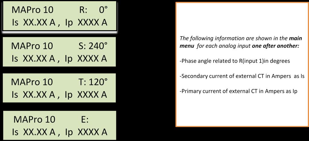
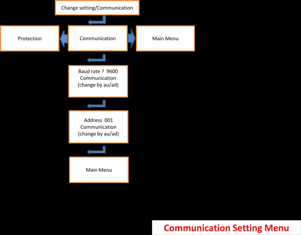
14 T- 2.5 Measurements monitoring: Measurements, containing the following items, are shown on display via measurement menu: - IA(IR), IB(IS), IC(IT) and Ie rms values - I1(positive sequence) and I2(negative sequence) rms values - I2/I1 ratio - In Ifn (true rms minus rms value of fundamental frequency) (means the total rms value of harmonics) - Max of IA, IB, IC from the last resetting. Any time you can reset the Max values by pressing up key when you are observing any of them. -Phase angle(θ ) of I S and I T related to I R in degrees (I R = 0). T 3: Communication T- 3.1 RS485 (rear connector, twisted pair wire) -Protocol: MODBUS RTU -Baud rate: 19200, Connector: screw type/cable shoe -Application: Transfer of information & remote programming T- 3.2 USB (front connector) -Connector: Mini USB standard connector -Application: Information extraction & system programming by a local PC or laptop T 4 Inputs & outputs T- 4.1 AC inputs -Phase current inputs: -Earth current input: -Frequency: 1A & 5A by connection (specified in setting) 1A & 5A by connection (specified in setting) 50 Hz 14 T
15 -Burden: phase: <0.035VA for 1A input <0.4VA for 5A input Earth: <0.01VA for 1A input at 0.1A <0.05VA for 5A input at 0.5A -Current thermal withstand: 1 Sec at 50I n 2 Sec at 25I n Continuous at 4I n T- 4.2 Logic inputs & outputs -Logic inputs: -Logic outputs: T- 4.3 Power supply Contact ratings: Independent optical isolated Burden <10mA Voltage range 35 to 150Vdc Recognition time <5mSec Dry contacts AC max 10A/250V, 50W resistive, 25W Inductive with L/R 40mSec DC max 0.3A/135V, 40W L/R 30mSec Contact operation time: Contact electrical & mechanical operate lifetime: -Aux. voltage range: <10mSec > times (at rated load) 60 to 150Vac/dc, 48 to 150Vdc for MAPro107 others by order -Ripple: <8% -Burden: 3W min, 6.8W max with all output relays energized. T- 4.4 Accuracy -O.C. thresholds: +/- 2.5% -Trip time: Definite time: +/-2%, min: 60mSec Inverse curves: +/-5% for STI, SI, VI, IMI, IVI, +/-8% for LTI, EI, IEI 15 T
16 Accuracy tables related to operate & reset times IEC curves Type of curve Tripping time (in seconds) for TMS =1 IEC 2 x I threshold 10 x I threshold Nominal Min Max Nominal Min Max Accuracy +/ % for nominal tripping time +/- 5 % for nominal tripping time or 70mSec. Whichever is greater or 70mSec. Whichever is greater STI SI VI EI LTI IEEE curves Type of curve Tripping time (in seconds) for TMS =1 IEEE 2 x I threshold 10 x I threshold Nominal Min Max Nominal Min Max Accuracy +/ % for nominal tripping time +/- 5 % for nominal tripping time or 70mSec. Whichever is greater or 70mSec. Whichever is greater IMI IVI IEI DMT Accuracy +/- 1 % or +/-60mSec, whichever is greater Reset time accuracy +/- 1 % or +/-60mSec, whichever is greater 16 T
17 T- 4.5 Inverse time curves -The mathematical inverse tine relations are: STI: t = 0.05 I Is SI: t = 0.14 I Is VI: t = 13.5 ( I Is ) 1 EI: t = 80 I Is LTI: t = 120 ( I Is ) 1 IMI: t = I Is IVI: t = I Is IEI: t = I Is NOTE: In all above relations, TMS (Time Multiplier Setting ) is supposed to be 1, else TMS should be multiplied by t. NOTE: In above relations, t is trip time, I is the value of fundamental frequency of current at tripping time, and I s is the threshold current setting. T- 4.6 Inverse time curves for reset time (optional ) -The mathematical inverse time relations for reset are: IMI: t = I Is IVI: t = I Is IEI: t = I Is NOTE: In all above relations, TMS (Time Multiplier Setting) is supposed to be 1, else t should be multiplied by TMS. 17 T
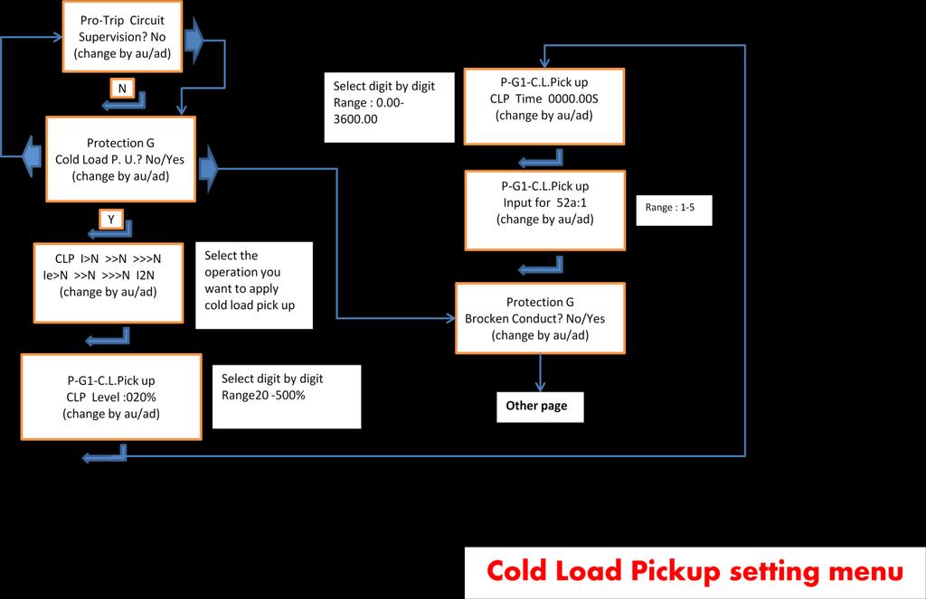
18 T 5: Automation Functions For Protection (not available in MAPro107) T-5.1 Cold load pick up -Range: 20 to 500% of nominal setting step of 1% -Time delay: 0.1 to 3600 Sec step of 0.01 Sec -This function can be considered as a choice for each of the protections, I>,I>>,I>>,I e >,I e >>,I e >>>,I 2 > T-5.2 Multi shot auto recloser -Main shots: 1 to 4 selectable independent shots - This function can be considered as a choice for each of the protections, I>,I>>,I>>,I e >,I e >>,I e >>> -Dead times(d1,d2,d3,d4): 0.01 to 600 Sec step of 0.01 Sec -Reclaim time: 0.02 to 600 Sec step of 0.01 Sec -External control inputs: 3 selectable inputs (for circuit breaker fail detection, external enable/disable, C.B. 52a contact) T Trip circuit supervision & circuit breaker fail detection -Circuit breaker operation time(for open & close): 0,02 to 1 sec Step of 0.01 Sec -Trip relay operation time considered in algorithm: max. 30 msec -One input for C.B.52a contact checking selectable from 1 to 5 -One output relay selectable from 1 t0 8 to announce trip circuit, or circuit breaker operation fail with log reports. 18 T
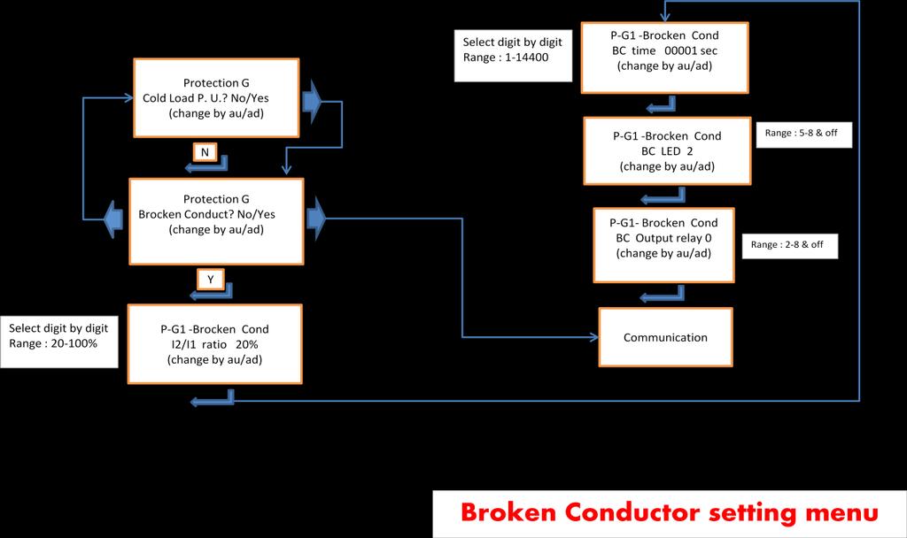
19 T-5.4 Broken conductor detection: -Broken conductor detection is based on measuring & calculation of I 2 /I 1 (fundamental frequency). -Broken conductor threshold: 20% to 100% step of 1% -Broken conductor time delay: 1 to Sec step of 1Sec T-2.6 Switch onto fault (optional) -SOTF function can be activated or not by Y/N in menu. -SOTF period(if activated) after circuit breaker closed: 200 msec -Operation time for trip during SOTF period: 70% of normal operation. T 6: Ordering code: MAPro10X-XXXX No of setting groups 1,2 No of digital outputs ( 1=4,2=8 ) No of digital inputs ( 1=2,2=5 ) Aux. power supply voltage range (1=60 or 48(MAPro107) -150Vdc,2= by order ) 1 : Single phase 2 : Earth fault 3 : Sensitive earth fault 4 : 3 Phase + earth fault without autoreclose 5 : 3 phase + earth fault + Auto reclose 6 : 2 phase + earth + sensitive earth fault 7 : 3phase + earth fault without automation functions 19 T
20 T 7: Connection guide for Mapro104/105 3ph+EF terminal 3Phase +Earth current relay terminal (5 input 8 output) Rev. 2 Back view Terminal No. Description Terminal No. Description Terminal No. Description Terminal No. Description A Current input of phase A 2 1A Current input of phase B 4 1A Current input of phase C 6 1A Current input of Earth 8 5A Current input of phase A 10 5A Current input of phase B 12 5A Current input of phase C 14 5A Current input of Earth Reserved Reserved Reserved 22 Aux power supply + 23 input 24 1A Current input of phase A 29 Input 2 30 Input 5 1A Current input of phase B 31 Input 2 32 Input 5 1A Current input of phase C 33 input 1 34 Input 4 1A Current input of Earth 35 input 1 36 Input 4 5A Current input of phase A 37 5A Current input of phase B 39 5A Current input of phase C 41 5A Current input of Earth 43 WD Relay COM 45 WD Relay N.O. 47 WD Relay N.C. 49 Aux power supply - input RS485 A 26 RS485 B 53 RS485 Ter. RS Res. 28 GND 55 Relay 4 N.O. 38 Input 3 Relay 4 COM 40 Input 3 Relay 3 N.O. 42 Relay 3 COM 44 Relay 2 N.O. 46 Relay 2 N.C. 48 Relay 2 COM 50 Relay 1 N.O. 52 Relay 1 N.C. 54 Relay 1 COM 56 Relay 8 N.O. Relay 8 COM Relay 7 N.O. Relay 7 COM Relay 6 N.O. Relay 6 COM Relay 5 N.O. Relay 5 COM 20 T
21 T 7: Connection guide for MAPro102/103 Earth Fault & Sensitive Earth Fault terminal Sensitive Earth Fault Relay (2 input 4 output) Rev. 2 Back view Terminal No. Description Terminal No. Description Terminal No. Description Terminal No. Description Input 2 30 Reserved Input 2 32 Reserved input 1 34 Reserved 7 1A Current input of Earth 8 1A Current input of Earth 35 input 1 36 Reserved Relay 4 N.O. 38 Reserved Relay A Current 5A Current input of input of 15 Earth 16 Earth 43 WD Relay 17 Reserved 18 COM 45 WD Relay 19 Reserved 20 N.O. 47 WD Relay 21 Reserved 22 Aux power supply + 23 input 24 N.C. 49 Aux power supply - input RS485 A 26 RS485 B 53 RS485 Ter. RS Res. 28 GND 55 COM 40 Reserved Relay 3 N.O. 42 Reserved Relay 3 COM 44 Reserved Relay 2 N.O. 46 Reserved Relay 2 N.C. 48 Reserved Relay 2 COM 50 Reserved Relay 1 N.O. 52 Reserved Relay 1 N.C. 54 Reserved Relay 1 COM 56 Reserved 21 T
22 T 8: Wiring diagrams for MAPro105/104 T 8.1 Phase current is given from 3 CTs & earth current from core balanced CT 22 T
23 MAPro104/105 3 Phase Over current + Earth Fault Relay T 8.2 Phase current is given from 3 CTs & earth current from summation of 3 phase CTs 23 T
24 T 8.3 Phase current is given from 2 CTs & earth current from core balanced CT 24 T
25 T 9: Wiring diagrams for MAPro102/103 MAPro 102/103 Earth Fault / Sensitive Relay 25 T
26 T 10: Wiring diagrams for MAPro101 MAPro 101 Single Phase over current Relay 26 T
27 T 11: Cutout dimensions for MAPro10 relays 27 T
28 T 12: Technical specifications according to standard: T 12.1 Mechanical specifications Design Modular FMA Full draw-out Case 4U (out with automatic CT shorting in the case of the relay) Mounting Rack or flush mounting. Connections Rear (double fasten + M4 screw per connection) Enclosure Protection Front Panel: IEC 60529: 2001: IP 52 Protection (front panel) against dust and dripping water IP 10 Product safety protection for the rear due to live connections on the terminal block Dimensions Height: 4U (177mm) Depth: 250mm Width: 100mm Weight Approx.: 3.0 Kg T 12.2 Environmental conditions Ambient Temperature Range Per IEC : 1988 Operating temperature range: Continuous Withstand: 25 to +55 C (or 13 F to +131 F) Storage Temperature Range: 25 to +70 C (or 28 F to +158 F) Tested as per IEC :2007: 25 C storage (96 hours) 40 C operation (96 hours) IEC : +85 C storage (96 hours) +85 C operation (96 hours) Note 1: The upper limit is permissible for a single 6- hour duration within any 24 hour period. Ambient Humidity Range Humidity: Per IEC : 2001: Per IEC : 2005: 28 T
29 Solar radiation Avoid exposure of the front panel to direct solar radiation. T 12.3 Mechanical environment Vibration Test IEC :1988 Shock and Bump Test IEC :1988 Seismic Test IEC :1993: Class 2. Vibration response Class 2 1g Vibration endurance Class 2 2g Shock response Class 2 10g Shock withstand Class 1 15g Bump Class 1 10g T 12.4 Product safety Compliance is demonstrated by reference to generic safety standards: IEC :2005 EN :2001 T 12.5 Type tests Insulation Rated insulation: 300 PER IEC : 2000, Insulation resistance > 100MΩ at 500Vdc High Voltage (Dielectric) Withstand Per IEC : 2000, 2 kv rms AC, 1 minute: Between all case terminals connected together, and the case earth, and between all terminals of independent circuits (RS232 ports excepted). 2.0kVrms for one minute between all terminals and case earth 2.0kVrms for one minute between all terminals of independent circuits, including contact circuits 1.5kVrms for one minute across dedicated normally open contacts of output relays. 1.5kVrms AC for 1 minute, across open contacts and across open contacts of changeover output relays. Impulse Voltage Withstand Test Per IEC : 2000 The product will withstand without damage impulses of 1.2 / 50 μs, peak value: 5 kv, 0.5J across: 29 T
30 Each independent circuit and the case with the terminals of each independent circuit connected together. Independent circuits with the terminals of each independent circuit connected together. Terminals of the same circuit except normally open metallic contacts. ELECTROMAGNETIC COMPATIBILITY (EMC) DC Supply Interruption Per IEC :1979: The product will withstand a 20ms interruption in the auxiliary voltage in its quiescent condition AC Ripple on DC Supply Per IEC :1979: The product will operate with 12% AC ripple on the DC auxiliary supply without any additional measurement errors Disturbances on AC Supply Per IEC :1994: The products satisfies the requirements of EN for voltage dips and short interruptions. 1 MHz Burst High Frequency Disturbance Test Per IEC : 2008, Class III, Common-mode test voltage: 2.5 kv, Differential test voltage: 1.0 kv, Test duration: 2 s, Source impedance: 200 Ω Electrical Fast Transient or Burst Requirements Per IEC : 2002 The product complies with all classes up to and including Class A 4kV without any mal-operations or additional measurement errors. Fast transient disturbances on terminal block, communications (common mode only) Fast transient disturbances on power supply, I/O signal, data and control lines (common mode only) 2kV, 5ns rise time, 50ns decay time, 5kHz repetition time, 15ms burst, repeated every 300ms for 1min in each polarity, with a 50Ω source impedance. 4kV, 5ns rise time, 50ns decay time, 2.5kHz repetition time, 15ms burst, repeated every 300ms for 1min in each polarity, with a 50Ω source impedance. Per IEC : The product complies with all classes up to and including Level 4 4kV without any mal-operations or additional measurement errors: 30 T
31 Fast transient disturbances on power supply (common mode only) Fast transient disturbances on I/O signal, data and control lines (common mode only) 2kV, 5ns rise time, 50ns decay time, 5kHz repetition time, 15ms burst, repeated every 300ms for 1min in each polarity, with a 50Ω source impedance. 2kV, 5ns rise time, 50ns decay time, 5kHz repetition time, 15ms burst, repeated every 300ms for 1min in each polarity, with a 50Ω source impedance. Immunity to Electrostatic Discharge Per IEC : 1997 & IEC :2001 The product will withstand application of all discharge levels up to the following without Mal - operation: 15 kv discharge in air to user interface, display, and exposed metalwork. 8 kv discharge in air to all communication ports. 8 kv point contact discharge to any part of the front of the product. Conducted Emissions Per EN 55022: 1998: MHz, 79dBμV (quasi peak) 66dBμV (average) MHz, 73 dbμv (quasi peak) 60dBμV (average). Radiated Emissions Per EN 55022: 1998: MHz, 40dBμV/m at 10m measurement distance 230 1GHz, 47dBμV/m at 10m measurement distance. Immunity to Radiated Electromagnetic Energy Per IEC : 2000, Class III & IEC :2002 Test field strength, frequency band 80 to 1000 MHz: 10 V/m, test using AM: 1 khz / 80%, at 80 to 1GHz, 30 V/m, test using AM: 1 khz / 80%, at 80 to 900MHz and 1.4GHz to 2.0GHz Conducted Immunity Per IEC : V/m, test using AM: 1 khz / 80%, at 0.15 to 80MHz, Surge Immunity Per IEC : 2002 Class IV: 4kV common mode 12Ω source impedance, 2kV differential mode 2Ω source impedance power supply Class IV: 4kV common mode 42Ω source impedance, 2kV differential mode 42Ω source impedance Opto inputs, relays, CT, VT Class IV - 4kV common mode 2Ω source impedance applied to cable screen terminal block communications Power Frequency Magnetic Field Immunity 31 T
32 Per IEC :2001, class V: 100A/m quiescent condition, 1000A/m short duration (1-3s) Pulse Magnetic Field Immunity Per IEC :2001, class V: 1000A/m pulse (5 positive, 5 negative) Damped Oscillatory Magnetic Field Per IEC :2001, class V: / 1MHz 2 second burst duration Oscillatory Waves Immunity Per IEC :2001: 2.5kV peak between independent circuits and case earth 1.0kV peak across terminals of the same circuit EMC compliance EN : 1994 EN : 1995 Product Specific Standards were used to establish conformity: EN50263: T
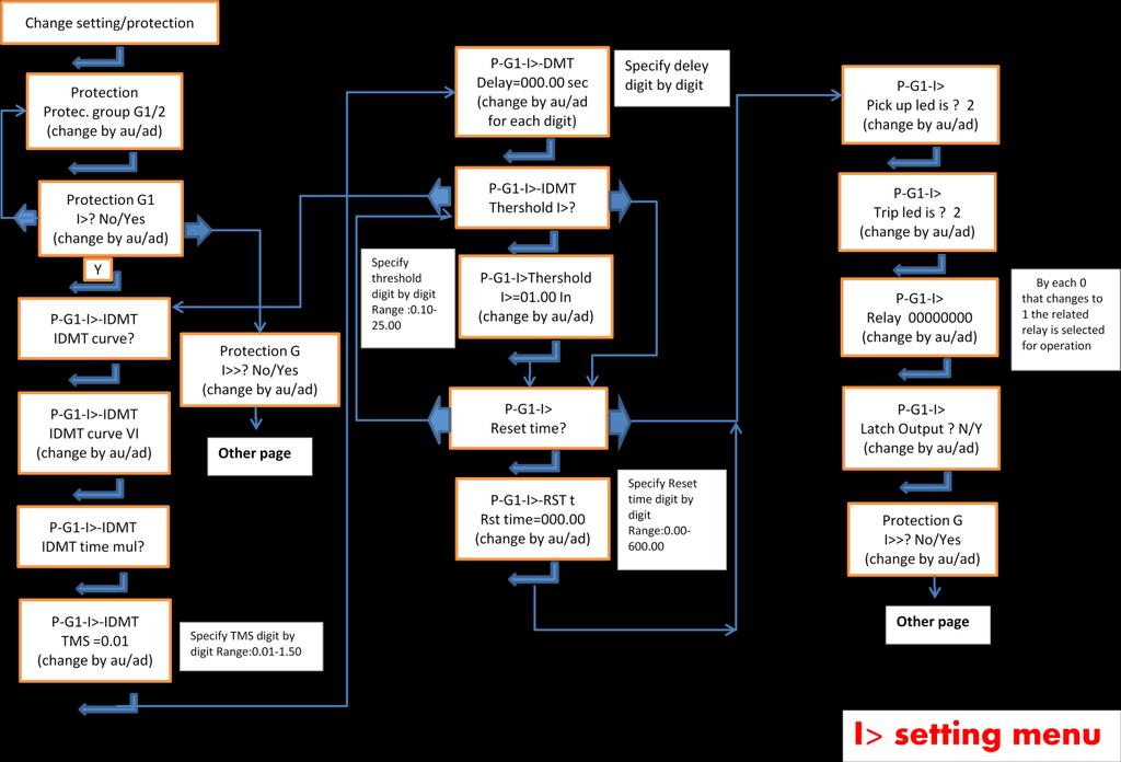
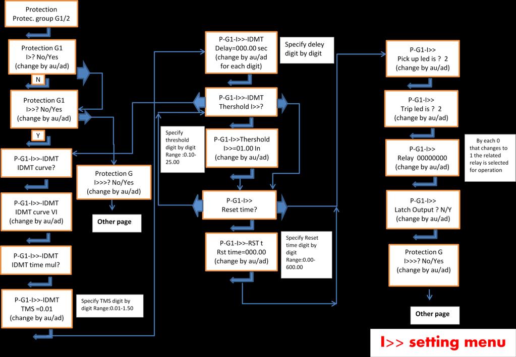
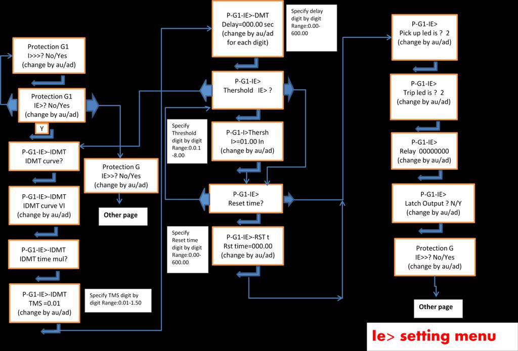
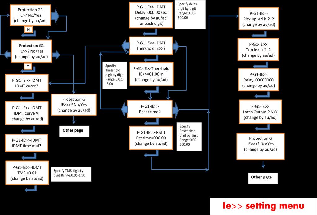
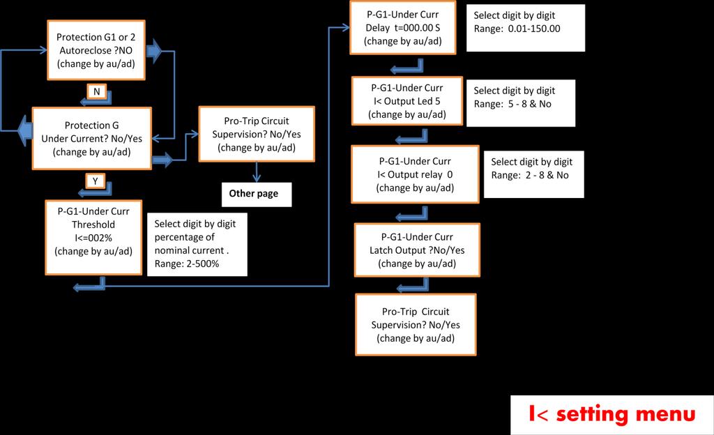
33 U: User guide U 1: Comparison of different models U 1.1: MAPro 105 This type of over current relay has the following protection functions on 3 power lines & earth: - Phase over current, in 3 independent configurable levels I>, I>>, I>>>. All of these levels can be configured in their own menus. I> and I>> levels can protect in DMT (definite time) and eight different IEC & IEEE IDMT curves. Also definite reset time can be defined. Each of 8 LEDs can be selected as pick up or trip or both indications. There are 8 output relays that can be configured in any way that user wants for each level (each of them and any combination of them can be selected). I>>> is specified for fast and fixed time operation. So it dose not contain IDMT and pick up LED and reset time. - Pick up current level is the same as threshold setting and drop out current level is 95% of threshold setting. - For I> & I>>, if IDMT is selected, Pick up level is at threshold setting but time is measured from 1.1 of threshold setting according to selected curve. - Earth fault (earth over current), in 3 independent configurable levels IE>, IE>>, IE>>>. All of these levels can be configured in their own menus. IE> and IE>> levels can protect in DMT (definite time) and eight different IEC & IEEE IDMT curves. Also definite reset time can be defined. Each of 8 LEDs can be selected as pick up or trip or both indications. There are 8 output relays that can be configured in any way that user wants for each level (each of them and any combination of them can be selected). IE>>> is specified for fast and fixed time operation. So it dose not contain IDMT and pick up LED and reset time. - Pick up current level is the same as threshold setting and drop out current level is 95% of threshold setting. - For IE> & IE>>, if IDMT is selected, Pick up level is at threshold setting but time is measured from 1.1 of threshold setting according to selected curve. - Negative sequence over current, one configurable level I2>. I2> can protect in DMT (definite time) and eight different IEC & IEEE IDMT curves. Also definite reset time can be defined. Each of 8 LEDs can be selected as pick up or trip or both indications. There are 8 output relays that can be configured in any way that user wants for each level (each of them and any combination of them can be selected). - Pick up current level is the same as threshold setting and drop out current level is 95% of threshold setting. - If IDMT is selected, Pick up level is at threshold setting but time is measured from 1.1 of threshold setting according to selected curve. - Under current, in one independent configurable level I<. This level can be configured in its own menu. I<operate in DMT (definite time) mode. LEDs 5 to 8 can be selected operate indication. There are 8 output relays that can be configured in any way that user wants for operation of this function. e. - Under current operation can be blocked in two ways: 33 T
34 - 1- By defining a threshold current from configuration menu on relay or setting menu on PC software. In this case if all 3 phase currents are below this defined threshold, under current operation, if is active, will be blocked By selecting inputs 1 or 2 from configuration menu on relay or setting menu on PC software. In this case, if selected input is high, under current operation, if is active, will be blocked. - If both options are active, their effect is with OR logic. - Pick up (descent) current level is the same as threshold setting and drop out current level is 105% of threshold setting. U 1.2: MAPro 104 The functions of MAPro 104 is completely the same as MAPro 105 except that it has 2 digital inputs instead of 5 inputs, and it has 4 configurable output relays instead of 8 relays. So in settings of this type, be careful not to select relays 5 to 8 for any of protection functions. Also the functions TCS and Autoreclose are not existed in MAPro 104. U 1.3: MAPro 101 This type has only one analog input for phase current, so it is applicable for one phase over current protection. The functions are phase over current, I>, I>>, I>>>. The setting related menus are the same as similar functions in MAPro 104 & 105. It has 2 digital inputs, and 4 configurable output relays. So in settings of this type, be careful not to select relays 5 to 8 for any of protection functions. U 1.3: MAPro 102 This type has only one analog input for earth current, so it is applicable for earth over current protection. The functions are earth over current, IE>, IE>>, IE>>>. The setting related menus are the same as similar functions in MAPro 104 & 105. It has 2 digital inputs, and 4 configurable output relays. So in settings of this type, be careful not to select relays 5 to 8 for any of protection functions. U 1.3: MAPro 103 This type has only one analog input for earth current, so it is applicable for sensitive earth over current protection. The functions are sensitive earth over current, IE>, IE>>, IE>>>. The setting related menus are the same as similar functions in MAPro 104 & 105 but the ranges are different, they are as given in technical specifications. It has 2 digital inputs, and 4 configurable output relays. So in settings of this type, be careful not to select relays 5 to 8 for any of protection functions. 34 T
35 U 2: User interfaces U 2.1: Relay Display: 2x16 character LCD with backlight to access settings from relay or observing settings or measurements. LED: one blinking green to show, - external & internal power supply safety - CPU correct operation Eight red LED, all of them not fixed and configurable for any function operation Right & left keys: to move between different menus Up & down keys: to increment or decrement parameters or view fault information or showing date & time CLEAR key: to going to main menu from other menus or reset LED or relays which are operated and latched, if the operation condition is not still continued. To turn off the trip LED which is latched after each trip, keep CLEAR key pushed for 3 seconds. READ key: to access to faults information USB connector, for PC or laptop connection Label tape, positioned on top of front panel, contains the relay main specifications. Back terminal block: the connection and wiring guide is given in T 7, T 8, T 9, T 10 sections. 35 T

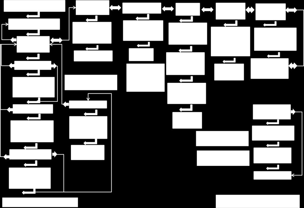
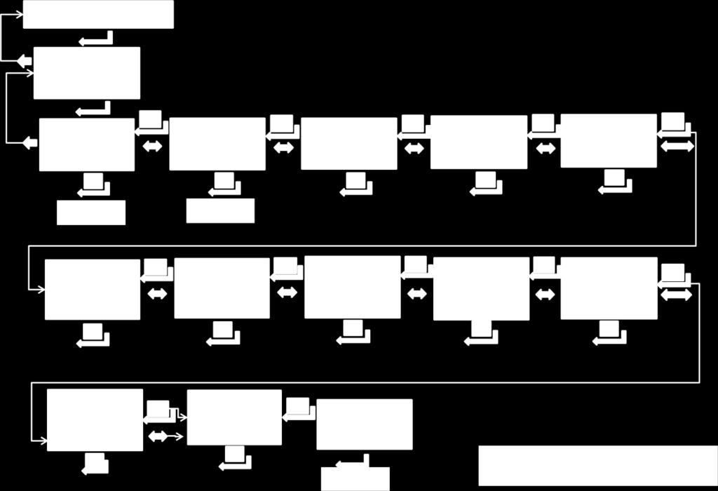
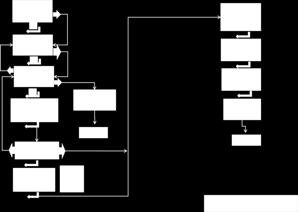
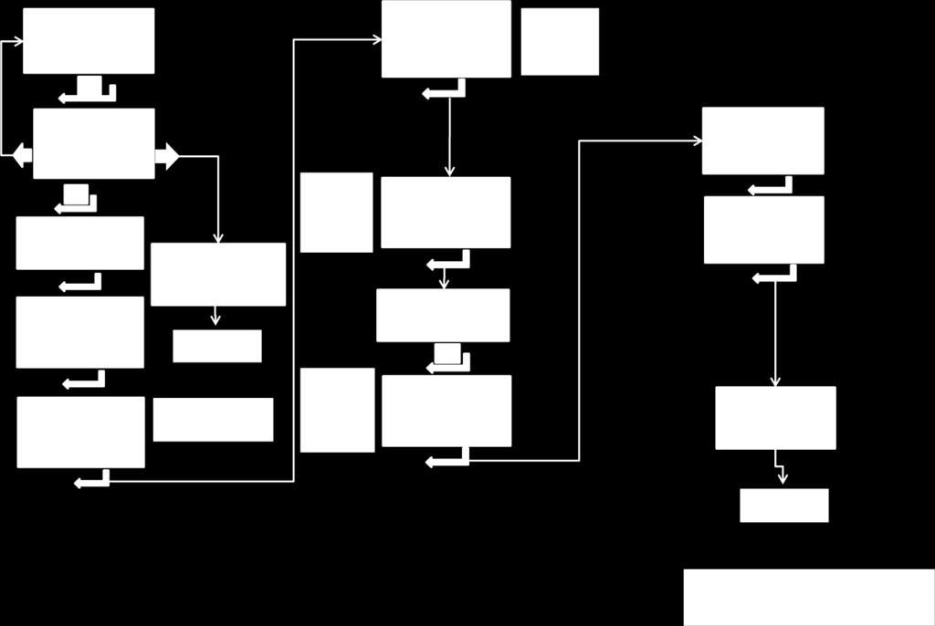
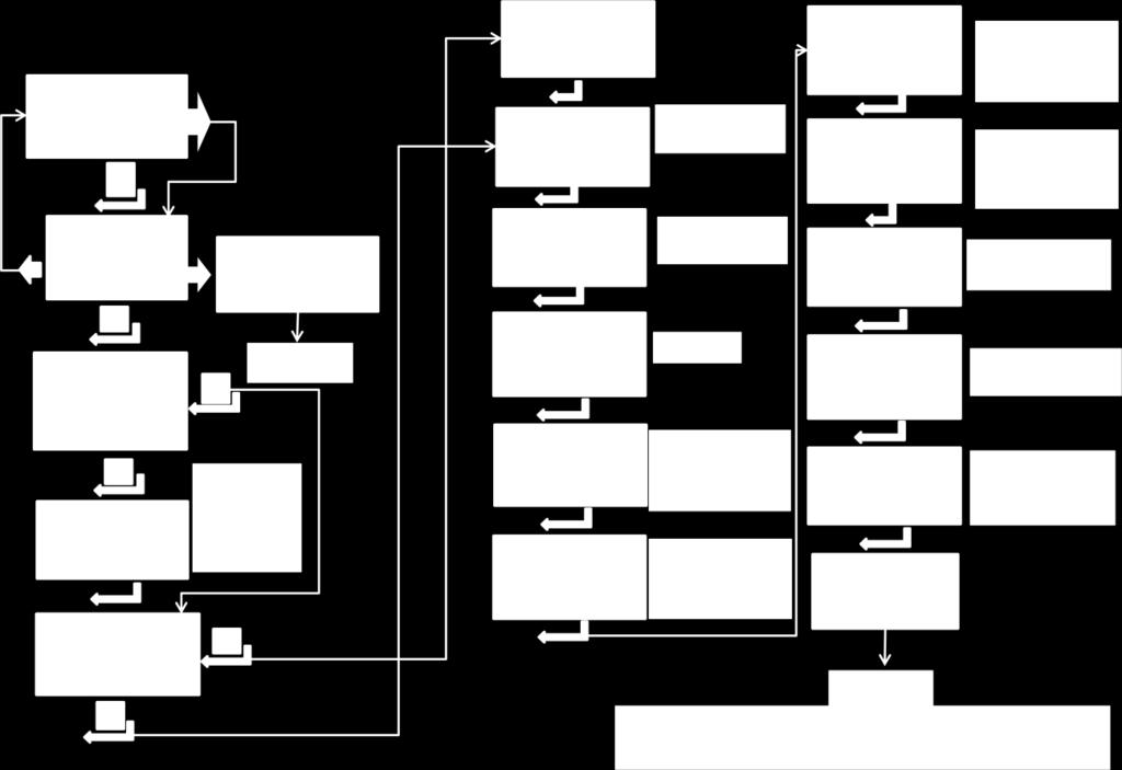
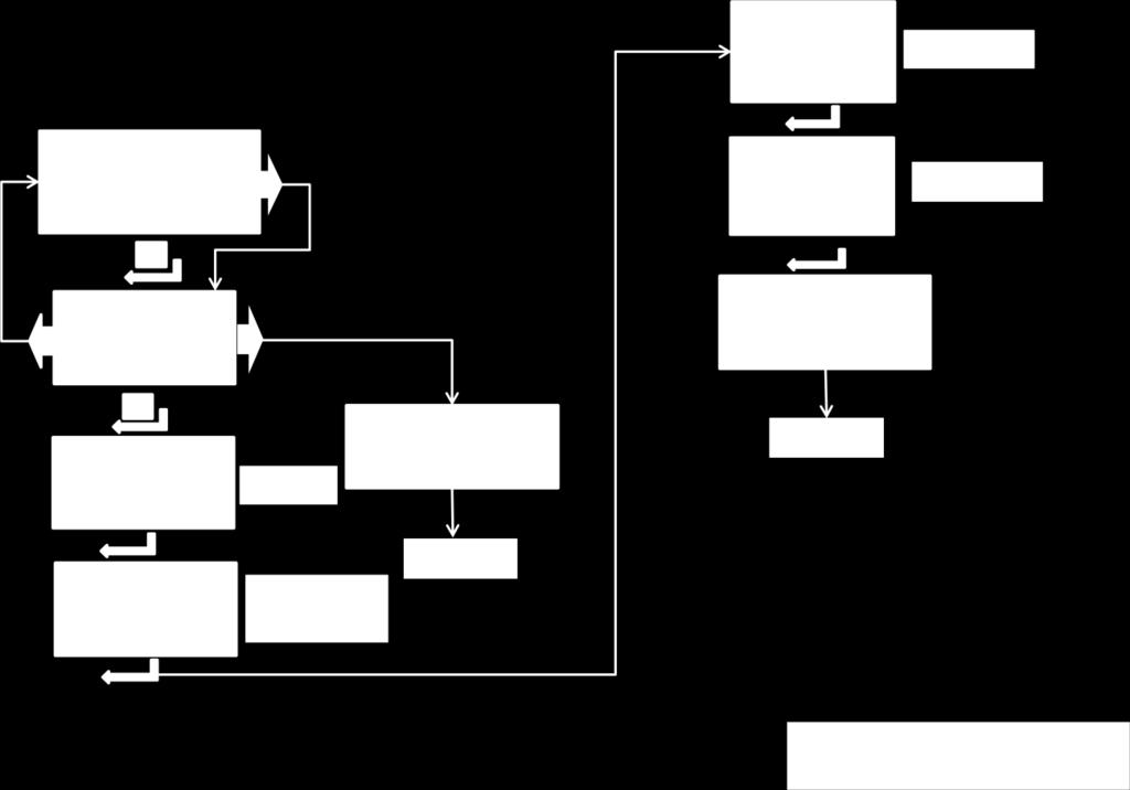
36 U 2.2: Relay settings & menus, using keypad & display 36 T

37 37 T

38 Note: When the relay is in normal condition, by pushing Arrow up key, time is shown on display. When the relay is in normal condition, by pushing READ key, the last 5 faults is shown on display, in this case, by Arrow UP or DOWN the next or previous faults will be shown and by Arrow Right key, the detailed information of existed fault will be shown. 38 T

39 When the relay is in any submenu, by pushing CLEAR key, it returns to main menu. 39 T
40 40 T
41 41 T
42 42 T
43 43 T
44 44 T
45 45 T
46 46 T
47 47 T
48 48 T
49 49 T
50 50 T
51 51 T
52 52 T
53 53 T
54 54 T

55 U 2.3: Relay settings & menus, using PC software MAPro System Setting with PC 55 T
 - Run MAPro Setting.exe Program.")
56 - Connect system with USB cable to PC. - Install driver (FTDI driver) - Run MAPro Setting.exe Program. After it you have below menu. 56 T

57 Use this menu for system setting. If no system is connected, after running the MAPro Setting program you have this menu, By select Ignore, you have 57 T
 you have it s setting menu.")

58 After selecting relay type (3Ph+Earth Over current or sensitive Earth Over current or Over/Under Voltage) you have it s setting menu. For example if select 3Phase +Earth Over current you have In this condition you can set the system in offline mode, save it and use for setting the systems. For example to set I> you will have this menu: 58 T
59 59 T
INSTRUCTION MANUAL TRIP CIRCUIT SUPERVISION RELAY GKAD1
 INSTRUCTION MANUAL TRIP CIRCUIT SUPERVISION RELAY GKAD1 TOSHIBA Corporation 2004 All Rights Reserved. ( Ver. 1.6 ) Safety Precautions Before using this product, please read this chapter carefully. This
Type MVTT 14 and MVTT 15: Static Digital Time delay relays
 Type MVTT 4 and MVTT 5: Static Digital Time delay relays Features 000/ setting range Time settings easily selected by means of thumbwheel switches Provide time delayed pick-up, or drop-off Compact construction
Protection Relays PHASE & RESIDUAL OVERCURRENT
 Protection Relays PHASE & RESIDUAL OVERCURRENT Application The relay type NA016 can be used in radial networks as feeder or power transformer protection. In solidly grounded systems the residual overcurrent
Earth-fault Relay SPAJ 110 C. Product Guide
 Issued: April 1999 Status: Updated Version: C/12.04.2006 Data subject to change without notice Features Low-set neutral overcurrent stage with definite time or inverse time characteristic High-set neutral
SIPROTEC easy 7SJ45 Numerical Overcurrent Protection Relay Powered by CTs
 SIPROTEC easy 7SJ4 Numerical Overcurrent Protection Relay Powered by CTs Function overview Fig. /1 Description The SIPROTEC easy 7SJ4 is a numerical overcurrent protection relay which is primarily intended
Relion 605 series. Self-powered feeder protection REJ603 Product Guide
 Relion 605 series Relion 605 series Relion 605 series Self-powered feeder protection Product Guide Product version: 3.0 Contents 1. Description... 3 2. Relay functions... 3 3. Protection functions... 4
Combined Overcurrent and Earth-fault Relay SPAJ 140 C. Product Guide
 Combined Overcurrent and Earth-fault Product Guide Issued: April 1999 Status: Updated Version: C/18.04.2006 Data subject to change without notice Features Three-phase, low-set phase overcurrent unit with
FL MC 2000E (SM40) LC
 LC") IEC 61850 fiber optic converter with LC fiber optic connection (1310 nm) to convert 100Base-Tx to single- or multi-mode fiber glass Data sheet 3205_en_C 1 Description PHOENIX CONTACT 2014-04-04 2 Features
IEC 61850 fiber optic converter with LC fiber optic connection (1310 nm) to convert 100Base-Tx to single- or multi-mode fiber glass Data sheet 3205_en_C 1 Description PHOENIX CONTACT 2014-04-04 2 Features
GRD130 - FEATURES APPLICATION
 FEATURES Phase undervoltage protection with IDMTL or DTL. Phase overvoltage protection with IDMTL or DTL. Zero phase sequence overvoltage (neutral voltage displacement) protection with IDMTL/DTL. Negative
Feeder protection relay SPAA 121 C. Product Guide
 Issued: April 1999 Status: Updated Version: C/06.03.2006 Data subject to change without notice Features Two-phase low-set phase overcurrent unit with definite time or inverse time characteristic Two-phase
Relion 611 series. 611 series Type Test Certificate
 Relion 611 series 611 series Document ID: 1MRS757466 Issued: 2016-02-22 Revision: B Product version: 2.0 Copyright 2016 ABB. All rights reserved Table of contents Table of contents Section 1 Section
TM3AI4 module TM3-4 analog inputs
 Characteristics module TM3-4 analog inputs Main Range of product Product or component type Range compatibility Analogue input number 4 Analogue input type Complementary Analogue input resolution Permissible
TM3DI16 module TM3-16 inputs
 Characteristics module TM3-16 inputs Main Range of product Product or component type Range compatibility Jun 30, 2018 Modicon TM3 Discrete input module Modicon M241 Modicon M251 Modicon M221 Discrete input
TM221M16TG controller M IO transistor PNP spring
 Characteristics controller M221 16 IO transistor PNP spring Main Range of product Product or component type [Us] rated supply voltage Discrete input number Analogue input number Discrete output type Discrete
Combined Overcurrent and Earth-fault Relay SPAJ 141 C. Product Guide
 Combined Overcurrent and Earth-fault Product Guide Issued: April 1999 Status: Updated Version: C/19.04.2006 Data subject to change without notice Features Three-phase, low-set phase overcurrent unit with
TM3TI8T module TM3-8 inputs temperature
 Characteristics module TM3-8 inputs temperature Main Range of product Product or component type Range compatibility Analogue input number 8 Analogue input type Complementary Analogue input resolution Input
TM3TI4 module TM3-4 inputs temperature
 Characteristics module TM3-4 inputs temperature Main Range of product Product or component type Range compatibility Analogue input number 4 Analogue input type Complementary Analogue input resolution Permissible
GRD110 FEATURES APPLICATION
 FEATURES Overcurrent protection for phase and earth faults with IDMTL or DTL. Three instantaneous elements with DTL. Programmable reset characteristics. Sensitive earth fault protection (SEF). Restricted
1S20. Arc Fault Monitor Relay. Features. Introduction. ARC Fault Protection
 Technical Bulletin Arc Fault Monitor Relay Features Compact, economic design Simple panel mounting for retrofit applications Two or three arc sensor inputs Two high speed tripping duty arc sense output
Sensitive Earth-fault Relay SPAJ 111 C. Product Guide
 Issued: April 1999 Status: Update Version: C/12.04.2006 Data subject to change without notice Features Sensitive low-set neutral overcurrent stage with definite time characteristic High-set neutral overcurrent
Bus Bar Protection Relay B-PRO 4000
 Bus Bar Protection Relay B-PRO 4000 Product Overview The IEC 61850 station bus embedded B-PRO 4000 relay provides complete bus and substation differential protection (low impedance) with CT saturation
Solid-state Timer. Ordering Information. Miniature Timer with Multiple Time Ranges and Multiple Operating Modes H3YN- - Accessories (Order Separately)
") Solid-state Timer Miniature Timer with Multiple Time Ranges and Multiple Operating Modes Minimizes stock. Pin configuration compatible with MY Power Relay. Standard multiple operating modes and multiple
Solid-state Timer Miniature Timer with Multiple Time Ranges and Multiple Operating Modes Minimizes stock. Pin configuration compatible with MY Power Relay. Standard multiple operating modes and multiple
TM221M16R controller M IO relay
 Product data sheet Characteristics TM221M16R controller M221 16 IO relay Complementary Main Discrete I/O number 16 Number of I/O expansion module Supply voltage limits Inrush current Power consumption
Solid-state Timer H3YN
 Solid-state Timer H3YN Miniature Timer with Multiple Time Ranges and Multiple Operating Modes Minimizes stock. Pin configuration compatible with MY Power Relay. Standard multiple operating modes and multiple
TM221CE40R controller M IO relay Ethernet
 Characteristics controller M221 40 IO relay Ethernet Main Range of product Product or component type [Us] rated supply voltage Jan 6, 2019 Modicon M221 Logic controller 100...240 V AC Discrete input number
TM3TM3 module TM3-2 temperature inputs and 1 analog output
 Characteristics module TM3-2 temperature inputs and 1 analog output Main Range of product Product or component type Range compatibility Analogue input number 2 Analogue input type Analogue output number
Energy Management Modular DC Energy analyzer Type VMU-E and VMU-X
 Energy Management Modular DC Energy analyzer Type VMU-E and VMU-X Modular solution based on the combination of two units: VMU-E analysis unit and VMU-X universal power supply and RS485 communication unit.
IRI1-ES Sensitive Earth Fault Current Relay. Manual IRI1-ES (Revision A)
") IRI1-ES Sensitive Earth Fault Current Relay Manual IRI1-ES (Revision A) Woodward Manual IRI1-ES GB Woodward Governor Company reserves the right to update any portion of this publication at any time. Information
IRI1-ES Sensitive Earth Fault Current Relay Manual IRI1-ES (Revision A) Woodward Manual IRI1-ES GB Woodward Governor Company reserves the right to update any portion of this publication at any time. Information
AUGUST 2001 APPLICATION AND COMMISSIONING MANUAL MIT161 RELAY EASUN REYROLLE LIMITED
 AUGUST 2001 APPLICATION AND COMMISSIONING MANUAL MIT161 RELAY EASUN REYROLLE LIMITED 1 Issue No : 2nd Issue Date of Issue : 30.08.2001 Department : TP-CTS 2 SENSITIVE CURRENT PROTECTION PROTECTION HEALTHY
HITACHI. EH-150 series PLC EH-RTD8 Resistance Temperature Detective input module Instruction manual. Safety precautions
 HITACHI EH-150 series PLC Resistance Temperature Detective input module Instruction manual Thank you for purchasing a Hitachi Programmable Logic Controller. To operate it safely, please read this instruction
Sensitive definite time or inverse time earth-fault stage for back-up residual earthfault
 Issued: April 1999 Status: Updated Version: B/09.11.2001 Data subject to change without notice Features Sensitive restricted earth-fault protection stage for fast, selective earth-fault protection Sensitive
Millenium 3. General Characteristics. General environment characteristics for CB, CD, XD, XR and XE product types
 Millenium 3 General Characteristics Millenium 3 Compact Range Millenium 3 Expandable Range Millenium 3 Communication Options Millenium 3 Range General environment characteristics for CB, CD, XD, XR and
TM241C40R controller M IO relay
 Characteristics controller M241 40 IO relay Main Range of product Product or component type [Us] rated supply voltage Mar 09, 2017 Modicon M241 Logic controller 100...240 V AC Discrete input number 24
TM221M32TK controller M IO transistor PNP
 Characteristics controller M221 32 IO transistor PNP Main Range of product Product or component type [Us] rated supply voltage Discrete input number Analogue input number Discrete output type Discrete
High-Tech Range IRI1-ES- Sensitive Earth Fault Current Relay
 High-Tech Range IRI1-ES- Sensitive Earth Fault Current Relay IE ON RESET.5 X1 t IE X1.6%.2.4.8 1.6 X1.1s.2.4.8 1.6 X2 OFF ON S1 S2 IRI1-ES IRI1-ES C&S Electric Limited (Protection & Control Division) Contents
TM221CE24R controller M IO relay Ethernet
 Product data sheet Characteristics TM221CE24R controller M221 24 IO relay Ethernet Complementary Main Discrete I/O number 24 Number of I/O expansion module Supply voltage limits Network frequency Inrush
Arc protection relay. Features Three-phase overcurrent function. Application
 Arc protection relay REA 10_ Page 1 Issued: May 1999 Status: New Data subject to change without notice Features Three-phase overcurrent function Loop-type or radial sensor fibre for arc detection Two high-speed
TM241C40U controller M IO transistor NPN
 Characteristics controller M241 40 IO transistor NPN Main Range of product Product or component type [Us] rated supply voltage 15/12/2018 Modicon M241 Logic controller 24 V DC Discrete input number 24
Voltage regulator. SPAU 341 C 1MRS MBG Issued: July 1998 Status: Revised Version: C/ Data subject to change without notice
 Issued: July 1998 Status: Revised Version: C/08.10.2003 Data subject to change without notice Features Comprehensive voltage regulation for power transformers with on-load tapchangers in distribution substations
TM241C24T controller M IO transistor PNP
 Characteristics controller M241 24 IO transistor PNP Main Range of product Product or component type [Us] rated supply voltage Feb 13, 2018 Modicon M241 Logic controller 24 V DC Discrete input number 14
PowerLogic power-monitoring units. Power Meter PM500. Technical data sheet 2006
 PowerLogic power-monitoring units Technical data sheet 2006 Functions and characteristics E90463 The PowerLogic PM500 Power Meter provides all measurement capabilities required to monitor an electrical
MiCOM P124 T&D. Self and Dual Powered Overcurrent Relays
 PROTECTION MiCOM P124 Self and Dual Powered Overcurrent Relays MiCOM P124 are numerical relays designed to offer complete overcurrent protection without requiring any external auxiliary supply. They can
TM3DI16G module TM3-16 inputs spring
 Characteristics module TM3-16 inputs spring Main Range of product Product or component type Range compatibility Modicon TM3 Discrete input module Modicon M221 Modicon M241 Modicon M251 Discrete input number
DGSZV-EP DIGITAL GALVANIC LONGITUDINAL DIFFERENTIAL PROTECTION. Application field
 DGSZV-EP DIGITAL GALVANIC LONGITUDINAL DIFFERENTIAL PROTECTION The digital galvanic longitudinal differential protection of type DGSZV-EP is part of device family named EuroProt. This short description
Energy Management Modular DC Energy analyzer Type VIM-E and VIM-X
 Energy Management Modular DC Energy analyzer Type VIM-E and VIM-X Modular solution based on the combination of two units: VIM-E analysis unit and VIM-X universal power supply and RS485 communication unit.
TM221CE40T controller M IO transistor PNP Ethernet
 Product data sheet Characteristics TM221CE40T controller M221 40 IO transistor PNP Ethernet Complementary Main Discrete I/O number 40 Number of I/O expansion module Supply voltage limits Inrush current
ATV310H075N4E variable speed drive ATV kw - 1 hp V - 3 phase
 Characteristics variable speed drive ATV310-0.75 kw - 1 hp - 380...460 V - 3 phase Main Range of product Altivar Easy 310 Product or component type Product specific application Assembly style Device short
TM3SAC5RG SAFETY MODULE FOR PLC TM2xx, 1 FUNCTION, CAT3, SPRING TERMINALS
 Characteristics SAFETY MODULE FOR PLC TM2xx, 1 FUNCTION, CAT3, SPRING TERMINALS Main Range of product Product or component type Device short name Safety module application Function of module Jun 29, 2018
GRE130. Protection and Control for MV Systems
 Protection and Control for MV Systems FEATURES Phase undervoltage protection with IDMTL or DTL(27). Phase overvoltage protection with IDMTL or DTL(59). Zero phase sequence overvoltage (neutral voltage
HID. GE Consumer & Industrial Multilin. High Impedance Differential Module Instruction manual GEK Copyright 2005 GE Multilin
 g GE Consumer & Industrial Multilin HID High Impedance Differential Module Instruction manual GEK-113064 Copyright 2005 GE Multilin GE Multilin 215 Anderson Avenue L6E 1B3 Markham, ON -CANADA T (905) 294
Residual overvoltage relay
 Page 1 Issued: April 1999 Status: New Data subject to change without notice Features Definite-time residual overvoltage earthfault protection and supervision Two independent operation stages, e.g. one
Feeder protection relay SPAA 341 C. Product Guide
 Issued: April 1999 Status: Updated Version: D/07.03.2006 Data subject to change without notice Features Comprehensive numerical feeder protection relay consisting of two multi-function protection relay
Multifunction Transducer MT440
 Multifunction Transducer MT440 Voltage and current auto range measurements up to 600V, 12.5A Universal wide auxiliary power supply range 24 300 Vdc, 40 276 Vac Power accuracy class 0.5 (EN 60 688), Up
XE2 DC current relay for loss of excitation protection. Manual XE2 (Revision A)
") XE2 DC current relay for loss of excitation protection Manual XE2 (Revision A) Woodward Manual XE2 GB Woodward Governor Company reserves the right to update any portion of this publication at any time.
XE2 DC current relay for loss of excitation protection Manual XE2 (Revision A) Woodward Manual XE2 GB Woodward Governor Company reserves the right to update any portion of this publication at any time.
TM3TI4 module TM3-4 inputs temperature
 Characteristics module TM3-4 inputs temperature Complementary Analogue input resolution Permissible continuous overload Input impedance LSB value Conversion time Sampling duration Main Range of product
Autoranging True RMS Multimeter User Manual
 Autoranging True RMS Multimeter User Manual Please read this manual before switching the unit on. Important safety information inside. Contents Page 1. Safety Information... 4 2. Safety Symbols... 5 3.
TM221ME32TK controller M IO transistor PNP Ethernet
 Product data sheet Characteristics TM221ME32TK controller M221 32 IO transistor PNP Ethernet Complementary Main Discrete I/O number 32 Number of I/O expansion module Supply voltage limits Inrush current
TM221ME16T controller M IO transistor PNP Ethernet
 Characteristics controller M221 16 IO transistor PNP Ethernet Main Range of product Product or component type [Us] rated supply voltage Discrete input number Analogue input number Discrete output type
Reyrolle Protection Devices. 7SG117 Argus 7 Synchronising Relay. Answers for energy
 Reyrolle Protection Devices 7SG117 Argus 7 Synchronising Relay Answers for energy 7SG117 Argus 7 Synchronising Relay Fig 1. Independent check & system synchronising settings Adjustable slip frequency,
Conforms to VDE0435/2021 C/250, VDE0110, VDE0106/P100 Conforms to EN , pren
 Solid-state Power OFF-delay Timer II DIN 22.5-mm Solid-state Power OFF-delay Timer High immunity to invertor noise. Long power OFF-delay times; S-series: up to 12 seconds, L-series: up to 120 seconds.
Voltage Transducer UMT516 / MT516
 Voltage Transducer UMT516 / MT516 True RMS AC voltage measurements Voltage auto range measurements up to 600V # Wide frequency measurement range 16 400 Hz High accuracy class 0.2 (IEC-688), 0.1 on communication
Synchro-check relay. Application
 Issued: April 1999 Status: Updated Version: B/08.11.2001 Data subject to change without notice Features Two identical operation stages allowing the closing conditions of two separate circuit breakers to
Feeder protection relay
 Page 1 Issued: April 1999 Status: New Data subject to change without notice Features Comprehensive numerical feeder protection relay consisting of two multi-function protection relay modules and a flexible
TU531, TU532 Terminal Unit
 Ordering Data DATA SHEET TU531, TU532 Terminal Unit 1 Ordering Data Part No. Description Product Life Cycle Phase *) 1SAP 217 200 R0001 1SAP 217 000 R0001 1SAP 417 000 R0001 TU531, terminal unit, 230 VAC,
Table 1 Relay Model and Function
 FEATURES Numerical autoreclosing function Single-shot, single-phase and/or three-phase autoreclose scheme for one or two circuit breakers Multi-shot (selectable between 2 and 4) threephase autoreclose
ACCESS 9340/9360 Meter Input/Output Module
 Installation Manual PMIM-IOMOD-0208 ACCESS 9340/9360 Meter Input/Output Module 9340-60-I/O2222 and 9340-60-I/O26 HAZARD CATEGORIES AND SPECIAL SYMBOLS Read these instructions carefully and look at the
TM3SAF. Main. Device short name
 Product datasheet Characteristics TM3SAF5R SAFETY MODULE FOR PLC TM2xx, 1 FUNCTION, CAT4, SCREW TERMINALS Complementary Main Range of product Product or component type Device short name Safety module application
Protection Relay Testing and Commissioning
 Protection Relay Testing and Commissioning Course No: E06-004 Credit: 6 PDH Velimir Lackovic, Char. Eng. Continuing Education and Development, Inc. 9 Greyridge Farm Court Stony Point, NY 10980 P: (877)
INSTALLATION DKM-409 NETWORK ANALYSER WITH HARMONIC MEASUREMENT AND SCOPEMETER. Before installation:
 DKM-409 NETWORK ANALYSER WITH HARMONIC MEASUREMENT AND SCOPEMETER The DKM-409 is a precision instrument designed for displaying various AC parameters in 3-phase distribution panels. Thanks to its isolated
Feeder Protection Relay REF 610. Product Guide
 Product Guide Contents 1 Description.............................. 3 2 Protection functions....................... 3 3 Measurement............................ 4 4 Disturbance recorder......................
TM241CE40R controller M IO relay Ethernet
 Product data sheet Characteristics TM241CE40R controller M241 40 IO relay Ethernet Complementary Main Discrete I/O number 40 Discrete input logic Discrete input voltage Discrete input voltage type Voltage
RT4F-120V/20A-WAC RECTIFIER
 The RT4F-120V/20A-WAC is a switched mode rectifier/charger module designed to provide up to 20A of output current into a 120V nominal system. This charger has been designed for use in conjunction with
TM241CE40R controller M IO relay Ethernet
 Characteristics controller M241 40 IO relay Ethernet Main Range of product Product or component type [Us] rated supply voltage Mar 09, 2017 Modicon M241 Logic controller 100...240 V AC Discrete input number
ATV310HU30N4E variable speed drive ATV310-3 kw - 4 hp V - 3 phase
 Characteristics variable speed drive ATV310-3 kw - 4 hp - 380...460 V - 3 phase Complementary Product destination Main Range of product Altivar Easy 310 Product or component type Product specific application
MRA1 Trip circuit supervision. Manual MRA1 (Revision A)
") MRA1 Trip circuit supervision Manual MRA1 (Revision A) Woodward Manual MRA1 GB Woodward Governor Company reserves the right to update any portion of this publication at any time. Information provided by
MRA1 Trip circuit supervision Manual MRA1 (Revision A) Woodward Manual MRA1 GB Woodward Governor Company reserves the right to update any portion of this publication at any time. Information provided by
Model Number Structure
 Total Counter/Time Counter (DIN 8 x ) CSM DS_E DIN 8 x -mm Total Counter/Time Counter with Easy-to-read Displays and Water and Oil Resistance Equivalent to IP66 High-visibility, negative transmissive LCD
TM241C24R. Main. Discrete output type. Discrete output number. 14 (remote I/O architecture) 50 µs turn-on operation with I0...I13 terminal(s) input
 50 µs turn-on operation with I0...I13 terminal(s) input") Product datasheet Characteristics TM241C24R Complementary Discrete I/O number 24 Number of I/O expansion module Supply voltage limits Network frequency Discrete input logic Discrete input voltage Discrete
Product datasheet Characteristics TM241C24R Complementary Discrete I/O number 24 Number of I/O expansion module Supply voltage limits Network frequency Discrete input logic Discrete input voltage Discrete
INTRODUCTION. The PL-50 MO and PM-250 families represent the. PM-250-H: Horizontal box. PM-250-V: Vertical box
 INTRODUCTION The PL-50 MO units are available in the next mechanical version: The PL-50 MO and PM-250 families represent the different solutions that Team Arteche offers for motor protection. Both families
RT4B-110V/12A RECTIFIER
 The RT4B-110V/12A is a switched mode rectifier (SMR) module designed to provide up to 12A of output current into a 110V nominal system. It can be used with or without a cooling fan. With a fan it runs
RE17LAMW on-delay timing relay - 1 s..100 h V AC/ DC - solid state output
 Characteristics on-delay timing relay - 1 s..100 h - 24..240 V AC/ DC - solid state output Main Range of product Product or component type Discrete output type Width Component name Time delay type Time
TM221CE24T controller M IO transistor PNP Ethernet
 Characteristics controller M221 24 IO transistor PNP Ethernet Main Range of product Product or component type [Us] rated supply voltage Discrete input number Analogue input number Discrete output type
Model 7705 Control Module
 www.keithley.com Model 7705 Control Module User s Guide PA-696 Rev. D / October 2006 A G R E A T E R M E A S U R E O F C O N F I D E N C E Safety Precautions The following safety precautions should be
TM241CEC24R controller M IO relay Ethernet CAN master
 Characteristics controller M241 24 IO relay Ethernet CAN master Main Range of product Product or component type [Us] rated supply voltage Nov 28, 2017 Modicon M241 Logic controller 100...240 V AC Discrete
Remote I/O RIO600 Product Guide
 Product Guide Contents 1. Description...3 2. Design...3 3. Configuration examples...4 4. Self-supervision...5 5. Communication...5 6. Indication LEDs...5 7. Technical data...6 8. Connection and terminal
EM132 EM132. Main Features. Multi-functional 3-Phase Transducer. Energy Meter
 EM132 MULTI-FUNCTION TRANSDUCER SATEC EM132 is a Smart DIN Rail Multi-Function Transducer with a local display. It is based on SATEC s best seller PM130 PLUS with an off-the-shelf LCD display (similar
MiCOM P122C Time-Overcurrent Protection
 Protection Relays 01 MiCOM P122C Time-Overcurrent Protection Customer Benefits 1A/5A software setting 4 function keys Compact unit for flush and wall-surface mounting Comprehensive measurements Disturbance
SIA-B. Overcurrent & Earth Fault Protection Relay for Secondary Distribution. Dual & Self Powered / Standard CTs. Main characteristics
 SIA-B Overcurrent & Earth Fault Protection Relay for Secondary Distribution Dual & Self Powered / Standard CTs Main characteristics The SIA-B is an protection relay with self powered and dual powered (Self-powering
TM221CE40R controller M IO relay Ethernet
 Product datasheet Characteristics TM221CE40R controller M221 40 IO relay Ethernet Main Range of product Product or component type [Us] rated supply voltage Discrete input number Analogue input number Discrete
Part No. Description Product Life Cycle Phase *) unit, 24 VDC, spring terminals. unit, 24 VDC, spring terminals, XC version
 unit, 24 VDC, spring terminals. unit, 24 VDC, spring terminals, XC version") Ordering Data DATA SHEET TU520 Terminal Unit 1 Ordering Data Part No. Description Product Life Cycle Phase *) 1SAP 214 400 R0001 1SAP 414 400 R0001 TU520-ETH, PROFINET I/O terminal unit, 24 VDC, spring
Ordering Data DATA SHEET TU520 Terminal Unit 1 Ordering Data Part No. Description Product Life Cycle Phase *) 1SAP 214 400 R0001 1SAP 414 400 R0001 TU520-ETH, PROFINET I/O terminal unit, 24 VDC, spring
Scout-S Station Controller
 Scout-S Station Controller Substation Automation Scout-S Station Controller The Scout-S Station Controller is a SCADA enabled remote terminal unit (RTU) with a data concentrator, event reporter, and built-in
TM241CE40R controller M IO relay Ethernet
 Characteristics controller M241 40 IO relay Ethernet Main Range of product Product or component type [Us] rated supply voltage Apr 10, 2018 Modicon M241 Logic controller 100...240 V AC Discrete input number
ekorrps MULTIFUNCTIONAL PROTECTION UNIT CONFIGURATION AND GENERAL CHARACTERISTICS LIB
 MO-067-EN Operation Manual MULTIFUNCTIONAL PROTECTION UNIT CONFIGURATION AND GENERAL CHARACTERISTICS LIB Transformer Substations Secondary Distribution Switchgear Primary Distribution Switchgear Protection
Directional or Non-Directional Earth-Fault Relay REJ 527. Product Guide
 Directional or Non-Directional Earth-Fault Product Guide Issued: 17.06.19994 Status: Updated Version: C/16.10.2002 Data subject to change without notice Features Directional or non-directional low-set
TM200CE24T controller M IO transistor Source+ Ethernet
 Product datasheet Characteristics TM200CE24T controller M200 24 IO transistor Source+ Ethernet Main Range of product Product or component type [Us] rated supply voltage Discrete I/O number 24 Discrete
P3-SCM. General Specifications
 General Specifications Module Type Modules per Base Modules per Group I/O Points Used Field Wiring Connector Operating Temperature Storage Temperature Humidity Environmental Air Vibration Shock Field to
TM3DM8R module TM3-8 IO relays
 Karakteristik module TM3-8 IO relays Price* : 1459700,00 IDR Main Range of product Product or component type Range compatibility 23 Jul 18 Modicon TM3 Discrete I/O module Modicon M241 Modicon M251 Modicon
RT4F-110V/25A RECTIFIER
 The RT4F-110V/25A is a hot-pluggable switched mode rectifier (SMR) module designed to provide up to 25A of output current into a 110V nominal system. Examples of such systems are 60 cells lead acid (136V
TM241CE24T controller M IO transistor PNP Ethernet
 Product data sheet Characteristics TM241CE24T controller M241 24 IO transistor PNP Ethernet Complementary Main Discrete I/O number 24 Number of I/O expansion module Supply voltage limits Inrush current
XU1-E Earth fault voltage relay. (August 1996) Manual XU1-E (Revision New)
 Manual XU1-E (Revision New)") XU1-E Earth fault voltage relay (August 1996) Manual XU1-E (Revision New) Woodward Manual XU1-E GB Woodward Governor Company reserves the right to update any portion of this publication at any time. Information
XU1-E Earth fault voltage relay (August 1996) Manual XU1-E (Revision New) Woodward Manual XU1-E GB Woodward Governor Company reserves the right to update any portion of this publication at any time. Information
TM200C24R controller M IO relay
 Product datasheet Characteristics TM200C24R controller M200 24 IO relay Main Range of product Product or component type [Us] rated supply voltage Discrete I/O number 24 Discrete input number Discrete output