Table 1 Relay Model and Function
|
|
|
- Egbert Parks
- 6 years ago
- Views:
Transcription

1
2 FEATURES Numerical autoreclosing function Single-shot, single-phase and/or three-phase autoreclose scheme for one or two circuit breakers Multi-shot (selectable between 2 and 4) threephase autoreclose scheme for one circuit breaker Integrated synchronism check function for autoreclose Autoreclose counter Configurable binary outputs Automatic monitoring Metering and recording functions Menu-driven user interface Two serial ports for a local PC and a remote PC IEC communication IRIG-B port for external clock APPLICATION GRR100 is a numerical single or multi-shot autoreclosing relay suitable for applications to either a single circuit breaker or two circuit breakers configured in a one-and-a-half breaker busbar system. GRR100 can be applied to: GRR100 provides the following metering and recording functions. Metering Fault recording Event recording Disturbance recording Autoreclose count GRR100 provides the following user interfaces for relay settings or viewing of stored data. Relay front panel: LCD, LED display and operation keys Local PC Remote PC The relay can be accessed from a local PC or a remote PC through communication ports. A local PC can be connected to the relay via the RS232C port on the front fascia of the relay. Either one or two rear ports (RS485) are provided for connection to a remote PC and for IEC communication with a substation control and automation system. GRR100 has six models as shown in Table 1. Single-shot, single-phase and/or three-phase autoreclose schemes for one or two circuit breakers Multi-shots (selectable between 2 and 4) threephase autoreclose scheme for one circuit breaker Single phase reclosing is applicable for the first shot of the multi-shot autoreclose sequence Table 1 Relay Model and Function Function Model 101A 201A 101B 201B 111B 211B 1CB autoreclose x x x 2CB autoreclose x x x Multi-shots (up to 4) three-phase autoreclose x x x Single-shot single- and/or three-phase autoreclose x x x x x x Voltage check (OVL, UVL, OVB, UVB) x x x x x x Synchronism check: (SYN): - Phase angle check (SY) x x x x x x - Voltage check (line and busbar: SYOVL, SYOVB, SYUVL, SYUVB) x x x x x x - Voltage difference check between line and busbar (SYDV) x x - Frequency difference check between line and busbar (SYDf) x x IEC communication x x x x 2
3 FUNCTIONS Single-shot Autoreclose When using only single-shot reclosing, any of the three reclosing options can be selected; single-phase, three-phase, and single-/three-phase autoreclosing. Multi-shot Autoreclose In a multi-shot autoreclose application, two to four shots can be selected. The first shot is selected from any of the three reclosing scheme, single-phase, three-phase, and single- and/or three-phase reclosing. If reclosing by the first shot fails, three-phase tripping and reclosing is applied for the second to fourth shots. SY: checks the phase angle difference between the line voltage (incoming voltage) and the busbar voltage (running voltage) SYUV/OV: check the line voltage and the busbar voltage SYDV for Models 111 and 211: checks the voltage difference between the line voltage (incoming voltage) and the busbar voltage (running voltage) SYDf for Models 111 and 211: checks the frequency difference between the line voltage (incoming voltage) and the busbar voltage (running voltage) Figure 2 shows the characteristics of the synchronism check element. One-and-a-half Breaker Scheme S = SY setting Model 200 performs two-circuit-breaker autoreclosing for a one-and-a-half breaker busbar configuration. Only the single-shot reclosing scheme is available. Single-phase, three-phase and single- and/or threephase reclosing can be applied for the two circuit breakers. s SYOV V L1 V V B Synchronism Check Function GRR100 has an integrated synchronism check element to verify the phase angle difference between line and busbar voltage when using the three-phase reclosing scheme. Figure 1 shows the voltage and synchronism check zone. V L Line voltage (Incoming voltage) OVL UVL 0V A C Dead bus and live line Dead bus and dead line UVB OVB A, C, D: Voltage check B: Voltage and Synchronism check B D Live bus and live line Live bus and dead line V B Busbar voltage (Runningvoltage) Figure 1. Voltage and Synchronism Check Individual output signals for synchronising can also be used for manual circuit breaker closing. The synchronism check element SYN1 is composed of the following check functions: SYUV Figure 2. Synchronism check element Models 111B and 211B directly detect a slip cycle (frequency difference). In other models, however, a detected slip cycle is determined by the following equation: where, s f = 180 TSYN f : slip cycle s: synchronism check angle setting TSYN: synchronism check timer setting HARDWARE Figure 3 shows the hardware block diagram of the relay. The relay is a microprocessor design. The microprocessor performs software functions such as signal processing, protection algorithm, scheme logic, output relay control and management of the user interface. Phase voltage analogue inputs are provided. The internal auxiliary transformers are used to isolate, step down and condition the inputs from the VTs. Their output signals are then converted into digital data for further processing. 3
 for visual indication of the status of the relay.")
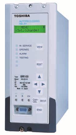
4 The front panel provides a 2x16 character, liquid crystal display (LCD) and 9 pushbutton keys to provide local access to the relay menu. There are also 6 light emitting diodes (LED) for visual indication of the status of the relay. The relay provides three communication ports, RS232C for connection of a local PC, RS485 for a remote PC and IRIG-B for an external clock. DC supply Voltage Binary input External clock DI/AI module -DC/DC converter -VT -Analog filter -A/D converter -Binary input -IRIG-B MPU module -MPU -LCD -LED -Operation key -RS232C I/F Human machine interface DO/COM module -Binary output (trip) -Binary output (signal) -RS485 Figure 3. Hardware block diagram Output Remote PC Local PC The terminal blocks are located at the rear of the relay providing connections for all input and output circuits. The relay is housed in the case as shown in Figure 6. METERING AND RECORDING Metering and Monitoring Voltages (V B, V L1, V L2 ) are measured continuously and displayed on the LCD on the relay fascia, at the local PC, and the remote PC when connected, and can be indicated as primary or secondary values. The user can monitor the following output and status on the LCD and at local/remote PCs Relay element output Binary input/output Event Record The most recent 96 time-tagged events are stored with 1 ms resolution. Events recorded are as follows. data can be stored for the 8 most recent faults. Fault record items are as follows. Date and time Trip phase Reclosing mode Pre-fault and post-fault voltage data Disturbance Record The relay can record 3 analogue signals (V B, V L1, V L2 ) and 11 binary signals. The disturbance recorder is initiated by a tripping and/or reclosing signal. Pre-fault recording time is fixed at 300ms, and post-fault recording time is user selectable from 100ms to 3s. The maximum number of stored records depends on the post-fault recording time. In the case of a post-fault recording time of 500 ms, up to 20 disturbance records can be stored. The number of the recorded data is displayed on the LCD. Calendar and Time A calendar and time are provided for time-tagging of recorded data. Synchronisation with the GPS (Global positioning system) is possible using the IRIG-B port. USER INTERFACE Relay Front Panel The relay front panel provides the following user interfaces. Setting the relay and viewing stored data are possible using the Liquid Crystal Display (LCD) and operation keys character, two line LCD with back light - 6 Light Emitting Diodes (LEDs) - Operation keys - RS232C port - Monitoring jacks Figure 4 shows the relay front panel. Reclosing Trip (Reclose initiation) signal Alarms Change of binary input signal Change of relay setting Relay failure Fault Record A trip signal initiates fault recording. Time-tagged fault Figure 4. Relay front panel 4
5 The following items are displayed on the LCD. - Setting - Metering - Event records - Fault records - The number of disturbance records - Any failure message detected by the automatic monitoring The RSM100 software is also used to communicate with the relay and to view or analyse disturbance records on the remote PC. Data transmission rate between relays and the protocol converter is 64kbps. Figure 5 shows the configuration of the RSM system. Password protection can be provided from the setting menu on the LCD to provide security for relay setting changes. After the password has been set, the password must be entered to access the setting menu from a local or remote PC as well as on the LCD. Details of metering, fault records, and relay failures can be monitored by pressing the VIEW key. The VIEW key can be pressed without removing the relay front cover. Arbitrary signals can be assigned to the two user configurable LEDs. Two monitoring jacks are operable when the test mode is selected in the LCD window. An oscilloscope can be connected to the relay through these jacks. Selection of output signals to the monitoring jacks can be set from the menu. Local PC The user can communicate with the GRR100 from a local PC via the RS232C port on the relay fascia. The following data can be viewed or analysed on the local PC with RSM100 software. - Setting - Metering - Event records - Fault records - Disturbance records Relay Setting and Monitoring (RSM) GRR100 can be connected to the RSM system via the RS485 interface at the rear of the relay. The user can operate the relay from a remote PC in the same way as from a local PC. A maximum of 32 x 8 relays can be connected to the remote PC in multi-drop mode, via the protocol converter G1PR2. The G1PR2 can be provided with maximum 8 ports and each port supports maximum 32 relays addressing. Figure 5. Relay setting and monitoring system IEC Communications GRR100-xxxB model supports the IEC communication protocol. This protocol is used for communication with a substation control and monitoring system and is used to transfer measurand data, status data and general commands, between the relay and the control system. Relay Setting The user can input or change settings using the operation keys on the relay fascia or via a local or remote PC with the RSM system. Password protection is provided to change settings. Four active setting groups are provided. This allows the user to set one group for normal operating conditions while other groups may be set to cover alternative operating conditions. Configurable Binary Output Contacts GRR100 is provided with 10 user configurable normally open output contacts for reclose command and alarm. Binary Inputs GRR100 is provided with 8 binary inputs for initiation of the GRR100, CB conditions and indication reset. The binary input circuit is provided with a logic level inversion function. 5


6 AUTOMATIC MONITORING PC DISPLAY Automatic Monitoring Function The automatic monitoring function will detect failures, should they occur, that might cause unwanted operation. The items monitored include the following: - Analogue-digital converter - Watchdog timer - DC power supply circuits - CPU Alarms Fault record In the unlikely event that a relay failure should occur, it will be detected by the automatic monitoring function and the LED ALARM on the relay fascia will be illuminated. A binary RELAY FAILURE output operates simultaneously and the date/time of any such failure will be stored in the event record. Event record Metering Setting 6
7 TECHNICAL DATA Ratings AC Voltage Frequency DC power supply AC ripple on DC supply IEC DC supply interruption IEC Permissive duration of DC supply voltage interruption to maintain normal operation Restart time Binary input circuit DC voltage Overload rating AC voltage input Burden AC voltage circuit DC power supply Binary input circuit Autoreclose setting Number of shots 1 to 4 Timer settings Dead time for single-phase autoreclose Dead time for three-phase autoreclose Multi-shot dead line time Multi-shot reset time Reclaim time Pulse width of reclosing signal output Autoreclose reset time Reset time for developing fault One-and-a-half breaker scheme Follower breaker autoreclose delay time Voltage and synchronism check element UV element (UVB, UVL) OV element (OVB, OVL) Synchronism check angle (SY) Busbar or line dead check (SYUVB, SYUVL) Busbar or line live check (SYOVB, SYOVL) Voltage difference check (SYDV) Frequency difference check (SYDf) Synchronism check time (TSYN) Voltage check time (TDBL, TLBD, TDBD) Operating time of synchronism check element Operating time of UV and OV element 100V, 110V, 115V, 120V 50Hz or 60Hz 110Vdc/125Vdc (Operative range: Vdc) 220Vdc/250Vdc (Operative range: Vdc) 48Vdc/54Vdc/60Vdc (Operative range: Vdc) maximum 12% maximum 50ms at 110Vdc less than 10s 110Vdc/125Vdc 220Vdc/250Vdc 48Vdc/54Vdc/60Vdc 1.4 times rated continuous 2 times rated for 1 second less than 0.1VA per phase less than 10W (quiescent) less than 15W(operation) less than 0.5W/input at 110Vdc 0.01 to 10.00s in 0.01 steps 0.01 to s in 0.01 steps 5.0 to 300.0s in 0.1s steps 5.0 to 300.0s in 0.1s steps 5 to 300s in 1s steps 0.1 to 10.0s in 0.1s steps 0.01 to s in 0.01 steps 0.01 to 10.00s in 0.01 steps 0.1 to 10.0s in 0.1s steps 10 to 150V in 1V steps 10 to 150V in 1V steps 5 to 75 in 1 steps 10 to 150V in 1V steps 10 to 150V in 1V steps 0 to 150V in 1V steps 0.01 to 2.00Hz in 0.01Hz steps 0.01 to 10.00s in 0.01s steps 0.01 to 10.00s in 0.01s steps less than 50ms less than 40ms 7
8 Communication port Front communication port (local PC) Connection Cable type Cable length Connector Rear communication port (remote PC) RS485 I/F Transmission data rate Connection Connector Cable and length Isolation Point to point Multi-core (straight) 15m (max.) RS232C 9-pin D-subminiature connector female 64kbps for RSM system 9.6kbps, 19.2kbps for IEC Multi-drop mode (max. 32 relays) Screw terminals Twisted pair cable with shield, max. 1200m 2kVac for 1min. IRIG-B port Connection Cable type Binary inputs Operating voltage Contact ratings Auxiliary contacts Make and carry Break Durability Make and carry Break Mechanical design Weight Case colour Installation BNC connector 50 ohm coaxial cable Typical 74Vdc(min. 70Vdc) for 110V/125Vdc rating Typical 138Vdc(min. 125Vdc) for 220V/250Vdc rating Typical 31Vdc(min. 28Vdc) for 48V/54V/60Vdc rating 4A continuously, 10A, 220Vdc for 0.5s (L/R5ms) 0.1A, 220Vdc (L/R=40ms) 10,000 operations minimum 100,000 operations minimum 5kg 2.5Y7.5/1(approximation to Munsell value) Flush mounting 8
9 ENVIRONMENTAL PERFORMANCE Test Standards Details Atmospheric Environment Temperature IEC /2 Operating range: -10C to +55C. Storage / Transit: -25C to +70C. Humidity IEC days at 40C and 93% relative humidity. Enclosure Protection IEC60529 IP51 (Rear: IP20) Mechanical Environment Vibration IEC Response - Class 1 Endurance - Class 1 Shock and Bump IEC Shock Response Class 1 Shock Withstand Class 1 Bump Class 1 Seismic IEC Class 1 Electrical Environment Dielectric Withstand IEC kVrms for 1 minute between all terminals and earth. 2kVrms for 1 minute between independent circuits. 1kVrms for 1 minute across normally open contacts. High Voltage Impulse IEC Three positive and three negative impulses of 5kV(peak), 1.2/50s, 0.5J between all terminals and between all terminals and earth. Electromagnetic Environment High Frequency Disturbance / Damped Oscillatory Wave Electrostatic Discharge Radiated RF Electromagnetic Disturbance Fast Transient Disturbance Surge Immunity Conducted RF Electromagnetic Disturbance Power Frequency Disturbance Conducted and Radiated Emissions IEC , IEC / EN IEC Class 3, IEC / EN IEC , IEC / EN IEC , IEC / EN IEC , IEC / EN European Commission Directives IEC , IEC / EN IEC Class A, IEC / EN IEC , IEC / EN CISPR22 Class A 89/336/EEC 73/23/EEC 1MHz 2.5kV applied to all ports in common mode. 1MHz 1.0kV applied to all ports in differential mode. 6kV contact discharge, 8kV air discharge. Field strength 10V/m for frequency sweeps of 80MHz to 1GHz and 1.4GHz to 2.7GHz. Additional spot tests at 80, 160, 450, 900, 1850, 2150MHz. 4kV, 2.5kHz, 5/50ns applied to all inputs. 1.2/50s surge in common/differential modes: HV ports: 2kV/1kV PSU and I/O ports: 2kV/1kV RS485 port: 1kV/0.5kV 10Vrms applied over frequency range 150kHz to 100MHz. Additional spot tests at 27 and 68MHz. 300V 50Hz for 10s applied to ports in common mode. 150V 50Hz for 10s applied to ports in differential mode. Not applicable to AC inputs. Conducted emissions: 0.15 to 0.50MHz: <79(peak) or <66(mean) db(v) 0.50 to 30MHz: <73(peak) or <60(mean) db(v) Radiated emissions (at 10m): 30 to 230MHz: <40dB 230 to 1000MHz: <47dB Compliance with the European Commission Electromagnetic Compatibility Directive is demonstrated according to EN and EN Compliance with the European Commission Low Voltage Directive is demonstrated according to EN and EN
10 PROTOCOL CONVERTER G1PR2 (OPTION) Ratings Power supply: 110Vdc/100Vac Operative range: Vdc of 110Vdc rated voltage Vac of 100Vac rated voltage 220Vdc/200Vac Operative range: Vdc of 220Vdc rated voltage Vac of 200Vac rated voltage 48Vdc Operative range: Vdc Burden: Communication port RS232C interface Connector type Cable type RS485 interface Connector Cable type Optical interface Operative Range: Wavelength: Connector type: Fibre type: IRIG-B Connector Mechanical design Enclosure Protection Weight Installation Atmospheric Environment Temperature Humidity less than 20W RS232C 9-pin D-subminiature connector female Multi-core (straight) Screw terminals (Phoenix Contact, FRONT type) Twisted pair cable less than 1.2km with 62.5/125m GI fibre (3dB/km) 820nm ST 62.5/125m glass fibre Screw terminals (Phoenix Contact, FRONT-MSTB type) IEC60529, IP20 5 kg Flush mounting IEC /2 IEC Operating range: -10C to +55C. Storage / Transit: -25C to +70C. 56 days at 40C and 93% relative humidity. 10
11 ORDERING 1. Autoreclose Relay (1) Single RS485 port G R R A 0 0 Relay Model Autoreclose for single breaker scheme 1 Autoreclose for two breaker scheme 2 Frequency 50Hz 1 60Hz 2 DC Power Supply Rating 110/125V 1 220/250V 2 48/54/60V 3 (2) Dual RS485 port (Available for IEC Communication) G R R B Relay Model Autoreclose for single breaker scheme 1 Autoreclose for two breaker scheme 2 Check Synchronising Phase Angle Difference 0 Phase Angle/Voltage/Frequency Difference 1 Rating 50Hz, 110/125Vdc 1 60Hz, 110/125Vdc 2 50Hz, 220/250Vdc 5 60Hz, 220/250Vdc 6 50Hz, 48/54/60Vdc A 60Hz, 48/54/60Vdc B 11
12 2. Protocol Converter (Option) G 1 P R 2 A 0 Model 1 port, Electrical signal (RS485) ports, Electrical signal (RS485) ports, Electrical signal (RS485) ports, Electrical signal (RS485): Max. 8, Optical signal: Max ports, Electrical signal (RS485): Max. 8, Optical signal: Max ports, Electrical signal (RS485): Max. 4, Optical signal: Max port, Electrical signal (RS485) or Optical signal port, Optical signal ports, Optical signal ports, Optical signal Power supply rating AC100/DC110V 1 0 AC200/DC220V 5 0 DC48V A 0 External time synchronisation None. 0 Provided. (IRIG-B) 1 12
13 RELAY OUTLINE IN SERVICE VIEW OPERATE ALARM TESTING RESET A B 0V CAN CEL ENTER END 104 Front view Side view 4 holes-5.5 TB2 TB CN1 E Rear view TB2 A1 B1 TB1 A1 B Panel cut-out A10 B10 TB1, TB2: M3.5 RING TERMINAL A18 B18 Terminal block Figure 6. Outline of GRR100 13
14 EXTERNAL CONNECTION DIAGRAM TB2 A1 A18 B18 Terminal Block Arrangement (Rear view) A1 A10 IRIG-B E TB1 B1 B10 () ()This connection is connected by short bar before shipment. Figure 7. Typical External connection for Model 1x1 14
15 A1 TB2 A1 A10 TB1 B1 B10 A18 B18 IRIG-B Terminal Block Arrangement (Rear view) E () ()This connection is connected by short bar before shipment. Figure 8. Typical External connection for Model 2x1 15
16 72-34, Horikawa-cho, Saiwai-ku, Kawasaki , Japan Tel Fax The data given in this catalog are subject to change without notice.
GRD130 - FEATURES APPLICATION
 FEATURES Phase undervoltage protection with IDMTL or DTL. Phase overvoltage protection with IDMTL or DTL. Zero phase sequence overvoltage (neutral voltage displacement) protection with IDMTL/DTL. Negative
GRT100 FEATURES APPLICATION
 FEATURES Fully numerical transformer protection Current differential protection for two-winding or three-winding transformers High-set differential overcurrent protection No interposing CTs required CT
INSTRUCTION MANUAL TRIP CIRCUIT SUPERVISION RELAY GKAD1
 INSTRUCTION MANUAL TRIP CIRCUIT SUPERVISION RELAY GKAD1 TOSHIBA Corporation 2004 All Rights Reserved. ( Ver. 1.6 ) Safety Precautions Before using this product, please read this chapter carefully. This
GRD110 FEATURES APPLICATION
 FEATURES Overcurrent protection for phase and earth faults with IDMTL or DTL. Three instantaneous elements with DTL. Programmable reset characteristics. Sensitive earth fault protection (SEF). Restricted
GRE130. Protection and Control for MV Systems
 Protection and Control for MV Systems FEATURES Phase undervoltage protection with IDMTL or DTL(27). Phase overvoltage protection with IDMTL or DTL(59). Zero phase sequence overvoltage (neutral voltage
Type MVTT 14 and MVTT 15: Static Digital Time delay relays
 Type MVTT 4 and MVTT 5: Static Digital Time delay relays Features 000/ setting range Time settings easily selected by means of thumbwheel switches Provide time delayed pick-up, or drop-off Compact construction
GRE120. Motor Protection and Control for MV Systems
 Motor Protection and Control for MV Systems FEATURES Overcurrent protection for phase and earth faults (50/51P, 50/51N). Dependent and independent time characteristics (IDMTL and DTL). Restricted earth
General catalog. Copyright 2017 Toshiba Energy Systems & Solutions Corporation. All rights reserved.
 General catalog 72-34, Horikawa-cho, Saiwai-ku, Kawasaki 212-8585, Japan Tel +81-44-331-1462 Fax +81-44-548-9540 http://www.toshiba-relays.com - The information provided in this catalog is subject to change
General catalog. Energy Systems & Solutions Company A2. Copyright 2017 Toshiba. All rights reserved.
 General catalog Energy Systems & Solutions Company 72-34, Horikawa-cho, Saiwai-ku, Kawasaki 212-8585, Japan Tel +81-44-331-1462 Fax +81-44-548-9540 http://www.toshiba-relays.com - The information provided
GRD150. FEATURES Protection functions. Control functions. Monitoring and Metering. Recording. User Interface APPLICATION
 FEATURES Protection functions Non-directional and directional overcurrent and earth-fault protection and sensitive earth fault protection (option) Overvoltage and undervoltage protection Thermal overload
Reyrolle Protection Devices. 7SG117 Argus 7 Synchronising Relay. Answers for energy
 Reyrolle Protection Devices 7SG117 Argus 7 Synchronising Relay Answers for energy 7SG117 Argus 7 Synchronising Relay Fig 1. Independent check & system synchronising settings Adjustable slip frequency,
Bus Bar Protection Relay B-PRO 4000
 Bus Bar Protection Relay B-PRO 4000 Product Overview The IEC 61850 station bus embedded B-PRO 4000 relay provides complete bus and substation differential protection (low impedance) with CT saturation
Relion 611 series. 611 series Type Test Certificate
 Relion 611 series 611 series Document ID: 1MRS757466 Issued: 2016-02-22 Revision: B Product version: 2.0 Copyright 2016 ABB. All rights reserved Table of contents Table of contents Section 1 Section
Type VRLTC tap changer
 Report No. 1ZUA938502-AGC 2, Rev 0 Date: 6 November 2012 Type VRLTC tap changer Ruggedized electronics systems specification & type test data Product Style No Rating By Type VRLTC, on-tank, vacuum reactance
Transformer Protection Relay
 Transformer Protection Relay T-PRO Product Overview The IEC 61850 station bus embedded T-PRO relay provides complete three-phase multi-winding transformer protection and overload protection, DFR-quality
GRE110. Protection and Control for MV Systems
 Protection and Control for MV Systems FEATURES Overcurrent protection for phase and earth faults (50/5P, 50/5N). Dependent and independent time characteristics (IDMTL and DTL). Four independent current
For Transmission, Distribution and Machinery protection.
 Founded in 1953, Microelettrica Scientifica has developed a wide range of products, divided into three main lines: For Transmission, Distribution and Machinery protection. A-Line Electronic analogic. M-Line
Sensitive Earth-fault Relay SPAJ 111 C. Product Guide
 Issued: April 1999 Status: Update Version: C/12.04.2006 Data subject to change without notice Features Sensitive low-set neutral overcurrent stage with definite time characteristic High-set neutral overcurrent
Earth-fault Relay SPAJ 110 C. Product Guide
 Issued: April 1999 Status: Updated Version: C/12.04.2006 Data subject to change without notice Features Low-set neutral overcurrent stage with definite time or inverse time characteristic High-set neutral
Combined Overcurrent and Earth-fault Relay SPAJ 140 C. Product Guide
 Combined Overcurrent and Earth-fault Product Guide Issued: April 1999 Status: Updated Version: C/18.04.2006 Data subject to change without notice Features Three-phase, low-set phase overcurrent unit with
General catalog AP. Copyright 2014 Toshiba. All rights reserved.
 General catalog 72-34, Horikawa-cho, Saiwai-ku Kawasaki-shi, Kanagawa 212-8585, Japan Tel +81-44-331-1462 Fax +81-44-548-9540 http://www.toshiba-relays.com - The information provided in this catalog is
MINER-S Station Controller
 MINER-S Station Controller Substation Automation MINER-S Station Controller The MINER-S Station Controller is a SCADA enabled fixed point remote terminal unit (RTU) with a data concentrator, event reporter,
Published by and copyright 2015 Siemens AG Energy Management Freyeslebenstr Erlangen, Germany
 Published by and copyright 2015 Siemens AG Energy Management Freyeslebenstr. 1 91058 Erlangen, Germany For more information, please contact our Customer Support Center Phone: +49 180/524 84 37 Fax: +49
Arc protection relay. Features Three-phase overcurrent function. Application
 Arc protection relay REA 10_ Page 1 Issued: May 1999 Status: New Data subject to change without notice Features Three-phase overcurrent function Loop-type or radial sensor fibre for arc detection Two high-speed
Protection and control. Sepam range Sepam 100 RT. Merlin Gerin Square D Telemecanique
 Protection and control epam range epam T Merlin Gerin quare D Telemecanique presentation contents page presentation connection characteristics installation ordering information epam T. on in in in in in
SIPROTEC easy 7SJ45 Numerical Overcurrent Protection Relay Powered by CTs
 SIPROTEC easy 7SJ4 Numerical Overcurrent Protection Relay Powered by CTs Function overview Fig. /1 Description The SIPROTEC easy 7SJ4 is a numerical overcurrent protection relay which is primarily intended
Voltage regulator. SPAU 341 C 1MRS MBG Issued: July 1998 Status: Revised Version: C/ Data subject to change without notice
 Issued: July 1998 Status: Revised Version: C/08.10.2003 Data subject to change without notice Features Comprehensive voltage regulation for power transformers with on-load tapchangers in distribution substations
BUSBAR. www. ElectricalPartManuals. com
 BUSBAR FATURS GR0 is a numerical low impedance differential relay for busbar protection. GR0 provides the following features. Discriminating zone and Check zone protection Maximum four zones Percentage
FL MC 2000E (SM40) LC
 LC") IEC 61850 fiber optic converter with LC fiber optic connection (1310 nm) to convert 100Base-Tx to single- or multi-mode fiber glass Data sheet 3205_en_C 1 Description PHOENIX CONTACT 2014-04-04 2 Features
IEC 61850 fiber optic converter with LC fiber optic connection (1310 nm) to convert 100Base-Tx to single- or multi-mode fiber glass Data sheet 3205_en_C 1 Description PHOENIX CONTACT 2014-04-04 2 Features
PROTECTION RELAYS THE ULTRA LINE NUMERICAL MULTIFUNCTION INTELLIGENT DEVICE FOR PROTECTION, SUPERVISION, METERING AND CONTROL
 MICROPROCESSOR PROTECTION RELAYS THE ULTRA LINE NUMERICAL MULTIFUNCTION INTELLIGENT DEVICE FOR PROTECTION, SUPERVISION, METERING AND CONTROL MICROELETTRICA SCIENTIFICA MANUFACTURES A COMPLETE RANGE OF
Scout-S Station Controller
 Scout-S Station Controller Substation Automation Scout-S Station Controller The Scout-S Station Controller is a SCADA enabled remote terminal unit (RTU) with a data concentrator, event reporter, and built-in
Feeder protection relay SPAA 121 C. Product Guide
 Issued: April 1999 Status: Updated Version: C/06.03.2006 Data subject to change without notice Features Two-phase low-set phase overcurrent unit with definite time or inverse time characteristic Two-phase
Feeder protection relay
 Page 1 Issued: April 1999 Status: New Data subject to change without notice Features Comprehensive numerical feeder protection relay consisting of two multi-function protection relay modules and a flexible
Feeder protection relay SPAA 341 C. Product Guide
 Issued: April 1999 Status: Updated Version: D/07.03.2006 Data subject to change without notice Features Comprehensive numerical feeder protection relay consisting of two multi-function protection relay
INGEPAC DA-CU. Control Unit. Data Sheet ZY8932IMA01E 31/03/2016
 ZY8932IMA01E 31/03/2016 INGEPAC DA-CU Control Unit Data Sheet Total or partial reproduction of this publication by any means or procedure is prohibited without previous express written authorisation by
TM3AI4 module TM3-4 analog inputs
 Characteristics module TM3-4 analog inputs Main Range of product Product or component type Range compatibility Analogue input number 4 Analogue input type Complementary Analogue input resolution Permissible
Residual overvoltage relay
 Page 1 Issued: April 1999 Status: New Data subject to change without notice Features Definite-time residual overvoltage earthfault protection and supervision Two independent operation stages, e.g. one
PowerLogic power-monitoring units. Power Meter PM500. Technical data sheet 2006
 PowerLogic power-monitoring units Technical data sheet 2006 Functions and characteristics E90463 The PowerLogic PM500 Power Meter provides all measurement capabilities required to monitor an electrical
GRE140. Protection and Control for MV Systems
 Protection and Control for MV Systems FEATURES Four stage non-directional and directional overcurrent protection for phase and earth faults with IDMTL or DTL. Polarizing voltage memory. Directional earth
7SG26 Tau Autoreclose and synchronization Answers for energy
 Reyrolle Protection Devices SG Tau Autoreclose and synchronization Answers for energy SG Tau Autoreclose and synchronization Fig 1. Tau relay in size 1 case Description The Tau range of auto-reclosing
SM100. On-Line Switchgear Condition Monitoring
 On-Line Switchgear Condition Monitoring On-Line Switchgear Condition Monitoring Introduction Weis is a specialist company with over 40 years of experience in the commissioning, testing & maintenance of
TM221M16R controller M IO relay
 Product data sheet Characteristics TM221M16R controller M221 16 IO relay Complementary Main Discrete I/O number 16 Number of I/O expansion module Supply voltage limits Inrush current Power consumption
TM3TM3 module TM3-2 temperature inputs and 1 analog output
 Characteristics module TM3-2 temperature inputs and 1 analog output Main Range of product Product or component type Range compatibility Analogue input number 2 Analogue input type Analogue output number
RE17LAMW on-delay timing relay - 1 s..100 h V AC/ DC - solid state output
 Characteristics on-delay timing relay - 1 s..100 h - 24..240 V AC/ DC - solid state output Main Range of product Product or component type Discrete output type Width Component name Time delay type Time
RE17LAMW on-delay timing relay - 1 s..100 h V AC/DC - solid state output
 Characteristics on-delay timing relay - 1 s..100 h - 24..240 V AC/DC - solid state output Complementary Control type Voltage range Main Range of product Product or component type Discrete output type Width
DRTS 66. The new generation of advanced test equipments for Relays, Energy meters, Transducers and Power quality meters
 The new generation of advanced test equipments for Relays, Energy meters, Transducers and Power quality meters Testing all relay technologies: electromechanical, solid state, numerical and IEC61850 Manual
Single-phase ( V) voltage monitoring: Undervoltage Overvoltage Window mode (overvoltage + undervoltage) Voltage fault memory selectable
 voltage monitoring: Undervoltage Overvoltage Window mode (overvoltage + undervoltage) Voltage fault memory selectable") 70 Series - Line monitoring relay 70 Features 70.11 70.31 70.41 Electronic voltage monitoring relays for single and three-phase applications Multifunctional types, providing the flexibility of monitoring
70 Series - Line monitoring relay 70 Features 70.11 70.31 70.41 Electronic voltage monitoring relays for single and three-phase applications Multifunctional types, providing the flexibility of monitoring
DRTS 3 PLUS Advanced Protection Relay Test Set and Measurement System
 Advanced Protection Relay Test Set and Measurement System Multi-tasking equipment designed for testing protection relays, energy meters, transducers Particularly designed to test RTU (remote terminal unit)
Energy Management Modular DC Energy analyzer Type VMU-E and VMU-X
 Energy Management Modular DC Energy analyzer Type VMU-E and VMU-X Modular solution based on the combination of two units: VMU-E analysis unit and VMU-X universal power supply and RS485 communication unit.
Communication Gateway COM 610. Product Guide
 Communication Gateway COM 610 Product Guide Issued: September 2004 Status: Updated Version: D/17.10.2006 Data subject to change without notice Features Protocol conversion gateway for substation automation:
RE22R1QMQ star-delta timing relay - 230VAC/440VAC - 1 C/O
 Characteristics star-delta timing relay - 230VAC/440VAC - 1 C/O Main Range of product Product or component type Discrete output type Device short name Nominal output current Complementary Contacts type
Relion 605 series. Self-powered feeder protection REJ603 Product Guide
 Relion 605 series Relion 605 series Relion 605 series Self-powered feeder protection Product Guide Product version: 3.0 Contents 1. Description... 3 2. Relay functions... 3 3. Protection functions... 4
Protection Relays PHASE & RESIDUAL OVERCURRENT
 Protection Relays PHASE & RESIDUAL OVERCURRENT Application The relay type NA016 can be used in radial networks as feeder or power transformer protection. In solidly grounded systems the residual overcurrent
TM3TI4 module TM3-4 inputs temperature
 Characteristics module TM3-4 inputs temperature Main Range of product Product or component type Range compatibility Analogue input number 4 Analogue input type Complementary Analogue input resolution Permissible
Characteristics. Application RTU560. DIN Rail RTU 560CIG10. Data Sheet DIN Rail RTU 560CIG10
 DIN Rail RTU 560CIG10 Application The 560CIG10 is a DIN rail RTU560 consisting of a communication unit (CMU), a multi-i/o module (MIO) and a power supply (PSU) in a metal DIN rail housing. The essential
RE17LCBM off-delay timing relay - control - 1 s..100 h V - solid state output
 Characteristics off-delay timing relay - control - 1 s..100 h - 24..240 V - solid state output Main Range of product Product or component type Discrete output type Width Component name Time delay type
Autodaptive Capacitor Control M 2501B
 CONTROLS Autodaptive Capacitor Control M 2501B Capacitor Control for Pole-Top Capacitor Banks Increases effectiveness of installed capacitors for voltage control to reduce system losses Adapts reference
Sensitive definite time or inverse time earth-fault stage for back-up residual earthfault
 Issued: April 1999 Status: Updated Version: B/09.11.2001 Data subject to change without notice Features Sensitive restricted earth-fault protection stage for fast, selective earth-fault protection Sensitive
DGSZV-EP DIGITAL GALVANIC LONGITUDINAL DIFFERENTIAL PROTECTION. Application field
 DGSZV-EP DIGITAL GALVANIC LONGITUDINAL DIFFERENTIAL PROTECTION The digital galvanic longitudinal differential protection of type DGSZV-EP is part of device family named EuroProt. This short description
Arc protection relay. Features Three-phase overcurrent function. Application
 Arc protection relay REA 10_ Issued: May 1999 Status: Updated Version: B/12.11.2001 Data subject to change without notice Features Three-phase overcurrent function Loop-type or radial sensor fibre for
Combined Overcurrent and Earth-fault Relay SPAJ 141 C. Product Guide
 Combined Overcurrent and Earth-fault Product Guide Issued: April 1999 Status: Updated Version: C/19.04.2006 Data subject to change without notice Features Three-phase, low-set phase overcurrent unit with
RT4B-110V/12A RECTIFIER
 The RT4B-110V/12A is a switched mode rectifier (SMR) module designed to provide up to 12A of output current into a 110V nominal system. It can be used with or without a cooling fan. With a fan it runs
Millenium 3. General Characteristics. General environment characteristics for CB, CD, XD, XR and XE product types
 Millenium 3 General Characteristics Millenium 3 Compact Range Millenium 3 Expandable Range Millenium 3 Communication Options Millenium 3 Range General environment characteristics for CB, CD, XD, XR and
MINER-S Station Controller. Substation Automation
 Substation Automation MINER-S Station Controller incorporates traditional RTU functions with new technology in a compact design MINER-S Station Controller combines the functions of a traditional RTU with
TM221M16TG controller M IO transistor PNP spring
 Characteristics controller M221 16 IO transistor PNP spring Main Range of product Product or component type [Us] rated supply voltage Discrete input number Analogue input number Discrete output type Discrete
Directional or Non-Directional Earth-Fault Relay REJ 527. Product Guide
 Directional or Non-Directional Earth-Fault Product Guide Issued: 17.06.19994 Status: Updated Version: C/16.10.2002 Data subject to change without notice Features Directional or non-directional low-set
GRE160. Transformer Protection
 Transformer Protection FEATURES Fully numerical transformer protection Current differential protection for two-winding transformers with inrush restraint (87T) High-set differential overcurrent protection
TM3TI8T module TM3-8 inputs temperature
 Characteristics module TM3-8 inputs temperature Main Range of product Product or component type Range compatibility Analogue input number 8 Analogue input type Complementary Analogue input resolution Input
RE48ATM12MW on-delay timing relay s..300 h V AC - 2 OC
 Characteristics on-delay timing relay - 0.02 s..300 h - 24..240 V AC - 2 OC Product availability : Stock - Normally stocked in distribution facility Price* : 73.00 USD Main Range of product Product or
Universal Power Supplies
 , Features Universal input: 90 264 VAC or 120 30 VDC Active power factor correction (>0.95) High efficiency up to 93% Load share function for up to 3 units in parallel Adjustable output voltage EMI/EMC
TU531, TU532 Terminal Unit
 Ordering Data DATA SHEET TU531, TU532 Terminal Unit 1 Ordering Data Part No. Description Product Life Cycle Phase *) 1SAP 217 200 R0001 1SAP 217 000 R0001 1SAP 417 000 R0001 TU531, terminal unit, 230 VAC,
DRTS 33. The new generation of advanced test equipments for Relays, Energy meters, Transducers and Power quality meters
 The new generation of advanced test equipments for Relays, Energy meters, Transducers and Power quality meters Testing all relay technologies: electromechanical, solid state, numerical and IEC61850 Manual
Appearance Size (mm) Power supply voltage Model (W H D) 100 to 240 VAC K3SC to 240 VAC
 Power supply voltage Model (W H D) 100 to 240 VAC K3SC to 240 VAC") Interface Converter A compact converter that allows communications between RS-C/USB and RS-/8 devices. Ideal for industrial applications. Allows communications between RS-C/USB (Universal Serial Bus) and
Interface Converter A compact converter that allows communications between RS-C/USB and RS-/8 devices. Ideal for industrial applications. Allows communications between RS-C/USB (Universal Serial Bus) and
extending the boundaries of technology evolution of proven technology FEATURES
 extending the boundaries of technology evolution of proven technology FEATURES IEC 61850 compliant Advanced AC capabilities with comprehensive fault detection Integrated protection functions Disturbance
Energy Management Modular DC Energy analyzer Type VIM-E and VIM-X
 Energy Management Modular DC Energy analyzer Type VIM-E and VIM-X Modular solution based on the combination of two units: VIM-E analysis unit and VIM-X universal power supply and RS485 communication unit.
RE48ATM12MW on-delay timing relay s..300 h V AC - 2 OC
 Characteristics on-delay timing relay - 0.02 s..300 h - 24..240 V AC - 2 OC Complementary Product front plate size Control type Housing material Main Range of product Product or component type Electrical
DRTS 33. The new generation of advanced three phase relay test set
 The new generation of advanced three phase relay test set Testing all relay technologies: electromechanical, solid state, numerical and IEC61850 Local control with color display Simultaneously available:
TM221CE24R controller M IO relay Ethernet
 Product data sheet Characteristics TM221CE24R controller M221 24 IO relay Ethernet Complementary Main Discrete I/O number 24 Number of I/O expansion module Supply voltage limits Network frequency Inrush
Output Voltage* (nom.)(adjustable)
(adjustable)") Industrial Power Supplies TBLC Series, 6 90 W Low profile case, module depth only 55 mm Suitable for mounting in domestic installation panels Very high efficiency and low standby power -> compliance to
Industrial Power Supplies TBLC Series, 6 90 W Low profile case, module depth only 55 mm Suitable for mounting in domestic installation panels Very high efficiency and low standby power -> compliance to
DRTS 3 PLUS. Advanced Protection Relay Test Set and Measurement System. DRTS 3 PLUS has been designed to test:
 Advanced Protection Relay Test Set and Measurement System Multi-tasking equipment designed for testing protection relays, energy meters, transducers Particularly designed to test RTU (remote terminal unit)
Relays for Various Protection Applications / 7SV600
 Relays for Various Protection Applications / SV00 SIPROTEC SV00 numerical circuit-breaker failure protection relay Fig. 0/ Description SIPROTEC SV00 numerical circuit-breaker failure protection relay The
TM221CE40R controller M IO relay Ethernet
 Characteristics controller M221 40 IO relay Ethernet Main Range of product Product or component type [Us] rated supply voltage Jan 6, 2019 Modicon M221 Logic controller 100...240 V AC Discrete input number
TF501, TF521 Terminal Bases
 Ordering Data DATA SHEET TF501, TF521 Terminal Bases 1 Ordering Data Part No. Scope of delivery Product life cycle status 1SAP 117 000 R0271 1SAP 317 000 R0271 1SAP 117 200 R0271 1SAP 317 200 R0271 TF501-CMS,
RE Product data sheet Characteristics. universal plug-in timing relay - flashing s..60 mn V AC - 2 OC. Main.
 Characteristics universal plug-in timing relay - flashing - 0.1 s..60 mn - 24..240 V AC - 2 OC Main Range of product Product or component type Discrete output type Contacts type and composition Width pitch
DC562, digital input/output module,
 Ordering Data DATA SHEET DC562 Digital Input/Output Module 1 Ordering Data Part No. Description Product Life Cycle Phase *) 1SAP 231 900 R0000 1TNE 968 901 R3101 1TNE 968 901 R3102 1TNE 968 901 R3103 1TNE
PDD-300 pulsed diode driver
 rev 1.08 / 2019 02 13 PDD-300 pulsed diode driver User manual Warning! This equipment may be dangerous. Please read user manual before starting operations. Important note. Please measure output with adequate
Part No. Description Product Life Cycle Phase *) unit, 24 VDC, spring terminals. unit, 24 VDC, spring terminals, XC version
 unit, 24 VDC, spring terminals. unit, 24 VDC, spring terminals, XC version") Ordering Data DATA SHEET TU520 Terminal Unit 1 Ordering Data Part No. Description Product Life Cycle Phase *) 1SAP 214 400 R0001 1SAP 414 400 R0001 TU520-ETH, PROFINET I/O terminal unit, 24 VDC, spring
Ordering Data DATA SHEET TU520 Terminal Unit 1 Ordering Data Part No. Description Product Life Cycle Phase *) 1SAP 214 400 R0001 1SAP 414 400 R0001 TU520-ETH, PROFINET I/O terminal unit, 24 VDC, spring
TM221CE40T controller M IO transistor PNP Ethernet
 Product data sheet Characteristics TM221CE40T controller M221 40 IO transistor PNP Ethernet Complementary Main Discrete I/O number 40 Number of I/O expansion module Supply voltage limits Inrush current
Reyrolle Protection Devices. 7SG118 Argus 8 Voltage & Frequency Relay. Answers for energy
 Reyrolle Protection Devices 7SG118 Argus 8 Voltage & Frequency Relay Answers for energy 7SG118 Argus 8 Voltage and Frequency Relay Data Storage and Communication Serial communications conform to IEC60870-5-103
RE11RAMU on-delay timing relay - 1 s..100 h V AC - 1 OC
 Characteristics on-delay timing relay - 1 s..100 h - 24..240 V AC - 1 OC Complementary Contacts material Width pitch dimension Control type Voltage range Connections - terminals Housing material Main Range
TM3TI4 module TM3-4 inputs temperature
 Characteristics module TM3-4 inputs temperature Complementary Analogue input resolution Permissible continuous overload Input impedance LSB value Conversion time Sampling duration Main Range of product
RE22R1QMQ star-delta timing relay - 230VAC/440VAC - 1 C/ O
 Characteristics star-delta timing relay - 230VAC/440VAC - 1 C/ O Main Range of product Product or component type Discrete output type Device short name Nominal output current Zelio Time Modular timing
Programmable Relay ZEN V2 Units
 Programmable Relay ZEN V2 Units Please read and understand this catalog before purchasing the products. Please consult your OMRON representative if you have any questions or comments. Refer to Warranty
RT4F-110V/25A RECTIFIER
 The RT4F-110V/25A is a hot-pluggable switched mode rectifier (SMR) module designed to provide up to 25A of output current into a 110V nominal system. Examples of such systems are 60 cells lead acid (136V
Synchro-check relay. Application
 Issued: April 1999 Status: Updated Version: B/08.11.2001 Data subject to change without notice Features Two identical operation stages allowing the closing conditions of two separate circuit breakers to
VCL-TP, Teleprotection Equipment With Trip Counter Display Panel
 VCL-TP, Teleprotection Equipment With Trip Counter Display Panel Data Sheet Copyright: Valiant Communications Limited. 2008-2014 1 Product Overview VCL-TP, Teleprotection Equipment is an extremely reliable
RT4F-120V/20A-WAC RECTIFIER
 The RT4F-120V/20A-WAC is a switched mode rectifier/charger module designed to provide up to 20A of output current into a 120V nominal system. This charger has been designed for use in conjunction with
www. ElectricalPartManuals. com SYNCHROTACT 5 SYN 5100 SYN 520X SYN 5302 Communications interfaces for remote servicing via the internet
 New! Document No. SYNCHROTACT 5 Synchronizing and paralleling devices and systems SYN 500 SYN 50X SYN 530 Description ABB Industrie AG is a world-leading manufacture of synchronization equipment. Applicationoriented
DRTS 64. The new generation of advanced test equipment for Relays, Energy meters, Transducers and Power quality meters.
 The new generation of advanced test equipment for Relays, Energy meters, Transducers and Power quality meters Testing all relay technologies: electromechanical, solid state, numerical and IEC61850 Manual
Feeder Protection Relay REF 610. Product Guide
 Product Guide Contents 1 Description.............................. 3 2 Protection functions....................... 3 3 Measurement............................ 4 4 Disturbance recorder......................