KVM over IP Console Station KA8270 / KA8278 / KA8280 / KA8288 User Manual.
|
|
|
- Norman Davis
- 5 years ago
- Views:
Transcription


1 KVM over IP Console Station KA8270 / KA8278 / KA8280 / KA8288 User Manual

2 EMC Information FEDERAL COMMUNICATIONS COMMISSION INTERFERENCE STATEMENT: This equipment has been tested and found to comply with the limits for a Class A digital device, pursuant to Part 15 of the FCC Rules. These limits are designed to provide reasonable protection against harmful interference when the equipment is operated in a commercial environment. This equipment generates, uses, and can radiate radio frequency energy and, if not installed and used in accordance with the instruction manual, may cause harmful interference to radio communications. Operation of this equipment in a residential area is likely to cause harmful interference in which case the user will be required to correct the interference at his own expense. The device complies with Part 15 of the FCC Rules. Operation is subject to the following two conditions: (1) this device may not cause harmful interference, and (2) this device must accept any interference received, including interference that may cause undesired operation. FCC Caution: Any changes or modifications not expressly approved by the party responsible for compliance could void the user's authority to operate this equipment. Warning: Operation of this equipment in a residential environment could cause radio interference. KCC Statement 이기기는업무용 (A 급 ) 전자파적합기기로서판매자또는사용자는이점을주의하시기바라며, 가정외의지역에서사용하는것을목적으로합니다. RoHS This product is RoHS compliant. ii
3 User Information Online Registration Be sure to register your product at our online support center: International Telephone Support For telephone support, call this number: International China Japan Korea North America ATEN ext User Notice All information, documentation, and specifications contained in this manual are subject to change without prior notification by the manufacturer. The manufacturer makes no representations or warranties, either expressed or implied, with respect to the contents hereof and specifically disclaims any warranties as to merchantability or fitness for any particular purpose. Any of the manufacturer's software described in this manual is sold or licensed as is. Should the programs prove defective following their purchase, the buyer (and not the manufacturer, its distributor, or its dealer), assumes the entire cost of all necessary servicing, repair and any incidental or consequential damages resulting from any defect in the software. The manufacturer of this system is not responsible for any radio and/or TV interference caused by unauthorized modifications to this device. It is the responsibility of the user to correct such interference. The manufacturer is not responsible for any damage incurred in the operation of this system if the correct operational voltage setting was not selected prior to operation. PLEASE VERIFY THAT THE VOLTAGE SETTING IS CORRECT BEFORE USE. iii
4 Package Contents 1 KVM over IP Console Station (KA8270 or KA8278 or KA8280 or KA8288) 1 Power Adapter 1 Power Cord 1 Mounting Kit 1 Foot Pad Set (4 pcs.) 1 User Instructions* * Features may have been added to the KVM over IP console station since the user instructions were created. Please visit our website to download the most up-to-date version of the user manual. Check to make sure that all of the components are present and in good order. If anything is missing, or was damaged in shipping, contact your dealer. Read this manual thoroughly and follow the installation and operation procedures carefully to prevent any damage to the KVM over IP console station or to any other devices on the installation. Copyright 2018 ATEN International Co., Ltd. Manual Date: Altusen and the ATEN logo are registered trademarks of ATEN International Co., Ltd. All rights reserved. All other brand names and trademarks are the registered property of their respective owners. iv
5 Contents EMC Information ii User Information iii Online Registration iii Telephone Support iii User Notice iii Package Contents iv Contents v About This Manual viii Conventions ix Product Information ix Chapter 1.Introduction Overview Features Requirements Console Components Front View Rear View Chapter 2.Hardware Setup Overview Before You Begin Mounting Rack Mounting Wall Mounting Single Stage Installation Hot Plugging Powering Off and Restarting Chapter 3.Operation Overview Logging In Dashboard Page Components Dashboard Operation Monitor Unit Option Primary / Secondary Display GUI Disconnect Reconnect Tab / Panel Array Display and Management Tab Options Tab Display Panel Array Options v
6 Panel Array Display Tab / Panel Array Management Adding a Tab Adding another Tab Editing a Tab Deleting a Tab Chapter 4.Device Management Overview Device List Search Remove Device Adding Device Changing Device Access Right Chapter 5.System Configuration Overview User Management Users and Groups Add User Copy User Modify User Delete User Managing (Assigning) Users and Groups Using User Configuration Page Using Group Configuration Page Device Assignment Using Device Configuration Page Device Management Device Information Network IP Installer IPv4 Settings IPv6 Settings Finishing Up ANMS RADIUS Settings AD / LDAP Settings Finishing Up Security Login Failures Account Policy Working Mode Finishing Up Maintenance Upgrade Main Firmware Firmware Upgrade Recovery vi
7 Backup / Restore Backup Restore Push / Pull Configuration Pull Configuration Push Configuration Terminal System Operation Reset Default Values Reset on exit: Quick User Configuration Chapter 6.Toolbar Interface Overview Exit Remote Location Video Settings Macros Hotkeys User Macros Import / Export Macros Delete Macros Search Macros System Macros Further Configuration Virtual Media Message Board Mouse Sync Mode Appendix Safety Instructions General Rack Mounting Consignes de sécurité Général Montage sur bâti Technical Support International North America Specifications Troubleshooting General Operation Mouse Problems Virtual Media Panel Array Mode Supported KVM Switches Limited Warranty vii
8 About This Manual This User Manual is provided to help you get the most from your KVM over IP Console Station. It covers all aspects of installation, configuration and operation. An overview of the information found in the manual is provided below. Chapter 1, Introduction, introduces you to the KVM over IP Console Station. Its purpose, features and benefits are presented, and its front and back panel components are described. Chapter 2, Hardware Setup, provides step-by-step instructions for setting up your installation, and explains some basic operation procedures. Chapter 3, Operation, explains the fundamental concepts involved in operating the product, and provides a complete description of how to operate the product. Chapter 4, Device Management, explains how to add or remove KVM over IP switches to or from the product. Chapter 5, System Configuration, explains the system settings, which include the General, ANMS, AD/LDAP, RADIUS, F/W Upgrade, Backup/Restore, and explains the quick user interface. Chapter 6, Toolbar Interface, explains how to use the toolbar interface when entering a connected port. An Appendix, at the end of the manual provides technical and troubleshooting information. viii
9 Conventions This manual uses the following conventions: Monospaced Indicates text that you should key in. [ ] Indicates keys you should press. For example, [Enter] means to press the Enter key. If keys need to be chorded, they appear together in the same bracket with a plus sign between them: [Ctrl+Alt]. 1. Numbered lists represent procedures with sequential steps. Bullet lists provide information, but do not involve sequential steps. Indicates selecting the option (on a menu or dialog box, for example), that comes next. For example, Start Run means to open the Start menu, and then select Run. Indicates critical information. Product Information For information about all ATEN products and how they can help you connect without limits, visit ATEN on the Web or contact an ATEN Authorized Reseller. Visit ATEN on the Web for a list of locations and telephone numbers: International North America ix
10 This Page Intentionally Left Blank x
11 Chapter 1. Introduction Chapter 1 Introduction Overview The KVM over IP Console Station (KA8270/KA8278/KA8280/KA8288) is a standalone console that replaces PC or NB, enabling users to remotely access, monitor and control all servers connected to multiple ATEN s KVM over IP switches* with impenetrable security against virus threats. It also supports various data encryption methods, ensuring impervious data protection. The KVM over IP Console Station can be deployed anywhere instant access is needed and stringent security required, ideal for applications such as studios, offices, data centers, broadcast stations, control rooms, or network operations centers (NOC). All the KA8270, KA8278, KA8280, and KA8288 support USB mouse/ keyboard and two USB ports for Virtual Media function, and respectively support 1 VGA video output, 1 VGA plus 1 HDMI video outputs, 1 HDMI video output, and 2 HDMI video outputs at resolutions up to 1920 x 60 Hz. With KA8278 and KA8288, users can multitask across two displays with a single keyboard and mouse. In addition, the KVM over IP Console Station provides Panel Array Mode function, enabling administrators to monitor the video output of up to 64 servers simultaneously. The feature makes it possible for previewing the content of all the ports at the same time, which is especially suitable for environments such as manufacturing and surveillance that often require monitoring of a much higher number of ports. The KVM over IP Console Station can be set on a desk, mounted on a wall or at the rear of a rack with its space-saving 0U rack mount design. It is flexible and easy to install, and provides a GUI with multi-language interface for device management, user profile customization, as well as hassle-free configuration for large deployments. * Compatible KVM over IP switches include KN1132V, KN2116VA, KN4116VA, KN2132VA, KN4132VA, KN4164V, KN8132V, KN8164V, KN2124VA, KN4124VA, KN2140VA, and KN4140VA. The aforementioned KVM over IP 1
12 switches require firmware version v or above to support the KVM over IP Console Station. Features A standalone console that replaces PC or NB, enabling users to remotely access and control ATEN s KVM over IP switches Impenetrable security against virus threats and impervious data protection Single sign-on to consolidate the management of multiple ATEN s KVM over IP switches Advanced FPGA graphics processor with a Full HD resolution of 1920 x 1200 Supports 1 VGA video output (KA8270) or 1 HDMI video output (KA8280) Supports 1 VGA plus 1 HDMI video outputs (KA8278) or 2 HDMI video outputs (KA8288) enables users to multitask across two displays with a single keyboard and mouse Panel Array Mode allows administrators to monitor the video output of up to 64 servers on one screen simultaneously Supports Virtual Media Wall Mountable standard rack mount kit included Space-saving 0U rack mount design with rear mounting GUI with multi-language interface provides easy access and management, user profile customization, and flexible configuration for large deployments Requirements Console A VGA monitor (KA8270); an HDMI monitor(ka8280 or KA8288); a VGA or HDMI monitor (KA8278) A USB mouse A USB keyboard Microphone and Speakers 2
 3 USB Ports (Keyboard and Mouse) 4 Audio Ports 5 Cascade Port 6 Power Push Button (Press to")
13 Chapter 1. Introduction Components Front View No. Component 1 Reset Switch 2 USB Ports (Peripherals) 3 USB Ports (Keyboard and Mouse) 4 Audio Ports 5 Cascade Port 6 Power Push Button (Press to enter the standby mode; press again to wake the unit) 7 Power LED (Power on: Blue; Standby: Orange) 3

14 Rear View No. Component 1 Grounding Terminal 2 Power Jack 3 LAN Port 4 COM Port 5 VGA Port (KA8270 and KA8278 only) 6 HDMI Port(s) (KA8278, KA8280 and KA8288 only) 4
15 Chapter 2. Hardware Setup Chapter 2 Hardware Setup Overview This chapter outlines different ways of mounting your KVM over IP Console Station as well as a quick hardware connection summary in the form of single stage installation. Before You Begin 1. Important safety information regarding the placement and grounding of this device is provided on page 81 and onwards. Please review it before proceeding. 2. Make sure that power to all the devices you will be connecting up have been turned off. You must unplug the power cords of any computers that have the Keyboard Power On function. 5
16 Mounting The KVM over IP Console Station can be rack mounted or wall mounted. The following sections take you through the procedures for each method. Rack Mounting The KVM over IP Console Station is designed to be mounted at the rear of a rack, where it occupies 0U to save space. 1. Remove two bottom screws of the unit and use those to screw the mounting bracket to the bottom of the unit as shown in the diagram below: 2. Screw the mounting bracket to any convenient location on the rack. Note: Rack screws are not provided to mount the unit. We recommend that you use M5 x 12 Phillips type I cross screws. 6
17 Chapter 2. Hardware Setup Wall Mounting 1. Remove two bottom screws of the unit and use those to screw the mounting bracket to the bottom of the unit as shown in the diagram below: 2. Use the mounting bracket s center screw hole to mount the unit on a wall. 7
18 Single Stage Installation For a single stage installation, refer to the installation diagram and procedures shown below (KA8278 is used as an example): Note: The numbers shown in the diagram are the installation steps corresponding directly to the steps below. 1. Plug the connectors of your USB mouse, USB keyboard, microphone, and speakers into their respective ports on the front panel of the KVM over IP Console Station. Each port is color coded and marked with an icon. 2. Plug the monitor into the VGA or the HDMI port on the rear panel of the KVM over IP Console Station. Note: 1. KA8270 supports 1 VGA video output, KA8278 supports 1 VGA and 1 HDMI video outputs, KA8280 supports 1 HDMI video output, and KA8288 supports 2 HDMI video outputs. 2. For models that support two video outputs (KA8278 and KA8288), the video interface at the inner side (e.g., the VGA video interface of KA8278) is the Primary Display, the video interface at the outer side is the Secondary Display. 3. Login page will appear on Primary Display and make sure you use the Primary Display to log in. 3. Plug an Ethernet cable from the LAN into the KVM over IP Console Station s LAN port. 4. (Optional) Plug USB drives into the dedicated USB ports located on the front panel. 5. (Optional) To cascade one more unit, plug one end of a Cat 5e cable into the Cascade port on the front panel, and then plug the other end of the cable to the LAN port of another KVM over IP Console Station. The added unit will gain the first unit s Internet connection. Configuration / control of each unit is separate. Note: Do not connect the Cascade Port to a network switch or it will cause a switching loop. 8
19 Chapter 2. Hardware Setup 6. (Optional) Use a grounding wire to connect the Grounding Terminal on the rear panel of the KVM over IP Console Station to a suitable grounded object. 7. Plug the power adapter into an AC source with the power cord; then plug the other end into the KVM over IP Console Station s Power Jack. Hot Plugging KVM over IP console stations support hot plugging components can be removed and added back into the installation by unplugging and replugging cables from the ports without the need to shut the unit down. 9
20 Powering Off and Restarting If it becomes necessary to power off the console station, please use the shut down function (see Shutdown on page 62), disconnect the power adapter and wait 30 seconds before reconnecting it back. 10
21 Chapter 3. Operation Chapter 3 Operation Overview The KVM over IP console station can be used as a central control station to monitor several KVM switches. Available interfaces are described in the sections that follow. Logging In The KVM over IP Console Station can be used as a central control station to monitor several KVM switches. A valid Username and Password are required to login. If you supply invalid login information, the authentication routine will return an Invalid Username or Password, or Login Failed message. If you see this type of message, log in again with a correct username and password. Note: If the number of invalid login attempts exceeds a specified amount, a timeout period is invoked. You must wait until the timeout period expires before you can attempt to log in again. See Login Failures on page 48 for further details. The login screen is shown below: 11
22 The KVM over IP console station supports two modes: a) KVM over IP console station mode: Logging into the console station (My Device). b) KVM device mode: Logging into a KVM device directly. Follow the steps below to log in: 1. If you wish to log into a KVM device directly, specify the device s IP Address and its Port. For the KVM over IP console station login, select My Device from the drop down menu for the Address field and go to the next step. Note: 1. As an alternative, you can drag your mouse over the magnifying glass symbol to find the addresses of the devices on the same local area network; or 2. Click the drop-down menu for a device list. The device list shows the device login history. My Device is always shown at the top of the list. The history can be cleared using a terminal command, please see Terminal on page Enter a Username and Password (by default Username and Password are administrator and password, respectively) and click Login to log in. Note: For security purposes, you should change the Username and Password. (See Users and Groups on page 30) 3. (Optional) At the bottom right-hand corner, a language option is available (English is shown as it is the default language). Click it to select a preferred language for the interface. After you successfully login, the dashboard of the console station will appear. Please refer to Dashboard on page 13 for the operations. 12

23 Chapter 3. Operation Dashboard Once you have successfully logged in, the KVM over IP console station s user interface dashboard appears: Note: The screen depicts an Administrator s page. Depends on the user s type and permissions, not all of these elements will appear. Page Components The page components of the dashboard are described in the table below: No. Item Description 1 Tab Management 2 Panel Array Management 3 Device Management Tab management allows users to separate KVM over IP switches currently being monitored into different tab groups or select which tab is to be displayed. Panel array management allows users to simultaneously display the ports connected to the KVM over IP switches. The ports can also be grouped into different groups and only simultaneously display the ports in the chosen group. Device management allows users with administrative authority to add devices to or remove devices from the console station. 13
24 No. Item Description 4 System Configuration System configuration allows users with administrative authority to manage users or groups, display device information, configure network, advanced network management (ANMS) or security settings, or manage firmware upgrade, system backup / restore, push / pull configurations to or from other devices, access terminal, or reset system to factory default settings. 5 User Settings User settings allow users to change password, configure preferences, logout, restart the system, shut down the system, or display quick information about the console station. 6 Username This displays the username. 7 Individual Monitor Option 8 Available KVM over IP Switch Monitor Individual monitor option allows users to select which port is to be displayed on an assigned display, open the GUI or disconnect from the KVM over IP switch. If the switch is disconnected, you can also click Reconnect to reconnect the switch to the console station. For example, if you have a primary and secondary display (KA8278 or KA8288), you can choose to display one of the ports on the primary display while another port on the secondary display. See Primary / Secondary Display on page 16. Available KVM over IP switch monitor displays the available KVM over IP switch at a glance. Each monitor will consecutively rotate through the device s connected ports. 9 Tab name This displays the tab name. Clicking the tab name will bring out an option Reconnect All Devices. Click the option for the reconnect operation. 14

25 Chapter 3. Operation Dashboard Operation The dashboard of the console station usually displays the connected devices in an array of monitor units. Each of the unit corresponds to a connected device. The unit will rotate consecutively between all the connected ports. Double-clicking a monitor will bring you to the port s page. For individual monitor options of a particular device, move your mouse over its corresponding monitor unit. A menu icon will be shown on the top right-hand corner of each unit. = Menu icon 15
, the menu may show a Primary Display option or both a Primary Display option and a Secondary Display option.")

26 Monitor Unit Option Clicking the Menu icon to display available options: Primary / Secondary Display Depends on your console station model (whether you have one or two display ports), the menu may show a Primary Display option or both a Primary Display option and a Secondary Display option. To display a port on a primary or secondary display: 1. Mouse over the display (primary or secondary): 2. Click to select the port. The selected display should now show the port s screen. Your keyboard and mouse can now also control the server connected to the port. For the control of the server, the KVM over IP console station s 16
27 Chapter 3. Operation interface provides a toolbar to help you with the remote control operations. Please refer to Toolbar Interface on page 63. GUI If you wish to use the KVM over IP switch s GUI, click to select Open GUI. Please refer to the KVM switch s user manual for the GUI s operation. Disconnect Click Disconnect to disconnect from this KVM switch device. Reconnect Click Reconnect to reconnect to an offline KVM switch device. 17

28 Tab / Panel Array Display and Management Tab management allows users to separate KVM over IP switches currently being monitored into different groups or select which tab group is to be displayed on the dashboard. Panel array management allows users to separate available ports into different groups or select which panel array group is to be displayed on the panel array page. Tab Options Click the Tab icon to display the tab options. Option Tab Management All Devices Created tabs Description Click this option to allow you to add, delete or modify tabs (groups). Click this option to display all the connected KVM over IP switches on the dashboard. Select a created tab to display the KVM over IP switches in the tab on the dashboard. 18
: Panel Array Options Click")
. All the ports connected KVM over IP switches are displayed on the panel array page.")
29 Chapter 3. Operation Tab Display An example showing the KVM over IP switches in a tab displayed on the dashboard (tab1 is the selected tab): Panel Array Options Click the Panel Array icon to display the panel array options: Option Panel Array Management All Devices Created panel arrays Description This option allows you to add, delete or modify panel array (groups). All the ports connected KVM over IP switches are displayed on the panel array page. Select a created panel array. All the ports connected to the KVM over IP switches in the panel array are displayed on the panel array page. Note: Audio is not supported. 19
30 Panel Array Display An example showing the ports of connected KVM over IP switches in a panel array displayed (array1 selected): Press the + icon to display more device ports (up to 64 ports) on a smaller scale. Press the - icon to display less device ports on a larger scale. The diagram below displays a view on a smaller scale. 20

31 Chapter 3. Operation The panel array icon is also shown on the top right-hand corner of the panel array page. Clicking it will allow you to select which array you would like to display, or display all device ports: Click the back arrow to go back to the dashboard. Tab / Panel Array Management Click the Tab or Panel Array icon to show their corresponding options. Due to their similarity, tab management is used as the example below. Click Tab Management (or Panel Array Management ) for the following page: This page allows you to add / edit / delete tabs. 21

32 Adding a Tab 1. To add a tab, click the + icon. A new window (Tab Device Configuration) will be displayed: 2. Enter a name for the new tab. 3. Click on the devices you wish to be in this tab group and click the >> button. 4. Click the OK button when done. The tab will be shown: 22
33 Chapter 3. Operation Adding another Tab If you wish to add another tab, click the + icon again and go through the steps outlined in Adding a Tab. 23
34 Editing a Tab If you wish to edit a tab, click the pen icon beside the Tab Name. The Tab Device Configuration window will be displayed as in Adding a Tab. Edit its name, shift the devices around using the >> or << icons and click OK when done. Deleting a Tab If you wish to delete a tab, click the X icon beside the Tab Name. 24
35 Chapter 4. Device Management Chapter 4 Device Management Overview Device management allows users with administrative authority to add devices to or remove devices from the console station. The KVM over IP console station can manage up to 256 KVM over IP switches and able to display snapshots of up to 16 devices. Click on the Device Management icon to enter its main page. 25
36 Device List The feature on the left of the Device Management page is the device list. Search The rectangular field at the top is the search function. Enter the IP address of the device you wish to search for to find that device. Remove Device If you wish to remove a device from the list, mouse over the device. A X icon will be displayed as shown below: Click the X icon to remove the device. The system will ask for confirmation as shown below: 26
.")
37 Chapter 4. Device Management Click Yes to go ahead, or No to cancel action. Adding Device The feature in the middle of the Device Management page allows the user to add devices to the system. Mouse over the search button (magnifying glass). A list of KVM control unit device(s) on the same local area network (LAN) will be shown as exemplified below: Select the desired device or simply enter an IP Address of a known device; enter a Username and Password, and click Save to add the device to the system. Note: 1. The entered username and password will determine the access rights of the KVM over IP Console Station. 2. If you wish to gain full access right of the KVM switch device, please use the username and password of a user with full access right. 27

38 3. If you select the desired device by clicking the Device Name or IP Address sections, the displayed name will show the IPv4 Address. Instead, IPv6 Address will be displayed when clicking the IPv6 Address section.. 4. If a KVM over IP Switch is also added to CC2000 and has Disable Other Authentication configured in CC2000, the KVM over IP Console Station will not be able to access / control that switch. Click Reset if you wish to re-enter the information. The system will attempt to connect to the device. If successful, the device will be listed in the device list. Changing Connection Information If you wish to change the access right of a device connected to the KVM over IP Console Station, you will need to change to a user with the desired access right. Follow the steps below: 1. Select the device from the device list. 2. Edit the settings in the Device Information section: 3. Click Save to update the information. 4. Log out of the KVM over IP Console Station and log in again to see the updated settings / display / access right. 28
39 Chapter 5. System Configuration Chapter 5 System Configuration Overview System configuration allows users with administrative authority to manage users or groups, display device information, configure network, advanced network management (ANMS) or security settings, or manage firmware upgrade, system backup / restore, push / pull configurations to or from other devices, access terminal, or reset system to factory default settings. Click on the System Configuration icon to enter its main page. The page is consisted of a left-hand side menu and a right-hand side information / configuration body. By default, device information is displayed upon entering system configuration page as shown above. If an item in the side menu has a + or - symbol, a submenu is available when expanded. Expand the submenu by clicking the + symbol. Collapse the submenu by clicking the - symbol. 29
40 User Management This section allows you to manage users and groups. Users and Groups Groups allow administrators to easily and efficiently manage users and devices. Since device access rights apply to anyone who is a member of the group, administrators need only set them once for the group, instead of having to set them for each user individually. Multiple groups can be defined to allow some users access to specific devices, while restricting other users from accessing them. The KVM over IP console station supports two privilege categories determined by User Types. User types are selected during user creation. The description is shown in the table below: User Types Administrator User Role Access and manage devices. Manage Users and Groups. Configure the overall installation. Configure personal working environment. Access authorized devices. Configure personal working environment. Click Users or Groups under User Management in the left-hand side menu to bring out their respective configuration page. User Page 30

41 Chapter 5. System Configuration Group Page Add User Since the management of users and groups are very similar, User is the example used for the operations below. To add a user: 1. Click Add User on the top right-hand corner of the page. The following will be displayed: 2. Enter the required information in the appropriate fields. A description of the required user fields are given in the table below: Field Username Password Description 1 to 32 characters are allowed depending on the Account Policy settings. See Account Policy on page to 32 characters are allowed depending on the Account Policy settings. See Account Policy on page
42 Confirm Password Description Role Status Field Description To make sure there is no mistake in the password, please enter it again. The two entries must match. Additional information about the user that you may wish to include. There are two categories: Administrator and User. There is no limitation on the number of accounts that can be created in each category. The Administrator is responsible for the overall installation configuration and maintenance; user management; and device assignments. Each user assigned to administrator role will have the privilege of adding KVM over IP switches by default. Please refer to Using User Configuration Page on page 35. Status allows you to control the user s account and access to the installation, as follows: Disable Account lets you suspend a user s account without actually deleting it, so that it can be easily reinstated in the future. To require a user to change his password at the next logon, select User must change password at next logon. This can be used by the administrator to give the user a temporary password to log in for the first time, and then let the user set the password of his choice for future logins. To make a password permanent, so that the user cannot change it to something else, select User cannot change password. If you choose Groups in the left-hand side menu, click Add Group for the page below: A description of the required fields are given in the table below: Field Group Name Description Up to 32 characters are allowed. Description Additional information about the user that you may wish to include. A maximum of 45 characters is allowed. 32
43 Chapter 5. System Configuration 3. You can assign the new user to a group by selecting the Groups tab the Groups page is discussed on page 36. You can also assign the user s port access rights by selecting the Devices tab the Devices page is discussed on page 39. Note: Optionally, you can skip this step now to add more users and create groups, and come back to it later. 4. When your selections have been made click Save. 5. When the Operation Succeeded message appears, click OK. Click Back on the top right-hand corner of the configuration body or click Users in the left-hand side menu to return to the User Management page. The newly added user will appear in the configuration body. The information / configuration body shows the username, the description that was given when the account was created, whether the account is currently active or has been disabled and give you the option to modify or delete the user. Copy User To save time creating a user with similar settings / information, you may use the Copy User function. A Copy User button is shown on the top right-hand corner of the configuration body. Select the user you wish to copy and click the Copy User button; follow the information in Add User to complete the configuration. 33
44 Modify User If you wish to modify the user s information, click the pen icon under the Modify column of the information / configuration body. For configurable fields, please refer to Add User above. Delete User If you wish to delete a user, click the X icon under the Delete column of the information / configuration body. The system will ask for confirmation as shown below: Click Yes to go ahead, or No to cancel action. 34

45 Chapter 5. System Configuration Managing (Assigning) Users and Groups There are two ways to assign users to groups: from the Users configuration page; and from the Group configuration page. Note: Before you can assign users to groups, you must first create them. See Add User on page 31 for details. Using User Configuration Page Follow the steps below to go to the User s configuration page: 1. Click Users under User Management in the left-hand side menu to bring out the configuration page. 2. Click the pen icon under the Modify column. 3. In the configuration page, select the Groups tab as shown: Assign a User to a Group 1. In the Available column, select the group that you want the user to be in. 2. Click the >> icon button to put the group s name into the Selected column to add the user to group. 35

46 3. Repeat the above for any other groups that you want the user to be in. 4. Click Save when you are done. Remove Users from a Group 1. In the Selected column, select the group that you want the user to be removed from. 2. Click the << icon button to remove the group s name from the Selected column to remove the user from the group. 3. Repeat the above for any other groups that you want the user to be removed from. 4. Click Save when you are done. Using Group Configuration Page Follow the steps below to go to the Group s configuration page: 1. Click Groups under User Management in the left-hand side menu to bring out the configuration page. 2. Click the pen icon under the Modify column. 3. In the configuration page, select the Members tab as shown: 36
47 Chapter 5. System Configuration Assign Users to a Group 1. In the Available column, select the members (users) that you want the group to have. 2. Click the >> icon button to put the members into the Selected column (thereby adding into the group). 3. Repeat the above to assign members to each group. 4. Click Save when you are done. Remove Users from a Group 1. In the Selected column, select the members (users) to be removed from the group. 2. Click the << icon button to put the members into the Available column (thereby removing from the group). 3. Repeat the above to remove members from each group. 4. Click Save when you are done. 37

48 Device Assignment This function assigns access rights to users or groups and can be achieved from Device configuration page. Administrators can assign users to a particular user s privileges of an added KVM over IP Switch and access ports. Using Device Configuration Page Follow the steps below to go to the User s configuration page: 1. Click Users under User Management in the left-hand side menu to bring out the configuration page. 2. Click the pen icon under the Modify column. 3. In the configuration page, select the Device tab as shown: Each of the elements on this page is described below. Devices The list displays the currently available device(s). When there is a change in the user accounts and groups for a device, please click the Refresh icon to refresh the user list of that device. 38
49 Chapter 5. System Configuration Device Users Config After selecting a device, the Available column (left column) lists the available users (of the device). The Selected column (right column) shows the selected user (of the device). Click the >> or << icon buttons to shift between Available and Selected. The user/group of the console station will gain the permission of the selected user (of the device). Each KVM over IP console station user can only be assigned to one user account privilege of the KVM over IP switch device. Device Group Config After selecting a device, the Available column (left column) lists the available groups (of the device). The Selected column (right column) shows the selected groups (of the device). Click the >> or << icon buttons to shift between Available and Selected. The user/group of the console station will gain the permission of the selected groups (of the device). User Device Management Login Information Checking this will block all selections in the Device Users Configuration and Device Groups Configuration sections, and grant the access rights of the user used to add this device. Please refer to Adding Device on page 27 with regards to the access rights. Preview Clicking this button will show the access rights of the above selections as exemplified below: 39
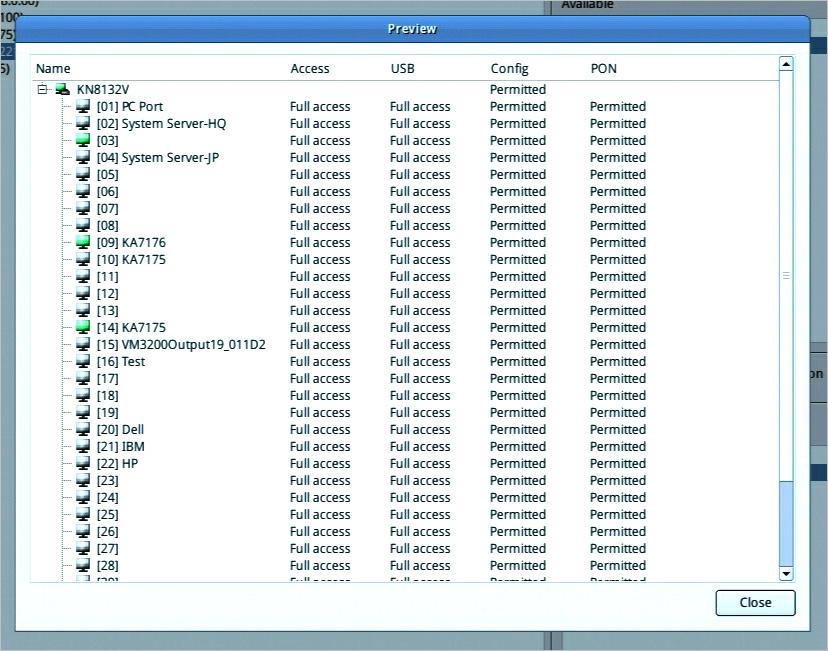
50 40
51 Chapter 5. System Configuration Device Management This page shows device information and allows you to configure network, ANMS and security settings. Note: Whenever a new setting is saved, the system will reboot. Device Information Click Device under Device Management in the left-hand side menu to bring out the information page. The Device Information page displays the name of the selected device, its firmware version, the FPGA (Field-Programmable-Gate-Array) and information about its network configuration. Double-click the Device Name (KA8278 in our example) to change the device name. Network The Network page is used to specify the network environment. Click Network under Device Management in the left-hand side menu to bring out the information page. 41
52 Each of the elements on this page is described below. IP Installer The IP Installer is an external Windows-based utility for assigning IP addresses to the KVM over IP switch. Click one of the radio buttons to select Enable, View Only, or Disabled for the IP Installer utility. See IP Installer, page 268, for IP Installer details. 42
53 Chapter 5. System Configuration Note: 1. If you select View Only, you will be able to see the KVM over IP switch in the IP Installer s Device List, but you will not be able to change the IP address. 2. For security, we strongly recommend that you set this to View Only or Disable after each use. IPv4 Settings IP Address: IPv4 is the traditional method of specifying IP addresses. The KVM over IP Console Station can either have its IP address assigned dynamically (DHCP), or it can be given a fixed IP address. For dynamic IP address assignment, select Obtain IP address automatically (default). To specify a fixed IP address, select Set IP address manually and fill in the fields with values appropriate for your network. Note: 1. If you choose Obtain IP address automatically, when the console station starts up it waits to get its IP address from the DHCP server. If it has not obtained the address after one minute, it automatically reverts to its factory default IP address ( ) 2. If the switch is on a network that uses DHCP to assign network addresses, and you need to ascertain its IP address, see Supported KVM Switches on page 94 for information. DNS Server For automatic DNS Server address assignment, select Obtain DNS Server address automatically. To specify the DNS Server address manually, select Set DNS server address manually, and fill in the addresses for the Preferred and Alternate DNS servers with values appropriate for your network. Note: Specifying the Alternate DNS Server address is optional. 43
54 IPv6 Settings At present, the KVM over IP console station supports three IPv6 address protocols: Link Local IPv6 Address, IPv6 Stateless Autoconfiguration, and Stateful Autoconfiguration (DHCPv6). IP Address: IPv6 is the new (128-bit) format for specifying IP addresses. The KVM over IP console station can either have its IPv6 address assigned dynamically (DHCP), or it can be given a fixed IP address. For dynamic IP address assignment, select Obtain IP address automatically (default). To specify a fixed IP address, select Set IP address manually and fill in the fields with values appropriate for your network. DNS Server For automatic DNS Server address assignment, select Obtain DNS Server address automatically. To specify the DNS Server address manually, select Set DNS server address manually, and fill in the addresses for the Preferred and Alternate DNS servers with values appropriate for your network. Note: Specifying the Alternate DNS Server address is optional. Finishing Up After making any network changes, be sure to click Save at the bottom of the configuration page. ANMS The ANMS (Advanced Network Management Settings) page is used to set up login authentication and authorization management from external sources. Click ANMS under Device Management in the left-hand side menu to bring out the information page. 44

55 Chapter 5. System Configuration RADIUS Settings To allow authentication and authorization for the KVM over IP Console Station through a RADIUS server, do the following: 1. Check Enable. 2. Select Preferred or Alternate RADIUS server. 3. Fill in the IP addresses and service port numbers for the Preferred and Alternate RADIUS servers. You can use the IPv4 address, the IPv6 address or the domain name in the IP fields. 4. Select the Authentication Type: PAP or CHAP. 45
56 5. In the Timeout field, set the time in seconds that the KVM over IP console station waits for a RADIUS server reply before it times out. 6. In the Retries field, set the number of allowed RADIUS retries. 7. In the Shared Secret field, key in the character string that you want to use for authentication between the KVM over IP console station and the RADIUS Server. A minimum of 6 characters is required. 8. On the RADIUS server, Users can be authenticated with any of the following methods: Set the entry for the user as su/xxxx Where xxxx represents the Username given to the user when the account was created on the KVM over IP console station. Use the same Username on both the RADIUS server and the KVM over IP console station. Use the same Username name on both the RADIUS server and the KVM over IP console station. In each case, the user s access rights are the ones assigned that were assigned when the User of Group was created on the KVM over IP console station (see Adding Device on page 27). AD / LDAP Settings To allow authentication and authorization for the KVM over IP console station via AD / LDAP, refer to the information in the table, below: Item Enable Type Server IP Timeout Action Check the checkbox to enable AD / LDAP authentication and authorization. Click the drop down menu to select between AD / LDAP. Select Preferred or Alternate LDAP Server and fill in the IP address and port number for the LDAP or LDAPS server. You can use the IPv4 address, the IPv6 address or the domain name in the LDAP Server field. For LDAP, the default port number is 389. This is the time in seconds that the KVM over IP console station waits for an AD or LDAP server reply before it times out. 46
57 Chapter 5. System Configuration Item Admin DN Admin Name Password Search DN Action Consult the AD / LDAP administrator to ascertain the appropriate entry for this field. For example, the entry might look like this: ou=kn8132,dc=aten,dc=com Key in the administrator username. Key in the administrator password. Set the distinguished name of the search base. This is the domain name where the search starts for user names. LDAP attribute is required for complete setup. LDAP attribute can be retrieved from the GET command using the Terminal interface. Please refer to Terminal on page 59 for more details. On the AD / LDAP server, users can be authenticated with any of the following methods: With MS Active Directory schema. Without schema Only the Usernames used on the KVM over IP console station are matched to the names on the LDAP server. User privileges are the same as the ones configured on the switch. Without schema Only Groups in AD are matched. User privileges are the ones configured for the groups he belongs to on the switch. Without schema Usernames and Groups in AD are matched. User privileges are the ones configured for the User and the Groups he belongs to on the switch. Note: For more information on configuring LDAP, you can download the full LDAP instructional manual from our website. Finishing Up After making any ANMS changes, be sure to click Save at the bottom of the configuration page. 47

58 Security The Security page is divided into 3 main panels, as described in the sections that follow. Click Security under Device Management in the left-hand side menu to bring out the information page. Login Failures For increased security, the Login Failures section allows administrators to set policies governing what happens when a user fails to log in successfully. To set the Login Failures policy, check the Enable checkbox (the default is for Login Failures to be enabled). The meanings of the entries are explained in the table below: 48
59 Chapter 5. System Configuration Allowed Timeout Entry Explanation Sets the number of consecutive failed login attempts that are permitted from a remote computer. The default is 5 times. Sets the amount of time a remote computer must wait before attempting to login again after it has exceeded the number of allowed failures. The default is 3 minutes. Note: If Login Failures is not enabled, users can attempt to log in an unlimited number of times with no restrictions. For security purposes, we recommend that you enable this function and enable the lockout policies. Account Policy In the Account Policy section, system administrators can set policies governing usernames and passwords. The meanings of the Account Policy entries are explained in the table below: Entry Minimum Username Length Minimum Password Length Password must Contain at least Enforce Password History Explanation Sets the minimum number of characters required for a username from 1 to 32. The default is 6. Sets the minimum number of characters required for a password from 0 to 32. A setting of 0 means that no password is required. Users can login with only a username. The default is 6. Checking any of these items requires users to include at least one uppercase letter, one lowercase letter, or one number in their password. Note: This policy only affects user accounts created after this policy has been enabled and password changes to existing user accounts. Check this to prevent users from logging in with the same account at the same time. 49
60 Working Mode An explanation of the Working Mode items is given in the table below: Item Enable ICMP Allow Push Request from Remote Allow Pull Request from Remote Console Keyboard Language Explanation Check/uncheck to allow/disallow the KVM over IP console station to be pinged. The default is Enabled. Check/uncheck to allow/disallow another KVM over IP console station to push configuration or FW to your console station. Check/uncheck to allow/disallow another KVM over IP console station to pull configuration from your console station. Click the drop down menu to select the console s local keyboard language. Finishing Up After making any Security changes, be sure to click Save at the bottom of the configuration page. 50
61 Chapter 5. System Configuration Maintenance The Maintenance function is used to upgrade firmware; backup and restore configuration and account information; Push/pull configurations; send terminal commands, ping network devices; and restore default values. Upgrade Main Firmware As new versions of the firmware become available, they can be downloaded from our website. Check the website regularly to find the latest information and packages. Click Upgrade Main Firmware under Maintenance in the left-hand side menu to bring out the information page. To upgrade the main firmware: 1. Getting the newest firmware by downloading the firmware from Aten s website to a computer. 2. Unzip the.zip file for the.csf file and transfer it to a USB flash drive. Note: Please use FAT file system formatted USB flash drive(s). 3. Remove the USB flash drive from the computer and insert it to a USB port of the console station. 4. On the console station firmware page, click Choose File and a file management window will pop-up: 51

62 5. Navigate to the directory that the new firmware file is in, click to select the file and click Open. The file will be displayed in the Filename field of the configuration page as shown below: 6. Click Upgrade Main Firmware to start the upgrade procedure. If you enabled Check Main Firmware Version the current firmware level is compared with that of the upgrade file. If the current version is equal to or higher than the upgrade version, a popup message appears, to inform you of the situation and stops the upgrade procedure. If you didn't enable Check Main Firmware Version, the upgrade file is installed without checking what its level is. Upgrade progress information is shown in a Progress bar. Once the upgrade completes successfully, the console station will restart. 7. Log in again and check if the firmware version is the newest one. 52
63 Chapter 5. System Configuration Note: To recover from a failed upgrade situation, see Firmware Upgrade Recovery on page 53. Firmware Upgrade Recovery Should the console station s main firmware upgrade procedure fail, and the console station becomes unusable, follow the firmware upgrade recovery procedure below to recover the console station to its original firmware version: 1. Power off the console station by unplugging the power adapter. 2. Press and hold the Reset Switch in using a sharp object. 3. While holding the Reset Switch in, power up the console station by replugging the power adapter. This reverts the console station to use the original factory installed firmware. Try upgrading the main firmware again when the console station is operational (see Upgrade Main Firmware on page 51). Backup / Restore Backup/Restore gives you the ability to back up the console station s configuration and user profile information. Click Backup/Restore under Maintenance in the left-hand side menu to bring out the information page. 53
64 Backup To backup the device s settings: Note: A USB flash drive is required to be connected to the console station to store the backup file. 1. (Optional) In the Password field, key in a password for the file. Note: 1. Setting a password is optional. If you do not set one, the file can be restored without specifying a password. 2. If you do set a password, make a note of it, since you will need it to be able to restore the file. 2. Click Backup. A file management window will pop-up as shown below: 54
65 Chapter 5. System Configuration 3. In the File name field, enter a backup file name and click Save. The system will display a success message to indicate successful backup. Restore To restore a previously-saved settings: Note: A USB flash drive with the previously backed-up file is required to be connected to the console station for backup file retrieval. 1. Click the Choose File button for the file management window: 55

66 2. Where applicable, go to the directory with the backup file (.cfg), click to select the file (highlighted as shown above) and click Open. 3. If you set a password when you created the file, key it in the Password field. 4. Select as many of the options that are presented as you wish to restore. 5. Click Restore. The system will display a success message to indicate the restoration was successful. A Your system will automatically restart in one minute message will follow the success message above before the system restarts. Push / Pull Configuration Push / Pull Configuration gives you the ability to deploy or retrieve your settings to or from other console stations. Click Push cfg. / Pull cfg. under Maintenance in the left-hand side menu to bring out the information page. 56
67 Chapter 5. System Configuration Pull Configuration To pull (retrieve) a configuration to your console station: 1. Enter the device s IP address or IPv6 Address you wish to retrieve the configuration from. Alternatively, you can mouse over the magnifying glass to find a list of the devices on the same LAN and click the device s IP or IPv6 address: 2. Enter the administrative username and password of the selected device. 57
68 3. Select the information you would like to retrieve to your console station by checking the checkbox(es). Note: Firmware files cannot be retrieved. If you check the Firmware checkbox, the Pull button will not be available. 4. Click Pull to retrieve the information. The console station will restart after successfully retrieving the information. Push Configuration To push (deploy) a configuration from your console station: Note: You can deploy the configuration / FW to multiple devices using one procedure (shown below) instead of one procedure for every device. 1. Enter the device s IP address(es) or IPv6 Address(es) you wish to deploy the configuration to. Alternatively, you can mouse over the magnifying glass to find a list of the devices on the same LAN and click the device s IP or IPv6 address: 2. Enter the administrative username and password of the selected device(s). 3. Select the information you would like to deploy from your console station by checking the checkbox(es). Note: If you checked the Firmware checkbox, please remember to click the Choose button to select a firmware from a USB flash drive. 4. Click Push to deploy the information. 58
69 Chapter 5. System Configuration The console station(s) will restart after successfully receiving the deployment information. Terminal Terminal provides a command line to execute options using a terminal interface. Type a command in the window and hit [Enter] to execute it. Click Terminal under Maintenance in the left-hand side menu to bring out the terminal page. Note: Expand the submenu by clicking the + symbol if Terminal is not shown. Available commands include: GET => Gets current configuration. HELP => Provides Help information for commands. CLEAR => Clears the screen. PING => Displays ping host information. SETLDAPMEMBER => Sets new value for ldap member. SETLDAPMEMBEROF => Sets new value for ldap memberof. SETPROMPT => Sets prompt string. TRACERT => Displays trace route information. DEVICEHISTORY => Clear/Enable/Disable device list history SELFDIAGNOSTIC => Self Diagnostic 59

70 System Operation The System Operation page lets you restore certain configuration changes that were made to the KVM over IP console station back to their original factory default values. Reset Default Values Clicking this button undoes all Customization page changes that have been made to the KVM over IP console station and returns the parameters to the original factory default settings. The system will ask for confirmation: Click Yes to go ahead. The system will restart after the reset. Click No to cancel operation. Reset on exit: If you checked the checkbox, the system will ask if you would like to reset the KVM over IP console station (and implement all the new settings) upon exiting the System Configuration page. 60
, the checkbox is automatically checked and the console station will reset when you exit the page.")
71 Chapter 5. System Configuration Click Yes to go ahead with the reset (the system will also reboot). Click No if you do not want the system to be reset. If you change the console station s IP Address (see Network on page 41), the checkbox is automatically checked and the console station will reset when you exit the page. If you clear the check mark before exiting the page, the changed IP settings will be ignored and the original IP address settings will remain in effect. Note: Even though the changed IP settings are ignored, they still remain in the network settings fields. Which means that the next time you open this page the Reset on exit checkbox will automatically be enabled, and when the console station resets, the new IP settings that you thought you discarded will become the ones used by the console station. To avoid this problem, you should go back to the network settings page and be sure that the IP settings that appear in the fields are the ones you want to use. 61

72 Quick User Configuration The user icon allows quick access to password change, configure preferences, logout, restart the system, shut down the system, or display quick information about the console station. Click the User icon for its menu: Option Change Password User Preferences Logout Restart Shutdown About Description Click this option to change the password of the current user. Select the preferred language from the scroll menu. Language change will be shown immediately. Logout Timeout is the idle time period (no actions) where the system automatically logs you out. Set a logout timeout time in minutes. Enter 0 if you do not want the system to log you out from idling. Click this option to log out of the system. Click this option to restart the system. Click this option to safely shut down the system. This is recommended way to shut down the system. Pull the power adapter after the system display a safe-to-shutdown message. Click this option to display the KVM over IP console station s device name, firmware version, IP address, and IPv6 address 62

73 Chapter 6. Toolbar Interface Chapter 6 Toolbar Interface Overview The KVM over IP console station s interface provides a toolbar to help you with the remote control operations on the captured port. The toolbar is usually hidden. To bring up the toolbar, locate a down arrow symbol as shown: Mouse over the down arrow symbol to bring up the toolbar. The meanings of the toolbar icons are explained in the table below: Icon Purpose Video icon This icon brings up the video settings. Please see Video Settings on page 65 for more details. Macros icon This icon provides access to three functions found in the Macros dialog box: Hotkeys, User Macros, and System macros. Please see Macros on page 67 for more details. 63
74 Icon Purpose Mouse Sync Mode icon This provides automatic locked-in synching of the remote and local mouse pointers eliminating the need to constantly resync the two movements. Click the icon to toggle between Auto Mouse Sync Mode (mouse icon with an A) and Manual Mouse Sync Mode (mouse icon with an M). Please see Mouse Sync Mode on page 79 for more details. Connect icon Click for a list of available ports. Click to select the port you wish to connect to. Configuration icon Click for further configurations. Please see Further Configuration on page 74. Exit Remote Location There are two ways to exit from the remote control operations on the captured port. 1. Click Back On the toolbar interface, click the Configuration icon for more operation options. Click Back to exit remote location. 2. Use Macros By default, pressing the Exit Remote Location hot keys (F2, F3, F4) will also exit remote location. Note: Use the updated hot keys should there be a change to this function s hot key. 64

75 Chapter 6. Toolbar Interface Video Settings Click the Video icon on the toolbar to bring up the Video Settings dialog box. The options in the basic dialog box allow you to adjust the Screen Position, set Auto Sync, slide-to-adjust Performance bar setting, Enhanced Text Mode, slide-to-adjust Video Quality bar, and Set to Grayscale. The meanings of the video adjustment options are given in the table below: Options Screen Position Description / Operation Adjust the horizontal and vertical position of the remote server window by clicking the Arrow buttons. 65
76 Options Video Auto-Sync Preset / Customization Performance Enhanced Text Mode Video Quality Set to Grayscale Description / Operation Click Video Auto Sync to have the vertical and horizontal offset values of the remote screen detected and automatically synchronized with the local screen. Note: 1. If the local and console station mouse pointers are out of sync, in most cases, performing this function will bring them back into sync. 2. This function works best with a bright screen. 3. If you are not satisfied with the results, use the Screen Position arrows (on the right) to position the remote display manually. Using the Preset and Custom buttons allow you to set and save custom video settings, and revert back to default video settings. Use the slide bar to select the type of Internet connection that the console station uses. Dragging the performance bar will also automatically adjust the Video Quality settings to optimize the quality of the video display. Since network conditions vary, if none of the preset choices seem to work well, you can use the Video Quality slide bar to adjust the settings to suit your conditions. Check to enhance color and video quality, especially for texts. Drag the slider bar to adjust the overall Video Quality. The larger the value, the clearer the picture and the more video data goes through the network. Depending on the network bandwidth, a high value may adversely effect response time. Check to set video display to grayscale. 66

77 Chapter 6. Toolbar Interface Macros The Macros icon provides access to three functions found in the Macros dialog box: Hotkeys, User Macros, and System Macros. Each of these functions is described in the following sections. Hotkeys Various actions related to manipulating the remote server can be accomplished with hotkeys. The Hotkey Setup utility (accessed by clicking this icon), lets you configure which hotkeys perform the actions. Each action in the Actions column corresponds to the hot keys in the HotKey column on the same row. Check the checkbox in the Enable column on the same row to enable its hotkey. To change the hotkey for an action: 1. If you are not in the Hotkeys tab, click to select to go into the Hotkeys page. 2. Highlight the Action and click Set Hotkey for the window dialog below: 67
78 3. Press your selected Function keys (one at a time). The key names will appear in the Hotkeys field as you press them. You can use the same function keys for more than one action, as long as the key sequence is not the same. To cancel setting a hotkey value, click Cancel; to clear an action s Hotkeys field, click Clear. 4. When you have finished keying in your sequence, click Save. To reset all the hotkeys to their default values, click Reset. An explanation of the Hotkey actions is given in the table below: Action Exit Remote Location Adjust Video Adjust Mouse Video Auto-Sync Explanation Breaks the connection to the KVM over IP console station and returns you to console station operation. This is equivalent to clicking the Back option under the Configuration icon of the toolbar. The default keys are F2, F3, F4. Brings up the Video Settings dialog box. This is equivalent to clicking the Video Settings icon on the console station toolbar. The default keys are F5, F6, F7. This synchronizes the local and remote mouse movements. The default keys are F8,F7,F6. This combination performs an auto-sync operation. It is equivalent to clicking the Video Auto Sync button in the Video Settings dialog box. The default keys are F6,F7,F8. 68
79 Chapter 6. Toolbar Interface Action Show / Hide Local Cursor Explanation Toggles off and on: hides local cursor and locks the mouse pointer and keyboard use within the Windows/Java Client AP window, plus hides the control panel. This is equivalent to selecting the Single pointer type from the Mouse Pointer option under the Configuration icon of the toolbar. The default keys are F4,F5. User Macros User Macros are created to perform specific actions on the remote server. To create a macro, do the following: 1. If you are not in the Macros tab, click to select to go into the Macros page. 2. Select User Macros and click the + symbol. 69

80 3. In the dialog box, you can choose to replace the New Macro text with a name of your choice for the macro. 4. Click Set Macro followed by Record. The dialog box disappears as a small panel appears at the top left of the screen: 5. Press the keys for the macro. To pause macro recording, click Pause. To resume, click Pause again. Clicking Cancel cancels all keystrokes. Note: 1. Case is not considered typing A or a has the same effect. 2. Only the default keyboard characters may be used. Alternate characters cannot be used. For example, if the keyboard is Traditional Chinese and default character is A the alternate Chinese character obtained via keyboard switching is not recorded. 70

81 Chapter 6. Toolbar Interface 6. When finished, click Stop. You will return to the Macros dialog box with your macro key presses displayed in the Macro column: 7. If you want to change any of the keystrokes, select the macro, click Set Macro followed by Edit. This brings up a dialog box. You can change the content of your keystrokes, change their order, etc. 71
. 2. By playing it in this dialog box.")

82 8. Click Save to save the changes, or click Cancel to cancel the changes. Both option will return you to the Macros dialog box. 9. Repeat the procedure for any other macros you wish to create. After creating your macros, you can run them in any of three ways: 1. By using the hotkey (if one was assigned). 2. By playing it in this dialog box. If you run the macro from this dialog box, you have the option of specifying how the macro runs. Click the down arrow symbol to select your option. No Wait: The macro runs the key presses one after another with no time delay between them. Time Ctrl (time control): The macro waits for the amount of time between key presses that you took when you created it. If you click the Play symbol without selecting an option, the macro runs with the default choice (No Wait or Time Ctrl), which is shown in the Playback Mode column. You can change the default choice by clicking on the current choice (No Wait in the screenshot above), and selecting the alternate choice. Import / Export Macros The import / export function allows you to import or export macros from or to a USB flash drive. Click the import symbol to search through the USB flash drive to import the macros. 72

83 Chapter 6. Toolbar Interface Click the export symbol and enter a name to save the macros to the USB flash drive. Delete Macros To delete a macro, click to select the macro and click the trash can symbol to delete a macro. Search Macros The search function (on the top right-hand side of the dialog box) lets you filter the list of macros that appear in the list. Click the drop-down arrow (next to the magnifying glass icon) to choose whether you want to search by name or by key; enter a string in the search field for the search; then click the Search symbol (magnifying glass symbol). All instances that match your search string appear in the list. System Macros System Macros are used to create exit macros for when you close a session. For example, as an added measure of security, you could create a macro that sends the Winkey-L combination which would cause the remote server s login page to come up the next time the device was accessed. Ways to create, delete or search for macros are the same as User Macros, please refer to User Macros on page 69. System macros cannot be imported or exported. 73

84 For more information on system macros for different KVM over IP switches, please refer to their user manuals. Further Configuration More configuration options are available when clicking the configuration icon: Options Switch Display Video Auto-Sync Virtual Media Message Board Speaker Mouse Pointer Mouse Sync Mode Description When you have a dual-display model (KA8278 or KA8288) and have both displays connected, this option will appear to allow you to switch between the two displays. Click to perform a video and mouse autosync operation. It is the same as clicking the Auto Sync button in the Video Options dialog box (see Video Settings on page 65). Click to bring up the Virtual Media dialog box. See Virtual Media on page 75 for specific details. Note: This icon displays in gray when the function is disabled or not available. Click to bring up the Message Board (see Message Board on page 77). Click to toggle sound from the remote server to be heard on the client computer s speakers on or off. The option is grayed out when the speaker is toggled Off. Mouse over the option and click to select the mouse pointer type. Note: In the main GUI page, only Dual and Crosshairs are available. In a port page, three pointers are available. Mouse over the option and click to select the mouse sync mode. Please see Mouse Sync Mode on page

85 Chapter 6. Toolbar Interface Options Open GUI Back About Description Click to open the GUI of the connected KVM over IP switch. Please refer to the user manual of the connected KVM over IP switch for more details. Click to return to the page on the KVM over IP Console Station that brought you here. Click to get information about this connection. The information include Device Name, IP Address, Current Port, Video Mode and Channel / User Numbers. Virtual Media The Virtual Media feature allows a USB removable disk on a user s system to appear and act as if it were installed on the remote server. To mount a virtual media device: 1. Click the Virtual Media icon to bring up the Virtual Media dialog box: 2. Click the + symbol and select the media source. 75
86 3. If your device only supports full speed USB, check the Disable High Speed USB Operation Mode checkbox. 4. To add additional media sources, click the + symbol, and select the source as many times as you require. Up to two virtual media choices can be mounted. The top three in the list are the ones that are selected. Virtual Media and Smart Card readers can be mounted at the same time. To rearrange the selection order, highlight the device you want to move, then click the Up or Down Arrow button to promote or demote it in the list. 5. Read refers to the redirected device being able to send data to the remote server; Write refers to the redirected device being able to have data from the remote server written to it. For the redirected device to be writable as well as readable, click to put a check in the Enable Write checkbox: Note: If a redirected device cannot be written to, it appears in gray. 6. To remove an entry from the list, select it and click the trash can icon. 7. After you have made your media source selections, click Mount. The dialog box closes. The virtual media devices that you have selected are redirected to the remote server, where they show up as drives on the remote server s file system. Once mounted, you can treat the virtual media as if they really existed on the remote server drag and drop files to/from them; 76
87 Chapter 6. Toolbar Interface open files on the remote server for editing and save them to the redirected media, etc. 8. To end the redirection, bring up the Control Panel and click on the Virtual Media icon. All mounted devices are automatically unmounted. Message Board The KVM over IP console station supports multiple user logins, which may cause access conflicts. To alleviate the problem, a message board has been provided, which allows users to communicate with each other. Buttons The buttons in the dialogue box toggles actions and are described in the table below: Button Action Enable/Disable Chat. When disabled, messages posted to the board are not displayed. The button is shadowed when Chat is disabled. The icon displays next to the user's name in the User List panel when the user has disabled Chat. 77
88 Button Action Occupy/Release Keyboard/Video/Mouse. When you Occupy the KVM, other users cannot see the video, and cannot input keyboard or mouse data. The button is shadowed when the KVM is occupied. The icon displays next to the user's name in the User List panel when the user has occupied the KVM. Occupy/Release Keyboard/Mouse. When you Occupy the KM, other users can see the video, but cannot input keyboard or mouse data. The button is shadowed when the KM is occupied. The icon displays next to the user's name in the User List panel when the user has occupied the KM. Show/Hide User List. When you Hide the User List, the User List panel closes. The button is shadowed when the User List is open. Message Display Panel Messages that users post to the board - as well as system messages - display in this panel. If you disable Chat, however, messages that get posted to the board will not appear. Compose Panel Key in the messages that you want to post to the board in this panel. Click Send to post the message to the board. User List Panel The names of all the logged in users are listed in this panel. Your name appears in blue; other users' names appear in black. By default, messages are posted to all users. To post a message to one individual user, select the user's name before sending your message. If a user's name is selected, and you want to post a message to all users, select All Users before sending your message. If a user has disabled Chat, the disable chat icon will be displayed on the left of user's name. If a user has occupied the KVM or the KM, the corresponding icon will be displayed on the left of the user s name. 78

89 Chapter 6. Toolbar Interface Mouse Sync Mode Synchronization of the local and remote mouse pointers is accomplished either automatically or manually. Automatic Mouse Synchronization This provides automatic locked-in synching of the remote and local mouse pointers eliminating the need to constantly resync the two movements. Manual Mouse Synchronization If the local mouse pointer goes out of sync with the remote system's mouse pointer there are a number of methods to bring them back into sync: 79
Multi-View KVMP TM Switch User Manual
 Multi-View KVMP TM Switch User Manual www.aten.com EMC Information FEDERAL COMMUNICATIONS COMMISSION INTERFERENCE STATEMENT: This equipment has been tested and found to comply with the limits for a Class
KVM over IP Matrix System KE6900 / KE6900ST / KE6940 / KE8950 / KE8952 CCKM KE Management Software User Manual
 KVM over IP Matrix System KE6900 / KE6900ST / KE6940 / KE8950 / KE8952 CCKM KE Management Software User Manual www.aten.com KVM over IP Matrix System User Manual EMC Information FEDERAL COMMUNICATIONS
KVM Over IP Matrix System KE6900 / KE6900ST / KE6940 / KE8950 / KE8952 / CCKM KE Management Software User Manual
 KVM Over IP Matrix System KE6900 / KE6900ST / KE6940 / KE8950 / KE8952 / CCKM KE Management Software User Manual www.aten.com EMC Information FEDERAL COMMUNICATIONS COMMISSION INTERFERENCE STATEMENT: This
KVM over IP Matrix System KE6900 / KE6900ST / KE6940 / KE8950 / KE8952 CCKM KE Matrix Manager Software User Manual
 KVM over IP Matrix System KE6900 / KE6900ST / KE6940 / KE8950 / KE8952 CCKM KE Matrix Manager Software User Manual www.aten.com EMC Information FEDERAL COMMUNICATIONS COMMISSION INTERFERENCE STATEMENT:
4x4 / 8x8 True 4K HDMI Matrix Switch VM0404HB / VM0808HB User Manual
 4x4 / 8x8 True 4K HDMI Matrix Switch VM0404HB / VM0808HB User Manual www.aten.com EMC Information FEDERAL COMMUNICATIONS COMMISSION INTERFERENCE STATEMENT: This equipment has been tested and found to comply
USB-C Multiport Dock with Power Charging USER MANUAL UH3230
 USB-C Multiport Dock with Power Charging USER MANUAL UH3230 EMC Information Federal Communication Commission Interference Statement: This equipment has been tested and found to comply with the limits for
8 x 8 HDMI Matrix Switch with Scaler VM5808H User Manual
 8 x 8 HDMI Matrix Switch with Scaler VM5808H User Manual www.aten.com EMC Information FEDERAL COMMUNICATIONS COMMISSION INTERFERENCE STATEMENT This equipment has been tested and found to comply with the
KVM Switch KH1508A / KH1516A / KH1532A User Manual
 KVM Switch KH1508A / KH1516A / KH1532A User Manual www.aten.com EMC Information FEDERAL COMMUNICATIONS COMMISSION INTERFERENCE STATEMENT: This equipment has been tested and found to comply with the limits
KVM Switch KH2508A / KH2516A User Manual
 KVM Switch KH2508A / KH2516A User Manual www.aten.com EMC Information FEDERAL COMMUNICATIONS COMMISSION INTERFERENCE STATEMENT: This equipment has been tested and found to comply with the limits for a
HDMI Optical Extender USER MANUAL VE882 / VE892
 HDMI Optical Extender USER MANUAL VE882 / VE892 EMC Information FEDERAL COMMUNICATIONS COMMISSION INTERFERENCE STATEMENT: This equipment has been tested and found to comply with the limits for a Class
Thunderbolt 3 Multiport Dock USER MANUAL UH7230
 Thunderbolt 3 Multiport Dock USER MANUAL UH7230 EMC Information Federal Communication Commission Interference Statement: This equipment has been tested and found to comply with the limits for a Class B
Master View Max Slideaway LCD KVM Switch CL-1758 User Manual
 Master View Max Slideaway LCD KVM Switch CL-1758 User Manual www.aten.com FCC Information This is an FCC Class A product. In a domestic environment this product may cause radio interference in which case
FCC Information. RoHS SJ/T
 FCC Information Federal Communication Commission Interference Statement: This equipment has been tested and found to comply with the limits for a Class B digital service, pursuant to Part 15 of the FCC
User Manual. 8/16-Port USB PS/2 Combo KVMP Switch GCS1808/GCS1716. PART NO. M1102-a/M1074-a. 1
 User Manual 8/16-Port USB PS/2 Combo KVMP Switch GCS1808/GCS1716 PART NO. M1102-a/M1074-a 1 www.iogear.com Package Contents 1 x 8/16-Port USB PS/2 Combo KVMP Switch 1 x PS/2 KVM Cable 1 x USB KVM Cable
NRGence Energy Box EC1000 User Manual
 NRGence Energy Box EC1000 User Manual www.aten.com FCC, CE Information Warning: This is a class A product. In a domestic environment this product may cause radio interference in which case the user may
KVM Over the NET KN2132 / KN4116 / KN4132 User Manual
 KVM Over the NET KN2132 / KN4116 / KN4132 User Manual www.aten.com FCC Information This is an FCC Class A product. In a domestic environment this product may cause radio interference in which case the
User Manual CL
 User Manual CL-1200 Warning! This is a class A product. In a domestic environment this product may cause radio interference in which case the user may be required to take adequate measures. This equipment
4-Port USB KM Switch CS724KM User Manual
 4-Port USB KM Switch CS724KM User Manual www.aten.com EMC Information FEDERAL COMMUNICATIONS COMMISSION INTERFERENCE STATEMENT: This equipment has been tested and found to comply with the limits for a
8x8 4K HDMI Matrix Switch VM0808HA User Manual
 8x8 4K HDMI Matrix Switch VM0808HA User Manual www.aten.com EMC Information FEDERAL COMMUNICATIONS COMMISSION INTERFERENCE STATEMENT This equipment has been tested and found to comply with the limits for
USB KVM Switch USER MANUAL CS62US / CS64US
 USB KVM Switch USER MANUAL CS62US / CS64US EMC Information FEDERAL COMMUNICATIONS COMMISSION INTERFERENCE STATEMENT: This equipment has been tested and found to comply with the limits for a Class B digital
Power over the NET PN9108 User Manual
 Power over the NET PN9108 User Manual www.aten.com FCC, CE Information FEDERAL COMMUNICATIONS COMMISSION INTERFERENCE STATEMENT: This equipment has been tested and found to comply with the limits for a
VS-1601.book Page i Tuesday, January 16, :15 PM User Manual VS1601
 User Manual VS1601 FCC Information This is an FCC Class A product. In a domestic environment this product may cause radio interference in which case the user may be required to take adequate measures.
4x4 / 8x8 HDMI Matrix Switch with Scaler VM5404H / VM5808H User Manual
 4x4 / 8x8 HDMI Matrix Switch with Scaler VM5404H / VM5808H User Manual www.aten.com EMC Information FEDERAL COMMUNICATIONS COMMISSION INTERFERENCE STATEMENT: This equipment has been tested and found to
LCD KVM Switch CL5808/CL5816 User Manual
 LCD KVM Switch CL5808/CL5816 User Manual www.aten.com FCC, CE Information FEDERAL COMMUNICATIONS COMMISSION INTERFERENCE STATEMENT: This equipment has been tested and found to comply with the limits for
DVI Video Switch USER MANUAL VS-261 / VS-461
 DVI Video Switch USER MANUAL VS-261 / VS-461 FCC Information This equipment has been tested and found to comply with the limits for a Class B digital device, pursuant to Part 15 of the FCC Rules. These
8/16-port USB HDMI KVM Switch CS1798 / CS17916 User Manual
 8/16-port USB HDMI KVM Switch CS1798 / CS17916 User Manual www.aten.com EMC Information FEDERAL COMMUNICATIONS COMMISSION INTERFERENCE STATEMENT: This equipment has been tested and found to comply with
Dual Rail LCD KVM Switch KL9108 / KL9116 User Manual
 Dual Rail LCD KVM Switch KL9108 / KL9116 User Manual www.aten.com FCC, CE Information FEDERAL COMMUNICATIONS COMMISSION INTERFERENCE STATEMENT: This equipment has been tested and found to comply with the
8-port USB DVI KVM Switch CS1768 / CS1788 User Manual
 8-port USB DVI KVM Switch CS1768 / CS1788 User Manual www.aten.com EMC Information FEDERAL COMMUNICATIONS COMMISSION INTERFERENCE STATEMENT: This equipment has been tested and found to comply with the
KVM over IP CS1708i / CS1716i Full HD Version User Manual
 KVM over IP CS1708i / CS1716i Full HD Version User Manual www.aten.com EMC Information FEDERAL COMMUNICATIONS COMMISSION INTERFERENCE STATEMENT: This equipment has been tested and found to comply with
Hideaway LCD KVM Switch KL3116 User Manual
 Hideaway LCD KVM Switch KL3116 User Manual www.aten.com FCC Information This is an FCC Class A product. In a domestic environment this product may cause radio interference in which case the user may be
DVI Dual View KVM Extender CE604 User Manual
 DVI Dual View KVM Extender CE604 User Manual www.aten.com EMC Information FEDERAL COMMUNICATIONS COMMISSION INTERFERENCE STATEMENT: This equipment has been tested and found to comply with the limits for
CS-231. User Manual. Copyright ATEN International Co., Ltd. Manual Part No. PAPE G Printing Date: 11/2006
 User Manual CS-231 Read this guide thoroughly and follow the installation and operation procedures carefully in order to prevent any damage to the units and/or any devices that connect to them. This package
16 x 16 HDMI Matrix Switch with Scaler VM51616H User Manual
 16 x 16 HDMI Matrix Switch with Scaler VM51616H User Manual www.aten.com EMC Information FEDERAL COMMUNICATIONS COMMISSION INTERFERENCE STATEMENT: This equipment has been tested and found to comply with
DVI HDBaseT KVM Extender with ExtremeUSB CE610A User Manual
 DVI HDBaseT KVM Extender with ExtremeUSB CE610A User Manual www.aten.com EMC Information FEDERAL COMMUNICATIONS COMMISSION INTERFERENCE STATEMENT: This equipment has been tested and found to comply with
Cat 5 High-Density KVM Over the NET KH1508Ai / KH1516Ai Full HD Version User Manual
 Cat 5 High-Density KVM Over the NET KH1508Ai / KH1516Ai Full HD Version User Manual www.aten.com EMC Information FEDERAL COMMUNICATIONS COMMISSION INTERFERENCE STATEMENT: This equipment has been tested
2-Port USB DisplayPort KVM Switch USER MANUAL CS782DP
 2-Port USB DisplayPort KVM Switch USER MANUAL CS782DP EMC Information FEDERAL COMMUNICATIONS COMMISSION INTERFERENCE STATEMENT: This equipment has been tested and found to comply with the limits for a
DVI KVM over IP CN8600 User Manual
 DVI KVM over IP CN8600 User Manual www.aten.com EMC Information FEDERAL COMMUNICATIONS COMMISSION INTERFERENCE STATEMENT: This equipment has been tested and found to comply with the limits for a Class
8-Port True 4K HDMI Switch VS0801HB User Manual
 8-Port True 4K HDMI Switch VS0801HB User Manual www.aten.com VS0801HB User Manual Preface EMC Information FEDERAL COMMUNICATIONS COMMISSION INTERFERENCE STATEMENT: This equipment has been tested and found
2/4-Port VGA Switch with Audio VS0201 / VS0401 User Manual
 2/4-Port VGA Switch with Audio VS0201 / VS0401 User Manual www.aten.com FCC Information Federal Communication Commission Interference Statement: This equipment has been tested and found to comply with
2/4-Port VGA Switch with Audio VS0201 / VS0401 User Manual
 2/4-Port VGA Switch with Audio VS0201 / VS0401 User Manual www.aten.com VS0201 / VS0401 User Manual FCC Information Federal Communication Commission Interference Statement: This equipment has been tested
4 x 4 / 9 x 9 HDMI HDBaseT-Lite Matrix Switch VM3404H / VM3909H User Manual
 4 x 4 / 9 x 9 HDMI HDBaseT-Lite Matrix Switch VM3404H / VM3909H User Manual www.aten.com EMC Information FEDERAL COMMUNICATIONS COMMISSION INTERFERENCE STATEMENT: This equipment has been tested and found
Short Depth WideScreen LCD Console CL3800 / CL3700 / CL3100 User Manual
 Short Depth WideScreen LCD Console CL3800 / CL3700 / CL3100 User Manual www.aten.com EMC Information FEDERAL COMMUNICATIONS COMMISSION INTERFERENCE STATEMENT: This equipment has been tested and found to
8-Port VGA Switch with Auto Switching VS0801A User Manual
 8-Port VGA Switch with Auto Switching VS0801A User Manual www.aten.com VS0801A User Manual FCC Information FEDERAL COMMUNICATIONS COMMISSION INTERFERENCE STATEMENT: This equipment has been tested and found
Cat 5 High-Density KVM Over the NET KH1508Ai / KH1516Ai User Manual
 Cat 5 High-Density KVM Over the NET KH1508Ai / KH1516Ai User Manual www.aten.com FCC Information This is an FCC Class A product. In a domestic environment this product may cause radio interference in which
USB 2.0 DVI KVM Switch USER MANUAL CS682
 USB 2.0 DVI KVM Switch USER MANUAL CS682 EMC Information FEDERAL COMMUNICATIONS COMMISSION INTERFERENCE STATEMENT: This equipment has been tested and found to comply with the limits for a Class B digital
UEH4002A 4-port USB 2.0 CAT 5 Extender User Manual
 UEH4002A 4-port USB 2.0 CAT 5 Extender User Manual www.aten.com EMC Information Federal Communication Commission Interference Statement: This equipment has been tested and found to comply with the limits
DVI KVM Extender CE600 / CE602 User Manual
 DVI KVM Extender CE600 / CE602 User Manual www.aten.com CE600 / CE602 User Manual FCC Information This is an FCC Class A product. In a domestic environment this product may cause radio interference in
HDMI over IP Video Extender VE8900 / VE8950 User Manual
 HDMI over IP Video Extender VE8900 / VE8950 User Manual www.aten.com VE8900 / VE8950 User Manual EMC Information FEDERAL COMMUNICATIONS COMMISSION INTERFERENCE STATEMENT: This equipment has been tested
LCD KVMP Switch CL5708 / CL5716 User Manual
 LCD KVMP Switch CL5708 / CL5716 User Manual www.aten.com FCC Information This is an FCC Class A product. In a domestic environment this product may cause radio interference in which case the user may be
Single Rail 8-Port DVI FHD LCD KVM Switch CL6708MW User Manual
 Single Rail 8-Port DVI FHD LCD KVM Switch CL6708MW User Manual www.aten.com EMC Information FEDERAL COMMUNICATIONS COMMISSION INTERFERENCE STATEMENT: This equipment has been tested and found to comply
UEH Port USB 2.0 Cat 5 Extender over LAN. User Manual
 UEH4102 4-Port USB 2.0 Cat 5 Extender over LAN User Manual www.aten.com EMC Information FEDERAL COMMUNICATIONS COMMISSION STATEMENT: This equipment has been tested and found to comply with the limits for
4x4 / 8x8 DVI Matrix Switch with Scaler VM5404D / VM5808D User Manual
 4x4 / 8x8 DVI Matrix Switch with Scaler VM5404D / VM5808D User Manual www.aten.com EMC Information FEDERAL COMMUNICATIONS COMMISSION INTERFERENCE STATEMENT: This equipment has been tested and found to
Cat 5 High-Density Dual Rail LCD KVM Switch KL1508A / KL1516A User Manual
 Cat 5 High-Density Dual Rail LCD KVM Switch KL1508A / KL1516A User Manual www.aten.com FCC, CE Information FEDERAL COMMUNICATIONS COMMISSION INTERFERENCE STATEMENT: This equipment has been tested and found
LCD KVM Switch KL1116 User Manual
 LCD KVM Switch KL1116 User Manual www.aten.com FCC Information This is an FCC Class A product. In a domestic environment this product may cause radio interference in which case the user may be required
VE2812UST / VE2812EUT HDMI & VGA HDBaseT Transmitter with US / EU Wall Plate User Manual
 VE2812UST / VE2812EUT HDMI & VGA HDBaseT Transmitter with US / EU Wall Plate User Manual www.aten.com EMC Information FEDERAL COMMUNICATIONS COMMISSION INTERFERENCE STATEMENT: This equipment has been tested
KVM Over the NET KN1108v / KN1116v User Manual
 KVM Over the NET KN1108v / KN1116v User Manual www.aten.com KVM Over the NET User Manual FCC Information This is an FCC Class A product. In a domestic environment this product may cause radio interference
Serial Device Server SN3101 User Manual
 Serial Device Server SN3101 User Manual www.aten.com EMC Information FEDERAL COMMUNICATIONS COMMISSION INTERFERENCE STATEMENT: This equipment has been tested and found to comply with the limits for a Class
LCD KVM Switch CL5708 / CL5716 User Manual
 LCD KVM Switch CL5708 / CL5716 User Manual www.aten.com EMC Information FEDERAL COMMUNICATIONS COMMISSION INTERFERENCE STATEMENT: This equipment has been tested and found to comply with the limits for
Installation Guide 8/16-Port USB PS/2 Combo KVMP Switch GCS1808/GCS1716 PART NO. M1102/M1074
 Installation Guide 8/16-Port USB PS/2 Combo KVMP Switch 1 GCS1808/GCS1716 PART NO. M1102/M1074 2009 IOGEAR. All Rights Reserved. Part No. M1102/M1074 IOGEAR, the IOGEAR logo, MiniView, VSE are trademarks
Network USB over IP Server With 1-USB2.0 Port. User Manual V1.0
 Network USB over IP Server With 1-USB2.0 Port User Manual V1.0 1 2 TABLE OF CONTENTS COPYRIGHT...4 1. INTRODUCTION...5 PRODUCT OVERVIEW...5 COMPONENTS AND FEATURES...5 HARDWARE INSTALLATION...5 2. THE
16 x 16 Modular Matrix Switch VM1600A User Manual
 16 x 16 Modular Matrix Switch VM1600A User Manual www.aten.com Preface EMC Information FEDERAL COMMUNICATIONS COMMISSION INTERFERENCE STATEMENT This equipment has been tested and found to comply with the
Dominion KX III User Station
 Dominion KX III User Station Quick Setup Guide Thank you for purchasing Raritan's Dominion KX III User Station, a high-performance appliance dedicated to access Raritan's enterprise-class Dominion KX III
Installation Guide 2/4 port DVI Secure KVM
 Installation Guide 2/4 port DVI Secure KVM GCS1212TAA / 1214TAA PART NO. M1191 / M1192 1 Table of Contents Conventions 4 Package Content 4 System Requirements 5 Components 6 Hardware Setup 8 Operation
CS-64U. User Manual
 User Manual CS-64U Read this guide thoroughly and follow the installation and operation procedures carefully in order to prevent any damage to the units and/or any devices that connect to them. This package
Dual Rail USB HDMI DVI VGA LCD Console CL3800 User Manual
 Dual Rail USB HDMI DVI VGA LCD Console CL3800 User Manual www.aten.com EMC Information FEDERAL COMMUNICATIONS COMMISSION INTERFERENCE STATEMENT: This equipment has been tested and found to comply with
LCD KVM Switch CL1308 / CL1316 User Manual
 LCD KVM Switch CL1308 / CL1316 User Manual www.aten.com EMC Information FEDERAL COMMUNICATIONS COMMISSION INTERFERENCE STATEMENT: This equipment has been tested and found to comply with the limits for
STRM Log Manager Administration Guide
 Security Threat Response Manager STRM Log Manager Administration Guide Release 2010.0 Juniper Networks, Inc. 1194 North Mathilda Avenue Sunnyvale, CA 94089 USA 408-745-2000 www.juniper.net Published: 2011-10-10
LCD KVM over IP Switch CL5708I / CL5716I User Manual
 LCD KVM over IP Switch CL5708I / CL5716I User Manual www.aten.com CL5708I / CL5716I User Manual EMC Information FEDERAL COMMUNICATIONS COMMISSION INTERFERENCE STATEMENT: This equipment has been tested
Dominion KX III User Station
 Dominion KX III User Station Quick Setup Guide Thank you for purchasing Raritan's Dominion KX III User Station, a high-performance appliance dedicated to access Raritan's enterprise-class Dominion KX III
If anything is damaged or missing, contact your dealer.
 User Manual CS-64U Read this guide thoroughly and follow the installation and operation procedures carefully in order to prevent any damage to the units and/or any devices that connect to them. This package
Audio KVM Extender CE-300 User Manual
 Audio KVM Extender CE-300 User Manual www.aten.com FCC Information This is an FCC Class A product. In a domestic environment this product may cause radio interference in which case the user may be required
KVM Extender CE250A User Manual
 KVM Extender CE250A User Manual www.aten.com FCC Information This is an FCC Class A product. In a domestic environment this product may cause radio interference in which case the user may be required to
Laptop USB Console Adapter USER MANUAL CV211
 Laptop USB Console Adapter USER MANUAL CV211 EMC Information FEDERAL COMMUNICATIONS COMMISSION INTERFERENCE STATEMENT: This equipment has been tested and found to comply with the limits for a Class A digital
Quick Start Guide. 8/16-19 LCD KVM Switch. GCL1908 / GCL1916 PART NO. Q1323-a / Q1324-a.
 Quick Start Guide 8/16-19 LCD KVM Switch GCL1908 / GCL1916 PART NO. Q1-a / Q1-a www.iogear.com Package Contents 1 1 x GCL1908 / GCL1916 19 LCD KVM with Rock Mount Kit 1 x USB KVM Cable; 1 x PS KVM Cable
If anything is damaged or missing, contact your dealer.
 User Manual ACS-1602 Read this guide thoroughly and follow the installation and operation procedures carefully in order to prevent any damage to the unit and/or any devices that connect to it. This package
AS-9104/08DA DVI KVM Switch User Manual
 KVM Discovery powered by Haitwin-Delphin Technologie GmbH, Kieselstraße 15, 41472 Neuss / Germany phone: 0049(0)2131/7421652 email: info@kvm-discovery.com AS-9104/08DA DVI KVM Switch User Manual Note This
eco PDU PE Series PE7216r / PE7324r / PE8216r / PE8324r / PE9216r / PE9324r Power Distribution Unit User Manual
 eco PDU PE Series PE7216r / PE7324r / PE8216r / PE8324r / PE9216r / PE9324r Power Distribution Unit User Manual www.aten.com FCC Information This is an FCC Class A product. In a domestic environment this
21/24/42-Outlet eco PDU PE5221T / PE5224TA / PE5324T / PE5342T. User Manual.
 21/24/42-Outlet eco PDU PE5221T / PE5224TA / PE5324T / PE5342T User Manual www.aten.com PE5T User Manual EMC Information FEDERAL COMMUNICATIONS COMMISSION INTERFERENCE STATEMENT: This equipment has been
KVM Over the NET KN1000 User Manual
 KVM Over the NET KN1000 User Manual www.aten.com FCC Information This is an FCC Class A product. In a domestic environment this product may cause radio interference in which case the user may be required
USB KVM Extender CE750A User Manual
 USB KVM Extender CE750A User Manual www.aten.com EMC Information FEDERAL COMMUNICATIONS COMMISSION INTERFERENCE STATEMENT: This equipment has been tested and found to comply with the limits for a Class
User Manual CS-1754 CS
 User Manual CS-1754 CS-1758 NOTE: This equipment has been tested and found to comply with the limits for a Class B digital device pursuant to Subpart J of Part 15 of the FCC Rules. These limits are designed
KVM Extender CE250A User Manual
 KVM Extender CE250A User Manual www.aten.com FCC Information This is an FCC Class A product. In a domestic environment this product may cause radio interference in which case the user may be required to
USB KVM Extender CE800B. User Manual.
 USB KVM Extender CE800B User Manual www.aten.com EMC Information FEDERAL COMMUNICATIONS COMMISSION INTERFERENCE STATEMENT: This equipment has been tested and found to comply with the limits for a Class
DVI Optical KVM Extender CE680 / CE690 User Manual
 DVI Optical KVM Extender CE680 / CE690 User Manual www.aten.com EMC Information FEDERAL COMMUNICATIONS COMMISSION INTERFERENCE STATEMENT This equipment has been tested and found to comply with the limits
MiniView Extreme Multimedia KVMP Switch. User Manual (GCS1732/1734)
") MiniView Extreme Multimedia KVMP Switch User Manual (GCS1732/1734) Thank you for purchasing one of the most feature rich KVM and peripheral sharing switch on the market. IOGEAR s MiniView Extreme Multimedia
MiniView Extreme Multimedia KVMP Switch User Manual (GCS1732/1734) Thank you for purchasing one of the most feature rich KVM and peripheral sharing switch on the market. IOGEAR s MiniView Extreme Multimedia
Single Port KVM over IP CN8000A User Manual
 Single Port KVM over IP CN8000A User Manual www.aten.com EMC Information FEDERAL COMMUNICATIONS COMMISSION INTERFERENCE STATEMENT: This equipment has been tested and found to comply with the limits for
Dual Rail LCD PS/2 - USB Console CL5800 User Manual
 Dual Rail LCD PS/2 - USB Console CL5800 User Manual www.aten.com FCC Information This is an FCC Class A product. In a domestic environment this product may cause radio interference in which case the user
4-Port Dual View HDMI Switch VS482 User Manual
 4-Port Dual View HDMI Switch VS482 User Manual www.aten.com FCC Information This equipment has been tested and found to comply with the limits for a Class B digital device, pursuant to Part 15 of the FCC
TABLE OF CONTENTS COPYRIGHT INTRODUCTION...3 PRODUCT OVERVIEW...3 COMPONENTS AND FEATURES...3 HARDWARE INSTALLATION
 TABLE OF CONTENTS COPYRIGHT...2 1. INTRODUCTION...3 PRODUCT OVERVIEW...3 COMPONENTS AND FEATURES...3 HARDWARE INSTALLATION...3 2. MFP SERVER INSTALLATION...5 PREPARATION...5 CONFIGURATION SOLUTION TABLE...5
Slideaway TM LCD KVM Switch CL1008 / CL1016. User Manual.
 Slideaway TM LCD KVM Switch CL1008 / CL1016 User Manual www.aten.com FCC Information This is an FCC Class A product. In a domestic environment this product may cause radio interference in which case the
KVM Over the NET KN1000 User Manual
 KVM Over the NET KN1000 User Manual www.aten.com FCC Information This is an FCC Class A product. In a domestic environment this product may cause radio interference in which case the user may be required
VS Port Dual View HDMI Switch. User Manual
 VS482 4-Port Dual View HDMI Switch User Manual FCC Information Federal Communication Commission Interference Statement: This equipment has been tested and found to comply with the limits for a Class B
IPS265T / IPS275T. TimeIPS Server. Installation Guide
 IPS265T / IPS275T Server Installation Guide FCC Declaration of Conformity (DoC) Compliance Information (according to FCC 2.1077) (1) Product: IPS265T / IPS275T. The above device complies with Part 15 of
User Manual. VGA KVM Switch, PS2 and USB. GCS1722/GCS1724 PART NO. M1258 / M
 User Manual VGA KVM Switch, PS2 and USB GCS1722/GCS1724 PART NO. M1258 / M1259 www.iogear.com - 1 - 2013 IOGEAR. All Rights Reserved. PKG-M1258 / M1259 IOGEAR, the IOGEAR logo, are trademarks or registered
2/4-Port USB DVI KVM Switch CS72D / CS74D User Manual
 2/4-Port USB DVI KVM Switch CS72D / CS74D User Manual www.aten.com FCC Information Federal Communication Commission Interference Statement This equipment has been tested and found to comply with the limits
CBV383Z2 Cable Modem Quick Installation Guide
 Package Contents CBV383Z2 cable modem * 1 Quick Installation Guide * 1 RJ-45 CAT 5 cable * 1 Rear Panel and Hardware Connection 12 V/1.5 A Power Adaptor * 1 6P4C Telephone cord * 1 This chapter describes
c724e.book Page i Friday, January 27, :26 AM USER MANUAL CS-72E CS-74E
 c724e.book Page i Friday, January 27, 2006 10:26 AM USER MANUAL CS-72E CS-74E c724e.book Page ii Friday, January 27, 2006 10:26 AM FCC Information This is an FCC Class A product. In a domestic environment
Installation Guide 2/4-Port HDMI Multimedia KVMP Switch with Audio GCS1792 / GCS1794 PART NO. M1085 / M1086
 Installation Guide 2/4-Port HDMI Multimedia KVMP Switch with Audio 1 GCS1792 / GCS1794 PART NO. M1085 / M1086 2 2009 IOGEAR. All Rights Reserved. PKG-M1085 / M1086 IOGEAR, the IOGEAR logo, MiniView, VSE
Installation Guide. DVI Net ShareStation GDIP201 PART NO. M1048
 Installation Guide DVI Net ShareStation 1 GDIP201 PART NO. M1048 2 Table of Contents Package Contents 4 Hardware Installation 5 USB Server software installation - XP 10 DisplayLink software installation
Safety and Maintenance You can use your Tablet PC under a wide range of environmental conditions. However, to ensure long use and continued high
 EVG7 DL46 Getting Started Congratulations on your purchase of a Tablet PC. The Tablet PC is a fully functional PC with built-in LAN, and wireless connectivity. With your Tablet PC you will be able to organize