MANUAL PCE-123
|
|
|
- Vivian Crawford
- 5 years ago
- Views:
Transcription
 191 377 3398 Fax: +44 ( 0 ) 191 377 3357 info@tursdaletechnicalservices.co.")
1 Tursdale Technical Services Ltd Unit N12B Tursdale Business Park Co. Durham DH6 5PG United Kingdom Phone: +44 ( 0 ) Fax: +44 ( 0 ) info@tursdaletechnicalservices.co.uk MANUAL PCE-123
2 Features: mA (1KΩ load, 24V Loop Supply) mV, V, V 3. K, J, E, T Thermocouple ( C and F) 4. Frequency Hz % Basic Accuracy 6. Easy Key-pad Operation 7. Easy Step and Auto Ramp Functions mA, 0-24mA selectable % Input (ma, mv, V ) 10. Beeper warning when output is open (ma) or short (mv,v) 2
3 Table of Contents I. PANEL DESCRIPTION... 4 II. OPERATING INSTRUCTION ma OUTPUT a. General Operation 4-20mA b. Select 0-20mA or 0-24mA c. Enter a value less than mv, V OUTPUT a. General Operation 0-100mV b. Select 0-1V or 0-12V c. Enter a value less than HZ, FREQUENCY OUTPUT THERMOCOUPLE CALIBRATION OF ºC, ºF a. General Operation b. Select ºC, or ºF c. Select K, J, E, or T type Thermocouple d. Enter a Negative Temperature % INPUT IN THE ma, mv, V FUNCTIONS EASY STEP IN THE ma, mv, AND V FUNCTIONS AUTO RAMP IN THE ma, mv, AND V FUNCTION HOW TO GET NEGATIVE OUTPUT III. ELECTRICAL SPECIFICATION...25 IV. USE THE AC ADAPTER V. USE EXTERNAL BATTERY PACK VI. BATTERY REPLACEMENT

4 I. Panel Description 1. LCD DISPLAY 6. NUMERICAL & FUNCTION KEYPAD 2. THERMOCOUPLE SOCKET 7. STAND 3. ON/OFF BUTTON 8. AC ADAPTOR INPUT SOCKET 4. SHIFT BUTTON 9. OUTPUT LEADS 5.FUNCTION SELECT SWITCH 4
5 5

6 1. Press SHIFT button, and then press one of these three buttons to select desired ma Range. 2. Press SHIFT button, then press this button to select desired mv or V range 6
7 3. 5 C F Press SHIFT button, then press this button to select ºC or º F 4. 6 K J E T Press SHIFT button, then press this button to select desired type of thermocouple Press SHIFT button, then press this button to perform auto-ramp function. To stop the auto-ramp function, press this button again 6.. % Press this button to enter negative temperature. Or press SHIFT button, then press this button first to enter percentage in the ma, mv, and V functions. 7
8 7. % 8 % 0 While the calibrator is in the SHIFT mode, and the percentage is entered, press this button to increment %. 8. ENTER Always press this button to complete the entry of numbers. 8
9 II. Operating Instruction 1. ma Output 1a. General Operation 4-20mA 1 Turn the power on, and wait until the STBY symbol disappears (about 1 min.) 2 Plug the test leads into the output connectors of calibrator accordingly (Black to black, red to red). Attach alligator clip if necessary. 3 Move the sliding switch to ma position 4 Press the keypad (including the decimal point) to enter the value of ma directly. 5 Using the test leads or alligator clips, touch or clip on the terminals to be calibrated. Note: Always waits until STBY (standby) symbol in the LCD disappears before any operation. Note: Maximum 5 digits can be entered. If users enter less than 5 digits (1 to 4 digits), users must press ENTER button to indicate the end of entry. If users enter 5 or more digits, calibrator will automatically end the entry and output specified value current. 9
10 1b. Select 0-20mA or 0-24mA The default setting for ma function is 4-20mA. But users can select 0-20mA or 0-24 ma by pressing the SHIFT button to enter the SHIFT mode. Then press the NUMBER 2 or NUMBER 3 button to select desired DC current range. After desired range is selected, press the shift button to exit the SHIFT mode. Corresponding current range symbol will be displayed in the LCD. 10
11 1c. Enter a value less than 1 In the ma functions, the standard way to enter a value less than 1 is to press leading 0 before pressing the decimal point. Though the decimal point can be entered, the decimal point will not be shown in the LCD. 11
 to enter the value of ma directly. 5.")
12 2. mv, V Output 2a. General Operation 0-100mV 1. Turn the power on, and wait until the STBY symbol disappears (about 2 min.). 2. Plug the test leads into the output connectors of calibrator accordingly (Black to black, red to red). Attach alligator clip if necessary. 3. Move the sliding switch to mv, V position 4. Press the keypad (including the decimal point) to enter the value of ma directly. 5. Using the test leads or alligator clips, touch or clip on the terminals to be calibrated. Note: Always wait until STBY (standby) symbol in the LCD to disappear before any operation. Note: Maximum 5 digits can be entered. If users enter less than 5 digits (1 to 4 digits), users must press ENTER button to indicate the end of entry. If users enter 5 or more digits, calibrator will automatically end the entry and output specified value current. 12


13 2b. Select 0-1V or 0-12V The default setting for mv, V function is mV. Users can select 0-13
14 2c. Enter a value less than 1 In the mv/v functions, the standard way to enter a value less than 1 is to press the leading 0 before pressing the decimal point. Though the decimal point can be entered first, the decimal point will not be shown in the LCD. 3. Hz, Frequency Output 1. Turn the power on, then plug the test leads into the output connectors of calibrator accordingly (Black to black, red to red). Attach alligator clip if necessary. 2. Move the sliding switch to Hz position 3. Press the keypad (excluding the decimal point) to enter the value of Hz directly. 4. Using the test leads or alligator clips, touch or clip on the terminals to be calibrated. 5.Because not all the frequencies are available between 126 to 62500Hz, calibrator will automatically adjust and display the users input value to a frequency, which is available and always larger or equal to users input. Note: The resolution of Hz function is 1 Hz. For the range 1-125Hz, all the frequencies in between are available. But for the range Hz, not all the frequencies are available (total 604 frequencies available). Please refer to section III Electrical Specifications for available frequencies. 14
15 4. Thermocouple Calibration of ºC, ºF. 4a. General Operation 1.Turn the power on, and wait until the STBY symbol disappears (about 1 min.). 2.Plug the corresponding connector (K-type connector for K-type thermocouple, J- type connector for J-type thermocouple,...) into TC terminals of calibrator and thermometer to be calibrated. 3.Move the sliding switch to º C, ºF position 4.Press the keypad (including the minus - button) to enter the value of Temperature directly. 15
16 Note: Users can plug the connector into the TC terminals of calibrator even before the power is turned on for better thermal equilibrium between the TC terminal and thermocouple connector. Note: Only in the ºC and ºF functions, the negative values are allowed to be entered. To enter negative temperature, press the minus"-" button first. Note: Maximum 4 digits (including the "-" sign) can be entered. If users enter less than 4 digits (1 to 3 digits), users must press ENTER button to indicate the end of entry. If users enter 4 or more digits, calibrator will automatically end the entry and output specified value of temperature. 16
17 4b. Select ºC, or ºF Users can select ºC or ºF by pressing the shift button to enter SHIFT mode. Then press the NUMBER 5 button repeatedly to select desired temperature unit. After desired unit is selected, press the SHIFT button again to exit the SHIFT mode. Corresponding voltage ºC or ºF symbol will be displayed in the LCD. 17
18 4c. Select K, J, E, or T type Thermocouple Users can select K, J, E, or T type Thermocouple by pressing the shift button to enter SHIFT mode. Then press the number 6 button repeatedly to select desired type of thermocouple. After desired type is selected, press the shift button again to exit the SHIFT mode. Corresponding thermocouple type (K, J, E, or T) symbol will be displayed in the LCD. 18
 1.")
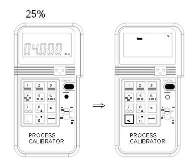
19 4d. Enter a Negative Temperatura The resolution of temperature is 1 degree, so the decimal point is used a minus "-" sign. To enter a negative temperature, press the "-" button first. 5. % input in the ma, mv, V functions In the ma, mv, or V function, users can enter percentage. To enter percentage (%) 1. Users press the shift button first, then SHIFT symbol will be displayed in the LCD. 2 Press % button first, then press the number (no decimal number, the % resolution is 1%). 3 After percentage is entered, the percentage will be displayed in the upper LCD, and the corresponding value will be displayed in the lower LCD. 4. The corresponding value is calculated based upon the range selected. 4-20mA: 1% = 0.16mA 0-20mA: 1% = 0.2mA 0-24mA: 1% = 0.24mA 0-100mV: 1% = 1mV 0-1V: 1% = 0.01V 0-12V: 1% = 0.12V 5. To exit the percentage-input mode, press the SHIFT button again. 6. After the SHIFT button is pressed, the upper LCD will become blank, while the lower LCD retains its last value. 19
20 20

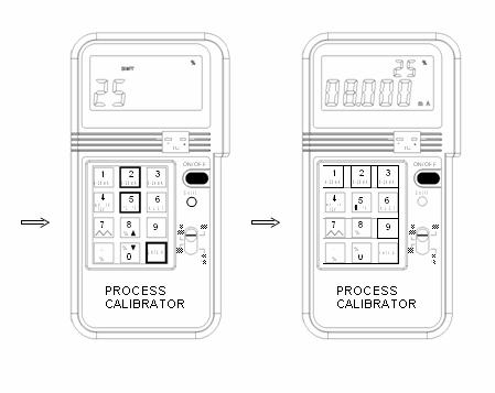
21 6. Easy Step in the ma, mv, and V Functions While the percentage is entered and calibrator is still in the SHIFT mode, users can step up or down by the percentage entered. The maximum percentage is 100% while the minimum percentage is 0%. If the next step up or down exceeds the maximum or minimum percentage, the percentage will stay in the previous step. Example 1: Step Up and Down(25%): 25% -> 50% -> 75% -> 100% -> 75% -> 50% -> 25% -> 0% -> 25% Example 2: Step Up and Down(30%): 30% -> 60% -> 90% -> 60% -> 30% -> 0% -> 30% 21


22 7. Auto Ramp in the ma, mv, and V functions In the ma, mv, and V function, auto ramp function is available to the users. To start the ramp function: 1. Press the SHIFT button to enter the SHIFT mode. 2. Press the NUMBER 7 key to Stara 3. Ramp function increment from 0% to 100%, then decrements from 100% to 0% repeatedly. The resolution of each step is 1% (with respect the range selected) at an interval of 0.08 seconds. So it takes 8 seconds to ramp from 0 to 100%. 4. To temporarily stop the ramp function, press the NUMBER 7 key, and the output will stay at the value when the NUMBER 7 key is pressed. These features will facilitate the checking of trigger point of tested device, such as valve controller. 5. To restart again, press the NUMBER 7 button again. 6. To return to the regular output mode, press the SHIFT button again when ramp function is stopped. 22
23 Note: Do not press any button while the calibrator is performing the ramp function (except NUMBER 7 button to stop the ramp function). 23
24 8. How to Get Negative Output If negative output (ma, mv, or V) is needed, users can achieve it by interchange the connection of test leads. 24
25 III. Electrical Specification (23 ºC ± 5 ºC, 3 minutes after power is on) ma DC Current (1KΩ Max. Load, 24V Loop Supply) Beeper warning when output is open and specified current output > 1mA mv, V DC Voltage (1mA Supply Current) Beeper warning when output is short and specified voltage output > 10mV K, J, E, T type Thermocouples( 1C,1F Resolution,1KΩ load Min. ) 25
26 Frequency (1-125Hz, 1KΩ Load Min.) Range Resolution Accuracy Hz 1 Hz ± 0.04Hz Available Frequencies ( Hz, Accuracy ± 0.01% ± 0.04Hz, 1KΩ Load Min):
27
28
29 General Specification: Battery Type: 9V Alkaline Battery Power Consumption: 60mA - 180mA (depends on output) Low battery: 5.5V at 150mA Load Display: 4 and 5 Digits Operating Temperature: 0 to 50 ºC ( 32 to 122 ºF) Operating Humidity: Less than 85% relative Storage Temperature: -20 to 60 ºC (-4 to 140 ºF) Storage Humidity: Less than 85% relative Dimension: 88 x 168 x 26 mm (3.46" x 6.61" x 1.03") Weight: 330 g / oz Accessories: Carrying case x 1 Users Manual x 1 K type thermocouple connector External Battery Pack Holder 1.5V AA Batteries x 6 Test leads with Alligator clip x 1 IV. Use the AC adapter If long term usage of the calibrator is required, AC adapter can be used. The 12V AC terminal is located in the back of the calibrator. The voltage should be regulated between 9 to 15V. 29
30 V. Use External Battery Pack An external battery pack is included for a longer period usage. The external battery pack needs to be packed with 6 pieces of 1.5 volts AA batteries. To use the external battery pack, plug into the AC terminals located in the back of the calibrator. VI. Battery Replacement When the low battery symbol is displayed on LCD, follow the following procedures to replace the battery. 1 Turn off the calibrator by pushing the On/Off button. 2 Remove the screw of the battery compartment cover and remove the battery compartment cover. 3 Replace the old 9V battery with a new alkaline 9V battery. 4 Replace the battery compartment cover and fasten the screw. Note: In the ma, mv, V, 0 ºC, and ºF functions, status of low battery is detected. While in the Hz function, status of low battery is not detected. 30
31 In this direction will find a vision of the measurement technique: NOTE: "This instrument doesn t have ATEX protection, so it should not be used in potentially explosive atmospheres (powder, flammable gases)." 31
Multifunction Calibrator
 Multifunction Calibrator Model CL TC - - - C V _ TECPEL CO., LTD. Features:. - (KΩ load, V Loop Supply). -.,-.V, -.V. K, J, E, T Thermocouple ( C and ). Frequency -.. Basic Accuracy. Easy Key-pad Operation.
I. PANEL DESCRIPTION... 1
 Table of Contents I. PANEL DESCRIPTION... 1 II. OPERATING INSTRUCTION... 7 1. MA OUTPUT... 7 1A. GENERAL OPERATION 4-20MA... 7 1B. SELECT 0-20MA OR 0-24MA... 8 1C. ENTER A VALUE LESS THAN 1... 9 2. % (PERCENTAGE)
Manual Compact Scale / Balance PCE-BS 300 / 3000
 www.pce-industrial-needs.com Tursdale Technical Services Ltd Unit N12B Tursdale Business Park Co. Durham DH6 5PG United Kingdom Phone: +44 ( 0 ) 191 377 3398 Fax: +44 ( 0 ) 191 377 3357 info@tursdaletechnicalservices.co.uk
2 in1 LAN Tester & Multimeter. Model: PCE-LT 1
 www.pce-industrial-needs.com Tursdale Technical Services Ltd Unit N12B Tursdale Business Park Co. Durham DH6 5PG United Kingdom Phone: +44 ( 0 ) 191 377 3398 Fax: +44 ( 0 ) 191 377 3357 info@tursdaletechnicalservices.co.uk
 www.pce-industrial-needs.com Tursdale Technical Services Ltd Unit N12B Tursdale Business Park Co. Durham DH6 5PG United Kingdom Phone: +44 ( 0 ) 191 377 3398 Fax: +44 ( 0 ) 191 377 3357 info@tursdaletechnicalservices.co.uk
The Specification of Hot Wire Anemometer Manual PCE-423
 www.industrial-needs.com Tursdale Technical Services Ltd Unit N12B Tursdale Business Park Co. Durham DH6 5PG United Kingdom Phone: +44 ( 0 ) 191 377 3398 Fax: +44 ( 0 ) 191 377 3357 info@tursdaletechnicalservices.co.uk
Manual SOUND LEVEL METER PCE-322 A
 www.pce-industrial-needs.com Tursdale Technical Services Ltd Unit N12B Tursdale Business Park Co. Durham DH6 5PG United Kingdom Phone: +44 ( 0 ) 191 377 3398 Fax: +44 ( 0 ) 191 377 3357 info@tursdaletechnicalservices.co.uk
WARNING: Do not use the thermometer/data logger before you read the users manual and the following instructions.
 55 This unit passes the following tests EN 61326-1:2006 (CISPR11,IEC/EN 61000-3-2:2006, IEC/EN 61000-3-3: 1995+A1 :2001+A2:2005 IEC/EN 61000-4-2/-3/-5/-6/-11) WARNING: Do not use the thermometer/data logger
 PCE Instruments UK Ltd Units 12/13 Southpoint Business Park Ensign Way, Southhampton Hampshire United Kingdom, SO31 4RF Phone +44(0) 2380 98703 0 Fax +44(0) 2380 98703 9 info@industrial-needs.com Thermometer
RH/Temperature SD Card Datalogger. Instruction Manual
 RH/Temperature SD Card Datalogger 800021 Instruction Manual RH/Temperature SD Card Datalogger 800021 Copyright 2010 by Sper Scientific ALL RIGHTS RESERVED Printed in the USA The contents of this manual
Visible Light SD Card Datalogger
 Visible Light SD Card Datalogger 850007 Instruction Manual Eastern Energy Co., Ltd. 40/4 Vitoondumri Rd., Banbueng Banbueng, Chonburi, Thailand Tel: 66-3844-6117 sale@ete.co.th www.eastern-energy.com Visible
RS Stock No Instruction Manual RS Input Data Logging Thermometer
 RS Stock No. 730-0458 Instruction Manual RS-1384 4 Input Data Logging Thermometer EN FR IT DE ES TABLE OF CONTENTS / EN TITLE TABLE OF CONTENTS PAGE 1. INTRODUCTION FEATURE... 1 2. SPECIFICATIONS... 2
Anemometer SD Card Datalogger. Instruction Manual
 Anemometer SD Card Datalogger 850023 Instruction Manual 1 Anemometer SD Card Datalogger 850023 Copyright 2010 by Sper Scientific ALL RIGHTS RESERVED Printed in the USA The contents of this manual may not
Manual PCE-MM200
 www.pce-industrial-needs.com Tursdale Technical Services Ltd Unit N12B Tursdale Business Park Co. Durham DH6 5PG United Kingdom Phone: +44 ( 0 ) 191 377 3398 Fax: +44 ( 0 ) 191 377 3357 info@tursdaletechnicalservices.co.uk
Manual Sound level indicator PCE-353
 PCE Americas Inc. 711 Commerce Way Suite 8 Jupiter FL-33458 USA From outside US: +1 Tel: (561) 320-9162 Fax: (561) 320-9176 info@pce-americas.com PCE Instruments UK Ltd. Units 12/13 Southpoint Business
Manual Digital Thermometer PCE-T 390
 PCE Americas Inc. 711 Commerce Way Suite 8 Jupiter FL-33458 USA From outside US: +1 Tel: (561) 320-9162 Fax: (561) 320-9176 info@pce-americas.com PCE Instruments UK Ltd. Units 12/13 Southpoint Business
Model R5010. TRMS Digital Multimeter. Instruction Manual
 INSTRUMENTS Model R5010 TRMS Digital Multimeter Instruction Manual Table of Contents Safety...3-4 IEC1010 Overvoltage Installation Category... 3 Warnings... 4 Features... 5 Specifications...5-8 Instrument
Datalogging Hot Wire CFM Anemometer
 Datalogging Hot Wire CFM Anemometer 840002 Instruction Manual SPER SCIENTIFIC LTD. TABLE OF CONTENTS 1. INTRODUCTION... 3 2. PANEL DESCRIPTION... 4-5 3. MEASURING PROCEDURE... 5 3-A Air Velocity and Ambient
Mini Digital Multimeter
 User's Guide Mini Digital Multimeter Model MN15 99 Washington Street Melrose, MA 02176 Phone 781-665-1400 Toll Free 1-800-517-8431 Visit us at www.testequipmentdepot.com Back to the Extech MN15/MN16 Series
Model R5005. Instruction Manual. True RMS Industrial Multimeter. reedinstruments. www. com
 Model R5005 True RMS Industrial Multimeter Instruction Manual reedinstruments com Table of Contents Safety... 4 Features... 5 Specifications...5-6 Instrument Description...7-8 Operating Instructions...9-13
ETHOS Auto Ranging Digital Multimeter
 ETHOS 5020 Auto Ranging Digital Multimeter 1 1. SAFETY INFORMATION SAFETY SYMBOLS Warning! Dangerous Voltage (Risk of electric shock). Caution! Refer to the user s manual before using this Meter. Double
DIGITAL PANEL THERMOMETER
 Love Controls DIGITAL PANEL THERMOMETER LCI108-1x LCI108J-1x INSTRUCTION MANUAL EDITION: January 2001 INTRODUCTION TO THE LOVE CONTROLS LCI108 SERIES This manual does not constitute a formal agreement.
PIECAL 322 Automated Thermocouple Calibrator Operating Instructions. Product Description. Practical Instrument Electronics
 PIECAL 322 Automated Thermocouple Calibrator Operating Instructions Product Description Easy to use With the PIECAL 322-1 you can check & calibrate all your thermocouple instruments and measure thermocouple
12-Channel Thermocouple Datalogger
 User Manual 12-Channel Thermocouple Datalogger Model TM500 Additional User Manual Translations available at www.extech.com Introduction Congratulations on your purchase of the Extech TM500 Thermometer,
600 g x 0.02 g DIGITAL BALANCE
 600 g x 0.02 g DIGITAL BALANCE Model : GM-600P Your purchase of this DIGITAL BALANCE marks a step forward for you into the field of precision measurement. Although this DIGITAL BALANCE is a complex and
Model INSTRUCTION MANUAL DIGITAL MULTIMETER
 Model 57040 INSTRUCTION MANUAL DIGITAL MULTIMETER SAFETY INFORMATION This multimeter has been designed according to IEC 1010 concerning electronic measuring instruments with an overvoltage category (CAT
DIGITAL PANEL THERMOMETER
 Love Controls DIGITAL PANEL THERMOMETER LCI108-2x LCI108J-2x INSTRUCTIONS MANUAL EDITION: February 2001 INTRODUCTION TO THE LOVE CONTROLS LCI108 SERIES This manual does not constitute a formal agreement.
User's Guide. 3 Channel Datalogging Thermometer Model SD200
 User's Guide 3 Channel Datalogging Thermometer Model SD200 Introduction Congratulations on your purchase of the Extech SD200 3-Channel Temperature Datalogger. This meter displays and stores temperature
W Warning To avoid electrical shock, remove test leads and any input signals from the Model 707 Loop Calibrator before opening the case.
 Model 707 Loop Calibrator W Warning To avoid electrical shock, remove test leads and any input signals from the Model 707 Loop Calibrator before opening the case. WCaution The Model 707 Loop Calibrator
4-Channel Datalogging Thermometer
 4-Channel Datalogging Thermometer 800024 4-Channel Datalogging Thermometer - 800024 Copyright 2015 by Sper Scientific ALL RIGHTS RESERVED. Printed in the USA The contents of this manual may not be reproduced
Manual Sound level meter PCE-353
 www.pce-industrial-needs.com Tursdale Technical Services Ltd Unit N12B Tursdale Business Park Co. Durham DH6 5PG United Kingdom Phone: +44 ( 0 ) 191 377 3398 Fax: +44 ( 0 ) 191 377 3357 info@tursdaletechnicalservices.co.uk
4-Channel Thermometer
 4-Channel Thermometer 800023 4-Channel Thermometer - 800023 Copyright 2015 by Sper Scientific ALL RIGHTS RESERVED. Printed in the USA The contents of this manual may not be reproduced or transmitted in
User's Guide. Digital Multimeter. Model MN42
 User's Guide Digital Multimeter Model MN42 Introduction Congratulations on your purchase of the Extech MN42 MultiMeter. The MN42 offers AC/DC Voltage, DC Current, and Resistance testing. Proper use and
Manual Oscilloscope (Scope-Meter)
") www.pce-industrial-needs.com Tursdale Technical Services Ltd Unit N12B Tursdale Business Park Co. Durham DH6 5PG United Kingdom Phone: +44 ( 0 ) 191 377 3398 Fax: +44 ( 0 ) 191 377 3357 info@tursdaletechnicalservices.co.uk
www.pce-industrial-needs.com Tursdale Technical Services Ltd Unit N12B Tursdale Business Park Co. Durham DH6 5PG United Kingdom Phone: +44 ( 0 ) 191 377 3398 Fax: +44 ( 0 ) 191 377 3357 info@tursdaletechnicalservices.co.uk
Model R5010. Instruction Manual. TRMS Digital Multimeter. reedinstruments www.
 Model R5010 TRMS Digital Multimeter Instruction Manual reedinstruments www com Table of Contents Safety...3-4 Features... 5 Specifications...5-8 Instrument Description...8-9 Operating Instructions...10-16
INDICATOR FOR PROCESS CONTROL. Love Controls. LCI108J-0x INSTRUCTION MANUAL. EDITION: January Valid for models with software version P-1
 Love Controls INDICATOR FOR PROCESS CONTROL LCI108-0x LCI108J-0x INSTRUCTION MANUAL EDITION: January 2001 Valid for models with software version P-1 INTRODUCTION TO THE LOVE CONTROLS LCI108 SERIES This
CONTENTS 1. SAFETY INFORMATION SPECIFICATION PARTS & CONTROLS General Specification Electrical Specification...
 Title CONTENTS page 1. SAFETY INFORMATION... 1 2. SPECIFICATION... 2 2-1 General Specification... 2 2-2 Electrical Specification... 5 3. PARTS & CONTROLS... 6 3-1 The Name of Each Parts and Positions...
S-14 S-14. Compact Digital Multimeter. Compact Digital Multimeter
 S-14 Compact Digital Multimeter S-14 Compact Digital Multimeter SAFETY INFORMATION The following safety information must be observed to insure maximum personal safety during the operation at this meter
Thermocouple Calibrator
 USER GUIDE 99 Washington Street Melrose, MA 02176 Phone 781-665-1400 Toll Free 1-800-517-8431 Visit us at www.testequipmentdepot.com Thermocouple Calibrator Model PRC20 Introduction Thank you for selecting
Mini Digital Multimeter Model MN15. User's Guide
 Mini Digital Multimeter Model MN15 User's Guide Introduction Congratulations on your purchase of the Extech MN15 MultiMeter. The MN15 offers AC/DC Voltage, AC/DC Current, Resistance, Diode, and Continuity
Model A Current / Voltage Calibrator. User's Guide
 Model 412355A Current / Voltage Calibrator User's Guide Introduction Congratulations on your purchase of the Extech Current/Voltage Calibrator. The Model 412355A can measure and source current and voltage.
Hygro-Thermometer / Datalogger
 USER GUIDE Hygro-Thermometer / Datalogger Model SDL500 Introduction Congratulations on your purchase of the Extech SDL500 Hygro-Thermometer, an SD Logger Series meter. This meter displays and stores Temperature
Model: Pro93 TRUE RMS LEAKAGE CURRENT TESTER
 Model: Pro93 TRUE RMS LEAKAGE CURRENT TESTER CONTENTS TITLE PAGE I. Safety Information.......1 Environmental Conditions... 1 Explanation of Symbols..... 1 II. Specification..... 2 General Specification...
R5050. Model. Instruction Manual. TRMS AC/DC Clamp Meter. reedinstruments. www. com
 Model R5050 TRMS AC/DC Clamp Meter Instruction Manual reedinstruments com Table of Contents Safety... 3 Features... 4 Specifications...4-6 Instrument Description...7-8 Measurement Procedures...9-12 Battery
User's Guide. MiniTec TM Series Model MN25 MultiMeter
 User's Guide MiniTec TM Series Model MN25 MultiMeter Warranty EXTECH INSTRUMENTS CORPORATION warrants this instrument to be free of defects in parts and workmanship for one year from date of shipment (a
Mini Digital Multimeter
 User's Guide Mini Digital Multimeter Model MN15 Introduction Congratulations on your purchase of the Extech MN15 MultiMeter. The MN15 offers AC/DC Voltage, AC/DC Current, Resistance, Diode, and Continuity
Copra Moisture Tester. Operating Manual
 Copra Moisture Tester HX-120 Operating Manual Copra Moisture Tester Safety Precautions If the safety precautions for the copra moisture tester are not observed, injuries or damage to property may result.
Mini Digital Multimeter
 User Manual Mini Digital Multimeter Model MN15A Additional User Manual Translations available at www.extech.com Introduction Congratulations on your purchase of the Extech MN15A MultiMeter. The MN15A offers
OPERATION MANUAL. Green power, Hybrid power Auto range, A/C weighting SOUND LEVEL METER. Model : SL-4113G. Your purchase of this
 Green power, Hybrid power Auto range, A/C weighting SOUND LEVEL METER Model : SL-4113G Your purchase of this SOUND LEVEL METER marks a step forward for you into the field of precision measurement. Although
4-Channel Thermometer / Datalogger
 User's Guide 4-Channel Thermometer / Datalogger RTD and Thermocouple Inputs Model SDL200 Introduction Congratulations on your purchase of the Extech SDL200 Thermometer, an SD Logger Series meter. This
EDX-10 Series. Compact Recording System
 3-49 EDX-10 Series Compact Recording System Compact, lightweight, with a simple configuration, all channels synchronous 20 khz high-speed sampling (For 4 channels) Control Unit EDX-10B A unit controls
RS Stock No Instruction Manual RS Input Data Logging Thermometer
 RS Stock No. 730-0458 Instruction Manual RS-1384 4 Input Data Logging Thermometer EN FR IT DE ES TABLE OF CONTENTS / EN TITLE TABLE OF CONTENTS PAGE 1. INTRODUCTION FEATURE... 1 2. SPECIFICATIONS... 2
Autoranging Mini Multimeter
 User Manual Autoranging Mini Multimeter Model MN16A Additional User Manual Translations available at www.extech.com Introduction Congratulations on your purchase of the Extech MN16A Autoranging Multimeter.
HANDHELD CALIBRATOR-MULTIMETER OC502-t
 OC502-t_GBM_21311 HANDHELD CALIBRATOR-MULTIMETER OC502-t Owner s Manual ORBIT CONTROLS AG Zürcherstrasse 137 CH-8952 Schlieren/ZH Tel: + 41 44 730 2753 Fax: + 41 44 730 2783 info@orbitcontrols.ch www.orbitcontrols.ch
OPERATION MANUAL. separate probe, RS-232 SOUND LEVEL METER. Model : SL-4013
 separate probe, RS-232 SOUND LEVEL METER Model : SL-4013 Your purchase of this SOUND LEVEL METER marks a step forward for you into the field of precision measurement. Although this SOUND LEVEL METER is
EDX-10 Series. Compact Recording System
 3-51 EDX-10 Series Compact Recording System Compact & lightweight, with a simple configuration, all channels synchronous 20 khz high-speed sampling (For 4 channels) Control Unit EDX-10B A unit controls
3 Channel Datalogging Thermometer
 USER MANUAL 3 Channel Datalogging Thermometer Model SD200 Introduction Congratulations on your purchase of the Extech SD200 3-Channel Temperature Datalogger. This meter displays and stores temperature
Datalogging Conductivity/ TDS Meter. Instruction Manual
 Datalogging Conductivity/ TDS Meter 850039 Instruction Manual 1 TABLE OF CONTENTS 1. INTRODUCTION...3 2. PANEL DESCRIPTION...4 3. MEASURING PROCEDURE...5 3-A General Measurement...5 3-B Auto and Manual
OPERATOR S INSTRUCTION MANUAL DIGITAL MULTIMETER
 OPERATOR S INSTRUCTION MANUAL DIGITAL MULTIMETER SAFETY INFORMATION This multimeter has been designed according to IEC 1010 concerning electronic measuring instruments with an overvoltage category (CATⅡ)
TC41-Thermocouple Thermometers User Manual
 TC41-Thermocouple Thermometers User Manual Product Registration cs@perfect-prime.com Product Introduction This thermometer can be used to measure up to 4 different temperatures simultaneously, and with
 PCE Americas Inc. PCE Instruments UK Ltd. 711 Commerce Way Units 12/13, Southpoint Business Park Suite 8 Ensign Way Jupiter, FL 33458 Hampshire / Southampton USA United Kingdom, SO31 4RF Phone: 561-320-9162
PIECAL 520B & 521B Thermocouple Source Operating Instructions
 PIECAL 520B & 521B Thermocouple Source Operating Instructions (Shown without optional boot) Product Description (Shown with optional boot) Easy to use With the PIECAL 520B/521B you can check & calibrate
Type K/J Thermometers
 Type K/J Thermometers 800005 CONTENTS INTRODUCTION....2 FRONT PANEL DESCRIPTION...3 LCD DISPLAY....4 OPERATION INSTRUCTION...5 Power Up....5 Connecting the Thermocouples....5 Selecting Temperature Scale....5
AC/DC MAGNETIC METER OPERATION MANUAL. Model : PCE-MFM G ( Gauss), mt ( milli Tesla ), USB/RS232. Your purchase of this
, mt ( milli Tesla ), USB/RS232. Your purchase of this") G ( Gauss), mt ( milli Tesla ), USB/RS232 AC/DC MAGNETIC METER Model : PCE-MFM 3000 Your purchase of this AC/DC MAGNETIC METER marks a step forward for you into the field of precision measurement. Although
G ( Gauss), mt ( milli Tesla ), USB/RS232 AC/DC MAGNETIC METER Model : PCE-MFM 3000 Your purchase of this AC/DC MAGNETIC METER marks a step forward for you into the field of precision measurement. Although
Operation Manual for Multifunctional Data Logger. HUATO Electronic Co., LTD.
 Operation Manual for Multifunctional Data Logger HUATO Electronic Co., LTD. Contents Contents...2 1. Introduction...1 1.1 Features...1 1.2 Structure for S210 multifunctional data logger...1 1.3 LCD symbols
HDT-318 Thermo-Hygrometer with Data Logger. (Air Humidity/Temperature) Instruction Manual
 Instruction Manual") HDT-318 Thermo-Hygrometer with Data Logger (Air Humidity/Temperature) Instruction Manual CONTENTS 1. SAFETY INFORMATION... 2 2. GENERAL DESCRIPTION... 2 3. FEATURES... 2 4. SPECIFICATIONS... 3 5. SYMBOL
HDT-318 Thermo-Hygrometer with Data Logger (Air Humidity/Temperature) Instruction Manual CONTENTS 1. SAFETY INFORMATION... 2 2. GENERAL DESCRIPTION... 2 3. FEATURES... 2 4. SPECIFICATIONS... 3 5. SYMBOL
SOUND LEVEL METER OPERATION MANUAL. Model : SL Your purchase of this
 SOUND LEVEL METER Model : SL-4012 Your purchase of this SOUND LEVEL METER marks a step forward for you into the field of precision measurement. Although this METER is a complex and delicate instrument,
Model A Mini AC/DC Clamp Meter. User's Guide
 Model 380950 80A Mini AC/DC Clamp Meter User's Guide Introduction Congratulations on your purchase of the Extech 80A Mini AC/DC Clamp Meter. The Model 380950 measures AC/DC Current, AC/DC Voltage, Resistance,
AC/DC MAGNETIC METER OPERATION MANUAL. Model : MG G ( Gauss), mt ( milli Tesla ), USB/RS232. Your purchase of this
, mt ( milli Tesla ), USB/RS232. Your purchase of this") G ( Gauss), mt ( milli Tesla ), USB/RS232 AC/DC MAGNETIC METER Model : MG-3002 Your purchase of this AC/DC MAGNETIC METER marks a step forward for you into the field of precision measurement. Although
G ( Gauss), mt ( milli Tesla ), USB/RS232 AC/DC MAGNETIC METER Model : MG-3002 Your purchase of this AC/DC MAGNETIC METER marks a step forward for you into the field of precision measurement. Although
Manual Handheld Rotation Meter PCE-155
 PCE Americas Inc. 711 Commerce Way Suite 8 Jupiter FL-33458 USA From Outside US: +1 Tel: (561) 320-9162 Fax: (561) 320-9176 info@pce-americas.com www.pce-instruments.com/us PCE Instruments UK Ltd. Units
UWE-1707 SERIES CONTENTS OPERATION MANUAL ELECTRONIC WEIGHING INDICATOR 1. SPECIFICATIONS 2. INSTALLATION
 UWE-1707 SERIES CONTENTS ELECTRONIC WEIGHING INDICATOR OPERATION MANUAL 1. SPECIFICATIONS PLEASE READ THIS MANUAL VERY CAREFULLY BEFORE ATTEMPT TO OPERATE THE SCALE 2. INSTALLATION 3. ROUTINE OPERATION
Users Manual. Operating and Installation Instructions Buffalo River Black Dimaond. Model:ECSL-0601A Electronic Combination Controller
 Users Manual Operating and Installation Instructions Buffalo River Black Dimaond Model:ECSL-0601A Electronic Combination Controller b. If no user code exists, push button 1, One Beep sounds, which prompts
GE Infrastructure Sensing. Druck DPI 832. Electrical loop calibrator User manual - K393
 GE Infrastructure Sensing Druck DPI 832 Electrical loop calibrator User manual - K393 A1 B1 10 1 A 2 9 A 3 8 2 3 7 6 11 4 5 B1 12 A2 13 15 14 A3 19 18 17 16 27 20 21 22 23 26 24 25 K393 Issue 1 Table of
BENCH-TOP DIGITAL MULTIMETER INSTRUCTION MANUAL
 BENCH-TOP DIGITAL MULTIMETER INSTRUCTION MANUAL SK-4033 / SK-4035 Thank you for purchasing KAISE MODEL SK-4033/4035 BENCH-TOP DIGITAL MULTIMETERS. To obtain the maximum performance of this instrument,
USER GUIDE. Dual Input True RMS AC Voltage/Current Datalogger. Model DL160
 USER GUIDE Dual Input True RMS AC Voltage/Current Datalogger Model DL160 Introduction Congratulations on your purchase of this Dual Input Voltage / Current datalogger. With this meter, you can monitor
SBS-S SERIES DC LOAD BANK USER MANUAL Rev
 SBS-S SERIES DC LOAD BANK USER MANUAL Rev. 2.0 12-14 Test Equipment Depot - 800.517.8431-99 Washington Street Melrose, MA 02176 TestEquipmentDepot.com Contents OPERATING INSTRUCTIONS 1. Environment Requirement
OPERATING INSTRUCTION
 OPERATING INSTRUCTION AUTORANGING MULTIMETER MAX Ω F C 10A MAX every 15 min. COM V SAFETY INFORMATION The following safety information must be observed to insure maximum personal safety during the operation
User Guide True RMS Multimeter Extech EX205T
 User Guide Extech EX205T True RMS Digital Multimeter Extech EX210T True RMS Digital Multimeter IR True RMS Multimeter Extech EX205T Introduction Thank you for selecting the Extech EX205T True RMS Auto-ranging
Model R2400. Instruction Manual. Digital Thermocouple Thermometer. reedinstruments
 Model R2400 Digital Thermocouple Thermometer Instruction Manual reedinstruments com 1-877-849-2127 info@reedinstruments.com.reedinstruments.com Table of Contents Safety... 2 Features... 3 Specifications...3-4
MMD7003 USER S MANUAL. DIGITAL and LED PRECISION MOISTURE METER
 MMD7003 USER S MANUAL DIGITAL and LED PRECISION MOISTURE METER INTRODUCTION: Congratulations on your purchase of this Digital and LED Precision Moisture Meter. This unit detects moisture in wood and other
DIGITAL MULTIMETER 4 1/2 digits, True RMS Model : DM-9027T
 DIGITAL MULTIMETER 4 1/2 digits, True RMS Model : DM-9027T Caution Symbol Caution : * Risk of electric shock! Caution : * Do not apply the overload voltage, current to the input terminal! * Remove test
User's Guide. Datalogging Hygro-Thermometer Model SD500
 User's Guide Datalogging Hygro-Thermometer Model SD500 Introduction Congratulations on your purchase of the Extech SD500 Temperature/Humidity Datalogger. This meter measures, displays, and stores temperature
OPERATION MANUAL. auto range + type K Temp. optional Humidity, Light, Anemometer SOUND LEVEL METER Model : SL-4112
 auto range + type K Temp. optional Humidity, Light, Anemometer SOUND LEVEL METER Model : SL-4112 Your purchase of this SOUND LEVEL METER marks a step forward for you into the field of precision measurement.
Torque Meter. Instruction Manual
 Torque Meter 840062 Instruction Manual CONTENTS I. Introduction... 4 II. Meter Description... 4 III. Operating Instructions 1. Measuring Procedures... 5 2. Automatic Shut Off... 6 3. Battery Replacement...
LED LIGHT METER OPERATION MANUAL. Model : LX-1148SD. SD card real time Data Recorder 10 Light Source select, Auto range 0 to 50,000 LUX
 SD card real time Data Recorder 10 Light Source select, Auto range 0 to 50,000 LUX LED LIGHT METER Model : LX-1148SD Your purchase of this LED LIGHT METER with SD CARD DATA LOGGER marks a step forward
 PCE Instruments UK Ltd Units 12/13 Southpoint Business Park Ensign Way, Southhampton Hampshire United Kingdom, SO31 4RF Phone +44(0) 2380 98703 0 Fax +44(0) 2380 98703 9 info@industrial-needs.com PCE-PTR
Stand-Alone, Low-Cost Data Loggers and Accessories. USB-500/600 Series Comparison Chart
 Stand-Alone, Low-Cost Data Loggers and Accessories Features Stand-alone remote data loggers and portable logger assistant Measure temperature, humidity, voltage, current, or event/state change 1 or 2 channels
Model A Current Calibrator. User Guide
 Model 412300A Current Calibrator User Guide Introduction Congratulations on your purchase of the Extech Current Calibrator Model 412300A. The 412300A can measure/source current and can also power a current
HI HI HI HI Portable Microprocessor Thermistor Thermometers
 1 2 Instruction Manual HI 93501 - HI 93502 HI 93503 - HI 93510 Portable Microprocessor Thermistor Thermometers LO HI CLEAR F HOLD ins rum n s ON OFF Dear Customer, Thank you for choosing a Hanna product.
INSTRUCTION MANUAL DIGITAL MULTIMETER KEW 1051/1052
 INSTRUCTION MANUAL DIGITAL MULTIMETER KEW 1051/1052 Thank you for purchasing our Model KEW1051, KEW1052 Digital Multimeter. This instruction manual describes the specifications and handling precaution
PM-100 SERIES. Operation Guide. Power Meter V
 PM-100 SERIES Power Meter Operation Guide V5.27.16 Contents 1 Introduction...2 2 Warranty...2 3 Safety Information...3 4 Preparing for Operation...3 4.1 Unpacking the instrument...3 4.2 Discharged batteries...3
1. Introduction 2. Specifications 3. Symbol Definition and Button Location 4. Operation Instructions 5. Temperature Measurement 6.
 CONTENTS TITLE PAGE 1. Introduction.. 1 2. Specifications... 1 3. Symbol Definition and Button Location... 2 4. Operation Instructions.... 3 4.1 Power-Up...3 4.2 Connection of the Temperature Probe...
12 channels TEMPERATURE RECORDER Model : BTM-4208SD
 SD Card real time data recorder 12 channels TEMPERATURE RECORDER Model : BTM-4208SD Your purchase of this 12 c h a n n e l s T E M P E R A T U R E RECORDER with SD CARD DATALOGGER marks a step forward
Accsense Wireless System. Temperature Monitor
 Accsense Wireless System Temperature Monitor Contents 1. Installing the B1-06 Gateway...2 2. Installing the Pods...3 3. Wiring the Pods...5 Version 1 - August 2010 29975 Page 1 1. Installing the B1-06
Autoranging True RMS Multimeter User Manual
 Autoranging True RMS Multimeter User Manual Please read this manual before switching the unit on. Important safety information inside. Contents Page 1. Safety Information... 4 2. Safety Symbols... 5 3.
CM-220 True RMS AC CLAMP METER INSTRUCTION MANUAL
 CM-220 True RMS AC CLAMP METER INSTRUCTION MANUAL Safety International Safety Symbols This symbol, adjacent to another symbol or terminal, indicates the user must refer to the manual for further information.
Datalogging Hygro-Thermometer
 USER GUIDE Datalogging Hygro-Thermometer Model SD500 Extech SD500 Humidity Temperature Datalogger Introduction Congratulations on your purchase of the Extech SD500 Temperature/Humidity Datalogger. This
HI-POT TESTER. User s Manual
 HI-POT TESTER 7620 User s Manual Contents 1. Before Use... 1.1Electric Shock Avoidance... 4 1.2 Grounding... 4 1.3 AC Power Supply... 4 1.4 Connecting Test Leads... 4 1.5 Warm Up... 4 1.6 External Control...
99 Washington Street Melrose, MA Fax TestEquipmentDepot.com. Handy Calibrators
 99 Washington Street Melrose, MA 02176 Fax 7816650780 TestEquipmentDepot.com Handy Calibrators / Voltage/Current Calibrator Temperature Calibrator Both signal source and measurement functions Simple operation,
Owner's Manual. True RMS Multimeter. Model No Safety Operation Maintenance Español
 Owner's Manual True RMS Multimeter Model No. 82023 CAUTION: Read, understand and follow Safety Rules and Operating Instructions in this manual before using this product. Safety Operation Maintenance Español