Electronic Product Catalogue
|
|
|
- Lindsay Peters
- 5 years ago
- Views:
Transcription

727-132")
59-03-52")
249-28-31")
278-03-48 Вологда")
204-51-73")
384-55-89 Иваново")
26-03-58 Казань")

92-23-67 Кемерово")
68-02-04")
203-40-90")
204-63-61 Курск")
52-20-81")
55-03-13 Москва")
59-64-93")
20-53-41 Нижний")


44-53-42 Оренбург")

1 Electronic Product Catalogue Архангельск (8182) Астана +7(7172) Белгород (4722) Брянск (4832) Владивосток (423) Волгоград (844) Вологда (8172) Воронеж (473) Екатеринбург (343) Иваново (4932) Ижевск (3412) Казань (843) Калининград (4012) Калуга (4842) Кемерово (3842) Киров (8332) Краснодар (861) Красноярск (391) Курск (4712) Липецк (4742) Магнитогорск (3519) Москва (495) Мурманск (8152) Набережные Челны (8552) Нижний Новгород (831) Новокузнецк (3843) Новосибирск (383) Орел (4862) Оренбург (3532) Пенза (8412) Пермь (342) Ростов-на-Дону (863) Рязань (4912) Самара (846) Санкт-Петербург (812) Саратов (845) Смоленск (4812) Сочи (862) Ставрополь (8652) Тверь (4822) Томск (3822) Тула (4872) Тюмень (3452) Ульяновск (8422) Уфа (347) Челябинск (351) Череповец (8202) Ярославль (4852) Единый адрес для всех регионов:


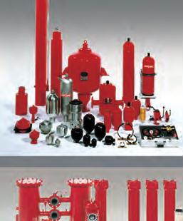
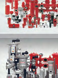
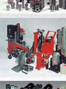
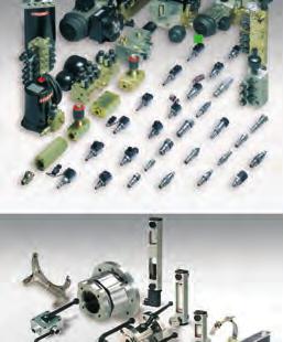
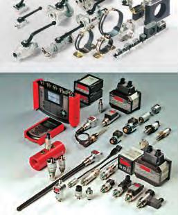
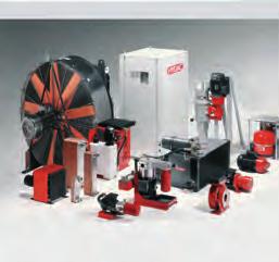
2 HYDAC Electronic HYDAC is best known for hydraulics, systems and fluid engineering. For over 50 years, HYDAC has been developing and manufacturing components and system solutions for specific applications in these fields. Over 30 years ago, inspired by its industry and application experience, HYDAC expanded its portfolio to include sensors, measuring instruments and electronic controls. The range of sensors includes products for the measurement of pressure, temperature, distance, position, level, flow volume, speed as well as contamination and oil condition. In addition to products for standard applications, the product portfolio also covers special applications such as potentially explosive atmospheres or applications with increased functional safety. Almost all these products are developed, manufactured and marketed by HYDAC ELECTRONIC. Suitability for the application is tested on HYDAC test rigs. As a Tier 1 automotive supplier, HYDAC ELECTRONIC is certified in accordance with the rigorous quality standard ISO/TS and therefore fulfils the very high requirements regarding product quality, production processes and continuous improvement processes. Our international sales network provides customers with worldwide product availability, expert advice and support. An extensive service package completes our offer. Computer simulation of a HYDAC pressure transmitter. Production and automatic function testing. Development and manufacturing plant in Saarbrücken-Gersweiler. HYDAC Servicenter, a complete package of services. Technical advice and training. Inspection Servicing Maintenance Installation Optimization E /
3 Note The information in this brochure relates to the operating conditions and applications described. For applications or operating conditions not described, please contact the relevant technical department. Subject to technical modifications. Page 1. Introduction 2 zindustries / Applications / Product Range Electronic pressure transmitters 8-33 for general applications zhda zhda zhda 4700 Approvals for shipping 13 zhda 4700 CANopen 15 zhda zhda 4400 Approvals for shipping 19 zhda zhda 4300 Approvals for shipping 23 zhda zhda 4100 Approvals for shipping 27 zhda zhda 7400 CANopen 31 zhda 3800 for Iron and Steel Works Applications Electronic pressure switches for general applications zeds zeds 3400 Menu navigation according to VDMA 41 zeds 3400 IO-Link 43 zeds zeds 3300 Menu navigation according to VDMA 49 zeds 3300 IO-Link 51 zeds zeds 3100 Menu navigation according to VDMA 57 zeds 3100 IO-Link 59 zeds zeds 300 Approvals for shipping 65 zeds zeds zeds zeds 4400 Programmable 73 zeds 4300 Programmable 75 zeds 820 IO-Link Pressure sensors with flush membrane for general applications zhda zhda zhda zhda zeds zeds Electronic temperature transmitters for general applications zets zets zets Electronic temperature switches for general applications zets 3200 pressure-resistant for inline installation 105 zets 3200 pressure-resistant for inline installation, menu navigation to VDMA 107 zets 3200 pressure-resistant for inline installation, IO-Link 109 zets 3200 for tank installation 111 zets 3200 for tank installation, menu navigation to VDMA 113 zets 3200 for tank installation, IO-Link 115 zets 3800 for separate temperature probe 117 zets 3800 for separate temperature probe, with menu navigation to VDMA 119 zets 3800 for separate temperature probe, IO-Link 121 zets 320 pressure-resistant for inline installation 123 zets 380 for separate temperature probe 125 zets 1700 for separate temperature probe 127 ztfp 100 (separate temperature probe) E /
4 Page 7 7. Sensors for distance and position for mobile and stationary applications zhlt 1000-R2 131 zhlt 2100-R1 133 zhlt 2500-F1 137 zhlt 2500-L2 141 zhls Level sensors for general applications zens zens 3000 IO-Link 153 zhns zhns zhnt Flow transmitters / flow switches for general applications zevs zevs zhfs zhfs zhft zhft Speed sensors for general applications zhss zhss zhss zhss zhss Sensors for applications with increased functional safety zhda 4700 for applications with increased functional safety 197 zhlt 1000 for applications with increased functional safety Sensors for potentially explosive atmospheres zhda 4700 ATEX, CSA, IECEx Flameproof enclosure 203 zeds 4400 ATEX, CSA, IECEx Flameproof enclosure, programmable 207 zets 4500 ATEX, CSA, IECEx Flameproof enclosure 211 zhda 4700 ATEX Intrinsically safe 215 zhda 4400 ATEX Intrinsically safe 219 zhda 4300 ATEX Intrinsically safe 223 zhda 4100 ATEX Intrinsically safe 227 zeds 4400 ATEX Intrinsically safe programmable 231 zeds 4300 ATEX Intrinsically safe programmable 235 zeds 4100 ATEX Intrinsically safe programmable 239 zhda 4700 CSA Intrinsically safe 243 zhda 4400 CSA Intrinsically safe 247 zhda 4300 CSA Intrinsically safe 251 zhda 4100 CSA Intrinsically safe 255 zhda 4700 IECEx Intrinsically safe 259 zhda 4400 IECEx Intrinsically safe 263 zhda 4300 IECEx Intrinsically safe 267 zhda 4100 IECEx Intrinsically safe 271 zhda 4700 with Flush Membrane ATEX Intrinsically safe 275 zhda 4400 with Flush Membrane ATEX Intrinsically safe 279 zhda 4300 with Flush Membrane ATEX Intrinsically safe 283 zhda 4700 with Flush Membrane IECEx Intrinsically safe 287 zhda 4400 with Flush Membrane IECEx Intrinsically safe 291 zhda 4300 with Flush Membrane IECEx Intrinsically safe 295 zhda 4700 with Flush Membrane ATEX, CSA, IECEx Flameproof enclosure 299 zhfs 2100 ATEX Intrinsically safe 303 zhfs 2500 ATEX Intrinsically safe 307 E /
5 Page 13. Display and monitoring units zhda Service instruments zhmg zhmg zhmg zhda 4748-H 325 zets 4148-H 327 zevs 31X0-H Condition monitoring products zcmu zcsi-b zhlb zas zas zas 3000 IO-Link 345 zey OEM products for large volume production zhda zhda zhda 8000 for applications with increased functional safety 355 zhda zhda zeds zeds zeds zecs 4400 ATEX, CSA, IECEx Flameproof enclosure 367 zeds 4400 ATEX Intrinsically safe 369 zeds 4300 ATEX Intrinsically safe 371 zeds 4100 ATEX Intrinsically safe 373 zhtt zhts zhls 100 for applications with increased functional safety 379 zspecial products IES 2010 / 2015 / IWE 40 - HLS 200 for applications with increased functional safety 17. Accessories zelectrical accessories for electrical connection type "4" (Binder, Series 714M18) for electrical connection type "5" (EN (DIN 43650) /ISO 4400) for electrical connection type "6" (M12 1, 4 pole) for electrical connection type "7" (DIN 43561) for electrical connection type "8" (M12 1, 5 pole) for electrical connection type "P" (M12 1, 8 pole) zmechanical accessories Connection adapters for pressure sensors - Mounting accessories for EDS 8000, HDA 8000, EDS Mounting accessories for EDS 3000, ETS 3000, AS 3000, ENS 3000, HNS Mounting accessories for EDS 300, ETS Mounting accessories for EDS 1700, ETS Mounting accessories for EDS Tank mounting sleeve for ETS Connection blocks for ENS Connection blocks for HLB Connection blocks for AS 1000, AS 3000 zaccessories for sensors for distance and position Magnets for HLT 1000, HLT 2000, HNT Electrical accessories for HLT 2000 zaccessories for service instruments Accessories for HMG 30X0 - Accessories for HMG 500/ E /


6 Industries and applications 1 There is almost no hydraulic or pneumatic medium or system that could not be monitored and controlled by HYDAC measurement technology - quickly, precisely and safely. It is not surprising, therefore, that the individually designed HYDAC Measuring Technology is employed by well-known manufacturers and operators in all industries. These applications range from analysis and diagnostics of operating fluids in the laboratory and on site, to controlling complex industrial systems and to miniaturised systems in construction and road vehicles. Excavators Electronic controls and sensors to complete the system electronics. - Load limit control - Electro-hydraulic load sensing - Integrated operating data logging - Controls of special equipment - Cut-off devices - Safety cut-off devices Wheel Loaders Electronic controls and sensors to complete the system electronics. - Load limit control - Electro-hydraulic load sensing - Integrated operating data logging - Controls of special equipment - Cut-off devices - Safety cut-off devices Road Construction Machinery Sensor technology and system electronics to generate modern control concepts or ready-to-install total concepts. - Load spectra - Condition monitoring - Safety systems - Load limiting - Function controls - Energy management Telescopic Cranes Sensor technology and system electronics to generate modern control concepts or ready-to-install total concepts. - Load torque limiting - Load spectra - Load sensing - Load limit control - Energy management - Condition monitoring Municipal Machines Sensors, system electronics and condition monitoring. - Working hydraulics - Axle suspension systems - Cab suspension systems - Levelling systems Tractors Sensors, system electronics and condition monitoring. - Cab suspension - Central hydraulics - Front axle suspension - Transmission shift control - Level control - Anti-roll stabilisation E /11.13 Agricultural Technology Electronic controls and sensors to complete the system electronics. - Load limit control - Electro-hydraulic load sensing - Integrated operating data logging - Controls of special equipment - Cut-off devices - Safety cut-off devices 6


7 Mining Electronic measurement technology for underground applications. - Pump station / Media supply - Mining of raw materials - Heading - Material-handling and passenger transportation - Analysis and diagnostics - Condition monitoring Iron - Steel - Metal Measuring technology and electronics. - Pump stations - Valve stations - Accumulator stations - Heat exchangers - Condition monitoring Aviation and Aerospace Industry Sensors, system electronics and condition monitoring. - Rocket test rigs - Test rigs for aircraft hydraulics - Satellite test rigs - Flight simulators Wind Turbines Sensors, system electronics and condition monitoring. - Condition monitoring of hydraulic and lubrication oils - Measurement technology - Safety and yaw brakes - Pitch control - Performance testing stations for transmission systems 1 Machine Tools Sensors, system electronics and condition monitoring. - Hydraulic weight counter-balance - Hydrostatic slide bearing - Pressure boost station - Central processing of cooling lubricants - Tool clamping device Power Plant Technology Sensors, system electronics and condition monitoring. - Condition monitoring of hydraulic and lubrication oils - Hydraulic drive and control systems including electronic controls Pulp and Paper Industry Sensors, system electronics and condition monitoring. Transformers Measuring technology, electronics and condition monitoring. - Insulating oil conditioning - Insulating oil monitoring - Cooling Automotive Production Measurement technology and condition monitoring for machine tools and presses, Cooling lubricant supply and test rigs. Oil and Gas Industry Sensors, system electronics and condition monitoring for offshore, subsea or onshore applications. Shipping Measuring technology, electronics and condition monitoring for: - Engines - Control of motion sequences - Steering gear/propeller - Ballast water treatment - Deck superstructures Condition Monitoring Data logging and interpretation providing information on the condition of machines, systems and their components. E /
8 Electronic Pressure Transmitters 2 The right pressure transmitter for every application! The wide ranging product choice from HYDAC offers solutions for all industries, whether systems or machinery manufacture, mobile technology or for laboratory applications. The pressure transmitters are available with a variety of output signals, connectors and fluid port connection options. Pressure transmitters for general applications: Page HDA HDA HDA 4700 Approvals for shipping 13 HDA 4700 CANopen 15 HDA HDA 4400 Approvals for shipping 19 HDA HDA 4300 Approvals for shipping 23 HDA HDA 4100 Approvals for shipping 27 HDA HDA 7400 CANopen 31 HDA 3800 Iron and steel works 33 Further pressure transmitters for special applications can be found in the sections "Pressure Sensors with Flush Membrane", "Service Instruments", "Sensors for Potentially Explosive Atmospheres" and "OEM Products for Large Volume Production". Electronic Pressure Transmitters HDA 4800 HDA 4700 HDA 4400 HDA 4300 HDA 4100 HDA 3800 HDA 7400 HDA 8700 HDA 8400 HDA 9000 Accuracy (max. error) Low pressure (up to 40 bar) ü ü ü ü ü ü ü High pressure (from 40 bar) ü ü ü ü ü ü ü ü Relative pressure ü ü ü ü ü ü ü ü ü Absolute pressure Available as individual units ü ü ü ü ü ü ü OEM product for large volume production ü ü ü ü Flush membrane ü ü ü ü CANopen Version ü ü ü ECE type authorisation (approved for road vehicles) ü Approval for potentially explosive atmospheres ü ü ü ü Approvals for Shipping ü ü ü ü E /11.13 UL Approval ü ü ü ü ü ü ü ü Increased functional safety ü ü Not all feature combinations are possible. For precise information, please consult the relevant data sheet. 8

9 Electronic Pressure Transmitter HDA Description: The pressure transmitter series HDA 4800 has a very accurate and robust sensor cell with a thin-film strain gauge on a stainless steel membrane. Outstanding technical specifications and robust construction make the HDA 4800 particularly suited to the field of test rig and diagnostic technology. It is also suitable for a broad range of industrial applications. Since the accuracy of a pressure transmitter varies greatly with the temperature of the fluid, the instrument has excellent characteristics in this respect. The output signals ma, V and ma (source) are available as standard. Special features: Accuracy ± % FS typ. Highly robust sensor cell Very small temperature error Excellent EMC characteristics Excellent long term stability Technical data: Input data Measuring ranges 6; 16; 60; 100; 250; 400; 600 bar Overload pressures 15; 32; 120; 200; 500; 800; 1000 bar Burst pressures 100; 200; 300; 500; 1000; 2000; 2000 bar Mechanical connection G1/4 A DIN 3852 Torque value 20 Nm Parts in contact with medium Mech. connection: Stainless steel Seal: FPM Output data Output signal, permitted load resistance ma, 2 conductor R Lmax. = (U B - 10 V) / 20 ma [kw] V, 3 conductor R Lmin = 2 kw ma, 3 conductor source R Lmax = (U B - 4 V) / 20 ma [kw] Accuracy to DIN 16086, ± % FS typ. Max. setting ± 0.25 % FS max. Accuracy at min. setting ± 0.06 % FS typ. (B.F.S.L.) ± % FS max. Temperature compensation ± % FS / C typ. Zero point ± 0.01 % FS / C max. Temperature compensation ± % FS / C typ. Over range ± 0.01 % FS / C max. Non-linearity at max. setting ± 0.15 % FS max. to DIN Hysteresis ± 0.1 % FS max. Repeatability ± 0.05 % FS Rise time 1 ms Long-term drift ± 0.1 % FS typ. / year Environmental conditions Compensated temperature range C Operating temperature range 1) C / C Storage temperature range C Fluid temperature range 1) C / C mark EN / 2 / 3 / 4 mark 2) Certificate No. E Vibration resistance to DIN EN at Hz Protection class to IEC Other data Supply voltage 20 g IP 65 (for male EN (DIN 43650) and Binder 714 M18) IP 67 (M12x1, when an IP 67 connector is used) V DC 2-conductor V DC 3 conductor for use acc. to UL spec. - limited energy - according to 9.3 UL 61010; Class 2; UL 1310/1585; LPS UL Residual ripple of supply voltage 5 % Current consumption 15 ma Life expectancy > 10 million cycles % FS Weight ~ 180 g Reverse polarity protection of the supply voltage, excess voltage, override and short circuit protection are provided. FS (Full Scale) = relative to complete measuring range B.F.S.L.= Best Fit Straight Line 1) -25 C with FPM seal, -40 C on request 2) Environmental conditions according to UL ; C22.2 No E /
10 2 Model code: Mechanical connection 4 = G1/4 A DIN 3852 (male) Electrical connection 4 = Male, 4 pole Binder series 714 M18 (connector not supplied) 5 = Male, 3 pole+ PE, EN (DIN 43650) (connector supplied) 6 = Male M12x1, 4 pole (connector not supplied) Signal A = ma, 2 conductor B = V, 3 conductor E = ma, 3 conductor Pressure ranges in bar 006, 016; 060; 100; 250; 400; 600 Modification number 000 = Standard HDA X X XXX 000 Pin connections: Binder series 714 M18 Pin HDA 4844-A HDA 4844-B HDA 4844-E 1 n.c. +U B +U B 2 Signal+ Signal Signal 3 Signal- 0 V 0 V 4 n.c. n.c. n.c. EN (DIN 43650) On instruments with a different modification number, please read the label or the technical amendment details supplied with the instrument. Accessories: Appropriate accessories, such as electrical connectors, can be found in the Accessories brochure. Pin HDA 4845-A HDA 4845-B HDA 4845-E 1 Signal+ +U B +U B 2 Signal- 0 V 0 V 3 n.c. Signal Signal ^ Housing Housing Housing Dimensions: M12x1 profile seal ring male electr. conn. Binder series 714-4p male electr. conn. 3p+PE EN (DIN 43650) electr. conn. 4 pole Pin HDA 4846-A HDA 4846-B HDA 4846-E 1 Signal+ +U B +U B 2 n.c n.c n.c 3 Signal- 0 V 0 V 4 n.c Signal Signal hex-sw27 elastomer profile seal ring DIN3869 E /
.")
11 Electronic Pressure Transmitter HDA Description: The pressure transmitter series HDA 4700 has a very accurate and robust sensor cell with a thin-film strain gauge on a stainless steel membrane. The ma or V output signals enable connection to all measurement and control devices of HYDAC ELECTRONIC GMBH as well as standard evaluation systems (e.g. PLC controls). The main areas of application are in the mobile or industrial sectors of hydraulics and pneumatics, particularly in applications with restricted installation space. Special features: Accuracy ± 0.25 % FS typ. Highly robust sensor cell Very small temperature error Excellent EMC characteristics Very compact design Persuasive price / performance ratio Technical data: Input data Measurement ranges 1) 6; 16; 60; 100; 250; 400; 600; 1000 bar Overload pressures 15; 32; 120; 200; 500; 800; 1000; 1600 bar Burst pressures 100; 200; 300; 500; 1000; 2000; 2000; 3000 bar Mechanical connection 1) G1/4 A DIN 3852; G1/2 A DIN3852 Torque value 20 Nm (G1/4); 45 Nm (G1/2) Parts in contact with medium Mech. conn.: Stainless steel Seal: FPM Output data Output signal, permitted load resistance ma, 2 conductor R Lmax. = (U B - 8 V) / 20 ma [kw] V, 3 conductor R Lmin = 2 kw ± 0.25 % FS typ. ± 0.5 % FS max. ± 0.15 % FS typ. ± 0.25 % FS max. ± % FS / C typ. ± % FS / C max. ± % FS / C typ. ± % FS / C max. ± 0.3 % FS max. Accuracy to DIN 16086, Max. setting Accuracy at min. setting (B.F.S.L.) Temperature compensation Zero point Temperature compensation Over range Non-linearity at max. setting to DIN Hysteresis ± 0.1 % FS max. Repeatability ± 0.05 % FS Rise time 1 ms Long-term drift ± 0.1 % FS typ. / year Environmental conditions Compensated temperature range C Operating temperature range 2) C / C Storage temperature range C Fluid temperature range 2) C / C mark EN / 2 / 3 / 4 mark 3) Vibration resistance to DIN EN at Hz Protection class to IEC Other data Supply voltage Certificate No. E g IP 65 (for male EN (DIN 43650) and Binder 714 M18) IP 67 (M12x1, when an IP 67 connector is used) V DC 2 conductor V DC 3 conductor for use acc. to UL spec. - limited energy - according to 9.3 UL 61010; Class 2; UL 1310/1585; LPS UL Residual ripple of supply voltage 5 % Current consumption 25 ma Life expectancy > 10 million cycles % FS Weight ~ 145 g Reverse polarity protection of the supply voltage, excess voltage, override and short circuit protection are provided. FS (Full Scale) = relative to complete measuring range B.F.S.L.= Best Fit Straight Line 1) 1000 bar only with mechanical connection G 1/2 A DIN 3852 and vice versa 2) -25 C with FPM seal, -40 C on request 3) Environmental conditions according to UL ; C22.2 No E /
12 2 Model code: Mechanical connection 2 = G1/2 A DIN 3852 (only for "1000 bar" press. range) 4 = G1/4 A DIN 3852 (male) Electrical connection 4 = Male, 4 pole Binder series 714 M18 (connector not supplied) 5 = Male, 3 pole + PE, EN (DIN 43650) (connector supplied) 6 = Male M12x1, 4 pole (connector not supplied) Signal A = ma, 2 conductor B = V, 3 conductor HDA 4 7 X X X XXX 000 Pressure ranges in bar 006; 016; 060; 100; 250; 400; bar (only in conjunction with mechanical connection type "2") Modification number 000 = Standard On instruments with a different modification number, please read the label or the technical amendment details supplied with the instrument. Accessories: Appropriate accessories, such as electrical connectors, can be found in the Accessories brochure. Dimensions: Pin connections: Binder series 714 M18 Pin HDA 47X4-A HDA 47X4-B 1 n.c. +U B 2 Signal+ Signal 3 Signal- 0 V 4 n.c. n.c. EN (DIN 43650) Pin HDA 47X5-A HDA 47X5-B 1 Signal+ +U B 2 Signal- 0 V 3 n.c. Signal ^ Housing Housing M12x1 profile seal ring male electr. conn. Binder series 714-4p male electr. conn. 3p+PE EN (DIN 43650) male electr. conn. 4 pole Pin HDA 47X6-A HDA 47X6-B 1 Signal+ +U B 2 n.c. n.c. 3 Signal- 0 V 4 n.c. Signal hex.-sw27 elastomer profile seal ring DIN3869 hex. SW27 E /11.13 elastomer profile gasket DIN 3869 optional O-ring x
13 Electronic Pressure Transmitter HDA 4700 with Approvals for Shipping 2 Description: This pressure transmitter has been specially developed for shipbuilding applications and is based on the HDA 4000 series. With its stainless steel measurement cell and thin-film strain gauge, the HDA 4700 is designed to measure relative pressures in the high pressure range. The evaluation electronics converts the measured pressure into a proportional analogue signal of ma. The electronic module is completely potted to protect it against humidity, vibrations and shock, and is enclosed in a solid stainless steel housing. For use in the shipping industry, these pressure transmitters have been approved by the following organisations. Approvals: American Bureau of Shipping Lloyds Register of Shipping Det Norske Veritas Germanischer Lloyd Bureau Veritas Other approvals on request Technical data: Input data Measurement ranges 6; 16; 40; 60; 100; 250; 400; 600 bar Overload pressures 15; 32; 80; 120; 200; 500; 800; 1000 bar Burst pressures 100; 200; 200; 300; 500; 1000; 2000; 2000 bar Mechanical connection G1/4 A DIN 3852 Torque value 20 Nm Parts in contact with medium Mech. conn.: Stainless steel Seal: FPM Output data Output signal, permitted load resistance ma, 2 conductor RLmax = (U B - 10 V) / 20 ma [kw] Accuracy to DIN 16086, ± 0.25 % FS typ. Max. setting ± 0.5 % FS max. Accuracy at min. setting ± 0.15 % FS typ. (B.F.S.L.) ± 0.25 % FS max. Temperature compensation ± % FS / C typ. Zero point ± % FS / C max. Temperature compensation ± % FS / C typ. Range ± % FS / C max. Non-linearity at max. setting ± 0.3 % FS max. to DIN Hysteresis ± 0.1 % FS max. Repeatability ± 0.05 % FS Rise time 1 ms Long-term drift ± 0.1 % FS typ. / year Environmental conditions Compensated temperature range C Operating temperature range 1) C / C Storage temperature range C Fluid temperature range 1) C / C mark EN / 2 / 3 / 4 Vibration resistance to 20 g DIN EN at Hz Protection class to IEC IP 65 (for male EN (DIN 43650)) IP 67 (for M12x1 male, when an IP 67 connector female is used) Other data Supply voltage V DC Residual ripple of supply voltage 5 % Life expectancy > 10 million cycles % FS Weight ~ 150 g Reverse polarity protection of the supply voltage, excess voltage, override and short circuit protection are provided. FS (Full Scale) = relative to complete measuring range B.F.S.L.= Best Fit Straight Line 1) -25 C with FPM seal, -40 C on request E /
14 2 Model code: Mechanical connection 4 = G1/4 A DIN 3852 (male) Electrical connection 5 = Male, 3 pole + PE, EN (DIN 43650) (connector supplied) 6 = Male M12x1, 4 pole (connector not supplied) Signal A = ma, 2 conductor HDA X A XXXX S00 Pressure ranges in bar 0006; 0016; 0040; 0060; 0100; 0250; 0400; 0600 Modification number S00 = With approvals for shipping On instruments with a different modification number, please read the label or the technical amendment details supplied with the instrument. Accessories: Appropriate accessories, such as electrical connectors, can be found in the Accessories brochure. Pin connections: EN (DIN 43650) Pin HDA 4745-A 1 Signal+ 2 Signal- 3 n.c. ^ Housing M12x1 Pin HDA 4746-A 1 Signal+ 2 n.c. 3 Signal- 4 n.c. Dimensions: profile seal ring male electr. conn. 3p+PE EN (DIN 43650) male electr. conn. 4 pole hex.-sw27 elastomer profile seal ring DIN3869 E /
15 Electronic Pressure Transmitter HDA 4700 CANopen 2 Description: The HDA 4700 CAN is a digital pressure transmitter which is used to measure relative pressures in hydraulics and pneumatics. The measured pressure value is digitized and made available to the CAN field bus system via the CANopen protocol. The instrument parameters can be viewed and configured by the user via the CANopen object directory using standard CAN software. This pressure transmitter, which is based on the HDA 4700, has a very accurate and robust sensor cell with a thin-film strain gauge on a stainless steel membrane. Due to their outstanding temperature and EMC characteristics, together with their compact dimensions, these instruments can be used in a wide range of applications in the mobile and industrial sectors. Special features: CANopen interface Accuracy ± 0.25 % FS typ. Robust thin-film cell Excellent EMC characteristics Very compact design Technical data: Input data Measuring ranges 1) 40; 100; 250; 400; 600; 1000 bar Overload pressures 80; 200; 500; 800; 1000; 1600 bar Burst pressures 200; 500; 1000; 2000; 2000; 3000 bar Mechanical connection 1) G1/4 A DIN 3852; G1/2 A DIN 3852 Torque value 20 Nm (G1/4); 45 Nm (G1/2) Parts in contact with medium Mech. conn.: Stainless steel Seal: FPM Output data Output signal CANopen protocol Accuracy to DIN 16086, ± 0.25 % FS typ. Max. setting ± 0.5 % FS max. Accuracy at min. setting ± 0.15 % FS typ. (B.F.S.L.) ± 0.25 % FS max. Temperature compensation ± % FS / C typ. Zero point ± % FS / C max. Temperature compensation ± % FS / C typ. Over range ± % FS / C max. Non-linearity at max. setting ± 0.3 % FS max. to DIN Hysteresis ± 0.1 % FS max. Repeatability ± 0.08 % FS Rise time 1 ms Long-term drift ± 0.1 % FS typ. / year Environmental conditions Compensated temperature range C Operating temperature range 2) C / C Storage temperature range C Fluid temperature range 2) C / C mark EN / 2 / 3 / 4 mark 3) Vibration resistance to DIN EN at Hz Protection class to IEC IP 67 Other data Certificate No. E g Supply voltage V DC for use acc. to UL spec. - limited energy - according to 9.3 UL 61010; Class 2; UL 1310/1585; LPS UL Residual ripple of supply voltage 5 % Current consumption 25 ma Life expectancy > 10 million cycles % FS Weight approx. 150 g Reverse polarity protection of the supply voltage and excess voltage protection are provided. FS (Full Scale) = relative to complete measuring range B.F.S.L.= Best Fit Straight Line Special models available on request. 1) 1000 bar only with mechanical connection G1/2 A DIN 3852 and vice versa 2) -25 C with FPM seal, -40 C on request 3) Environmental conditions according to UL ; C22.2 No E /
16 2 Model code: HDA 4 7 X 8 K XXXX 000 Mechanical connection 2 = G1/2 A DIN 3852 (only for "1000 bar" press. range) 4 = G1/4 A DIN 3852 (male) Electrical connection 8 = Male M12x1, 5 pole (connector not supplied) Signal K = CANopen Pressure ranges in bar 0040; 0100; 0250; 0400; (only in conjunction with mechanical connection type "2") Modification number 000 = Standard (Baud Rate: 250k Node Id: 1) On instruments with a different modification number, please read the label or the technical amendment details supplied with the instrument. Accessories: Appropriate accessories, such as electrical connectors, can be found in the Accessories brochure. Protocol data for CANopen: Communication profile CiA DS 301 V4.2 Device profile CiA DS 404 V1.3 Layer setting services and protocol CiA DSP 305 V2.2 Automatic bit-rate detection CiA AN 801 Baud rates 10 kbit.. 1 Mbit corresp. to DS305 V2.2 Pin connections: M12x Pin Signal Description 1 Housing shield/housing 2 +U B supply V supply - 4 CAN_H bus line dominant high 5 CAN_L bus line dominant low Transmission services - PDO - Transfer Node ID/Baud rate Dimensions: Measured value as 16/32 bit, float status synchronous, asynchronous, cyclical, measured value change, exceeding boundaries Can be set via Manufacturer Specific Profile male electr. conn. 5 pole hex. SW27 elastomer profile gasket DIN 3869 E /11.13 elastomer profile gasket DIN 3869 optional O-ring x
17 Electronic Pressure Transmitter HDA Description: The pressure transmitter series HDA 4400 has a pressure measurement cell with thin-film strain gauge on a stainless steel membrane. The V or V output signals enable connection to all HYDAC ELECTRONIC GMBH measurement and control devices as well as connection to standard evaluation systems (e.g. PLC controls). The main areas of application are in the mobile or industrial sectors of hydraulics and pneumatics, particularly in applications with restricted installation space. Special features: Accuracy ± 0.5 % FS typ. Highly robust sensor cell Very small temperature error Excellent EMC characteristics Very compact design Persuasive price / performance ratio Technical data: Input data Measuring ranges 1) 16; 60; 100; 250; 400; 600; 1000 bar Overload pressures 32; 120; 200; 500; 800; 1000; 1600 bar Burst pressures 200; 300; 500; 1000; 2000; 2000; 3000 bar Mechanical connection 1) G1/4 A DIN 3852; G1/2 A DIN 3852 Torque value 20 Nm (G1/4); 45 Nm (G1/2) Parts in contact with medium Mech. conn.: Stainless steel Seal: FPM Output data Output signal, permitted load resistance ma, 2 conductor R Lmax. = (U B - 8 V) / 20 ma [kw] V, 3 conductor R Lmin. = 2 kw ± 0.5 % FS typ. ± 1 % FS max. ± 0.25 % FS typ. ± 0.5 % FS max. ± % FS / C typ. ± % FS / C max. ± % FS / C typ. ± % FS / C max. ± 0.3 % FS max. Accuracy to DIN Max. setting Accuracy at min. setting (B.F.S.L.) Temperature compensation Zero point Temperature compensation Over range Non-linearity at max. setting to DIN Hysteresis ± 0.4 % FS max. Repeatability ± 0.1 % FS Rise time 1 ms Long-term drift ± 0.3 % FS typ. / year Environmental conditions Compensated temperature range C Operating temperature range C Storage temperature range C Fluid temperature range 2) C / C mark EN / 2 / 3 / 4 mark 3) Vibration resistance to DIN EN at Hz Protection class to IEC Certificate No. E g IP 65 (for male EN (DIN 43650) and Binder 714 M18) IP 67 (for M12x1, when an IP 67 connector is used) Other data Supply voltage V DC, 2 conductor V DC, 3 conductor for use acc. to UL spec. - limited energy - according to 9.3 UL 61010; Class 2; UL 1310/1585; LPS UL Residual ripple of supply voltage 5 % Current consumption 25 ma Life expectancy > 10 million cycles % FS Weight ~ 145 g Reverse polarity protection of the supply voltage, excess voltage, override and short circuit protection are provided. FS (Full Scale) = relative to complete measuring range B.F.S.L.= Best Fit Straight Line 1) 1000 bar only with mechanical connection G 1/2 A DIN 3852 and vice versa 2) -25 C with FPM seal, -40 C on request 3) Environmental conditions in accordance with UL ; C22.2 No E /
18 2 Model code: Mechanical connection 2 = G1/2 A DIN 3852 (only for "1000 bar" press. range) 4 = G1/4 A DIN 3852 (male) Electrical connection 4 = Male, 4 pole Binder series 714 M18 (connector not supplied) 5 = Male, 3 pole + PE, EN (DIN 43650) (connector supplied) 6 = Male M12x1, 4 pole (connector not supplied) Signal A = ma, 2 conductor B = V, 3 conductor Dimensions: HDA 4 4 X X X XXX 000 Pressure ranges in bar 016; 060; 100; 250; 400; bar (only in conjunction with mechanical connection type "2") Modification number 000 = Standard On instruments with a different modification number, please read the label or the technical amendment details supplied with the instrument. Accessories: Appropriate accessories, such as electrical connectors, can be found in the Accessories brochure. Pin connections: Binder series 714 M18 Pin HDA 44X4-A HDA 44X4-B 1 n.c. +U B 2 Signal+ Signal 3 Signal- 0 V 4 n.c. n.c. EN (DIN 43650) Pin HDA 44X5-A HDA 44X5-B 1 Signal+ +U B 2 Signal- 0 V 3 n.c. Signal ^ Housing Housing M12x1 profile seal ring male electr. conn. Binder series 714-4pole male electr. conn. 3pole+PE EN (DIN 43650) male electr. conn. 4 pole Pin HDA 44X6-A HDA 44X6-B 1 Signal+ +U B 2 n.c. n.c. 3 Signal- 0 V 4 n.c. Signal hex.-sw27 elastomer profile seal ring DIN3869 hex. SW27 E /11.13 elastomer profile gasket DIN 3869 Optional O-ring x
19 Electronic Pressure Transmitter HDA 4400 with Approvals for Shipping 2 Description: This pressure transmitter has been specially developed for shipbuilding applications and is based on the HDA 4000 series. With its stainless steel measurement cell and thin-film strain gauge, the HDA 4400 is designed to measure relative pressures in the high pressure range. The evaluation electronics converts the measured pressure into a proportional analogue signal of ma. The electronic module is completely potted to protect it against humidity, vibrations and shock, and is enclosed in a solid stainless steel housing. For use in the shipping industry, these pressure transmitters have been approved by the following organisations. Approvals: American Bureau of Shipping Lloyds Register of Shipping Det Norske Veritas Germanischer Lloyd Bureau Veritas Other approvals on request Technical data: Input data Measuring ranges 6; 16; 40; 60; 100; 250; 400; 600 bar Overload pressures 15; 32; 80; 120; 200; 500; 800; 1000 bar Burst pressures 100; 200; 200; 300; 500; 1000; 2000; 2000 bar Mechanical connection G1/4 A DIN 3852 Torque value 20 Nm Parts in contact with medium Mech. connector: Stainless steel Seal: FPM Output data Output signal, permitted load resistance ma, 2 conductor R Lmax. = (U B - 10 V) / 20 ma [kw] Accuracy to DIN 16086, ± 0.5 % FS typ. Max. setting ± 1 % FS max. Accuracy at min. setting ± 0.25 % FS typ. (B.F.S.L.) ± 0.5 % FS max. Temperature compensation ± % FS / C typ. Zero point ± % FS / C max. Temperature compensation ± % FS / C typ. Range ± % FS / C max. Non-linearity at max. setting ± 0.3 % FS max. to DIN Hysteresis ± 0.4 % FS max. Repeatability ± 0.1 % FS Rise time 1 ms Long-term drift ± 0.3 % FS typ. / year Environmental conditions Compensated temperature range C Operating temperature range 1) C / C Storage temperature range C Fluid temperature range 1) C / C mark EN / 2 / 3 / 4 Vibration resistance to 20 g DIN EN at Hz Protection class to IEC IP 65 (for male EN (DIN 43650)) IP 67 (for M12x1 male when an IP 67 connector is used Other data Supply voltage V DC Residual ripple of supply voltage 5 % Life expectancy > 10 million cycles % FS Weight ~ 150 g Reverse polarity protection of the supply voltage, excess voltage, override and short circuit protection are provided. FS (Full Scale) = relative to complete measuring range B.F.S.L.= Best Fit Straight Line 1) -25 C with FPM seal, -40 C on request E /
20 2 Model code: Mechanical connection 4 = G1/4 A DIN 3852 (male) Electrical connection 5 = Male, 3 pole + PE, EN (DIN 43650) (connector supplied) 6 = Male M12x1, 4 pole (connector not supplied) Signal A = ma, 2 conductor HDA X A XXXX S00 Pressure ranges in bar 0006; 0016; 0040; 0060; 0100; 0250; 0400; 0600 Modification number S00 = With approvals for shipping On instruments with a different modification number, please read the label or the technical amendment details supplied with the instrument. Accessories: Appropriate accessories, such as electrical connectors, can be found in the Accessories brochure. Pin connections: EN (DIN 43650) Pin HDA 4445-A 1 Signal+ 2 Signal- 3 n.c. ^ Housing M12x1 Pin HDA 4446-A 1 Signal+ 2 n.c. 3 Signal- 4 n.c. Dimensions: profile seal ring male electr. conn. 3p+PE EN (DIN 43650) male electr. conn. 4p hex.-sw27 elastomer profile seal ring DIN3869 E /
21 Electronic Pressure Transmitter HDA Description: The pressure transmitter series HDA 4300 has a ceramic pressure measurement cell with a thick-film strain gauge which has been specially developed for measuring relative pressure in the low pressure range. The output signals ma or V allow connection of all HYDAC ELECTRONIC GMBH measurement and control devices as well as industry standard control and monitoring instruments. The main areas of application are low-pressure applications in hydraulics and pneumatics, particularly in refrigeration and airconditioning technology, the food and pharmaceutical industries. Special features: Accuracy ± 0.5 % FS typ. Very small temperature error Excellent EMC characteristics Very compact design Persuasive price / performance ratio Technical data: Input data Measuring ranges 1; 2.5; 4; 6; 10; 16; 25; 40 bar ; bar Overload pressures 3; 8; 12; 20; 32; 50; 80; 120 bar 20; 32 bar Burst pressures 5; 12; 18; 30; 48; 75; 120; 180 bar 30; 48 bar Mechanical connection G1/4 A DIN 3852; G1/2 B DIN-EN 837 Torque value 20 Nm (G1/4); 45 Nm (G1/2) Parts in contact with medium Mech. connection: Stainless steel Sensor cell: Ceramic Seal: Copper (G1/2) / FPM / EPDM (as per model code) Output data Output signal, permitted load resistance ma, 2 conductor R Lmax. = (U B - 8 V) / 20 ma [kw] V, 3 conductor R Lmin = 2 kw ± 0.5 % FS typ. ± 1 % FS max. ± 0.25 % FS typ. ± 0.5 % FS max. ± 0.02 % FS / C typ. ± 0.03 % FS / C max. ± 0.02 % FS / C typ. ± 0.03 % FS / C max. ± 0.5 % FS max. Accuracy to DIN Max. setting Accuracy at min. setting (B.F.S.L.) Temperature compensation Zero point Temperature compensation Over range Non-linearity at max. setting to DIN Hysteresis ± 0.4 % FS max. Repeatability ± 0.1 % FS Rise time 1 ms Long-term drift ± 0.3 % FS typ. / year Environmental conditions Compensated temperature range C Operating temperature range C Storage temperature range C Fluid temperature range 1) C / C mark EN / 2 / 3 / 4 mark 2) Vibration resistance to DIN EN at Hz Protection class to IEC Other data Supply voltage Certificate No. E g IP 65 (for male EN (DIN 43650) and Binder 714 M18) IP 67 (M12x1, when an IP 67 connector is used) V DC 2 conductor V DC 3 conductor for use acc. to UL spec. - limited energy - according to 9.3 UL 61010; Class 2; UL 1310/1585; LPS UL Residual ripple of supply voltage 5 % Current consumption 25 ma Life expectancy > 10 million cycles, % FS Weight ~ 150 g Reverse polarity protection of the supply voltage, excess voltage, override and short circuit protection are provided. FS (Full Scale) = relative to complete measuring range B.F.S.L.= Best Fit Straight Line 1) -25 C with FPM or EDPM seal, -40 C on request 2) Environmental conditions according to UL ; C22.2 No E /
22 2 Model code: Mechanical connection 1 = G1/2 B DIN-EN 837 (male) 4 = G1/4 A DIN 3852 (male) Electrical connection 4 = Male, 4 pole Binder series 714 M18 (connector not supplied) 5 = Male, 3 pole + PE, DIN EN (DIN 43650) (connector supplied) 6 = Male M12x1, 4 pole, (connector not supplied) Signal A = ma, 2 conductor B = V, 3 conductor HDA 4 3 X X X XXXX 000 X 1 Pressure ranges in bar 01.0; 02.5; 04.0; 06.0; 0010; 0016; 0025; (-1.. 5); 0009 (-1.. 9) Modification number 000 = Standard Seal material (in contact with fluid) F = FPM seal (e.g.: for hydraulic oils) E = EPDM seal (e.g.: for refrigerants) Material of connection (in contact with fluid) 1 = Stainless steel On instruments with a different modification number, please read the label or the technical amendment details supplied with the instrument. Accessories: Appropriate accessories, such as electrical connectors can be found in the Accessories brochure. Pin connections: Binder series 714 M18 Pin HDA 43X4-A HDA 43X4-B 1 n.c. +U B 2 Signal+ Signal 3 Signal- 0 V 4 n.c. n.c. EN (DIN 43650) Pin HDA 43X5-A HDA 43X5-B 1 Signal+ +U B 2 Signal- 0 V 3 n.c. Signal ^ Housing Housing Dimensions: M12x1 profile seal ring Pin HDA 43X6-A HDA 43X6-B male electr. conn. Binder series pole male electr. conn. 3p+PE EN (DIN 43650) male electr. conn. 4 pole 1 Signal+ +U B 2 n.c. n.c. 3 Signal- 0 V 4 n.c. Signal hex.-sw27 hex.-sw27 elastomer profile seal ring DIN3869 flat seal ring Cu E /
23 Electronic Pressure Transmitter HDA 4300 with Approvals for Shipping 2 Description: This pressure transmitter has been specially developed for shipbuilding applications and is based on the HDA 4000 series. The HDA 4300 has a ceramic measurement cell with thick-film strain gauge for measuring relative pressure in the low pressure range. The evaluation electronics converts the measured pressure into a proportional analogue signal of ma. The electronic module is completely potted to protect it against humidity, vibrations and shock, and is enclosed in a solid stainless steel housing. For use in the shipping industry, these pressure transmitters have been approved by the following organisations. Approvals: American Bureau of Shipping Lloyds Register of Shipping Det Norske Veritas Germanischer Lloyd Bureau Veritas Other approvals on request Technical data: Input data Measuring ranges 1; 2.5; 4; 6; 10; 16; 25; 40 bar ; bar Overload pressures 3; 8; 12; 20; 32; 50; 80; 120 bar 20; 32 bar Burst pressures 5; 12; 18; 30; 48; 75; 120; 180 bar 30; 48 bar Mechanical connection G1/4 A DIN 3852 Torque value 20 Nm Parts in contact with medium Mech. connection: Stainless steel Sensor cell: Ceramic Seal: FPM / EPDM (as per model code) Output data Output signal, permitted load resistance ma, 2 conductor R Lmax. = (U B - 10 V) / 20 ma [kw] ± 0.5 % FS typ. ± 1 % FS max. ± 0.25 % FS typ. ± 0.5 % FS max. ± 0.02 % FS / C typ. ± 0.03 % FS / C max. ± 0.02 % FS / C typ. ± 0.03 % FS / C max. ± 0.5 % FS max. Accuracy to DIN 16086, Max. setting Accuracy at min. setting (B.F.S.L.) Temperature compensation Zero point Temperature compensation Over range Non-linearity at max. setting to DIN Hysteresis ± 0.4 % FS max. Repeatability ± 0.1 % FS Rise time 1 ms Long-term drift ± 0.3 % FS typ. / year Environmental conditions Compensated temperature range C Operating temperature range 1) C / C Storage temperature range C Fluid temperature range 1) C / C mark EN / 2 / 3 / 4 Vibration resistance to DIN EN at Hz Protection class to IEC g IP 65 (for male EN (DIN 43650)) IP 67 (for M12x1 male, when an IP 67 connector is used) Other data Supply voltage V DC Residual ripple of supply voltage 5 % Life expectancy > 10 million cycles % FS Weight ~ 150 g Reverse polarity protection of the supply voltage, excess voltage, override and short circuit protection are provided. FS (Full Scale) = relative to complete measuring range B.F.S.L.= Best Fit Straight Line 1) -25 C with FPM or EPDM seal, -30 C on request E /
24 2 Model code: Mechanical connection 4 = G1/4 A DIN 3852 (male) Electrical connection 5 = Male, 3 pole + PE, EN (DIN 43650) (connector supplied) 6 = Male M12x1, 4 pole (connector not supplied) Signal A = ma, 2 conductor Pressure ranges in bar 01.0; 02.5; 04.0; 06.0; 0010; 0016; 0025; (-1.. 5); 0009 (-1.. 9) Modification number S00 = With approvals for shipping Seal material (in contact with fluid) F = FPM seal (e.g.: for hydraulic oils) E = EPDM seal (e.g.: for refrigerants) Material of connection (in contact with fluid) 1 = Stainless steel HDA X A XXXX S00 X 1 On instruments with a different modification number, please read the label or the technical amendment details supplied with the instrument. Accessories: Appropriate accessories, such as electrical connectors can be found in the Accessories brochure. Pin connections: EN (DIN 43650) Pin HDA 4345-A 1 Signal+ 2 Signal- 3 n.c. ^ Housing M12x1 Pin HDA 4346-A 1 Signal+ 2 n.c. 3 Signal- 4 n.c. Dimensions: profile seal ring male electr. conn. 3pole +PE EN (DIN 43650) male electr. conn. 4 pole hex.-sw27 elastomer profile seal ring DIN3869 E /
25 Electronic Pressure Transmitter HDA Description: The pressure transmitter series HDA 4100 has a ceramic pressure measurement cell with thick-film strain gauge which has been specially developed for measuring absolute pressure in the low-pressure range. The ma or V output signals enable connection to all HYDAC ELECTRONIC GMBH measurement and control devices as well as standard control and evaluation systems. The main areas of application are low-pressure applications in hydraulics and pneumatics, particularly in refrigeration and airconditioning technology, the food and pharmaceutical industries. Special features: Accuracy ± 0.5 % FS typ. Very small temperature error Excellent EMC characteristics Very compact design Persuasive price / performance ratio Technical data: Input data Measuring ranges 1; 2.5 bar Overload pressures 3; 8 bar Burst pressures 5; 12 bar Mechanical connection G1/4 A DIN 3852; G1/2 B DIN-EN 837 Torque value 20 Nm (G1/4); 45 Nm (G1/2) Parts in contact with medium Mech. connection: Stainless steel Sensor cell: Ceramic Seal: Copper (G1/2) / FPM / EPDM (as per model code) Output data Output signal, permitted load resistance ma, 2 conductor R Lmax. = (U B - 8 V) / 20 ma [kw] V, 3 conductor R Lmin. = 2 kw ± 0.5 % FS typ. ± 1.0 % FS max. ± 0.25 % FS typ. ± 0.5 % FS max. ± 0.02 % FS / C typ. ± 0.03 % FS / C max. ± 0.02 % FS / C typ. ± 0.03 % FS / C max. ± 0.5 % FS max. Accuracy to DIN 16086, Max. setting Accuracy at min. setting (B.F.S.L.) Temperature compensation Zero point Temperature compensation Over range Non-linearity at max. setting to DIN Hysteresis ± 0.4 % FS max. Repeatability ± 0.1 % FS Rise time 1 ms Long-term drift ± 0.3 % FS typ. / year Environmental conditions Compensated temperature range C Operating temperature range C Storage temperature range C Fluid temperature range 1) C / C mark EN / 2 / 3 / 4 mark 2) Vibration resistance to DIN EN at Hz Protection class to IEC Other data Supply voltage Certificate No. E g IP 65 (for male EN (DIN 43650) and Binder 714 M18) IP 67 (for M12x1, when an IP 67 connector is used) V DC 2 conductor V DC 3 conductor for use acc. to UL spec. - limited energy - according to 9.3 UL 61010; Class 2; UL 1310/1585; LPS UL Residual ripple of supply voltage 5 % Current consumption 25 ma Life expectancy > 10 million cycles % FS Weight ~ 145 g Reverse polarity protection of the supply voltage, excess voltage, override and short circuit protection are provided. FS (Full Scale) = relative to complete measuring range B.F.S.L.= Best Fit Straight Line 1) -25 C with FPM seal, -40 C on request 2) Environmental conditions according to UL ; C22.2 No E /
26 2 Model code: Mechanical connection 1 = G1/2 B DIN-EN 837 (male) 4 = G1/4 A DIN 3852 (male) Electrical connection 4 = Male, 4 pole Binder series 714 M18 (connector not supplied) 5 = Male, 3 pole + PE, EN (DIN 43650) (connector supplied) 6 = Male M12x1, 4 pole (connector not supplied) Signal A = ma, 2 conductor B = V, 3 conductor HDA 4 1 X X X XXXX 000 X 1 Pressure ranges in bar 01.0; 02.5 Modification number 000 = Standard Seal material (in contact with fluid) F = FPM seal (e.g.: for hydraulic oils) E = EPDM seal (e.g.: for refrigerants) Material of connection (in contact with fluid) 1 = Stainless steel On instruments with a different modification number, please read the label or the technical amendment details supplied with the instrument. Accessories: Appropriate accessories, such as electrical connectors can be found in the Accessories brochure. Pin connections: Binder series 714 M18 Pin HDA 41X4-A HDA 41X4-B 1 n.c. +U B 2 Signal+ Signal 3 Signal- 0 V 4 n.c. n.c. EN (DIN 43650) Pin HDA 41X5-A HDA 41X5-B 1 Signal+ +U B 2 Signal- 0 V 3 n.c. Signal ^ Housing Housing Dimensions: M12x1 profile seal ring Pin HDA 41X6-A HDA 41X6-B male electr. conn. Binder series pole male electr. conn. 3pole+PE EN (DIN 43650) male electr. conn. 4 pole 1 Signal+ +U B 2 n.c. n.c. 3 Signal- 0 V 4 n.c. Signal hex.-sw27 hex.-sw27 elastomer profile seal ring DIN3869 flat seal ring Cu E /
27 Electronic Pressure Transmitter HDA 4100 with Approvals for Shipping 2 Description: This pressure transmitter has been specially developed for shipbuilding applications and is based on the HDA 4000 series. The HDA 4100 has a ceramic measurement cell with thick-film strain gauge for measuring absolute pressure in the low pressure range. The evaluation electronics converts the measured pressure into a proportional analogue signal of ma. The electronic module is completely potted to protect it against humidity, vibrations and shock, and is enclosed in a solid stainless steel housing. For use in the shipping industry, these pressure transmitters have been approved by the following organisations. Approvals: American Bureau of Shipping Lloyds Register of Shipping Det Norske Veritas Germanischer Lloyd Bureau Veritas Other approvals on request Technical data: Input data Measuring ranges 1; 2.5 bar Overload pressures 3; 8 bar Burst pressures 5; 12 bar Mechanical connection G1/4 A DIN 3852 Torque value 20 Nm Parts in contact with medium Output data Output signal, permitted load resistance Mech. connection: Stainless steel Sensor cell: Ceramic Seal: FPM / EPDM (as per model code) ma, 2 conductor RLmax. = (U B - 10 V) / 20 ma [kw] ± 0.5 % FS typ. ± 1 % FS max. ± 0.25 % FS typ. ± 0.5 % FS max. ± 0.02 % FS / C typ. ± 0.03 % FS / C max. ± 0.02 % FS / C typ. ± 0.03 % FS / C max. ± 0.5 % FS max. Accuracy to DIN 16086, Max. setting Accuracy at min. setting (B.F.S.L.) Temperature compensation Zero point Temperature compensation Over range Non-linearity at max. setting to DIN Hysteresis ± 0.25 % FS max. Repeatability ± 0.1 % FS Rise time 1 ms Long-term drift ± 0.3 % FS typ. / year Environmental conditions Compensated temperature range C Operating temperature range 1) C / C Storage temperature range C Fluid temperature range 1) C / C mark EN / 2 / 3 / 4 Vibration resistance to DIN EN at Hz Protection class to IEC g IP 65 (for male EN (DIN 43650)) IP 67 (for M12x1 male, when an IP 67 connector is used) Other data Supply voltage V DC Residual ripple of supply voltage 5 % Life expectancy > 10 million cycles % FS Weight ~ 150 g Reverse polarity protection of the supply voltage, excess voltage, override and short circuit protection are provided. FS (Full Scale) = relative to complete measuring range B.F.S.L.= Best Fit Straight Line 1) -25 C with FPM or EPDM seal, -30 C on request E /
28 2 Model code: Mechanical connection 4 = G1/4 A DIN 3852 (male) Electrical connection 5 = Male, 3 pole + PE, EN (DIN 43650) (connector supplied) 6 = Male M12x1, 4 pole (connector not supplied) Signal A = ma, 2 conductor Pressure ranges in bar 01.0; 02.5 Modification number S00 = With approvals for shipping Seal material (in contact with fluid) F = FPM seal (e.g.: for hydraulic oils) E = EPDM seal (e.g.: for refrigerants) Material of connection (in contact with fluid) 1 = Stainless steel HDA X A XXXX S00 X 1 On instruments with a different modification number, please read the label or the technical amendment details supplied with the instrument. Accessories: Appropriate accessories, such as electrical connectors can be found in the Accessories brochure. Pin connections: EN (DIN 43650) Pin HDA 4145-A 1 Signal+ 2 Signal- 3 n.c. ^ Housing M12x1 Pin HDA 4146-A 1 Signal+ 2 n.c. 3 Signal- 4 n.c. Dimensions: profile seal ring male electr. conn. 3pole+PE EN (DIN 43650) male electr. conn. 4 pole hex.-sw27 elastomer profile seal ring DIN3869 E /
29 Electronic Pressure Transmitter HDA Description: The pressure transmitter series HDA 7400 combines excellent technical specifications with a highly compact design. The HDA 7446 was specifically developed for OEM applications e.g. in mobile applications. A strain gauge sensor cell is the basis for a robust, long-life pressure transmitter. Various pressure ranges between bar and bar provide versatility when adapting to particular applications. For integration into modern controls (e.g. with PLC), the analogue output signals ma or V are also available on the standard version. Other output signals are available on request. Special features: Accuracy ± 0.5 % FS typ. Highly robust sensor cell Very compact design Very small temperature error Excellent EMC characteristics Excellent durability Technical data: Input data Measuring ranges 40; 60; 100; 250; 400; 600 bar Overload pressures 80; 120; 200; 500; 800; 1000 bar Burst pressures 200; 300; 500; 1000; 2000; 2000 bar Mechanical connection G1/4 A DIN 3852 Torque value 20 Nm Parts in contact with medium Mech. conn.: Stainless steel Seal: FPM Output data Output signal, permitted load resistance ma, 2 conductor RLmax. = (U B - 8 V) / 20 ma [kw] V, 3 conductor RLmin. = 2 kw Accuracy to DIN ± 0.5 % FS typ. Max. setting ± 1 % FS max. Accuracy at min. setting ± 0.25 % FS typ. (B.F.S.L.) ± 0.5 % FS max. Temperature compensation ± % FS / C typ. Zero point ± % FS / C max. Temperature compensation ± % FS / C typ. Over range ± % FS / C max. Non-linearity at max. setting ± 0.3 % FS max. to DIN Hysteresis ± 0.4 % FS max. Repeatability ± 0.1 % FS Rise time 2 ms Long-term drift ± 0.3 % FS typ. / year Environmental conditions Compensated temperature range C Operating temperature range 1) C / C Storage temperature range C Fluid temperature range 1) C / C mark EN / 2 / 3 / 4 -mark 2) Certificate No. E Vibration resistance to 20 g DIN EN at Hz Protection class to IEC IP 67 (for M12x1, when an IP 67 connector is used) Other data Supply voltage V DC 2 conductor V DC 3 conductor for use acc. to UL spec. - limited energy - according to 9.3 UL 61010; Class 2; UL 1310/1585; LPS UL Residual ripple of supply voltage 5 % Current consumption 25 ma Life expectancy > 10 million cycles % FS Weight ~ 60 g Reverse polarity protection of the supply voltage, excess voltage, override and short circuit protection are provided. FS (Full Scale) = relative to complete measuring range B.F.S.L.= Best Fit Straight Line 1) -25 C with FPM seal, -40 C on request 2) Environmental conditions according to UL ; C22.2 No E /
30 2 Model code: Mechanical connection 4 = G1/4 A DIN 3852 (male) Electrical connection 6 = Male M12x1, 4 pole (connector not supplied) Signal A = ma, 2 conductor B = V, 3 conductor Pressure ranges in bar 040; 060; 100; 250; 400; 600 Modification number 000 = Standard HDA X XXX 000 On instruments with a different modification number, please read the label or the technical amendment details supplied with the instrument. Accessories: Appropriate accessories, such as electrical connectors, can be found in the Accessories brochure. Pin connections: M12x1 Pin HDA 7446-A HDA 7446-B 1 Signal+ +U B 2 n.c. n.c. 3 Signal- 0 V 4 n.c. Signal Dimensions: hex.-sw27 elastomer profile seal ring DIN3869 E /
31 Electronic Pressure Transmitter HDA 7400 CANopen 2 Description: The HDA 7400 CAN is a digital pressure transmitter which is used to measure relative pressures in hydraulics and pneumatics. The measured pressure value is digitized and made available to the CAN field bus system via the CANopen protocol. The instrument parameters can be viewed and configured by the user via the CANopen object directory using standard CAN software. This pressure transmitter, which is based on the HDA 7400, has a very accurate and robust sensor cell with a thin-film strain gauge on a stainless steel membrane. Due to their outstanding temperature and EMC characteristics, together with their compact dimensions, these instruments can be used in a wide range of applications in the mobile and industrial sectors. Special features: CANopen interface Accuracy ± 0.5 % FS typ. Robust thin-film cell Excellent EMC characteristics Very compact design Technical data: Input data Measuring ranges 40; 100; 250; 400; 600 bar Overload pressures 80; 200; 500; 800; 1000 bar Burst pressures 200; 500; 1000; 2000; 2000 bar Mechanical connection G1/4 A DIN 3852 Torque value 20 Nm Parts in contact with medium Mech. conn.: Stainless steel Seal: FPM Output data Output signal CANopen protocol Accuracy to DIN ± 0.5 % FS typ. Max. setting ± 1 % FS max. Accuracy at min. setting ± 0.25 % FS typ. (B.F.S.L.) ± 0.5 % FS max. Temperature compensation ± % FS / C typ. Zero point ± % FS / C max. Temperature compensation ± % FS / C typ. Over range ± % FS / C max. Non-linearity at max. setting ± 0.3 % FS max. to DIN Hysteresis ± 0.4 % FS max. Repeatability ± 0.1 % FS Rise time 2 ms Long-term drift ± 0.3 % FS typ. / year Environmental conditions Compensated temperature range C Operating temperature range 1) C / C Storage temperature range C Fluid temperature range 1) C / C mark EN / 2 / 3 / 4 mark 2) Certificate No. E Vibration resistance to 20 g DIN EN at Hz Protection class to IEC IP 67 Other data Supply voltage V DC for use acc. to UL spec. - limited energy - according to 9.3 UL 61010; Class 2; UL 1310/1585; LPS UL Residual ripple of supply voltage 5 % Current consumption 25 ma Life expectancy > 10 million cycles % FS Weight ~ 60 g Reverse polarity protection of the supply voltage and excess voltage protection are provided. FS (Full Scale) = relative to complete measuring range B.F.S.L.= Best Fit Straight Line 1) -25 C with FPM seal, -40 C on request 2) Environmental conditions according to UL ; C22.2 No E /
32 2 Model code: Mechanical connection 4 = G1/4 A DIN 3852 (male) Electrical connection 8 = Male M12x1, 5 pole (connector not supplied) Signal K = CANopen HDA K XXXX 000 Pressure ranges in bar 0040; 0100; 0250; 0400; 0600 Modification number 000 = Standard (Baud Rate: 250k Node Id: 1) On instruments with a different modification number, please read the label or the technical amendment details supplied with the instrument. Accessories: Appropriate accessories, such as electrical connectors, can be found in the Accessories brochure. Pin connections: M12x Pin Signal Description 1 Housing shield/housing 2 +U B supply V supply - 4 CAN_H bus line dominant high 5 CAN_L bus line dominant low Configuration corresp. to CIA-DR Protocol data for CANopen: Communication profile CiA DS 301 V4.2 Device profile CiA DS 404 V1.3 Layer setting services and protocol CiA DSP 305 V2.2 Automatic bit-rate detection CiA AN 801 Baud rates 10 kbit.. 1 Mbit corresp. to DS305 V2.2 Transmission services - PDO - Transfer Node ID/Baud rate Measured value as 16/32 bit, float status synchronous, asynchronous, cyclical, measured value change, exceeding boundaries Can be set via Manufacturer Specific Profile Dimensions: hex.-sw27 elastomer profile seal ring DIN3869 E /

33 Electronic Pressure Transmitter HDA 3800 for Iron & Steel Works Applications 2 Description: This high-precision pressure transmitter was specially developed and adapted for the sophisticated measurement demands of steelworks technology. The instrument has a very robust sensor cell with a thin-film strain gauge on a stainless steel membrane. Its outstanding specifications in respect of temperature effect (temperature drift for zero point and range are in each case max. ± 0.01 % FS / C) and accuracy ( ± 0.15 % FS typ.) make it ideally suited for use in the environmental conditions found in steelworks. The excellent EMC characteristics guarantee signal stability during the harshest high-frequency, electromagnetic interference. Special features: Accuracy ± 0.15 % FS typ. Specially designed for use in steelworks and rolling mills Highly robust sensor cell Very small temperature error Excellent EMC characteristics Excellent long term stability Technical data: Input data Measurement ranges 1) 16; 60; 100; 150; 250; 300; 350; 400; 500; 600 bar Overload pressures 32; 120; 200; 500; 800; 900; 900; 900; 900; 1000 bar Burst pressures 200; 300; 500; 1000; 2000; 2000; 2000; 2000; 2000; 2000 bar Mechanical connection G1/4 A DIN 3852 G1/2 A DIN 3852 Torque value 20 Nm (G1/4 A) 45 Nm (G1/2 A) Parts in contact with medium Mech. conn.: Stainless steel Seal: FPM (G1/4 A) NBR O-ring (G1/2 A) Output data Output signal, permitted load resistance ma, 2 conductor R Lmax. = (U B - 10 V) / 20 ma [kw] ma, (3 conductor rising) R Lmax. = (U B - 10 V) / 20 ma [kw] ± 0.15 % FS typ. ± 0.3 % FS max. ± 0.1 % FS typ. ± 0.15 % FS max. ± % FS / C typ. ± 0.01 % FS / C max. ± % FS / C typ. ± 0.01 % FS / C max. ± 0.2 % FS max. (from 100 bar ± 0.15 % FS max.) ± 0.1 % FS max. ± 0.05 % FS 1.5 ms Accuracy to DIN Max. setting Accuracy at min. setting (B.F.S.L.) Temperature compensation Zero point Temperature compensation Over range Non-linearity at max. setting to DIN Hysteresis Repeatability Rise time Long-term drift ± 0.1 % FS typ. / year Environmental conditions Compensated temperature range C Operating temperature range 2) C / C Storage temperature range C Fluid temperature range 2) C / C mark EN / 2 / 3 / 4 Vibration resistance to 25 g DIN EN at Hz Protection class to IEC IP 68 Other data Supply voltage 2 conductor V DC Supply voltage 3 conductor V DC Residual ripple of supply voltage 5 % Current consumption 3 conductor approx. 25 ma Life expectancy > 10 million cycles, % FS Weight ~ 210 g Reverse polarity protection of the supply voltage, excess voltage, override and short circuit protection are provided. FS (Full Scale) = relative to complete measuring range B.F.S.L.= Best Fit Straight Line 1) Other measuring ranges on request 2) -25 C with FPM seal, -40 C on request E /
34 2 Model code: Mechanical connection 0 = G1/2 A DIN 3852 (male) 4 = G1/4 A DIN 3852 (male) Electrical connection 0 = Flying lead Signal A = ma, 2 conductor E = ma, 3 conductor HDA 3 8 X 0 X XXX 124 (XXM) Pressure ranges in bar 016; 060; 100; 150; 250; 300; 350; 400; 500; 600 Modification number 124 = Iron & steel works Cable length in metres 06; 10; 15 On instruments with a different modification number, please read the label or the technical amendment details supplied with the instrument. Cable assignment: Core HDA 38X0-A HDA 38X0-E black n.c. +U B brown Signal+ Signal blue Signal- 0 V Cable type: Ölflon cable 3 x 0.75 mm 2 shielded. Outer sheath FEP black Outer diameter 5.9 ± 0.15mm Dimensions: length as per model code cable gland PG 7 hex.-sw27 elastomer profile seal ring DIN3869 hex.- SW27 E /11.13 elastomer profile seal ring DIN
35 3 Electronic Pressure Switches Electronic pressure switches for general applications: Page EDS EDS 3400 Menu navigation according to VDMA 41 EDS 3400 IO-Link 43 EDS EDS 3300 Menu navigation according to VDMA 49 EDS 3300 IO-Link 51 EDS EDS 3100 Menu navigation according to VDMA 57 EDS 3100 IO-Link 59 EDS EDS 300 Approvals for shipping 65 EDS EDS EDS EDS 4400 Programmable 73 EDS 4300 Programmable 75 EDS 820 IO-Link 77 Further electronic pressure switches for special applications can be found in the Sections "Pressure Sensors with Flush Membrane", "Sensors for Potentially Explosive Atmospheres" and "OEM Products for Large Volume Production". Electronic pressure switches offer a multitude of advantages in comparison to mechanical pressure switches and contact pressure gauges. Their superiority is shown through greater accuracy, freedom from wear, long-term stability, simpler operation and the high number of switching cycles, among other things. Electronic Pressure Switches EDS 3400 EDS 3300 EDS 3100 EDS 300 EDS 8000 EDS 601 EDS 1700 EDS 4400 EDS 4300 EDS 4100 EDS 820 EDS 810 EDS 710 EDS 410 E / Accuracy (max. error) Low pressure (up to 40 bar) ü ü ü ü ü ü ü ü ü ü ü High pressure (from 40 bar) ü ü ü ü ü ü ü ü ü ü Relative pressure ü ü ü ü ü ü ü ü ü ü ü ü Absolute pressure ü ü Number of switching outputs Analogue output ü ü ü ü ü ü Digital display ü ü ü ü ü ü ü Programmable ü ü ü ü ü ü ü ü ü ü ü Factory-set (not field-adjustable) ü ü ü ü ü ü DESINA-compliant ü ü ü VDMA Menu Navigation ü ü ü ü Available as individual units ü ü ü ü ü ü ü ü ü ü ü OEM product for large volume production ü ü ü ü ü ü Flush membrane ü ü IO Link Interface ü ü ü ü ECE type authorisation (approved for road vehicles) Approval for potentially explosive atmospheres ü ü ü Approvals for Shipping ü UL Approval ü ü ü ü ü Not all feature combinations are possible. For precise information, please consult the relevant data sheet. ü
36 Electronic Pressure Switch EDS 3400 Description: The EDS 3400 is a compact electronic pressure switch with integrated digital display for relative pressure measurement in the high-pressure range. The instrument has a stainless steel measurement cell with thin-film strain gauge. The instrument can have one or two switching outputs and there is the option of an additional switchable analogue output signal ( ma or V). A special design feature of the EDS 3400 is that the display can be moved in two planes. The device can be installed in almost any position and the display can be turned to the optimum position without the usual additional expense of a mechanical adapter. The 4-digit display can indicate the pressure in bar, psi or MPa. The user can select the particular unit of measurement. When changing to a different measurement unit, the instrument automatically converts all the switching settings to the new unit of measurement. In addition, the EDS 3400 is also available in a DESINA -compliant version. The main applications of the EDS 3400 are primarily in hydraulics and pneumatics, as well as in refrigeration and air conditioning technology. Special features: 1 or 2 PNP transistor switching outputs, up to 1.2 A load per output Accuracy ± 1 % FS Optional switchable analogue output ( ma / V) 4-digit digital display Optimum alignment - can be rotated in two planes (axes) Measured value can be displayed in bar, psi or MPa User-friendly due to key programming Switching points and switch-back hystereses can be adjusted independently Many useful additional functions Optional Desina -compliant pin configuration with diagnostic function Technical data: Input data Measuring ranges 40; 100; 250; 400; 600 bar Overload pressures 80; 200; 500; 800; 1000; bar Burst pressures 200; 500; 1000; 2000; 2000 bar Mechanical connection G1/4 A DIN 3852 Threaded port DIN 3852-G1/4 Torque value 20 Nm Parts in contact with medium Mech. connection: Stainless steel Seal: FPM (G1/4 A DIN 3852) Output data Accuracy to DIN 16086, Max. setting (display, analogue output) Repeatability Temperature drift Analogue output (optional) Signal ± 0.5 % FS typ. ± 1 % FS max. ± 0.25 % FS max. ± % FS / C max. zero point ± % FS / C max. range selectable: ma load resistance max. 500 W V load resistance min. 1 kw Switch outputs Type PNP transistor output Switching current max. 1.2 A Switching cycles > 100 million Reaction time < 10 ms Long-term drift ± 0.3 % FS typ. / year DESINA diagnostic signal (Pin 2) Function OK: HIGH level / not OK: LOW level Level HIGH: approx. +U B / LOW: < +0.3 V Environmental conditions Compensated temperature range C Operating temperature range C ( C acc. to UL spec.) Storage temperature range C Fluid temperature range C mark EN / 2 / 3 / 4 mark 1) Vibration resistance to DIN EN at Hz Shock resistance to 50 g DIN EN (11 ms) Protection class to IEC IP 67 Other data Supply voltage for use acc. to UL spec. Current consumption Display Weight Certificate No. E g V DC without analogue output V DC with analogue output - limited energy - according to 9.3 UL 61010; Class 2; UL 1310/1585; LPS UL max A total max. 35 ma with inactive switching outputs max. 55 ma with inactive switching outputs and analogue output 4-digit, LED, 7 segment, red, height of digits 7 mm ~ 120 g Excess voltage, override protection and short circuit protection are provided. FS (Full Scale) = relative to the complete measurement range 1) Environmental conditions according to UL ; C22.2 No E /
37 3 Setting options: All settings available on the EDS 3400 are grouped in 2 easy-to-navigate menus. In order to prevent unauthorised adjustment of the device, a programming lock can be set. Setting ranges for the switch outputs: Switching point function Meas. range in bar Switch point in bar Hysteresis Increment* in bar in bar Window function Meas. range in bar Lower switch value in bar Upper switch value in bar Increment* in bar * All ranges given in the table are adjustable by the increments shown. Additional functions: Switching mode of the switching outputs adjustable (switching point function or window function) Switching direction of the switching outputs adjustable (N/C or N/O function) Switch-on and switch-off delay adjustable from seconds Choice of display (actual pressure, peak value, switch point 1, switch point 2, display off) Display filter for smoothing the display value during pressure pulsations Optional analogue output signal selectable ma or V Pressure can be displayed in the measurement units bar, psi, MPa. The scaling can also be adapted to indicate force, weight, etc. EDS 3400 for self diagnostics: Model code: Mechanical connection 4 = G1/4 A DIN 3852 (male) 9 = Threaded port DIN 3852-G1/4 Electrical connection 6 = Male M12x1, 4 pole only possible on output models "1", "2" and "3" 8 = Male M12x1, 5 pole only possible on output model "5" Output 1 = 1 switching output only in conjunction with electrical connection type "6" 2 = 2 switching outputs only in conjunction with electrical connection type "6" 3 = 1 switching output and 1 analogue output only in conjunction with electrical connection type "6" 5 = 2 switching outputs and 1 analogue output only in conjunction with electrical connection type "8" Pressure ranges in bar 0040; 0100; 0250; 0400; 0600 Modification number 000 = Standard Model code: DESINA -compliant or can be connected to DESINA : Mechanical connection 4 = G1/4 A DIN 3852 (male) 9 = Threaded port DIN 3852-G1/4 Electrical connection 8 = Male M12x1, 5 pole Output 1 = 1 switching output 3 = 1 switching output and 1 analogue output Pressure ranges in bar 0040; 0100; 0250; 0400; 0600 EDS 3 4 X X X XXXX 000 EDS 3 4 X 8 X XXXX D00 Modification number D00 = DESINA -compliant pin configuration for self-diagnostics E /11.13 The DESINA -compliant pressure switch has been specially developed for customers in the machine tool and mechanical engineering sectors and complies with the DESINA specification. A diagnostic signal enables errors to be detected and an "ERROR" message also appears in the display. The electrical connection is a round 5-pole M12x1 to IP 67 in accordance with DESINA requirements. For instruments with a different modification number, please read the label or the technical amendment details supplied with the instrument. Accessories: Appropriate accessories, such as electrical connectors, mechanical adapters, splash guards, clamps for wall-mounting etc can be found in the Accessories brochure. 38
38 Dimensions: Pin connections: M12x1, 4 pole display turns thru 270 Pin EDS 34X6-1 EDS 34X6-2 EDS 34X6-3 hex. SW27 housing turns thru U B +U B +U B 2 n.c. SP 2 Analogue 3 0 V 0 V 0 V 4 SP 1 SP 1 SP 1 3 M12x1, 5 pole Elastomer profile gasket DIN male electr. conn. M12x1 4 pole/5 pole Pin EDS 34X U B 2 Analogue 3 0 V 4 SP 1 5 SP 2 M12x1, 5 pole Pin DESINA - compliant EDS 34X8-1 Can be connected to DESINA EDS 34X8-3 The information in this brochure relates to the operating conditions and applications described. For applications or operating conditions not described, please contact the relevant technical department. Subject to technical modifications. 1 +U B +U B 2 Diagnostics Diagnostics 3 0 V 0 V 4 SP 1 SP 1 5 n.c. Analogue E /
39 Electronic Pressure Switch EDS 3400 with Menu Navigation to VDMA Description: The EDS 3400 is a compact electronic pressure switch with integrated digital display for relative pressure measurement in the high-pressure range. The device has a stainless steel measurement cell with thin-film strain gauge. The device can have one or two switching outputs, and there is the option of an additional switchable analogue output signal ( ma or V). A special design feature of the EDS 3400 is that the display can be moved in two planes. The unit can be installed in almost any mounting position and the display can be turned to the optimum position without the usual additional expense of a mechanical adapter. The 4-digit display can indicate the pressure in bar, psi or MPa. The user can select the individual measurement unit. When changing to a different measurement unit, the EDS 3400 automatically converts all the switching settings to the new unit of measurement. The main applications of the EDS 3400 are primarily in hydraulics and pneumatics, as well as in refrigeration and air conditioning technology. Special features: Menu navigation according to VDMA 1 or 2 PNP transistor switching outputs, up to 1.2 A load per output Accuracy ± 1 % FS Optional analogue output selectable ( ma / V) 4-digit digital display Rotation in two planes (axes) for optimum alignment Measured value can be displayed in bar, psi or MPa User-friendly due to key programming Switching points and switch-back hystereses can be adjusted independently Many useful additional functions Technical data: Input data Measuring ranges 40; 100; 250; 400; 600 bar Overload pressures 80; 200; 500; 800; 1000 bar Burst pressure 200; 500; 1000; 2000; 2000 bar Mechanical connection G1/4 A DIN 3852 Threaded port DIN 3852-G1/4 Torque value 20 Nm Parts in contact with medium Mech. connection: Stainless steel Sensor cell: Stainless steel Seal: FPM Output data Accuracy to DIN 16086, ± 0.5 % FS typ. Max. setting ± 1 % FS max. (display, analogue output) Repeatability ± 0.25 % FS max. Temperature drift ± % FS / C max. zero point ± % FS / C max. range Analogue output (optional) Signal selectable: ma load resistance max. 500 W V load resistance min. 1 kw Switch outputs Type PNP transistor output Switching current max. 1.2 A Switching cycles > 100 million Reaction time < 10 ms Long-term drift ± 0.3 % FS typ. / year Environmental conditions Compensated temperature range C Operating temperature range C ( C acc. to UL spec.) Storage temperature range C Fluid temperature range C mark EN / 2 / 3 / 4 mark 1) Vibration resistance to DIN EN at Hz Shock resistance to 50 g DIN EN (11 ms) Protection class to IEC IP 67 Other data Supply voltage for use acc. to UL spec. Current consumption Display Weight Certificate No. E g V DC without analogue output V DC with analogue output - limited energy - according to 9.3 UL 61010; Class 2; UL 1310/1585; LPS UL max A total max. 35 ma with inactive switching outputs max. 55 ma with inactive switching outputs and analogue output 4-digit, LED, 7 segment, red, height of digits 7 mm ~ 120 g Excess voltage, override protection and short circuit protection are provided. FS (Full Scale) = relative to complete measuring range 1) Environmental conditions according to UL ; C22.2 No E /
40 3 Setting options: All terms and symbols used for setting the EDS 3400 as well as the menu structure comply with the specifications in the VDMA Standard (VDMA ) for pressure switches. The EDS 3400 can easily be adjusted via three buttons. Setting ranges for the switch outputs: Measuring range in bar Pin connections: M12x1, 4 pole Lower limit of RP / FL in bar Upper limit of SP / FH in bar Measuring range in bar Min. difference betw. RP and SP & FL and FH Increment* in bar * All ranges given in the table are adjustable by the increments shown. SP = switch point RP = switch-back point FL = pressure window lower value FH = pressure window upper value Additional functions: Switching mode of the switching outputs adjustable (switching point function or window function) Switching direction of the switching outputs adjustable (N/C or N/O function) Switch-on and switch-off delay adjustable from seconds Analogue output signal selectable ma or V Pressure can be displayed in measurement units bar, psi, MPa. The scaling can also be adapted to indicate force, weight, etc. Model code: Dimensions: EDS 3 4 X 6 X XXXX V00 Mechanical connection 4 = G1/4 A DIN 3852 (male) 9 = Threaded port DIN 3852-G1/4 Electrical connection 6 = Male M12x1, 4 pole Output 1 = 1 switching output 2 = 2 switching outputs 3 = 1 switching output and 1 analogue output Pressure ranges in bar 040;100; 250; 400; 600 Modification number V00 = Menu navigation in accordance with VDMA (Standard Sheet 24574) Notes: On instruments with a different modification number, please read the label or the technical amendment details supplied with the instrument. Accessories: Appropriate accessories, such as electrical connectors, mechanical adapters, splash guards, clamps for wall-mounting etc can be found in the Accessories brochure. hex-sw27 elastomer profile gasket DIN 3869 display turns thru 270 housing turns thru 340 male electr. conn. M12x1 4 pole E / Pin EDS 34X6-1 EDS 34X6-2 EDS 34X U B +U B +U B 2 n.c. SP 2 Analogue 3 0 V 0 V 0 V 4 SP 1 SP 1 SP 1 The information in this brochure relates to the operating conditions and applications described. For applications and operating conditions not described, please contact the relevant technical department. Subject to technical modifications.
41 Electronic Pressure Switch EDS 3400 with IO-Link Interface Description: The EDS 3400 with IO-Link communication interface is a compact electronic pressure switch with integrated digital display for relative pressure measurement in the highpressure range. The device is equipped with a switching output and additional output that can be configured as switching or analogue ( ma or V). Compared with the standard version, the IO-Link interface enables bidirectional communication between the device and the control. Parameterisation and cyclical transmission of process and service data is therefore possible. The pressure switch series EDS 3400 with communication interface IO-Link according to specification V1.1 has been specially designed for connecting sensors in automation systems. Typical fields of application are machine tools, handling and assembly automation, intralogistics or the packaging industry. Special features: 1 PNP transistor switching output 1 universal output, configurable as PNP transistor switching output or analogue output Accuracy ± 1 % FS 4-digit digital display Optimum alignment: can be rotated in two axes Technical data: Input data Measuring ranges 40; 100; 250; 400; 600 bar Overload range 80; 200; 500; 800; 1000 bar Burst pressures 200; 500; 1000; 2000, 2000 bar Mechanical connection G1/4 A DIN 3852 Threaded port DIN 3852-G1/4 Torque value 20 Nm Parts in contact with medium Mech. connection: Stainless steel Sensor cell: Stainless steel Seal: FPM Output data Output signals Output 1: PNP Transistor switching output Output 2: can be configured as PNP transistor switching output or analogue output Accuracy to DIN Max. setting (display, analogue output) ± 0.5 % FS typ. ± 1 % FS max. Repeatability ± 0.25 % FS max. Temperature drift ± % FS / C max. zero point ± % FS / C max. range Analogue output Signal selectable: ma load resistance max. 500 Ω V load resistance min. 1 kω Switch outputs Type PNP transistor switching output Switching current max. 250 ma per output Switching cycles > 100 million Reaction time < 10 ms Long term drift ± 0.3 % FS typ. / year Parameterisation Via IO-Link interface, with HYDAC programming device HPG 3000 or push buttons on the EDS 3400 Environmental conditions Compensated temperature range C Operating temperature range C Storage temperature range C Fluid temperature range C - mark EN / 2 / 3 / 4 Vibration resistance according to 10 g DIN EN ( Hz) Shock resistance according to 50 g DIN EN (11 ms) Protection class to IEC IP 67 Other data Supply voltage V DC without analogue output V DC with analogue output Current consumption A with active switching outputs 35 ma with inactive switching outputs 55 ma with inactive switching output and analogue output Display 4-digit, LED, 7-segment, red, height of digits 7 mm Weight ~ 120 g Excess voltage, override protection and short circuit protection are provided. FS (Full Scale) = relative to complete measuring range E /
42 3 Setting options: All terms and symbols used for setting the EDS 3400 as well as the menu structure comply with the specifications in the VDMA Standard for pressure switches. Setting ranges for the switch outputs: Measuring range in bar Lower limit of RP / FL in bar Measuring range in bar Min. difference betw. RP and SP & FL and FH Upper limit of SP / FH in bar Increment* in bar * All ranges given in the table are adjustable by the increments shown. SP = switch point RP = switch-back point FL = pressure window lower value FH = pressure window upper value Additional functions: Switching mode of the switching outputs adjustable (switching point function or window function) Switching direction of the switching outputs adjustable (N/C or N/O function) Switch-on and switch-off delay adjustable from seconds Analogue output signal selectable: ma or V Pressure can be displayed in bar, psi, MPa. Pin connections: IO-Link-specific data: Baud rate 38.4 kbaud * Cycle time 2.5 ms Process data width 16 Bit Frame type 2.2 Specification V1.1 * Connection with unshielded standard sensor line possible up to a max. line length of 20 m. Download the IO Device Description (IODD) from: Model code: Mechanical connection 4 = G1/4 A DIN 3852 (male) 9 = Threaded port DIN 3852-G1/4 Electrical connection 6 = Male M12x1, 4 pole (connector not supplied) Output L = IO Link Interface Pressure ranges in bar 0040; 0100; 0250; 0400; 0600 Modification number 000 = Standard Dimensions: EDS 3 4 X 6 L XXXX 000 Notes: On instruments with a different modification number, please read the label or the technical amendment details supplied with the instrument. Accessories: Appropriate accessories, such as electrical connectors, mechanical adapters, splash guards, clamps for wall-mounting etc can be found in the Accessories brochure Ø M12x display turns thru 270 housing turns thru 340 M12x1, 4 pole L+ C/Q L- I/Q IO-Link Standard IO hex. SW27 G1/4 A DIN 3852-E Ø Ø 29.5 Elastomer profile gasket DIN 3869 Ø 53.5 E / Pin Signal Description 1 L+ Supply voltage 2 I/Q Switching output (SP2) / analogue output 3 L- Gnd 4 C/Q IO-Link communication / switching output (SP1) male elect. conn. M12x1 4 pole The information in this brochure relates to the operating conditions and applications described. For applications or operating conditions not described, please contact the relevant technical department. Subject to technical modifications.
43 Electronic Pressure Switch EDS 3300 Description: The EDS 3300 is a compact electronic pressure switch with integrated digital display for relative pressure measurement in the low-pressure range. It has a ceramic measuring cell with thick-film strain gauge. The instrument can have one or two switching outputs, and there is the option of an additional switchable analogue output signal ( ma or V). A special design feature of the EDS 3300 is that the display can be moved in two planes (axes). The instrument can be installed in almost any mounting position and the display can be turned to the optimum position without the usual additional expense of a mechanical adapter. The 4-digit display can indicate the pressure in bar, psi or MPa. The user can select the particular unit of measurement. When changing to a different measurement unit, the instrument automatically converts all the switching settings to the new unit of measurement. In addition, the EDS 3300 is also available in a DESINA -compliant version. The main applications of the EDS 3300 are primarily in hydraulics and pneumatics, as well as in refrigeration and air conditioning technology. Special features: 1 or 2 PNP transistor switching outputs, up to 1.2 A load per output Accuracy ± 1 % FS Optional switchable analogue output ( ma / V) 4-digit digital display Optimum alignment - can be rotated in two axes Measured value can be displayed in bar, psi or MPa User-friendly due to key programming Switching points and switch-back hystereses can be adjusted independently Many useful additional functions Optional Desina -compliant pin configuration with diagnostic function Technical data: Input data Measuring ranges Overload pressures Burst pressures Mechanical connection G1/4 A DIN 3852 G1/2 B DIN-EN 837 Torque value Parts in contact with medium Output data Accuracy to DIN 16086, Max. setting (display, analogue output) Repeatability Temperature drift Analogue output (optional) Signal ; 1; 2.5; 6; 10; 16 bar 3; 3; 8; 18; 30; 48 bar 5; 5; 12; 30; 50; 80 bar Threaded port DIN 3852-G1/4 20 Nm (G1/4) 45 Nm (G1/2) Mech. connection: Stainless steel Sensor cell: Ceramic Seal: copper (G1/2) / FPM / EPDM (as per model code) ± 0.5 % FS typ. ± 1 % FS max. ± 0.25 % FS max. ± % FS / C max. zero point ± % FS / C max. range selectable: ma load resistance max. 500 W V load resistance min. 1 kw Switch outputs Type PNP transistor output Switching current max. 1.2 A Switching cycles > 100 million Reaction time < 10 ms Long-term drift ± 0.3 % FS typ. / year DESINA diagnostic signal (Pin 2) Function OK: HIGH level / not OK: LOW level Level HIGH: approx. +U B / LOW: < +0.3 V Environmental conditions Compensated temperature range C Operating temperature range C ( C acc. to UL spec.) Storage temperature range C Fluid temperature range C mark EN / 2 / 3 / 4 mark 1) Vibration resistance to DIN EN at Hz Shock resistance to 50 g DIN EN (11 ms) Protection class to IEC IP 67 Other data Supply voltage for use acc. to UL spec. Current consumption Display Weight Certificate No. E g V DC without analogue output V DC with analogue output - limited energy - according to 9.3 UL 61010; Class 2; UL 1310/1585; LPS UL max A total max. 35 ma with inactive switching outputs max. 55 ma with inactive switching outputs and analogue output 4-digit, LED, 7 segment, red, height of digits 7 mm ~ 120 g Excess voltage, override and short circuit protection are provided. FS (Full Scale) = relative to complete measuring range 1) Environmental conditions according to UL ; C22.2 No E /
44 3 E /11.13 Setting options: All settings offered by the EDS 3300 are grouped in 2 easy-to-navigate menus. In order to prevent unauthorised adjustment of the device, a programming lock can be set. Setting ranges for the switch outputs: Switching point function Meas. range in bar Switch point in bar Hysteresis in bar Increment* in bar Window function Meas. range in bar Lower switch value in bar Upper switch value in bar Increment* in bar * All ranges given in the table are adjustable by the increments shown. Additional functions: Switching mode of the switching outputs adjustable (switching point function or window function) Switching direction of the switching outputs adjustable (N/C or N/O function) Switch-on and switch-off delay adjustable from seconds Choice of display (actual pressure, peak value, switch point 1, switch point 2, display off) Display filter for smoothing the display value during pressure pulsations Analogue output signal selectable ma or V Pressure can be displayed in the measurement units bar, psi, MPa. The scaling can also be adapted to indicate force, weight, etc. EDS 3300 for self diagnostics: The DESINA -compliant pressure switch has been specially developed for customers in the machine tool and mechanical engineering sectors and complies with the DESINA specification. A diagnostic signal enables errors to be detected and an "ERROR" message also appears in the display. The electrical connection is a round 5-pole M12x1 to IP 67 in accordance with DESINA requirements. Model code: Mechanical connection 1 = G1/2 B DIN-EN 837 (male) 4 = G1/4 A DIN 3852 (male) 9 = Threaded port DIN 3852-G1/4 EDS 3 3 X X X XXXX 000 X 1 Electrical connection 6 = Male M12x1, 4 pole only possible on output models "1", "2" and "3" 8 = Male M12x1, 5 pole only possible on output model "5" Output 1 = 1 switching output only in conjunction with electrical connection type "6" 2 = 2 switching outputs only in conjunction with electrical connection type "6" 3 = 1 switching output and 1 analogue output only in conjunction with electrical connection type "6" 5 = 2 switching outputs and 1 analogue output only in conjunction with electrical connection type "8" Pressure ranges in bar 0001 (-1.. 1); 01.0; 02.5; 06.0; 0010; 0016 Modification number 000 = Standard Seal material (in contact with fluid) F = FPM seal (e.g.: for hydraulic oils) E = EPDM seal (e.g.: for water, refrigerants) Material of connection (in contact with fluid) 1 = Stainless steel Model code: DESINA -compliant or can be connected to DESINA : Mechanical connection 1 = G1/2 B DIN-EN 837 (male) 4 = G1/4 A DIN 3852 (male) 9 = Threaded port DIN 3852-G1/4 Electrical connection 8 = Male M12x1, 5 pole Output 1 = 1 switching output 3 = 1 switching output and 1 analogue output Pressure ranges in bar 0001 (-1.. 1); 01.0; 02.5; 06.0; 0010; 0016 EDS 3 3 X X X XXXX D00 X 1 Modification number D00 = DESINA -compliant pin configuration for self-diagnostics Seal material (in contact with fluid) F = FPM seal (e.g.: for hydraulic oils) E = EPDM seal (e.g.: for water, refrigerants) Material of connection (in contact with fluid) 1 = Stainless steel On instruments with a different modification number, please read the label or the technical amendment details supplied with the instrument. Accessories: Appropriate accessories, such as electrical connectors, mechanical adapters, splash guards, clamps for wall-mounting etc can be found in the Accessories brochure. 46
45 Dimensions: Pin connections: M12x1, 4 pole display turns thru 270 Pin EDS 33X6-1 EDS 33X6-2 EDS 33X6-3 housing turns thru U B +U B +U B 2 n.c. SP 2 Analogue 3 0 V 0 V 0 V hex. SW27 4 SP 1 SP 1 SP 1 3 G1/2 B DIN EN 837 M12x1, 5 pole flat seal ring Cu Elastomer profile gasket DIN male electr. conn. M12x1 4 pole/5 pole Pin EDS 33X U B 2 Analogue 3 0 V 4 SP 1 5 SP 2 M12x1, 5 pole Pin DESINA - compliant EDS 33X8-1 Can be connected to DESINA EDS 33X8-3 The information in this brochure relates to the operating conditions and applications described. For applications or operating conditions not described, please contact the relevant technical department. Subject to technical modifications. 1 +U B +U B 2 Diagnostics Diagnostics 3 0 V 0 V 4 SP 1 SP 1 5 n.c. Analogue E /
46 Electronic Pressure Switch EDS 3300 with Menu Navigation to VDMA Description: The EDS 3300 is a compact electronic pressure switch with integrated digital display for relative pressure measurement in the low-pressure range. It has a ceramic measuring cell with thick-film strain gauge. The instrument can have one or two switching outputs, and there is the option of an additional switchable analogue output signal ( ma or V). A special design feature of the EDS 3300 is that the display can be rotated in two planes. The unit can be installed in almost any mounting position and the display can be turned to the optimum position without the usual additional expense of a mechanical adapter. The 4-digit display can indicate the pressure in bar, psi or MPa. The user can select the particular measurement unit. When changing to a different measurement unit, the EDS 3300 automatically converts all the switching settings to the new unit of measurement. The main applications of the EDS 3300 are primarily in hydraulics and pneumatics, as well as in refrigeration and air conditioning technology. Special features: Menu navigation according to VDMA 1 or 2 PNP transistor switching outputs, up to 1.2 A load per output Accuracy ± 1 % FS Optional analogue output selectable ( ma / V) 4-digit digital display Optimum alignment - can be rotated in two planes (axes) Measured value can be displayed in bar, psi or MPa User-friendly due to key programming Switching points and switch-back hystereses can be adjusted independently Many useful additional functions Technical data: Input data Measuring ranges -1..1; 1; 2.5; 6; 10; 16 bar Overload pressures 3; 3; 8, 18, 30, 48 bar Burst pressures 5; 5; 12; 30; 50; 80 bar Mechanical connection G1/4 A DIN 3852 Threaded port DIN 3852-G1/4 Torque value 20 Nm Parts in contact with medium Mech. connection: Stainless steel Sensor cell: Ceramic Seal: FPM / EPDM (as per model code) Output data Accuracy to DIN 16086, ± 0.5 % FS typ. Max. setting ± 1 % FS max. (display, analogue output) Repeatability ± 0.25 % FS max. Temperature drift ± % FS / C max. zero point ± % FS / C max. range Analogue output (optional) Signal selectable: ma load resistance max. 500 W V load resistance min. 1 kw Switch outputs Type PNP transistor output Switching current max. 1.2 A Switching cycles > 100 million Reaction time < 10 ms Long-term drift ± 0.3 % FS typ. / year Environmental conditions Compensated temperature range C Operating temperature range C ( C acc. to UL spec.) Storage temperature range C Fluid temperature range C mark EN / 2 / 3 / 4 mark 1) Certificate No. E Vibration resistance to 10 g DIN EN at Hz Shock resistance to 50 g DIN EN (11 ms) Protection class to IEC IP 67 Other data Supply voltage V DC without analogue output V DC with analogue output for use acc. to UL spec. - limited energy - according to 9.3 UL 61010; Class 2; UL 1310/1585; LPS UL Current consumption max A total max. 35 ma with inactive switching outputs max. 55 ma with inactive switching outputs and analogue output Display 4-digit, LED, 7 segment, red, height of digits 7 mm Weight ~ 120 g Excess voltage, override protection and short circuit protection are provided. FS (Full Scale) = relative to complete measuring range 1) Environmental conditions according to UL ; C22.2 No E /
47 3 Setting options: All terms and symbols used for setting the EDS 3300 as well as the menu structure comply with the specifications in the VDMA Standard (VDMA ) for pressure switches. The EDS 3300 can easily be adjusted via three buttons. Setting ranges for the switch outputs: Measuring range in bar Pin connections: M12x1, 4 pole Lower limit of RP / FL in bar Upper limit of SP / FH in bar Measuring range in bar Min. difference betw. RP and SP & FL and FH Increment* in bar * All ranges given in the table are adjustable by the increments shown. SP = switch point RP = switch-back point FL = pressure window lower value FH = pressure window upper value Additional functions: Switching mode of the switching outputs adjustable (switching point function or window function) Switching direction of the switching outputs adjustable (N/C or N/O function) Switch-on and switch-off delay adjustable from seconds Analogue output signal selectable ma or V Pressure can be displayed in measurement units bar, psi, MPa. The scaling can also be adapted to indicate force, weight, etc. Model code: Dimensions: EDS 3 3 X 6 X XXXX V00 X 1 Mechanical connection 4 = G1/4 A DIN 3852 (male) 9 = Threaded port DIN 3852-G1/4 Electrical connection 6 = Male M12x1, 4 pole Output 1 = 1 switching output 2 = 2 switching outputs 3 = 1 switching output and 1 analogue output Pressure ranges in bar 0001 ( bar); 01.0; 02.5; 06.0; 0010; 0016 Modification number V00 = Menu navigation in accordance with VDMA (Standard Sheet 24574) Seal material (in contact with fluid) F = FPM seal (e.g. for hydraulic oils) E = EPDM seal (e.g. for water, refrigerants) Connection material (in contact with fluid) 1 = Stainless steel Notes: On instruments with a different modification number, please read the label or the technical amendment details supplied with the instrument. Accessories: Appropriate accessories, such as electrical connectors, mechanical adapters, splash guards, clamps for wall-mounting etc can be found in the Accessories brochure. hex-sw27 elastomer profile gasket DIN 3869 display turns thru 270 housing turns thru 340 male electr. conn. M12x1 4 pole E /11.13 Pin EDS 33X6-1 EDS 33X6-2 EDS 33X U B +U B +U B 2 n.c. SP 2 Analogue 3 0 V 0 V 0 V 4 SP 1 SP 1 SP 1 The information in this brochure relates to the operating conditions and applications described. For applications and operating conditions not described, please contact the relevant technical department. Subject to technical modifications. 50
48 Electronic Pressure Switch EDS 3300 with IO-Link Interface Description: The EDS 3300 with IO-Link communication interface is a compact electronic pressure switch with integrated digital display for relative pressure measurement in the lowpressure range. The device is equipped with a switching output and additional output that can be configured as switching or analogue ( ma or V). Compared with the standard version, the IO-Link interface enables bidirectional communication between the device and the control. Parameterisation and cyclical transmission of process and service data is therefore possible. The pressure switch series EDS 3300 with communication interface IO-Link according to specification V1.1 has been specially designed for connecting sensors in automation systems. Typical fields of application are machine tools, handling and assembly automation, intralogistics or the packaging industry. Special features: IO Link Interface 1 PNP transistor switching output Additional signal output, can be configured as PNP transistor switching output or analogue output Accuracy ± 1 % FS 4-digit digital display Display can be rotated in two axes for optimal alignment Technical data: Input data Measuring ranges -1..1; 1; 2.5; 6; 10; 16 bar Overload range 3; 3; 8; 18; 30; 48 bar Burst pressures 5; 5; 12; 30; 50; 80 bar Mechanical connection G1/4 A DIN 3852 Threaded port DIN 3852-G1/4 Torque value 20 Nm Parts in contact with medium Mech. connection: Stainless steel Sensor cell: Ceramic Seal: FPM / EPDM (as per model code) Output data Output signals Output 1: PNP transistor switching output Output 2: can be configured as PNP transistor switching output or analogue output Accuracy to DIN Max. setting (display, analogue output) ± 0.5 % FS typ. ± 1 % FS max. Repeatability ± 0.25 % FS max. Temperature drift ± % FS / C max. zero point ± % FS / C max. range Analogue output Signal selectable: ma load resistance max. 500 Ω V load resistance min. 1 kω Switch outputs Type PNP transistor switching output Switching current max. 250 ma per output Switching cycles > 100 million Reaction time < 10 ms Long term drift ± 0.3 % FS typ. / year Parameterisation Via IO-Link interface, with HYDAC programming device HPG 3000 or push buttons on the EDS 3300 Environmental conditions Compensated temperature range C Operating temperature range C Storage temperature range C Fluid temperature range C - mark EN / 2 / 3 / 4 Vibration resistance according to 10 g DIN EN ( Hz) Shock resistance according to 50 g DIN EN (11 ms) Protection class to IEC IP 67 Other data Supply voltage V DC without analogue output V DC with analogue output Current consumption A with active switching outputs 35 ma with inactive switching outputs 55 ma with inactive switching output and analogue output Display 4-digit, LED, 7-segment, red, height of digits 7 mm Weight ~ 120 g Excess voltage, override protection and short circuit protection are provided. FS (Full Scale) = relative to complete measuring range E /
49 3 Setting options: All terms and symbols used for setting the EDS 3300 as well as the menu structure comply with the specifications in the VDMA Standard for pressure switches. Setting ranges for the switch outputs: Measuring range in bar Lower limit of RP / FL in bar Upper limit of SP / FH in bar Measuring range in bar Min. difference betw. RP and SP & FL and FH Increment* in bar * All ranges given in the table are adjustable by the increments shown. SP = switch point RP = switch-back point FL = pressure window lower value FH = pressure window upper value Additional functions: Switching mode of the switching outputs adjustable (switching point function or window function) Switching direction of the switching outputs adjustable (N/C or N/O function) Switch-on and switch-off delay adjustable from seconds Analogue output signal selectable to ma or V Pressure can be displayed in bar, psi, MPa. Pin connections: IO-Link-specific data: Baud rate 38.4 kbaud * Cycle time 2.5 ms Process data width 16 Bit Frame type 2.2 Specification V1.1 * Connection with unshielded standard sensor line possible up to a max. line length of 20 m. Download the IO Device Description (IODD) from: Model code: Dimensions: EDS 3 3 X 6 L XXXX 000 X 1 Mechanical connection 4 = G1/4 A DIN 3852 (male) 9 = Threaded port DIN 3852-G1/4 Electrical connection 6 = Male M12x1, 4 pole (connector not supplied) Output L = IO Link Interface Pressure ranges in bar 0001 ( bar); 01.0; 02.5; 06.0; 0010; 0016 Modification number 000 = Standard Seal material (in contact with fluid) F = FPM seal (e.g. for hydraulic oils) E = EPDM seal (e.g. for water, refrigerants) Material of connection (in contact with fluid) 1 = Stainless steel Notes: On instruments with a different modification number, please read the label or the technical amendment details supplied with the instrument. Accessories: Appropriate accessories, such as electrical connectors, mechanical adapters, splash guards, clamps for wall-mounting etc can be found in the Accessories brochure. 13 G1/4 DIN 3852 Ø Ø M12x display turns thru 270 housing turns thru 340 M12x1, 4 pole L+ C/Q IO-Link Ø 29.5 hex. SW27 G1/4 A DIN 3852-E Ø L- I/Q Standard IO Elastomer profile gasket DIN 3869 Ø 53.5 E / Pin Signal Description 1 L+ Supply voltage 2 I/Q Switching output (SP2) / analogue output 3 L- Gnd 4 C/Q IO-Link communication / switching output (SP1) male elect. conn. M12x1 4 pole The information in this brochure relates to the operating conditions and applications described. For applications or operating conditions not described, please contact the relevant technical department. Subject to technical modifications.
50 Electronic Pressure Switch EDS 3100 Description: The EDS 3100 is a compact electronic pressure switch with integrated digital display for absolute pressure measurement in the low-pressure range. It has a ceramic measuring cell with thick-film strain gauge. The instrument can have one or two switching outputs, and there is the option of an additional switchable analogue output signal ( ma or V). A special design feature of the EDS 3100 is that the display can be rotated in two planes. The instrument can be installed in almost any mounting position and the display can be turned to the optimum position without the usual additional expense of a mechanical adapter. The 4-digit display can indicate the pressure in bar, psi or MPa. The user can select the particular unit of measurement. When changing to a different measurement unit, the instrument automatically converts all the switching settings to the new unit of measurement. In addition, the EDS 3100 is also available in a DESINA -compliant version. The main applications of the EDS 3100 are primarily in hydraulics and pneumatics, as well as in refrigeration and air conditioning technology. Special features: 1 or 2 PNP transistor switching outputs, up to 1.2 A load per output Accuracy ± 1 % FS Optional switchable analogue output ( ma / V) 4-digit digital display Optimum alignment - can be rotated in two axes Measured value can be displayed in bar, psi or MPa User-friendly due to key programming Switching points and switchback hystereses can be adjusted independently Many useful additional functions Optional Desina -compliant pin configuration with diagnostic function Technical data: Input data Measuring ranges 1; 2.5 bar Overload pressures 3; 8 bar Burst pressures 5; 12 bar Mechanical connection G1/4 A DIN 3852 G1/2 B DIN-EN 837 Threaded port DIN 3852-G1/4 Torque value 20 Nm (G1/4) 45 Nm (G1/2) Parts in contact with medium Mech. connection: Stainless steel Sensor cell: Ceramic Seal: copper (G1/2) / FPM / EPDM (as per model code) Output data Accuracy to DIN 16086, ± 0.5 % FS typ. Max. setting ± 1 % FS max. (display, analogue output) Repeatability ± 0.25 % FS max. Temperature drift ± % FS / C max. zero point ± % FS / C max. range Analogue output (optional) Signal selectable: ma load resistance max. 500 W V load resistance min. 1 kw Switch outputs Type PNP transistor output Switching current max. 1.2 A Switching cycles > 100 million Reaction time < 10 ms Long-term drift ± 0.3 % FS typ. / year DESINA diagnostic signal (Pin 2) Function OK: HIGH level / not OK: LOW level Level HIGH: approx. +U B / LOW: < +0.3 V Environmental conditions Compensated temperature range C Operating temperature range C ( C acc. to UL spec.) Storage temperature range C Fluid temperature range C mark EN / 2 / 3 / 4 mark 1) Vibration resistance to DIN EN at Hz Shock resistance to 50 g DIN EN (11 ms) Protection class to IEC IP 67 Other data Supply voltage for use acc. to UL spec. Current consumption Display Weight Certificate No. E g V DC without analogue output V DC with analogue output - limited energy - according to 9.3 UL 61010; Class 2; UL 1310/1585; LPS UL max A total max. 35 ma with inactive switching outputs max. 55 ma with inactive switching outputs and analogue output 4-digit, LED, 7 segment, red, height of digits 7 mm ~ 120 g Excess voltage, override protection and short circuit protection are provided. FS (Full Scale) = relative to the complete measurement range 1) Environmental conditions according to UL ; C22.2 No E /
51 3 Setting options: All settings available on the EDS 3100 are grouped in 2 easy-to-navigate menus. In order to prevent unauthorised adjustment of the device, a programming lock can be set. Setting ranges for the switch outputs: Switching point function Meas. range in bar Switch point in bar Hysteresis in bar Increment* in bar Window function Meas. range in bar Lower switch value in bar Upper switch value in bar Increment* in bar * All ranges given in the table are adjustable by the increments shown. Additional functions: Switching mode of the switching outputs adjustable (switching point function or window function) Switching direction of the switching outputs adjustable (N/C or N/O function) Switch-on and switch-off delay adjustable from seconds Choice of display (actual pressure, peak value, switch point 1, switch point 2, display off) Display filter for smoothing the display value during pressure pulsations Analogue output signal selectable ma or V Pressure can be displayed in measurement units bar, psi, MPa. The scaling can also be adapted to indicate force, weight, etc. EDS 3100 for self diagnostics: The DESINA -compliant pressure switch has been specially developed for customers in the machine tool and mechanical engineering sectors and complies with the DESINA specification. A diagnostic signal enables errors to be detected and an "ERROR" message also appears in the display. The electrical connection is a round 5-pole M12x1 to IP 67 in accordance with DESINA requirements. Model code: Mechanical connection 1 = G1/2 B DIN-EN 837 (male) 4 = G1/4 A DIN 3852 (male) 9 = Threaded port DIN 3852-G1/4 Electrical connection 6 = Male M12x1, 4 pole only possible on output models "1", "2" and "3" 8 = Male M12x1, 5 pole only possible on output model "5" Output 1 = 1 switching output only in conjunction with electrical connection type "6" 2 = 2 switching outputs only in conjunction with electrical connection type "6" 3 = 1 switching output and 1 analogue output only in conjunction with electrical connection type "6" 5 = 2 switching outputs and 1 analogue output only in conjunction with electrical connection type "8" Pressure ranges in bar 01.0; 02.5 Modification number 000 = Standard Seal material (in contact with fluid) F = FPM seal (e.g.: for hydraulic oils) E = EPDM seal (e.g.: for water, refrigerants) Material of connection (in contact with fluid) 1 = Stainless steel Model code: DESINA -compliant or can be connected to DESINA : EDS 3 1 X X X XXXX 000 X 1 EDS 3 1 X 8 X XXXX D00 X 1 Mechanical connection 1 = G1/2 B DIN-EN 837 (male) 4 = G1/4 A DIN 3852 (male) 9 = Threaded port DIN 3852-G1/4 Electrical connection 8 = Male M12x1, 5 pole Output 1 = 1 switching output 3 = 1 switching output and 1 analogue output Pressure ranges in bar 01.0; 02.5 Modification number D00 = DESINA -compliant pin configuration for self-diagnostics Seal material (in contact with fluid) F = FPM seal (e.g.: for hydraulic oils) E = EPDM seal (e.g.: for water, refrigerants) Material of connection (in contact with fluid) 1 = Stainless steel For instruments with a different modification number, please read the label or the technical amendment details supplied with the instrument. E /11.13 Accessories: Appropriate accessories, such as electrical connectors, mechanical adapters, splash guards, clamps for wall-mounting etc can be found in the Accessories brochure. 54
52 Dimensions: Pin connections: M12x1, 4 pole display turns thru 270 Pin EDS 31X6-1 EDS 31X6-2 EDS 31X6-3 hex. SW27 housing turns thru U B +U B +U B 2 n.c. SP 2 Analogue 3 0 V 0 V 0 V 4 SP 1 SP 1 SP 1 3 G1/2 B DIN EN 837 flat seal ring Cu Elastomer profile gasket DIN 3869 M12x1, 5 pole male electr. conn. M12x1 4 pole/5 pole Pin EDS 31X U B 2 Analogue 3 0 V 4 SP 1 5 SP 2 M12x1, 5 pole Pin DESINA - compliant EDS 31X8-1 Can be connected to DESINA EDS 31X8-3 The information in this brochure relates to the operating conditions and applications described. For applications or operating conditions not described, please contact the relevant technical department. Subject to technical modifications. 1 +U B +U B 2 Diagnostics Diagnostics 3 0 V 0 V 4 SP 1 SP 1 5 n.c. Analogue E /
53 Electronic Pressure Switch EDS 3100 with Menu Navigation to VDMA Description: The EDS 3100 is a compact electronic pressure switch with integrated digital display for absolute pressure measurement in the low-pressure range. It has a ceramic measuring cell with thick-film strain gauge. The instrument can have one or two switching outputs, and there is the option of an additional switchable analogue output signal ( ma or V). A special design feature of the EDS 3100 is that the display can be rotated in two planes. The unit can be installed in almost any mounting position and the display can be turned to the optimum position without the usual additional expense of a mechanical adapter. The 4-digit display can indicate the pressure in bar, psi or MPa. The user can select the particular measurement unit. When changing to a different measurement unit, the EDS 3100 automatically converts all the switching settings to the new unit of measurement. The main applications of the EDS 3100 are primarily in hydraulics and pneumatics, as well as in refrigeration and air conditioning technology. Special features: Menu navigation according to VDMA 1 or 2 PNP transistor switching outputs, up to 1.2 A load per output Accuracy ± 1 % FS Optional analogue output selectable ( ma / V) 4-digit digital display Optimum alignment - can be rotated in two planes (axes) Measured value can be displayed in bar, psi or MPa User-friendly due to key programming Switching points and switch-back hystereses can be adjusted independently Many useful additional functions Technical data: Input data Measuring ranges 1; 2.5 bar Overload pressures 3; 8 bar Burst pressures 5; 12 bar Mechanical connection G1/4 A DIN 3852 Threaded port DIN 3852-G1/4 Torque value 20 Nm Parts in contact with medium Mech. connection: Stainless steel Sensor cell: Ceramic Seal: FPM / EPDM (as per model code) Output data Accuracy to DIN 16086, ± 0.5 % FS typ. Max. setting ± 1 % FS max. (display, analogue output) Repeatability ± 0.25 % FS max. Temperature drift ± % FS / C max. zero point ± % FS / C max. range Analogue output (optional) Signal selectable: ma load resistance max. 500 W V load resistance min. 1 kw Switch outputs Type PNP transistor output Switching current max. 1.2 A Switching cycles > 100 million Reaction time < 10 ms Long-term drift ± 0.3 % FS typ. / year Environmental conditions Compensated temperature range C Operating temperature range C ( C acc. to UL spec.) Storage temperature range C Fluid temperature range C mark EN / 2 / 3 / 4 mark 1) Certificate No. E Vibration resistance to 10 g DIN EN at Hz Shock resistance to 50 g DIN EN (11 ms) Protection class to IEC IP 67 Other data Supply voltage V DC without analogue output V DC with analogue output for use acc. to UL spec. - limited energy - according to 9.3 UL 61010; Class 2; UL 1310/1585; LPS UL Current consumption max A total max. 35 ma with inactive switching outputs max. 55 ma with inactive switching outputs and analogue output Display 4-digit, LED, 7 segment, red, height of digits 7 mm Weight ~ 120 g Excess voltage, override protection and short circuit protection are provided. FS (Full Scale) = relative to complete measuring range 1) Environmental conditions according to UL ; C22.2 No E /
54 3 Setting options: All terms and symbols used for setting the EDS 3100 as well as the menu structure comply with the specifications in the VDMA Standard (VDMA ) for pressure switches. The EDS 3100 can easily be adjusted via three buttons. Setting ranges for the switch outputs: Measuring range in bar Lower limit of RP / FL in bar Upper limit of SP / FH in bar Measuring range in bar Min. difference betw. RP and SP & FL and FH Increment* in bar * All ranges given in the table are adjustable by the increments shown. SP = switch point RP = switch-back point FL = pressure window lower value FH = pressure window upper value Additional functions: Switching mode of the switching outputs adjustable (switching point function or window function) Switching direction of the switching outputs adjustable (N/C or N/O function) Switch-on and switch-off delay adjustable from seconds Analogue output signal selectable ma or V Pressure can be displayed in measurement units bar, psi, MPa. The scaling can also be adapted to indicate force, weight, etc. Pin connections: M12x1, 4 pole Model code: Dimensions: EDS 3 1 X 6 X XXXX V00 X 1 Mechanical connection 4 = G1/4 A DIN 3852 (male) 9 = Threaded port DIN 3852-G1/4 Electrical connection 6 = Male M12x1, 4 pole Output 1 = 1 switching output 2 = 2 switching outputs 3 = 1 switching output and 1 analogue output Pressure ranges in bar 01.0; 02.5 Modification number V00 = Menu navigation in accordance with VDMA (Standard Sheet 24574) Seal material (in contact with fluid) F = FPM seal (e.g. for hydraulic oils) E = EPDM seal (e.g. for water, refrigerants) Connection material (in contact with fluid) 1 = Stainless steel Notes: On instruments with a different modification number, please read the label or the technical amendment details supplied with the instrument. Accessories: Appropriate accessories, such as electrical connectors, mechanical adapters, splash guards, clamps for wall-mounting etc can be found in the Accessories brochure. hex-sw27 display turns thru 270 housing turns thru 340 elastomer profile gasket DIN 3869 Pin EDS 31X6-1 EDS 31X6-2 EDS 31X6-3 male electr. conn. M12x1 4 pole E / U B +U B +U B 2 n.c. SP 2 Analogue 3 0 V 0 V 0 V 4 SP 1 SP 1 SP 1 The information in this brochure relates to the operating conditions and applications described. For applications and operating conditions not described, please contact the relevant technical department. Subject to technical modifications. 58
.")
55 Electronic Pressure Switch EDS 3100 with IO-Link Interface Description: The EDS 3100 with IO-Link communication interface is a compact electronic pressure switch with integrated digital display for absolute pressure measurement in the lowpressure range. The instrument is equipped with a switching output and additional output that can be configured as switching or analogue ( ma or V). Compared with the standard version, the IO-Link interface enables bidirectional communication between the device and the control. Parameterisation and cyclical transmission of process and service data is therefore possible. The pressure switch series EDS 3100 with communication interface IO-Link according to specification V1.1 has been specially designed for connecting sensors in automation systems. Typical fields of application are machine tools, handling and assembly automation, intralogistics or the packaging industry. Special features: IO Link Interface 1 PNP transistor switching output Additional signal output, can be configured as PNP transistor switching output or analogue output Accuracy ± 1 % FS 4-digit digital display Can be rotated in two axes for optimal alignment Technical data: Input data Measuring ranges 1; 2.5 bar Overload pressures 3; 8 bar Burst pressures 5; 12 bar Mechanical connection G1/4 A DIN 3852 Threaded port DIN 3852-G1/4 Torque value 20 Nm Parts in contact with medium Mech. connection: Stainless steel Sensor cell: Ceramic Seal: FPM / EPDM (as per model code) Output data Output signals Output 1: PNP transistor switching output Output 2: can be configured as PNP transistor switching output or analogue output Accuracy to DIN Max. setting (display, analogue output) ± 0.5 % FS typ. ± 1 % FS max. Repeatability ± 0.25 % FS max. Temperature drift ± % FS / C max. zero point ± % FS / C max. range Analogue output Signal selectable: ma load resistance max. 500 Ω V load resistance min. 1 kω Switch outputs Type PNP transistor switching output Switching current max. 250 ma per output Switching cycles > 100 million Reaction time < 10 ms Long term drift ± 0.3 % FS typ. / year Parameterisation Via IO-Link interface, with HYDAC programming device HPG 3000 or push buttons on the EDS 3100 Environmental conditions Compensated temperature range C Operating temperature range C Storage temperature range C Fluid temperature range C - mark EN / 2 / 3 / 4 Vibration resistance according to 10 g DIN EN ( Hz) Shock resistance according to 50 g DIN EN (11 ms) Protection class to IEC IP 67 Other data Supply voltage V DC without analogue output V DC with analogue output Current consumption A with active switching outputs 35 ma with inactive switching outputs 55 ma with inactive switching output and analogue output Display 4-digit, LED, 7-segment, red, height of digits 7 mm Weight ~ 120 g Excess voltage, override protection and short circuit protection are provided. FS (Full Scale) = relative to complete measuring range E /
56 3 Setting options: All terms and symbols used for setting the EDS 3100 as well as the menu structure comply with the specifications in the VDMA Standard for pressure switches. Setting ranges for the switch outputs: Measuring range in bar Lower limit of RP / FL in bar Upper limit of SP / FH in bar Measuring range in bar Min. difference betw. RP and SP & FL and FH Increment* in bar * All ranges given in the table are adjustable by the increments shown. SP = switch point RP = switch-back point FL = pressure window lower value FH = pressure window upper value Additional functions: Switching mode of the switching outputs adjustable (switching point function or window function) Switching direction of the switching outputs adjustable (N/C or N/O function) Switch-on and switch-off delay adjustable from seconds Analogue output signal selectable: ma or V Pressure can be displayed in bar, psi, MPa. Pin connections: IO-Link-specific data: Baud rate 38.4 kbaud * Cycle time 2.5 ms Process data width 16 Bit Frame type 2.2 Specification V1.1 * Connection with unshielded standard sensor line possible up to a max. line length of 20 m. Download the IO Device Description (IODD) from: Model code: Dimensions: EDS 3 1 X 6 L XXXX 000 X 1 Mechanical connection 4 = G1/4 A DIN 3852 (male) 9 = Threaded port DIN 3852-G1/4 Electrical connection 6 = Male M12x1, 4 pole (connector not supplied) Output L = IO Link Interface Pressure ranges in bar 01.0; 02.5 Modification number 000 = Standard Seal material (in contact with fluid) F = FPM seal (e.g. for hydraulic oils) E = EPDM seal (e.g. for water, refrigerants) Material of connection (in contact with fluid) 1 = Stainless steel Notes: On instruments with a different modification number, please read the label or the technical amendment details supplied with the instrument. Accessories: Appropriate accessories, such as electrical connectors, mechanical adapters, splash guards, clamps for wall-mounting etc can be found in the Accessories brochure. Ø M12x1 11 M12x1, 4 pole L+ C/Q L- I/Q IO-Link Standard IO Pin Signal Description 1 L+ Supply voltage 2 I/Q Switching output (SP2) / analogue output 3 L- Gnd 4 C/Q IO-Link communication / switching output (SP1) 13 G1/4 DIN 3852 Ø hex. SW27 G1/4 A DIN 3852-E Ø Ø 29.5 Elastomer profile gasket DIN 3869 Ø 53.5 display turns thru 270 housing turns thru 340 male electr. conn. M12x1 4 pole E / The information in this brochure relates to the operating conditions and applications described. For applications or operating conditions not described, please contact the relevant technical department. Subject to technical modifications.

57 Electronic Pressure Switch EDS 300 Description: The EDS 300 is a compact, electronic pressure switch with integral digital display. Four different output models are available: with one switching point, with two switching points and both models can also have an additional analogue output signal ma. The switching points and the associated hystereses can be adjusted using the keypad. For optimum adaptation to a particular application, the instrument has many additional adjustment parameters, e.g. switching delay times, N/O / N/C function of the outputs. The main applications of the EDS 300 are to indicate pressures and limits in hydraulics and pneumatics and anywhere where high switching frequency or constant switching accuracy would overburden a mechanical pressure switch. The unit is ideal for building accumulator charging circuits or pump and compressor controls. Special features: Integrated pressure sensor with thin-film strain gauge on stainless steel membrane Compact, robust construction Accuracy ± 1 % FS 3-digit digital display Easy to operate thanks to key programming Switching points and switch-back hystereses can be adjusted independently Window function Many useful additional functions Technical data: Input data Measuring ranges 16; 40; 100; 250; 400; 600 bar Overload pressures 32; 80; 200; 500; 800; 1000 bar Burst pressures 200; 200; 500; 1000; 2000; 2000 bar Mechanical connection G1/4 A DIN 3852 Torque value 20 Nm Parts in contact with medium Mech. conn.: Stainless steel Seal: FPM Output data Accuracy to DIN 16086, Max. setting (display, analogue output) Repeatability Temperature drift ± 0.5 % FS typ. ± 1 % FS max. ± 0.5 % FS max. ± 0.03 % FS / C max. zero point ± 0.03 % FS / C max. range Analogue output (optional) Signal ma load resistance 400 W Switch outputs Type PNP transistor output Switching current max. 1.2 A per switch output Switching cycles > 100 million Reaction time approx. 10 ms Environmental conditions Compensation temperature range C Operating temperature range C Storage temperature range C Fluid temperature range C mark EN / 2 / 3 / 4 Vibration resistance to 10 g DIN EN at Hz Shock resistance to 50 g DIN EN (11 ms) Protection class to IEC IP 65 Other data Supply voltage Current consumption Display Weight V DC approx. 100 ma (inactive switch output) 3-digit, LED, 7 segment, red, height of digits 9.2 mm ~ 300 g Reverse polarity protection of the supply voltage, excess voltage, override and short circuit protection are provided. FS (Full Scale) = relative to complete measuring range 3 E /
58 Setting options: All settings available on the EDS 300 are grouped in 2 easy-to-navigate menus. In order to prevent unauthorised adjustment of the device, a programming lock can be set. Model code: Mechanical connection 4 = G1/4 A DIN 3852 (male) EDS 3 4 X X XXX Setting ranges for the switch outputs: Switching point function Meas. range in bar Switch point in bar Hysteresis Increment* in bar in bar Window function Meas. range in bar Lower switch value in bar Upper switch value in bar Increment* in bar * All ranges given in the table are adjustable by the increments shown. Additional functions: Switching mode of the switching outputs adjustable (switching point function or window function) Switching direction of the switching outputs adjustable (N/C or N/O function) Switch-on and switch-off delay adjustable from seconds Choice of display (actual pressure, peak value, switch point 1, switch point 2, display off) Display filter for smoothing the display value during pressure pulsations Analogue output signal selectable ma Subsequent correction of zero point in the range ± 3 % FS possible Electrical connection 4 = Male 4 pole Binder series 714 M18 only possible on output models "2" and "3" (connector not supplied) 5 = Male 3 pole + PE, EN (DIN 43650) only possible on output model "1" (connector supplied) 6 = Male M12x1, 4 pole only possible on output models "1", "2" and "3" (connector not supplied) 8 = Male M12x1, 5 pole only possible on output model "5" (connector not supplied) Output 1 = 1 switching output only in conjunction with electrical connection type "5" or "6" 2 = 2 switching outputs only in conjunction with electrical connection "4" or "6" 3 = 1 switching output and 1 analogue output only in conjunction with electrical connection type "4" or "6" 5 = 2 switching outputs and 1 analogue output only in conjunction with electrical connection type "8" Pressure ranges in bar 016; 040; 100; 250; 400; 600 Modification number 000 = Standard Notes: Special models on request. For instruments with a different modification number, please read the label or the technical amendment details supplied with the instrument. Accessories: Appropriate accessories, such as electrical connectors, mechanical adapters, splash guards, clamps for wall-mounting etc can be found in the Accessories brochure. E /
59 Dimensions: Pin connections: Binder series 714 M18 male electrical connection Binder series 714-4p profile gasket Pin EDS EDS U B +U B 2 0 V 0 V 3 SP 1 SP 1 4 SP 2 Analogue EN (DIN 43650) 3 hex-sw27 Pin EDS elastomer profile gasket DIN U B 2 0 V 3 SP 1 ^ Housing M12x1, 4 pole Pin EDS EDS EDS U B +U B +U B 2 n.c. SP 2 Analogue 3 0 V 0 V 0 V 4 SP 1 SP 1 SP 1 M12x1, 5 pole The information in this brochure relates to the operating conditions and applications described. For applications or operating conditions not described, please contact the relevant technical department. Subject to technical modifications. Pin EDS U B 2 Analogue 3 0 V 4 SP 1 5 SP 2 E /

60 Electronic Pressure Switch EDS 300 with Approvals for Shipping Description: The EDS 300 is a compact, electronic pressure switch with digital display. The pressure measurement is based on a strain gauge sensor cell in stainless steel. All parts in contact with the medium are in stainless steel, and are welded together. Since no seals are required in the sensor interior, leakage is eliminated. Two relay switch outputs with N/O function and an additional analogue output signal ( ma) enable the pressure switch to be incorporated into modern controls. The switch points and the corresponding hystereses can easily be adjusted via the keypad. For optimum adaptation to a particular application, the instrument has many additional setting parameters, e.g. switching direction of the relays or switching delay times. Areas of application are pressure or limit monitoring on marine transmissions, diesel engines, pumps and general hydraulic and pneumatic systems. Approvals: American Bureau of Shipping Lloyds Register of Shipping Det Norske Veritas Germanischer Lloyd Bureau Veritas Other approvals on request Technical data: Input data Measuring ranges -1..5; 6; 16; 40; 100; 250; 400; 600 bar Overload pressures 15; 15; 32; 80; 200; 500; 800; 1000 bar Burst pressures 100; 100; 200; 200; 500; 1000; 2000; 2000 bar Mechanical connection G1/4 A DIN 3852 Torque value 20 Nm Parts in contact with medium Mech. conn.: Stainless steel Seal: FPM Output data Accuracy to DIN 16086, Max. setting (display, analogue output) Repeatability Temperature drift ± 0.5 % FS typ. ± 1 % FS max. ± 0.5 % FS max. ± 0.03 % FS / C max. zero point ± 0.03 % FS / C max. range Analogue output Signal ma load resistance 400 W Switch outputs Type Switching voltage Switching current Switching capacity Switching cycles relay contacts (N/O) max. 60 V AC / DC max. 1 A per switch output max. 30 W / 30 VA (for inductive load, use varistors) 20 million at minimum load 0.5 million at maximum load approx. 10 ms Reaction time Environmental conditions Compensated temperature range C Operating temperature range C Storage temperature range C Fluid temperature range C mark EN / 2 / 3 / 4 Vibration resistance to DIN EN at Hz Shock resistance to DIN EN (1 ms) Protection class to IEC IP 65 Other data Supply voltage Current consumption Display Weight Hz: 3.2 mm Hz: 4 g 50 g V DC approx. 100 ma (inactive switch output) 4-digit, LED, 7 segment, red, height of digits 9.2 mm ~ 300 g Reverse polarity protection of the supply voltage, excess voltage, override and short circuit protection are provided. FS (Full Scale) = relative to complete measuring range E /
61 Setting options: All settings available on the EDS 300 are grouped in 2 easy-to-navigate menus. In order to prevent unauthorised adjustment of the device, a programming lock can be set. Model code: Mechanical connection 4 = G1/4 A DIN 3852 (male) EDS XXX SXX 3 Setting ranges for the switch outputs: Switching point function Meas. range in bar Switch point in bar Hysteresis in bar Increment* in bar * All ranges given in the table are adjustable by the increments shown. Additional functions: Scale of the display range adjustable (bar or psi) Switching direction of the relays adjustable (N/C or N/O function) Switch-on and switch-off delay adjustable from seconds Choice of display (actual pressure, peak value, switch point 1, switch point 2, display off) Subsequent correction of zero point in the range ± 3 % FS possible Pin connections: DIN Electrical connection 7 = Male 6 pole + PE, DIN (connector ZBE 10 not supplied) Output 4 = 2 switch outputs and 1 analogue output Pressure ranges in bar 006; 016; 040; 100; 250; 400; 600 Modification number S00 = Version in bar (except ) S13 = Vacuum version bar (in conjunction with pressure range 006) Notes: Special models on request. For instruments with a different modification number, please read the label or the technical amendment details supplied with the instrument. Accessories: Appropriate accessories, such as electrical connectors, mechanical adapters, clamps for wall-mounting etc can be found in the Accessories brochure. Dimensions: Male connection DIN p +PE hex. SW27 Pin EDS elastomer profile gasket DIN U B 2 Centre relay 1 and 2 3 Relay contact 1 (SP 1) 4 0 V 5 Analogue 6 Relay contact 2 (SP 2) ^ Housing E /11.13 The information in this brochure relates to the operating conditions and applications described. For applications or operating conditions not described, please contact the relevant technical department. Subject to technical modifications. 66
 are available. The switch points are set using the two keys and a four-digit display.")
62 Electronic Pressure Switch EDS 8000 Description: EDS 8000 is an electronic pressure switch in compact design which is simple to adjust. Models with one or two transistor switch outputs (PNP or NPN) are available. The switch points are set using the two keys and a four-digit display. During operation the switch position is indicated by either a red or a green backlight in the display. For optimum adaptation to a particular application, the instrument has many additional adjustment parameters, e.g. switching delay times, N/O / N/C function of the outputs. EDS 8000 is available in various pressure ranges between bar and bar. The main applications of the EDS 8000 are to indicate pressures and limits in hydraulics and pneumatics, or any application where high switching frequency or consistent switching accuracy would overburden a mechanical pressure switch. Special features: Menu navigation according to VDMA 1 or 2 PNP transistor switching outputs Robust stainless steel measurement cell Accuracy class ± 1 % FS 4-digit display Multi-colour switch display Protection class IP 67 Simple operation with key programming Many useful additional functions Technical data: Input data Measurement range 25; 40; 100; 250; 400; 600 bar Overload pressures 80; 80; 200; 500; 800; 1000 bar Burst pressures 200; 200; 500; 1000; 2000; 2000 bar Mechanical connection G¼ A DIN 3852; Form E Torque value 20 Nm Parts in contact with medium Mech. conn.: Stainless steel Sensor cell: Thin-film strain gauge Seal: FPM Output data Accuracy to DIN ± 0.5 % FS typ. Max. setting ± 1 % FS max. (display) Repeatability ± 0.5 % FS max. Temperature drift (environment) ± 0.03 % FS / C max. zero point ± 0.03 % FS / C max. range Long-term stability ± 0.25 % FS / year max. Switch outputs Type 1 or 2 transistor switching outputs PNP or NPN Switching current max. 250 ma per output Switching cycles > 100 million Reaction time < 10 ms Environmental conditions Compensated temperature range C Ambient temperature range 1) C / -25 C +100 C Storage temperature range C Fluid temperature range 1) C / C Nominal temperature range of display C (read-out) mark EN / 2 / 3 / 4 -mark 2) Vibration resistance to DIN EN ( Hz) Shock resistance to DIN EN (11 ms) Protection class to IEC Other data Supply voltage for use acc. to UL spec. Current consumption Display Certificate No. E approx. 10 g approx. 50 g IP 67 (when an IP 67 connector is used) V DC - limited energy - according to 9.3 UL 61010; Class 2; UL 1310/1585; LPS UL max A total max. 35 ma (with inactive switch output) 4-digit, LED, 7 segment, height of digits 4.5 mm Life expectancy > 10 million cycles ( %) Weight ~ 70 g Reverse polarity protection of the supply voltage, excess voltage, override and short circuit protection are provided. FS (Full Scale) = relative to the complete measurement range 1) -25 C with FPM seal, -40 C on request 2) Environmental conditions according to UL ; C22.2 No E /
63 3 Setting options: All the terms and symbols used for setting the EDS 8000 as well as menu structure comply with the specifications of the German Engineering Federation Standard (VDMA ) for pressure switches. The EDS 8000 is easy and convenient to set up using the two buttons. Setting ranges for the switch outputs: Meas. range in bar Lower limit of RP / FL in bar Upper limit of SP / FH in bar Meas. range in bar Min. difference betw. RP & SP and FL & FH Increment* in bar * All ranges given in the table are adjustable by the increments shown. SP = Switching point RP = Switch-back point FL = Pressure window lower value FH = Pressure window upper value Additional functions: Switching mode of the switching outputs adjustable (switching point function or window function) Switching direction of the switching outputs adjustable (N/C or N/O function) Switch-on and switch-off delay adjustable from seconds Display filter for smoothing the display value during pressure pulsations Pressure can be displayed in bar, psi, MPa Model code: Mechanical connection 4 = G1/4 A DIN 3852 (male) Electrical connection 6 = Male M12x1, 4 pole (connector not supplied) Output 1 = 1 switching output 2 = 2 switching outputs Pressure ranges in bar 0025; 0040; 0100; 0250; 0400; 0600 Modification number 000 = Standard N00 = Version with NPN switching outputs EDS X - XXXX X00 On instruments with a different modification number, please read the label or the technical amendment details supplied with the instrument. Accessories: Appropriate accessories, such as electrical connectors, mechanical adapters, etc, can be found in the Accessories brochure. Dimensions: male electr. conn. M12x1, 4 pole orifice Pin connections: M12x1, 4 pole E /11.13 Pin EDS EDS U B +U B 2 n.c. SP V 0 V 4 SP 1 SP 1 The information in this brochure relates to the operating conditions and applications described. For applications or operating conditions not described, please contact the relevant technical department. Subject to technical modifications. 68

64 Electronic Pressure Switch EDS 601 Description: The EDS 601 is an electronic twoway pressure switch with display and analogue output. Its digitally adjustable switching points and switching hystereses, make it ideally suited to applications which require frequent change-overs or accurate switch point setting. The variety of setting parameters ensures versatility for use in all control and monitoring tasks in hydraulics, pneumatics, process control and general test and control technology. Special features: Two-channel pressure switch with change-over contacts Accuracy ± 1 % FS 4-digit LED display Signal output ma or V selectable Can be installed as a pressure gauge or as a front panel mounted unit Digitally adjustable parameters Optional permanent display of the switching point or of the pressure peak value Can be set to display values in any unit of measurement e.g.: kn, kg, psi,... Technical data: Input data Measuring ranges 16; 40; 100; 250; 400; 600 bar Overload pressures 24; 60; 200; 500; 800; 1000 bar Burst pressures 200; 200; 500; 1000; 2000; 2000 bar Mechanical connection Threaded port G1/4 DIN 3852 Torque value 20 Nm Parts in contact with medium Mech. connection: Stainless steel Output data Accuracy to DIN 16086, ± 0.5 % FS typ. Max. setting ± 1 % FS max. (display, analogue output) Repeatability ± 0.5 % FS max. Temperature drift ± 0.05 % FS / C max. zero point ± 0.05 % FS / C max. range Analogue output (optional) Signal Switch outputs Type Switching voltage Switching current Switching capacity Switching cycles selectable: ma ohmic resistance 400 W V ohmic resistance 2 kw 2 relay outputs with change-over contacts max. 250 V max. 2 A per switch output max. 50 W / 400 VA 10 million without load 1 million with load approx. 10 ms including electronics Reaction time Environmental conditions Compensated temperature range C Operating temperature range C Storage temperature range C Fluid temperature range C mark EN / 2 / 3 / 4 Vibration resistance to 25 g DIN EN ( Hz) Shock resistance to 100 g DIN EN (1 ms) Protection class to IEC IP 65 Other data Supply voltage V DC Current consumption approx. 120 ma Switch-on current approx. 1.5 A (100 ms) Display 4-digit, LED, 7 segment, red, height of digits 13 mm Connection supply voltage / EN (DIN 43650) / ISO 4400 analogue output (3 pole + PE) Connection relay outputs DIN (6 pole + PE) Housing material aluminium, anodised Weight ~ 300 g Reverse polarity protection of the supply voltage, excess voltage, override and short circuit protection are provided. FS (Full Scale) = relative to the full measuring range E /
65 3 Setting options: The EDS 601 combines a multitude of functions with easy operation so that frequently-used parameters can be changed quickly. Switch point settings: Switching point relay 1 and 2 (1 % % FS) Switching hysteresis 1 and 2 (0.5 %.. 99 % FS) Basic settings: Switching direction relay 1 and 2 (pull-in/release) Switching delay relay 1 and 2 ( seconds) Switch-off delay relay 1 and 2 ( seconds) Primary display (pressure / switch point / peak value) Display filter (slow / medium / fast) Output signal (current / voltage) Measuring range setting: Number of decimal places (0.. 3; 4 digits in total) Pin connections: EN (DIN 43650) (voltage supply / analogue output) Pin 1 +U B 2 0 V 3 Analogue ^ Housing DIN (relay outputs) Model code: EDS XXX 000 Pressure ranges in bar 016; 040; 100; 250; 400; 600 Modification number 000 = Standard Special models on request. On instruments with a different modification number, please read the label or the technical amendment details supplied with the instrument. Accessories: Female electrical connectors EN (DIN 43650) and DIN are supplied with the unit. Additional accessories, such as mechanical adapters, installation kits, etc. can be found in the Accessories brochure. Lower measuring range limit ( ) Upper measuring range limit ( ) Calibration options: Zero point of internal sensor Final value of internal sensor Pin 1 Relay 1 N/C 2 Relay 1 N/O 3 Centre relay 1 4 Relay 2 N/C Zero point voltage output (approx V) Final value voltage output (approx V) 5 Relay 2 N/O 6 Centre relay 2 PE Housing Zero point current output (approx ma) Final value current output (approx ma) Dimensions: G1/4 DIN 3852 female connector DIN pole+pe/ PG 9 connector DIN pole+pe/ PG 11 (without 7 pole female connector) E /11.13 The information in this brochure relates to the operating conditions and applications described. For applications or operating conditions not described, please contact the relevant technical department. Subject to technical modifications. 70
, an analogue output (4.")
66 Electronic Pressure Switch EDS 1700 Description: With its integrated pressure measurement cell, 4-digit display and 4 switching outputs, the EDS 1700 offers the user all the advantages of a modern electronic pressure switch. 4 switching points and switch-back points can be adjusted very simply and independently of one another using the keypad. For optimum integration in monitoring systems (e.g. with PLC), an analogue output ( ma or V) is also available. The main areas of application of the EDS 1700 are in hydraulics and pneumatics. The instrument is ideal for use where frequent switching cycles (several million), stable switching point accuracy or simple and precise adjustability are required. Special features: Integrated pressure sensor with strain gauge on stainless steel membrane Accuracy 0.5 % or 1 % FS 4-digit digital display Simple operation via key programming 4 limit relays, switching points and switch back points can be adjusted independently Analogue output signal selectable Many useful additional functions Optional mounting position (pressure connection on the top/ bottom, keypad and display can be turned through 180 ) Can be set to display values in any unit of measurement e.g.: kn, kg, psi,... Technical data: Input data Measuring ranges 16; 40; 100; 250; 400; 600 bar Overload pressures 32; 80; 200; 500; 800; 1000 bar Burst pressures 200; 200; 500; 1000; 2000; 2000 bar Mechanical connection Threaded port G1/4 DIN 3852 Torque value 20 Nm Parts in contact with medium Mech. connection: Stainless steel Output data Accuracy to DIN 16086, EDS 1700-P: ± 0.5 % FS max. Max. setting EDS 1700-N: ± 1 % FS max. (display, analogue output) Repeatability EDS 1700-P: ± 0.25 % FS max. EDS 1700-N: ± 0.5 % FS max. Temperature drift EDS 1700-P ± 0.02 % FS / C max. zero point & range Temperature drift EDS 1700-N ± 0.03 % FS / C max. zero point & range Analogue output Signal (selectable) ma ohmic resistance 400W V ohmic resistance 2 kw Switch outputs Type Switching voltage Switching current Switching capacity Switching cycles 4 relays with change-over contacts (2 groups, common supply of each group connected) V AC / DC A per switch output max. 50 W / 400 VA (for inductive load, use varistors) 20 million at minimum load 1 million at maximum load Reaction time approx. 20 ms Environmental conditions Compensated temperature range C Operating temperature range C Storage temperature range C Fluid temperature range C mark EN / 2 / 3 / 4 Vibration resistance to 5 g DIN EN ( Hz) Shock resistance to 10 g DIN EN (1 ms) Protection class to IEC IP 65 Other data Supply voltage V DC Current consumption approx. 200 ma Residual ripple of supply voltage 10 % Display 4-digit, LED, 7 segment, red, height of digits 13 mm Electrical connection 14-pole, terminal block Housing material aluminium, anodised Weight ~ 800 g Reverse polarity protection of the supply voltage, excess voltage, override and short circuit protection are provided. FS (Full Scale) = relative to complete measuring range E /
67 3 Setting options: The core of the unit is a microprocessor which provides many useful extra functions in addition to normal pressure switch operation. It is possible, for example, to activate switching delay times to prevent fast pressure peaks from triggering an unwanted switching cycle. All settings are made using the keypad. Setting ranges of the switching points: Switching point relay 1 to 4: 1.5 % % FS Switch-back relay 1 to 4: 1 %.. 99 % FS or alternatively switch-back hysteresis 1 to 4: 1 %.. 99 % FS FS (Full Scale) = relative to the full measurement range Additional setting options: Switching direction of the relays 1 to 4 (N/C or N/O) Switch-on delay relays 1 to 4 in the range seconds Switch-off delay relays 1 to 4 in the range seconds Switch-back mode (either switch-back point or switch-back hysteresis) Display of the actual pressure, a switching point or of the peak value Display filter (slow / medium / fast) Display range scale individually adaptable (bar, psi, user-selectable) Measurement unit (bar, psi) is displayed Analogue output ( ma or V) Programming disable Terminal assignment: Pin 1 +U B 2 0 V 3 Analogue output Signal + 4 Analogue output Signal - (0 V) 5 Relay 1 N/C 6 Relay 1 N/O 7 Centre relay 1 and 2 8 Relay 2 N/C 9 Relay 2 N/O 10 Relay 3 N/C 11 Relay 3 N/O 12 Centre relay 3 and 4 13 Relay 4 N/C 14 Relay 4 N/O Model code: Mechanical connection 9 = Threaded port G1/4 DIN 3852 Display 1 = 4-digit bar 2 = 4-digit psi Accuracy P = 0.5 % N = 1 % Pressure ranges in bar 016; 040; 100; 250; 400; 600 Modification number 000 = Standard EDS X X XXX 000 Special models on request. On instruments with a different modification number, please read the label or the technical amendment details supplied with the instrument. Accessories: Appropriate accessories, such as mechanical adapters etc. can be found in the Accessories brochure. Dimensions: Cable gland PG 11 G1/4 DIN3852 female countersink to DIN 74-KM5 E /11.13 The information in this brochure relates to the operating conditions and applications described. For applications or operating conditions not described, please contact the relevant technical department. Subject to technical modifications. 72
68 Electronic Pressure Switch EDS 4400 Programmable Description: The programmable electronic pressure switch in the series EDS 4400 has been specially developed to combine the advantages of a compact, robust and cost-effective device with the benefits of a programmable pressure switch. The EDS 4400 can be easily programmed using the HPG 3000 programming unit. Once the programming unit is disconnected from the EDS 4400, the pressure switch retains all the settings. This prevents unauthorised or incorrect adjustment of the settings. The following parameters can be changed: Switching point Hysteresis Switching direction (N/O / N/C) Switching delay times The EDS 4400 is suitable for highpressure applications (starting at 40 bar) and has a pressure measurement cell with thin-film strain gauge on a stainless steel membrane. In contrast to pressure switches which are factory-set according to customer requirements and are not field-adjustable, the programmable EDS 4400 is highly versatile and replaces a wide range of models. This is advantageous in respect of stock management. Special features: Option of 1 or 2 switching outputs Option of PNP or NPN switching outputs High switching output capacity Accuracy ± 1 % FS Flexible user-programming Compact and robust design Also available in ATEX version for potentially explosive locations Technical data: Input data Measuring ranges 40; 100; 250; 400; 600 bar Overload pressures 80; 200; 500; 800; 1000 bar Burst pressures 200; 500; 1000; 2000; 2000 bar Mechanical connection G1/4 A DIN 3852 Torque value 20 Nm Parts in contact with medium Mech. conn.: Stainless steel Seal: FPM Output data Accuracy to DIN 16086, Max. setting Repeatability Temperature drift Switch output Output load Switching points / Hysteresis Rising switch point and falling switch point delay ± 0.5 % FS typ. ± 1 % FS max. ± 0.1 % FS max. ± 0.03 % FS / C max. zero point ± 0.03 % FS / C max. range 1 or 2 transistor switch outputs PNP or NPN N/C or N/O PNP: max. 1.2 A with 1 switching output max. 1 A each with 2 switching outputs NPN: max. 0.5 A with 1 switching output max. 0.3 A each with 2 switching outputs user-programmable with HYDAC Programming Unit HPG ms to 2000 ms; User-programmable with HYDAC Programming Unit HPG 3000 ± 0.3 % FS typ. / year Long-term drift Environmental conditions Compensated temperature range C Operating temperature range C Storage temperature range C Fluid temperature range 1) C/ C mark EN / 2 / 3 / 4 mark 2) Vibration resistance to DIN EN at Hz Shock resistance to DIN EN (1 ms) Protection class to IEC Certificate No. E g 100 g IP 67 (M12x1, when an IP 67 connector is used) Other data Supply voltage V DC for use acc. to UL spec. - limited energy - according to 9.3 UL 61010; Class 2; UL 1310/1585; LPS UL Current consumption 25 ma with inactive switching outputs A with 1 switching output A with 2 switching outputs Residual ripple of supply voltage 5 % Life expectancy > 10 million cycles, % FS Weight ~ 145 g Reverse polarity protection of the supply voltage, excess voltage, override and short circuit protection are provided. FS (Full Scale) = relative to the complete measurement range 1) -25 C with FPM seal, -40 C on request 2) Environmental conditions according to UL ; C22.2 No E /
69 3 Setting options: In conjunction with the HYDAC Programming Unit HPG 3000, all the settings are combined in an easy-to-follow menu. Setting ranges for the switch outputs: Measuring range in bar Increment in bar The switch point (upper switch value) on all instruments is between 5 % and 100 % of the measuring range and the switch-back point (lower switch value) is between 1 % and 96 % of the measuring range. Switch-on delay Ton1/Ton2 Switch-off delay ToF1/ToF2 Minimum value in ms Maximum value in ms The increment for all instruments is 8 ms. Model code: Mechanical connection 4 = G1/4 A DIN 3852 (male) Electrical connection 8 = Male M12x1, 5 pole Pressure ranges in bar 0040; 0100; 0250; 0400; 0600 Number of switching outputs 1 = 1 switching output 2 = 2 switching outputs Output technology P = Programmable switching output Output technology 2 P = PNP switching output N = NPN switching output Modification number 000 = Standard EDS XXXX X P X 000 For instruments with a different modification number, please read the label or the technical amendment details supplied with the instrument. Accessories: Appropriate accessories, such as electrical connectors, can be found in the Accessories brochure. Pin connections: M12x1, 5 pole Dimensions: male electr. conn. 5 pole Programming Unit: (must be ordered separately) HPG Portable Programming Unit Part. No Pin Process connection HPG connection 1 +U B +U B 2 Out 2 n.c. 3 0 V 0 V 4 Out 1 n.c. 5 n.c. Comport elastomer profile gasket DIN 3869 hex. SW27 female electr. conn. 5 pole E /11.13 The information in this brochure relates to the operating conditions and applications described. For applications or operating conditions not described, please contact the relevant technical department. Subject to technical modifications. 74
70 Electronic Pressure Switch EDS 4300 Programmable Description: The programmable electronic pressure switch in the series EDS 4300 was specially developed to combine the advantages of a compact, robust and cost-effective instrument with the benefits of a programmable pressure switch. The EDS 4300 can be easily programmed using the HPG 3000 programming unit. Once the programming unit is disconnected from the EDS 4300, the pressure switch retains all the settings. This prevents unauthorised or incorrect adjustment of the settings. The following parameters can be changed: Switching point Hysteresis Switching direction (N/O / N/C) Switching delay times The EDS 4300 is suitable for low pressure applications (up to 16 bar) and has a pressure measurement cell with thick-film strain gauge on a ceramic membrane. In contrast to pressure switches which are factory-set according to customer requirements and not field-adjustable, the programmable EDS 4300 is highly versatile and replaces a wide range of models. This is advantageous in respect of stock management. Special features: Option of 1 or 2 switching outputs Option of PNP or NPN switching outputs High switching output capacity Accuracy ± 1 % FS Flexible user-programming Compact and robust design Also available in ATEX version for potentially explosive locations Technical data: Input data Measuring ranges 1; 2.5; 6; 10; 16 bar ; bar Overload pressures 3; 8; 20; 32; 50 bar 3; 32 bar Burst pressures 5; 12; 30; 48; 75 bar 5, 48 bar Mechanical connection G1/4 A DIN 3852 Torque value 20 Nm Parts in contact with medium Output data Accuracy to DIN 16086, Max. setting Repeatability Temperature drift Switch output Output load Switching points / Hysteresis Rising switch point and falling switch point delay Mech. connection: Stainless steel Sensor cell: Ceramic Seal: FPM / EPDM (as per model code) ± 0.5 % FS typ. ± 1 % FS max. ± 0.1 % FS max. ± 0.03 % FS / C max. zero point ± 0.03 % FS / C max. range 1 or 2 transistor switch outputs PNP or NPN N/C or N/O PNP: max. 1.2 A with 1 switching output max. 1 A each with 2 switching outputs NPN: max. 0.5 A on version with 1 switching output max. 0.3 A each on version with 2 switching outputs user-programmable with HYDAC Programming Unit HPG ms to 2000 ms; Freely programmable with HYDAC Programming Unit HPG 3000 ± 0.3 % FS typ. / year Long-term drift Environmental conditions Compensated temperature range C Operating temperature range C Storage temperature range C Fluid temperature range 1) C / C mark EN / 2 / 3 / 4 mark 2) Vibration resistance to DIN EN at Hz Shock resistance to DIN EN (1 ms) Protection class to IEC Certificate No. E g 100 g IP 67 (M12x1, when an IP 67 connector is used) Other data Supply voltage V DC for use acc. to UL spec. - limited energy - according to 9.3 UL 61010; Class 2; UL 1310/1585; LPS UL Current consumption 25 ma with inactive switching outputs A with 1 switching output A with 2 switching outputs Residual ripple of supply voltage 5 % Life expectancy > 10 million cycles, % FS Weight ~ 145 g Reverse polarity protection of the supply voltage, excess voltage, override and short circuit protection are provided. FS (Full Scale) = relative to the complete measurement range 1) -25 C with FPM or EPDM seal, -40 C on request 2) Environmental conditions according to UL ; C22.2 No E /
71 3 Setting options: In conjunction with the HYDAC Programming Unit HPG 3000, all the settings are combined in an easy-to-follow menu. Setting ranges for the switch outputs: Measuring range in bar Increment in bar The switch point (upper switch value) on all instruments is between 5 % and 100 % of the measuring range and the switch-back point (lower switch value) is between 1 % and 96 % of the measuring range. Minimum value in ms Maximum value in ms Switch-on delay Ton1/Ton2 Switch-off delay ToF1/ToF The increment for all instruments is 8 ms. Model code: EDS XXXX X P X 000 X 1 Mechanical connection 4 = G1/4 A DIN 3852 (male) Electrical connection 8 = Male M12x1, 5 pole Pressure ranges in bar 01.0; 02.5; 06.0; 0010; (-1.. 1); 0009(-1.. 9) Number of switching outputs 1 = 1 switching output 2 = 2 switching outputs Output technology P = Programmable switching output Output technology 2 P = PNP switching output N = NPN switching output Modification number 000 = Standard Seal material (in contact with fluid) F = FPM seal (e.g.: for hydraulic oils) E = EPDM seal (e.g.: for water or refrigerants) Material of connection (in contact with fluid) 1 = Stainless steel On instruments with a different modification number, please read the label or the technical amendment details supplied with the instrument. Accessories: Appropriate accessories, such as electrical connectors, can be found in the Accessories brochure. Pin connections: M12x1, 5 pole Dimensions: male electr. conn. 5 pole Programming Unit: (must be ordered separately) HPG Portable Programming Unit Part. No Pin Process connection HPG connection 1 +UB +UB 2 Out 2 n.c. 3 0 V 0 V 4 Out 1 n.c. 5 n.c. Comport elastomer profile gasket DIN 3869 hex. SW27 female electr. conn. 5 pole E /11.13 The information in this brochure relates to the operating conditions and applications described. For applications or operating conditions not described, please contact the relevant technical department. Subject to technical modifications. 76

72 Electronic Pressure Switch EDS 820 with IO-Link Interface Description: EDS 820 with IO-Link communication interface is a compact electronic pressure switch for relative pressure measurement in the high-pressure range. The device has two PNP transistor switch outputs, one of which can serve as the IO communication output. Compared with the standard version, the IO-Link interface enables bidirectional communication between the device and the control. Parameterisation and cyclical transmission of process and service data is therefore possible. The pressure switch series EDS 820 with communication interface IO-Link according to specification V1.1 has been specially designed for connecting sensors in automation systems. Typical fields of application are machine tools, handling and assembly automation, intralogistics or the packaging industry. Special features: IO-Link interface or PNP transistor switch output 1 additional PNP transistor switching output Accuracy ± 1.0 % FS Highly robust sensor cell Status LED display for active switch outputs Technical data: Input data Measuring ranges Overload range Burst pressures Mechanical connection Torque value Parts in contact with medium Output data Output signals Accuracy to DIN 16086, Max. setting Repeatability Temperature drift 25; 40; 60; 100; 250; 400; 600 bar 50; 80; 120; 200; 500; 800; 1000 bar 100; 200; 300; 500; 1250; 2000; 2000 bar G¼ A DIN 3852 with 0.5 mm orifice 20 Nm Mech. connection: Stainless steel Seal: FPM Pin 4: IO Link interface or user-configurable switching output Pin 2: user-configurable switching output ± 0.5 % FS typ. ± 1.0 % FS max. ± 0.1 % FS max. ± 0.03 % FS / C max. zero point ± 0.03 % FS / C max. range Switch outputs Type PNP transistor output Switching current max. 250 ma per output Switching cycles > 100 million Reaction time < 10 ms Long term drift ± 0.3 % FS typ. / year Parameterisation Via IO-Link interface, with HYDAC programming device HPG 3000 Environmental conditions Compensated temperature range C Operating temperature range 1) C / C Storage temperature range C Fluid temperature range 1) C / C - mark EN / 2 / 3 / 4 Vibration resistance acc. to 25 g DIN EN at Hz Shock resistance according to 50 g DIN EN (11 ms) Protection class to IEC IP 67 (M12x1 male connection, for use with an IP 67 connector) Other data Supply voltage V DC Residual ripple of supply voltage 5 % Current consumption 25 ma with inactive switching outputs A with 1 active switching output A with 2 active switching outputs Weight ~ 65 g Reverse polarity protection of the supply voltage, excess voltage, override and short circuit protection are provided. FS (Full Scale) = relative to the full measuring range 1) -25 C for EPM seal, -40 C on request E /
 Status LEDs: The pressure switch has 3 status LEDs on the electrical connection: 2 LEDs (yellow) for the switching statuses of SP1 and SP2 and 1 LED (green) for")
 from: http://www.hydac.")
73 3 Pin connections: M12x1, 4 pole L+ C/Q L- I/Q IO-Link Standard IO Pin Signal Description 1 L+ Supply voltage 2 I/Q Switching output (SP2) / analogue output 3 L- Gnd 4 C/Q IO-Link communication / switching output (SP1) Status LEDs: The pressure switch has 3 status LEDs on the electrical connection: 2 LEDs (yellow) for the switching statuses of SP1 and SP2 and 1 LED (green) for the operating status M12x1 connection IO-Link-specific data: Baud rate 38.4 kbaud * Cycle time 2.5 ms Process data width 16 Bit Frame type 2.2 Specification V1.1 * Connection with unshielded standard sensor line possible up to a max. line length of 20 m. Download the IO Device Description (IODD) from: Model code: Dimensions: EDS XXXX L 000 Mechanical connection 4 = G1/4 A DIN 3852 (male) Pressure ranges in bar 0025; 0040; 0060; 0100; 0250; 0400; 0600 Output L = IO Link Interface Modification number 000 = Standard Notes: On instruments with a different modification number, please read the label or the technical amendment details supplied with the instrument. Accessories: Appropriate accessories, such as electrical connectors, can be found in the Accessories brochure. SP 2 SP 1 Ø 25.9 ±0.30 male elect. conn. M12x1, 4 pole LED 1 (SP 1) LED 2 (SP 2) LED 3 (Com) Com Yellow Switching output 1 active (high) Yellow Switching output 2 active (high) Green, Supply voltage OK permanent switch in SIO mode Green, flashing Supply voltage OK switch in IO-Link mode 12 (max ) seal ring DIN FPM hex. SW27 orifice Ø 0.5 G1/4 A Ø Ø E / The information in this brochure relates to the operating conditions and applications described. For applications or operating conditions not described, please contact the relevant technical department. Subject to technical modifications.
74 Electronic Pressure Transmitter HDA 4700 with Flush Membrane Description: Pressure transmitter HDA 4700 with a flush membrane was designed specifically for applications in which a standard pressure connection could become blocked, clogged or frozen by the particular medium used. Further applications include processes where the medium changes regularly and any residues could cause mixing or contamination of the media. Like the standard model, the HDA 4700 with flush membrane has a stainless steel measurement cell with a thin film strain gauge for relative pressure measurement in the high pressure range. The pressure connection is achieved with a fully-sealed stainless steel front membrane filled internally with a pressure transfer fluid. The process pressure is transmitted hydrostatically to the measurement cell via the pressure transfer fluid. The ma or V enable connection to all HYDAC measurement and control devices as well as connection to standard evaluation systems (e.g PLC controls). Special features: Pressure connection has a flush membrane Accuracy 0.25 % FS typ. Highly robust sensor cell Very small temperature error Excellent EMC characteristics Small, compact design Technical data: Input data Measuring ranges 40; 60; 100; 250; 400; 600 bar Overload pressures 80; 120; 200; 500; 800; 900 bar Burst pressures 1) 200; 300; 500; 1000; 2000; 2000 bar Mechanical connection G1/2 A DIN 3852 G1/2 with add. front O-ring seal G1/2 with add. front O-ring seal and cooling section Pressure transfer fluid Silicone-free oil Torque value 45 Nm Parts in contact with medium 2) Mech. conn.: Stainless steel Seal: FPM O-ring: FPM Output data Output signal, permitted load resistance ma, 2 conductor R Lmax. = (UB - 8 V) / 20 ma [kω] V, 3 conductor R Lmin. = 2 kω Accuracy to DIN ± 0.25 % FS typ. Max. setting ± 0.5 % FS max. Accuracy at min. setting ± 0.15 % FS typ. (B.F.S.L) ± 0.25 % FS max. Temperature compensation ± % FS / C typ. Zero point ± % FS / C max. Temperature compensation ± % FS / C typ. Over range ± % FS / C max. Non-linearity at max. setting ± 0.3 % FS max. to DIN Hysteresis ± 0.1 % FS max. Repeatability ± 0.05 % FS max. Rise time 1 ms Long-term drift ± 0.1 % FS typ. / year Environmental conditions Compensated temperature range C Operating temperature range 3) C / C Storage temperature range C Fluid temperature range 3) C / C C / C for G1/2 with cooling section mark EN / 2 / 3 / 4 mark 4) Certificate No. E Vibration resistance to 20 g DIN EN at Hz Protection class to IEC IP 65 (for EN (DIN 43650)) IP 67 (for M12x1, when an IP 67 female connector is used) Other data Supply voltage V DC 2 conductor V DC 3 conductor for use acc. to UL spec. - limited energy - according to 9.3 UL 61010; Class 2; UL 1310/1585; LPS UL Residual ripple of supply voltage 5 % Current consumption 25 ma Life expectancy > 10 million cycles ( % FS) Weight ~ 150 g Reverse polarity protection of the supply voltage, excess voltage, override and short circuit protection are provided. FS (Full Scale) = relative to complete measuring range, B.F.S.L. = Best Fit Straight Line 1) G1/2 with additional front O-ring seal max bar 2) Other seal materials on request 3) -25 C with FPM seal, -40 C on request 4) Environmental conditions according to UL ; C22.2 No E /
75 Model code: Mechanical process connection Z = Flush membrane HDA 4 7 Z X X XXXX XXX 000 Pin connections: EN (DIN 43650) Electrical connection 5 = Male, 3 pole + PE, EN (DIN 43650) (female connector supplied) 6 = Male M12x1, 4 pole (female connector not supplied) Signal A = ma, 2 conductor B = V, 3 conductor Pressure ranges in bar 0040; 0060; 0100; 0250; 0400; 0600 Mechanical connection G01 = G1/2 A, DIN 3852 G02 = G1/2 with additional front O-ring seal G12 = G1/2 with additional front O-ring seal and cooling section Pin HDA 47Z5-A HDA 47Z5-B 1 Signal+ +U B 2 Signal- 0V 3 n.c. Signal ^ Housing Housing M12x1 Modification number 000 = Standard Special models on request. On instruments with a different modification number, please read the label or the technical amendment details supplied with the instrument. Accessories: Appropriate accessories such as female electrical connectors can be found in the Accessories brochure. Pin HDA 47Z6-A HDA 47Z6-B 1 Signal+ +U B 2 n.c. n.c. 3 Signal- 0V 4 n.c. Signal 4 Dimensions: profile seal ring male electr. conn. 3p+PE EN (DIN 43650) male electr. conn. 4p / 5p [G01] hex-sw27 elastomer profile seal ring DIN 3869 hex-sw27 hex-sw27 seal ring DIN x 23.9 x 1.5 O-ring 15 x 2 hex-sw27 seal ring DIN x 23.9 x 1.5 O-ring 15 x 2 E /11.13 [G02] [G12] 82
76 Electronic Pressure Transmitter HDA 4400 with Flush Membrane Description: Pressure transmitter HDA 4400 with a flush membrane was designed specifically for applications in which a standard pressure connection could become blocked, clogged or frozen by the particular medium used. Further applications include processes where the medium changes frequently and any residues could cause mixing or contamination of the media. Like the standard model, the HDA 4400 with flush membrane has a stainless steel measurement cell with a thin film strain gauge for relative pressure measurement in the high pressure range. The pressure connection is achieved with a fully-sealed stainless steel front membrane filled internally with a pressure transfer fluid. The process pressure is transmitted hydrostatically to the measurement cell via the pressure transfer fluid. The output signals ma or V enable connection to all HYDAC measurement and control devices as well as connection to standard evaluation systems (e.g PLC controls). Special features: Pressure connection has a flush membrane Accuracy 0.5 % FS typ. Highly robust sensor cell Very small temperature error Excellent EMC characteristics Small, compact design Technical data: Input data Measuring ranges 40; 60; 100; 250; 400; 600 bar Overload pressures 80; 120; 200; 500; 800; 900 bar Burst pressures 1) 200; 300; 500; 1000; 2000; 2000 bar Mechanical connection G1/2 A DIN 3852 G1/2 with addit. front O-ring seal G1/4 with addit. front O-ring seal G1/2 with add. front O-ring seal and cooling section Pressure transfer fluid Silicone-free oil Torque value 45 Nm for G1/2, G1/2 A 20 Nm for G1/4 Parts in contact with medium 2) Mech. conn.: Stainless steel Seal: FPM O-ring: FPM Output data Output signal, permitted load resistance ma, 2 conductor R Lmax. = (U B - 8 V) / 20 ma [kw] V, 3 conductor R Lmin.= 2 kw Accuracy to DIN ± 0.5 % FS typ. Max. setting ± 1 % FS max. Accuracy at min. setting ± 0.25 % FS typ. (B.F.S.L) ± 0.5 % FS max. Temperature compensation ± % FS / C typ. Zero point ± % FS / C max. Temperature compensation ± % FS / C typ. Over range ± % FS / C max. Non-linearity at max. setting ± 0.3 % FS max. to DIN Hysteresis ± 0.4 % FS max. Repeatability ± 0.1 % FS max. Rise time 1 ms Long-term drift ± 0.3 % FS typ. / year Environmental conditions Compensation temperature range C Operating temperature range C Storage temperature range C Fluid temperature range 3) C / C C / C for G1/2 with cooling section mark EN / 2 / 3 / 4 mark 4) Certificate No. E Vibration resistance to 20 g DIN EN at Hz Protection class to IEC IP 65 (for EN (DIN 43650)) IP 67 (for M12x1, providing an IP 67 female connector is used) Other data Supply voltage V DC 2 conductor V DC 3 conductor for use acc. to UL spec. - limited energy - according to 9.3 UL 61010; Class 2; UL 1310/1585; LPS UL Residual ripple of supply voltage 5 % Current consumption 25 ma Life expectancy > 10 million cycles ( % FS) Weight ~ 150 g Reverse polarity protection of the supply voltage, excess voltage, override and short circuit protection are provided. FS (Full Scale) = relative to complete measuring range, B.F.S.L. = Best Fit Straight Line 1) G1/2 with additional front O-ring seal max bar 2) Other seal materials on request 3) -25 C with FPM seal, -40 C on request 4) Environmental conditions according to UL ; C22.2 No E /
77 Model code: HDA 4 4 Z X X XXXX XXX 000 Mechanical process connection Z = Flush membrane Electrical connection 5 = Male, 3 pole + PE, EN (DIN 43650) (female connector supplied) 6 = Male M12x1, 4 pole (female connector not supplied) Signal A = ma, 2 conductor B = V, 3 conductor Pressure ranges in bar 0040; 0060; 0100; 0250; 0400; 0600 Mechanical connection G01 = G1/2 A, DIN 3852 G02 = G1/2 with additional front O-ring seal G04 = G1/4 with additional front O-ring seal G12 = G1/2 with additional front O-ring seal and cooling section Modification number 000 = Standard Special models on request. On instruments with a different modification number, please read the label or the technical amendment details supplied with the instrument. Accessories: Appropriate accessories such as female electrical connectors can be found in the Accessories brochure. Dimensions: Pin connections: EN (DIN 43650) Pin HDA 44Z5-A HDA 44Z5-B 1 Signal+ +U B 2 Signal- 0V 3 n.c. Signal ^ Housing Housing M12x1 Pin HDA 44Z6-A HDA 44Z6-B 1 Signal+ +U B 2 n.c. n.c. 3 Signal- 0V 4 n.c. Signal 4 profile seal ring male electr. conn. 3p+PE EN (DIN 43650) male electr. conn. 4p / 5p hex-sw27 elastomer profile seal ring DIN 3869 [G01] [G02] hex-sw27 seal ring DIN x 23.9 x 1.5 O-ring 15 x 2 hex-sw27 E / [G04] Ø 18.9 Ø 29.5 hex-sw27 seal ring DIN x 16.5 x 1.5 O-ring 7.65 x 1.78 Ø 10.9 G1/4A [G12] hex-sw27 seal ring DIN x 23.9 x 1.5 O-ring 15 x 2 84

78 Electronic Pressure Transmitter HDA 4300 with Flush Membrane Description: Pressure transmitter HDA 4300 with a flush membrane was designed specifically for applications in which a standard pressure connection could become blocked, clogged or frozen by the particular medium used. Further applications include processes where the medium changes regularly and any residues could cause mixing or contamination of the media. Like the standard model, the HDA 4300 with a flush membrane has a ceramic measurement cell with a thick film strain gauge for relative pressure measurement in the low pressure range. The pressure connection is achieved with a fully-sealed stainless steel front membrane filled internally with a pressure transfer fluid. The process pressure is transmitted hydrostatically to the measurement cell via the pressure transfer fluid. The ma or V enable connection to all HYDAC measurement and control devices as well as connection to standard evaluation systems (e.g PLC controls). Special features: Pressure connection has a flush membrane Accuracy 0.5 % FS typ. Highly robust sensor cell Very small temperature error Excellent EMC characteristics Very compact design Technical data: Input data Measuring ranges -1..1; -1..9; 1; 2.5; 4; 6; 10; 16; 25 bar Overload pressures 3; 32; 3; 8; 12; 20; 32; 50; 80 bar Burst pressures 5; 48; 5; 12; 18; 30; 48; 75; 120 bar Mechanical connection G1/2 A DIN 3852 G1/2 with add. front O-ring seal G1/4 with add. front O-ring seal G1/2 with add. front O-ring seal and cooling section Pressure transfer fluid Silicone-free oil Torque value 45 Nm for G1/2, G1/2 A 20 Nm for G1/4 Parts in contact with medium 1) Mech. conn.: Stainless steel Seal: FPM O-ring: FPM Output data Output signal, permitted load resistance ma, 2 conductor R Lmax. = (U B - 8 V) / 20 ma [kw] V, 3 conductor R Lmin.= 2 kw Accuracy to DIN ± 0.5 % FS typ. Max. setting ± 1 % FS max. Accuracy at min. setting ± 0.25 % FS typ. (B.F.S.L) ± 0.5 % FS max. Temperature compensation ± 0.02 % FS / C typ. Zero point ± 0.03 % FS / C max. Temperature compensation ± 0.02 % FS / C typ. Over range ± 0.03 % FS / C max. Non-linearity at max. setting ± 0.5 % FS max. to DIN Hysteresis ± 0.4 % FS max. Repeatability ± 0.1 % FS max. Rise time 1 ms Long-term drift ± 0.3 % FS typ. / year Environmental conditions Compensated temperature range C Operating temperature range C Storage temperature range C Fluid temperature range 2) C / C C / C for G1/2 with cooling section mark EN / 2 / 3 / 4 mark 3) Certificate No. E Vibration resistance to 20 g DIN EN at Hz Protection class to IEC IP 65 (for EN (DIN 43650)) IP 67 (for M12x1, providing an IP 67 female connector is used) Other data Supply voltage V DC 2 conductor V DC 3 conductor for use acc. to UL spec. - limited energy - according to 9.3 UL 61010; Class 2; UL 1310/1585; LPS UL Residual ripple of supply voltage 5 % Current consumption 25 ma Life expectancy > 10 million cycles ( % FS) Weight ~ 150 g Reverse polarity protection of the supply voltage, excess voltage, override and short circuit protection are provided. FS (Full Scale) = relative to complete measuring range, B.F.S.L. = Best Fit Straight Line 1) Other seal materials on request 2) -25 C with FPM seal, -40 C on request 3) Environmental conditions according to UL ; C22.2 No E /
79 Model code: HDA 4 3 Z X X XXXX XXX 000 Mechanical process connection Z = Flush membrane Electrical connection 5 = Male, 3 pole + PE, EN (DIN 43650) (female connector supplied) 6 = Male M12x1, 4 pole (female connector not supplied) Signal A = ma, 2 conductor B = V, 3 conductor Pressure ranges in bar 01.0; 02.5; 04.0; 06.0; 0010; 0016; 0025; 0001 (-1..1); 0009 (-1..9) Mechanical connection G01 = G1/2 A DIN 3852 G02 = G1/2 with additional front O-ring seal G04 = G1/4 with additional front O-ring seal G12 = G1/2 with additional front O-ring seal and cooling section Modification number 000 = Standard Special models on request. On instruments with a different modification number, please read the label or the technical amendment details supplied with the instrument. Accessories: Appropriate accessories such as female electrical connectors can be found in the Accessories brochure. Dimensions: Pin connections: EN (DIN 43650) Pin HDA 43Z5-A HDA 43Z5-B 1 Signal+ +U B 2 Signal- 0V 3 n.c. Signal ^ Housing Housing M12x1 Pin HDA 43Z6-A HDA 43Z6-B 1 Signal+ +U B 2 n.c. n.c. 3 Signal- 0V 4 n.c. Signal Profile seal ring 4 male electr. conn 3p+PE EN (DIN 43650) male electr. conn. 4p / 5p hex-sw27 elastomer profile seal ring DIN3869 [G01] [G02] Ø 18.1 G1/2 A Ø 26 h14 Ø 29.5 hex-sw27 seal ring DIN x 23.9 x 1.5 O-ring 15 x 2 hex-sw27 E /11.13 [G04] hex-sw27 hex-sw27 seal ring DIN x 16.5 x 1.5 seal ring DIN x 23.9 x 1.5 O-ring 15 x 2 O-ring 7.65 x 1.78 [G12] 86

80 Electronic Pressure Transmitter HDA 7400 with Flush Membrane Description: Pressure transmitter HDA 7400 with a flush membrane was designed specifically for applications in which a standard pressure connection could become blocked, clogged or frozen by the particular medium used. Further applications include processes where the medium changes regularly and any residues could cause mixing or contamination of the media. Like the standard model, the HDA 7400 with flush membrane has a stainless steel measurement cell with a thinfilm strain gauge for relative pressure measurement in the high pressure range. The pressure connection is achieved with a fully-sealed stainless steel front membrane filled internally with a pressure transfer fluid. The process pressure is transmitted hydrostatically to the measurement cell via the pressure transfer fluid. The output signals ma or V permit connection to all HYDAC measuring and control devices, as well as connection to standard evaluation systems (e.g. PLC controls). Special features: Pressure connection has a flush membrane Accuracy 0.5 % FS typ. Highly robust sensor cell Very compact design Very small temperature error Excellent EMC characteristics Technical data: Input data Measuring ranges 25; 40; 60; 100; 250; 400; 600 bar Overload pressures 50; 80; 120; 200; 500; 800; 1000 bar Burst pressures 125; 200; 300; 500; 1000; 2000; 2000 bar Mechanical connection G1/4 A DIN 3852 G1/4 with additional front O-ring seal Pressure transfer fluid Silicone-free oil Torque value 20 Nm Parts in contact with fluid 1) Connection part: Stainless steel Seal: FPM O-ring: FPM Output data Output signals, permitted load resistance ma, 2 conductor R Lmax = (U B 8 V) / 20 ma [kω] V, 3 conductor R Lmin = 2 kω Accuracy to DIN 16086, max. setting ± 0.5 % FS typ. ± 1.0 % FS max. Accuracy at minimum setting (B.F.S.L.) ± 0.25 % FS typ. ± 0.5 % FS max. Temperature compensation zero point ± % FS / C typ. ± % FS / C max. Temperature compensation over range ± % FS / C typ. ± % FS / C max. Non-linearity at max. setting ± 0.3 % FS max. to DIN Hysteresis ± 0.4 % FS max. Repeatability ± 0.1 % FS max. Rise time 2 ms Long term drift ± 0.3 % FS / year typ. Environmental conditions Compensated temperature range C Operating temperature range C Storage temperature range C Fluid temperature range 2) C / C mark EN / 2 / 3 / 4 mark 3) Certificate No.: E Vibration resistance according to 20 g DIN EN at Hz Protection class to IEC IP 67 (when an IP 67 female connector is used) Other data Supply voltage when applied according to UL specifications V DC 2 conductor V DC 3 conductor limited energy according to 9.3 UL 61010; Class 2; UL 1310/1585; LPS UL Residual ripple of supply voltage 5 % Current consumption 25 ma Life expectancy > 10 million cycles ( % FS) Weight ~ 80 g Reverse polarity protection of the supply voltage, excess voltage, override and short circuit protection are provided. FS (Full Scale) = relative to complete measuring range B.F.S.L. = Best Fit Straight Line 1) Other seal materials on request 2) -25 C with FPM seal, -40 C on request 3) Environmental conditions according to UL ; C22.2 No E /
81 Model code: Mechanical process connection Z = Flush membrane Electrical connection 6 = Male M12x1, 4 pole (female connector not supplied) Signal A = ma, 2 conductor B = V, 3 conductor Pressure ranges in bar 0025; 0040; 0060; 0100; 0250; 0400; 0600 Mechanical connection G04 = G1/4 with additional front O-ring seal G05 = G1/4 A DIN 3852 Modification number 000 = Standard HDA 7 4 Z 6 X XXXX XXX 000 Notes: Special models on request. On instruments with a different modification number, please read the label or the technical amendment details supplied with the instrument. Accessories: Appropriate accessories, such as electrical female connectors, can be found in the Accessories brochure. Pin connections: M12x1 Pin HDA 74Z6-A HDA 74Z6-B 1 Signal+ +U B 2 n.c. n.c. 3 Signal- 0 V 4 n.c. Signal Dimensions: Ø 18.5 male electr. conn. M12x1 4 pole Ø 18.5 male electr. conn. M12x1 4 pole 4 Ø 10.9 G1/4 A [G04] Ø 18.9 Ø 21 hex. SW19 seal ring DIN x 16.5 x 1.5 O-ring 7.65 x 1.78 G1/4 A [G05] Ø 18.9 Ø 21 hex. SW19 seal ring DIN x 16.5 x 1.5 E /
82 Electronic Pressure Switch EDS 3400 with Flush Membrane Description: The electronic pressure switch EDS 3400 with a flush membrane was designed specifically for applications in which a standard pressure connection could become blocked, clogged or frozen by the particular medium used. Further applications include processes where the medium changes frequently and any residues could cause mixing or contamination of the media. Like the standard model, the EDS 3400 with flush membrane has a stainless steel measurement cell with a thin film strain gauge for relative pressure measurement in the high pressure range. The pressure connection is achieved with a fully-sealed stainless steel front membrane filled internally with a pressure transfer fluid. The process pressure is transmitted hydrostatically to the measurement cell via the pressure transfer fluid. Depending on the type, the instrument can have up to 2 switching outputs and a switchable analogue output ( ma or V). Special features: Pressure connection has a flush membrane 1 or 2 PNP transistor switching outputs, up to 1.2 A load per output Accuracy 1 % FS Optional analogue output selectable ( ma / V) 4-digit digital display Rotation in two planes (axes) for optimum alignment Measured value can be displayed in bar, psi or MPa Simple operation with key programming Switching points and switch-back hystereses can be adjusted independently Many useful additional functions Option of Desina -compliant pin configuration with diagnostic function Technical data: Input data Measuring ranges 40; 100; 250; 400; 600 bar Overload pressures 80; 200; 500; 800; 900 bar Burst pressures 1) 200; 500; 1000; 2000; 2000 bar Mechanical connection G1/2 A DIN 3852 G1/2 with additional front O-ring seal G1/4 with additional front O-ring seal G1/4 A DIN 3852 G1/2 with add. front O-ring seal and cooling section Pressure transfer fluid Silicone-free oil Torque value 45 Nm for G1/2, G1/2 A 20 Nm for G1/4 Parts in contact with medium 2) Mech. conn.: Stainless steel Seal: FPM O-ring: FPM Output data Accuracy to DIN 16086, ± 0.5 % FS typ. Max. setting (display, analogue output) ± 1 % FS max. Repeatability ± 0.25 % FS max. Temperature drift ± % FS / C max. zero point ± % FS / C max. range Analogue output (optional) Output signal (selectable) ma load resistance max. 500 Ω V load resistance min. 1 kω Switch outputs Type PNP transistor output Switching current max. 1.2 A per output Switching cycles > 100 million Reaction time < 10 ms Long-term drift ± 0.3 % FS typ. / year DESINA diagnostic signal (Pin 2) Function OK: HIGH level / not OK: LOW level Level HIGH: approx. +U B / LOW: < +0.3 V Environmental conditions Compensated temperature range C, C for UL spec. Operating temperature range C, C for UL spec. Storage temperature range C Fluid temperature range 3) C / C C / C for G1/2 with cooling section mark EN / 2 / 3 / 4 mark 4) Certificate No. E Vibration resistance to 10 g DIN EN at Hz Shock resistance to 50 g DIN EN (11 ms) Protection class to IEC IP 67 Other data Supply voltage V DC without analogue output V DC with analogue output for use acc. to UL spec. - limited energy - according to 9.3 UL 61010; Class 2; UL 1310/1585; LPS UL Current consumption max A total max. 35 ma with inactive switching output max. 55 ma with inactive switching output and analogue output Display 4-digit, LED, 7 segment, red, height of digits 7 mm Weight ~ 120 g Reverse polarity protection of the supply voltage, excess voltage, override and short circuit protection are provided. FS (Full Scale) = relative to the full measuring range 1) G1/2 with additional front O-ring seal max bar 2) Other seal materials on request 3) -25 C with FPM seal, -40 C on request 4) Environmental conditions according to UL ; C22.2 No E /
83 Setting options: All settings offered by the EDS 3400 are grouped in 2 easy-to-navigate menus. Model code: EDS 3 4 Z X X XXXX XXX In order to prevent unauthorised adjustment of the device, a programming lock can be set. Setting ranges for the switch outputs: Switching point function Meas. range in bar Switch point in bar Hysteresis Increment* in bar in bar Window function Meas. range in bar Lower switch value in bar Upper switch value in bar Increment* in bar * All ranges given in the table are adjustable by the increments shown. Additional functions: Switching mode of the switching outputs adjustable (switching point function or window function) Switching direction of the switching outputs adjustable (N/C or N/O function) Switch-on and switch-off delay adjustable from seconds Choice of display (current pressure, peak value, switch point 1, switch point 2, display off) Display filter for smoothing the display value during pressure pulsations Analogue output signal selectable ma or V Pressure can be displayed in the measurement units bar, psi, MPa. The scaling can also be adapted to indicate force, weight, etc. EDS 3400 for self diagnostics: Mechanical process connection Z = Flush membrane Electrical connection 6 = Male M12x1, 4 pole only possible on output models "1", "2" and "3" 8 = Male M12x1, 5 pole only possible on output model "5" Output 1 = 1 switching output only in conjunction with electrical connection type "6" 2 = 2 switching outputs only in conjunction with electrical connection type "6" 3 = 1 switching output and 1 analogue output only in conjunction with electrical connection type "6" 5 = 2 switching outputs and 1 analogue output only in conjunction with electrical connection type "8" Pressure ranges in bar 0040; 0100; 0250; 0400; 0600 Mechanical connection G01 = G1/2 A DIN 3852 G02 = G1/2 with additional front O-ring seal G04 = G1/4 with additional front O-ring seal G05 = G1/4 A DIN 3852 G12 = G1/2 with add. front O-ring seal and cooling section Modification number 000 = Standard Model code: DESINA -compliant or can be connected to DESINA : Mechanical process connection Z = flush membrane Electrical connection 8 = M12x1, 5 pole, male Output 1 = 1 switching output 3 = 1 switching output and 1 analogue output EDS 3 4 Z 8 X XXXX XXX D00 Pressure ranges in bar 0040; 0100; 0250; 0400; 0600 Mechanical connection G01 = G1/2 A DIN 3852 G02 = G1/2 with additional front O-ring seal G04 = G1/4 with additional front O-ring seal G05 = G1/4 A DIN 3852 G12 = G1/2 with additional front O-ring seal and cooling section Modification number D00 = DESINA -compliant pin configuration for self-diagnostics E /11.13 The DESINA -compliant pressure switch has been specially developed for customers in the machine tool and mechanical engineering sectors and complies with the DESINA specification. A diagnostic signal enables errors to be detected and an "ERROR" message also appears in the display. The electrical connection is a round 5-pole M12x1 to IP 67 in accordance with DESINA requirements. Special models on request. For instruments with a different modification number, please read the label or the technical amendment details supplied with the instrument. Accessories: Appropriate accessories, such as electrical connectors, mechanical adapters, splash guards, clamps for wall-mounting etc can be found in the Accessories brochure. 90
84 Dimensions: installation dimension Ø 53.5 Pin connections: M12x1, 4 pole male, electr. conn. M12x1 4 pole/5 pole Pin EDS 34Z6-1 EDS 34Z6-2 EDS 34Z6-3 display turns thru U B +U B +U B 2 n.c. SP 2 Analogue 3 0 V 0 V 0 V 4 SP 1 SP 1 SP 1 housing turns thru 340 M12x1, 5 pole hex-sw27 elastomer profile gasket DIN [G01] Pin EDS 34Z U B 2 Analogue 3 0 V hex-sw27 seal ring DIN x 23.9 x 1.5 hex-sw27 seal ring DIN x 16.5 x SP 1 5 SP 2 4 O-ring 15 x 2 O-ring 7.65 x 1.78 M12x1, 5 pole [G02] [G04] hex-sw27 seal ring DIN x 23.9 x 1.5 hex-sw27 DESINA - compliant Can be connected to DESINA [G05] hex-sw27 seal ring DIN x 23.9 x 1.5 O-ring 15 x 2 Pin EDS 34Z8-1 EDS 34Z U B +U B 2 Diagnostics Diagnostics 3 0 V 0 V 4 SP 1 SP 1 5 n.c. Analogue [G12] The information in this brochure relates to the operating conditions and applications described. For applications and operating conditions not described, please contact the relevant technical department. Subject to technical modifications. E /

85 Electronic Pressure Switch EDS 3300 with Flush Membrane Description: The electronic pressure switch EDS 3300 with a flush membrane was designed specifically for applications in which a standard pressure connection could become blocked, clogged or frozen by the particular medium used. Further applications include processes where the medium changes frequently and any residues could cause mixing or contamination of the media. Like the standard model, the EDS 3300 with flush membrane has a ceramic measurement cell with a thick film strain gauge for relative pressure measurement in a low pressure range. The pressure connection is achieved with a fully-sealed stainless steel front membrane filled internally with a pressure transfer fluid. The process pressure is transmitted hydrostatically to the measurement cell via the pressure transfer fluid. Depending on the type, the instrument can have up to 2 switching outputs and a switchable analogue output ( ma or V). Special features: Pressure connection has a flush membrane 1 or 2 PNP transistor switching outputs, up to 1.2 A load per output Accuracy 1% FS Optional analogue output selectable ( ma / V) 4-digit digital display Rotation in two planes (axes) for optimum alignment Measured value can be displayed in bar, psi or MPa Simple operation with key programming Switching points and switch-back hystereses can be adjusted independently Many useful additional functions Optional Desina -compliant pin configuration with diagnostic function Technical data: Input data Measuring ranges -1..1; 1; 2.5; 6; 10; 16 bar Overload pressures 3; 3; 8; 18; 30; 48 bar Burst pressures 5; 5; 15; 30; 50; 80 bar Mechanical connection G1/2 A DIN 3852 G1/2 with additional front O-ring seal G1/4 with additional front O-ring seal G1/4 A DIN 3852 G1/2 with add. front O-ring seal and cooling section Pressure transfer fluid Silicone-free oil Torque value 45 Nm for G1/2, G1/2 A 20 Nm for G1/4 Parts in contact with medium 1) Mech. conn.: Stainless steel Seal: FPM O-ring: FPM Output data Accuracy to DIN 16086, ± 0.5 % FS typ. Max. setting (display, analogue output) ± 1 % FS max. Repeatability ± 0.25 % FS max. Temperature drift ± % FS / C max. zero point ± % FS / C max. range Analogue output (optional) Output signal (selectable) ma load resistance max. 500 Ω V load resistance min. 1 kω Switch outputs Type PNP transistor output Switching current max. 1.2 A per output Switching cycles > 100 million Reaction time < 10 ms Long-term drift ± 0.3 % FS typ. / year DESINA diagnostic signal (Pin 2) Function OK: HIGH level / not OK: LOW level Level HIGH: approx. +U B / LOW: < +0.3 V Environmental conditions Compensated temperature range C, C for UL spec. Operating temperature range C, C for UL spec. Storage temperature range C Fluid temperature range 2) C / C C / C for G1/2 with cooling section mark EN / 2 / 3 / 4 mark 3) Certificate No. E Vibration resistance to 10 g DIN EN at Hz Shock resistance to 50 g DIN EN (11 ms) Protection class to IEC IP 67 Other data Supply voltage V DC without analogue output V DC with analogue output for use acc. to UL spec. - limited energy - according to 9.3 UL 61010; Class 2; UL 1310/1585; LPS UL Current consumption max. 2,455 A total max. 35 ma with inactive switching output max. 55 ma with inactive switching output and analogue output Display 4-digit, LED, 7 segment, red, height of digits 7 mm Weight ~ 120 g Reverse polarity protection of the supply voltage, excess voltage, override and short circuit protection are provided. FS (Full Scale) = relative to complete measuring range 1) Other seal materials on request 2) -25 C with FPM seal, -40 C on request 3) Environmental conditions according to UL ; C22.2 No E /
86 4 Setting options: All settings offered by the EDS 3300 are grouped in 2 easy-to-navigate menus. In order to prevent unauthorised adjustment of the device, a programming lock can be set. Setting ranges for the switch outputs: Switching point function Meas. range in bar Switch point in bar Hysteresis in bar Increment* in bar Window function Meas. range in bar Lower switch value in bar Upper switch value in bar Increment* in bar * All ranges given in the table are adjustable by the increments shown. Additional functions: Switching mode of the switching outputs adjustable (switching point function or window function) Switching direction of the switching outputs adjustable (N/C or N/O function) Switch-on and switch-off delay adjustable from seconds Choice of display (actual pressure, peak value, switch point 1, switch point 2, display off) Display filter for smoothing the display value during pressure pulsations Analogue output signal selectable ma or V Pressure can be displayed in measurement units bar, psi or MPa. The scaling can also be adapted to indicate force, weight, etc. EDS 3300 for self diagnostics: Model code: EDS 3 3 Z X X XXXX XXX 000 Mechanical process connection Z = Flush membrane Electrical connection 6 = Male M12x1, 4 pole only possible on output models "1", "2" and "3" 8 = Male M12x1, 5 pole only possible on output model "5" Output 1 = 1 switching output only in conjunction with electrical connection type "6" 2 = 2 switching outputs only in conjunction with electrical connection type "6" 3 = 1 switching output and 1 analogue output only in conjunction with electrical connection type "6" 5 = 2 switching outputs and 1 analogue output only in conjunction with electrical connection type "8" Pressure ranges in bar 01.0; 02.5; 06.0; 0010; (-1..1) Mechanical connection G01 = G1/2 A DIN 3852 G02 = G1/2 with additional front O-ring seal G04 = G1/4 with additional front O-ring seal G05 = G1/4 A DIN 3852 G12 = G1/2 with additional front O-ring seal and cooling section Modification number 000 = Standard Model code: DESINA -compliant or can be connected to DESINA : Mechanical process connection Z = Flush membrane Electrical connection 8 = Male M12x1, 5 pole Output 1 = 1 switching output 3 = 1 switching output and 1 analogue output EDS 3 3 Z 8 X XXXX XXX D00 Pressure ranges in bar 01.0; 02.5; 06.0; 0010; (-1.. 1) Mechanical connection G01 = G1/2 A, DIN 3852 G02 = G1/2 with additional front O-ring seal G04 = G1/4 with additional front O-ring seal G05 = G1/4A DIN 3852 G12 = G1/2 with additional front O-ring seal and cooling section Modification number D00 = DESINA -compliant pin configuration for self-diagnostics E /11.13 The DESINA -compliant pressure switch has been specially developed for customers in the machine tool and mechanical engineering sectors and complies with the DESINA specification. A diagnostic signal enables errors to be detected and an "ERROR" message also appears in the display. The electrical connection is a round 5-pole M12x1 to IP 67 in accordance with DESINA requirements. Special models on request. For instruments with a different modification number, please read the label or the technical amendment details supplied with the instrument. Accessories: Appropriate accessories, such as electrical connectors, mechanical adapters, splash guards, clamps for wall-mounting etc can be found in the Accessories brochure. 94
87 Dimensions: installation dimension Ø 53.5 Pin connections: M12x1, 4 pole male, electr. conn. M12x1 4 pole/5 pole Pin EDS 33Z6-1 EDS 33Z6-2 EDS 33Z6-3 display turns thru U B +U B +U B 2 n.c. SP 2 Analogue 3 0 V 0 V 0 V 4 SP 1 SP 1 SP 1 housing turns thru 340 M12x1, 5 pole hex-sw27 elastomer profile gasket DIN 3869 [G01] Pin EDS 33Z U B 2 Analogue hex-sw27 seal ring DIN x 23.9 x 1.5 hex-sw27 seal ring DIN x 16.5 x V 4 SP 1 5 SP 2 4 O-ring 15 x 2 O-ring 7.65 x 1.78 M12x1, 5 pole [G02] [G04] hex-sw27 hex-sw27 seal ring DIN x 23.9 x 1.5 DESINA compliant Can be connected to DESINA [G05] hex-sw27 seal ring DIN x 23.9 x 1.5 O-ring 15 x 2 Pin EDS 33Z8-1 EDS 33Z U B +U B 2 Diagnostics Diagnostics 3 0 V 0 V 4 SP 1 SP 1 [G12] 5 n.c. Analogue The information in this brochure relates to the operating conditions and applications described. For applications and operating conditions not described, please contact the relevant technical department. Subject to technical modifications. E /
88 Electronic Temperature Transmitter ETS 7200 Description: The ETS 7200 is an electronic temperature transmitter which, because of its compact design, is particularly suited to measuring temperature in hydraulic applications in the industrial and mobile sectors. Based on a silicon semiconductor device and corresponding evaluation electronics, the temperature sensor is designed to measure temperatures in the range -25 C to +100 C. The sensor has various analogue output signals as standard, e.g ma or V to enable integration into modern control systems through an M12x1 connector. The pressure resistance up to 600 bar and excellent EMC characteristics make the ETS 7200 ideal for use in harsh conditions. Special features: Accuracy ± 2 % FS Ideal for OEM applications Very compact design Excellent EMC characteristics Long-term stability Standard protection class IP 67 Technical data: Input data Measuring principle Silicon semiconductor device Measuring range C Probe length 10 mm Probe diameter 6.7 mm Pressure resistance 600 bar Overload pressure 900 bar Mechanical connection G1/4 A DIN 3852 Torque value 20 Nm Parts in contact with medium Mech. conn.: Stainless steel Seal: FPM Output data Output signal, permitted load resistance Accuracy (at room temperature) ma, 2 conductor R Lmax. = (U B - 8 V) / 20 ma [kω] V, 3 conductor R Lmin. = 2 kω ± 1.0 % FS typ. ± 2.0 % FS max. Temperature drift (environment) ± 0.02 % FS / C Rise time to DIN EN t50: 4 s t90: 8 s Environmental conditions Ambient temperature range C Storage temperature range C Fluid temperature range 1) C / C mark EN / 2 / 3 / 4 mark 2) Certificate No. E Vibration resistance to 20 g DIN EN at Hz Protection class to IEC IP 67 Other data Supply voltage V DC 2 conductor V DC 3 conductor for use acc. to UL spec. - limited energy - according to 9.3 UL 61010; Class 2; UL 1310/1585; LPS UL Residual ripple of supply voltage 5 % Current consumption 25 ma Weight ~ 50 g Reverse polarity protection of the supply voltage, excess voltage, override and short circuit protection are provided. FS (Full Scale) = relative to complete measuring range 1) -25 C with FPM seal, -40 C on request 2) Environmental conditions according to UL ; C22.2 No E /
89 Model code: Mechanical connection 4 = G1/4 A DIN 3852 (male) Electrical connection 6 = Male M12x1, 4 pole (connector not supplied) Signal A = ma, 2 conductor B = V, 3 conductor Probe length 010 = 10 mm Modification number 000 = Standard ETS X Pin connections: M12x1 Pin ETS 7246-A ETS 7246-B 1 Signal+ +U B 2 n.c. n.c. 3 Signal- 0 V 4 n.c. Signal On instruments with a different modification number, please read the label or the technical amendment details supplied with the instrument. Accessories: Appropriate accessories, such as electrical connectors can be found in the Accessories brochure. Dimensions: male electr. conn. 4 pole 5 hex.-sw19 elastomer profile seal ring DIN3869 E /

90 Electronic Temperature Transmitter ETS 4100 Description: The ETS 4100 is a robust electronic temperature transmitter which is particularly suited to measuring temperature in hydraulic applications in industry. The temperature sensor, based on a PT 1000 and corresponding evaluation electronics, is capable of measuring temperatures in the range -25 C to +100 C. The sensor has analogue output signals of ma and V available as standard for integration into modern control systems. The pressure resistance up to 600 bar and excellent EMC characteristics make the ETS 4100 ideal for use in harsh conditions. Special features: Accuracy ± 0.8 % FS Ideal for industrial applications Robust design Excellent EMC characteristics Excellent long term stability Standard protection class IP 65 / IP 67 Technical data: Input data Measuring principle PT 1000 Measuring range C Probe length 6; 50; 100; 250; 350 mm Probe diameter 4.5; 8; 8; 8; 8 mm Pressure resistance 600 bar (probe length 6 mm) 125 bar (probe length 50 mm) 125 bar (probe length 100 mm) 125 bar (probe length 250 mm) 125 bar (probe length 350 mm) Mechanical connection G1/4 A DIN 3852 Torque value 20 Nm Parts in contact with medium 1) Output data Output signal, permitted load resistance Accuracy (at room temperature) Mech. conn.: Stainless steel Seal: FPM ma, 2 conductor R Lmax. = (U B - 8 V) / 20 ma [kω] V, 3 conductor R Lmin. = 2 kω ± 0.4 % FS typ. ± 0.8 % FS max. Temperature drift (environment) ± 0.01 % FS / C Rise time to DIN EN t50: ~ 4 s t90: ~ 8 s Environmental conditions Operating temperature range 2) C / C Storage temperature range C Fluid temperature range 2) C / C mark EN / 2 / 3 / 4 Vibration resistance to DIN EN at Hz Protection class to IEC Other data Electrical connection Supply voltage 25 g IP 65 (for male EN (DIN 43650) and Binder 714 M18) IP 67 (for male M12x1, when an IP 67 connector is used) M12x1, 4 pole, Binder Series 714 M18, 4 pole, EN (DIN 43650) V DC 2 conductor V DC 3 conductor Residual ripple of supply voltage 5 % Current consumption 3 conductor ~ 25 ma Weight ~ 200 g (probe length 6 mm) ~ 215 g (probe length 50 mm) ~ 235 g (probe length 100 mm) ~ 280 g (probe length 250 mm) ~ 315 g (probe length 350 mm) Reverse polarity protection of the supply voltage, excess voltage, override and short circuit protection are provided. FS (Full Scale) = relative to complete measuring range 1) Other seal materials on request 2) -25 C with FPM seal, -40 C on request E /
91 Model code: Mechanical connection 4 = G1/4 A DIN 3852 (male) Electrical connection 4 = Male, 4 pole Binder series 714 M18 (connector not supplied) 5 = Male, 3 pole + PE, EN (DIN 43650) (connector supplied) 6 = Male M12x1, 4 pole (connector not supplied) Signal A = ma, 2 conductor B = V, 3 conductor Probe length 006 = 6 mm 050 = 50 mm 100 = 100 mm 250 = 250 mm 350 = 350 mm Modification number 000 = Standard ETS X X XXX 000 Pin connections: Binder series 714 M18 Pin ETS 4144-A ETS 4144-B 1 n.c. +U B 2 Signal+ Signal 3 Signal - 0 V 4 n.c. n.c. EN (DIN 43650) On instruments with a different modification number, please read the label or the technical amendment details supplied with the instrument. Accessories: Appropriate accessories, such as electrical connectors can be found in the Accessories brochure. Pin ETS 4145-A ETS 4145-B 1 Signal+ +U B 2 Signal- 0V 3 n.c. Signal ^ Housing Housing M12x1 Dimensions: male electr. conn. Binder series 714-4pole male electr. conn.3pole+pe EN (DIN 43650) male electr. conn. 4 pole 5 Pin ETS 4146-A ETS 4146-B hex.-sw27 1 Signal+ +U B 2 n.c. n.c. 3 Signal- 0 V 4 n.c. Signal elastomer profile seal ring DIN3869 E /11.13 hex.-sw27 elastomer profile seal ring DIN3869 Probe length Probe diameter (Z) [mm] [mm]

92 Electronic Temperature Transmitter ETS 4500 Description: The ETS 4500 is a robust electronic temperature transmitter which is particularly suited to measuring temperature in hydraulic applications in industry. Based on a silicon semiconductor device and corresponding evaluation electronics, the temperature sensor is designed to measure temperatures in the range -25 to +100 C. The sensor has analogue output signals of ma and V available as standard for integration in modern control systems. The pressure resistance up to 600 bar and excellent EMC characteristics make the ETS 4500 ideal for use in harsh conditions. Special features: Accuracy ± 2 % FS Ideal for industrial applications Robust design Excellent EMC characteristics Excellent long term stability Standard protection class IP 65 / IP 67 Technical data: Input data Measuring principle Silicon semiconductor device Measuring range C Probe length 10.7; 50; 100; 250; 350 mm Probe diameter 8 mm Pressure resistance 600 bar (probe length 10.7 mm) 125 bar (probe length 50 mm) 125 bar (probe length 100 mm) 125 bar (probe length 250 mm) 125 bar (probe length 350 mm) Mechanical connection G1/4 A DIN 3852 Torque value 20 Nm Parts in contact with medium 1) Output data Output signal, permitted load resistance Accuracy (at room temperature) Mech. conn.: Stainless steel Seal: FPM ma, 2 conductor R Lmax. = (U B - 8 V) / 20 ma [kw] V, 3 conductor R Lmin. = 2 kw ± 1.0 % FS typ. ± 2.0 % FS max. Temperature drift (environment) ± 0.02 % FS / C Rise time to DIN EN t50: ~ 4 s t90: ~ 8 s Environmental conditions Operating temperature range 2) C / C Storage temperature range C Fluid temperature range 2) C / C mark EN / 2 / 3 / 4 Vibration resistance to DIN EN at Hz Protection class to IEC Other data Electrical connection 25 g IP 65 (for male EN (DIN 43650)) IP 67 (for male M12x1 male, when an IP 67 connector is used) M12x1, 4 pole EN (DIN 43650) Supply voltage V DC 2 conductor V DC 3 conductor Residual ripple of supply voltage 5 % Current consumption 3 conductor ~ 25 ma Weight ~ 200 g (probe length 10.7 mm) ~ 215 g (probe length 50 mm) ~ 235 g (probe length 100 mm) ~ 280 g (probe length 250 mm) ~ 315 g (probe length 350 mm) Reverse polarity protection of the supply voltage, excess voltage, override and short circuit protection are provided. FS (Full Scale) = relative to complete measuring range 1) Other seal materials on request 2) -25 C with FPM seal, -40 C on request E /
93 Model code: Mechanical connection 4 = G1/4 A DIN 3852 (male) Electrical connection 5 = Male, 3 pole + PE, EN (DIN 43650) (connector supplied) 6 = Male M12x1, 4 pole (connector not supplied) Signal A = ma, 2 conductor B = V, 3 conductor Probe length 010 = 10 mm 050 = 50 mm 100 = 100 mm 250 = 250 mm 350 = 350 mm Modification number 000 = Standard ETS X X XXX 000 Pin connections: EN (DIN 43650) Pin ETS 4545-A ETS 4545-B 1 Signal+ +U B 2 Signal- 0V 3 n.c. Signal ^ Housing Housing M12x1 On instruments with a different modification number, please read the label or the technical amendment details supplied with the instrument. Accessories: Appropriate accessories, such as electrical connectors can be found in the Accessories brochure. Pin ETS 4546-A ETS 4546-B 1 Signal+ +U B 2 n.c. n.c. 3 Signal- 0 V 4 n.c. Signal Dimensions: male electr. conn. 3pole+PE EN (DIN 43650) male electr. conn. 4 pole 5 hex.-sw27 elastomer profile seal ring DIN3869 E /11.13 Probe length Probe length Probe diameter Probe diameter (Z) (Z) [mm] [mm] [mm] [mm]
94 ELECTRONIC TEMPERATURE SWITCHES For measuring and monitoring the temperature of the medium, HYDAC offers a wide variety of electronic temperature switches with an integrated or separate temperature probe. Page ETS 3200 Pressure-resistant for inline installation 105 ETS 3200 Pressure-resistant for inline installation, 107 menu navigation to VDMA ETS 3200 Pressure-resistant for inline installation, IO-Link 109 ETS 3200 for tank installation 111 ETS 3200 for tank installation, menu navigation to VDMA 113 ETS 3200 for tank installation, IO-Link 115 ETS 3800 for separate temperature probe 117 ETS 3800 for separate temperature probe, 119 menu navigation to VDMA ETS 3800 for separate temperature probe, IO-Link 121 ETS 320 Pressure-resistant for inline installation 123 ETS 380 for separate temperature probe 125 ETS 1700 for separate temperature probe 127 TFP 100 (separate temperature probe) 129 Other electronic temperature switches for special applications can be found in the sections "Sensors for Potentially Explosive Atmospheres" and "OEM Products for Large Volume Production" Electronic Temperature Switches ETS 3200 ETS 3800 ETS 320 ETS 380 ETS 1700 HTS 8000 Accuracy (max. error) 1 C 1 C 1 C 1 C 1 C 3 % Pressure resistant to 600 bar ü ü Integrated probe ü ü ü Separate probe ü ü ü 6 Number of switching outputs Analogue output ü ü ü ü ü Digital display ü ü ü ü ü Programmable ü ü ü ü ü In-Tank Factory-set (not field-adjustable) ü VDMA Menu Navigation ü ü ü Available as individual unit ü ü ü ü ü OEM product for large volume production ü E /11.13 IO Link Interface ü ü UL Approval ü ü Not all feature combinations are possible. For precise information, please consult the relevant data sheet. 104
95 Electronic Temperature Switch ETS 3200 Pressure Resistant for Inline Mounting Description: The ETS 3200 is a compact electronic temperature switch with a 4-digit display. Pressure resistant to 600 bar, this model has an integrated 18 mm temperature probe and can be screwed directly inline or into a hydraulic block. Different output models with one or two switching outputs, optionally with an additional analogue output signal, offer a variety of application possibilities. The switching points and the associated hystereses can be adjusted very quickly and easily using the keypad. For optimum adaptation to the particular application, the unit has many additional adjustment parameters (e.g. switching delay times, N/C / N/O function, etc.). Special features: 2 switching outputs, up to 1.2 A load per output Optional analogue output signal selectable ( ma / V) 4-digit display Optimum alignment - display can be rotated in two planes (axes) Switching / switch-back points and many useful additional functions can be set using the keypad Display of temperature and unit of measurement in C or F Technical data: Input data Measuring range C ( F) Probe length 18 mm Pressure resistance 600 bar Mechanical connection G1/2 A DIN 3852 Torque value 45 Nm Parts in contact with medium Mech. conn.: Stainless steel Seal: FPM Output data Accuracy (display, analogue output) ± 1.0 C ( ± 2.0 F) Temperature drift (environment) ± % FS / C max. zero point ± % FS / C max. range Analogue output (optional) Signal selectable: ma ohmic resist. max. 500 W V ohmic resistance min. 1 kw corresponds in each case to C Switch outputs Type PNP transistor switching outputs Switching current max. 1.2 A per output Switching cycles > 100 million Rise time to DIN EN t 50 : 3 s t 90 : 9 s Environmental conditions Ambient temperature range C ( C acc. to UL spec.) Storage temperature range C Fluid temperature range 1) C / C mark EN / 2 / 3 / 4 -mark 2) Certificate No. E Vibration resistance to 10 g DIN EN ( Hz) Shock resistance to 50 g DIN EN (11 ms) Protection class to IEC IP 67 Other data Supply voltage V DC without analogue output V DC with analogue output for use acc. to UL spec. - limited energy - according to 9.3 UL 61010; Class 2; UL 1310/1585; LPS UL Current consumption max A total max. 35 ma with inactive switching outputs max. 55 ma with inactive switching outputs and analogue output Residual ripple of supply voltage 5 % Display 4-digit, LED, 7 segment, red, height of digits 7 mm Weight ~ 135 g Reverse polarity protection of the supply voltage, excess voltage, override and short circuit protection are provided. FS (Full Scale) = relative to complete measuring range 1) -25 C with FPM seal, -40 C on request 2) Environmental conditions according to UL ; C22.2 No E /
96 Setting options: All the settings available on the ETS 3200 are combined in 2 easy-to-navigate menus. To prevent unauthorised adjustment of the instrument, a programming lock can be set. Setting ranges of the switching points and switch-back hystereses: Switching point function Unit Switching point Hysteresis Increment* C F Window function Unit Lower switch value Upper switch value Increment* C F * All ranges given in the table are adjustable by the increments shown. Additional functions: Switching mode of the switching outputs adjustable (switching point function or window function) Switching direction of the switching outputs adjustable (N/C or N/O) Switch-on and switch-off delay adjustable from seconds Choice of display (actual temperature, peak temperature, switching point 1, switching point 2, display off) Pin connections: M12x1, 4 pole Model code: Mechanical connection 2 = G1/2 A DIN 3852 (male) Electrical connection 6 = Male M12x1, 4 pole only possible on output models "2" and "3" 8 = Male M12x1, 5 pole only possible on output model "5" Output 2 = 2 switching outputs only in conjunction with electrical connection type "6" 3 = 1 switching output and 1 analogue output only in conjunction with electrical connection type "6" 5 = 2 switching outputs and 1 analogue output only in conjunction with electrical connection type "8" Probe length in mm 018 Modification number 000 = Standard ETS X X On instruments with a different modification number, please read the label or the technical amendment details supplied with the instrument. Accessories: Appropriate accessories, such as electrical connectors, splash guards, etc. can be found in the Accessories brochure. Dimensions: display turns thru 270 housing turns thru 340 Pin ETS ETS U B +U B 2 SP 2 Analogue 3 0 V 0 V 4 SP 1 SP 1 O-ring 20.35x1.78-NBR hex. SW27 M12x1, 5 pole installation dimension electr. conn. male M12x1 4 pole/5 pole E /11.13 Pin ETS U B 2 Analogue 3 0 V 4 SP 1 5 SP 2 The information in this brochure relates to the operating conditions and applications described. For applications or operating conditions not described, please contact the relevant technical department. Subject to technical modifications. 106
97 Electronic Temperature Switch ETS 3200 Pressure Resistant for Inline Installation with Menu Navigation to VDMA Description: The ETS 3200 is a compact electronic temperature switch with a 4-digit display. Pressure resistant to 600 bar this model has an integrated 18 mm temperature probe and can be installed directly inline or on the hydraulic block. Different output versions with one or two switching outputs, and with the possible option of an additional analogue output signal, offer a variety of application possibilities. The switching points and the associated switch-back points can be adjusted very quickly and easily using the keypad. For optimum adaptation to the particular application, the unit has many additional adjustment parameters (e.g. switching delay times, N/C / N/O function, etc.). Special features: Menu navigation according to VDMA 2 switching outputs, up to 1.2 A load per output Optional analogue output signal selectable ( ma / V) 4-digit display Display can be rotated in two axes for optimal alignment Switching / switch-back points and many useful additional functions can be set using keypad Display of measured value and units of measurement in C or F Technical data: Input data Measuring range C ( F) Sensor length 18 mm Pressure resistance 600 bar Hydraulic connection G1/2 A DIN 3852 Torque value 45 Nm Parts in contact with medium Mech. connection: Stainless steel Seal: FPM Output data Accuracy (display, analogue output) ± 1.0 C ( ± 2.0 F) Temperature drift (environment) ± % FS / C max. zero point ± % FS / C max. range Analogue output (optional) Signal selectable: ma load 500 Ω V load min. 1 kω corresp. in each case to C Switch outputs Type PNP transistor switching output Switching current max. 1.2 A per output Switching cycles > 100 million Rise time to DIN EN t 50 : 3 s t 90 : 9 s Environmental conditions Ambient temperature range C ( C acc. to UL spec.) Storage temperature range C Fluid temperature range 1) C / C mark EN / -2 / -3 / -4 - mark 2) Certificate No.: E Vibration resistance according to 10 g DIN EN ( Hz) Shock resistance according to 50 g DIN EN (11 ms) Protection class to IEC IP 67 Other data Supply voltage for use acc. to UL specifications Current consumption V DC (without analogue output) V DC (with analogue output) limited energy according to 9.3 UL 61010; Class 2; UL 1310/1585; LPS UL A total 35 ma with inactive switching outputs 55 ma with analogue output and inactive switching outputs Residual ripple of supply voltage 5 % Display 4-digit, LED, 7-segment, red, height of digits 7 mm Weight (complete unit including probe) ~ 135 g Reverse polarity protection of the supply voltage, excess voltage, override and short circuit protection are provided. FS (Full Scale) = relative to complete measuring range 1) -25 C with FPM seal, -40 C on request 2) Environmental conditions according to UL ; C22.2 No E /
98 Setting options: All terms and symbols used for setting the ETS 3200 as well as the menu structure comply with the specifications in the VDMA Standard (VDMA ) for temperature switches. The ETS 3200 can easily be adjusted via three push-buttons. Setting ranges for the switch outputs: Measuring range Lower limit of RP / FL Upper limit of SP / FH C C C F -11 F 212 F Measuring range Min. difference betw. RP and SP & FL and FH Increment* C 1.2 C 0.2 C F 2 F 1 F * All ranges given in the table are adjustable by the increments shown. SP = switch point RP = switch-back point FL = temperature window lower value FH = temperature window upper value Additional functions: Switching mode of the switching outputs adjustable (switching point function or window function) Switching direction of the switching outputs adjustable (N/C or N/O function) Switch-on and switch-off delay adjustable from seconds Choice of display (current temperature, peak temperature, switching point 1, switching point 2, display off) Pin connections: M12x1, 4 pole Model code: ETS X 018 V00 Type 2 = With integrated temperature sensor Mechanical connection 2 = G1/2 A DIN 3852, (male) Electrical connection 6 = Male M12x1, 4 pole Output 2 = 2 switching outputs 3 = 1 switching output and 1 analogue output Probe length in mm 018 Modification number V00 = Menu navigation in accordance with VDMA (Standard ) Notes: On instruments with a different modification number, please read the label or the technical amendment details supplied with the instrument. Accessories: Appropriate accessories, such as electrical connectors, mechanical adapters, splash guards, clamps for wall-mounting etc can be found in the Accessories brochure. Dimensions: Ø 6 Ø 7.5 Ø M12x1 11 G1/2 A Ø 26 h14 Ø hex. SW27 O-ring 20.35x1.78-NBR display turns thru 270 housing turns thru 340 installation dimension Ø male electr. conn. M12x1 4 pole Pin ETS ETS U B +U B 2 SP2 Analogue 3 0 V 0 V 4 SP1 SP1 E / The information in this brochure relates to the operating conditions and applications described. For applications or operating conditions not described, please contact the relevant technical department. Subject to technical modifications.
99 Electronic Temperature Switch ETS 3200 Pressure-Resistant for Inline Installation with IO-Link Interface Description: The ETS 3200 with IO-Link communication interface is a compact, electronic temperature switch with 4-digit display. Pressure-resistant up to 600 bar with an integrated 18 mm temperature probe, this model can be mounted directly inline or on the hydraulic block. The device has a switching output and additional output that can be configured as switching or analogue ( ma or V). Compared with the standard version, the IO-Link interface enables bidirectional communication between the device and the control. Parameterisation and cyclical transmission of process and service data is therefore possible. The temperature switch series ETS 3200 with communication interface IO-Link according to specification V1.1 was specially designed to connect sensors in automation systems. Typical fields of application are machine tools, handling and assembly automation, intralogistics or the packaging industry. Special features: IO-Link interface 1 PNP transistor switching output Additional signal output can be configured as PNP transistor switching output or analogue output 4-digit display Display can be rotated in two axes for optimal alignment Technical data: Input data Measuring range C ( F) Sensor length 18 mm Pressure resistance 600 bar Hydraulic connection G1/2 A DIN 3852 Torque value 45 Nm Parts in contact with medium Mech. connection: Stainless steel Seal: FPM Output data Output signals Output 1: PNP transistor switching output Output 2: can be configured as PNP transistor switching output or analogue output Accuracy (display, analogue output) ± 1.0 C ( ± 2.0 F) Temperature drift (environment) ± % FS / C max. zero point ± % FS / C max. range Analogue output Signal Switch outputs Type Switching current Switching cycles Rise time to DIN EN Parameterisation selectable: ma load resist. 500 Ω V load resist. min. 1 kω corresp. in each case to C PNP transistor switching output max. 250 ma per output > 100 million t 50 : 3 s t 90 : 9 s Via IO-Link interface, with HYDAC programming device HPG 3000 or pushbuttons on the ETS 3200 Environmental conditions Ambient temperature range C Storage temperature range C Fluid temperature range 1) C / C mark EN / -2 / -3 / -4 Vibration resistance according to 10 g DIN EN ( Hz) Shock resistance according to 50 g DIN EN (11 ms) Protection class to IEC IP 67 Other data Supply voltage V DC (without analogue output) V DC (with analogue output) Current consumption A with active switching outputs 35 ma with inactive switching outputs 55 ma with inactive switching output and analogue output Residual ripple of supply voltage 5 % Display 4-digit, LED, 7-segment, red, height of digits 7 mm Weight (complete unit including probe) ~ 135 g Reverse polarity protection of the supply voltage, excess voltage, override and short circuit protection are provided. FS (Full Scale) = relative to complete measuring range 1) -25 C with FPM seal, -40 C on request E /
100 6 Setting options: All terms and symbols used for setting the ETS 3200 as well as the menu structure comply with the specifications in the VDMA Standard for temperature switches. Setting ranges for the switch outputs: Measuring range Lower limit of RP / FL Upper limit of SP / FH C C C F -11 F 212 F Measuring range Min. difference betw. RP and SP & FL and FH Increment* C 1.2 C 0.2 C F 2 F 1 F * All ranges given in the table are adjustable by the increments shown. SP = switch point RP = switch-back point FL = temperature window lower value FH = temperature window upper value Additional functions: Switching mode of the switching outputs adjustable (switching point function or window function) Switching direction of the switching outputs adjustable (N/C or N/O function) Switch-on and switch-off delay adjustable from seconds Choice of display (current temperature, peak temperature, switching point 1, switching point 2, display off) Pin connections: M12x1, 4 pole L+ C/Q L- I/Q IO-Link Standard IO Pin Signal Description 1 L+ Supply voltage 2 I/Q Switching output (SP2) / analogue output 3 L- Gnd 4 C/Q IO-Link communication / switching output (SP1) IO-Link-specific data: Baud rate 38.4 kbaud * Cycle time 2.5 ms Process data width 16 Bit Frame type 2.2 Specification V1.1 * Connection with unshielded standard sensor line possible up to a max. line length of 20 m. Download the IO Device Description (IODD) from: Model code: Dimensions: ETS L Type 2 = With integrated temperature sensor Mechanical connection 2 = G1/2 A DIN 3852, (male) Electrical connection 6 = Male M12x1, 4 pole (connector not supplied) Output L = IO Link interface Probe length in mm 018 Modification number 000 = Standard Notes: On instruments with a different modification number, please read the label or the technical amendment details supplied with the instrument. Accessories: Appropriate accessories, such as electrical connectors, mechanical adapters, splash guards, clamps for wall-mounting etc can be found in the Accessories brochure Ø 6 Ø 7.5 Ø M12x1 11 G1/2 A Ø 26 h14 Ø hex. SW27 O-ring 20.35x1.78-NBR 92.5 installation dimension Ø display turns thru 270 housing turns thru 340 male electr. conn. M12x1 4 pole E / The information in this brochure relates to the operating conditions and applications described. For applications or operating conditions not described, please contact the relevant technical department. Subject to technical modifications.
101 Electronic Temperature Switch ETS 3200 for Tank Installation Description: The ETS 3200 is a compact electronic temperature switch with digital display. With its integrated temperature probe, the ETS 3200 is particularly suitable for direct tank installation and is available in various lengths. Different output models with one or two switching outputs, optionally with an additional analogue output signal, offer a variety of application possibilities. The switching points and the associated hystereses can be adjusted very quickly and easily using the keypad. For optimum adaptation to the particular application, the instrument has many additional adjustment parameters (e.g. switching delay times, N/C / N/O function, etc.). Special features: 2 switching outputs, up to 1.2 A load per output Optional analogue output signal selectable ( ma, V) 4-digit display Optimum alignment - display can be rotated in two planes (axes) Switching / switch-back points and many useful additional functions can be set using the keypad. Display of temperature and unit of measurement in C or F Technical data: Input data Measuring range C ( F) Probe lengths 100; 250; 350 mm Pressure resistance 50 bar Mechanical connection G1/2 A DIN 3852 Torque value 45 Nm Parts in contact with medium Mech. conn.: Stainless steel Seal: FPM Output data Accuracy (display, analogue output) ± 1.0 C ( ± 2.0 F) Temperature drift (environment) ± % FS / C max. zero point ± % FS / C max. range Analogue output (optional) Signal selectable: ma ohmic resist. max. 500 W V ohmic resistance min. 1 kw corresponds in each case to C Switch outputs Type PNP transistor switching outputs Switching current max. 1.2 A per output Switching cycles > 100 million Rise time to DIN EN t 50 : 8 s t 90 : 15 s Environmental conditions Ambient temperature range C ( C acc. to UL spec.) Storage temperature range C Fluid temperature range 1) C / C mark EN / 2 / 3 / 4 -mark 2) Certificate No. E Vibration resistance to 10 g DIN EN ( Hz) Shock resistance to 50 g DIN EN (11 ms) Protection class to IEC IP 67 Other data Supply voltage V DC without analogue output V DC with analogue output for use acc. to UL spec. - limited energy - according to 9.3 UL 61010; Class 2; UL 1310/1585; LPS UL Current consumption max A total max. 35 ma with inactive switching outputs max. 55 ma with inactive switching outputs and analogue output Residual ripple of supply voltage 5 % Display 4-digit, LED, 7 segment, red, height of digits 7 mm Weight ~ 150 g (probe length 100 mm) ~ 185 g (probe length 250 mm) ~ 210 g (probe length 350 mm) Reverse polarity protection of the supply voltage, excess voltage, override and short circuit protection are provided. FS (Full Scale) = relative to complete measuring range 1) -25 C with FPM seal, -40 C on request 2) Environmental conditions according to UL ; C22.2 No E /
102 Setting options: All the settings available on the ETS 3200 are combined in 2 easy-tonavigate menus. To prevent unauthorised adjustment of the instrument, a programming lock can be set. Setting ranges of the switching points and switch-back hystereses: Switching point function Unit Switching point Hysteresis Increment* C F Window function Unit Lower switch value Upper switch value Increment* C F * All ranges given in the table are adjustable by the increments shown. Additional functions: Switching mode of the switching outputs adjustable (switching point function or window function) Switching direction of the switching outputs adjustable (N/C or N/O) Switch-on and switch-off delay adjustable from seconds Choice of display (actual temperature, peak temperature, switching point 1, switching point 2, display off) Pin connections: M12x1, 4 pole Model code: Mechanical connection 2 = G1/2 A DIN 3852 (male) Electrical connection 6 = Male M12x1, 4 pole only possible on output models "2" and "3" 8 = Male M12x1, 5 pole only possible on output model "5" Output 2 = 2 switching outputs only in conjunction with electrical connection type "6" 3 = 1 switching output and 1 analogue output only in conjunction with electrical connection type "6" 5 = 2 switching outputs and 1 analogue output only in conjunction with electrical connection type "8" Probe length in mm 100; 250; 350 Modification number 000 = Standard ETS X X XXX 000 On instruments with a different modification number, please read the label or the technical amendment details supplied with the instrument. Accessories: Appropriate accessories, such as electrical connectors, protective sleeves for tank mounting, splash guards, etc. can be found in the Accessories brochure. Dimensions: housing turns thru 340 display turns thru Pin ETS ETS U B +U B 2 SP 2 Analogue 3 0 V 0 V 4 SP 1 SP 1 Probe length (dim. Z) O-ring 20.35x1.78-NBR hex. SW27 M12x1, 5 pole installation dimension male electr. conn. M12x1 4 pole/5 pole E /11.13 Pin ETS U B 2 Analogue 3 0 V 4 SP 1 5 SP 2 The information in this brochure relates to the operating conditions and applications described. For applications or operating conditions not described, please contact the relevant technical department. Subject to technical modifications. 112
103 Electronic Temperature Switch ETS 3200 for Tank Installation with Menu Navigation to VDMA Description: The ETS 3200 is a compact electronic temperature switch with a 4-digit display. With its integrated temperature probe, the ETS 3200 is particularly suitable for direct tank installation and is available in various lengths. Different output models with one or two switching outputs, optionally with an additional analogue output signal, offer a variety of application possibilities. The switching points and the associated switch-back points can be adjusted very quickly and easily using the keypad. For optimum adaptation to the particular application, the unit has many additional adjustment parameters (e.g. switching delay times, N/C / N/O function, etc.). Special features: Menu navigation according to VDMA 2 switching outputs, up to 1.2 A load per output Optional analogue output signal selectable ( ma / V) 4-digit display Display can be rotated in two axes for optimal alignment Switching / switch-back points and many useful additional functions can be set using keypad Display of measured value and unit of measurement in C or F Technical data: Input data Measuring range C ( F) Probe length 100; 250; 350 mm Pressure resistance 50 bar Hydraulic connection G1/2 A DIN 3852 Torque value 45 Nm Parts in contact with medium Mech. connection: Stainless steel Seal: FPM Output data Accuracy (display, analogue output) ± 1.0 C ( ± 2.0 F) Temperature drift (environment) ± % FS / C max. zero point ± % FS / C max. range Analogue output (optional) Signal selectable: ma load 500 Ω V load min. 1 kω corresp. in each case to C Switch outputs Type PNP transistor switching output Switching current max. 1.2 A per output Switching cycles > 100 million Rise time to DIN EN t 50 : 8 s t 90 : 15 s Environmental conditions Ambient temperature range C ( C acc. to UL spec.) Storage temperature range C Fluid temperature range 1 ) C / -25 C C mark EN / -2 / -3 / -4 mark 2) Certificate No.: E Vibration resistance according to 10 g DIN EN ( Hz) Shock resistance according to 50 g DIN EN (11 ms) Protection class to IEC IP 67 Other data Supply voltage for use acc. to UL specifications Current consumption V DC (without analogue output) V DC (with analogue output) limited energy according to 9.3 UL 61010; Class 2; UL 1310/1585; LPS UL A total 35 ma with inactive switching outputs 55 ma with analogue output and inactive switching outputs Residual ripple of supply voltage 5 % Display 4-digit, LED, 7-segment, red, height of digits 7 mm Weight (complete unit including probe) ~ 150 g (probe length 100 mm) ~ 185 g (probe length 250 mm) ~ 210 g (probe length 350 mm) Reverse polarity protection of the supply voltage, excess voltage, override and short circuit protection are provided. FS (Full Scale) = relative to the complete measurement range 1) -25 C with FPM seal, -40 C on request 2) Environmental conditions according to UL ; C22.2 No E /
104 Setting options: All terms and symbols used for setting the ETS 3200 as well as the menu structure comply with the specifications in the VDMA Standard (VDMA ) for temperature switches. The ETS 3200 can easily be adjusted via three push-buttons. Setting ranges for the switching outputs: Measuring range Lower limit of RP / FL Upper limit of SP / FH C C C F -11 F 212 F Measuring range Min. difference betw. RP and SP & FL and FH Increment* C 1.2 C 0.2 C F 2 F 1 F * All ranges given in the table are adjustable by the increments shown. SP = switch point RP = switch-back point FL = temperature window lower value FH = temperature window upper value Additional functions: Switching mode of the switching outputs adjustable (switching point function or window function) Switching direction of the switching outputs adjustable (N/C or N/O function) Switch-on and switch-off delay adjustable from seconds Choice of display (current temperature, peak temperature, switching point 1, switching point 2, display off) Pin connections: M12x1, 4 pole Model code: ETS X XXX V00 Type 2 = With integrated temperature sensor Mechanical connection 2 = G1/2 A DIN 3852 (male) Electrical connection 6 = Male M12x1, 4 pole Output 2 = 2 switching outputs 3 = 1 switching output and 1 analogue output Probe length in mm 100; 250; 350 Modification number V00 = Menu navigation in accordance with VDMA (Standard ) Notes: On instruments with a different modification number, please read the label or the technical amendment details supplied with the instrument. Accessories: Appropriate accessories, such as electrical connectors, mechanical adapters, splash guards, clamps for wall-mounting etc can be found in the Accessories brochure. Dimensions: Probe length (dim. Z) Z Ø 9.4 Ø M12 11 Ø 8 G1/2 A Ø 26 h14 Ø hex. SW27 O-ring 20.35x1.78-NBR installation dimension Ø display turns thru 270 housing turns thru male electr. conn. M12x1 4 pole/5 pole Pin ETS ETS U B +U B 2 SP2 Analogue 3 0 V 0 V 4 SP1 SP1 E / The information in this brochure relates to the operating conditions and applications described. For applications or operating conditions not described, please contact the relevant technical department. Subject to technical modifications.
105 Electronic Temperature Switch ETS 3200 for Tank Installation with IO-Link Interface Description: The ETS 3200 with IO-Link communication interface is a compact, electronic temperature switch with 4-digit display. With its integrated temperature probe, the ETS 3200 is particularly suitable for direct tank installation and is available in various lengths. The instrument has a switching output and additional output that can be configured as switching or analogue ( ma or V). Compared with the standard version, the IO-Link interface enables bidirectional communication between the device and the control. Parameterisation and cyclical transmission of process and service data is therefore possible. The temperature switch series ETS 3200 with communication interface IO-Link according to specification V1.1 was specially designed to connect sensors in automation systems. Typical fields of application are machine tools, handling and assembly automation, intralogistics or the packaging industry. Special features: IO-Link interface 1 PNP transistor switching output Additional signal output, can be configured as PNP transistor switching output or analogue output 4-digit display Display can be rotated in two axes for optimum alignment Technical data: Input data Measuring range C ( F) Probe length 100; 250; 350 mm Pressure resistance 50 bar Hydraulic connection G1/2 A DIN 3852 Torque value 45 Nm Parts in contact with medium Mech. connection: Stainless steel Seal: FPM Output data Output signals Output 1: PNP transistor switching output Output 2: can be configured as PNP transistor switching output or analogue output Accuracy (display, analogue output) ± 1.0 C ( ± 2.0 F) Temperature drift (environment) ± % FS / C max. zero point ± % FS / C max. range Analogue output selectable: Signal ma load 500 Ω V ohmic resist. min. 1 kω corresp. in each case to C Switch outputs Type PNP transistor switching output Switching current max. 250 ma per output Switching cycles > 100 million Rise time to DIN EN t 50 : 8 s t 90 : 15 s Parameterisation Via IO-Link interface, with HYDAC programming device HPG 3000 or push buttons on the ETS 3200 Environmental conditions Ambient temperature range C Storage temperature range C Fluid temperature range 1) C / -25 C C mark EN / -2 / -3 / -4 Vibration resistance according to 10 g DIN EN ( Hz) Shock resistance according to 50 g DIN EN (11 ms) Protection class to IEC IP 67 Other data Supply voltage V DC (without analogue output) V DC (with analogue output) Current consumption A with active switching outputs 35 ma with inactive switching outputs 55 ma with inactive switching output and analogue output Residual ripple of supply voltage 5 % Display 4-digit, LED, 7-segment, red, height of digits 7 mm Weight (complete unit including probe) ~ 150 g (probe length 100 mm) ~ 185 g (probe length 250 mm) ~ 210 g (probe length 350 mm) Reverse polarity protection of the supply voltage, excess voltage, override and short circuit protection are provided. FS (Full Scale) = relative to complete measuring range 1) -25 C with FPM seal, -40 C on request E /
106 6 Setting options: All terms and symbols used for setting the ETS 3200 as well as the menu structure comply with the specifications in the VDMA Standard for temperature switches. Setting ranges for the switch outputs: Measuring range Lower limit of RP / FL Upper limit of SP / FH C C C F -11 F 212 F Measuring range Min. difference betw. RP and SP & FL and FH Increment* C 1.2 C 0.2 C F 2 F 1 F * All ranges given in the table are adjustable by the increments shown. SP = switch point RP = switch-back point FL = temperature window lower value FH = temperature window upper value Additional functions: Switching mode of the switching outputs adjustable (switching point function or window function) Switching direction of the switching outputs adjustable (N/C or N/O function) Switch-on and switch-off delay adjustable from seconds Choice of display (current temperature, peak temperature, switching point 1, switching point 2, display off) Pin connections: M12x1, 4 pole L+ C/Q L- I/Q IO-Link Standard IO Pin Signal Description 1 L+ Supply voltage 2 I/Q Switching output (SP2) / analogue output 3 L- Gnd 4 C/Q IO-Link communication / switching output (SP1) IO-Link-specific data: Baud rate 38.4 kbaud * Cycle time 2.5 ms Process data width 16 Bit Frame type 2.2 Specification V1.1 * Connection with unshielded standard sensor line possible up to a max. line length of 20 m. Download the IO Device Description (IODD) from: Model code: Dimensions: Z Ø 9.4 Ø M12 11 Ø 8 G1/2 A Ø 26 h14 Ø hex. SW27 O-ring 20.35x1.78-NBR installation dimension Ø 53.5 ETS L XXX 000 Type 2 = With integrated temperature probe Mechanical connection 2 = G1/2 A DIN 3852, (male) Electrical connection 6 = Male M12x1, 4 pole (connector not supplied) Output L = IO Link interface Probe length in mm 100; 250; 350 Modification number 000 = Standard Notes: On instruments with a different modification number, please read the label or the technical amendment details supplied with the instrument. Accessories: Appropriate accessories, such as electrical connectors, mechanical adapters, splash guards, clamps for wall-mounting etc can be found in the Accessories brochure. Probe length (dim. Z) display turns thru 270 housing turns thru 340 male electr. conn. M12x1 4 pole/5 pole E / The information in this brochure relates to the operating conditions and applications described. For applications or operating conditions not described, please contact the relevant technical department. Subject to technical modifications.
107 Electronic Temperature Switch ETS 3800 for Separate Temperature Probe Description: The ETS 3800 is a compact electronic temperature switch with a 4-digit display. The version for a separate temperature probe has a measuring range of C and is used primarily with the TFP 100 temperature probe which was specially developed for tank installation. It is also possible, however, to evaluate commonly-available PT 100 temperature probes. Different output versions with one or two switching outputs, and with the possible option of an additional analogue output signal, offer a variety of application possibilities. The switching points and the associated hystereses can be adjusted very quickly and easily using the keypad. For optimum adaptation to the particular application, the instrument has many additional adjustment parameters (e.g. switching delay times, N/C / N/O function, etc.). Special features: 2 switching outputs, up to 1.2 A load per output Optional analogue output signal selectable ( ma / V) 4-digit digital display Optimum alignment - display can be rotated in two planes (axes) Switching / switch-back points and many useful additional functions can be set using keypad Display of temperature and unit of measurement in C or F Technical data: Input data Measuring range 1) Connection, separate temperature probe Output data Accuracy (display, analogue output) Temperature drift (environment) Analogue output (optional) Signal C ( F) Female cable connection M12x1, 4 pole ± 1.0 C (+ PT100 error) ± % FS / C max. zero point ± % FS / C max. range selectable: ma load resist. max. 500 W V load resistance min. 1 kw corresponds in each case to C Switch outputs Type PNP transistor switching outputs Switching current max. 1.2 A per output Switching cycles > 100 million Environmental conditions Ambient temperature range C ( C acc. to UL spec.) Storage temperature range C mark EN / 2 / 3 / 4 -mark 2) Certificate No. E Vibration resistance to 10 g DIN EN ( Hz) Shock resistance to 50 g DIN EN (11 ms) Protection class to IEC IP 67 Other data Supply voltage V DC without analogue output V DC with analogue output for use acc. to UL spec. - limited energy - according to 9.3 UL 61010; Class 2; UL 1310/1585; LPS UL Current consumption max A total max. 35 ma with inactive switch outputs max. 55 ma with inactive switch outputs and analogue output Residual ripple of supply voltage 5 % Display 4-digit, LED, 7 segment, red, height of digits 7 mm Weight ~ 87 g Reverse polarity protection of the supply voltage, excess voltage, override and short circuit protection are provided. FS (Full Scale) = relative to complete measuring range 1) Depending on the temperature range of the connected temperature sensor, the indication range of the ETS 3800 may be reduced. 2) Environmental conditions according to UL ; C22.2 No E /
108 Setting options: All the settings available on the ETS 3800 are combined in 2 easy-to-navigate menus. To prevent unauthorised adjustment of the instrument, a programming lock can be set. Setting ranges of the switching points and switch-back hystereses: Switching point function Unit Switching point Hysteresis Increment* C F Window function Unit Lower switch value Upper switch value Increment* C F * All ranges given in the table are adjustable by the increments shown. Additional functions: Switching mode of the switching outputs adjustable (switching point function or window function) Switching direction of the switching outputs adjustable (N/C or N/O) Switch-on and switch-off delay adjustable from seconds Choice of display (actual temperature, peak temperature, switching point 1, switching point 2, display off) Model code: ETS X X Mechanical connection 6 = Female cable connection M12x1, 4 pole Electrical connection 6 = Male M12x1, 4 pole only possible on output models "2" and "3" 8 = Male M12x1, 5 pole only possible on output model "5" Output 2 = 2 switching outputs only in conjunction with electrical connection type "6" 3 = 1 switching output and 1 analogue output only in conjunction with electrical connection type "6" 5 = 2 switching outputs and 1 analogue output only in conjunction with electrical connection type "8" Probe length in mm 000 = Separate temperature probe Modification number 000 = Standard On instruments with a different modification number, please read the label or the technical amendment details supplied with the instrument. Accessories: A male cable connector M12x1, 4 pole, to connect the separate temperature probe and a 3 m sensor cable, LIYCY 4 x 0.25 mm² are supplied with the instrument. Other accessories, such as electrical connectors, splash guards, clamps for wallmounting, etc. can be found in the Accessories brochure. Separate temperature probe: (not supplied with the instrument) TFP with electr. conn. 4-pol. M12x1 Part No.: (connector not supplied) Tank installation sleeve for TFP 100 Part No.: Pin connections: 6 M12x1, 4 pole Pin ETS ETS U B +U B 2 SP 2 Analogue 3 0 V 0 V 4 SP 1 SP 1 Dimensions: female electr. conn. 4 pole housing turns thru 340 display turns thru 270 M12x1, 5 pole installation dimension male electr. conn. M12x1 4 pole/5 pole E /11.13 Pin ETS U B 2 Analogue 3 0 V 4 SP 1 5 SP 2 The information in this brochure relates to the operating conditions and applications described. For applications or operating conditions not described, please contact the relevant technical department. Subject to technical modifications. 118

109 Electronic Temperature Switch ETS 3800 for Separate Temperature Probe with Menu Navigation to VDMA Description: The ETS 3800 is a compact electronic temperature switch with a 4-digit display. The model for separate temperature probe has a measuring range of C and is used primarily with the TFP 100 temperature probe which was specially developed for tank installation. It is also possible, however, to use commercially available PT 100 temperature probes. Different output models with one or two switching outputs, and with the possible option of an additional analogue output signal, offer a variety of application possibilities. The switching points and the associated switch-back points can be adjusted very quickly and easily using the keypad. For optimum adaptation to the particular application, the unit has many additional adjustment parameters (e.g. switching delay times, N/C / N/O function, etc.). Special features: Menu navigation according to VDMA 2 switching outputs, up to 1.2 A load per output Optional analogue output signal selectable ( ma / V) 4-digit display Display can be rotated in two axes for optimal alignment Switching / switch-back points and many useful additional functions can be set using keypad Display of temperature and unit of measurement in C or F Technical data: Input data Measuring range 1) Connection, separate temperature probe Output data Accuracy (display, analogue output) Temperature drift (environment) Analogue output (optional) Signal C ( F) Female cable connection M12x1, 4 pole ± 1.0 % FS ( + PT100 error) ± % FS / C max. zero point ± % FS / C max. range selectable: ma load 500 Ω V load min. 1 kω corresp. in each case to C Switch outputs Type PNP transistor switching output Switching current max. 1.2 A per output Switching cycles > 100 million Environmental conditions Ambient temperature range C ( C acc. to UL spec.) Storage temperature range C mark EN / -2 / -3 / -4 - mark 2) Certificate No.: E Vibration resistance according to 10 g DIN EN ( Hz) Shock resistance according to 50 g DIN EN (11 ms) Protection class to IEC IP 67 Other data Supply voltage V DC (without analogue output) V DC (with analogue output) for use acc. to UL specifications limited energy according to 9.3 UL 61010; Class 2; UL 1310/1585; LPS UL Current consumption A total 35 ma with inactive switching outputs 55 ma with analogue output and inactive switching outputs Residual ripple of supply voltage 5 % Display 4-digit, LED, 7-segment, red, height of digits 7 mm Weight ~ 87 g (excluding connector and probe) Reverse polarity protection of the supply voltage, excess voltage, override and short circuit protection are provided. FS (Full Scale) = relative to complete measuring range 1) Depending on the temperature range of the connected temperature sensor, the measurement range of the ETS 3800 may be reduced. 2) Environmental conditions according to UL ; C22.2 no E /
110 Setting options: All terms and symbols used for setting the ETS 3800 as well as the menu structure comply with the specifications in the VDMA Standard (VDMA ) for temperature switches. The ETS 3800 can easily be adjusted via three push-buttons. Setting ranges for the switch outputs: Measurement range Lower limit of RP / FL Upper limit of SP / FH C C C F -19 F 302 F Measurement range Min. difference betw. RP and SP & FL and FH Increment* C 2.0 C 0.5 C F 3 F 1 F * All ranges given in the table are adjustable by the increments shown. SP = switch point RP = switch-back point FL = temperature window lower value FH = temperature window upper value Additional functions: Switching mode of the switching outputs adjustable (switching point function or window function) Switching direction of the switching outputs adjustable (N/C or N/O function) Switch-on and switch-off delay adjustable from seconds Choice of display (current temperature, peak temperature, switching point 1, switching point 2, display off) Pin connections: Model code: ETS X 000 V00 Type 8 = For separate temperature probe Mechanical connection 6 = Female cable connection M12x1, 4 pole Electrical connection 6 = Male M12x1, 4 pole Output 2 = 2 switching outputs 3 = 1 switching output and 1 analogue output Probe length in mm 000 = Separate temperature sensor Modification number V00 = Menu navigation in accordance with VDMA (Standard ) Notes: On instruments with a different modification number, please read the label or the technical amendment details supplied with the instrument. Accessories: A male cable connector M12x1, 4 pole, to connect the separate temperature probe, and a 3 m sensor cable, LIYCY 4 x 0.25 mm ² are supplied with the instrument. Other accessories, such as electrical connectors, splash guards, clamps for wallmounting, etc. can be found in the Accessories brochure. Separate temperature probe: (not supplied with the instrument) TFP with male electr. conn. 4 pole M12x1 Part No.: (connector not supplied) Tank installation sleeve for TFP 100 Part No.: Dimensions: Ø M12x1 11 display turns thru 270 M12x1, 4 pole housing turns thru 340 electr. conn. female 4 pole Ø 22 M12x installation dimension Ø 53.5 Pin ETS ETS U B +U B 2 SP2 Analogue 3 0 V 0 V 4 SP1 SP1 male electr. conn. M12x1 4 pole E / The information in this brochure relates to the operating conditions and applications described. For applications or operating conditions not described, please contact the relevant technical department. Subject to technical modifications.
111 Electronic Temperature Switch ETS 3800 for Separate Temperature Probe with IO-Link Interface Description: The ETS 3800 with IO-Link communication interface is a compact, electronic temperature switch with 4-digit display. The version for a separate temperature probe has a measuring range of C and is used primarily with the TFP 100 temperature probe which was specially developed for tank installation. It is also possible, however, to evaluate commonly-available PT 100 temperature probes. The instrument has one switching output and an additional output that can be configured as either switching or analogue ( ma or V). Compared with the standard version, the IO-Link interface enables bidirectional communication between the device and the control. Parameterisation and cyclical transmission of process and service data is therefore possible. The temperature switch series ETS 3800 with communication interface IO-Link according to specification V1.1 was specially designed to connect sensors in automation systems. Typical fields of application are machine tools, handling and assembly automation, intralogistics or the packaging industry. Special features: IO-Link interface 1 PNP transistor switching output Additional signal output, can be configured as PNP transistor switching output or analogue output 4-digit digital display Optimum alignment of the display can be rotated in two axes Technical data: Input data Measuring range 1) Connection, separate temperature probe Output data Accuracy (display, analogue output) Temperature drift (environment) Analogue output (optional) Signal Switch outputs Type Switching current Switching cycles Parameterisation C ( F) Female cable connection M12x1, 4 pole ± 1.0 % FS ( + PT100 error) ± % FS / C max. zero point ± % FS / C max. range selectable: ma load resist. 500 Ω V load resist. min. 1 kω corresp. in each case to C PNP transistor switching output max. 250 ma per output > 100 million Via IO-Link interface, with HYDAC programming device HPG 3000 or push buttons on the ETS 3800 Environmental conditions Ambient temperature range C Storage temperature range C mark EN / -2 / -3 / -4 Vibration resistance according to 10 g DIN EN ( Hz) Shock resistance according to 50 g DIN EN (11 ms) Protection class to IEC IP 67 Other data Supply voltage V DC (without analogue output) V DC (with analogue output) Current consumption A with active switching outputs 35 ma with inactive switching outputs 55 ma with inactive switching output and analogue output Residual ripple of supply voltage 5 % Display 4-digit, LED, 7-segment, red, height of digits 7 mm Weight ~ 87 g (excluding connector and probe) Reverse polarity protection of the supply voltage, excess voltage, override and short circuit protection are provided. FS (Full Scale) = relative to the full measuring range 1) Depending on the temperature range of the connected temperature sensor, the measurement range of the ETS 3800 may be reduced. 6 E /
112 Setting options: All terms and symbols used for setting the ETS 3800 as well as the menu structure comply with the specifications in the VDMA Standard for temperature switches. Setting ranges for the switch outputs: Measurement range Lower limit of RP / FL Upper limit of SP / FH C C C F -19 F 302 F Measuring range Min. difference betw. RP and SP & FL and FH Increment* C 2.0 C 0.5 C F 3 F 1 F * All ranges given in the table are adjustable by the increments shown. SP = switch point RP = switch-back point FL = temperature window lower value FH = temperature window upper value Additional functions: Switching mode of the switching outputs adjustable (switching point function or window function) Switching direction of the switching outputs adjustable (N/C or N/O function) Switch-on and switch-off delay adjustable from seconds Choice of display (actual temperature, peak temperature, switching point 1, switching point 2, display off) Pin connections: IO-Link-specific data: Baud rate 38.4 kbaud * Cycle time 2.5 ms Process data width 16 Bit Frame type 2.2 Specification V1.1 * Connection with unshielded standard sensor line possible up to a max. line length of 20 m. Download the IO Device Description (IODD) from: Model code: ETS L Type 8 = For separate temperature probe Mechanical connection 6 = Female cable connection M12x1, 4 pole Electrical connection 6 = Male M12x1, 4 pole (connector not supplied) Output L = IO Link interface Sensor length in mm 000 = Separate temperature probe Modification number 000 = Standard Notes: On instruments with a different modification number, please read the label or the technical amendment details supplied with the instrument. Accessories: A male cable connector M12x1, 4 pole, to connect the separate temperature sensor and a 3 m sensor cable, LIYCY 4 x 0.25 mm² are supplied with the instrument. Other accessories, such as electrical connectors, splash guards, clamps for wallmounting, etc. can be found in the Accessories brochure. Dimensions: M12x1, 4 pole L+ C/Q IO-Link Ø M12x1 11 display turns thru L- I/Q Standard IO Pin Signal Description 1 L+ Supply voltage 2 I/Q Switching output (SP2) / analogue output 3 L- Gnd 4 C/Q IO-Link communication / switching output (SP1) M12x1 electr. conn. female 4 pole Ø 22 installation dimension Ø housing turns thru 340 E /11.13 Separate temperature sensor: (not supplied with instrument) TFP Part. No.: with male electr. conn. 4 pole M12x1 (connector not supplied) Tank install. sleeve Part No.: for TFP 100 male electr. conn. M12x1 4 pole The information in this brochure relates to the operating conditions and applications described. For applications or operating conditions not described, please contact the relevant technical department. Subject to technical modifications. 122
113 Electronic Temperature Switch ETS 320 Pressure-Resistant for Inline Installation Description: The ETS 320 is a compact electronic temperature switch with a 3-digit display. Pressure-resistant to 600 bar with an integrated 18 mm temperature probe, this model can be installed directly inline or on the hydraulic block and has a measuring range of C. Different output models with one or two switching outputs, and with the possible option of an additional analogue output signal of ma offer a variety of application opportunities. The switching points and the associated hystereses can be adjusted very quickly and easily using the keypad. For optimum adaptation to the particular application, the unit has many additional adjustment parameters (e.g. switching delay times, N/C / N/O function, etc.). Special features: Compact temperature switch with integral temperature probe 2 transistor switching outputs, up to 1.2 A load per output Optional analogue output signal ma 3-digit display Switching point or window function Switching / switch-back points and many useful additional functions can be set using the keypad Technical data: Input data Measuring range C ( F) Probe length 18 mm Pressure resistance 600 bar Mechanical connection G1/2 A DIN 3852 Torque value 45 Nm Parts in contact with medium Mech. conn.: Stainless steel Seal: FPM Output data Accuracy (display, analogue output) ± 1.0 C ( ± 2.0 F) Temperature drift (environment) ± % FS / C max. zero point ± % FS / C max. range Analogue output (optional) Signal ma load resistance max. 400 W corresponds to C Switch outputs Type PNP transistor switching outputs Switching current max. 1.2 A per output Switching cycles > 100 million Rise time to DIN EN t50: 3 s t90: 9 s Environmental conditions Ambient temperature range C Storage temperature range C Fluid temperature range 1) C/ C (for the probe) mark EN / 2 / 3 / 4 Vibration resistance to 10 g DIN EN ( Hz) Shock resistance to 50 g DIN EN (1 ms) Protection class to IEC IP 65 Other data Supply voltage V DC Current consumption approx. 100 ma without switch output Residual ripple of supply voltage 5 % Display 3-digit, LED, 7 segment, red, height of digits 9.2 mm Weight ~ 300 g Reverse polarity protection of the supply voltage, excess voltage, override and short circuit protection are provided. FS (Full Scale) = relative to complete measuring range 1) -25 C with FPM seal, -40 C on request 6 E /
114 Setting options: All the settings available on the ETS 320 are combined in 2 easy-to-navigate menus. To prevent unauthorised adjustment of the instrument, a programming lock can be set. Setting ranges of the switching points and switch-back hystereses: Switching point function Unit Switching point Hysteresis Increment* C F Window function Unit Lower switch value Upper switch value Increment* C F * All ranges given in the table are adjustable by the increments shown. Additional functions: Switching mode of the switching outputs adjustable (switching point function or window function) Switching direction of the switching outputs adjustable (N/C or N/O) Switch-on and switch-off delay adjustable from seconds Choice of display (actual temperature, peak temperature, switching point 1, switching point 2, display off) Model code: Mechanical connection 2 = G1/2 A DIN 3852 (male) Electrical connection 6 = Male M12x1, 4 pole only possible on output models "2" and "3" 8 = Male M12x1, 5 pole only possible on output model "5" Output 2 = 2 switching outputs only in conjunction with electrical connection type "6" 3 = 1 switching output and 1 analogue output only in conjunction with electrical connection type "6" 5 = 2 switching outputs and 1 analogue output only in conjunction with electrical connection type "8" Measuring range C ( F) Modification number 000 = Display in C 400 = Display in F ETS 3 2 X X 100 X00 On instruments with a different modification number, please read the label or the technical amendment details supplied with the instrument. Accessories: Appropriate accessories, such as electrical connectors, clamps for wall-mounting, etc. can be found in the Accessories brochure. Dimensions: Pin connections: M12x1, 4 pole male electr. conn. 4pole/5pole 6 Pin ETS ETS U B +U B 2 SP 2 Analogue 3 0 V 0 V 4 SP 1 SP 1 M12x1, 5 pole hex. SW E /11.13 Pin ETS U B 2 Analogue 3 0 V 4 SP 1 5 SP 2 The information in this brochure relates to the operating conditions and applications described. For applications or operating conditions not described, please contact the relevant technical department. Subject to technical modifications. 124

115 Electronic Temperature Switch ETS 380 for Separate Temperature Probe Description: The ETS 380 is a compact electronic temperature switch with a 3-digit display. The version for a separate temperature probe has a measuring range of C and is used primarily with the TFP 100 temperature probe which was specially developed for tank installation. It is also possible, however, to evaluate commonly available PT 100 temperature probes. Different output models with one or two switching outputs, and with the possible option of an additional analogue output signal of ma open up a multitude of application opportunities. The switching points and the associated hystereses can be adjusted very quickly and easily using the keypad. For optimum adaptation to the particular application, the instrument has many additional adjustment parameters (e.g. switching delay times, N/C / N/O function, etc.). Special features: 2 transistor switching outputs, up to 1.2 A load per output Optional analogue output signal ma 3-digit display Switching point or window function Switching / switch-back points and many useful additional functions can be set using the keypad Technical data: Input data Measuring range 1) Connection, separate temperature probe Output data Accuracy (display, analogue output) Temperature drift (environment) C ( F) Female cable connection M12x1, 4 pole ± 1.0 C ( ± 2.0 F) ± % FS / C max. zero point ± % FS / C max. range Analogue output (optional) Signal ma ohmic resistance max. 400 W corresponds to C Switch outputs Type PNP transistor switching outputs Switching current max. 1.2 A per output Switching cycles > 100 million Environmental conditions Ambient temperature range C Storage temperature range C mark EN / 2 / 3 / 4 Vibration resistance to 10 g DIN EN ( Hz) Shock resistance to 50 g DIN EN (1 ms) Protection class to IEC IP 65 Other data Supply voltage V DC Current consumption approx. 100 ma without switch output Residual ripple of supply voltage 5 % Display 3-digit, LED, 7 segment, red, height of digits 9.2 mm Weight ~ 300 g Reverse polarity protection of the supply voltage, excess voltage, override and short circuit protection are provided. FS (Full Scale) = relative to complete measuring range 1) Depending on the temperature range of the connected temperature sensor, the indication range of the ETS 380 may be reduced. 6 E /
116 Setting options: All the settings available on the ETS 380 are combined in 2 easy-tonavigate menus. To prevent unauthorised adjustment of the device, a programming lock can be set. Setting ranges of the switching points and switch-back hystereses: Switching point function Unit Switching point Hysteresis Increment* C F Window function Unit Lower switch value Upper switch value Increment* C F * All ranges given in the table are adjustable by the increments shown. Additional functions: Switching mode of the switching outputs adjustable (switching point function or window function) Switching direction of the switching outputs adjustable (N/C or N/O) Switch-on and switch-off delay adjustable from seconds Choice of display (actual temperature, peak temperature, switching point 1, switching point 2, display off) Pin connections: M12x1, 4 pole Model code: ETS 3 8 X X 150 X00 Mechanical connection 8 = Electrical connection for separate temperature probe Electrical connection 6 = Male M12x1, 4 pole only possible on output models "2" and "3" 8 = Male M12x1, 5 pole only possible on output model "5" Output 2 = 2 switching outputs only in conjunction with electrical connection type "6" 3 = 1 switching output and 1 analogue output only in conjunction with electrical connection type "6" 5 = 2 switching outputs and 1 analogue output only in conjunction with electrical connection type "8" Measuring range C ( F) Modification number 000 = Display in C 400 = Display in F On instruments with a different modification number, please read the label or the technical amendment details supplied with the instrument. Accessories: A male cable connection M12x1, 4 pole, to connect the separate temperature probe and a 3 m sensor cable, LIYCY 4 x 0.5 mm² are supplied with the instrument. Other accessories, such as electrical connectors, clamps for wall-mounting, etc. can be found in the Accessories brochure. Separate temperature probe: (not supplied with the instrument) TFP with male electr. conn. 4 pole Binder series 714 M18 Part no (connector not supplied) TFP with male electr. conn. 4 pole M12x1 Part no (connector not supplied) Tank installation sleeve for TFP 100 Part no Dimensions: male electr. conn. 4pole/5pole Pin ETS ETS U B +U B 2 SP 2 Analogue 3 0 V 0 V 4 SP 1 SP 1 M12x1, 5 pole M12x1 1 2 E /11.13 Pin ETS U B 2 Analogue 3 0 V 4 SP 1 5 SP 2 The information in this brochure relates to the operating conditions and applications described. For applications or operating conditions not described, please contact the relevant technical department. Subject to technical modifications. 126

117 Electronic Temperature Switch ETS 1700 Description: The electronic temperature switch ETS 1700 is used mainly together with the temperature probe TFP 100, which was specially developed for tank mounting. The 4-digit display can indicate the actual temperature, one of the switching points or the maximum temperature value. The maximum temperature indicates the highest temperature which has occurred since the unit was switched on or was last reset. The 4 switching outputs can be used to control heating and cooling processes in hydraulic systems, for example. Four switching and switch-back points which are independent of each other can be adjusted very simply via the keypad. An analogue output ( ma or V) is also available for integration into monitoring systems (e.g. with PLC). Special features: 4-digit display Simple operation due to key programming 4 limit relays, switching points and switch back points can be adjusted independently Optional analogue output signal ( ma or V) Many useful additional functions Optional mounting position (sensor connection on the top/ bottom, keypad and display can be turned through 180 ) Technical data: Input data Measuring range 1) Output data Accuracy (display, analogue output) Repeatability Temperature drift (environment) Analogue output (optional) Signal Switch outputs Type Switching voltage Switching current Switching capacity Switching cycles C, ( F) ± 1.0 C ( ± 2.0 F) ± 0.25 % FS ± 0.03 % FS / C max. zero point ± 0.03 % FS / C max. range selectable: ma load resistance max. 400 W V load resistance min. 2 kw corresponds in each case to C 4 relays with change-over contacts in 2 groups (common supply of each group connected) V AC / DC A per output 400 VA, 50 W (for inductive load, use varistors) > 20 million at minimum load > 1 million at maximum load Environmental conditions Ambient temperature range C Storage temperature range C mark EN / 2 / 3 / 4 Vibration resistance to 5 g DIN EN ( Hz) Shock resistance to 10 g DIN EN (1 ms) Protection class to IEC IP 65 Other data Supply voltage V DC Current consumption approx. 200 ma Residual ripple of supply voltage 10 % Display 4-digit, LED, 7 segment, red, height of digits 13 mm Weight ~ 800 g Reverse polarity protection of the supply voltage, excess voltage, override and short circuit protection are provided. 1) Depending on the temperature range of the connected temperature sensor, the indication range of the ETS 1700 may be reduced. FS (Full Scale) = relative to complete measuring range 6 E /
118 Setting options: The microprocessor integrated into the ETS 1700 enables many useful extra functions in addition to the switching functions, when compared with a normal mechanical temperature switch. It is possible, for example, to activate switching delay times or to change the relay switching direction. All settings are made via the keypad. Setting ranges of the switching points and switch-back hystereses: Switching point relays 1 to 4: % of the measuring range Switching point relays 1 to 4: % of the measuring range or alternatively Switch-back hystereses 1 to 4: % of the measuring range Additional functions: Switching direction of the relays 1 to 4 (N/C or N/O function) Switch-on delay relays 1 to 4 in the range from seconds Switch-off delay relays 1 to 4 in the range from seconds Switch-back mode (alternatively switch-back point or switch-back hysteresis) Display of the actual temperature, a switching point or of the peak value Display range individually selectable in C or F Measurement unit ( C, F) is displayed Analogue output ( ma or V) Programming lock Model code: Type of sensor 0 = For PT 100 sensors Display 1 = 4-digit display C 2 = 4-digit display F Measuring range C, ( F) Modification number 000 = Standard ETS X On instruments with a different modification number, please read the label or the technical amendment details supplied with the instrument. Accessories: PG cable glands, mounting bolts, a 5 pole female connector (Binder series 681) for connecting the separate temperature probe and a 3 m sensor cable (LIYCY 4 x 0.25 mm²) are supplied with the instrument. Other accessories, such as vibration mounts etc. can be found in the Accessories brochure. Separate temperature probe: (not supplied with the instrument) TFP with male electr. conn. 4 pole Binder series 714 M18 Part No.: (female connector supplied) TFP with male electr. conn. 4 pole M12x1 Part No.: (female connector not supplied) Tank installation sleeve for TFP 100 Part. No.: Dimensions: 6 Terminal assignment: Device connection Pin 1 +U B 2 0 V 3 Analogue output Signal + 4 Analogue output Signal - (0 V) 5 Relay 1 N/C 6 Relay 1 N/O 7 Centre relay 1 and 2 8 Relay 2 N/C 9 Relay 2 N/O 10 Relay 3 N/C 11 Relay 3 N/O 12 Centre relay 3 and 4 13 Relay 4 N/C 14 Relay 4 N/O cable gland PG11 countersunk to DIN74-KM5 connector female Binder series 681-5p E /11.13 Probe connection Pin 1 +U B 2 Signal + 3 n.c. 4 Signal V The information in this brochure relates to the operating conditions and applications described. For applications or operating conditions not described, please contact the relevant technical department. Subject to technical modifications. 128


 Electrical connection Male Binder series 714 M18, 4 pole Male M12x1, 4 pole Parts in contact with medium Brass mark EN 61000-6-1 / 2 / 3 / 4 Sensor current 0.3.. 1.")
 6 = Male, 4 pole M12x1 (connector not supplied) Modification number 000 = Standard")

119 Temperature Probe TFP 100 Description: The TFP 100 temperature probe was developed primarily for tank installation. The PT 100 precision resistor in 4-conductor design can be connected directly to HYDAC temperature switches ETS 3800, ETS 380 and ETS The standardised electrical connection also means that other evaluation or control systems (e.g. PLC) can easily be connected. For adaptation to different applications and fluids, a nickel-plated brass installation sleeve which is pressure resistant up to 10 bar is available as an accessory. Special features: Measurement circuit configured as four-conductor circuit Simple to install For universal application Technical data: Temperature probe TFP 100 Temperature range C ( F) Electrical connection Male Binder series 714 M18, 4 pole Male M12x1, 4 pole Parts in contact with medium Brass mark EN / 2 / 3 / 4 Sensor current ma Tank installation sleeve for TFP 100 (Accessory, not supplied) Pressure resistance 10 bar Parts in contact with medium CuZn39Pb3 (brass), nickel-plated Model code: Separate temperature probe Electrical connection 4 = Male, 4 pole Binder series 714 M18m (connector supplied) 6 = Male, 4 pole M12x1 (connector not supplied) Modification number 000 = Standard TFP 10X 000 Pin connections: Dimensions: male electr. conn. Binder S714, 4 pole male electr. conn. M12x1-4 pole Tank installation sleeve for TFP100 (to be ordered separately) Part No.: Binder series 714 M18 M12x1 hex. SW27 6 Sensor resistance Male connection 4 pole Binder, Series 714 or M12x1 The information in this brochure relates to the operating conditions and applications described. For applications or operating conditions not described, please contact the relevant technical department. Subject to technical modifications. E /
120 7 Sensors for distance and position Using various measuring techniques, HYDAC offers different distance and position sensors for a wide array of mobile and stationary applications. Linear position sensors operate on the physical principle of magnetostriction. This measuring principle determines with high accuracy the position, distance and/or speed signal, if required, and is based on elapsed time measurement. Utilizing this non-contact and wear-free measuring technique, HYDAC offers different versions in a pressure-resistant stainless steel housing for part or full integration in hydraulic cylinders. Linear position transducers for mobile applications: Page HLT 1000-R2 131 Linear position transducers for stationary applications: Page HLT 2100-R1 133 HLT 2500-F1 137 HLT 2500-L2 141 The ultrasonic distance sensor is a non-contact, highly compact sensor for measuring the distance to fluids and objects. By definition, its functional principle (measurement of sound transmission time) means that it operates with an extremely high resolution and measurement rate. Electronic ultrasonic distance sensor: Page HLS Further distance and position sensors for special applications can be found in the Chapter "OEM Products for High Volume Production". Sensors for distance and position HLT 1000-R2 HLT 2100-R1 HLT 2500-F1 HLT 2500-L2 HLS 528 IES 2010 / 2015 / 2020 IWE 40 HLS 100 HLS 200 Measurement range in mm 50 to 2, to 4, to 4, to 4,000 up to 6,000 For cylinder installation ü ü Number of switching outputs (PWM) 2 Analogue output ü ü ü ü ü ü CANopen Version ü ü ü ü Device Net ü ü ü Profibus ü ü ü EtherCAT ü ü ü SSI ü ü ü Available as individual units ü ü ü ü ü E /11.13 OEM product for large volume production ü ü ü ü Enhanced functional safety ü ü ü Not all feature combinations are possible. For precise information, please consult the relevant data sheet. 130

121 7 Linear Position Transducer HLT 1000-R2 Description: The sensor works on the principle of magnetostriction. This measuring principle determines with high accuracy the position, distance and/or speed and is based on elapsed time measurement. On the basis of this non-contact and wear-free measurement system, HYDAC offers a version in pressureresistant stainless steel housing for complete integration in hydraulic cylinders. The different output signals (analogue/canopen) facilitate the connection of all HYDAC ELECTRONIC GMBH measurement and control devices as well as connection to standard evaluation systems (e.g. also to PLC controls). The main areas of application are in mobile hydraulics. Special features: High accuracy, e.g. ± 0.05 % FS for CANopen Very robust housing High resistance to shock and vibration Excellent EMC characteristics Non-contact and wear-free Persuasive price / performance ratio Technical data: Input data Measuring ranges mm Measured variable Distance, position, speed Mechanical connection Cylinder-integrated Housing Stainl. steel: pressure resistance 450 bar Output data Signal output Current: ma or ma Voltage: V or V V or V CANopen Measuring accuracy Analogue CANopen Resolution 12 bit 0.1 mm min. 0.1 mm Non-linearity ± 0.05 % FS ± 0.05 % FS Hysteresis ± 0.1 mm ± 0.1 mm Repeatability ± 0.1 mm ± 0.1 mm Temperature coefficient ± 0.01 % FS / C ± % FS / C Installation position and travel speed Optional Environmental conditions Operating temperature range C Relative humidity 90 %, non-condensing Storage temperature range C, dry Vibration resistance to DIN EN at Hz 20 g at 5 khz 15 g Shock resistance to 50 g DIN EN (11 ms) mark EN / 2 / 3 / 4 EMC - Emitted interference DIN EN Interference resistance DIN EN Housing / Stainless steel, pressure-resistant Protection class to IEC ) IP 67 Other data Electrical connection 1) Flying leads Separate male panel mount connection M12x1 Supply voltage V DC Current consumption without load max. 100 ma Weight Depends on length Reverse polarity protection of the supply voltage and excess voltage protection are provided. FS (Full Scale) = relative to the complete measuring range 1) Other versions are possible. E /
122 7 Model code: HLT R2 XXX XXX XXXX 000 Mobile Design/Geometry type 1 = Rod Mechanical connection R2 = Cylinder-integrated Electrical connection Cable output K01 = Flying lead, length 1 m K02 = Flying lead, length 2 m K05 = Flying lead, length 5 m K10 = Flying lead, length 10 m Separate male panel mount connection M12x1 (4 pole for signal output analogue 5 pole for signal output CANopen) L06 = 60 mm cable length L18 = 180 mm cable length L24 = 240 mm cable length Signal output C01 = Analogue ma, 3 conductor C02 = Analogue ma, 3 conductor B01 = Analogue V B02 = Analogue V G01 = Analogue V G02 = Analogue V CAN = CANopen Measuring range in mm (50 to 2500 mm) Example 0150 = 150 mm Modification 000 = Standard Pin connections: Cable outlet Core Analogue CANopen brown +U B +U B white 0 V 0 V green Analogue CAN_L yellow n.c. CAN_H M12x1, 4 pole Pin 1 +U B 2 n.c. 3 0 V 4 Signal Notes: Special models on request. On instruments with a different modification number, please read the label or the technical amendment details supplied with the instrument. Items supplied: HLT 1100-R2 Installation instructions German/English HLT 1100 CD incl. case M12x1, 5 pole Accessories: Appropriate accessories, such as position magnets, etc. can be found in the Accessories section of the Electronics brochure. The recommended position magnet ZBL MR33, part no , must be ordered separately. Dimensions: Pin Signal Description 1 n.c. 2 +U B supply+ 3 0 V supply- 4 CAN_H bus line dominant high 5 CAN_L bus line dominant low Damping zone Measuring length Zero position E /

123 7 Linear Position Transducer Rod Version HLT 2100-R1 Description: The sensor works on the principle of magnetostriction. The measuring principle determines with high accuracy the position, distance and/or speed, and is based on elapsed time measurement. Utilizing this non-contact and wearfree measuring system, HYDAC offers a version in a pressureresistant, tubular casing in stainless steel, for direct installation into hydraulic cylinders. The different output signals (analogue/digital) facilitate the connection of all HYDAC ELECTRONIC GMBH measurement and control devices as well as connection to standard evaluation systems (e.g. also to PLC controls). The HLT 2100-R1 is primarily used in stationary applications as a semiintegrated solution in hydraulic cylinders. Special features: Accuracy ± 0.05 % FS typ. Very robust housing High resistance to shock and vibration Excellent EMC characteristics Non-contact and wear-free Persuasive price / performance ratio Technical data: Input data Measuring ranges mm Measured variable Distance, position, speed Mechanical connection Threaded flange M18x1.5 Housing Aluminium Hydraulic tube Stainless steel Pressure resist. 450 bar, 750 bar peak Output data Signal output analogue Current: ma or ma Voltage: V or V Signal output digital Profibus, CANopen, Device Net, SSI, EtherCAT Measuring accuracy Resolution max mm, 16 bit Non-linearity ± 0.1 mm to 1,500 mm ± 0.15 mm > 1,500 mm Repeatability mm mm (length-dependent) Temperature coefficient < % FS / C (analogue) < % FS / C (digital) Installation position and travel speed No restrictions Environmental conditions Operating temperature range C Relative humidity 98 %, non-condensing Storage temperature range C, dry Vibration resistance to DIN EN g at Hz Shock resistance to DIN EN g / 11 ms / half sine mark EN / 2 / 3 / 4 EMC - Emitted interference DIN EN Interference resistance DIN EN Housing / Protection class to IEC Aluminium / IP 65 1) Other data Electrical connection - Analogue - Flying lead, length 1 m 1) - Male M16, 6 pole - Male M16, 8 pole - CANopen, Device Net Female M12x1, 5 pole + male M12x1, 5 pole - Profibus Female M12x1, 5 pole + male M12x1, 5 pole + male M8, 4 pole - Synchronous Serial Interface CONTACT male, 12 pole - EtherCAT 2 female M12x1, 4 pole + male M8, 4 pole Supply voltage 24 V DC ± 10 % Current consumption without load < 250 ma Weight Depends on length Reverse polarity protection of the supply voltage and excess voltage protection are provided. FS (Full Scale) = relative to the complete measuring range 1) Other versions are possible. E /
124 7 Model code: HLT R1 XXX XXX XXXX 000 Stationary Design/Geometry type 1 = Rod Mechanical connection R1 = Threaded flange M18x1.5 Electrical connection Signal output analogue K01 = Flying lead, length 1 m M06 = Male M16, 6 pole M08 = Male M16, 8 pole Signal output CANopen, Device Net C61 = Female M12x1, 5 pole + male M12x1, 5 pole Signal output Profibus P61 = Female M12x1, 5 pole + male M12x1, 5 pole + male M8, 4 pole Signal output Synchronous Serial Interface S01 = CONTACT male, 12 pole Signal output EtherCAT E51 = 2 female M12x1, 4 pole + male M8, 4 pole Signal output C01 = Analogue ma, 3 conductor C02 = Analogue ma, 3 conductor B01 = Analogue V B02 = Analogue V ETC = EtherCAT SSI = Synchronous Serial Interface CAN = CANopen PRO = Profibus DVN = Device Net Measuring range in mm (50 to 4000 mm) Example 0150 = 150 mm Modification 000 = Standard Notes: Special models on request. On instruments with a different modification number, please read the label or the technical amendment details supplied with the instrument. Items supplied: HLT 2100-R1 Installation instructions German/English HLT 2000 CD incl. case Accessories: Appropriate accessories, such as position magnets, etc. can be found in the Accessories section of the Electronics brochure. The recommended position magnet ZBL MR33, part no , must be ordered separately. E /
125 Dimensions: Signal output: analogue (K01) Rod length 7 Damping zone = 62 Measuring range Zero pos. = 28 SW46 Flying leads Magnet Measuring rod in Cr/Ni alloy Signal output: analogue (M06, M08) 6/8 pole Binder male Signal output: CANopen Device Net (C61) 5 pole male panel mount series M12 A-coded 5 pole female panel mount series M12 A-coded Signal output: Profibus (P61) 5 pole female panel mount series M12 B-coded (PROFIBUS-OUT) 5 pole male panel mount series M12 B-coded (PROFIBUS-IN) 4 pole male panel mount series M8 Signal output: Synchronous Serial Interface (S01): 12 pole CONTACT Signal output: EtherCAT (E51) 4 pole female panel mount series M12 D-coded 4 pole male panel mount series M8 The information in this brochure relates to the operating conditions and applications described. For applications and operating conditions not described, please contact the relevant technical department. Subject to technical modifications. E /

126 7 Linear Position Transducer Flat Housing Design HLT 2500-F1 Description: The sensor works on the principle of magnetostriction. The measuring principle determines with a high degree of accuracy the position, distance and/or a velocity signal based on elapsed time. Utilizing this non-contact and wearfree measuring system, HYDAC offers a flat housing version in aluminium. The different output signals (analogue/digital) facilitate the connection of all HYDAC ELECTRONIC GMBH measurement and control devices as well as connection to standard evaluation systems (e.g. also to PLC controls). The HLT 2500-F1 is primarily used in stationary applications, especially when a semi-integrated solution in hydraulic cylinders is not possible. Special features: Accuracy ± 0.05 % FS typ. Very robust housing High resistance to shock and vibration Excellent EMC characteristics Non-contact and wear-free Persuasive price / performance ratio Technical data: Input data Measuring ranges mm Measured variable Distance, position, speed Mechanical connection Flat housing Housing Aluminium Output data Signal output analogue Current: ma or ma Voltage: V or V Signal output digital Profibus, CANopen, Device Net, SSI, EtherCAT Measuring accuracy Resolution max mm, 16 bit Non-linearity ± 0.1 mm to 1,500 mm ± 0.15 mm > 1,500 mm Repeatability mm mm (lengthdependent) Temperature coefficient < % FS / C (analogue) < % FS / C (digital) Installation position and travel speed No restrictions Environmental conditions Operating temperature range C Relative humidity 98 %, non-condensing Storage temperature range C, dry Vibration resistance to DIN EN g at Hz Shock resistance to DIN EN g / 11 ms / half sine mark EN / 2 / 3 / 4 EMC - Emitted interference DIN EN Interference resistance DIN EN Housing / Protection class to IEC Aluminium / IP 65 1) Other data Electrical connection - Analogue - Flying lead, length 1 m 1) - Male M16, 6 pole - Male M16, 8 pole - CANopen, Device Net Female M12x1, 5 pole + male M12x1, 5 pole - Profibus Female M12x1, 5 pole + male M12x1, 5 pole + male M8, 4 pole - Synchronous Serial Interface CONTACT male, 12 pole - EtherCAT 2 female M12x1, 4 pole + male M8, 4 pole. Supply voltage 24 V DC ± 10 % Current consumption without load < 250 ma Weight Depends on length Reverse polarity protection of the supply voltage and excess voltage protection are provided. FS (Full Scale) = relative to the complete measuring range 1) Other versions are possible. E /
127 7 Model code: HLT F1 XXX XXX XXXX 000 Stationary Design/Geometry type 5 = Profile Mechanical connection F1 = Flat housing Electrical connection Signal output analogue K01 = Flying lead, length 1 m M06 = Male M16, 6 pole M08 = Male M16, 8 pole Signal output CANopen, Device Net C61 = Female M12x1, 5 pole + male M12x1, 5 pole Signal output Profibus P61 = Female M12x1, 5 pole + male M12x1, 5 pole + male M8, 4 pole Signal output Synchronous Serial Interface S01 = CONTACT male, 12 pole Signal output EtherCAT E51 = 2 female M12x1, 4 pole + male M8, 4 pole Signal output C01 = Analogue ma, 3 conductor C02 = Analogue ma, 3 conductor B01 = Analogue V B02 = Analogue V ETC = EtherCAT SSI = Synchronous Serial Interface CAN = CANopen PRO = Profibus DVN = Device Net Measuring range in mm (50 to 4000 mm) Example 0150 = 150 mm Modification 000 = Standard Notes: Special models on request. On instruments with a different modification number, please read the label or the technical amendment details supplied with the instrument. Items supplied: HLT 2500-F1 Installation instructions German/English HLT 2000 CD incl. case Accessories: Appropriate accessories, such as position magnets, etc. can be found in the Accessories section of the Electronics brochure. The recommended position magnet ZBL MF 38-18, part no , must be ordered separately. E /
128 Dimensions: Signal output: analogue (K01) 7 Rod length Damping zone = 65 Measuring range Zero pos. = 75 Flying leads adjustable Optional Signal output: analogue (M06, M08) 6/8 pole Binder male Signal output: Synchronous Serial Interface (S01): 12 pole CONTACT male Signal output: CANopen Device Net (C61) Rod length Damping zone = 65 Measuring range Zero pos. = 56 5 pole male panel mount series M12 A-coded 5 pole female panel mount series M12 A-coded adjustable Signal output: Profibus (P61) Optional 4 pole male panel mount series M8 5 pole male panel mount series M12 B-coded (PROFIBUS-IN) 5 pole female panel mount series M12 B-coded (PROFIBUS-OUT) Signal output: EtherCAT (E51) 4 pole male panel mount series M8 4 pole female panel mount series M12 D-coded The information in this brochure relates to the operating conditions and applications described. For applications and operating conditions not described, please contact the relevant technical department. Subject to technical modifications. E /
129 7 Linear Position Transducer Profile Design HLT 2500-L2 Description: The sensor works on the principle of magnetostriction. The measuring principle determines with a high degree of accuracy the position, distance and/or a velocity signal based on elapsed time. Utilizing this non-contact and wearfree measuring system, HYDAC offers a version in an aluminium profile housing with external measuring slides or with a sliding magnet for positioning by the operator. The different output signals (analogue/digital) facilitate the connection of all HYDAC ELECTRONIC GMBH measurement and control devices as well as connection to standard evaluation systems (e.g. also to PLC controls). The HLT 2500-L2 is primarily used in stationary applications, especially when a semi-integrated solution in hydraulic cylinders is not possible. Special features: Accuracy ± 0.05 % FS typ. Very robust housing High resistance to shock and vibration Excellent EMC characteristics Contact-free and wear-free Persuasive price / performance ratio Technical data: Input data Measuring ranges mm Measured variable Distance, position, speed Mechanical connection With magnet in position slide V Housing Aluminium Output data Signal output analogue Current: ma or ma Voltage: V or V Signal output digital Profibus, CANopen, Device Net, SSI, EtherCAT Measuring accuracy Resolution max mm, 16 bit Non-linearity ± 0.1 mm to 1,500 mm ± 0.15 mm > 1,500 mm Repeatability mm mm (lengthdependent) Temperature coefficient < % FS / C (analogue) < % FS / C (digital) Installation position and travel speed No restrictions Environmental conditions Operating temperature range C Relative humidity 98 %, non-condensing Storage temperature range C, dry Vibration resistance to DIN EN g at Hz Shock resistance to DIN EN g / 11 ms / half sine mark EN / 2 / 3 / 4 EMC - Emitted interference DIN EN Interference resistance DIN EN Housing / Protection class to IEC Aluminium / IP 65 1) Other data Electrical connection - Analogue - Flying lead, length 1 m 1) - Male M16, 6 pole - Male M16, 8 pole - CANopen, Device Net Female M12x1, 5 pole + male M12x1, 5 pole - Profibus Female M12x1, 5 pole + male M12x1, 5 pole + male M8, 4 pole - Synchronous Serial Interface CONTACT male, 12 pole - EtherCAT 2 female M12x1, 4 pole + male M8, 4 pole Supply voltage 24 V DC ± 10 % Current consumption without load < 250 ma Weight Depends on length Reverse polarity protection of the supply voltage and excess voltage protection are provided. FS (Full Scale) = relative to the complete measuring range 1) Other versions are possible. E /
130 7 Model code: HLT L2 XXX XXX XXXX 000 Stationary Design/Geometry type 5 = Profile Mechanical connection L2 = With magnet in position slide V Electrical connection Signal output analogue K01 = Flying lead, length 1 m M06 = Male M16, 6 pole M08 = Male M16, 8 pole Signal output CANopen, Device Net C61 = Female M12x1, 5 pole + male M12x1, 5 pole Signal output Profibus P61 = Female M12x1, 5 pole + male M12x1, 5 pole + male M8, 4 pole Signal output Synchronous Serial Interface S01 = CONTACT male, 12 pole Signal output EtherCAT E51 = 2 female M12x1, 4 pole + male M8, 4 pole Signal output C01 = Analogue ma, 3 conductor C02 = Analogue ma, 3 conductor B01 = Analogue V B02 = Analogue V ETC = EtherCAT SSI = Synchronous Serial Interface CAN = CANopen PRO = Profibus DVN = Device Net Measuring range in mm (50 to 4000 mm) Example 0150 = 150 mm Modification 000 = Standard Notes: Special models on request. On instruments with a different modification number, please read the label or the technical amendment details supplied with the instrument. Items supplied: HLT 2500-L2 ZBL MS35-39, position magnet Installation instructions German/English HLT 2000 CD incl. case Accessories: Appropriate accessories, such as position magnets and mounting material can be found in the Accessories section of the Electronics brochure. E /
131 Dimensions: Signal output: analogue (K01) Rod length 7 Damping zone = 62 Measuring range Zero pos. = 27 Flying leads adjustable M5x20 DIN912 (4x) Signal output: analogue (M06, M08) 6/8 pole Binder male Signal output: CANopen Device Net (C61) 5 pole male panel mount series M12 A-coded 5 pole female panel mount series M12 A-coded Signal output: Profibus (P61) 5 pole male panel mount series M12 B-coded (PROFIBUS-IN) 4 pole male panel mount series M8 5 pole female panel mount series M12 B-coded (PROFIBUS-OUT) Signal output: Synchronous Serial Interface (S01): 12 pole CONTACT male Signal output: EtherCAT (E51) 4 pole female panel mount series M12 D-coded 4 pole male panel mount series M8 The information in this brochure relates to the operating conditions and applications described. For applications and operating conditions not described, please contact the relevant technical department. Subject to technical modifications. E /
 means that it operates with an extremely high resolution and measurement rate.")
132 7 Electronic Distance Sensor HLS 528 Description: The distance sensor HLS 528 is a non-contact, highly compact sensor for measuring distances to fluids and objects. By definition, its functional principle (measurement of sound transmission time) means that it operates with an extremely high resolution and measurement rate. The HLS 528 is available for measuring ranges up to 6000 mm and is available in three signal output versions (2 switching outputs; 1 analogue output, either ma or V, plus 1 or 2 switching outputs). The sensor can be adjusted simply and conveniently using two push-buttons and a self-explanatory menu structure. A 3-digit display indicates the latest distance and 2 three-colour LEDs also show the operating condition. Special features: Contact-free distance measurement Measurement range up to 6000 mm Various signal output versions available Very high resolution and measurement rate Integrated temperature compensation 3-digit display to show the latest distance 2 three-colour LEDs to display the operating status Switching and switch-back points can be adjusted independently Selectable analogue output (optional) Only for use in depressurised applications Technical data: Input data Operating range 250; 350; 1300; 3400; 6000 mm Blind zone ; ; ; ; mm Maximum range 350; 600; 2000; 5000; 8000 mm Resolution 0.18 mm Output data Accuracy ± 1 % of the latest measured value Repeatability ± 0.15 % of the latest measured value Versions 2 switch outputs 1 switch outp. +1 analog. outp. / 2 switch outputs + 1 analogue output Analogue output (optional) Signal; selectable (short-circuit resistant, invertible) Switch outputs Switching output (short-circuit resistant) 2 x PNP I max = 2 x 200 ma ma, R Lmax = 100 Ω (U B 20 V) R Lmax = 500 Ω (U B > 20 V) V, R Lmin = 100 kω (U B 18 V) 1 x PNP I max = 200 ma 2 x PNP I max = 2 x 200 ma Switching direction N/O or N/C, adjustable Reaction time 50; 70; 110; 180; 240 ms Environmental conditions Operating temperature -25 C C Storage temperature range -40 C C mark DIN EN DIN EN Protection class to EN IP 67 Other data Supply voltage V DC without analogue output V DC with analogue output Time delay before availability < 300 ms Residual ripple ± 10% No-load current consumption 80 ma Electrical connection Male M12x1, 5 pole Housing Brass, nickel-plated; Ultrasonic transducer with PEEK film Controls 2 push-buttons Display 3-digit, LED-display, 2 three-colour-leds Weight 150; 150; 150; 210; 270 g Reverse polarity protection of the supply voltage and short circuit protection are provided. E /


133 7 Setting options: All the settings available on the HLS 528 are grouped in two easy-tonavigate menus. In order to prevent unauthorised adjustment of the instrument, a key-lock can be set. Setting ranges of the switching points and switch-back hystereses: Switching point function distance Operational scanning range 350 mm: Plate Round bar Ø 10 mm Additional functions: Switching mode of the switching outputs adjustable (switching point function or window function) Switching direction of the switching outputs adjustable (N/C or N/O function) Switch-on delay adjustable from 0 to 20 seconds Energy saving mode Pin connections: M12x1, 5 pole Oper. scanning range Switching point* Hysteresis* 250 mm mm mm mm mm mm 1300 mm mm cm mm cm Operational scanning range 1300 mm: mm mm cm 6000 mm mm cm Window function distance Oper. scanning range Lower switch value* mm cm mm cm Upper switch value* 250 mm mm mm Plate Round bar Ø 27 mm Pin HLS UB 2 D1 (switching output 1) 3 -UB (0 V) 4 D2 (switching output 2) 5 Synchronisation 350 mm mm mm 1300 mm mm cm 3400 mm mm cm 6000 mm mm cm * The increment for all units is 1 mm or cm mm cm mm cm mm cm Operational scanning range 3400 mm: Pin HLS UB 2 Analogue 3 -UB (0 V) 4 D (switching output) 5 Synchronisation Recording ranges (for different objects): The dark-grey areas specify the range in which the normal reflector (round bar) is detected safely. This is the typical working range of the sensors. The light grey areas illustrate the range in which a very large reflector, e.g. a very large plate, is still detected, provided it is aligned optimally to the sensor. Ultrasonic reflections cannot be evaluated outside the light grey area. Plate Round bar Ø 27 mm Pin HLS UB 2 Analogue 3 -UB (0 V) 4 D2 (switching output 2) 5 D1 (switching output 1) Operational scanning range 250 mm: Operational scanning range 6000 mm: Plate Plate Round bar Ø 10 mm Round bar Ø 27 mm E /
134 Model code: Mechanical connection 2 = M30x1.5 Electrical connection 8 = Male M12x1, 5 pole (connector not supplied) HLS X - XXXX F The information in this brochure relates to the operating conditions and applications described. For applications or operating conditions not described, please contact the relevant technical department. Subject to technical modifications. 7 Output 2 = 2 switching outputs 3 = 1 switching output and 1 analogue output 5 = 2 switching outputs and 1 analogue output Operational scanning range in mm 0250; 0350; 1300, 3400, 6000 Modification number 000 = Standard Type of protection, front face of sensor F = Foil On instruments with a different modification number, please read the label or the technical amendment details supplied with the instrument. Accessories: Appropriate accessories, such as electrical connectors, can be found in the Accessories brochure. Dimensions: Operational scanning range: 250 mm 350 mm,1300mm Buttons Buttons Operational scanning range: 3400 mm 6000 mm Buttons Buttons E /

135 Electronic Level Switch ENS Description: The ENS 3000 is an electronic level switch with integrated display. The instrument has 1, 2 or 4 switching outputs and an analogue output signal is available as an option. In addition to the standard minimum and maximum switching signals, with the 4 switching output version it is possible to set additional warning signals to prevent problems such as tank overflow or aeration of the pump. The ENS 3000 can be used for oil as well as water. The fluid type can be selected for specific applications via the menu. The main applications of the ENS 3000 are primarily in hydraulics, e.g. for fluid level monitoring of a tank. The ENS 3000 is available in standard probe lengths of 250 mm, 410 mm, 520 mm and 730 mm. The instrument is also available with or without an integrated temperature sensor. Special features: 1, 2 or 4 independent PNP transistor switching outputs Selectable for use with oil or water User-selectable switch outputs based on the measured value Switching and switch-back points can be adjusted independently Selectable analogue output (optional) 4-digit display Simple to operate due to menu-based key operation Technical data: Input data Sensor type Capacitive fluid level sensor Probe lengths 250; 410; 520; 730 mm Active zone 170; 290; 390; 590 mm Max. speed of change 40; 60; 80; 100 mm/s in fluid level Repeatability 1) ± 2 % FS Switching point accuracy ± 2 % FS Temperature (optional) Sensor type Semiconductor sensor Measuring range C Accuracy ± 1.5 C Reaction time (t 90 ) 180 s Output data Analogue output (optional) With 1 or 2 SP selectable ma ohmic resistance 500 Ω V ohmic resistance 1 kω corresponds to measuring range selected With 4 SP (only with temperature sensor) V ohmic resistance 1 kω corresponds to measuring range selected Switch outputs Type PNP transistor output programmable as N/O / N/C Assignment On version with temperature measurement, user can select temperature or fluid level Switching current 1 or 2 SP: max. 1.2 A per output 4 SP: max A per output Switching cycles > 100 million Environmental conditions Compensated temperature range C Operating temperature range C Storage temperature range C Fluid temperature range C mark EN / 2 / 3 / 4 mark 2) Certificate No. E Vibration resistance to 5 g DIN EN ( Hz) Shock resistance to 25 g DIN EN (1 ms) Protection class to IEC IP 67 Other data Max. tank pressure 0.5 bar (short-term 3 bar, t < 1 min) Supply voltage V DC without analogue output V DC with analogue output for use acc. to UL spec. - limited energy - according to 9.3 UL 61010; Class 2; UL 1310/1585; LPS UL Current consumption max A total max. 90 ma with inactive switching outputs and 2 analogue outputs Residual ripple of supply voltage 5 % Fluids 3) Hydraulic oils (mineral based), synth. oils, fluids containing water Parts in contact with medium Ceramic Display 4-digit, LED, 7 segment, red, height of digits 7 mm Weight ~ 180; 220; 250; 300 g Reverse polarity protection of the supply voltage, excess voltage, override and short circuit protection are provided. FS (Full Scale) = relative to complete measuring range 1) Specified for calm, non-turbulent fluid, 2) Environmental conditions according to UL ; C22.2 No ) Other fluids on request E /
136 8 Setting options: All settings available on the ENS 3000 are combined in 2 easy-to-navigate menus. To prevent unauthorised adjustment of the instrument, a programming lock can be set. Setting ranges of the switching points and switch-back hystereses: Fluid level switching point function Probe length in cm Meas. range in cm Switching point in cm * Hysteresis in cm * The increment for all units is 0.1 cm. Additional functions: Switching mode of the switching outputs adjustable (switching point function or window function) Switching direction of the switching outputs adjustable (N/C or N/O function) Switching outputs can be assigned to fluid level or temperature, as required Switch-on and switch-off delay adjustable from seconds Display can be adjusted (actual fluid level, actual temperature, peak values, switching point 1, 2, 3, 4 or display off) Analogue output can be assigned to fluid level or temperature as required (depending on model) Pin connections: M12x1, 4 pole Pin ENS 3X16-2 ENS 3X U B +U B 2 SP 2 Analogue 3 0 V 0 V 4 SP 1 SP 1 Fluid level window function M12x1, 5 pole Probe length in cm Lower switch value in cm * Upper switch value in cm * The increment for all units is 0.1 cm. Fluid level offset function Probe length in cm Meas. range in cm * Offset in cm * The increment for all units is 0.1 cm. Temperature switching point function Unit Meas. range Switching point Hysteresis Pin ENS 3X U B 2 Analogue 3 0 V 4 SP 1 5 SP 2 M12x1, 8 pole C The increment for all units is 0.5 C. Temperature window function Unit Lower switch value Upper switch value C The increment for all units is 0.5 C. * All ranges given in the table are adjustable by the increments shown. Pin ENS 3X1P-8 1 +U B 2 SP V 4 SP 1 5 SP 3 6 SP 4 7 Analogue fluid level 8 Analogue temperature E /
137 Model code: ENS 3 X 1 X X XXXX 000 K Temperature sensor 1 = With temperature sensor 2 = Without temperature sensor Mechanical connection 1 = 22 mm collar to fit cutting ring coupling G22L Electrical connection 6 = Male M12x1, 4 pole only possible on output models "2" and "3" 8 = Male M12x1, 5 pole only possible on output model "5" P = Male M12x1, 8 pole only possible on output model "8" Output 2 = 2 switching outputs only in conjunction with electrical connection type "6" 3 = 1 switching output and 1 analogue output only in conjunction with electrical connection type "6" 5 = 2 switching outputs and 1 analogue output only in conjunction with electrical connection type "8" 8 = 4 switching outputs and 2 analogue outputs only in conjunction with electrical connection type "P" Probe length (physical) in mm 0250; 0410; 0520; 0730 Modification number 000 = Standard Probe material K = Ceramic On instruments with a different modification number, please read the label or the technical amendment details supplied with the instrument. Accessories: Appropriate accessories, such as electrical connectors, splash guards, etc. can be found in the Accessories brochure. The information in this brochure relates to the operating conditions and applications described. For applications or operating conditions not described, please contact the relevant technical department. Subject to technical modifications. 8 Dimensions: Rear view hex. SW27 Ø 29 M12x1 Ø Ø 25.1 Inactive zone (upper end) Total length Installation dimension 54 Installation dimension 54 Designation [mm] [mm] [mm] [mm] Inactive zone (lower end) Measuring range approx. 22 approx. 28 approx. 34 approx Probe length Total length Installation dimension 54 Inactive zone (upper end) approx. 33 approx. 67 approx. 71 approx. 65 E /11.13 dimension of contact M3 (earth screw M3 and lock washer M3 supplied) Ø 15 ±0.4 Inactive zone (lower end) Probe length Measuring range 151
138 Electronic Level Switch ENS 3000 with IO-Link Interface 8 Description: The ENS 3000 with IO-Link communication interface is an electronic level switch with integrated display. The instrument has a switching output and additional output that can be configured as switching or analogue ( ma or V). The ENS 3000 can be used not only for oil but also for water and is available with or without temperature sensor. Compared with the standard version, the IO-Link interface enables bidirectional communication between the device and the control. Parameterisation and cyclical transmission of process and service data is therefore possible. The level switch series ENS 3000 with communication interface IO-Link according to specification V1.1 has been specially designed to connect sensors in automation systems. Typical fields of application are machine tools, handling and assembly automation, intralogistics or the packaging industry. Special features: IO-Link interface 1 PNP transistor output Additional signal output, can be configured as PNP transistor switching output or analogue output Selectable for use with oil or water 4-digit display Display rotates in two axes for optimal alignment Technical data: Input data Sensor type Capacitive level sensor Probe length 250; 410; 520; 730 mm Measuring range 170; 290; 390; 590 mm Max. speed of change in the fluid level 40; 60; 80; 100 mm/s Repeatability 1) ± 2 % FS Switching point accuracy ± 2 % FS Temperature (optional) Sensor type Semi-conductor sensor Measuring range C Accuracy ± 1.5 C Reaction time (t90) 180 s Output data Output signals Output 1: PNP transistor switching output Output 2: can be configured as PNP transistor switching output or analogue output Analogue output Signal selectable: ma load resistance max. 500 Ω V load resist. min. 1 kω corresponds to measuring range selected Switch outputs Type PNP transistor switching output Assignment On version with temperature measurement user-selectable temperature or fluid level Switching current max. 250 ma per output Switching cycles > 100 million Parameterisation Via IO-Link interface, with HYDAC programming device HPG 3000 or push buttons on the ENS 3000 Environmental conditions Compensated temperature range C Operating temperature range C Storage temperature range C Fluid temperature range C - mark EN / 2 / 3 / 4 Vibration resistance according to 5 g DIN EN ( Hz) Shock resistance according to 25 g DIN EN (11 ms) Protection class to IEC IP 67 Other data Max. tank pressure 0.5 bar (short-term 3 bar, t < 1 min) Supply voltage V DC without analogue output V DC with analogue output Current consumption A with active switching outputs 90 ma with inactive switching outputs 110 ma with inactive switching output and analogue output Residual ripple of supply voltage 5 % Fluids 2) Hydraulic oils (mineral based), synth. oils, fluids containing water Parts in contact with medium Ceramic Display 4-digit, LED, 7-segment, red, height of digits 7 mm Weight g, dependent on the probe length Reverse polarity protection of the supply voltage, excess voltage, override and short circuit protection are provided. FS (Full Scale) = relative to complete measuring range 1) Specified for calm, non-turbulent fluid 2) Other fluids on request E /
139 8 E / Setting options: All terms and symbols used for setting the ENS 3000 as well as the menu structure comply with the specifications in the VDMA Standard for level switches. Setting ranges for the switch outputs: Measuring range/ probe length in cm Lower limit of RP / FL in cm Upper limit of SP / FH in cm 17.0 / / / / / / / / / / / / 58.4 Measuring range in cm Min. difference betw. RP & SP and FL & FH in cm Increment* in cm 17.0 / / / / / / / / * All ranges given in the table are adjustable by the increments shown. SP = switch point RP = switch-back point FL = level window lower value FH = level window upper value Additional functions: Switching mode of the switching outputs adjustable (switching point function or window function) Switching direction of the switching outputs adjustable (N/C or N/O function) Switching outputs can be assigned to the fluid level or temperature Switch-on and switch-off delay adjustable from seconds Optional analogue output signal to ma or V Analogue output can be assigned to fluid level or temperature as required (depending on version) Pin connections: M12x1, 4 pole L+ C/Q L- I/Q IO-Link Standard IO Pin Signal Description 1 L+ Supply voltage 2 I/Q Switching output (SP2) / analogue output 3 L- Gnd 4 C/Q IO-Link communication / switching output (SP1) IO-Link-specific data: Baud rate 38.4 kbaud * Cycle time 2.5 ms Process data width 16 Bit Frame type 2.2 Specification V1.1 * Connection with unshielded standard sensor line possible up to a max. line length of 20 m. Download the IO Device Description (IODD) from: Model code: Dimensions: The information in this brochure relates to the operating conditions and applications described. For applications or operating conditions not described, please contact the relevant technical department. Subject to technical modifications. ENS 3 X 1 6 L XXXX 000 K Temperature sensor 1 = With temperature sensor 2 = Without temperature sensor Mechanical connection 1 = Collar Ø 22 Electrical connection 6 = Male M12x1, 4 pole (connector not supplied) Output L = IO-Link interface Probe length, physical 0250; 0410; 0520; 0730 mm Modification number 000 = Standard Probe material K = Ceramic Notes: On instruments with a different modification number, please read the label or the technical amendment details supplied with the instrument. Accessories: Appropriate accessories, such as electrical connectors, mechanical connection adaptors, splash guards, etc. can be found in the Accessories brochure. M12x1 hex. SW27 Ø 29 Ø Ø 15 ±0.4 Inactive zone (upper end) Inactive zone (lower end) Ø 25.1 Probe length Measuring range Total length Rear view Dimension of contact M3 (earth screw M3 and lock washer M3 supplied) Ø 42 installation dimension Ø 54 Designation [mm] [mm] [mm] [mm] Inactive zone (lower end) Measuring range approx. 22 approx. 28 approx. 34 approx Probe length Total length Inactive zone (upper end) approx. 33 approx. 67 approx. 71 approx. 65

140 Electronic Level Switch HNS Description: The HNS 3000 is an electronic level switch with integrated display. The fl oat-based sensor for highprecision analogue monitoring of the fl uid level has 1, 2 or 4 switching outputs and an analogue output signal is available as an option. In addition to the conventional minimum and maximum switching signal, with the 4 output version it is possible to set additional warning signals to prevent problems such as tank overfl ow or aeration of the pump. The main applications of this HNS 3000 are primarily in hydraulics, e.g. for fl uid level monitoring of a tank. The sensor is available in probe lengths from 250 to 2500 mm. The instrument is also available with or without temperature sensor. Depending on the application, several different fl oats are available, e.g. stainless steel for aggressive media or plastic. Special features: 1, 2 or 4 independent PNP transistor switching outputs User-selectable switch outputs based on the measured value Switching and switch-back points can be adjusted independently Selectable analogue output available as an option 4-digit display Various types of fl oat available technical data: Input data Sensor type Magnetostrictive Measuring ranges 178; 208; 298; 338; 448; 658 mm Probe length 1) 250; 280; 370; 410; 520; 730 mm Max. speed of change in fl uid level Optional Repeatability 2) ± 1 % FS Switching point accuracy ± 1 % FS Temperature (optional) Sensor type Semi-conductor sensor Measuring range -25 C C Accuracy ± 1.5 C Reaction time (t 90) < 100 s Output data Analogue output (optional) With 1 or 2 SP selectable ma load resistance 500 Ω V load resistance 1 kω corresponds to measurement range selected With 4 SP (only with temperature sensor) V load resistance 1kΩ corresponds to measurement range selected Switch outputs Type PNP transistor output programmable as N/O / N/C Assignment On version with temperature measurement user-selectable temperature or fl uid level Switching current 1 or 2 SP: max. 1.2 A per output 4 SP: max A per output Switching cycles > 100 million Environmental conditions Max. tank pressure 3 bar (short-term 10 bar, t < 1 min) Operating temperature range C Storage temperature range C Fluid temperature range C - mark EN / 2 / 3 / 4 Vibration resistance to DIN EN mm ( Hz) 2.0 g ( Hz) Shock resistance to 20 g (11ms) DIN EN Protection class to IEC IP67 other data Supply voltage (U B) V DC (without analogue output) V DC (with analogue output) Current consumption (without output) 150 ma Residual ripple of supply voltage 250 mv Fluids Hydraulic oils, cooling lubricants Parts in contact with medium Stainless steel ( / ) Float PP (polypropylene); 0.6 kg/dm 3 Display 4-digit, LED, 7-segment, red, height of digits 7 mm Weight (dependent on the probe length) ~ 1000 g Reverse polarity protection of the supply voltage, excess voltage, override and short circuit protection are provided. FS (Full Scale) = relative to the complete measuring range 1) Other probe lengths on request 2) Specifi ed for calm, non-turbulent fl uid E /
141 8 Pin connections: M12x1, 4 pole Pin HNS 3X26-2 HNS 3X U B +U B 2 SP 2 Analogue 3 0 V 0 V 4 SP 1 SP 1 M12x1, 5 pole Pin HNS 3X U B 2 Analogue 3 0 V 4 SP 1 5 SP 2 M12x1, 8 pole Model code: HNS 3 X X X X XXXX 000 Temperature sensor 1 = With temperature sensor 2 = Without temperature sensor Mechanical connection 2 = G3/4 A DIN 3852 (male) Electrical connection 6 = Male M12x1, 4 pole only for output models "2" and "3" 8 = Male M12x1, 5 pole possible only for output model "5" P = Male M12x1, 8 pole only for output model "8" Output 2 = 2 switching outputs only in conjunction with electrical connection type "6" 3 = 1 switching output and 1 analogue output only in conjunction with electrical connection type "6" 5 = 2 switching outputs and 1 analogue output only in conjunction with electrical connection code type "8" 8 = 4 switching outputs and 2 analogue outputs only in conjunction with electrical connection type "P" Probe length (physical) in mm 0250; 0280; 0370; 0410; 0520; 0730 Modification number 000 = Standard Notes: Special models on request. On instruments with a different modification number, please read the label or the technical amendment details supplied with the instrument. Accessories: Appropriate accessories, such as electrical connectors, splash guards, etc. can be found in the Accessories brochure. Dimensions: M12x SW 32 Ø 44 Pin HNS 3X2P % 38 G 3/4 A 1 +U B 2 SP V 4 SP 1 5 SP 3 6 SP 4 7 Analogue level 8 Analogue temperature Immersion depth at density 1 0 % Probe length Ø 23.5 E / The information in this brochure relates to the operating conditions and applications described. For applications or operating conditions not described, please contact the relevant technical department. Subject to technical modifications.
 means that it operates with an extremely high resolution and measurement rate.")
142 Electronic Level Switch HNS Description: The level switch HNS 526 is a noncontact, highly compact sensor for fluid level measurement in stationary applications. By definition, its functional principle (measurement of sound transmission time) means that it operates with an extremely high resolution and measurement rate. The HNS 526 is available for measurement ranges up to 6400 mm and is obtainable in different signal output variants (2 switching outputs; 1 switching output and 1 analogue output, either ma or V). The sensor can be adjusted simply and conveniently via two push-buttons and a self-explanatory menu structure according to VDMA. The actual fluid level can be displayed in a 3-digit digital display either in absolute value or in percent (selectable); 2 three-colour LEDs also indicate the operating status. Special features: Non-contact distance measurement Measurement range up to 6400 mm Various signal output versions available Very high resolution and measurement rate Integrated temperature compensation 3-digit digital display to show the actual distance 2 three-colour LEDs to display the operating status Switching and switch-back points can be adjusted independently Selectable analogue output (optional) Only for use in depressurised applications Must be installed vertically to the fluid surface Technical data: Input data Operating range 280; 480; 1600; 4000; 6400 mm Blind zone ; ; ; ; mm Maximum range 350; 600; 2000; 5000; 8000 mm Resolution 0.18 mm Output data Accuracy ± 1 % of the actual measured value Repeatability ± 0.15 % of the actual measured value Analogue output (optional) Signal (short-circuit resistant) selectable: ma, R Lmax = 100 Ω (U B 20 V) R Lmax = 500 Ω (U B > 20 V) V, R Lmin = 100 kω (U B 20 V) Switch outputs Type PNP transistor output (short-circuit resistant) Switching current max. 200 ma per switching output Switching direction N/O or N/C, adjustable Switching cycles > 100 million Reaction time 32; 64; 92; 172; 240 ms Environmental conditions Operating temperature -25 C C Storage temperature range -40 C C mark DIN EN DIN EN Vibration resistance to 2 g DIN EN ( Hz) Shock resistance to 30 g DIN EN (11 ms) Protection class to EN IP 67 Other data Supply voltage V DC without analogue output V DC with analogue output Time delay before availability < 300 ms Residual ripple ± 10% No-load current consumption 80 ma Electrical connection Male M12x1, 4 pole Housing Brass, nickel-plated; Ultrasonic transducer with PEEK film Controls 2 push-buttons Display 3-digit, LED-display, 2 three-colour-leds Weight 150; 150; 150; 210; 270 g Reverse polarity protection of the supply voltage and short circuit protection are provided. E /
 for level switches. In order to prevent unauthorised adjustment of the device, a key-lock can be set.")
 Switching direction of the switching outputs adjustable (N/C or N/O")


: The grey areas show the detection range for a very large reflector, e.g. a fluid surface, providing the sensor is ideally positioned.")
143 8 Setting options: All the terms and symbols used for setting the HNS 526 as well as the menu structure comply with the specifications of the German Engineering Federation Standard (VDMA ) for level switches. In order to prevent unauthorised adjustment of the device, a key-lock can be set. Setting ranges of the switching points or switch-back points: Switching point function distance and window function distance Operational scanning range 480 mm: Plate Round bar Ø 27 mm Additional functions: Switching mode of the switching outputs adjustable (switching point function or window function) Switching direction of the switching outputs adjustable (N/C or N/O function) Switch-on delay adjustable from 0 to 20 seconds Energy saving mode Pin connections: M12x4, 4 pole Oper. scanning range SP1, SP2, FH1, FH2 * RP1, RP2, FL1, FL2* 280 mm cm inch cm inch Operational scanning range 1600 mm: 480 mm cm inch cm inch 1600 mm cm inch 4000 mm cm inch 6400 mm cm inch cm inch cm inch cm inch Switching point function: SP1, SP2 = switching points 1 or 2 RP1, RP2 = switch-back points 1 or 2 Plate Round bar Ø 27 mm Pin HNS HNS UB +UB 2 SP2 I/U 3 0 V 0 V 4 SP1 SP1 Window function. FH1, FH2 = upper switch values 1 or 2 FL1, FL2 = lower switch values 1 or 2 * The increment for all devices is 1 cm or 1 inch. Operational scanning range 4000 mm: Plate Recording ranges (for different objects): The grey areas show the detection range for a very large reflector, e.g. a fluid surface, providing the sensor is ideally positioned. Outside the grey area, it is not possible to evaluate the ultrasonic reflections. Round bar Ø 27 mm Operational scanning range 280 mm: Operational scanning range 6400 mm: Plate Plate Round bar Ø 11 mm Round bar Ø 27 mm E /
144 Model code: Mechanical connection 2 = M30x1.5 Electrical connection 6 = Male M12x1, 4 pole (connector not supplied) Output 2 = 2 switching outputs 3 = 1 switching output and 1 analogue output HNS X - XXXX F The information in this brochure relates to the operating conditions and applications described. For applications or operating conditions not described, please contact the relevant technical department. Subject to technical modifications. 8 Operational scanning range in mm 0280; 0480; 1600, 4000, 6400 Modification number 000 = Standard Design, front face of sensor F = Foil On instruments with a different modification number, please read the label or the technical amendment details supplied with the instrument. Accessories: Appropriate accessories, such as electrical connectors, can be found in the Accessories brochure. Dimensions: Operational scanning range: 280 mm 480 mm,1600 mm Buttons Buttons Operational scanning range: 4000 mm 6400 mm Buttons Buttons E /

145 Electronic Level Transmitter HNT Description: The level transmitter HNT 1000 is a float-based sensor for highly accurate analogue recording of fluid levels. The sensor is available in probe lengths from 250 to 2500 mm. HYDAC offers the HNT 1000 in a pressure-resistant stainless steel housing for in-tank installation. Depending on the application, a variety of different floats are available, e.g. stainless steel for aggressive media or plastic. The output signals enable connection to all HYDAC ELECTRONIC GMBH measurement and control devices as well as connection to standard evaluation systems (e.g. PLC controls). Special features: Probe lengths from 200 to 2500 mm Process connection: G3/4 A threaded connection High degree of accuracy Very robust housing Highly resistant to shock and vibration Excellent EMC characteristics Various float variants available Technical data: Input data Sensor type Measuring ranges Probe length 1) Max. speed of change in fluid level Output data Output signal magnetostrictive 178; 208; 298; 338; 448; 658 mm 250; 280; 370; 410; 520; 730 mm No orientation restrictions ma load 500 Ω V load 1 kω ± 1 % FS ± 1 % FS Accuracy to DIN ) Non-linearity at max. setting to DIN Repeatability ± 1 % FS Hysteresis ± 1 % FS Rise time 30 ms Environmental conditions Max. tank pressure Operating temperature range C Storage temperature range C Fluid temperature range C mark EN / 2 / 3 / 4 3 bar (short-term 10 bar, t < 1 min) Vibration resistance to DIN EN mm ( Hz) 2.0 g ( Hz) Shock resistance to 20 g (11ms) DIN EN Protection class to IEC IP67 Other data Supply voltage (U B) V DC Current consumption (without output) 100 ma Residual ripple of supply voltage 250 mv Fluids Hydraulic oils, cooling lubricants Parts in contact with medium Stainless steel ( / ) Float PP (polypropylene); 0.6 kg/dm 3 Weight (dependent on probe and cable lengths) ~ 1000 g Reverse polarity protection of the supply voltage, excess voltage, override and short circuit protection are provided. FS (Full Scale) = relative to complete measuring range 1) Other probe lengths on request 2) Specified for calm, non-turbulent fluid E /
146 8 Pin connections: M12x1, 4 pole Pin HNT U B 2 n.c. 3 0 V 4 Signal M12x1, 5 pole Model code: HNT X X XXXX 000 Temperature sensor 2 = Without temperature sensor Mechanical connection 2 = G 3/4 A DIN 3852 (male) Electrical connection 1 = Flying lead, 2 m 6 = Male M12x1, 4 pole 8 = Male M12x1, 5 pole Output B = V, 3 conductor C = ma, 3 conductor Probe length (physical) in mm 0250; 0280; 0370; 0410; 0520; 0730 Modification number 000 = Standard Notes: Special models on request. On instruments with a different modification number, please read the label or the technical amendment details supplied with the instrument. Accessories: Appropriate accessories, such as electrical female connectors, can be found in the Accessories section of the Electronics brochure. Dimensions: Pin HNT U B 2 n.c. 3 0 V 4 Signal 5 n.c. SW % 38 Ø 44 G 3/4 A 16 Male connector M12x1, 4 pole SW % 38 Ø 44 M12x1 G 3/4 A 16 Cable outlet Immersion depth at density 1 Probe length Immersion depth at density 1 Probe length 0 % 0 % Core HNT 1221 brown +U B white 0 V green Signal yellow n.c. Ø 23.5 Ø 23.5 E / The information in this brochure relates to the operating conditions and applications described. For applications and operating conditions not described, please contact the relevant technical department. Subject to technical modifications.
147 FLOw RATE TRANSMITTERS FLOw SwITCHES To measure the flow rate in machines and systems HYDAC ELECTRONIC offers various fl ow rate transmitters and fl ow switches. The fl ow rate transmitter of the EVS 3000 series operates according to the turbine principle (measuring the rpm of an impeller rotating in the fl uid fl ow). Depending on the model, additional connection ports are available for pressure and/or temperature transmitters. 9 The HYDAC fl ow switches and transmitters in the HFS 2000 and HFT 2000 series are based on the variable area fl oat principle. The test medium defl ects a spring-loaded fl oat in the direction of the fl ow, depending on the fl ow rate. A reed contact is attached to the outside of the instrument. When the magnet inside the fl oat reaches the preset position, the reed contact will switch. Electronic fl ow rate transmitters for general applications: Page EVS EVS Electromechanical fl ow switches and transmitters for general applications: Page HFS HFS HFT HFT Further fl ow rate transmitters for special applications can be found in the section "Service Instruments". Flow rate sensors, fl o w switches EVS 3110 EVS 3100 HFS 2100 HFS 2500 HFT 2100 HFT 2500 Accuracy (max. error) Pressure-resistant ü ü ü ü ü ü Water-based media ü ü ü Oil / viscous fl uids ü ü ü Direction of fl ow optional ü ü Installation position optional ü ü ü ü ü ü Max. number of switching contacts 2 2 Analogue output ü ü ü ü E /11.13 Display ü ü ATEX Intrinsically safe ü ü note: Not all feature combinations are possible. For precise information, please consult the relevant data sheet. 164
148 Electronic Flow Rate Transmitter EVS 3110 for Water-Based Fluids 9 Description: The flow rate transmitters in the EVS 3110 series (stainless steel series) are specially designed for use in hydraulic and other fluid technology systems. They operate according to the turbine principle, i.e. the speed of an impeller turning in the fluid flow is measured and converted into a ma analogue signal. On the EVS 3110 stainless steel range, the impeller has a carbide bearing and the resulting increased robustness also makes it suitable for use in pulsating, dynamic applications. Two further G1/4 threaded holes in the turbine housing allow additional devices to be connected, e.g. temperature and pressure transmitters. Special features: Suitable for pressures up to 400 bar Viscosities of cst Output signal ma Additional connection of temperature and / or pressure transmitters possible Technical data: Input data Measuring ranges 1) and operating pressure EVS 311X-A l/min 400 bar EVS 311X-A l/min 400 bar EVS 311X-A l/min 400 bar EVS 311X-A l/min 400 bar Additional connection options 2 x G1/4 female threads for pressure and/ or temperature sensors Output data Output signal, permitted load resistance ma, 2 conductor RLmax. = (U B - 10 V) / 20 ma [kw] Accuracy 2 % of the actual value Environmental conditions Compensated temperature range C Operating temperature range C Storage temperature range C Fluid temperature range C mark EN / 2 / 3 / 4 Protection class to IEC IP 65 (Binder 714 M18) IP 67 (M12x1, when an IP 67 connector is used) Other data Housing material Stainless steel Test medium 2) Water-based fluids Viscosity range cst Calibration viscosity 5 cst Supply voltage V DC Residual ripple of supply voltage 5 % Weight ~ 1790 g ( l/min) ~ 2100 g ( l/min) ~ 3320 g ( l/min) ~ 3500 g ( l/min) 1) Other measuring ranges on request 2) Other fluids on request E /
149 Model code: Housing material 1 = Stainless steel EVS X A XXXX 000 Pin connections: Binder series 714 M18 9 Electrical connection 4 = Male 4 pole Binder series 714 M18 (connector not supplied) 6 = Male M12x1, 4 pole (connector not supplied) Signal A = ma, 2 conductor Measuring range 0020 = l/min 0060 = l/min 0300 = l/min 0600 = l/min Modification number 000 = Standard On instruments with a different modification number, please read the label or the technical amendment details supplied with the instrument. Accessories: Appropriate accessories, such as electrical connectors, can be found in the Accessories brochure. Dimensions: Pin EVS 3114-A 1 reserved 2 Signal + 3 Signal - 4 reserved M12x1 Pin EVS 3116-A 1 Signal + 2 reserved 3 Signal - 4 reserved male electr. conn. Binder series pole male electr. conn. 4 pole E /11.13 Model Meas. range [l/min] L [mm] H [mm] D / SW [mm] G Torque value [Nm] DN [mm] EVS 311X-A / 46 G¼" 60 7 EVS 311X-A / 46 G½" EVS 311X-A / 60 G1¼" EVS 311X-A / 60 G1½"

150 Electronic Flow Rate Transmitter EVS 3100 for Oils / Viscous Fluids 9 Description: The flow rate transmitters of the EVS 3100 series (aluminium series) are specially designed for use in hydraulic and other fluid technology systems. They operate according to the turbine principle, i.e. the speed of an impeller turning in the fluid flow is measured and converted into a ma analogue signal. Two further G1/4 threaded holes in the turbine housing allow additional units to be connected, e.g. temperature and pressure transmitters. Special features: Pressure resistant to 400 bar (depending on model) Viscosities of cst Output signal ma Additional connection of temperature and / or pressure transmitters possible Technical data: Input data Measuring ranges 1) and operating pressure EVS 310X-A l/min 400 bar EVS 310X-A l/min 400 bar EVS 310X-A l/min 400 bar EVS 310X-A l/min 315 bar Additional connection options 2 x G1/4 female threads for pressure and/ or temperature sensors Output data Output signal, permitted load resistance ma, 2 conductor RLmax. = (U B - 10 V) / 20 ma [kw] Accuracy 2 % of the actual value Environmental conditions Compensated temperature range C Operating temperature range C Storage temperature range C Fluid temperature range C mark EN / 2 / 3 / 4 Protection class to IEC IP 65 (Binder 714 M18) IP 67 (M12x1, when an IP 67 connector is used) Other data Housing material Aluminium Measuring medium 2) Hydraulic oils Viscosity range cst Calibration viscosity 30 cst Supply voltage V DC Residual ripple of supply voltage 5 % Weight ~ 730 g ( l/min) ~ 860 g ( l/min) ~ 1410 g ( l/min) ~ 1530 g ( l/min) 1) Other measuring ranges on request 2) Other fluids on request E /
151 Model code: Housing material 0 = Aluminium EVS X A XXXX 000 Pin connections: Binder series 714 M18 9 Electrical connection 4 = Male 4 pole Binder series 714 M18 (connector not supplied) 6 = Male M12x1, 4 pole (connector not supplied) Signal A = ma, 2 conductor Measuring range 0020 = l/min 0060 = l/min 0300 = l/min 0600 = l/min Modification number 000 = Standard On instruments with a different modification number, please read the label or the technical amendment details supplied with the instrument. Accessories: Appropriate accessories, such as electrical connectors, can be found in the Accessories brochure. Dimensions: Pin EVS 3104-A 1 reserved 2 Signal + 3 Signal - 4 reserved M12x1 Pin EVS 3106-A 1 Signal + 2 reserved 3 Signal - 4 reserved male electr. conn. Binder series pole male electr. conn. 4 pole E /11.13 Model Meas. range [l/min] L [mm] H [mm] D / SW [mm] G Torque value [Nm] DN [mm] EVS 310X-A / 46 G¼" 60 7 EVS 310X-A / 46 G½" EVS 310X-A / 60 G1¼" EVS 310X-A / 60 G1½"

152 Electro-mechanical Flow Switch HFS 2100 for Oils / Viscous Fluids 9 Description: The HYDAC flow switches of the HFS 2100 series are based on a variable area float principle and are positionindependent. The test medium deflects a spring-loaded float in the direction of flow, depending on the flow rate. A reed contact is fitted to the outside of the device and is therefore separate from the flow circuit. When the magnet inside the float reaches the preset position, the reed contact will switch. To protect it from external influences, the switch is encapsulated in a casing designed to allow steplessly variable adjustment. The instruments are designed to be capable of monitoring threshold values reliably, even when the viscosity fluctuates. The kinematic viscosity may vary between 30 and 600 cst. The main areas of application are: - Central lubrication systems - Oil circuit lubrication systems - Transformers - Cooling systems and circuits - Lubrication circuits - Hydraulic systems - Pumps - Welding machines and laser systems - Chemical industry - Research & development Medium: Oils / viscous fluids Special features: Accuracy ± 10 % FS Viscosity compensation from cst Any mounting position High level of functional reliability High level of switching accuracy Stepless switch point setting by user High pressure resistance Threaded connection ATEX version also available for potentially explosive areas. Technical data: Input data Switching ranges [l/min] Size 1 Size Operating pressure Brass version 300 bar 250 bar Stainless steel version 350 bar 300 bar Pressure drop [bar] Mechanical connection See dimensions Parts in contact with medium Brass version Stainl. st ; FPM 1) ; Brass, (nickel-pl.); Brass; Hard ferrite Stainless steel version Stainl. st ; FPM 1) ; Hard ferrite Output data Switching outputs 2) 1 or 2 reed contacts Change-over or N/O type Accuracy 3) ± 10 % FS Repeatability 2 % FS max. Switching capacity Change-over contact 4) max. max. Male connection EN (DIN 43650) 250 V / 1.5 A / 50 VA 250 V / 1.5 A / 50 VA Male connection M12x1 125 V / 1.5 A / 50 VA 250 V / 1.5 A / 50 VA N/O contact max. max. Male connection EN (DIN 43650) 230 V / 3 A / 60 VA 250 V / 3 A / 100 VA Male connection M12x1 125 V / 3 A / 60 VA 250 V / 3 A / 100 VA Environmental conditions Operating temperature range C Fluid temperature range Male connection EN (DIN 43650) C (optional C) Male connection M12x C Viscosity range cst mark Directive 2006 / 95 / EC Directive 2004 / 108 / EC Protection class to IEC IP 65 Other data Housing material Brass (nickel-pl.) or stainl. steel Electrical connection Male connection EN (DIN 43650) Male connection M12x1 FS (Full Scale) = relative to the complete measuring range 1) Other seal materials available on request 2) The contact opens / switches when the flow falls below the pre-set switching point. 3) 3% possible when calibrated to a certain viscosity 4) Minimum load 3 VA E /
153 9 Model code: HFS 2 1 X X XX XXXX XXXX 7 X X 000 Measuring principle 2 = Variable area float Measuring medium 1 = Oils / viscous fluids Mechanical 4) 5) connection 1 = 1/4 2 = 3/8 3 = 1/2 4 = 3/4 5 = 1 Electrical connection 5 = Male EN (DIN 43650) 3 pole + PE, (connector supplied) 6 = Male M12x1, 4-pole (connector not supplied) Switching contacts 6) 1S = 1 N/O contact 2S = 2 N/O contacts 1W = 1 Change-over contact 2W = 2 Change-over contacts Switching ranges in l/min 5) Oil 10 % -Size ; ; Oil 10 % -Size ; ; ; ; ; ; ; ; ; ; Accuracy 7 = ± 10.0 % FS Housing material B = Brass, nickel-plated S = Stainless steel Mechanical indicator 0 = Without indicator 1 = With indicator Modification number 000 = Standard 4) Mechanical connection options depend on housing type (see Dimensions) 5) Other models available on request. 6) When the model with 2 switching contacts is selected, the second contact is fitted on the side of the instrument, at 90 to the first contact. Pin connections: EN (DIN 43650) Pin HFS 21X5-XS HFS 21X5-XW 1 Centre Centre 2 N/O contact N/C contact 3 n.c. N/O contact Housing Housing M12x1 Pin HFS 21X6-XS HFS 21X6-XW 1 Centre Centre 2 n.c. N/C contact 3 n.c. n.c. 4 N/O contact N/O contact Notes on installation: The medium must not contain solid particles! We recommend using contamination strainers. External magnetic fields can affect the switching contact. Ensure sufficient distance from magnetic fields (e.g. from electric motors)! On instruments with a different modification number, please read the label or the technical amendment details supplied with the instrument. Accessories: Appropriate accessories, such as electrical connectors, can be found in the Accessories brochure. E /
154 Dimensions without indicator: OIL -Size 1- without indicator Type [l/min] Installation dimensions [mm] DN SW G L Weight (approx.) [g] G *) Standard /4 3/8 1/2 *) / G L 9 OIL -Size 2- without indicator Type Installation dimensions [l/min] [mm] DN SW G L T Weight (approx.) [g] *) Standard /4 1/2 3/4 1 *) 1/2 3/4 1 *) /4 1 *) E /11.13 SW 171
155 Dimensions with indicator: OIL -Size 1- with indicator Type [l/min] Installation dimensions [mm] DN SW G L Weight (approx.) [g] L / OIL -Size 2- with indicator Type Installation dimensions [l/min] [mm] DN SW G L T Weight (approx.) [g] *) Standard /4 1/2 3/4 1 *) 1/2 3/4 1 *) /4 1 *) E / The information in this brochure relates to the operating conditions and applications described. For applications and operating conditions not described, please contact the relevant technical department. Subject to technical modifications.

156 Electro-Mechanical Flow Switch HFS 2500 for Water or Water-Based Media 9 Description: The HYDAC Flow Switch in the series HFS 2500 is based on the variable area float principle. The test medium deflects a spring-loaded float in the direction of flow, depending on the flow rate. A reed contact is fitted to the outside of the instrument and is therefore separate from the flow circuit. When the magnet inside the float reaches the pre-set position, the reed contact will switch. To protect it from external influences, the switch is encapsulated in a casing designed to allow steplessly variable adjustment. The instruments in the HFS 2500 series are available in two versions, with 5% accuracy and with 10% accuracy. Areas of application are to monitor flow rate in fluids (water / water-based) in the following areas, amongst others: - Cooling systems and circuits - Hydraulic systems - Pumps - Welding machines and laser systems - Medical technology - Pharmaceutical industry - Chemical industry - Research & development Fluid: Water / water-based media Special features: Accuracy ± 5 % or ± 10 % FS Any mounting position High level of function reliability High level of switching accuracy Stepless switch point setting by user High pressure resistance Threaded connection ATEX version also available for potentially explosive atmospheres FS (Full Scale) = relative to complete measuring range 1) Other seal materials available on request 2) The contact opens / switches when the flow falls below the pre-set switching point. 3) Minimum load 3 VA Technical data: Input data Switching ranges [l/min] 5 % accuracy 10 % accuracy Size 1 Size 2 Size Operating pressure Brass version 200 bar 300 bar 300 bar 250 bar Stainless steel version 300 bar 350 bar 350 bar 300 bar Pressure drop [bar] Mechanical connection See dimensions Parts in contact with medium Brass version Stainless steel version Output data Switching outputs 2) Accuracy Repeatability Switching capacity Change-over contact 3) Male connection EN (DIN 43650) Male connection M12x1 N/O contact Male connection EN (DIN 43650) Male connection M12x1 Stainless steel ; NBR 1) ; Brass; nickel-plated; Brass; Hard ferrite Stainless steel ; FPM 1) ; Hard ferrite 1 or 2 reed contacts Change-over or N/O type 2) ± 5 % or ± 10 % FS 2 % FS max. max V A - 50 VA max V A - 50 VA max V - 3 A VA max V - 3 A VA max V - 1 A - 20 VA max V - 1 A - 20 VA max V - 1 A - 20 VA max V - 1 A - 20 VA max V A - 50 VA max V A - 50 VA max V - 3 A - 60 VA max V - 3 A - 60 VA Environmental Conditions Operating temperature range C Fluid temperature range Male connection EN (DIN 43650) C (optional C) Male connection M12x C Directive 2006 / 95 / EC mark Directive 2004 / 108 / EC Protection class to IEC IP 65 Other data Housing material Brass (nickel-plated) or stainless steel Electrical connection Male connection EN (DIN 43650) Male connection M12x1 max V A - 50 VA max V A - 50 VA max V - 3 A VA max V - 3 A VA E /
157 9 Model code: HFS 2 5 X X XX XXXX XXXX X X X 000 Measuring principle 2 = Variable area float Test medium 5 = Water or water-based Mechanical connection 4)5) 1 = 1/4 " 2 = 3/8 " 3 = 1/2 " 4 = 3/4 " 5 = 1 " 6 = 1 1/4 " 7 = 1 1/2 " Electrical connection 5 = Male EN (DIN 43650) 3 pole + PE (connector supplied) 6 = Male M12x1, 4-pole (connector not supplied) Switching contacts 6) 1S = 1 N/O contact 2S = 2 N/O contacts 1W = 1 Change-over contact 2W = 2 Change-over contacts Switching ranges in l/min 5) Water 5 % ; ; ; ; ; ; ; ; ; ; ; ; ; ==================================== Water 10 % - Size 1 - (only available without mech. indicator) ; ; ; ; ; ; Water 10 % - Size ; ; ; ; ; ; ; Water 10 % - Size ; ; ; ; Accuracy 6 = ± 5.0 % FS 7 = ± 10.0 % FS Housing material B = Brass (nickel-plated) S = Stainless steel Mechanical indicator 0 = Without indicator 1 = With indicator Modification number 000 = Standard Pin connections: EN (DIN 43650) Pin HFS 25X5-XS HFS 25X5-XW 1 Centre Centre 2 N/O contact N/C contact 3 n.c. N/O contact Housing Housing M12x1 Pin HFS 25X6-XS HFS 25X6-XW 1 Centre Centre 2 n.c. N/C contact 3 n.c. n.c. 4 N/O contact N/O contact Notes on installation: The medium must not contain solid particles! We recommend using contamination strainers. External magnetic fields can affect the switching contact. Ensure sufficient distance from magnetic fields (e.g. from electric motors)! 4) Mechanical connection options depend on housing type (see Dimensions) 5) Other models available on request. 6) When the model with 2 switching contacts is selected, the second contact is fitted on the side of the instrument at 90 to the first contact. On instruments with a different modification number, please read the label or the technical amendment details supplied with the instrument. E /11.13 Accessories: Appropriate accessories, such as electrical connectors, can be found in the Accessories brochure. 174
158 Dimensions without indicator: Type [l/min] Installation dimensions [mm] SW D B G DN T L Weight (approx.) [g] Water 5 % Accuracy / /8 10 1/ / / / / / / Water 10 % Accuracy - Size / D Water 10 % Accuracy - Size / Water 10 % Accuracy - Size / *) *) Standard E /
159 Dimensions with indicator: Type [l/min] Installation dimensions [mm] SW D B G DN T L Weight (approx.) [g] L G T Water 5 % Accuracy / /8 10 1/ / / / / / / D +17 D B G T Water 10 % Accuracy - Size / Water 10 % Accuracy - Size / *) *) Standard E /11.13 The information in this brochure relates to the operating conditions and applications described. For applications or operating conditions not described, please contact the relevant technical department. Subject to technical modifications. 176
160 Electronic Flow Transmitter HFT 2100 for Oils / Viscous Fluids 9 Description: The HFT 2100 series of HYDAC flow transmitters is based on the variable area float principle. Irrespective of the installation position, the test medium deflects a spring-loaded float in the direction of flow, depending on the flow rate. A Hall sensor which detects the position of the float, is fitted to the outside of the instrument and is therefore separate to the flow circuit. In proportion to the deflection of the float, the sensor produces an analogue signal which corresponds to the particular measuring range. The device is calibrated for vertical installation and for an upwards flow direction. The transmitter is designed to give reliable measurements within its accuracy range, even with changes in viscosity. The kinematic viscosity may vary between 30 and 600 cst. The areas of application include: - Central lubrication systems - Oil circuit lubrication systems - Transformers - Cooling systems and circuits - Lubrication circuits - Hydraulic systems - Pumps - Welding machines and laser systems - Chemical industry - Research & development Medium: Oils / viscous fluids Special features: Accuracy ± 10 % FS Viscosity compensation from cst Any mounting position High level of functional reliability High pressure resistance Threaded connection Technical data: Input data Measuring ranges [l/min] Size 1 Size Operating pressure Brass version 300 bar 250 bar Stainless steel version 350 bar 300 bar Pressure drop [bar] Mechanical connection See dimensions Parts in contact with medium Brass version Stainl. st ; FPM 1) ; Brass, nickel-plated; Brass; Hard ferrite Stainless steel version Stainl. st ; FPM 1) ; Hard ferrite Output data Output signal ma, 3 conductor V, 3 conductor Accuracy 2) ± 10 % FS Repeatability 1 % FS max. Environmental conditions Operating temperature range C Fluid temperature range C Viscosity range cst mark Directive 2004 / 108 / EC Protection class to IEC IP 67 Other data Supply voltage V Power consumption < 1 W Electrical connection Male connection M12x1 Housing material Measuring body Brass (nickel-plated) or st. steel Transmitter Brass (nickel-plated) FS (Full Scale) = relative to the complete measuring range 1) Other seal materials available on request 2) 3 % possible with calibration to a certain viscosity E /
161 9 Model code: HFT 2 1 X 6 X XXXX XXXX 7 X Measuring principle 2 = Variable area float Measuring medium 1 = Oils / viscous fluids Mechanical 2) 3) connection 1 = 1/4 2 = 3/8 3 = 1/2 4 = 3/4 5 = 1 Electrical connection 6 = Male M12x1, 4 pole (connector not supplied) Output signal B = V, 3 conductor C = ma, 3 conductor Measuring ranges in l/min 3) Oil 10 % - Size ; ; Oil 10 % -Size ; ; ; ; ; ; ; ; ; ; Accuracy 7 = ± 10.0 % FS Housing material B = Brass, nickel-plated S = Stainless steel Mechanical indicator 0 = Without indicator Modification number 000 = Standard Pin connections: M12x1 Pin HFT 21X6-C HFT 21X6-B 1 +UB +UB 2 reserved reserved 3 GND GND ma V Notes on installation: The medium must not contain solid particles! We recommend using contamination strainers. External magnetic fields can affect the switching contact. Ensure sufficient distance from magnetic fields (e.g. from electric motors)! 2) Mechanical connection options depend on housing type (see Dimensions) 3) Other models available on request. Special models on request. On instruments with a different modification number, please read the label or the technical amendment details supplied with the instrument. Accessories: Appropriate accessories, such as electrical connectors, can be found in the Accessories brochure. E /
162 Dimensions: Size 1 Type [l/min] Installation dimensions [mm] DN SW G L Weight (approx.) [g] G /4 3/8 1/2 *) / G L *) Standard SW 9 SW Size 2 G Type [l/min] Installation dimensions [mm] DN SW G L T Weight (approx.) [g] T /4 1/2 3/4 1 *) 1/2 3/4 1 *) /4 1 *) T SW G SW L *) Standard The information in this brochure relates to the operating conditions and applications described. For applications and operating conditions not described, please contact the relevant technical department. Subject to technical modifications. E /

163 Electronic Flow Transmitter HFT 2500 for water / water-based media 9 Description: The HFT 2500 series of HYDAC flow transmitters is based on the variable area float principle and is positionindependent. The test medium deflects a springloaded float in the direction of flow, depending on the flow rate but irrespective of the installation position. A Hall sensor is fitted to the outside of the device and is therefore also outside the flow circuit. It determines the position of the float. The sensor emits an analogue signal proportional to the deflection of the float which corresponds to the relevant measurement range. The device is calibrated for vertical installation and for a flow direction from bottom to top. Areas of application are to monitor flow rate in fluids (water / water-based) in the following areas, amongst others: - Cooling systems and circuits - Hydraulic systems - Pumps - Welding machines and laser systems - Medical technology - Pharmaceutical industry - Chemical industry - Research & development Medium: Water or water-based media Special features: Accuracy ± 3 % FS Any mounting position High level of functional reliability High pressure resistance Threaded connection Technical data: Input data Measuring ranges [l/min] Size 1 Size 2 Size 3 Size Operating pressure Brass version 300 bar 300 bar 250 bar 200 bar Stainless steel version 350 bar 350 bar 300 bar 300 bar Pressure drop [bar] Mechanical connection See dimensions Parts in contact with medium Brass version Stainless steel version Output data Output signal Stainl. steel ; NBR 1) ; Brass (nickel-pl.); Brass; Hard ferrite Stainless steel ; FPM 1) ; Hard ferrite ma, 3-conductor V, 3-conductor ± 3 % FS 1 % FS Accuracy Repeatability Environmental conditions Operating temperature range C Fluid temperature range C mark Directive 2004 / 108 / EC Protection class to IP 67 IEC Other data Supply voltage Power consumption Housing material Measuring body Transmitter Electrical connection V DC < 1 W Brass (nickel-plated) or stainless steel Brass (nickel-plated) Male connection M12x1 FS (Full Scale) = relative to the complete measuring range 1) Other seal materials available on request E /
164 9 Model code: HFT 2 5 X 6 X XXXX XXXX 5 X Measuring principle 2 = Variable area float Test medium 5 = Water / water-based Mechanical connection 2) 1 = 1/4 2 = 3/8 3 = 1/2 4 = 3/4 5 = 1 6 = 1 1/4 7 = 1 1/2 Electrical connection 6 = Male M12x1, 4 pole (connector not supplied) Output signal B = V, 3 conductor C = ma, 3 conductor Measuring ranges in l/min Size ; ; ; ; ; ; Size ; ; ; ; ; ; ; Size ; ; ; ; ============================================= Size ; ; ; ; ; ; ; ; ; ; ; ; Accuracy 5 = ± 3.0 % FS Housing material B = Brass (nickel-plated) S = Stainless steel Mechanical indicator 0 = Without indicator Modification number 000 = Standard Pin connections: M12x1 Pin HFT 25X6-C HFT 25X6-B 1 +UB +UB 2 reserved reserved 3 GND GND ma V Notes on installation: The medium must not contain solid particles! We recommend using contamination strainers. External magnetic fields can affect the switching contact. Ensure sufficient distance from magnetic fields (e.g. from electric motors)! 2) Mechanical connection options depend on housing type (see Dimensions) Special models on request. On instruments with a different modification number, please read the label or the technical amendment details supplied with the instrument. Accessories: Appropriate accessories, such as electrical connectors, can be found in the Accessories brochure. E /
165 Dimensions: Type [l/min] Installation dimensions [mm] SW D B G DN T L Weight (approx.) [g] Size / D SW B T T G G L 9 Size / D SW B T T G G L Size / *) D SW B T G L T Size 4 G /4 3/8 1/ D B T SW G / / / / / / T G SW L *) Standard The information in this brochure relates to the operating conditions and applications described. For applications and operating conditions not described, please contact the relevant technical department. Subject to technical modifications. E /

166 Electronic Speed Sensor HSS 110 Description: The contact-free speed sensors of the HSS 110 series detect the movement of ferromagnetic structures, such as gear wheels, gear rims or perforated discs, using the changes in magnetic fl ux. So each sensor has two Hall elements and the differential between the two signals is detected, evaluated and then converted into an output signal suitable for processing. For integration into standard controls, standard output signals are available. Due to their extremely compact design, the robust housing and protection class IP 6K9K, the devices can be used in almost any application and any mounting position. The main fi elds of application are detection of speed and rotation direction on gear wheels with small module and high resolution, especially in vehicles and mobile machines with electrical and hydraulic drives. Special features: 1-channel Hall differential sensor Different signal outputs available Extremely compact design Wide frequency range Alignment required on installation Large air gap technical data: Input data Frequency range NPN: ,000 Hz PWM: ,000 Hz Probe length Probe diameter 18.4 mm 10.2 / 9.4 mm Max. pressure on sensing surface 25 bar, static Air gap / installation distance Module 1: mm Module 1.25: mm Module 1.5: mm Mechanical connection Type of installation Torque value Housing material Seal Output data Variants Types Module 2: mm Module 3: mm Flange, single, asymmetrical, cable outlet 90 Dependent on direction (with asymmetrical fl ange) max. 8 Nm Brass FPM 1-channel frequency or 1-channel frequency / direction of rotation (PWM) 1 NPN frequency output or 1 PWM output, ma Switching capacity / current rating NPN: 40 ma PWM: 200 ma Direction of rotation Flange on left, gear turns to right, for duration of PWM signal pulse Signal level LOW: 0.6 V / ma PWM HIGH: +U B / ma PWM Environmental conditions Operating temperature range C Media resistance of housing Salt water; various hydraulic oils; diesel oils; cleaning agent; salt spray mark DIN EN Vibration resistance to 0.05 g 2 / Hz, ,000 Hz EN Shock resistance to 100 g, 6 ms, 3x in each direction EN Protection class to IEC to ISO IP 67 IP 6K9K other data Electrical connection Flying leads, 3-core, cable length 1 m Supply voltage NPN: V DC PWM: V DC Residual ripple of supply voltage 5 % Current consumption < 30 ma at 30 V DC Average life expectancy 200,000 h (MTTF) Weight ~ 50 g Reverse polarity protection of the supply voltage and short circuit protection (max. 50 ma) are provided. E /

 6 3.7 ±5 10 18.4 0-0.25 ø10.2-0.")

167 Pin connections: Core HSS HSS red +U B +U B black 0 V PWM blue Frequency Mounting position tolerance: Model code: Signal type 1 = Output 1: Frequency 4 = Output 1: Frequency and direction of rotation PWM Probe length 018 = 18.4 mm Modification number 000 = Standard HSS X Notes: On instruments with a different modification number, please read the label or the technical amendment details supplied with the instrument. Dimensions: (18.6) ± ø Specification for installation cavity: Ø M6 8 (9) Ø ø 9.4 ± Ø R7 7.1 ±0.2 E / The information in this brochure relates to the operating conditions and applications described. For applications or operating conditions not described, please contact the relevant technical department. Subject to technical modifications.

168 Electronic Speed Sensor HSS 120 Description: The contact-free speed sensors of the HSS 120 series detect the movement of ferromagnetic structures, such as gear wheels, gear rims or perforated discs, using the changes in magnetic fl ux. So each sensor has two Hall elements and the differential between the two signals is detected, evaluated and then converted into an output signal suitable for processing. The instruments are available for different insertion depths. For integration into standard controls, standard output signals are available. Due to their extremely compact design, the robust housing and protection class IP 69K, the instruments can be used in almost any application and any mounting position. The main fi elds of application are detection of speed and rotation direction on gear wheels with a small module and high resolution, especially in vehicles and mobile machines with hydraulic drives. Special features: 2-channel Hall differential sensor Wide frequency range Alignment required when installing Large air gap technical data: Input data Frequency range ,000 Hz Probe length probe diameter 30; 35; 45 mm 15 / 12 mm Max. pressure on sensing surface 15 bar, dynamic Air gap / installation distance Probe length: 30 mm 35 / 45 mm Module 1: mm mm Module 1.25: mm mm Module 1.5: mm mm Module 2: mm mm Module 2.5: mm mm Mechanical connection Flange, single, asymmetrical, cable outlet 90 (30 mm) / axial (35, 45 mm) Type of installation Dependent on direction (with asymmetrical fl ange) Torque value 10 Nm Housing material Seal Brass FPM Output data Variant 2-channel speed (90 / 270 phase shift for module 2) Type 2 NPN frequency outputs Switching capacity 50 ma 10 kω ohmic load 2.2 nf capacitive load Direction of rotation Flange on left, gear turns to right: channel A lagging; channel B leading Signal level LOW: 0.5 V HIGH: +U B Environmental conditions Operating temperature range C ( C for max. 500 operating hours) Media resistance of housing Salt water; various hydraulic oils; diesel oils; cleaning agent; salt spray mark DIN EN Vibration resistance to EN g, Hz, 100 min in each direction Shock resistance to EN / g, 11 ms, 3x in each direction 100 g, 6 ms, 3x in each direction Protection class to IEC to ISO IP 67 IP 69K other data Electrical connection Flying leads, 4-core, cable length 1 m Supply voltage V DC Residual ripple of supply voltage 5 % Current consumption < 30 ma at 30 V DC Average life expectancy 200,000 h (MTTF) Weight ~ 80 g Reverse polarity protection of the supply voltage and short circuit protection (max. 50 ma) are provided E /
169 Pin connections: Core HSS brown +U B blue Frequency 1 (A) black 0 V white Frequency 2 (B) Adjustment angle for other modules: It is possible to achieve a 90 phase shift of the two frequency signals by turning the sensor through the angle indicated in the table below. Model code: Signal technology 2 = Outputs 1 and 2: Frequency (90 phase shift) Probe length 030 = 30 mm 035 = 35 mm 045 = 45 mm Modification number 000 = Standard HSS XXX 000 Notes: On instruments with a different modification number, please read the label or the technical amendment details supplied with the instrument. Dimensions: Module 1-15 Module Module 1.5 ± 0 Module 2 ± 0 Module Specification for installation cavity: Probe length (A): 35 mm, 45 mm 15 Ø 6.4 R 5.5 R 10.5 Ø Ø M6 min. 1.5 min Ø 15 Ø 15 HB 1.6* O-ring 11.8 x 1.8 FPM V80 R 0.4 R ±0.25 9±0.25 A 35 Probe length: 30 mm 1, ±0.1 * For sealing function RA 1.6, otherwise 3.2 Ø 4.7± ±0.25 9±0.25 Ø Ø O-ring 11.8 x 1.8 FPM V80 E / The information in this brochure relates to the operating conditions and applications described. For applications and operating conditions not described, please contact the relevant technical department. Subject to technical modifications.


170 Electronic Speed Sensor HSS 130 Description: The contact-free speed sensors of the HSS 130 series detect the movement of ferromagnetic structures, such as gear wheels, gear rims or perforated discs, using the changes in magnetic fl ux. So each sensor has two Hall elements and the differential between the two signals is detected, evaluated and then converted into an output signal suitable for processing. The instruments are available in different insertion depths. For integration into standard controls, standard output signals are available. Due to their extremely compact design, the robust housing and protection class IP 69K, the devices can be used in almost any application and any mounting position. These devices are mainly used for detection of speed and rotation direction on rotary sensors, also under extreme environmental conditions. Special features: 2-channel Hall differential sensor Single-core seal Very high EMC resistance Large air gap technical data: Input data Frequency range ,000 Hz Probe length probe diameter 16; 32 mm 18 mm Max. pressure on sensing surface 10 bar, dynamic Air gap / installation distance Module 1: mm Module 1.25: mm Module 1.5: mm Module 2: mm Module 2.5: mm Mechanical connection Double fl ange, asymmetrical, cable outlet at 90 Type of installation Dependent on direction (with asymmetrical fl ange) Torque value 10 Nm Housing material Seal Brass / plastic (PA6 GF30) FPM Output data Variants 2-channel speed (90 phase shift) or 2-channel speed / direction of rotation Types 2 NPN frequency outputs or 1 NPN frequency output + 1 NPN direction of rotation output Switching capacity 500 ma Cable outlet at 90, gear rotation to right: Direction of rotation channel A leading; channel B lagging or rotational direction signal (right: HIGH / left: LOW) Signal level LOW: 2 V HIGH: U B - 2 V Environmental conditions Operating temperature range C Media resistance of housing Saltwater, various hydraulic oils mark DIN EN Vibration resistance to Hz (1.5 mm p-p) EN Hz (10 g) Shock resistance to EN g, 11 ms, in each direction 25 g, 6 ms, in each direction Protection class to IEC to ISO IP 67 IP 6K9K other data Electrical connection Flying leads, 4-core, 43 cm cable length Supply voltage V DC Residual ripple of supply voltage 5 % Current consumption < 33 ma at 24 V, both outputs LOW < 23 ma at 24 V, both outputs HIGH Average life expectancy 120,000 h (MTTF) Weight ~ 110 g Reverse polarity protection of the supply voltage and short circuit protection are provided. E /


171 Pin connections: Core HSS HSS brown +U B +U B blue 0 V 0 V black Frequency 1 Frequency white Frequency 2 Direction of rotation Adjustment angle for other modules: It is possible to achieve a 90 phase shift of the two frequency signals by turning the sensor through the angle indicated in the table below. Model code: Signal technology 2 = Outputs 1 and 2: Frequency (90 phase shift) 3 = Output 1: Frequency Output 2: Direction of rotation Probe length 016 = 16 mm 032 = 32 mm Modification number 000 = Standard HSS X XXX 000 Notes: On instruments with a different modification number, please read the label or the technical amendment details supplied with the instrument Module 1-9 Module Module Module 1.75 ± 0 Module 2 ± 0 Module Module Module Module Dimensions: A Specification for installation cavity: A O-ring 17.3 x 2.2 FPM Ø Ø Ø M6 7 A = Probe length, 16 or 32 mm Cheese-head screw DIN912 internal hexagon M6 x 16 w A v 0.2 A 20 (9) R R A R8 90 x General tolerances for chipping processes: ISO 2768-mH Tolerance: ISO 8015 Surface quality: ISO 1302 E /11.13 The information in this brochure relates to the operating conditions and applications described. For applications and operating conditions not described, please contact the relevant technical department. Subject to technical modifications. 190
172 Electronic Speed Sensor HSS 210 Description: The contact-free speed sensors of the HSS 210 series detect the movement of ferromagnetic structures, such as gear wheels, gear rims or perforated discs, using the changes in magnetic fl ux. So each sensor has two Hall elements and the differential between the two signals is detected, evaluated and then converted into an output signal suitable for processing. For integration into standard controls, standard output signals are available. Due to their extremely compact design, the robust housing and protection class IP 67, the instruments can be used in almost any application and any mounting position. The main fi elds of application are detection of speed and rotation direction on gear wheels with a small module and high resolution, especially in vehicles and mobile machines with hydraulic drives. Special features: 2-channel Hall differential sensor Wide frequency range Alignment required when installing Large air gap Simple installation technical data: Input data Frequency range ,000 Hz Installation depth mm adjustable Max. pressure on sensing surface 5 bar, static / dynamic Air gap / installation distance Module 1: mm Module 1.25: mm Module 1.5: mm Module 2: mm Module 2.5: mm Mechanical connection Screw-in thread M12x1 Type of installation Dependent on direction Torque value 13 Nm Housing material Brass Output data Variants 2-channel speed (90 phase shift) or 2-channel speed / direction of rotation Types 2 push-pull frequency outputs or 1 push-pull frequency output + 1 push-pull direction of rotation output Switching capacity 50 ma Direction of rotation Marking on housing in direction of rotation, gear rotation to right: channel A leading; channel B lagging or direction of rotation signal (right: HIGH / left: LOW) Signal level LOW: 2 V HIGH: U B - 2 V Environmental conditions Operating temperature range C Media resistance of housing Oils: HETG; HEES, HFD; HVLP; HLP mark DIN EN Vibration resistance to 0.05 g 2 /Hz, ,000 Hz EN Shock resistance to 30 g, 11 ms EN Protection class to IEC IP 67 (when an IP 67 female connector is used) other data Electrical connection Male M12x1, 4 pole Supply voltage V DC Residual ripple of supply voltage 5 % Current consumption < 30 ma at 30 V DC Average life expectancy 200,000 h (MTTF) Weight ~ 40 g Reverse polarity protection of the supply voltage and short circuit protection are provided. 10 E /
173 Pin connections: M12x1, 4 pole Model code: HSS X Pin HSS HSS U B +U B 2 Frequency 1 (A) Frequency 3 0 V 0 V 4 Frequency 2 (B) Direction of rotation Signal technology 2 = Outputs 1 and 2: Frequency (90 phase shift) 3 = Output 1: Frequency Output 2: Direction of rotation Installation depth 050 = 50 mm max. Modification number 000 = Standard Notes: On instruments with a different modification number, please read the label or the technical amendment details supplied with the instrument. Dimensions: 10 Adjustment angle for other modules: It is possible to achieve a 90 phase shift of the two frequency signals by turning the sensor through the angle indicated in the table below. Module 2 M12x M12x1 30 Module Key for alignment Module Module Module Module Module E /11.13 The information in this brochure relates to the operating conditions and applications described. For applications and operating conditions not described, please contact the relevant technical department. Subject to technical modifications. 192

174 Electronic Speed Sensor HSS 220 Description: The contact-free speed sensors of the HSS 220 series detect the movement of ferromagnetic structures, such as gear wheels, gear rims or perforated discs, using the changes in magnetic fl ux. So each sensor has two Hall elements and the differential between the two signals is detected, evaluated and then converted into an output signal suitable for processing. For integration into standard controls, standard output signals are available. Due to their extremely compact design, the robust housing and protection class IP 68, the instruments can be used in almost any application and any mounting position. The main fi elds of application are detection of speed and rotation direction on gear wheels with a small module and high resolution, especially in rail vehicles and mobile machines. Special features: 2-channel Hall differential sensor Wide frequency range Alignment required when installing Large air gap Simple installation technical data: Input data Frequency range ,000 Hz Installation depth mm adjustable Max. pressure on sensing surface 10 bar, static Air gap / installation distance Module 1: mm Module 1.25: mm Module 1.5: mm Module 2: mm Module 2.5: mm Mechanical connection Screw-in thread M18x1 Type of installation Dependent on direction Torque value 12 Nm Housing material X12CrNiS18 8 Output data Variants 2-channel speed (90 phase shift) or 2-channel speed / direction of rotation Types 2 NPN frequency outputs or 1 NPN frequency output + 1 NPN direction of rotation output Switching capacity 50 ma (36 V, 125 C, 50 % duty cycle) 500 ma (24 V, 25 C, 50 % duty cycle) Direction of rotation Marking on housing at 90 to rotational direction, gear rotation to right: channel A leading, channel B lagging or direction of rotation signal (right: HIGH / left: LOW) Signal level LOW: 2 V HIGH: +U B - 2 V Environmental conditions Operating temperature range C Media resistance of housing Saltwater, various hydraulic oils mark DIN EN Vibration resistance to 15 g / Hz EN Shock resistance to 30 g, 11 ms EN Protection class to IEC IP 68 (when female connector is fi tted) other data Electrical connection Male M12x1, 4 pole Supply voltage V DC Residual ripple of supply voltage 5 % Current consumption < 33 ma at 24 V, both outputs LOW < 23 ma at 24 V, both outputs HIGH Average life expectancy 200,000 h (MTTF) Weight ~ 80 g Reverse polarity protection of the supply voltage and short circuit protection are provided. E /
175 10 Pin connections: M12x1, 4 pole Pin HSS HSS U B +U B 2 Frequency 2 Direction of rotation 3 0 V 0 V 4 Frequency 1 Frequency Adjustment angle for other modules: It is possible to achieve a 90 phase shift of the two frequency signals by turning the sensor through the angle indicated in the table below. Model code: Signal technology 2 = Outputs 1 and 2: Frequency (90 phase shift) 3 = Output 1: Frequency Output 2: Direction of rotation Installation depth 046 = 46 mm max. Modification number 000 = Standard HSS X Notes: On instruments with a different modification number, please read the label or the technical amendment details supplied with the instrument. Dimensions: M12x1-12 Module 1-9 Module Module Module 1.75 ± 0 Module 2 ± 0 Module Module Module Module Ø Ø 16.8 M18x1 E / The information in this brochure relates to the operating conditions and applications described. For applications and operating conditions not described, please contact the relevant technical department. Subject to technical modifications.
.")

176 Electronic Pressure Transmitter HDA 4700 for Applications with Increased Functional Safety Functional Safety PL d Description: This version of the pressure transmitter series HDA 4700 has been specially developed for use in safety circuits / safety functions as part of the functional safety of machinery and equipment up to PL d - Cat 3 (in accordance with ISO 13849). The pressure transmitters are designed with two channels. Each channel consists of a sensor element and evaluation electronics. As a result, the pressure transmitter develops two separate and independent output signals in proportion to the pressure. The safety function is tested by evaluating and comparing the two analogue output signals in a higherlevel system. The main areas of application are as sensor elements in mobile, safetyoriented systems such as load torque displays or load torque limitation in truck-mounted cranes or working platforms. Special features: Two-channel, redundant pressure measurement Two separate, independent output signals Accuracy ± 0.25 % FS typ. Highly robust sensor cell Outstanding performance in terms of temperature effect and EMC Small, compact design PL d, Cat. 3 certifi cation technical data: Input data Measuring ranges signal 1 in bar Measuring ranges signal 2 in bar 25 / / / / / / / / 1000 Overload pressures in bar Burst pressures in bar Mechanical connection (Torque value) Parts in contact with medium 1) G¼ A DIN 3852 with 0.5 mm orifi ce (20 Nm) Mech. conn.: Stainl. steel (2 x thin-fi lm strain gauge) Seal: FPM Output data Output signal 1 2) Output signal 2 2) ma, 3 conductor ma, 3 conductor Accuracy to DIN Max. setting ± 0.25 % FS typ. ± 0.5 % FS max. Accuracy at minimum setting (B.F.S.L.) ± 0.15 % FS typ ± 0.25 % FS max. Temperature compensation Zero point ± % / C typ. ± % / C max. Temperature compensation Over range ± % / C typ. ± % / C max. Non-linearity at max. setting to DIN ± 0.3 % FS max. Hysteresis ± 0.1 % FS max. Repeatability ± 0.05 % FS. Rise time 2 ms Long term stability ± 0.1 % FS typ. / year Environmental conditions Compensated temperature range C Operating temperature range (fail safe) 3) C/ C Storage temperature range C Fluid temperature range 3) C/ C mark EN / 2 / 3 / 4 Vibration resistance according to 20 g DIN EN at Hz Protection class to IEC to ISO other data Electrical connection IP 67 (when female connector is fi tted) IP 69K (when female connector is fi tted) M12x1, 4 pole; DT04, 4 pole Supply voltage V DC (max. load resistance 250 Ω) V DC (max. load resistance 500 Ω) Life expectancy > 10 million load cycles ( %) 11 Weight ~ 180 g Safety-related data Performance level Based on DIN EN ISO :2008 PL d Architecture Category 3 Reverse polarity protection of the supply voltage, excess voltage, override and short circuit protection are provided FS (Full Scale) = relative to the complete measuring range 1) Other seal materials on request 2) Other output signals on request 3) -25 C with FPM seal, -40 C on request E /
 Signal 1 C = 4.. 20 ma, 3 conductor Signal 2 C = 4.")
 0025; 0040; 0060; 0100; 0160; 0250; 0400; 0600 Pressure ranges for Signal 2 in bar 0025; 0040; 0060; 0100; 0160; 0250; 0400; 0600; 1000 Press.")


177 11 12 Model code: Mechanical connection 4 = G1/4 A DIN 3852 (male) Electrical connection 6 = Male M12x1, 4 pole (connector not supplied) V = Male Deutsch DT04, 4 pole (connector not supplied) Signal 1 C = ma, 3 conductor Signal 2 C = ma, 3 conductor HDA X - C C - XXXX - XXXX - Pd- 000 Pressure ranges for Signal 1 in bar (max. oper. pressure) 0025; 0040; 0060; 0100; 0160; 0250; 0400; 0600 Pressure ranges for Signal 2 in bar 0025; 0040; 0060; 0100; 0160; 0250; 0400; 0600; 1000 Press. range for signal 2 = Pressure range for signal 1 or max. 1 pressure level higher Functional safety Pd = PL d Cat 3 according to DIN EN Modification number 000 = Standard On instruments with a different modification number, please read the label or the technical amendment details supplied with the instrument. Accessories: Appropriate accessories, such as electrical connectors, can be found in the Accessories brochure. Pin connections: M12x1 Pin HDA 4746-CC 1 +U B 2 Signal V 4 Signal 1 DT04 Pin HDA 474V-CC 1 +U B 2 0 V 3 Signal 2 4 Signal 1 Block circuit diagram: Dimensions: output signal 1 output signal 2 male electr. conn. M12x1-4 pole male electr. conn. DT04-4p input signal 1 input signal 2 hex-sw27 hex-sw27 orifice E /
 or PL d (ISO 13849).")

178 Linear Position Transducer HLT 1100-R2 for Applications with Increased Functional Safety Functional Safety PL d SIL 2 Description: This version of the linear position sensor series HLT 1100 has been specially developed for use in safety circuits / safety functions as part of the functional safety of machinery and equipment up to SIL 2 (IEC 61508) or PL d (ISO 13849). The sensor works on the principle of magnetostriction. This measuring principle determines with high-precision the position, the distance and/or the velocity and is based on elapsed time measurement. Based on this non-contact and wearfree measuring system, HYDAC offers this version in a pressureresistant stainless steel housing for full integration in hydraulic cylinders. Special features: Very robust housing High resistance to shock and vibration Excellent EMC characteristics Non-contact and wear-free SIL 2 / PL d certification Technical data: Input data Measuring ranges mm Measured variable Distance Pressure resistance 450 bar Peak pressure 630 bar Parts in contact with medium Stainless steel ( / ) Output data Output signal ma, CANopen Resolution 12 bit Load resistance to GND Ohm Accuracy to DIN ± 0.5 % FS Repeatability ± 0.1 % FS Hysteresis ± 0.1 % FS Non-linearity ± 0.1 % FS Dynamics 30 ms ( %) Environmental conditions Operating temperature range C Storage temperature range C Media temperature range C Protection class to IEC IP67 Vibration resistance to DIN EN mm ( Hz) 2.0 g ( Hz) Shock resistance to DIN EN g (11ms) mark EN / 2 / 3 / 4 Other data Supply voltage (Vin) nominal VDC Residual ripple of supply voltage 250 mv Current consumption (without output) 100 ma Electrical connection PUR cable, 3-core; flying leads Separate panel mount connection M12x1 Measurement principle magnetostrictive Installation position and travel speed No restrictions Weight ~ 1000 g (dependent on measurement and cable lengths) Safety-related data Performance level Based on DIN EN ISO :2008 PL d Architecture Category 2 Safety Integrity Level Based on DIN EN 61508:2002 SIL 2 Reverse polarity protection of the supply voltage, excess voltage and short circuit protection are provided. FS (Full Scale) = relative to the full measuring range E /
179 Model code: HLT R2 XXX XXX XXXX S2PD 000 Mobile Design/ Geometry type 1 = Rod Pin connections: Cable outlet Mechanical connection R2 = Cylinder-integrated Electrical connection Cable output K01 = Flying lead, length 1 m K02 = Flying lead, length 2 m K05 = Flying lead, length 5 m K10 = Flying lead, length 10 m Separate panel mount connection M12x1 (4 pole for signal output analogue 5 pole for signal output CANopen) L06 = 60 mm cable length L18 = 180 mm cable length L24 = 240 mm cable length Core Analogue CANopen brown +U B +U B white 0 V 0 V green Analogue CAN_L yellow n.c. CAN_H M12x1, 4 pole Signal output C01 = Analogue ma, 3 conductor CAN = CANopen 11 Measuring range in mm (200 to 2500 mm) Example 0250 = 250 mm Functional safety S2PD = SIL 2 acc. to IEC and PLd Cat 2 acc. to DIN EN Modification 000 = Standard Pin 1 +U B 2 n.c. 3 0 V 4 Signal 12 Notes: Special models on request. On instruments with a different modification number, please read the label or the technical amendment details supplied with the instrument. M12x1, 5 pole Accessories: Appropriate accessories, such as position magnets, etc. can be found in the Accessories section of the Electronics brochure. The recommended position magnet ZBL MR33, part no , must be ordered separately. Dimensions: 1 2 Pin Signal Description 1 n.c. 2 +U B supply+ 3 0 V supply- 4 CAN_H bus line dominant high 5 CAN_L bus line dominant low E /11.13 Damping zone Measuring length Zero position 200
180 Sensors for potentially explosive atmospheres Sensors for Potentially Explosive Locations: Page HDA 4700 ATEX, CSA, IECEx Flameproof enclosure 203 EDS 4400 ATEX, CSA, IECEx Flameproof enclosure, programmable 207 ETS 4500 ATEX, CSA, IECEx Flameproof enclosure 211 HDA 4700 ATEX Intrinsically safe 215 HDA 4400 ATEX Intrinsically safe 219 HDA 4300 ATEX Intrinsically safe 223 HDA 4100 ATEX Intrinsically safe 227 EDS 4400 ATEX Intrinsically safe, programmable 231 EDS 4300 ATEX Intrinsically safe, programmable 235 EDS 4100 ATEX Intrinsically safe, programmable 239 HDA 4700 CSA Intrinsically Safe 243 HDA 4400 CSA Intrinsically Safe 247 HDA 4300 CSA Intrinsically Safe 251 HDA 4100 CSA Intrinsically Safe 255 HDA 4700 IECEx Intrinsically safe 259 HDA 4400 IECEx Intrinsically safe 263 HDA 4300 IECEx Intrinsically safe 267 HDA 4100 IECEx Intrinsically safe 271 HDA 4700 Flush membrane ATEX Intrinsically safe 275 HDA 4400 Flush membrane ATEX Intrinsically safe 279 HDA 4300 Flush membrane ATEX Intrinsically safe 283 HDA 4700 Flush membrane IECEx Intrinsically safe 287 HDA 4400 Flush membrane IECEx Intrinsically safe 291 HDA 4300 Flush membrane IECEx Intrinsically safe 295 HDA 4700 Flush membrane ATEX, CSA, IECEx flameproof enclosure 299 HFS 2100 ATEX Intrinsically safe 303 HFS 2500 ATEX Intrinsically safe 307 For several years HYDAC ELECTRONIC has been systematically stepping up the expansion of its range of sensors for potentially explosive locations. The sensors for potentially explosive locations can be supplied with a variety of output signals, connectors and fluid port connection options. This versatility, combined with certification to ATEX, CSA and IECEx, ensures worldwide acceptance of our products. 12 Further sensors for potentially explosive locations can be found in the section "OEM Products for Large Volume Production". Sensors for potentially explosive atmospheres HDA 4700 HDA 4400 HDA 4300 HDA 4100 EDS 4400 EDS 4300 EDS 4100 ETS 4500 HFS 2500 HFS 2100 E / Pressure ü ü ü ü ü ü ü Temperature Flow rate ü ü Available as individual units ü ü ü ü ü ü ü ü ü ü OEM product for large volume production ü ü ü Flush membrane ü ü ü ATEX-Intrinsically safe ü ü ü ü ü ü ü ü ü Flush membrane ATEX-Intrinsically safe ü ü ü CSA Intrinsically safe ü ü ü IECEx Intrinsically safe ü ü ü ü Flush membrane IECEx Intrinsically safe ü ü ü ATEX, IECEx, CSA, flameproof enclosure ü ü ü Flush membrane ATEX, IECEx, CSA, flameproof enclosure ü Not all feature combinations are possible. For precise information, please consult the relevant data sheet. ü

181 Electronic Pressure Transmitter HDA 4700 ATEX, CSA, IECEx Flameproof Enclosure Description: The HDA 4700 electronic pressure transmitter series with flameproof enclosure has triple approval according to ATEX, CSA and IECEx which ensures the instrument is universally suitable for use in potentially explosive environments around the world. Each instrument is certified by the three approvals organizations and is labelled accordingly. Therefore there is no longer any need to stock multiple devices with separate individual approvals. As with the industrial version of the HDA 4700, those with triple approval have a proven, fully-welded stainless steel measurement cell with thin film strain gauge without internal seals. The main areas of application are in mining and the oil & gas industry, e.g. in underground vehicles, hydraulic power units, blow-out preventers (BOPs), drill drives or valve actuation stations as well as in areas with high levels of dust contamination. Protection types and applications: CCSAUS Explosion Proof - Seal Not Required Class I Group A, B, C, D, T6, T5 Class II Group E, F, G Class III Type 4 ATEX Flame Proof I M2 Ex d I Mb II 2G Ex d IIC T6, T5 Gb II 2D Ex tb IIIC T C Db IECEx Flame Proof Ex d I Mb Ex d IIC T6, T5 Gb Ex tb IIIC T C Db Special features: Accuracy ± 0.25 % FS typ. Certificates: ATEX KEMA 10ATEX0100 X CSA MC IECEx KEM X Robust design Very small temperature error Excellent EMC characteristics Excellent durability Technical data: Input data Measuring ranges 1) 6; 16; 40; 60; 100; 250; 400; 600; 1000 bar Overload pressures 15; 32; 80; 120; 200; 500; 800; 1000; 1600 bar Burst pressures 100; 200; 200; 300; 500; 1000; 2000; 2000; 3000 bar Mechanical connection 1)2) G1/2 A DIN 3852 (40 Nm) (torque value) G1/4 A DIN 3852 (20 Nm) Parts in contact with medium Stainless steel: ; ; ; ; Seal: FPM Conduit and housing material ; (316L) Output data Output signal, permitted load resistance 3) ma, 2 conductor RLmax.= (UB - 8 V) / 20 ma [kw] Accuracy to DIN 16086, ± 0.25 % FS typ. Max. setting ± 0.5 % FS max. Accuracy at min. setting ± 0.15 % FS typ. (B.F.S.L.) ± 0.25 % FS max. Temperature compensation ± % FS / C typ. Zero point ± % FS / C max. Temperature compensation ± % FS / C typ. Over range ± % FS / C max. Non-linearity at max. setting ± 0.3 % FS max. to DIN Hysteresis ± 0.1 % FS max. Repeatability ± 0.05 % FS Rise time 1.5 ms Long-term drift ± 0.1 % FS typ. / year Environmental conditions Compensated temperature range T5, T130 C: C T6, T110 C: C Operating temperature range 4) T5, T130 C: C / C T6, T110 C: C / C Storage temperature range C Fluid temperature range 4) T5, T130 C: C / C T6, T110 C: C / C mark EN / 2 / 3 / 4 EN / 1 / 31 Vibration resistance to 20 g DIN EN at Hz Protection class to IEC IP 65 (Vented Gauge) to ISO IP 69K (Sealed Gauge) Other data Voltage supply V DC Residual ripple of supply voltage 5 % Life expectancy > 10 million cycles % FS Weight ~ 300 g Reverse polarity protection of the supply voltage, excess voltage, override and short circuit protection are provided. FS (Full Scale) = relative to the full measuring range B.F.S.L.= Best Fit Straight Line 1) 1000 bar only with mechanical connection G 1/2 DIN 3852 and vice versa 2) Other mechanical connections on request 3) Other output signals on request 4) -20 C with FPM seal, -40 C on request E /
182 Pin connections: Conduit (single cores) Core HDA 47X9-A red Signal + black Signal - greenyellow Housing Conduit (flying leads) Areas of application: Approvals Certificate Applications / Protection types CCSAUS: Explosion Proof - Seal not required ATEX: Flame Proof IECEx: Flame Proof ATEX KEMA 10ATEX100X CSA MC IECEx KEM X CCSAUS: Class I Group A, B, C, D, T6; T5 Class II Group E, F, G Class III Type 4 ATEX: I M2 Ex d I Mb II 2G Ex d IIC T6, T5 Gb II 2D Ex tb IIIC T C Db IECEx: Ex d I Mb Ex d IIC T6, T5 Gb Ex tb IIIC T C Db 12 Core HDA 47XG-A white Signal + brown Signal - green n.c. yellow n.c. Model code: HDA 4 7 X X A XXXX D X 000 (2m) Mechanical connection 2 = G1/2 DIN 3852 (only for "1000 bar" press. range) 4 = G1/4 A DIN 3852 Electrical connection 9 = 1/2-14 NPT Conduit (male thread), single cores G = 1/2-14 NPT Conduit (male thread), flying leads Signal A = ma, 2 conductor Pressure ranges in bar 0006; 0016; 0040; 0060; 0100; 0250; 0400; 0600 (only in conjunction with mechanical connection type "4") 1000 (only in conjunction with mechanical connection type "2") Approval D = CSA Explosion Proof - Seal not required ATEX Flame Proof IECEx Flame Proof Type of measurement cell S = Sealed Gauge (sealed to atmosphere) 40 bar V = Vented Gauge (vented to atmosphere) 16 bar Modification number 000 = Standard Cable length in m Standard = 2 m Notes: Special models on request. On instruments with a different modification number, please read the label or the technical amendment details supplied with the instrument. Accessories: Appropriate accessories, such as electrical connectors, can be found in the Accessories brochure. E /
183 Dimensions: Venting hex SW27 Venting hex SW27 hex SW27 hex SW27 12 elastomer profile seal ring *) optional, depending on gauge type "Sealed Gauge" / "Vented Gauge" The information in this brochure relates to the operating conditions and applications described. For applications or operating conditions not described, please contact the relevant technical department. Subject to technical modifications. E /
184 Electronic Pressure Switch EDS 4400 Programmable ATEX, CSA, IECEx Flameproof Enclosure Description: The programmable electronic pressure switch EDS 4400 with flameproof enclosure has triple approval according to ATEX, CSA and IECEx which ensures the instrument is universally suitable for use in potentially explosive environments around the world. Each instrument is certified by the three approval organizations and is labelled accordingly. Therefore there is no longer any need to stock multiple devices with separate individual approvals. As with the industrial version of the EDS 4400, those with triple approval have a proven, fully-welded stainless steel measurement cell with thin film strain gauge without internal seals. The instrument is programmed conveniently and simply using the HPG 3000 HYDAC programming unit. The main areas of application are in mining and the oil & gas industry, e.g. in underground vehicles, hydraulic power units, blow-out preventers (BOPs), drill drives or valve actuation stations as well as in areas with high dust loads. Protection types and applications: CCSAUS Explosion Proof - Seal Not Required Class I Group A, B, C, D, T6, T5 Class II Group E, F, G Class III Type 4 ATEX Flame Proof I M2 Ex d I Mb II 2G Ex d IIC T6, T5 Gb II 2D Ex tb IIIC T C Db IECEx Flame Proof Ex d I Mb Ex d IIC T6, T5 Gb Ex tb IIIC T C Db Special features: Accuracy ± 1.0 % FS Certificates: ATEX KEMA 10ATEX100 X CSA MC IECEx KEM X Robust design Very small temperature error Excellent EMC characteristics Excellent durability Technical data: Input data Measuring ranges 6; 16; 40; 60; 100; 250; 400; 600; 1000 bar Overload pressures 15; 32; 80; 120; 200; 500; 800; 1000; 1600 bar Burst pressure 100; 200; 200; 300; 500; 1000; 2000; 2000; 3000 bar Mechanical connection 1) G1/2 A DIN 3852 (40 Nm) (torque value) G1/4 A DIN 3852 (20 Nm) Parts in contact with medium Stainless steel: ; ; ; ; Seal: FPM Conduit and housing material Output data Accuracy to DIN 16086, Max. setting Repeatability Temperature drift ; (316L) ± 0.5 % FS typ. ± 1.0 % FS max. ± 0.1 % FS max. ± 0.03 % FS / C max. zero point ± 0.03 % FS / C max. range Switch output 2) 1 or 2 PNP transistor switch outputs Output load max. 1.2 A on version with 1 switch output max. 1 A each on version with 2 switch outputs Switch points / hysteresis / N/C or user-programmable with HYDAC N/O function Programming Unit HPG 3000 Rising switch point and falling switch point delay ms; User-programmable with HYDAC Programming Unit HPG 3000 Long-term drift ± 0.3 % FS typ. / year Environmental conditions Compensated temperature range T5, T130 C: C T6, T110 C: C Operating temperature range 3) T5, T130 C: C/ C T6, T110 C: C/ C Storage temperature range C Fluid temperature range 3) T5, T130 C: C/ C T6, T110 C: C/ C mark EN / 2 / 3 / 4 EN / 1 / 31 Vibration resistance to 20 g DIN EN at Hz Protection class to IEC IP 65 (Vented Gauge) to ISO IP 69K (Sealed Gauge) Other data Voltage supply V DC Current consumption ~ 25 ma (plus switching current) Residual ripple of supply voltage 5 % Life expectancy > 10 million cycles % FS Weight ~ 300 g Reverse polarity protection of the supply voltage, excess voltage, override and short circuit protection are provided. FS (Full Scale) = relative to complete measuring range 1) Other mechanical connection options available on request 2) NPN switching outputs upon request 3) -20 C with FPM seal, -40 C on request E /
185 Setting ranges for the switch outputs: - Switch point or upper switch value 5%.. 100% of the measurement range - Hysteresis or lower switch value 1%.. 96% of the measurement range Pin connections: Conduit (single cores) Core EDS 44x9-*-1P EDS 44x9-*-2P red +UB +UB white Switch output 1 Switch output 1 brown Switch output 2 black 0 V 0 V Areas of application: Approvals Certificate Applications / Protection types CCSAUS: Explosion Proof - Seal not required ATEX: Flame Proof IECEx: Flame Proof ATEX KEMA 10ATEX100X CSA MC IECEx KEM X CCSAUS: Class I Group A, B, C, D, T6; T5 Class II Group E, F, G Class III Type 4 ATEX: I M2 Ex d I Mb II 2G Ex d IIC T6, T5 Gb II 2D Ex tb IIIC T C Db IECEx: Ex d I Mb Ex d IIC T6, T5 Gb Ex tb IIIC T C Db 12 green SDA 1) SDA 1) Conduit (flying leads) Core EDS 44xG-*-1P EDS 44xG-*-2P white Switch output 1 Switch output 1 brown n.c. Switch output 2 green SDA 1) SDA 1) yellow 0 V 0 V grey +UB +UB 1) Programming line Programming Unit: (must be ordered separately) HPG Portable Programming Unit Part. No Model code: EDS 4 4 X X XXXX X P D X 000 (2m) Mechanical connection 2 = G1/2 DIN 3852 (only for "1000 bar" press. range) 4 = G1/4 A DIN 3852 Electrical connection 9 = 1/2-14 NPT Conduit (male thread), single cores G = 1/2-14 NPT Conduit (male thread), flying leads Pressure ranges in bar 0006; 0016; 0040; 0060; 0100; 0250; 0400; 0600 (only in conjunction with mech. connection type "4") 1000 (only in conjunction with mech. connection type "2") Number of switch outputs 1 = 1 switch output 2 = 2 switch outputs Output type P = Programmable Approval D = CSA Explosion Proof - Seal not required ATEX Flame Proof IECEx Flame Proof Type of measurement cell S = Sealed Gauge (sealed to atmosphere) 40 bar V = Vented Gauge (vented to atmosphere) 16 bar Modification number 000 = Standard Cable length in m Standard = 2 m electr. conn. female 5 pole Notes: Special models on request. On instruments with a different modification number, please read the label or the technical amendment details supplied with the instrument. E /11.13 The pressure switch can be connected to the HPG 3000 very simply by using the UVM 3000 Connection Adapter (see Accessories Brochure). CAUTION! The HPG 3000 Programming Unit may only be used outside the potentially explosive area. Accessories: Appropriate accessories, such as electrical connectors, can be found in the Accessories brochure. 208
186 Dimensions: Venting hex-sw27 Venting hex-sw27 hex-sw27 hex-sw27 12 elastomer profile seal ring DIN3869 *) optional, depending on gauge type "Sealed Gauge" / "Vented Gauge" The information in this brochure relates to the operating conditions and applications described. For applications or operating conditions not described, please contact the relevant technical department. Subject to technical modifications. E /

187 Electronic Temperature Transmitter ETS 4500 ATEX, CSA, IECEx Flameproof Enclosure Description: The electronic temperature transmitter series ETS 4500 with flameproof enclosure has triple approval according to ATEX, CSA and IECEx which ensures that the device is universally suitable for use in potentially explosive environments around the world. Each device is certified by the three approval organizations and is labelled accordingly. Therefore it is no longer necessary to stock multiple devices with separate individual approvals. Based on a silicon semiconductor device and corresponding evaluation electronics, the temperature sensor is designed to measure temperatures in the range -25 to +100 C. Its main applications are in mining and the oil and gas industry, e.g. in underground vehicles, hydraulic power units, blow-out preventers (BOPs), drill drives or valve actuation stations as well as in areas with high dust loads. Protection types and applications: CCSAUS Explosion Proof - Seal Not Required Class I Group A, B, C, D, T6, T5 Class II Group E, F, G Class III Type 4 ATEX Flame Proof I M2 Ex d I Mb II 2G Ex d IIC T6, T5 Gb II 2D Ex tb IIIC T C Db IECEx Flame Proof Ex d I Mb Ex d IIC T6, T5 Gb Ex tb IIIC T C Db Special features: Accuracy ± 1.5 % FS typ. Certificates: ATEX KEMA 10ATEX100 X CSA MC IECEx KEM X Robust design Pressure resistant to 600 bar (depending on model) Excellent EMC characteristics Excellent durability Technical data: Input data Measuring principle Silicon semiconductor device Measuring range C Probe length 10.7; 100; 250; 350 mm Pressure resistance 600 bar (probe length 10.7 mm) 125 bar (probe length 100 mm) 125 bar (probe length 250 mm) 125 bar (probe length 350 mm) Mechanical connection G1/4 A DIN 3852 (20 Nm) (torque value) Parts in contact with medium Stainless steel: ; (316Ti; 304) Seal: FPM Conduit and housing material Output data Output signal 1) Accuracy Rise time to DIN EN ; (316L) ma, 2 conductor RLmax = (UB - 8 V) / 20 ma [kw] ± 1.5 % FS typ. ± 3.0 % FS max. t 50 : ~ 10 s t 90 : ~ 15 s Environmental conditions Operating temperature range 2) T5, T130 C: C/ C T6, T110 C: C/ C Storage temperature range C Fluid temperature range 2) T5, T130 C: C/ C T6, T110 C: C/ C mark EN / 2 / 3 / 4 EN / 1 / 31 Vibration resistance to 20 g DIN EN at Hz Protection class to ISO IP 69K Other data Voltage supply V DC Residual ripple of supply voltage 5 % Life expectancy > 10 million cycles % FS Weight ~ 280 g (probe length 10.7 mm) ~ 315 g (probe length 100 mm) ~ 350 g (probe length 250 mm) ~ 385 g (probe length 350 mm) Reverse polarity protection of the supply voltage, excess voltage and override short circuit protection are provided. FS (Full Scale) = relative to the complete measuring range 1) Other output signals on request 2) -20 C with FPM seal, -40 C on request E /
188 Pin connections: Conduit (single cores) Core ETS 4549-A red Signal + black Signal - greenyellow Housing Conduit (flying leads) Areas of application: Approvals Certificate Applications / Protection types CCSAUS: Explosion Proof - Seal not required ATEX: Flame Proof IECEx: Flame Proof ATEX KEMA 10ATEX100X CSA MC IECEx KEM X CCSAUS: Class I Group A, B, C, D, T6; T5 Class II Group E, F, G Class III Type 4 ATEX: I M2 Ex d I Mb II 2G Ex d IIC T6, T5 Gb II 2D Ex tb IIIC T C Db IECEx: Ex d I Mb Ex d IIC T6, T5 Gb Ex tb IIIC T C Db 12 Core ETS 454G-A white Signal + brown Signal - green n.c. yellow n.c. Model code: Mechanical connection 4 = G1/4 A DIN 3852 Electrical connection 9 = 1/2-14 NPT Conduit (male thread), single cores G = 1/2-14 NPT Conduit (male thread), flying leads Signal A = ma, 2 conductor Approval D = CSA Explosion Proof - Seal not required ATEX Flame Proof IECEx Flame Proof Probe length 010 = 10.7 mm 100 = 100 mm 250 = 250 mm 350 = 350 mm Modification number 000 = Standard Cable length in m Standard = 2 m ETS X A D XXX 000 (2m) Accessories: Appropriate accessories, such as electrical female connectors, can be found in the Accessories brochure. E /
189 Dimensions: hex-sw27 hex-sw27 hex-sw27 hex-sw27 12 elastomer profile seal ring DIN3869 The information in this brochure relates to the operating conditions and applications described. For applications and operating conditions not described, please contact the relevant technical department. Subject to technical modifications. E /
190 Electronic Pressure Transmitter HDA 4700 ATEX Intrinsically Safe ATEX Dustproof Enclosure ATEX Non-sparking Description: The pressure transmitter HDA 4700 in ATEX version has been specially developed for use in potentially explosive atmospheres and is based on the HDA 4000 series. As with the industry model, the HDA 4700 in ATEX version has a stainless steel measurement cell with thin-film strain gauge. Intended areas of application are, for example, in the oil and gas industry, in mining, on gas turbines or in locations with high levels of dust contamination, e.g. in mills. Protection types and applications: I M1 Ex ia I Ma II 1G Ex ia IIC T6 Ga II 1/2G Ex ia IIC T6 Ga/Gb II 2G Ex ia IIC T6 Gb II 3G Ex na llc T6,T5,T4 Gc II 3G Ex ic llc T6,T5,T4 Gc II 1D Ex ia liic T85 C Da II 1D Ex ta lllc T80/90/100 C Da T 500 T90/T100/T110 C Da II 2D Ex tb lllc T80/90/100 C Db II 3D Ex tc lllc T80/T90/T100 C Dc II 3D Ex ic lllc T80/T90/T100 C Dc Special features: Accuracy ± 0.25 % FS typ. Certificates: KEMA 05ATEX1016 X KEMA 05ATEX1021 Output signal ma Very small temperature error Excellent EMC characteristics Excellent durability Technical data: Input data Measuring ranges 1) ; 6; 16; 60; 100; 250; 400; 600; 1000 bar Overload pressures 20; 15; 32; 120; 200; 500; 800; 1000; 1600 bar Burst pressures 100; 100; 200; 300; 500; 1000; 2000; 2000; 3000 bar Mechanical connection 1) G1/4 A DIN 3852 G1/2 DIN 3852 Torque value 20 Nm Parts in contact with medium Stainless steel: ; ; ; ; Seal: FPM Output data Output signal permitted load resistance ma, 2 conductor RLmax = (UB - 12 V) / 20 ma [kw] Accuracy to DIN 16086, ± 0.25 % FS typ. Max. setting ± 0.5 % FS max. Accuracy at min. setting ± 0.15 % FS typ. (B.F.S.L.) ± 0.3 % FS max. Temperature compensation ± % FS / C typ. Zero point ± % FS / C max. Temperature compensation ± % FS / C typ. Over range ± % FS / C max. Non-linearity at max. setting ± 0.3 % FS max. to DIN Hysteresis ± 0.1 % FS max. Repeatability ± 0.05 % FS Rise time 1.5 ms Long-term drift ± 0.1 % FS typ. / year Environmental conditions Compensated temperature range C Operating temperature range 2) C / C Storage temperature range C Fluid temperature range 2) C / C mark EN / 2 / 3 / 4 EN / 11 / 26 / 31 EN Vibration resistance to 20 g DIN EN at Hz Protection class to IEC IP 65 (for male EN (DIN 43650) and Binder 714 M18) IP 67 (for M12x1 male when an IP 67 connector is used) Relevant data for Ex applications Ex ia, ic Ex na, ta, tb, tc Supply voltage Ui = V V Max. input current Ii = 100 ma Max. input power Pi = 1 W max. power consuption 1 W Connection capacitance of the sensor C i = 22 nf Inductance of the sensor L i = 0 mh Insulation voltage 3) 50 V AC, with integrated overvoltage protection EN Other data Residual ripple of supply voltage 5 % Life expectancy > 10 million cycles % FS Weight ~ 150 g Reverse polarity protection of the supply voltage, excess voltage, override and short circuit protection are provided. FS (Full Scale) = relative to the full measuring range, B.F.S.L.= Best Fit Straight Line 1) 1000 bar only with mechanical connection G 1/2 DIN 3852 and vice versa 2) -20 C with FPM seal, -40 C on request 3) 500 V AC on request E /
191 12 Areas of application: Code No.for use in Model code Protection type Certificate Zones / Categories Electrical Connection (see model code) Pin connections: Binder series 714 M18 Pin HDA 47X4-A 1 n.c. 2 Signal + 3 Signal - 4 n.c. EN (DIN 43650) Pin HDA 47X5-A 1 Signal + 2 Signal - 3 n.c. ^ Housing M12x1 I M1 Ex ia I Ma Group I Category M1 Mining Protection class: intrinsically safe ia with barrier II 1G Ex ia IIC T6 Ga II 1/2G Ex ia IIC T6 Ga/Gb II 1D Ex ia liic T85 C Da Group II, lll Category 1G, 1/2G, 1D Gases/conductive dust Protection class: intrinsically safe ia with barrier 1 9 A C II 2G Ex ia IIC T6 Gb Model code: II 3G Ex na llc T6 Gc KEMA 05ATEX1016 X / KEMA 05ATEX1021 Group II Category 2G Gases Protection class: intrinsically safe ia with barrier Group II Category 3G Gases Protection class: Non-sparking na II 1D Ex ta lllc T80 C T 500 T90 C Da II 2D Ex tb lllc T80 C Db Group IIl Category 1D, 2D Conductive dust Protection class: Dustproof enclosure II 3G Ex ic llc T6 Gc II 3D Ex ic lllc T80 C Dc Group II, lll Category 3G, 3D Gases/conductive dust Protection class: Intrinsically safe ic with barrier 4, 5, 6 4, 5, 6 4, 5, ,5,6 Devices in ignition protection class "Dustproof enclosure" for the protection types II 1D Ex ta lllc T80/90/100 C Da T 500 T90/T100/T110 C Da, II 2D Ex tb lllc T80/90/100 C Db and ll 3D Ex tc lllc T80/90/100 C Dc are available with flying leads on request. Devices in the ignition protection class "Non-sparking" for the protection type II 3G Ex na llc T6, T5, T4 Gc are available with flying leads on request. HDA 4 7 X X A XXXX A N X 000 Mechanical connection 2 = G1/2 DIN 3852 (only for "1000 bar" press. range) 4 = G1/4 A DIN 3852 (male) Electrical connection 4 = Male, 4 pole Binder series 714 M18 (connector not supplied) 5 = Male, 3 pole + PE, EN (DIN 43650) (connector supplied) 6 = Male, M12x1, 4 pole (connector not supplied) Signal A = ma, 2 conductor Pressure ranges in bar 0009 (-1..9); 0006; 0016; 0060; 0100; 0250; 0400; (only in conjunction with mechanical connection code "2") Approval A = ATEX Insulation voltage N = 50 V AC Protection types and applications (code) 1 = I M1 Ex ia I Ma II 1G Ex ia IIC T6 Ga II 1/2G Ex ia IIC T6 Ga/Gb II 2G Ex ia IIC T6 Gb II 1D Ex ia liic T85 C Da 9 = II 3G Ex na llc T6 Gc (only in conjunction with electr. connection 6 )* A = II 1D Ex ta lllc T80 C T 500 T90 C Da (only in conjunction with electr. connection "6")* II 2D Ex tb lllc T80 C Db C = II 3G Ex ic llc T6 Gc II 3D Ex ic lllc T80 C Dc Modification number 000 = Standard Notes: * For design and electrical connection see device dimensions E /11.13 Pin HDA 47X6-A 1 Signal + 2 n.c. 3 Signal - 4 n.c. Accessories: Appropriate accessories, such as electrical connectors, can be found in the Accessories brochure. 216
192 Dimensions: Protection types and applications (code): 1, C The information in this brochure relates to the operating conditions and applications described. For applications or operating conditions not described, please contact the relevant technical department. Subject to technical modifications. profile seal ring male electr. conn. Binder series 714-4p M18 male electr. conn. 3p +PE EN (DIN43650) 18 M12x1 male electr. conn. 4p , Ø 35 Ø 27 hex. SW27 Elastomer profile seal ring DIN3869 Ø 29.5 G1/4 A Ø hex. SW27 12 elastomer profile gasket DIN 3869 optional O-ring x 1.78 Protection ratings and areas of application (code): 9, A Impact protected metal safety sleeve SW25 hex. SW27 The impact protected metal safety sleeve is included. A straight female connector is required for electrical connection; e.g. female connector M12x1, 4 pole, straight, with 3m shielded cable: ZBE 06S-03, Part No E /
193 Electronic Pressure Transmitter HDA 4400 ATEX Intrinsically Safe ATEX Dustproof Enclosure ATEX Non-sparking Description: The pressure transmitter HDA 4400 in ATEX version has been specially developed for use in potentially explosive atmospheres and is based on the HDA 4000 series. As with the industry model, the HDA 4400 in ATEX version has a stainless steel measurement cell with thin-film strain gauge. Intended areas of application are, for example, in the oil and gas industry, in mining, on gas turbines or in locations with high levels of dust contamination, e.g. in mills. Protection types and applications: I M1 Ex ia I Ma II 1G Ex ia IIC T6 Ga II 1/2G Ex ia IIC T6 Ga/Gb II 2G Ex ia IIC T6 Gb II 3G Ex na llc T6,T5,T4 Gc II 3G Ex ic llc T6,T5,T4 Gc II 1D Ex ia liic T85 C Da II 1D Ex ta lllc T80/90/100 C Da T 500 T90/T100/T110 C Da II 2D Ex tb lllc T80/90/100 C Db II 3D Ex tc lllc T80/T90/T100 C Dc II 3D Ex ic lllc T80/T90/T100 C Dc Special features: Accuracy ± 0.5 % FS typ. Certificates: KEMA 05ATEX1016 X KEMA 05ATEX1021 Output signal ma Very small temperature error Excellent EMC characteristics Excellent durability Technical data: Input data Measuring ranges 1) 16; 60; 100; 250; 400; 600; 1000 bar Overload pressures 32; 120; 200; 500; 800; 1000; 1600 bar Burst pressures 200; 300; 500; 1000; 2000; 2000; 3000 bar Mechanical connection 1) G1/4 A DIN 3852 G1/2 DIN 3852 Torque value 20 Nm Parts in contact with medium Stainless steel: ; ; ; ; Seal: FPM Output data Output signal, permitted load resistance ma, 2 conductor RL max.= (U B - 12 V) / 20 ma [kω] ± 0.5 % FS typ. ± 1 % FS max. ± 0.25 % FS typ. ± 0.5 % FS max. ± % FS / C typ. ± % FS / C max. ± % FS / C typ. ± % FS / C max. ± 0.3 % FS max. Accuracy to DIN 16086, Max. setting Accuracy at min. setting (B.F.S.L.) Temperature compensation Zero point Temperature compensation Over range Non-linearity at max. setting to DIN Hysteresis ± 0.4 % FS max. Repeatability ± 0.1 % FS Rise time 1.5 ms Long-term drift ± 0.3 % FS typ. / year Environmental conditions Compensated temperature range C Operating temperature range C Storage temperature range C Fluid temperature range 2) C / C mark EN / 2 / 3 / 4 EN / 11 / 26 / 31 EN Vibration resistance to 20 g DIN EN at Hz Protection class to IEC IP 65 (for male EN (DIN 43650) and Binder 714 M18) IP 67 (for M12x1 when an IP 67 connector is used) Relevant data for Ex applications Ex ia, ic Ex na, ta, tb, tc Supply voltage Ui = V V Max. input current Ii = 100 ma Max. input power Pi = 1 W max. power consuption 1 W Connection capacitance of the sensor C i = 22 nf Inductance of the sensor L i = 0 mh Insulation voltage 3) 50 V AC, with integrated overvoltage protection EN Other data Residual ripple of supply voltage 5 % Life expectancy > 10 million cycles % FS Weight ~ 150 g Reverse polarity protection of the supply voltage, excess voltage, override and short circuit protection are provided. FS (Full Scale) = relative to the full measuring range, B.F.S.L.= Best Fit Straight Line 1) 1000 bar only with mechanical connection G 1/2 DIN 3852 and vice versa 2) -20 C with FPM seal, -40 C on request 3) 500 V AC on request E /
194 Areas of application: Code No. for use in Model code 1 9 A C Protection type I M1 Ex ia I Ma II 1G Ex ia IIC T6 Ga II 1/2G Ex ia IIC T6 Ga/Gb II 1D Ex ia liic T85 C Da II 2G Ex ia IIC T6 Gb II 3G Ex na llc T6 Gc II 1D Ex ta lllc T80 C T 500 T90 C Da II 2D Ex tb lllc T80 C Db II 3G Ex ic llc T6 Gc II 3D Ex ic lllc T80 C Dc Certificate KEMA 05ATEX1016 X / KEMA 05ATEX1021 Group I Category M1 Group II, lll Category 1G, 1/2G, 1D Group II Category 2G Group II Category 3G Group IIl Category 1D, 2D Group II, lll Category 3G, 3D Zones / Categories Mining Protection class: intrinsically safe ia with barrier Gases/conductive dust Protection class: intrinsically safe ia with barrier Gases Protection class: intrinsically safe ia with barrier Gases Protection class: Non-sparking na Conductive dust Protection class: Dustproof enclosure Gases/conductive dust Protection class: Intrinsically safe ic with barrier Electrical Connection (see model code) 4, 5, 6 4, 5, 6 4, 5, ,5,6 Devices in ignition protection class "Dustproof enclosure" for the protection types II 1D Ex ta lllc T80/90/100 C Da T 500 T90/T100/T110 C Da, II 2D Ex tb lllc T80/90/100 C Db and ll 3D Ex tc lllc T80/90/100 C Dc are available with flying leads on request. Devices in the ignition protection class "Non-sparking" for the protection type II 3G Ex na llc T6, T5, T4 Gc are available with flying leads on request. Pin connections: Binder series 714 M18 Model code: HDA 4 4 X X A XXXX A N X Pin HDA 44X4-A 1 n.c. 2 Signal + 3 Signal - 4 n.c. EN (DIN 43650) Pin HDA 44X5-A 1 Signal + 2 Signal - 3 n.c. ^ Housing M12x1 Mechanical connection 2 = G1/2 DIN 3852 (only for "1000 bar" press. range) 4 = G1/4 A DIN 3852 (male) Electrical connection 4 = Male 4 pole Binder series 714 M18 (connector not supplied) 5 = Male 3 pole + PE, EN (DIN 43650) (connector supplied) 6 = Male M12x1, 4 pole (connector not supplied) Signal A = ma, 2 conductor Pressure ranges in bar 0016; 0060; 0100; 0250; 0400; (only in conjunction with mechanical connection code "2") Approval A = ATEX Insulation voltage N = 50 V AC Protection type and applications (code) 1 = I M1 Ex ia I Ma II 1G Ex ia IIC T6 Ga II 1/2G Ex ia IIC T6 Ga/Gb II 2G Ex ia IIC T6 Gb II 1D Ex ia liic T85 C Da 9 = II 3G Ex na llc T6 Gc (only in conjunction with electr. conn. 6 )* A = II 1D Ex ta lllc T80 C T 500 T90 C Da (only in conjunction with electr. conn. "6")* II 2D Ex tb lllc T80 C Db C = II 3G Ex ic llc T6 Gc ll 3D Ex ic lllc T80 C Dc Modification number 000 = Standard Notes: * For design and electrical connection see device dimensions E /11.13 Pin HDA 44X6-A 1 Signal + 2 n.c. 3 Signal - 4 n.c. Accessories: Appropriate accessories, such as electrical connectors, can be found in the Accessories brochure. 220
195 Dimensions: Protection types and applications (code): 1, C The information in this brochure relates to the operating conditions and applications described. For applications or operating conditions not described, please contact the relevant technical department. Subject to technical modifications. profile seal ring male connection Binder series 714-4p M18 male connection 3p +PE EN (DIN43650) 18 M12x1 male connection 4p , Ø 35 Ø 27 hex-sw27 Elastomer profile seal ring DIN3869 Ø 29.5 G1/4 A Ø hex-sw27 12 elastomer profile gasket DIN 3869 optional O-ring x 1.78 Protection types and applications (code): 9, A Impact protected metal safety sleeve SW25 hex-sw27 The impact protected metal safety sleeve is included. A straight female connector is required for electrical connection, e.g. female connector M12x1, 4 pole, straight, with 3m shielded cable: ZBE 06S-03, Part No E /
196 Electronic Pressure Transmitter HDA 4300 ATEX Intrinsically Safe ATEX Dustproof Enclosure ATEX Non-sparking Description: The pressure transmitter HDA 4300 in ATEX version has been specially developed for use in potentially explosive atmospheres and is based on the HDA 4000 series. As with the industry model, the ATEX version HDA 4300 has a ceramic measurement cell with thick-film strain gauge. Intended areas of application are, for example, in the oil and gas industry, in mining, on gas turbines or in locations with high levels of dust contamination, e.g. in mills. Protection types and applications: I M1 Ex ia I Ma II 1G Ex ia IIC T6 Ga II 1/2G Ex ia IIC T6 Ga/Gb II 2G Ex ia IIC T6 Gb II 3G Ex na llc T6,T5,T4 Gc II 3G Ex ic llc T6,T5,T4 Gc II 1D Ex ia liic T85 C Da II 1D Ex ta lllc T80/90/100 C Da T 500 T90/T100/T110 C Da II 2D Ex tb lllc T80/90/100 C Db II 3D Ex tc lllc T80/T90/T100 C Dc II 3D Ex ic lllc T80/T90/T100 C Dc Special features: Accuracy ± 0.5 % FS typ. Certificates: KEMA 05ATEX1016 X KEMA 05ATEX1021 Output signal ma Very small temperature error Excellent EMC characteristics Excellent durability Technical data: Input data Measuring ranges ; 1; 2.5; 4; 6; 10; 16; 25; 40 bar Overload pressures 3; 3; 8; 12; 20; 32; 50; 80; 120 bar Burst pressures 5; 5; 12; 18; 30; 48; 75; 120; 180 bar Mechanical connection G1/4 A DIN 3852 Torque value 20 Nm Parts in contact with medium Sensor: Ceramic Mech. connection: Seal: FPM / EPDM Output data Output signal, permitted load resistance ma, 2 conductor RLmax.= (UB - 12 V) / 20 ma [kw] ± 0.5 % FS typ. ± 1 % FS max. ± 0.25 % FS typ. ± 0.5 % FS max. ± 0.02 % FS / C typ. ± 0.03 % FS / C max. ± 0.02 % FS / C typ. ± 0.03 % FS / C max. ± 0.5 % FS max. Accuracy to DIN 16086, Max. setting Accuracy at min. setting (B.F.S.L.) Temperature compensation Zero point Temperature compensation Over range Non-linearity at max. setting to DIN Hysteresis ± 0.4 % FS max. Repeatability ± 0.1 % FS Rise time 1.5 ms Long-term drift ± 0.3 % FS typ. / year Environmental conditions Compensated temperature range C Operating temperature range C Storage temperature range C Fluid temperature range 1) -40 C C / -20 C C mark EN / 2 / 3 / 4 EN / 11 / 26 / 31 EN Vibration resistance to 20 g DIN EN at Hz Protection class to IEC IP 65 (for male EN (DIN 43650) and Binder 714 M18) IP 67 (for M12x1, when an IP 67 connector is used) Relevant data for Ex applications Ex ia, ic Ex na, ta, tb, tc Supply voltage Ui = V V Max. input current Ii = 100 ma Max. input power Pi = 1 W max. power consuption 1 W Connection capacitance of the sensor C i = 22 nf Inductance of the sensor L i = 0 mh Insulation voltage 2) 50 V AC, with integrated overvoltage protection EN Other data Residual ripple of supply voltage 5 % Life expectancy > 10 million cycles % FS Weight ~ 180 g Reverse polarity protection of the supply voltage, excess voltage, override and short circuit protection are provided. FS (Full Scale) = relative to the full measuring range, B.F.S.L.= Best Fit Straight Line 1) -20 C with FPM or EPDM seal, -40 C on request 2) 500 V AC on request E /
197 12 Areas of application: Code No.for use in Model code Protection type Certificate Zones / Categories Electrical Connection (see model code) Pin connections: Binder series 714 M18 Pin HDA 4344-A 1 n.c. 2 Signal + 3 Signal - 4 n.c. EN (DIN 43650) Pin HDA 4345-A 1 Signal + 2 Signal - 3 n.c. ^ Housing M12x1 I M1 Ex ia I Ma Group I Category M1 Mining Protection class: intrinsically safe ia with barrier II 1G Ex ia IIC T6 Ga II 1/2G Ex ia IIC T6 Ga/Gb II 1D Ex ia liic T85 C Da Group II, lll Category 1G, 1/2G, 1D Gases/conductive dust Protection class: intrinsically safe ia with barrier 1 9 A C II 2G Ex ia IIC T6 Gb II 3G Ex na llc T6 Gc KEMA 05ATEX1016 X / KEMA 05ATEX1021 Group II Category 2G Gases Protection class: intrinsically safe ia with barrier Group II Category 3G Gases Protection class: Non-sparking na II 1D Ex ta lllc T80 C T 500 T90 C Da II 2D Ex tb lllc T80 C Db Group IIl Category 1D, 2D Conductive dust Protection class: Dustproof enclosure Model code: HDA X A XXXX A N X 000 X 1 Mechanical connection 4 = G1/4 A DIN 3852 (male) Electrical connection 4 = Male, 4 pole Binder series 714 M18 (connector not supplied) 5 = Male, 3 pole + PE, EN (DIN 43650) (connector supplied) 6 = Male, M12x1, 4 pole (connector not supplied) Signal A = ma, 2 conductor Pressure ranges in bar 0001(-1..1); 01.0; 02.5; 04.0; 06.0; 0010; 0016; 0025; 0040 Approval A = ATEX Insulation voltage N = 50 V AC Protection types and applications (code) 1 = I M1 Ex ia I Ma II 1G Ex ia IIC T6 Ga II 1/2G Ex ia IIC T6 Ga/Gb II 2G Ex ia IIC T6 Gb II 1D Ex ia liic T85 C Da 9 = II 3G Ex na llc T6 Gc (only in conjunction with electr. conn. 6 )* A = II 1D Ex ta lllc T80 C T 500 T90 C Da (only in conjunction with electr. conn. "6")* II 2D Ex tb lllc T80 C Db C = II 3G Ex ic llc T6 Gc II 3D Ex ic lllc T80 C Dc Modification number 000 = Standard Seal material (in contact with fluid) F = FPM seal (e.g.: for hydraulic oils) E = EPDM seal (e.g.: for refrigerants) Material of connection (in contact with fluid) 1 = Stainless steel Notes: * For design and electrical connection see device dimensions II 3G Ex ic llc T6 Gc II 3D Ex ic lllc T80 C Dc Group II, lll Category 3G, 3D Gases/conductive dust Protection class: Intrinsically safe ic with barrier 4, 5, 6 4, 5, 6 4, 5, ,5,6 Devices in ignition protection class "Dustproof enclosure" for the protection types II 1D Ex ta lllc T80/90/100 C Da T 500 T90/T100/T110 C Da, II 2D Ex tb lllc T80/90/100 C Db and ll 3D Ex tc lllc T80/90/100 C Dc are available with flying leads on request. Devices in the ignition protection class "Non-sparking" for the protection type II 3G Ex na llc T6, T5, T4 Gc are available with flying leads on request. E /11.13 Pin HDA 4346-A 1 Signal + 2 n.c. 3 Signal - 4 n.c. Accessories: Appropriate accessories, such as electrical connectors can be found in the Accessories brochure. 224
198 Dimensions: Protection types and applications (code): 1, C The information in this brochure relates to the operating conditions and applications described. For applications or operating conditions not described, please contact the relevant technical department. Subject to technical modifications. profile seal ring male electr. conn. Binder series 714-4p M18 male electr. conn. 3p +PE EN (DIN43650) 18 M12x1 male electr. conn. 4p 12 E / , Ø 35 Ø 27 hex. SW27 Elastomer profile seal ring DIN3869 Ø 29.5 G1/4 A Ø Protection types and applications (code): 9, A Impact protected metal safety sleeve SW25 hex. SW27 The impact protected metal safety sleeve is included. A straight female connector is required for electrical connection; e.g. female connector M12x1, 4 pole, straight, with 3m shielded cable: ZBE 06S-03, Part No
199 Electronic Pressure Transmitter HDA 4100 ATEX Intrinsically Safe ATEX Dustproof housing ATEX Non-sparking Description: The pressure transmitter HDA 4100 in ATEX version has been specially developed for use in potentially explosive atmospheres for absolute measurement in the low pressure range and is based on the HDA 4000 series. As with the industry model, the ATEX version HDA 4100 has a ceramic measurement cell with thick-film strain gauge. Intended areas of application are, for example, in the oil and gas industry, in mining, on gas turbines or in locations with high levels of dust contamination, e.g. in mills. Protection types and applications: I M1 Ex ia I Ma II 1G Ex ia IIC T6 Ga II 1/2G Ex ia IIC T6 Ga/Gb II 2G Ex ia IIC T6 Gb II 3G Ex na llc T6,T5,T4 Gc II 3G Ex ic llc T6,T5,T4 Gc II 1D Ex ia liic T85 C Da II 1D Ex ta lllc T80/90/100 C Da T 500 T90/T100/T110 C Da II 2D Ex tb lllc T80/90/100 C Db II 3D Ex tc lllc T80/T90/T100 C Dc II 3D Ex ic lllc T80/T90/T100 C Dc Special features: Accuracy ± 0.5 % FS typ. Certificates: KEMA 05ATEX1016 X KEMA 05ATEX1021 Output signal ma Very small temperature error Excellent EMC characteristics Excellent durability Technical data: Input data Measuring ranges 1; 2.5 bar Overload pressures 3; 8 bar Burst pressures 5; 12 bar Mechanical connection G1/4 A DIN 3852 Torque value 20 Nm Parts in contact with medium Sensor: Ceramic Mech. connection: Seal: FPM / EPDM Output data Output signal, permitted load resistance ma, 2 conductor RLmax = (UB - 12 V) / 20 ma [kw] ± 0.5 % FS typ. ± 1 % FS max. ± 0.25 % FS typ. ± 0.5 % FS max. ± 0.02 % FS / C typ. ± 0.03 % FS / C max. ± 0.02 % FS / C typ. ± 0.03 % FS / C max. ± 0.5 % FS max. Accuracy to DIN 16086, Max. setting Accuracy at min. setting (B.F.S.L.) Temperature compensation Zero point Temperature compensation Over range Non-linearity at max. setting to DIN Hysteresis ± 0.4 % FS max. Repeatability ± 0.1 % FS Rise time 1.5 ms Long-term drift ± 0.3 % FS typ. / year Environmental conditions Compensated temperature range C Operating temperature range C Storage temperature range C Fluid temperature range 1) -40 C C / -20 C C mark EN / 2 / 3 / 4 EN / 11 / 26 / 31 EN Vibration resistance to 20 g DIN EN at Hz Protection class to IEC IP 65 (for male EN (DIN 43650) and Binder 714 M18) IP 67 (for M12x1, when an IP 67 connector is used) Relevant data for Ex applications Ex ia, ic Ex na, ta, tb, tc Supply voltage Ui = V V Max. input current Ii = 100 ma Max. input power Pi = 1 W max. power consuption 1 W Connection capacitance of the sensor C i = 22 nf Inductance of the sensor L i = 0 mh Insulation voltage 2) 50 V AC, with integrated overvoltage protection EN Other data Residual ripple of supply voltage 5 % Life expectancy > 10 million cycles % FS Weight ~ 180 g Reverse polarity protection of the supply voltage, excess voltage, override and short circuit protection are provided. FS (Full Scale) = relative to the full measuring range, B.F.S.L.= Best Fit Straight Line 1) -20 C with FPM or EPDM seal, -40 C on request 2) 500 V AC on request E /
200 12 Areas of application: Code No.for use in Model code Protection type Certificate Zones / Categories Electrical Connection (see model code) Pin connections: Binder series 714 M18 Pin HDA 4144-A 1 n.c. 2 Signal + 3 Signal - 4 n.c. EN (DIN 43650) Pin HDA 4145-A 1 Signal + 2 Signal - 3 n.c. ^ Housing M12x1 I M1 Ex ia I Ma Group I Category M1 Mining Protection class: intrinsically safe ia with barrier II 1G Ex ia IIC T6 Ga II 1/2G Ex ia IIC T6 Ga/Gb II 1D Ex ia liic T85 C Da Group II, lll Category 1G, 1/2G, 1D Gases/conductive dust Protection class: intrinsically safe ia with barrier 1 9 A C II 2G Ex ia IIC T6 Gb II 3G Ex na llc T6 Gc KEMA 05ATEX1016 X / KEMA 05ATEX1021 Group II Category 2G Gases Protection class: intrinsically safe ia with barrier Group II Category 3G Gases Protection class: Non-sparking na II 1D Ex ta lllc T80 C T 500 T90 C Da II 2D Ex tb lllc T80 C Db Group IIl Category 1D, 2D Conductive dust Protection class: Dustproof enclosure Model code: HDA X A XXXX A N X 000 X 1 Mechanical connection 4 = G1/4 A DIN 3852 (male) Electrical connection 4 = Male, 4 pole Binder series 714 M18 (connector not supplied) 5 = Male, 3 pole + PE, EN (DIN 43650) (connector supplied) 6 = Male, M12x1, 4 pole (connector not supplied) Signal A = ma, 2 conductor Pressure ranges in bar 01.0; 02.5 Approval A = ATEX Insulation voltage N = 50 V AC Protection types and applications (code) 1 = I M1 Ex ia I Ma II 1G Ex ia IIC T6 Ga II 1/2G Ex ia IIC T6 Ga/Gb II 2G Ex ia IIC T6 Gb II 1D Ex ia liic T85 C Da 9 = II 3G Ex na llc T6 Gc (only in conjunction with electr. connection "6") * A = II 1D Ex ta lllc T80 C T 500 T90 C Da (only in conjunction with electr. connection "6")* II 2D Ex tb lllc T80 C Db C = II 3G Ex ic llc T6 Gc II 3D Ex ic lllc T80 C Dc Modification number 000 = Standard Seal material (in contact with fluid) F = FPM seal (e.g.: for hydraulic oils) E = EPDM seal (e.g.: for refrigerants) Material of connection (in contact with fluid) 1 = Stainless steel Notes: * For design and electrical connection see device dimensions II 3G Ex ic llc T6 Gc II 3D Ex ic lllc T80 C Dc Group II, lll Category 3G, 3D Gases/conductive dust Protection class: Intrinsically safe ic with barrier 4, 5, 6 4, 5, 6 4, 5, ,5,6 Devices in ignition protection class "Dustproof enclosure" for the protection types II 1D Ex ta lllc T80/90/100 C Da T 500 T90/T100/T110 C Da, II 2D Ex tb lllc T80/90/100 C Db and ll 3D Ex tc lllc T80/90/100 C Dc are available with flying leads on request. Devices in the ignition protection class "Non-sparking" for the protection type II 3G Ex na llc T6, T5, T4 Gc are available with flying leads on request. E /11.13 Pin HDA 4146-A 1 Signal + 2 n.c. 3 Signal - 4 n.c. Accessories: Appropriate accessories, such as electrical connectors can be found in the Accessories brochure. 228
201 Dimensions: Protection types and applications (code): 1, C The information in this brochure relates to the operating conditions and applications described. For applications or operating conditions not described, please contact the relevant technical department. Subject to technical modifications. profile seal ring male electr. conn. Binder series 714-4p M18 male electr. conn. 3p +PE EN (DIN43650) 18 M12x1 male electr. conn. 4p 12 E / , Ø 35 Ø 27 hex. SW27 Elastomer profile seal ring DIN3869 Ø 29.5 G1/4 A Ø Protection types and applications (code): 9, A Impact protected metal safety sleeve SW25 hex. SW27 The impact protected metal safety sleeve is included. A straight female connector is required for electrical connection; e.g. female connector M12x1, 4 pole, straight, with 3m shielded cable: ZBE 06S-03, Part. No
202 Electronic Pressure Switch EDS 4400 Programmable ATEX Intrinsically Safe Description: The programmable pressure switch EDS 4400 in ATEX version has been specially developed for use in potentially explosive atmospheres, and is based on the EDS 4000 series. The switching point and switchback point, the function of the switching outputs as N/C or N/O and the switching delay are userprogrammable in conjunction with the HYDAC Programming Unit HPG As with the industry model, the programmable EDS 4400 in ATEX version has a stainless steel measurement cell with thin-film strain gauge for measuring relative pressure in the high pressure range. With approval for the following Protection types and applications: I M1 Ex ia I II 1G Ex ia IIC T4, T5, T6 II 1/2G Ex ia IIC T4, T5, T6 II 2G Ex ia IIC T4, T5, T6 II 1 D Ex iad 20 T100 C almost all requirements are covered regarding ignition group, error class and temperature class. Versions for other Protection types and applications are available upon request. Special features: Switching point and switch-back point are user-programmable Accuracy ± 1 % FS Certificates: DEKRA EXAM BVS 07 ATEX E 041 X Very small temperature error Excellent EMC characteristics Excellent durability Technical data: Input data Measuring ranges 60; 100; 250; 400; 600 bar Overload pressures 120; 200; 500; 800; 1000 bar Burst pressure 300; 500; 1000; 2000; 2000 bar Mechanical connection G1/4 A DIN 3852 Torque value 20 Nm Parts in contact with medium Stainless steel: ; ; ; ; Seal: FPM Output data Switch output 1 x PNP N/C or N/O Output load during operation: Imax 34 ma Switching points user-programmable with HYDAC Programming Unit HPG 3000 Accuracy to DIN 16086, ± 0.5 % FS typ. Max. setting ± 1 % FS max. Repeatability (at 25 C) ± 0.1 % FS max. Temperature drift ± 0.03 % FS / C max. zero point ± 0.03 % FS / C max. range Rising switch point and falling switch point delay 8 ms to 2000 ms; user-programmable with HYDAC Programming Unit HPG 3000 Long-term drift ± 0.3 % FS typ. / year Environmental conditions Storage temperature range C Fluid temperature range C / +70 C / +85 C mark EN / 2 / 3 / 4 EN / 11 / 26 EN / 11 EN Vibration resistance to DIN EN at Hz Protection class to IEC g IP 67 (M12x1, when an IP 67 connector is used) Relevant data for Ex applications I M1 II 1 D II 1G, 1/2G, 2G Supply voltage V DC Compensated temperature range T6: C T5, T4: C T100: C Operating temperature range T6: C T5, T4: C T100: C Max. ambient temperature Ta T6: +60 C T100: +70 C T5, T4: +70 C Max. input current 100 ma 93 ma Max. input power 0.7 W 0.65 W Max. internal capacitance 33 nf 33 nf Max. internal inductance 0 mh 0 mh Insulation voltage 1) 50 V AC, with integrated overvoltage protection EN Approved intrinsic safety barriers Pepperl & Fuchs: Z 787 Telematic Ex STOCK: MTL 7087 Other data Residual ripple of supply voltage 5 % Life expectancy Weight > 10 million cycles % FS ~ 150 g Reverse polarity protection of the supply voltage, excess voltage, override and short circuit protection are provided. FS (Full Scale) = relative to the complete measuring range 1) 500 V AC on request E /
203 12 Setting options: In conjunction with the HYDAC Programming Unit HPG 3000, all the settings are combined in an easy-to-follow menu. Setting ranges for the switch outputs: Measuring range in bar M12x1, 5 pole Pin Process connection Increment in bar The switch point (upper switch value) on all instruments is between 5 % and 100 % of the measuring range and the switch-back point (lower switch value) is between 1 % and 96 % of the measuring range. Minimum value in ms Pin connections: Maximum value in ms Switch-on delay Ton1/Ton2 Switch-off delay ToF1/ToF The increment for all instruments is 8 ms. HPG connection 1 +U B +U B 2 0 V Comport 1 * 3 0 V 0 V 4 Out 1 n.c. 5 0 V Comport 2 * * Comport = programming connection Areas of application: Code No. for use in Model code Protection Type Certificate Zones / Categories Model code: I M1 Ex ia I DEKRA EXAM BVS 07 ATEX E 041 X Group I Category M1 Mining Protection class: intrinsically safe ia with barrier II 1G Ex ia IIC T4, T5, T6 DEKRA EXAM BVS 07 ATEX E 041 X Group II Category 1G Gases Protection class: intrinsically safe ia with barrier For use in Zone 0 T4, T5: T a = 70 C T6: T a = 60 C II 2G Ex ia IIC II 1/2G Ex ia IIC T4, T5, T6 DEKRA EXAM BVS 07 ATEX E 041 X Group II Category 2G, 1/2G Gases Protection class: intrinsically safe ia with barrier For use in Zone 1, 2 For mounting to Zone 0 T4, T5: T a = 70 C T6: T a = 60 C EDS XXXX P A N X 000 Mechanical connection 4 = G1/4 A DIN 3852 (male) Electrical connection 8 = Male M12x1, 5 pole (connector not supplied) Pressure ranges in bar 0060; 0100; 0250; 0400; 0600 Switching output P = Programmable Approval A = ATEX Insulation voltage N = 50 V AC Protection types and applications (code) 1 = I M1 Ex ia I 2 = II 1G Ex ia IIC T4, T5, T6 3 = II 2G Ex ia IIC T4, T5, T6 / II 1/2G Ex ia IIC T4, T5, T6 8 = II 1D Ex iad 20 T100 C Modification number 000 = Standard Accessories: Appropriate accessories, such as electrical connectors, can be found in the Accessories brochure. II 1D Ex iad 20 T100 C DEKRA EXAM BVS 07 ATEX E 041 X Group II Category id Dusts Protection class: intrinsically safe ia with barrier For use in Zone 20, 21, 22 For mounting to Zone 20 T100: T a = 70 C Electrical Connection Instruments for other Protection types and applications are available on request. Please contact our technical sales department for more information. E /
204 Safety instructions: These units must only be programmed outside the potentially explosive location. When operating in potentially explosive locations, the programming cables may only be connected to the 0 V outside of the potentially explosive area. The switching output draws the switching energy from the power supply to the pressure switch. No additional energy is introduced into the electrical circuit through the switching output. The dual Zener barriers specified and approved in the technical data must be used to connect the pressure switch. These have a reverse polarity diode to decouple the signal. The signal path may only be passively loaded. Ensure that measured fluids in contact with the pressure switch are compatible with the materials used. The information in this brochure relates to the operating conditions and applications described. For applications or operating conditions not described, please contact the relevant technical department. Subject to technical modifications. Dimensions: male electr. conn. 5 pole hex-sw27 elastomer profile seal ring DIN Programming Unit: (must be ordered separately) HPG Portable Programming Unit Part. No electr. conn. female 5 pole Caution: The HPG 3000 Programming Unit may only be used outside the potentially explosive area. E /
205 Electronic Pressure Switch EDS 4300 Programmable ATEX Intrinsically Safe Description: The programmable pressure switch EDS 4300 in ATEX version was specially developed for use in potentially explosive atmospheres and is based on the EDS 4000 series. The switching point and switchback point, the function of the switching outputs as N/C or N/O and the switching delay are userprogrammable in conjunction with the HYDAC Programming Unit HPG As with the industry model, the programmable EDS 4300 in ATEX version has a ceramic measurement cell with thick-film strain gauge for measuring relative pressure in the low pressure range. With approval for the following Protection types and applications: I M1 Ex ia I II 1G Ex ia IIC T4, T5, T6 II 1/2G Ex ia IIC T4, T5, T6 II 2G Ex ia IIC T4, T5, T6 II 1 D Ex iad 20 T100 C almost all requirements are covered regarding ignition group, error class and temperature class. Versions for other Protection types and applications are available on request. Special features: Switching point and switch-back point user-programmable Accuracy ± 1 % FS Certificates: DEKRA EXAM BVS 07 ATEX E 041 X Very small temperature error Excellent EMC characteristics Excellent durability Technical data: Input data Measuring ranges 1; 2.5; 4; 6; 10; 16; 25; 40 bar Overload pressures 3; 8, 12; 20; 32; 50; 80; 120 bar Burst pressures 5; 12; 18; 30; 48; 75; 120; 180 bar Mechanical connection G1/4 A DIN 3852 Torque value 20 Nm Parts in contact with medium Sensor: Ceramic Mech. connection: Seal: FPM / EPDM Output data Switch output 1 x PNP N/C or N/O Output load during operation: Imax 34 ma Switching points user-programmable with HYDAC Programming Unit HPG 3000 Accuracy to DIN 16086, ± 0.5 % FS typ. Max. setting ± 1 % FS max. Repeatability (at 25 C) ± 0.1 % FS max. Temperature drift ± 0.03 % FS / C max. zero point ± 0.03 % FS / C max. range Rising switch point and falling switch point delay 8 ms to 2000 ms; user-programmable with HYDAC Programming Unit HPG 3000 Long-term drift ± 0.3 % FS typ. / year Environmental conditions Storage temperature range C Fluid temperature range C / +70 C / +85 C mark EN / 2 / 3 / 4 EN / 11 / 26 EN / 11 EN Vibration resistance to 20 g DIN EN at Hz Protection class to IEC IP 67 (M12x1, when an IP 67 connector is used) Relevant data for Ex applications I M1 II 1 D II 1G, 1/2G, 2G Supply voltage V DC Compensated temperature range T6: C T5, T4: C T100: C Operating temperature range T6: C T5, T4: C T100: C Max. ambient temperature Ta T6: +60 C T100: +70 C T5, T4: +70 C Max. input current 100 ma 93 ma Max. input power 0.7 W 0.65 W Max. internal capacitance 33 nf 33 nf Max. internal inductance 0 mh 0 mh Insulation voltage 1) 50 V AC, with integrated overvoltage protection EN Approved intrinsic safety barriers Pepperl & Fuchs: Z 787 Telematic Ex STOCK: MTL 7087 Other data Residual ripple of supply voltage 5 % Life expectancy Weight > 10 million cycles % FS ~ 150 g Reverse polarity protection of the supply voltage, excess voltage, override and short circuit protection are provided. FS (Full Scale) = relative to the full measuring range 1) 500 V AC on request E /
206 12 Setting options: In conjunction with the HYDAC Programming Unit HPG 3000, all the settings are combined in an easy-to-follow menu. Setting ranges for the switch outputs: Measuring range in bar Pin connections: M12x1, 5 pole Pin Process connection Increment in bar The switch point (upper switch value) on all instruments is between 5 % and 100 % of the measuring range and the switch-back point (lower switch value) is between 1 % and 96 % of the measuring range. Minimum value in ms HPG connection 1 +U B +U B 2 0 V Comport 1 * 3 0 V 0 V 4 Out 1 n.c. Maximum value in ms Switch-on delay Ton1/Ton2 Switch-off delay ToF1/ToF The increment for all instruments is 8 ms. 5 0 V Comport 2 * * Comport = programming connection Areas of application: Code No. for use in Model code Protection Type Certificate Zones / Categories I M1 Ex ia I DEKRA EXAM BVS 07 ATEX E 041 X Group I Category M1 Mining Protection class: intrinsically safe ia with barrier II 1G Ex ia IIC T4, T5, T6 DEKRA EXAM BVS 07 ATEX E 041 X Group II Category 1G Gases Protection class: intrinsically safe ia with barrier For use in Zone 0 T4, T5: T a = 70 C T6: T a = 60 C II 2G Ex ia IIC II 1/2G Ex ia IIC T4, T5, T6 DEKRA EXAM BVS 07 ATEX E 041 X Group II Category 2G, 1/2G Gases Protection class: intrinsically safe ia with barrier For use in Zone 1, 2 For mounting to Zone 0 T4, T5: T a = 70 C T6: T a = 60 C Model code: EDS XXXX P A N X 000 X 1 Mechanical connection 4 = G1/4 A DIN 3852 (male) Electrical connection 8 = Male M12x1, 5 pole (connector not supplied) Pressure ranges in bar 01.0; 02.5; 04.0; 06.0; 0010; 0016; 0025; 0040 Switching output P = Programmable Approval A = ATEX Insulation voltage N = 50 V AC Protection types and applications (code) 1 = I M1 Ex ia I 2 = II 1G Ex ia IIC T4, T5, T6 3 = II 2G Ex ia IIC T4, T5, T6 / II 1/2G Ex ia IIC T4, T5, T6 8 = II 1D Ex iad 20 T100 C Modification number 000 = Standard Seal material (in contact with fluid) F = FPM seal (e.g.: for hydraulic oils) E = EPDM seal (e.g.: for refrigerants) Material of connection (in contact with fluid) 1 = Stainless steel II 1D Ex iad 20 T100 C DEKRA EXAM BVS 07 ATEX E 041 X Group II Category id Dusts Protection class: intrinsically safe ia with barrier For use in Zone 20, 21, 22 For mounting to Zone 20 T100: T a = 70 C Electrical Connection Instruments for other Protection types and applications are available on request. Please contact our technical sales department for more information. Accessories: Appropriate accessories, such as electrical connectors, can be found in the Accessories brochure. E /
207 Safety instructions: These units must only be programmed outside the potentially explosive location. When operating in potentially explosive locations, the programming cables may only be connected to the 0 V outside of the potentially explosive area. The switching output draws the switching energy from the power supply to the pressure switch. No additional energy is introduced into the electrical circuit through the switching output. Dual Zener barriers specified and approved in the technical data must be used to connect the pressure switch. These have a reverse polarity diode to decouple the signal. The signal path may only be passively loaded. Ensure that measured fluids in contact with the pressure switch are compatible with the materials used. The information in this brochure relates to the operating conditions and applications described. For applications or operating conditions not described, please contact the relevant technical department. Subject to technical modifications. Dimensions: male electr. conn. 5 pole hex-sw27 elastomer profile seal ring DIN Programming Unit: (must be ordered separately) HPG Portable Programming Unit Part. No electr. conn. female 5 pole Caution: The HPG 3000 Programming Unit may only be used outside the potentially explosive area. E /
208 Electronic Pressure Switch EDS 4100 Programmable ATEX Intrinsically Safe Description: The programmable pressure switch EDS 4100 in ATEX version has been specially developed for use in potentially explosive atmospheres and is based on the EDS 4000 series. The switching point and switchback point, the function of the switching outputs as N/C or N/O and the switching delay are userprogrammable in conjunction with the HYDAC Programming Unit HPG As with the industry model, the programmable EDS 4100 in ATEX version has a ceramic measurement cell with thick-film strain gauge for measuring absolute pressure in the low pressure range. With approval for the following Protection types and applications: I M1 Ex ia I II 1G Ex ia IIC T4, T5, T6 II 1/2G Ex ia IIC T4, T5, T6 II 2G Ex ia IIC T4, T5, T6 II 1 D Ex iad 20 T100 C almost all requirements are covered regarding ignition group, error class and temperature class. Versions for other Protection types and applications are available on request. Special features: Switching point and switch-back point user-programmable Accuracy ± 1 % FS Certificates: DEKRA EXAM BVS 07 ATEX E 041 X Very small temperature error Excellent EMC characteristics Excellent durability Technical data: Input data Measuring ranges 1; 2.5 bar Overload pressures 3; 8 bar Burst pressures 5; 12 bar Mechanical connection G1/4 A DIN 3852 Torque value 20 Nm Parts in contact with medium Sensor: Ceramic Mech. connection: Seal: FPM / EPDM Output data Switch output 1 x PNP N/C or N/O Output load during operation: Imax 34 ma Switching points user-programmable with HYDAC Programming Unit HPG 3000 Accuracy to DIN 16086, ± 0.5 % FS typ. Max. setting ± 1 % FS max. Repeatability (at 25 C) ± 0.1 % FS max. Temperature drift ± 0.03 % FS / C max. zero point ± 0.03 % FS / C max. range Rising switch point and falling switch point delay 8 ms to 2000 ms; user-programmable with HYDAC Programming Unit HPG 3000 Long-term drift ± 0.3 % FS typ. / year Environmental conditions Storage temperature range C Fluid temperature range C / +70 C / +85 C mark EN / 2 / 3 / 4 EN / 11 / 26 EN / 11 EN Vibration resistance to 20 g DIN EN at Hz Protection class to IEC IP 67 (M12x1, when an IP 67 connector is used) Relevant data for Ex applications I M1 II 1 D II 1G, 1/2G, 2G Supply voltage V DC Compensated temperature range T6: C T5, T4: C T100: C Operating temperature range T6: C T5, T4: C T100: C Max. ambient temperature Ta T6: +60 C T100: +70 C T5, T4: +70 C Max. input current 100 ma 93 ma Max. input power 0.7 W 0.65 W Max. internal capacitance 33 nf 33 nf Max. internal inductance 0 mh 0 mh Insulation voltage 1) 50 V AC, with integrated overvoltage protection EN Approved intrinsic safety barriers Pepperl & Fuchs: Z 787 Telematic Ex STOCK: MTL 7087 Other data Residual ripple of supply voltage 5 % Life expectancy Weight > 10 million cycles % FS ~ 150 g Reverse polarity protection of the supply voltage, excess voltage, override and short circuit protection are provided. FS (Full Scale) = relative to complete measuring range 1) 500 V AC on request E /
209 12 Setting options: In conjunction with the HYDAC Programming Unit HPG 3000, all the settings are combined in an easy-to-follow menu. Setting ranges for the switch outputs: Measuring range in bar M12x1, 5 pole Pin Process connection Increment in bar The switch point (upper switch value) on all instruments is between 5 % and 100 % of the measuring range and the switch-back point (lower switch value) is between 1 % and 96 % of the measuring range. Minimum value in ms Pin connections: HPG connection 1 +U B +U B 2 0 V Comport 1 * 3 0 V 0 V 4 Out 1 n.c. Maximum value in ms Switch-on delay Ton1/Ton2 Switch-off delay ToF1/ToF The increment for all instruments is 8 ms. 5 0 V Comport 2 * * Comport = programming connection Areas of application: Code No. for use in Model code Protection Type Certificate Zones / Categories I M1 Ex ia I DEKRA EXAM BVS 07 ATEX E 041 X Group I Category M1 Mining Protection class: intrinsically safe ia with barrier II 1G Ex ia IIC T4, T5, T6 DEKRA EXAM BVS 07 ATEX E 041 X Group II Category 1G Gases Protection class: intrinsically safe ia with barrier For use in Zone 0 T4, T5: T a = 70 C T6: T a = 60 C II 2G Ex ia IIC II 1/2G Ex ia IIC T4, T5, T6 DEKRA EXAM BVS 07 ATEX E 041 X Group II Category 2G, 1/2G Gases Protection class: intrinsically safe ia with barrier For use in Zone 1, 2 For mounting to Zone 0 T4, T5: T a = 70 C T6: T a = 60 C Model code: EDS XXXX P A N X 000 X 1 Mechanical connection 4 = G1/4 A DIN 3852 (male) Electrical connection 8 = Male M12x1, 5 pole (connector not supplied) Pressure ranges in bar 01.0; 02.5 Switching output P = Programmable Approval A = ATEX Insulation voltage N = 50 V AC Protection types and applications (code) 1 = I M1 Ex ia I 2 = II 1G Ex ia IIC T4, T5, T6 3 = II 2G Ex ia IIC T4, T5, T6 / II 1/2G Ex ia IIC T4, T5, T6 8 = II 1D Ex iad 20 T100 C Modification number 000 = Standard Seal material (in contact with fluid) F = FPM seal (e.g.: for hydraulic oils) E = EPDM seal (e.g.: for refrigerants) Material of connection (in contact with fluid) 1 = Stainless steel II 1D Ex iad 20 T100 C DEKRA EXAM BVS 07 ATEX E 041 X Group II Category id Dusts Protection class: intrinsically safe ia with barrier For use in Zone 20, 21, 22 For mounting to Zone 20 T100: T a = 70 C Electrical Connection Instruments for other Protection types and applications are available on request. Please contact our technical sales department for more information. Accessories: Appropriate accessories, such as electrical connectors, can be found in the Accessories brochure. E /
210 Safety instructions: These units must only be programmed outside the potentially explosive location. When operating in potentially explosive locations, the programming cables may only be connected to the 0 V outside of the potentially explosive area. The switching output draws the switching energy from the power supply to the pressure switch. No additional energy is introduced into the electrical circuit through the switching output. Dual Zener barriers specified and approved in the technical data must be used to connect the pressure switch. These have a reverse polarity diode to decouple the signal. The signal path may only be passively loaded. Ensure that measured fluids in contact with the pressure switch are compatible with the materials used. The information in this brochure relates to the operating conditions and applications described. For applications or operating conditions not described, please contact the relevant technical department. Subject to technical modifications. Dimensions: male electr. conn. 5 pole hex-sw27 elastomer profile seal ring DIN Programming Unit: (must be ordered separately) HPG Portable Programming Unit Part. No electr. conn. female 5 pole Caution: The HPG 3000 Programming Unit may only be used outside the potentially explosive area. E /
211 Electronic Pressure Transmitter HDA 4700 CSA Intrinsically safe CSA Non Incendive Description: The pressure transmitter HDA 4700 in CSA version has been specially developed for the North American market for use in potentially explosive atmospheres and is based on the HDA 4000 series. As with the industry model, the HDA 4700 in CSA version has a stainless steel measurement cell with thin-film strain gauge. Intended areas of application are, for example, the oil and gas industry, on gas turbines or in locations with high levels of dust, e.g. in mills. Protection types and applications: Intrinsically safe: - Class I Div. 1 Group A, B, C, D T6 [C, US] - Class I Zone 0 AEx ia IIC T6 [US] - Ex ia IIC T6 [C] - Class I, II, III Div. 1 Group A, B, C, D, E, F, G T6 [C, US] Non incendive: - Class I Div. 2 Group A, B, C, D T4A [C, US] - Class I Zone 2 AEx nl IIC T4 [US] - Class I Zone 2 Ex nl IIC T4 [C] - Class I, II, III Div. 2 Group A, B, C, D, F, G T4A [C, US] - Class I Zone 2 AEx na II T4 [US] - Class I Zone 2 Ex na II T4 [C] Special features: Accuracy ± 0.25 % FS typ. Certificate: CSA Output signal ma Very small temperature error Excellent EMC characteristics Excellent durability Technical data: Input data Measuring ranges 1)2) ; 16; 60; 100; 250; 400; 600; 1000 bar Overload pressures 20; 32; 120; 200; 500; 800; 1000; 1600 bar Burst pressures 200; 200; 300; 500; 1000; 2000; 2000; 3000 bar Mechanical connection 2) G1/4 A DIN 3852 G1/2 DIN 3852 Torque value 20 Nm; 40 Nm Parts in contact with medium Stainless steel: ; ; ; ; Seal: FPM Output data Output signal, permitted load resistance ma, 2 conductor RLmax = (U B - 12 V) / 20 ma [kw] Accuracy to DIN ± 0.25 % FS typ. Max. setting ± 0.5 % FS max. Accuracy at min. setting ± 0.15 % FS typ. (B.F.S.L.) ± 0.25 % FS max. Temperature compensation ± % FS / C typ. Zero point ± % FS / C max. Temperature compensation ± % FS / C typ. Over range ± % FS / C max. Non-linearity at max. setting ± 0.3 % FS max. to DIN Hysteresis ± 0.1 % FS max. Repeatability ± 0.05 % FS Rise time 1.5 ms Long-term drift ± 0.1 % FS typ. / year Environmental conditions Compensated temperature range Intrinsically safe: C Non incendive: C Operating temperature range 3) Intrinsically safe: C / C Non incendive: C / C Storage temperature range C Fluid temperature range 3) Intrinsically safe: C / C Non incendive: C / C mark Certificate No.: CSA Vibration resistance to 20 g DIN EN at Hz Protection class to IEC / NEMA Min. IP 65 (depending on the electr. connection) Min. NEMA 4 Relevant data for Ex applications Supply voltage Max. input current Max. input power Connection capacitance of the sensor Inductance of the sensor Insulation voltage 4) V DC 100 ma up to 28 V: 1 W 22 nf 0 mh 50 V AC, with integrated overvoltage protection EN Other data Residual ripple of supply voltage 5 % Life expectancy > 10 million cycles % FS Weight ~ 150 g Reverse polarity protection of the supply voltage, excess voltage, override and short circuit protection are provided. FS (Full Scale) = relative to complete measuring range B.F.S.L.= Best Fit Straight Line 1) psi pressure ranges on request 2) 1000 bar only with mechanical connection G 1/2 DIN 3852 and vice versa. 3) -20 C with FPM seal, -40 C on request 4) 500 V AC on request E /
212 Pin connections: Conduit (single cores) Areas of application: Group Protection Type Intrinsically safe Gases and dusts Intrinsically safe Gases Non incendive (with field cabling) Gases Non incendive Gases and dusts Certificate CSA Intrinsically safe Intrinsically safe Non incendive Non incendive Core HDA 47X9-A green Signal + white Signal - greenyellow Housing EN (DIN 43650) Zones / Categories - Class I, II, III - Division 1 - Group A, B, C, D, E, F, G T6 Ex ia IIC T6 - Class I - Zone 0 - AEx ia IIC T6 - Class I - Division I - Group A, B, C, D T6 - Class I - Division 2 - Group A, B, C, D T4A - Class I - Zone 2 - AEx nl IIC T4 - Class I - Zone 2 - Ex nl IIC T4 - Class I, II, III - Division 2 - Group A, B, C, D, F, G T4A - Class I - Zone 2 - Ex na II T4 - Class I - Zone 2 - AEx na II T4 IP 6x Electrical Connection Code for Model Code 9, A 5, 9, A 5, 9, A 9 A B C 12 Pin HDA 47X5-A HDA 47XA-A 1 Signal + Signal + 2 Signal - Signal - 3 n.c. n.c. ^ Housing Housing Model code: HDA 4 7 X X A XXXX C N X 000 (2m) Mechanical connection 2 = G1/2 DIN 3852 (only for pressure range "1000 bar") 4 = G1/4 A DIN 3852 (male) Electrical connection 5 = Male, 3 pole + PE, EN (DIN 43650) (connector supplied) 9 = Conduit connection thread (1/2-14 NPT, male) A = Male, EN (DIN 43650), 3 pole + PE (1/2 conduit female thread) Signal A = ma, 2 conductor Pressure ranges in bar 0009 (-1..9); 0016; 0060; 0100; 0250; 0400; (only in conjunction with mechanical connection code "2") Approval C = CSA Insulation voltage N = 50 V AC Protection types and applications (code) A = Group 1 B = Group 2 and 3 C = Group 4 Modification number 000 = Standard Cable length in m (only for electr. connection type 9) Standard = 2 m E /11.13 Accessories: Appropriate accessories, such as electrical connectors can be found in the Accessories brochure. 244
213 Dimensions: The information in this brochure relates to the operating conditions and applications described. For applications or operating conditions not described, please contact the relevant technical department. Subject to technical modifications. profile seal ring male electr. conn. 3pole+PE EN (DIN 43650) welded hex.-sw27 12 elastomer profile seal ring DIN3869 hex.-sw27 elastomer profile gasket DIN 3869 optional O-ring x 1.78 E /

214 Electronic Pressure Transmitter HDA 4400 CSA Intrinsically safe CSA Non Incendive Description: The pressure transmitter HDA 4400 in CSA version has been specially developed for the North American market for use in potentially explosive atmospheres and is based on the HDA 4000 series. As with the industry model, the HDA 4400 in CSA version has a stainless steel measurement cell with thin-film strain gauge. Intended areas of application are, for example, the oil and gas industry, on gas turbines or in locations with high levels of dust, e.g. in mills. Protection types and applications: Intrinsically safe: - Class I Div. 1 Group A, B, C, D T6 [C, US] - Class I Zone 0 AEx ia IIC T6 [US] - Ex ia IIC T6 [C] - Class I, II, III Div. 1 Group A, B, C, D, E, F, G T6 [C, US] Non incendive: - Class I Div. 2 Group A, B, C, D T4A [C, US] - Class I Zone 2 AEx nl IIC T4 [US] - Class I Zone 2 Ex nl IIC T4 [C] - Class I, II, III Div. 2 Group A, B, C, D, F, G T4A [C, US] - Class I Zone 2 AEx na II T4 [US] - Class I Zone 2 Ex na II T4 [C] Special features: Accuracy ± 0.5 % FS typ. Certificate: CSA Output signal ma Very small temperature error Excellent EMC characteristics Excellent durability Technical data: Input data Measuring ranges 1) 16; 60; 100; 250; 400; 600; 1000 bar Overload pressures 32; 120; 200; 500; 800; 900; 1600 bar Burst pressures 200; 300; 500; 1000; 2000; 2000; 3000 bar Mechanical connection 1) G1/2 A DIN 3852 G1/4 A DIN 3852 Torque value 45 Nm; 20 Nm Parts in contact with medium 2) Stainless steel: ; ; ; ; Seal: FPM Output data Output signal, permitted load resistance ma, 2 conductor RLmax = (UB - 12 V) / 20 ma [kw] Accuracy to DIN 16086, ± 0.5 % FS typ. Max. setting ± 1 % FS max. Accuracy at min. setting ± 0.25 % FS typ. (B.F.S.L.) ± 0.5 % FS max. Temperature compensation ± % FS / C typ. Zero point ± % FS / C max. Temperature compensation ± % FS / C typ. Over range ± % FS / C max. Non-linearity at max. setting ± 0.3 % FS max. to DIN Hysteresis ± 0.4 % FS max. Repeatability ± 0.1 % FS Rise time 1.5 ms Long-term drift ± 0.3 % FS typ. / year Environmental conditions Compensated temperature range Intrinsically safe: C Non incendive: C Operating temperature range Intrinsically safe: C Non incendive: C Storage temperature range C Fluid temperature range 3) Intrinsically safe: C / C Non incendive: C / C mark Certificate No.: CSA Vibration resistance to 20 g DIN EN at Hz Protection class to IEC / NEMA Min. IP 65 (depending on the electr. connection) Min. NEMA 4 Relevant data for Ex applications Supply voltage Max. input current Max. input power Connection capacitance of the sensor Inductance of the sensor Insulation voltage 4) V DC 100 ma up to 28 V: 1 W 22 nf 0 mh 50 V AC, with integrated overvoltage protection EN Other data Residual ripple of supply voltage 5 % Life expectancy > 10 million cycles % FS Weight ~ 150 g Reverse polarity protection of the supply voltage, excess voltage, override and short circuit protection are provided. FS (Full Scale) = relative to complete measuring range, B.F.S.L.= Best Fit Straight Line 1) 1000 bar only with mechanical connection G ½ DIN 3852 and vice versa 2) Other seal materials available on request 3) -20 C with FPM seal, -40 C on request 4) 500 V AC on request E /
215 Pin connections: Conduit (single cores) Areas of application: Group Protection Type Intrinsically safe Gases and dusts Intrinsically safe Gases Non incendive (with field cabling) Gases Non incendive Gases and dusts Certificate CSA Intrinsically safe Intrinsically safe Non incendive Non incendive Core HDA 44X9-A green Signal + white Signal - greenyellow Housing EN (DIN 43650) Zones / Categories - Class I, II, III - Division 1 - Group A, B, C, D, E, F, G T6 Ex ia IIC T6 - Class I - Zone 0 - AEx ia IIC T6 - Class I - Division I - Group A, B, C, D T6 - Class I - Division 2 - Group A, B, C, D T4A - Class I - Zone 2 - AEx nl IIC T4 - Class I - Zone 2 - Ex nl IIC T4 - Class I, II, III - Division 2 - Group A, B, C, D, F, G T4A - Class I - Zone 2 - Ex na II T4 - Class I - Zone 2 - AEx na II T4 IP 6x Electrical Connection Code for Model Code 9, A 5, 9, A 5, 9, A 9 A B C 12 Pin HDA 44X5-A HDA 44XA-A 1 Signal + Signal + 2 Signal - Signal - 3 n.c. n.c. ^ Housing Housing Model code: HDA 4 4 X X A XXXX C N X 000 (2m) Mechanical connection 2 = G1/2 DIN 3852 (only for pressure range "1000 bar") 4 = G1/4 A DIN 3852 (male) Electrical connection 5 = Male, 3 pole + PE, EN (DIN 43650) (connector supplied) 9 = Conduit connection thread (1/2-14 NPT, male) A = Male, EN (DIN 43650), 3 pole + PE (1/2 conduit female thread) Signal A = ma, 2 conductor Pressure ranges in bar 0016; 0060; 0100; 0250; 0400; (only in conjunction with mechanical connection code "2") Approval C = CSA Insulation voltage N = 50 V AC Protection types and applications (code) A = Group 1 B = Group 2 and 3 C = Group 4 Modification number 000 = Standard Cable length in m (only for electr. connection code 9) Standard = 2 m Accessories: Appropriate accessories, such as electrical connectors can be found in the Accessories brochure. E /
216 Dimensions: The information in this brochure relates to the operating conditions and applications described. For applications or operating conditions not described, please contact the relevant technical department. Subject to technical modifications. profile seal ring male electr. conn. 3pole+PE EN (DIN 43650) welded hex.-sw27 12 elastomer profile seal ring DIN3869 hex.-sw27 elastomer profile gasket DIN 3869 optional O-ring x 1.78 E /
217 Electronic Pressure Transmitter HDA 4300 CSA Intrinsically safe CSA Non Incendive Description: The pressure transmitter HDA 4300 in CSA version has been specially developed for the North American market for use in potentially explosive atmospheres and is based on the HDA 4000 series. As with the industry model, the HDA 4300 in CSA version has a ceramic measurement cell with thick-film strain gauge for measuring relative pressure in the low pressure range. Intended areas of application are, for example, the oil and gas industry, on gas turbines or in locations with high levels of dust, e.g. in mills. Protection types and applications: Intrinsically safe: - Class I Div. 1 Group A, B, C, D T6 [C, US] - Class I Zone 0 AEx ia IIC T6 [US] - Ex ia IIC T6 [C] - Class I, II, III Div. 1 Group A, B, C, D, E, F, G T6 [C, US] Non incendive: - Class I Div. 2 Group A, B, C, D T4A [C, US] - Class I Zone 2 AEx nl IIC T4 [US] - Class I Zone 2 Ex nl IIC T4 [C] - Class I, II, III Div. 2 Group A, B, C, D, F, G T4A [C, US] - Class I Zone 2 AEx na II T4 [US] - Class I Zone 2 Ex na II T4 [C] Special features: Accuracy ± 0.5 % FS typ. Certificate: CSA Output signal ma Very small temperature error Excellent EMC characteristics Excellent durability Technical data: Input data Measuring ranges 1) ; 1; 2.5; 4; 6; 10; 16; 25; 40 bar Overload pressures 3; 3; 8; 12; 20; 32; 50; 80; 120 bar Burst pressures 5; 5; 12;18; 30; 48; 75; 120; 180 bar Mechanical connection G1/4 A DIN 3852 Torque value 20 Nm Parts in contact with medium Sensor: Ceramic Al203 Mech. conn.: Seal: FPM / EPDM Output data Output signal, permitted load resistance ma, 2 conductor RLmax = (UB - 12 V) / 20 ma [kw] Accuracy to DIN 16086, ± 0.5 % FS typ. Max. setting ± 1.0 % FS max. Accuracy at min. setting ± 0.25 % FS typ. (B.F.S.L.) ± 0.5 % FS max. Temperature compensation ± 0.02 % FS / C typ. Zero point ± 0.03 % FS / C max. Temperature compensation ± 0.02 % FS / C typ. Over range ± 0.03 % FS / C max. Non-linearity at max. setting ± 0.5 % FS max. to DIN Hysteresis ± 0.4 % FS max. Repeatability ± 0.1 % FS Rise time 1.5 ms Long-term drift ± 0.3 % FS typ. / year Environmental conditions Compensated temperature range Intrinsically safe: C Non incendive: C Operating temperature range Intrinsically safe: C Non incendive: C Storage temperature range C Fluid temperature range 2) Intrinsically safe: C / C Non incendive: C / C mark Certificate No.: CSA Vibration resistance to 20 g DIN EN at Hz Protection class to IEC / NEMA Min. IP 65 (depending on the electr. connection) Min. NEMA 4 Relevant data for Ex applications Supply voltage Max. input current Max. input power Connection capacitance of the sensor Inductance of the sensor Insulation voltage 3) V DC 100 ma up to 28 V: 1 W 22 nf 0 mh 50 V AC, with integrated overvoltage protection EN Other data Residual ripple of supply voltage 5 % Life expectancy > 10 million cycles % FS Weight ~ 180 g Reverse polarity protection of the supply voltage, excess voltage, override and short circuit protection are provided. FS (Full Scale) = relative to complete measuring range B.F.S.L.= Best Fit Straight Line 1) psi pressure ranges on request 2) -20 C with FPM or EPDM seal, -40 on request 3) 500 V AC on request E /
218 Pin connections: Conduit (single cores) Areas of application: Group Protection Type Intrinsically safe Gases and dusts Intrinsically safe Gases Non incendive (with field cabling) Gases Non incendive Gases and dusts Certificate CSA Intrinsically safe Intrinsically safe Non incendive Non incendive Core HDA 43X9-A green Signal + white Signal - greenyellow Housing EN (DIN 43650) Zones / Categories - Class I, II, III - Division 1 - Group A, B, C, D, E, F, G T6 Ex ia IIC T6 - Class I - Zone 0 - AEx ia IIC T6 - Class I - Division I - Group A, B, C, D T6 - Class I - Division 2 - Group A, B, C, D T4A - Class I - Zone 2 - AEx nl IIC T4 - Class I - Zone 2 - Ex nl IIC T4 - Class I, II, III - Division 2 - Group A, B, C, D, F, G T4A - Class I - Zone 2 - Ex na II T4 - Class I - Zone 2 - AEx na II T4 IP 6x Electrical Connection Code for Model Code 9, A 5, 9, A 5, 9, A 9 A B C 12 Pin HDA 43X5-A HDA 43XA-A 1 Signal + Signal + 2 Signal - Signal - 3 n.c. n.c. ^ Housing Housing Model code: HDA X A XXXX C N X 000 X 1 (2m) Mechanical connection 4 = G1/4 A DIN 3852 (male) Electrical connection 5 = Male, 3 pole+ PE, EN (DIN 43650) (connector supplied) 9 = Conduit connection thread (1/2-14 NPT, male) A = Male, EN (DIN 43650), 3 pole + PE (1/2 conduit female thread) Signal A = ma, 2 conductor Pressure ranges in bar 0001(-1..1); 01.0; 02.5; 04.0; 06.0; 0010; 0016; 0025; 0040 Approval C = CSA Insulation voltage N = 50 V AC Protection types and applications (code) A = Group 1 B = Group 2 and 3 C = Group 4 Modification number 000 = Standard Seal material (in contact with fluid) F = FPM seal (e.g.: for hydraulic oils) E = EPDM seal (e.g.: for refrigerants) Material of connection (in contact with fluid) 1 = Stainless steel Cable length in m (only for electr. connection type 9) Standard = 2 m Accessories: Appropriate accessories, such as electrical connectors can be found in the Accessories brochure. E /
219 Dimensions: The information in this brochure relates to the operating conditions and applications described. For applications or operating conditions not described, please contact the relevant technical department. Subject to technical modifications. profile seal ring male electr. conn. 3pole+PE EN (DIN 43650) welded hex.-sw27 12 elastomer profile seal ring DIN3869 E /
220 Electronic Pressure Transmitter HDA 4100 CSA Intrinsically safe CSA Non Incendive Description: The pressure transmitter HDA 4100 in CSA version has been specially developed for the North American market for use in potentially explosive atmospheres and is based on the HDA 4000 series. As with the industry model, the HDA 4100 in CSA version has a ceramic measurement cell with thickfilm strain gauge for measuring absolute pressure in the low pressure range. Intended areas of application are, for example, the oil and gas industry, on gas turbines or in locations with high levels of dust, e.g. in mills. Protection types and applications: Intrinsically safe: - Class I Div. 1 Group A, B, C, D T6 [C, US] - Class I Zone 0 AEx ia IIC T6 [US] - Ex ia IIC T6 [C] - Class I, II, III Div. 1 Group A, B, C, D, E, F, G T6 [C, US] Non incendive: - Class I Div. 2 Group A, B, C, D T4A [C, US] - Class I Zone 2 AEx nl IIC T4 [US] - Class I Zone 2 Ex nl IIC T4 [C] - Class I, II, III Div. 2 Group A, B, C, D, F, G T4A [C, US] - Class I Zone 2 AEx na II T4 [US] - Class I Zone 2 Ex na II T4 [C] Special features: Accuracy ± 0.5 % FS typ. Certificate: CSA Output signal ma Very small temperature error Excellent EMC characteristics Excellent durability Technical data: Input data Measuring ranges 1) 1; 2.5 bar Overload pressures 3; 8 bar Burst pressures 5; 12 bar Mechanical connection G1/4 A DIN 3852 Torque value 20 Nm Parts in contact with medium Sensor: Ceramic Al203 Mech. conn.: Seal: FPM / EPDM Output data Output signal, permitted load resistance ma, 2 conductor RLmax.= (UB - 12 V) / 20 ma [kw] Accuracy to DIN ± 0.5 % FS typ. Max. setting ± 1.0 % FS max. Accuracy at min. setting ± 0.25 % FS typ. (B.F.S.L.) ± 0.5 % FS max. Temperature compensation ± 0.02 % FS / C typ. Zero point ± 0.03 % FS / C max. Temperature compensation ± 0.02 % FS / C typ. Over range ± 0.03 % FS / C max. Non-linearity at max. setting ± 0.5 % FS max. to DIN Hysteresis ± 0.4 % FS max. Repeatability ± 0.1 % FS Rise time 1.5 ms Long-term drift ± 0.3 % FS typ. / year Environmental conditions Compensated temperature range Intrinsically safe: C Non incendive: C Operating temperature range Intrinsically safe: C Non incendive: C Storage temperature range C Fluid temperature range 2) Intrinsically safe: C / C Non incendive: C / C mark Certificate No.: CSA Vibration resistance to 20 g DIN EN at Hz Protection class to IEC / NEMA Min. IP 65 (depending on the electr. connection) Min. NEMA 4 Relevant data for Ex applications Supply voltage V DC Max. input current 100 ma Max. input power up to 28 V: 1 W Connection capacitance of the sensor 22 nf Inductance of the sensor 0 mh Insulation voltage 3) 50 V AC, with integrated overvoltage protection EN Other data Residual ripple of supply voltage 5 % Life expectancy > 10 million cycles % FS Weight ~ 180 g Reverse polarity protection of the supply voltage, excess voltage, override and short circuit protection are provided. FS (Full Scale) = relative to complete measuring range B.F.S.L.= Best Fit Straight Line 1) psi pressure ranges on request 2) -20 C with FPM or EPDM seal, -40 on request 3) 500 V AC on request E /
221 Pin connections: Conduit (single cores) Areas of application: Group Protection Type Intrinsically safe Gases and dusts Intrinsically safe Gases Non incendive (with field cabling) Gases Non incendive Gases and dusts Certificate CSA Intrinsically safe Intrinsically safe Non incendive Non incendive Core HDA 41X9-A green Signal + white Signal - greenyellow Housing EN (DIN 43650) Zones / Categories - Class I, II, III - Division 1 - Group A, B, C, D, E, F, G T6 Ex ia IIC T6 - Class I - Zone 0 - AEx ia IIC T6 - Class I - Division I - Group A, B, C, D T6 - Class I - Division 2 - Group A, B, C, D T4A - Class I - Zone 2 - AEx nl IIC T4 - Class I - Zone 2 - Ex nl IIC T4 - Class I, II, III - Division 2 - Group A, B, C, D, F, G T4A - Class I - Zone 2 - Ex na II T4 - Class I - Zone 2 - AEx na II T4 IP 6x Electrical Connection Code for Model Code 9, A 5, 9, A 5, 9, A 9 A B C 12 Pin HDA 41X5-A HDA 41XA-A 1 Signal + Signal + 2 Signal - Signal - 3 n.c. n.c. ^ Housing Housing Model code: HDA X A XXXX C N X 000 X 1 (2m) Mechanical connection 4 = G1/4 A DIN 3852 (male) Electrical connection 5 = Male, 3 pole+ PE, EN (DIN 43650) (connector supplied) 9 = Conduit connection thread (1/2-14 NPT, male) A = Male EN (DIN 43650), 3 pole + PE (1/2 conduit female thread) Signal A = ma, 2 conductor Pressure ranges in bar 01.0; 02.5 Approval C = CSA Insulation voltage N = 50 V AC Protection types and applications (code) A = Group 1 B = Group 2 and 3 C = Group 4 Modification number 000 = Standard Seal material (in contact with fluid) F = FPM seal (e.g.: for hydraulic oils) E = EPDM seal (e.g.: for refrigerants) Material of connection (in contact with fluid) 1 = Stainless steel Cable length in m (only for electr. connection type 9) Standard = 2 m E /11.13 Accessories: Appropriate accessories, such as electrical connectors can be found in the Accessories brochure. 256
222 Dimensions: The information in this brochure relates to the operating conditions and applications described. For applications or operating conditions not described, please contact the relevant technical department. Subject to technical modifications. profile seal ring male electr. conn. 3pole+PE EN (DIN 43650) welded hex.-sw27 12 elastomer profile seal ring DIN3869 E /

223 Electronic Pressure Transmitter HDA 4700 IECEx Intrinsically Safe IECEx Dustproof Enclosure IECEx Non-sparking Description: The pressure transmitter HDA 4700 IECEx Intrinsically Safe version has been especially developed for use in potentially explosive atmospheres and is based on the HDA 4000 series. As with the industrial version of the HDA 4700, devices with IECEx Intrinsically Safe approval have a field-proven, all-welded stainless steel measurement cell with thin film strain gauge without internal seal. Intended areas of application are, for example, in the oil and gas industry, in mining, on gas turbines or in locations with high dust loads, e.g. in mills. Protection types and applications: Ex ia l Ma Ex ia llc T6 Ga Ex ia llc T6 Ga/Gb Ex ia llc T6 Gb Ex na llc T6,T5,T4 Gc Ex ic llc T6,T5,T4 Gc Ex ta lllc T80/90/100 C Da T /100/110 C Da Ex tb lllc T80/90/100 C Db Ex tc lllc T80/90/100 C Dc Ex ic lllc T80/90/100 C Dc Ex ia lllc T85 C Da Special features: Accuracy ± 0.25 % FS typ. Certificate: IECEx TSA X / IECEx KEM X Output signal ma Robust design Very small temperature error Excellent EMC characteristics Excellent long-term properties Technical data: Input data Measuring ranges 1) ; 6; 16; 40; 60; 100; 250; 400; 600; 1000 bar Overload pressures 20; 15; 32; 80; 120; 200; 500; 800; 1000; 1600 bar Burst pressure 100; 100; 200; 200; 300; 500; 1000; 2000; 2000; 3000 bar Mechanical connection 1) G1/4 A DIN 3852 (20 Nm) (torque value) G1/2 DIN 3852 (40 Nm) Parts in contact with medium Stainl. steel: ; ; ; ; Seal: FPM Output data Output signal, permitted load resistance ma, 2 conductor RLmax = (UB - 12 V) / 20 ma [kw] Accuracy to DIN 16086, ± 0.25 % FS typ. Max. setting ± 0.5 % FS max. Accuracy at min. setting ± 0.15 % FS typ. (B.F.S.L.) ± 0.3 % FS max. Temperature compensation ± % FS / C typ. Zero point ± % FS / C max. Temperature compensation ± % FS / C typ. Over range ± % FS / C max. Non-linearity at max. setting ± 0.3 % FS max. to DIN Hysteresis ± 0.1 % FS max. Repeatability ± 0.05 % FS Rise time 1.5 ms Long-term drift ± 0.1 % FS typ. / year Environmental conditions Compensated temperature range C Operating temperature range 2) C / C Storage temperature range C Fluid temperature range 2) C / C mark EN / 2 / 3 / 4; EN / 11 / 26 / 36 Vibration resistance to DIN EN at Hz Protection class to IEC g IP 65 (for male EN (DIN 43650) and Binder 714 M18) IP 67 (for M12x1 male, when an IP 67 female connector is used) Relevant data for Ex applications Ex ia, ic Ex na, ta, tb, tc Supply voltage Ui = V V Max. input current Ii = 100 ma Max. input power Pi = 1 W max. power consuption 1 W Connection capacitance of the sensor C i = 22 nf Inductance of the sensor L i = 0 mh Insulation voltage 3) 50 V AC, with integrated overvoltage protection EN Other data Residual ripple of supply voltage 5 % Life expectancy > 10 million cycles % FS Weight ~ 150 g Reverse polarity protection of the supply voltage, excess voltage, override and short circuit protection are provided. FS (Full Scale) = relative to the full measuring range, B.F.S.L.= Best Fit Straight Line 1) 1000 bar only with mechanical connection G 1/2 DIN 3852 and vice versa 2) -20 C with FPM seal, -40 C on request 3) 500 V AC on request E /
224 Areas of application: Protection types and applications Ex ia I Ma Ex ia IIC T6 Ga Ex ia IIC T6 Ga/Gb Ex ia IIC T6 Gb Ex na llc T6 Gc Ex ta lllc T80 C T 500 T90 C Da Ex tb lllc T80 C Db Ex ic llc T6 Gc Ex ic lllc T80 C Dc Ex ia liic T85 C Da Equipment protec- Equipment Equipment Equipment Equipment Equipment Equipment tion level protection level protection level protection level protection level protection level protection level Zones / Categories Ma Mining Protection class: Ga, Ga/Gb Gases Protection class: Gb Gases Protection class: Gc Gases Protection class: Da, Db Conductive dust Protection class: Gc, Dc Gases/conductive dust Protection class: Da Conductive dust Protection class: intrinsically safe ia intrinsically safe ia intrinsically safe ia non-sparking na Dustproof Intrinsically safe ic intrinsically safe ia with barrier with barrier with barrier enclosure with barrier with barrier Electrical connection 4, 5, 6 4, 5, 6 4, 5, , 5, 6 4, 5, 6 Code for use in Model code IECEx IECEx Australia 1 ü ü ü ü ü 9 ü ü A ü ü C ü ü D ü ü ü ü ü Certificate numbers: IECEx TSA X, IECEx KEM X Devices in the ignition protection class "Dustproof enclosure" for the protection types Ex ta lllc T80/90/100 C Da T500T90/T100/T110 C Da, Ex tb lllc T80/90/100 C Db and Ex tc lllc T80/90/100 C Dc are available with flying leads on request. Devices in the ignition protection class "non-sparking" for protection type Ex na llc T6, T5, T4 Gc are available with flying leads on request. Model code: HDA 4 7 X X A XXXX I N X Mechanical connection 2 = G1/2 DIN 3852 (only for "1000 bar" pressure range) 4 = G1/4 A DIN 3852 (male) Electrical connection 4 = Male 4 pole Binder series 714 M18 (connector not supplied) 5 = Male 3 pole + PE, EN (DIN 43650) (connector supplied) 6 = Male M12x1, 4 pole (connector not supplied) Signal A = ma, 2 conductor Pressure ranges in bar 0009 (-1..9); 0006; 0016; 0040; 0060; 0100; 0250; 0400; 0600; 1000 (only in conjunction with mechanical connection type "2") Approval I = IECEx Insulation voltage N = 50 V AC Protection types and applications (code) 1 = Ex ia l Ma Ex ia llc T6 Ga Ex ia llc T6 Ga/Gb Ex ia llc T6 Gb 9 = Ex na llc T6 Gc (only in conjunction with electr. connection "6")* A = Ex ta lllc T80 C T 500 T90 C Da (only in conjunction with electr. connection "6")* Ex tb lllc T80 C Db C = Ex ic llc T6 Gc Ex ic lllc T80 C Dc D = Ex ia l Ma Ex ia llc T6 Ga Ex ia llc T6 Ga/Gb Ex ia llc T6 Gb Ex ia lllc T85 C Da Modification number 000 = Standard E /11.13 Notes: * For design and electrical connection see Dimensions Accessories: Appropriate accessories, such as electrical female connectors, can be found in the Accessories brochure. 260
225 Dimensions: Protection types and applications: (code): 1, C, D Pin connections: Binder series 714 M18 profile seal ring Pin HDA 47x4-A 1 n.c. male electr. conn. Binder series 714, -4p male electr. conn. 3p+PE EN (DIN 43650) male electr. conn. 4 pole 2 Signal + 3 Signal - 4 n.c. EN (DIN 43650) hex-sw27 elastomer profile seal ring DIN3869 hex-sw27 Pin HDA 47x5-A 1 Signal + 2 Signal - 3 n.c. ^ Housing elastomer profile gasket DIN 3869 optional O-ring x 1.78 M12x1 12 Protection types and applications: (code): 9, A Pin HDA 47x6-A 1 Signal + 2 n.c. 3 Signal - 4 n.c. Impact protected metal safety sleeve SW25 hex- SW27 The impact protected metal safety sleeve is included. A straight female connector is required for electrical connection, e.g. female connector M12x1, 4 pole, straight, with 3m shielded cable: ZBE 06S-03, Part No E /
226 Electronic Pressure Transmitter HDA 4400 IECEx Intrinsically Safe IECEx Dustproof Enclosure IECEx Non-sparking Description: The pressure transmitter HDA 4400 IECEx Intrinsically Safe version has been especially developed for use in potentially explosive atmospheres and is based on the HDA 4000 series. As with the industrial version of the HDA 4400, devices with IECEx Intrinsically Safe approval have a field-proven, all-welded stainless steel measurement cell with thin film strain gauge without internal seal. Intended areas of application are, for example, in the oil and gas industry, in mining, on gas turbines or in locations with high dust loads, e.g. in mills. Protection types and applications: Ex ia l Ma Ex ia llc T6 Ga Ex ia llc T6 Ga/Gb Ex ia llc T6 Gb Ex na llc T6,T5,T4 Gc Ex ic llc T6,T5,T4 Gc Ex ta lllc T80/90/100 C Da T /100/110 C Da Ex tb lllc T80/90/100 C Db Ex tc lllc T80/90/100 C Dc Ex ic lllc T80/90/100 C Dc Ex ia lllc T85 C Da Special features: Accuracy: ± 0.5 % FS typ. Certificate: IECEx TSA X / IECEx KEM X Output signal ma Robust design Very small temperature error Excellent EMC characteristics Excellent long-term properties Technical data: Input data Measuring ranges 1) 16; 60; 100; 250; 400; 600; 1000 bar Overload ranges 32; 120; 200; 500; 800; 1000; 1600 bar Burst pressure 200; 300; 500; 1000; 2000; 2000; 3000 bar Mechanical connection 1) (Torque value) G1/2 DIN 3852 (45 Nm) G1/4 A DIN 3852 (20 Nm) Parts in contact with medium Stainless steel: ; ; ; ; Seal: FPM Output data Output signal, permitted load resistance ma, 2 conductor RLmax = (UB 12 V) / 20 ma [kω] Accuracy to DIN 16086, Max. setting ± 0.5 % FS typ. ± 1.0 % FS max. Accuracy at minimum setting (B.F.S.L.) ± 0.25 % FS typ. ± 0.5 % FS max. Temperature compensation Zero point ± % FS / C typ. ± % FS / C max. Temperature compensation Over range ± % FS / C typ. ± % FS / C max. Non-linearity at max. setting ± 0.3 % FS max. to DIN Hysteresis ± 0.4 % FS max. Repeatability ± 0.25 % FS Rise time 1.5 ms Long term drift ± 0.3 % FS typ. / year Environmental conditions Compensated temperature range C Operating temperature range C Storage temperature range C Fluid temperature range 2) C / C - mark EN / 2 / 3 / 4 EN / 11 / 26 / 36 Vibration resistance to 20 g DIN EN at Hz Protection class to IEC IP 65 (for male EN (DIN 43650) and Binder 714 M18) IP 67 (for M12x1 male, when an IP 67 female connector is used) Relevant data for Ex applications Ex ia, ic Ex na, ta, tb, tc Supply voltage Ui = V V Max. input current Ii = 100 ma Max. input power Pi = 1 W max. power consuption 1 W Connection capacitance of the sensor C i = 22 nf Inductance of the sensor Insulation voltage 3) L i = 0 mh 50 V AC, with integrated overvoltage protection EN Other data Residual ripple of supply voltage 5 % Life expectancy > 10 million cycles % FS Weight ~ 150 g Reverse polarity protection of the supply voltage, excess voltage, override and short circuit protection are provided. FS (Full Scale) = relative to the full measuring range, B.F.S.L.= Best Fit Straight Line 1) 1000 bar only with mechanical connection G 1/2 DIN 3852 and vice versa 2) -20 C with FPM seal, -40 C on request 3) 500 V AC on request E /
227 Areas of application: Protection types and applications Ex ia I Ma Ex ia IIC T6 Ga Ex ia IIC T6 Ga/Gb Ex ia IIC T6 Gb Ex na llc T6 Gc Ex ta lllc T80 C T 500 T90 C Da Ex tb lllc T80 C Db Ex ic llc T6 Gc Ex ic lllc T80 C Dc Ex ia liic T85 C Da Equipment protec- Equipment protec- Equipment pro- Equipment protec- Equipment protec- Equipment protection Equipment protec- tion level tion level tection level tion evel tion level level tion level Zones / Categories Ma Mining Protection class: Ga, Ga/Gb Gases Protection class: Gb Gases Protection class: Gc Gases Protection class: Da, Db Conductive dust Protection class: Gc, Dc Gases/conductive dust Protection class: Da Conductive dust Protection class: intrinsically safe ia intrinsically safe ia intrinsically safe ia non-sparking na Dustproof Intrinsically safe ic intrinsically safe ia with barrier with barrier with barrier enclosure with barrier with barrier Electrical connection 4, 5, 6 4, 5, 6 4, 5, , 5, 6 4, 5, 6 Code for use in Model code IECEx IECEx Australia 1 ü ü ü ü ü 9 ü ü A ü ü C ü ü D ü ü ü ü ü Certificate numbers: IECEx TSA X, IECEx KEM X Devices in the ignition protection class "Dustproof enclosure" for the protection types Ex ta lllc T80/90/100 C Da T500T90/T100/T110 C Da, Ex tb lllc T80/90/100 C Db and Ex tc lllc T80/90/100 C Dc are available with flying leads on request. Devices in the ignition protection class "non-sparking" for protection types Ex na llc T6, T5, T4 Gc are available with flying leads on request. Model code: HDA 4 4 X X A XXXX I N X Mechanical connection 2 = G1/2 DIN 3852 (only for "1000 bar" pressure range) 4 = G1/4 A DIN 3852 Electrical connection 4 = Male 4 pole Binder series 714 M18 (connector not supplied) 5 = Male 3 pole + PE, EN (DIN 43650) (connector supplied) 6 = Male M12x1, 4 pole (connector not supplied) Signal A = ma, 2 conductor Pressure ranges in bar 0016; 0060; 0100; 0250; 0400; (only in conjunction with mechanical connection type "2") Approval I = IECEx Insulation voltage N = 50 V AC Protection types and applications (code) 1 = Ex ia l Ma Ex ia llc T6 Ga Ex ia llc T6 Ga/Gb Ex ia llc T6 Gb 9 = Ex na llc T6 Gc (only in conjunction with electr. connection "6")* A = Ex ta lllc T80 C T 500 T90 C Da (only in conjunction with electr. connection "6")* Ex tb lllc T80 C Db C = Ex ic llc T6 Gc Ex ic lllc T80 C Dc D = Ex ia l Ma Ex ia llc T6 Ga Ex ia llc T6 Ga/Gb Ex ia llc T6 Gb Ex ia lllc T85 C Da Modification number 000 = Standard Notes: *For design and electrical connection see Dimensions E /11.13 Accessories: Appropriate accessories, such as electrical connectors, can be found in the Accessories brochure. 264
228 Dimensions: Protection types and applications: (code): 1, C, D Pin connections: Binder series 714 M18 profile seal ring male electr. conn. Binder series 714, -4p male electr. conn. 3p+PE EN (DIN 43650) male electr. conn. 4 pole Pin HDA 44x4-A 1 n.c. 2 Signal + 3 Signal - 4 n.c. EN (DIN 43650) hex-sw27 elastomer profile seal ring DIN3869 hex-sw27 Pin HDA 44x5-A 1 Signal + 2 Signal - 3 n.c. Housing elastomer profile gasket DIN 3869 optional O-ring x 1.78 M12x1, 4 pole 12 Protection types and applications: (code): 9, A Pin HDA 44x6-A 1 Signal + 2 n.c. 3 Signal - 4 n.c. Impact protected metal safety sleeve SW25 hex- SW27 The impact protected metal safety sleeve is included. A straight female connector is required for electrical connection, e.g. female connector M12x1, 4 pole, straight, with 3m shielded cable: ZBE 06S-03, Part No E /
229 Electronic Pressure Transmitter HDA 4300 IECEx Intrinsically Safe IECEx Dustproof Enclosure IECEx Non-sparking Description: The pressure transmitter HDA 4300 in IECEx Intrinsically Safe version has been specially developed for use in potentially explosive atmospheres and is based on the HDA 4000 series. As with the industrial version, the HDA 4300 with IECEx Intrinsically Safe approval has the field-proven ceramic measuring cell with thick-film strain gauge. Intended areas of application are, for example, in the oil and gas industry, in mining, on gas turbines or in locations with high levels of dust contamination, e.g. in mills. Protection types and applications: Ex ia l Ma Ex ia llc T6 Ga Ex ia llc T6 Ga/Gb Ex ia llc T6 Gb Ex na llc T6,T5,T4 Gc Ex ic llc T6,T5,T4 Gc Ex ta lllc T80/90/100 C Da T /100/110 C Da Ex tb lllc T80/90/100 C Db Ex tc lllc T80/90/100 C Dc Ex ic lllc T80/90/100 C Dc Ex ia lllc T85 C Da Special features: Accuracy: ± 0.5 % FS typ. Certificate: IECEx TSA X / IECEx KEM X Output signal ma Very small temperature error Excellent EMC characteristics Excellent durability Technical data: Input data Measuring ranges ; 1; 2.5; 4; 6; 10; 16; 25; 40 bar Overload pressures 3; 3; 8; 12; 20; 32; 50; 80; 120 bar Burst pressures 5; 5; 12;18; 30; 48; 75; 120; 180 bar Mechanical connection G1/4 A DIN 3852 Torque value 20 Nm Parts in contact with medium Sensor: Ceramic Mech. connection: Seal: FPM / EPDM Output data Output signal, permitted load resistance ma, 2-conductor RLmax = (UB 12 V) / 20 ma [kω] Accuracy to DIN 16086, max. setting ± 0.5 % FS typ. ± 1.0 % FS max. Accuracy at minimum setting (B.F.S.L.) ± 0.25 % FS typ. ± 0.5 % FS max. Temperature compensation Zero point ± 0.02 % FS / C typ. ± 0.03 % FS / C max. Temperature compensation Over range ± 0.02 % FS / C typ. ± 0.03 % FS / C max. Non-linearity at max. setting ± 0.5 % FS max. to DIN Hysteresis ± 0.4 % FS max. Repeatability ± 0.1 % FS Rise time 1.5 ms Long term drift ± 0.3 % FS typ. / year Environmental conditions Compensated temperature range C Operating temperature range C Storage temperature range C Fluid temperature range 1) C / C - mark EN / 2 / 3 / 4 EN / 11 / 26 / 36 Vibration resistance to 20 g DIN EN at Hz Protection class to IEC IP 65 (for male EN (DIN 43650) and Binder 714 M18) IP 67 (for M12x1 male, when an IP 67 female connector is used) Relevant data for Ex applications Ex ia, ic Ex na, ta, tb, tc Supply voltage Ui = V V Max. input current Ii = 100 ma Max. input power Pi = 1 W max. power consuption 1 W Connection capacitance of the sensor Ci = 22 nf Inductance of the sensor Insulation voltage 2) Li = 0 mh 50 V AC, with integrated overvoltage protection EN Other data Residual ripple of supply voltage 5 % Life expectancy > 10 million cycles % FS Weight ~ 180 g Reverse polarity protection of the supply voltage, excess voltage, override and short circuit protection are provided. FS (Full Scale) = relative to the full measuring range, B.F.S.L.= Best Fit Straight Line 1) -20 C with FPM or EPDM seal, -40 C on request 2) 500 V AC on request E /
230 Areas of application: Code (see model code) Protection types and applications Zones / Categories Ex ia I Ma Equipment level standard Ma Mining Protection class: intrinsically safe ia with barrier Ex ia IIC T6 Ga Ex ia IIC T6 Ga/Gb Equipment level standard Ga, Ga/Gb Gases Protection class: intrinsically safe ia with barrier Ex ia IIC T6 Gb Equipment level standard Gb Gases Protection class: intrinsically safe ia with barrier Ex na llc T6 Gc Equipment level standard Gc Gases Protection class: non-sparking na Ex ta lllc T80 C T 500 T90 C Da Ex tb lllc T80 C Db Equipment level standard Da, Db Conductive dust Protection class: Dustproof enclosure Ex ic llc T6 Gc Ex ic lllc T80 C Dc Equipment level standard Gc, Dc Gases/conductive dust Protection class: Intrinsically safe ic with barrier Ex ia liic T85 C Da Equipment level standard Da Conductive dust Protection class: intrinsically safe ia with barrier Electrical connection 4, 5, 6 4, 5, 6 4, 5, , 5, 6 4, 5, 6 IECEx IECEx Australia 1 ü ü ü ü ü 9 ü ü A ü ü C ü ü D ü ü ü ü ü Certificate numbers: IECEx TSA X, IECEx KEM X Devices in the ignition protection class "Dustproof enclosure" for the protection types Ex ta lllc T80/90/100 C Da T500T90/T100/T110 C Da, Ex tb lllc T80/90/100 C Db and Ex tc lllc T80/90/100 C Dc are available with flying leads on request. Devices in the ignition protection class "non-sparking" for protection type Ex na llc T6, T5, T4 Gc are available with flying leads on request. 12 E /11.13 Model code: Mechanical connection 4 = G1/4 A DIN 3852 Electrical connection 4 = Male, 4 pole Binder series 714 M18 (connector not supplied) 5 = Male, 3 pole + PE, EN (DIN 43650) (connector supplied) 6 = Male, M12x1, 4 pole (connector not supplied) Signal A = ma, 2 conductor Pressure ranges in bar 0001 (-1..1); 01.0; 02.5; 04.0; 06.0; 0010; 0016; 0025; 0040 Approval I = IECEx Insulation voltage N = 50 V AC Protection types and applications (code) 1 = Ex ia l Ma Ex ia llc T6 Ga Ex ia llc T6 Ga/Gb Ex ia llc T6 Gb 9 = Ex na llc T6 Gc (only in conjunction with electr. connection 6 )* A = Ex ta lllc T80 C T 500 T90 C Da (only in conjunction with electr. connection 6")* Ex tb lllc T80 C Db C = Ex ic llc T6 Gc Ex ic lllc T80 C Dc D = Ex ia l Ma Ex ia llc T6 Ga Ex ia llc T6 Ga/Gb Ex ia llc T6 Gb Ex ia lllc T85 C Da Modification number 000 = Standard Seal material (in contact with fluid) F = FPM seal (e.g.: for hydraulic oils) E = EPDM seal (e.g.: for refrigerants) Material of connection (in contact with fluid) 1 = Stainless steel Notes: * For design and electrical connection see device dimensions Accessories: Appropriate accessories, such as electrical connectors, can be found in the Accessories brochure. HDA X A XXXX I N X 000 X 1 268
231 Dimensions: Protection types and applications (code): 1, C, D Pin connections: Binder series 714 M18 profile seal ring male electr. conn. Binder series 714-4p male electr. conn. 3p+PE EN (DIN 43650) male electr. conn. 4 pole Pin HDA 43x4-A 1 n.c. 2 Signal + 3 Signal - 4 n.c. EN (DIN 43650) hex.-sw27 elastomer profile seal ring DIN3869 Pin HDA 43x5-A 1 Signal + 2 Signal - 3 n.c. Housing M12x1, 4 pole 12 Protection types and applications (code): 9, A Pin HDA 43x6-A 1 Signal + 2 n.c. 3 Signal - 4 n.c. Impact protected metal safety sleeve SW25 hex.-sw27 The impact protected metal safety sleeve is included. A straight female connector is required for electrical connection; e.g. female connector M12x1, 4 pole, straight, with 3m shielded cable: ZBE 06S-03, Part No E /

232 Electronic Pressure Transmitter HDA 4100 IECEx Intrinsically Safe IECEx Dustproof Enclosure IECEx Non-sparking Description: The pressure transmitter HDA 4100 in IECEx Intrinsically Safe version has been specially developed for use in potentially explosive atmospheres for absolute measurement in the low pressure range and is based on the HDA 4000 series. As with the industrial version, the HDA 4100 with IECEx Intrinsically Safe approval has the field-proven ceramic measuring cell with thick-film strain gauge without interior seals. Intended areas of application are, for example, in the oil and gas industry, in mining, on gas turbines or in locations with high levels of dust contamination, e.g. in mills. Protection types and applications: Ex ia l Ma Ex ia llc T6 Ga Ex ia llc T6 Ga/Gb Ex ia llc T6 Gb Ex na llc T6,T5,T4 Gc Ex ic llc T6,T5,T4 Gc Ex ta lllc T80/90/100 C Da T /100/110 C Da Ex tb lllc T80/90/100 C Db Ex tc lllc T80/90/100 C Dc Ex ic lllc T80/90/100 C Dc Ex ia lllc T85 C Da Special features: Accuracy: ± 0.5 % FS typ. Certificate: IECEx TSA X / IECEx KEM X Output signal ma Very small temperature error Excellent EMC characteristics Excellent durability Technical data: Input data Measuring ranges 1; 2.5 bar Overload pressures 3; 8 bar Burst pressures 5; 12 bar Mechanical connection G1/4 A DIN 3852 Torque value 20 Nm Parts in contact with medium Sensor: Ceramic Mech. connection: Seal: FPM / EPDM Output data Output signal, permitted load resistance ma, 2 conductor RLmax = (UB 12 V) / 20 ma [kω] Accuracy to DIN 16086, max. setting ± 0.5 % FS typ. ± 1.0 % FS max. Accuracy at minimum setting (B.F.S.L.) ± 0.25 % FS typ. ± 0.5 % FS max. Temperature compensation zero point ± 0.02 % FS / C typ. ± 0.03 % FS / C max. Temperature compensation over range ± 0.02 % FS / C typ. ± 0.03 % FS / C max. Non-linearity at max. setting ± 0.5 % FS max. to DIN Hysteresis ± 0.4 % FS max. Repeatability ± 0.1 % FS Rise time 1.5 ms Long term drift ± 0.3 % FS typ. / year Environmental conditions Compensated temperature range C Operating temperature range C Storage temperature range C Fluid temperature range 1) C / C - mark EN / 2 / 3 / 4 EN / 11 / 26 / 36 Vibration resistance to 20 g DIN EN at Hz Protection class to IEC IP 65 (for male EN (DIN 43650) and Binder 714 M18) IP 67 (for M12x1 male, when an IP 67 female connector is used) Relevant data for Ex applications Ex ia, ic Ex na, ta, tb, tc Supply voltage Ui = V V Max. input current Ii = 100 ma Max. input power Pi = 1 W max. power consuption 1 W Connection capacitance of the sensor Ci = 22 nf Inductance of the sensor Insulation voltage 2) Li = 0 mh 50 V AC, with integrated overvoltage protection EN Other data Residual ripple of supply voltage 5 % Life expectancy > 10 million cycles % FS Weight ~ 180 g Reverse polarity protection of the supply voltage, excess voltage, override and short circuit protection are provided. FS (Full Scale) = relative to the full measuring range, B.F.S.L.= Best Fit Straight Line 1) -20 C with FPM or EPDM seal, -40 C on request 2) 500 V AC on request E /
233 Areas of application: Code (see model code) Protection types and applications Zones / Categories Ex ia I Ma Equipment level standard Ma Mining Protection class: intrinsically safe ia with barrier Ex ia IIC T6 Ga Ex ia IIC T6 Ga/Gb Equipment level standard Ga, Ga/Gb Gases Protection class: intrinsically safe ia with barrier Ex ia IIC T6 Gb Equipment level standard Gb Gases Protection class: intrinsically safe ia with barrier Ex na llc T6 Gc Equipment level standard Gc Gases Protection class: non-sparking na Ex ta lllc T80 C T 500 T90 C Da Ex tb lllc T80 C Db Equipment level standard Da, Db Conductive dust Protection class: Dustproof enclosure Ex ic llc T6 Gc Ex ic lllc T80 C Dc Equipment level standard Gc, Dc Gases/conductive dust Protection class: Intrinsically safe ic with barrier Ex ia liic T85 C Da Equipment level standard Da Conductive dust Protection class: intrinsically safe ia with barrier Electrical connection 4, 5, 6 4, 5, 6 4, 5, , 5, 6 4, 5, 6 IECEx IECEx Australia 1 ü ü ü ü ü 9 ü ü A ü ü C ü ü D ü ü ü ü ü Certificate numbers: IECEx TSA X, IECEx KEM X Devices in the ignition protection class "Dustproof enclosure" for the protection types Ex ta lllc T80/90/100 C Da T500T90/T100/T110 C Da, Ex tb lllc T80/90/100 C Db and Ex tc lllc T80/90/100 C Dc are available with flying leads on request. Devices in the ignition protection class "non-sparking" for protection type Ex na llc T6, T5, T4 Gc are available with flying leads on request. 12 E /11.13 Model code: Mechanical connection 4 = G1/4 A DIN 3852 Electrical connection 4 = Male, 4 pole Binder series 714 M18 (connector not supplied) 5 = Male, 3 pole + PE, EN (DIN 43650) (connector supplied) 6 = Male, M12x1, 4 pole (connector not supplied) Signal A = ma, 2 conductor Pressure ranges in bar 01.0; 02.5; Approval I = IECEx Insulation voltage N = 50 V AC Protection types and applications (code) 1 = Ex ia l Ma Ex ia llc T6 Ga Ex ia llc T6 Ga/Gb Ex ia llc T6 Gb 9 = Ex na llc T6 Gc (only in conjunction with electr. connection 6 )* A = Ex ta lllc T80 C T 500 T90 C Da (only in conjunction with electr. connection "6")* Ex tb lllc T80 C Db C = Ex ic llc T6 Gc Ex ic lllc T80 C Dc D = Ex ia l Ma Ex ia llc T6 Ga Ex ia llc T6 Ga/Gb Ex ia llc T6 Gb Ex ia lllc T85 C Da Modification number 000 = Standard Seal material (in contact with fluid) F = FPM seal (e.g.: for hydraulic oils) E = EPDM seal (e.g.: for refrigerants) Material of connection (in contact with fluid) 1 = Stainless steel Notes: * For design and electrical connection see device dimensions Accessories: Appropriate accessories, such as electrical connectors, can be found in the Accessories brochure. HDA X A XXXX I N X 000 X 1 272
234 Dimensions: Protection types and applications: (code): 1, C, D Pin connections: Binder series 714 M18 profile seal ring male electr. conn. Binder series 714-4p male electr. conn. 3p+PE EN (DIN 43650) male electr. conn. 4 pole Pin HDA 41x4-A 1 n.c. 2 Signal + 3 Signal - 4 n.c. EN (DIN 43650) hex.-sw27 elastomer profile seal ring DIN3869 Pin HDA 41x5-A 1 Signal + 2 Signal - 3 n.c. Housing M12x1, 4 pole 12 Protection types and applications (code): 9, A Pin HDA 41x6-A 1 Signal + 2 n.c. 3 Signal - 4 n.c. Impact protected metal safety sleeve SW25 hex.-sw27 The impact protected metal safety sleeve is included. A straight female connector is required for electrical connection; e.g. female connector M12x1, 4 pole, straight, with 3m shielded cable: ZBE 06S-03, Part No E /

235 Electronic Pressure Transmitter HDA 4700 with Flush Membrane ATEX Intrinsically Safe ATEX Dustproof Enclosure ATEX Non-sparking Description: The pressure transmitter HDA 4700 in ATEX version with flush membrane has been specially developed for use in potentially explosive atmospheres. Like the standard model, the HDA 4700 with flush membrane has a stainless steel measurement cell with a thin film strain gauge. The pressure connection is achieved with an all-welded stainless steel front membrane filled internally with a pressure transfer fluid. The process pressure is transmitted hydrostatically to the measurement cell via the pressure transfer fluid. This device is used for applications in which a standard pressure connection could become blocked, clogged or frozen by the particular medium used. Further applications include processes where the medium changes regularly and any residues could cause mixing or contamination of the media, or in highly viscous media. Intended areas of application are, for example, the oil and gas industry, in mines or in locations with high levels of dust, e.g. in mills. Protection types and applications: I M1 Ex ia I Ma II 1G Ex ia IIC T6 Ga II 1/2G Ex ia IIC T6 Ga/Gb II 2G Ex ia IIC T6 Gb II 3G Ex na llc T6,T5,T4 Gc II 3G Ex ic llc T6,T5,T4 Gc II 1D Ex ia liic T85 C Da II 1D Ex ta lllc T80/90/100 C Da T 500 T90/T100/T110 C Da II 2D Ex tb lllc T80/90/100 C Db II 3D Ex tc lllc T80/T90/T100 C Dc II 3D Ex ic lllc T80/T90/T100 C Dc Special features: Pressure connection has a flush membrane Accuracy 0.25 % typ. Certificates: KEMA 05ATEX1016 X KEMA 05ATEX1021 Robust design Very small temperature error Excellent EMC characteristics Excellent long-term properties Technical data: Input data Measuring ranges 40; 60; 100; 250; 400; 600 bar Overload ranges 80; 120; 200; 500; 800; 900 bar Burst pressure 1) 200; 300; 500; 1000; 2000; 2000 bar Mechanical connection G1/2 A DIN 3852 G1/2 with additional front O-ring seal Pressure transfer fluid Silicon-free oil Torque value 45 Nm Parts in contact with medium 2) Stainless steel: ; Seal: FPM O-ring: FPM Output data Output signal, permitted load resistance ma, 2 conductor RLmax = (UB 12 V) / 20 ma [kω] Accuracy to DIN 16086, max. setting ± 0.25 % FS typ. ± 0.5 % FS max. Accuracy at minimum setting (B.F.S.L.) ± 0.15 % FS typ. ± 0.25 % FS max. Temperature compensation Zero point ± % FS / C typ. ± % FS / C max. Temperature compensation Over range ± % FS / C typ. ± % FS / C max. Non-linearity at max. setting ± 0.3 % FS max. to DIN Hysteresis ± 0.1 % FS max. Repeatability ± 0.05 % FS Rise time 1.5 ms Long term drift ± 0.1 % FS typ. / year Environmental conditions Compensated temperature range C Operating temperature range 3) C / C Storage temperature range C Fluid temperature range 3) C / C mark EN / 2 / 3 / 4 EN / 11 / 26 / 31 EN Vibration resistance to 20 g DIN EN at Hz Protection class to IEC IP 65 (for male EN (DIN 43650)) IP 67 (for M12x1 male, when an IP 67 female connector is used) Relevant data for Ex applications Ex ia, ic Ex na, ta, tb, tc Supply voltage Ui = V V Max. input current Ii = 100 ma Max. input power Pi = 1 W max. power consuption 1 W Connection capacitance of the sensor Ci = 22 nf Inductance of the sensor Li = 0 mh Insulation voltage 4) 50 V AC, with integrated overvoltage protection EN Other data Residual ripple of supply voltage 5 % Life expectancy > 10 million cycles % FS Weight ~ 180 g Reverse polarity protection of the supply voltage, excess voltage, override and short circuit protection are provided. FS (Full Scale) = relative to complete measuring range B.F.S.L. = Best Fit Straight Line 1) G1/2 with additional front O-ring seal max bar 2) Other seal materials on request 3) -20 C with FPM seal, -40 C on request 4) 500 V AC on request E /
236 Areas of application: Code used in Model code 1 9 A C Protection type I M1 Ex ia I Ma II 1G Ex ia IIC T6 Ga II 1/2G Ex ia IIC T6 Ga/Gb II 1D Ex ia liic T85 C Da II 2G Ex ia IIC T6 Gb II 3G Ex na llc T6 Gc II 1D Ex ta lllc T80 C T 500 T90 C Da II 2D Ex tb lllc T80 C Db II 3G Ex ic llc T6 Gc II 3D Ex ic lllc T80 C Dc Certificate KEMA 05ATEX1016 X / KEMA 05ATEX1021 Group I Category M1 Group II, lll Category 1G, 1/2G, 1D Group II Category 2G Group II Category 3G Group IIl Category 1D, 2D Group II, lll Category 3G, 3D Zones / Categories Mining Protection class: intrinsically safe ia with barrier Gases/conductive dust Protection class: intrinsically safe ia with barrier Gases Protection class: intrinsically safe ia with barrier Gases Protection class: Non-sparking na Conductive dust Protection class: Dustproof enclosure Gases/conductive dust Protection class: Intrinsically safe ic with barrier Electrical Connection (see model code) 4, 5, 6 4, 5, 6 4, 5, ,5,6 Devices in ignition protection class "Dustproof enclosure" for the protection types II 1D Ex ta lllc T80/90/100 C Da T 500 T90/T100/T110 C Da, II 2D Ex tb lllc T80/90/100 C Db and ll 3D Ex tc lllc T80/90/100 C Dc are available with flying leads on request. Devices in the ignition protection class "Non-sparking" for the protection type II 3G Ex na llc T6, T5, T4 Gc are available with flying leads on request. Pin connections: EN (DIN 43650) Model code: HDA 4 7 Z X A XXXX XXX A N X Pin HDA 47Z5-A 1 Signal + 2 Signal - 3 n.c. ^ Housing M12x1, 4 pole Pin HDA 47Z6-A 1 Signal + 2 n.c. 3 Signal - 4 n.c. Mechanical process connection Z = Flush membrane Electrical connection 5 = Male 3 pole + PE, EN (DIN 43650) (female connector supplied) 6 = Male M12x1, 4 pole (female connector not supplied) Signal A = ma, 2 conductor Pressure ranges in bar 0040; 0060; 0100; 0250; 0400; 0600 Mechanical connection G01 = G1/2 A, DIN 3852 G02 = G1/2 with additional front O-ring seal Approval A = ATEX Insulation voltage N = 50 V AC Protection types and applications (code) 1 = I M1 Ex ia I Ma II 1G Ex ia IIC T6 Ga II 1/2G Ex ia IIC T6 Ga/Gb II 2G Ex ia IIC T6 Gb II 1D Ex ia liic T85 C Da 9 = II 3G Ex na llc T6 Gc (only in conjunction with electr. connection 6 )* A = II 1D Ex ta lllc T80 C T 500 T90 C Da (only in conjunction with electr. connection 6 )* II 2D Ex tb lllc T80 C Db C = II 3G Ex ic llc T6 Gc II 3D Ex ic lllc T80 C Dc Modification number 000 = Standard Notes: * For design and electrical connection see Dimensions Accessories: Appropriate accessories, such as electrical female connectors, can be found in the Accessories brochure. E /
237 Dimensions: Protection types and applications (code): 1, C ~ 35 The information in this brochure relates to the operating conditions and applications described. For applications and operating conditions not described, please contact the relevant technical department. Subject to technical modifications Profile seal ring M male electr. conn. 3p +PE EN (DIN 43650) 18 M12x1 male electr. conn. 4p Ø 35 Ø 27 hex- SW G1/2 A Elastomer profile seal ring DIN3869 Ø 26 h14 Ø hex- SW seal ring DIN x 23.9 x 1.5 Ø 18.1 G1/2 A O-ring 15 x 2 Ø 26 h14 Ø 29.5 Protection types and applications (code): 9, A Impact protected metal safety sleeve SW25 hex- SW27 The impact protected metal safety sleeve is included. A straight female connector is required for electrical connection, e.g. female connector M12x1, 4 pole, straight, with 3m shielded cable: ZBE 06S-03, Part. No E /
238 Electronic Pressure Transmitter HDA 4400 with Flush Membrane ATEX Intrinsically Safe ATEX Dustproof Enclosure ATEX Non-sparking Description: The pressure transmitter HDA 4400 in ATEX version has been specially developed for use in potentially explosive atmospheres and is based on the HDA 4000 series. As with the industrial version, the HDA 4400 in ATEX version has a stainless steel measurement cell with thinfilm strain gauge. The pressure connection is achieved with an all-welded stainless steel front membrane filled internally with a pressure transfer fluid. The process pressure is transmitted hydrostatically to the measurement cell via the pressure transfer fluid. This device is used for applications in which a standard pressure connection could become blocked, clogged or frozen by the particular medium used. Further applications include processes where the medium changes regularly and any residues could cause mixing or contamination of the media. Intended areas of application are, for example, the oil and gas industry, in mines, or in locations with high levels of dust, e.g. in mills. Protection types and applications: I M1 Ex ia I Ma II 1G Ex ia IIC T6 Ga II 1/2G Ex ia IIC T6 Ga/Gb II 2G Ex ia IIC T6 Gb II 3G Ex na llc T6,T5,T4 Gc II 3G Ex ic llc T6,T5,T4 Gc II 1D Ex ia liic T85 C Da II 1D Ex ta lllc T80/90/100 C Da T 500 T90/T100/T110 C Da II 2D Ex tb lllc T80/90/100 C Db II 3D Ex tc lllc T80/T90/T100 C Dc II 3D Ex ic lllc T80/T90/T100 C Dc Special features: Pressure connection has a flush membrane Accuracy 0.5 % typ. Certificates: KEMA 05ATEX1016 X KEMA 05ATEX1021 Robust design Very small temperature error Excellent EMC characteristics Excellent long-term properties Technical data: Input data Measuring ranges 40; 60; 100; 250; 400; 600 bar Overload ranges 80; 120; 200; 500; 800; 900 bar Burst pressure 1) 200; 300; 500; 1000; 2000; 2000 bar Mechanical connection G1/2A DIN 3852 G1/2 with add. front O-ring seal G1/4 with add. front O-ring seal Pressure transfer fluid Silicon-free oil Torque value 45 Nm for G1/2, G1/2 A 20 Nm for G1/4 Parts in contact with medium 2) Stainless steel: ; Seal: FPM O-ring: FPM Output data Output signal, permitted load resistance ma, 2 conductor RLmax = (UB 12 V) / 20 ma [kω] Accuracy to DIN 16086, max. setting ± 0.5 % FS typ. ± 1.0 % FS max. Accuracy at minimum setting (B.F.S.L.) ± 0.25 % FS typ. ± 0.5 % FS max. Temperature compensation Zero point ± % FS / C typ. ± % FS / C max. Temperature compensation Over range ± % FS / C typ. ± % FS / C max. Non-linearity at max. setting to DIN ± 0.3 % FS max. Hysteresis ± 0.4 % FS max. Repeatability ± 0.1 % FS Rise time 1.5 ms Long term drift ± 0.3 % FS typ. / year Environmental conditions Compensated temperature range C Operating temperature range C Storage temperature range C Fluid temperature range 3) C / C mark EN / 2 / 3 / 4 EN / 11 / 26 / 31 EN Vibration resistance to 20 g DIN EN at Hz Protection class to IEC IP 65 (for male EN (DIN 43650)) IP 67 (for M12x1 male, when an IP 67 female connector is used) Relevant data for Ex applications Ex ia, ic Ex na, ta, tb, tc Supply voltage Ui = V V Max. input current Ii = 100 ma Max. input power Pi = 1 W max. power consuption 1 W Connection capacitance of the sensor Ci = 22 nf Inductance of the sensor Insulation voltage 4) Other data Residual ripple of supply voltage 5 % Life expectancy > 10 million cycles % FS Weight ~ 180 g Li = 0 mh 50 V AC, with integrated overvoltage protection EN Reverse polarity protection of the supply voltage, excess voltage, override and short circuit protection are provided. FS (Full Scale) = relative to complete measuring range B.F.S.L. = Best Fit Straight Line 1) G1/2 with additional front O-ring seal max bar 2) Other seal materials on request 3) -20 C with FPM seal, -40 C on request 4) 500 V AC on request E /
239 Areas of application: Code used in Model code Protection type Certificate Zones / Categories Electrical Connection (see model code) I M1 Ex ia I Ma Group I Category M1 Mining Protection class: intrinsically safe ia with barrier II 1G Ex ia IIC T6 Ga II 1/2G Ex ia IIC T6 Ga/Gb II 1D Ex ia liic T85 C Da Group II, lll Category 1G, 1/2G, 1D Gases/conductive dust Protection class: intrinsically safe ia with barrier 1 9 A C II 2G Ex ia IIC T6 Gb II 3G Ex na llc T6 Gc KEMA 05ATEX1016 X / KEMA 05ATEX1021 Group II Category 2G Gases Protection class: intrinsically safe ia with barrier Group II Category 3G Gases Protection class: Non-sparking na II 1D Ex ta lllc T80 C T 500 T90 C Da II 2D Ex tb lllc T80 C Db Group IIl Category 1D, 2D Conductive dust Protection class: Dustproof enclosure II 3G Ex ic llc T6 Gc II 3D Ex ic lllc T80 C Dc Group II, lll Category 3G, 3D Gases/conductive dust Protection class: Intrinsically safe ic with barrier 4, 5, 6 4, 5, 6 4, 5, ,5,6 Devices in ignition protection class "Dustproof enclosure" for the protection types II 1D Ex ta lllc T80/90/100 C Da T 500 T90/T100/T110 C Da, II 2D Ex tb lllc T80/90/100 C Db and ll 3D Ex tc lllc T80/90/100 C Dc are available with flying leads on request. Devices in the ignition protection class "Non-sparking" for the protection type II 3G Ex na llc T6, T5, T4 Gc are available with flying leads on request. 12 Pin connections: EN (DIN 43650) Pin HDA 44Z5-A 1 Signal + 2 Signal - 3 n.c. Housing M12x1, 4 pole Pin HDA 44Z6-A 1 Signal + 2 n.c. 3 Signal - 4 n.c. Model code: HDA 4 4 Z X A XXXX XXX A N X 000 Mechanical process connection Z = Flush membrane Electrical connection 5 = Male 3 pole + PE, EN (DIN 43650) (female connector supplied) 6 = Male M12x1, 4 pole (female connector not supplied) Signal A = ma, 2 conductor Pressure ranges in bar 0040; 0060; 0100; 0250; 0400; 0600 Mechanical connection G01 = G1/2 A, DIN 3852 G02 = G1/2 with additional front O-ring seal G04 = G1/4 with additional front O-ring seal Approval A = ATEX Insulation voltage N = 50 V AC Protection types and applications (code) 1 = I M1 Ex ia I Ma II 1G Ex ia IIC T6 Ga II 1/2G Ex ia IIC T6 Ga/Gb II 2G Ex ia IIC T6 Gb II 1D Ex ia liic T85 C Da 9 = II 3G Ex na llc T6 Gc (only in conjunction with electr. connection 6 )* A = II 1D Ex ta lllc T80 C T 500 T90 C Da (only in conjunction with electr. connection 6 )* II 2D Ex tb lllc T80 C Db C = II 3G Ex ic llc T6 Gc II 3D Ex ic lllc T80 C Dc Modification number 000 = Standard Notes: * For design and electrical connection see Dimensions Accessories: Appropriate accessories, such as electrical female connectors, can be found in the Accessories brochure. E /
240 Dimensions: Protection types and applications (code): 1, C ~ 35 The information in this brochure relates to the operating conditions and applications described. For applications and operating conditions not described, please contact the relevant technical department. Subject to technical modifications. Profile seal ring male electr. conn. 3p +PE EN (DIN 43650) male electr. conn. 4p M M12x1 Ø Ø 27 hex- SW G1/2 A Elastomer profile seal ring DIN3869 Ø 29 h14 Ø hex-sw27 seal ring DIN x 16.5 x hex-sw27 seal ring DIN x 23.9 x O-ring 7.65 x 1.78 Ø 10.9 Ø 18.1 G1/4 A G1/2 A Ø 18.9 Ø 26 h14 Ø 29.5 Ø O-ring 15 x 2 Protection types and applications (code): 9, A Impact protected metal safety sleeve SW25 hex- SW27 The impact protected metal safety sleeve is included. A straight female connector is required for electrical connection. e.g. female connector M12x1, 4 pole, straight, with 3m shielded cable: ZBE 06S-03, Part. No E /

241 Electronic Pressure Transmitter HDA 4300 with Flush Membrane ATEX Intrinsically Safe ATEX Dustproof Enclosure ATEX Non-sparking Description: The pressure transmitter HDA 4300 in ATEX version has been specially developed for use in potentially explosive atmospheres and is based on the HDA 4000 series. As with the industrial version, the HDA 4300 in ATEX version has the fieldproven ceramic measurement cell with thick-film strain gauge. The pressure connection is achieved with an all-welded stainless steel front membrane filled internally with a pressure transfer fluid. The process pressure is transmitted hydrostatically to the measurement cell via the pressure transfer fluid. This device is used for applications in which a standard pressure connection could become blocked, clogged or frozen by the particular medium used. Further applications include processes where the medium changes regularly and any residues could cause mixing or contamination of the media. Intended areas of application are, for example, the oil and gas industry, in mines, or in locations with high levels of dust, e.g. in mills. Protection types and applications: I M1 Ex ia I Ma II 1G Ex ia IIC T6 Ga II 1/2G Ex ia IIC T6 Ga/Gb II 2G Ex ia IIC T6 Gb II 3G Ex na llc T6,T5,T4 Gc II 3G Ex ic llc T6,T5,T4 Gc II 1D Ex ia liic T85 C Da II 1D Ex ta lllc T80/90/100 C Da T 500 T90/T100/T110 C Da II 2D Ex tb lllc T80/90/100 C Db II 3D Ex tc lllc T80/T90/T100 C Dc II 3D Ex ic lllc T80/T90/T100 C Dc Special features: Pressure connection has a flush membrane Accuracy: ± 0.5 % FS typ. Certificates: KEMA 05ATEX1016 X KEMA 05ATEX1021 Robust design Very small temperature error Excellent EMC characteristics Excellent durability Technical data: Input data Measuring ranges ; ; 1; 2.5; 4; 6; 10; 16; 25 bar Overload range 3; 32; 3; 8; 12; 20; 32; 50; 80 bar Burst pressure 5; 48; 5; 12; 18; 30; 48; 75; 120 bar Mechanical connection G1/2A DIN 3852 G1/2 with additional front O-ring seal G1/4 with additional front O-ring seal Pressure transfer fluid Silicon-free oil Torque value 45 Nm for G1/2, G1/2 A 20 Nm for G1/4 Parts in contact with medium 1) Stainless steel: ; Seal: FPM O-ring: FPM Output data Output signal, permitted load resistance ma, 2 conductor RLmax = (UB 12 V) / 20 ma [kω] Accuracy to DIN 16086, max. setting ± 0.5 % FS typ. ± 1.0 % FS max. Accuracy at minimum setting (B.F.S.L.) ± 0.25 % FS typ. ± 0.5 % FS max. Temperature compensation Zero point ± 0.02 % FS / C typ. ± 0.03 % FS / C max. Temperature compensation Over range ± 0.02 % FS / C typ. ± 0.03 % FS / C max. Non-linearity at max. setting to DIN ± 0.5 % FS max. Hysteresis ± 0.4 % FS max. Repeatability ± 0.1 % FS Rise time 1.5 ms Long term drift ± 0.3 % FS typ. / year Environmental conditions Compensated temperature range C Operating temperature range C Storage temperature range C Fluid temperature range 2) C / C - mark EN / 2 / 3 / 4 EN / 11 / 26 / 31 EN Vibration resistance to 20 g DIN EN at Hz Protection class to IEC IP 65 (for male EN (DIN 43650)) IP 67 (for M12x1 male, when an IP 67 female connector is used) Relevant data for Ex applications Ex ia, ic Ex na, ta, tb, tc Supply voltage Ui = V V Max. input current Ii = 100 ma Max. input power Pi = 1 W max. power consuption 1 W Connection capacitance of the sensor Ci = 22 nf Inductance of the sensor Li = 0 mh Insulation voltage 3) 50 V AC, with integrated overvoltage protection EN Other data Residual ripple of supply voltage 5 % Life expectancy > 10 million cycles % FS Weight ~ 180 g Reverse polarity protection of the supply voltage, excess voltage, override and short circuit protection are provided. FS (Full Scale) = relative to complete measuring range B.F.S.L. = Best Fit Straight Line 1) Other seal materials on request 2) -20 C with FPM seal, -40 C on request 3) 500 V AC on request E /
242 Areas of application: Code Model code Protection type Certificate Zones / Categories Electrical Connection (see model code) I M1 Ex ia I Ma Group I Category M1 Mining Protection class: intrinsically safe ia with barrier II 1G Ex ia IIC T6 Ga II 1/2G Ex ia IIC T6 Ga/Gb II 1D Ex ia liic T85 C Da Group II, lll Category 1G, 1/2G, 1D Gases/conductive dust Protection class: intrinsically safe ia with barrier 1 9 A C II 2G Ex ia IIC T6 Gb II 3G Ex na llc T6 Gc KEMA 05ATEX1016 X / KEMA 05ATEX1021 Group II Category 2G Gases Protection class: intrinsically safe ia with barrier Group II Category 3G Gases Protection class: Non-sparking na II 1D Ex ta lllc T80 C T 500 T90 C Da II 2D Ex tb lllc T80 C Db Group IIl Category 1D, 2D Conductive dust Protection class: Dustproof enclosure II 3G Ex ic llc T6 Gc II 3D Ex ic lllc T80 C Dc Group II, lll Category 3G, 3D Gases/conductive dust Protection class: Intrinsically safe ic with barrier 4, 5, 6 4, 5, 6 4, 5, ,5,6 Devices in ignition protection class "Dustproof enclosure" for the protection types II 1D Ex ta lllc T80/90/100 C Da T 500 T90/T100/T110 C Da, II 2D Ex tb lllc T80/90/100 C Db and ll 3D Ex tc lllc T80/90/100 C Dc are available with flying leads on request. Devices in the ignition protection class "Non-sparking" for the protection type II 3G Ex na llc T6, T5, T4 Gc are available with flying leads on request. 12 Pin connections: EN (DIN 43650) Pin HDA 43Z5-A 1 Signal + 2 Signal - 3 n.c. Housing M12x1, 4 pole Pin HDA 43Z6-A 1 Signal + 2 n.c. 3 Signal - 4 n.c. Model code: HDA 4 3 Z X A XXXX XXX A N X XXX Mechanical process connection Z = Flush membrane Electrical connection 5 = Male 3 pole + PE, EN (DIN 43650) (female connector supplied) 6 = Male M12x1, 4 pole (female connector not supplied) Signal A = ma, 2 conductor Pressure ranges in bar 0001(-1..1); 0009(-1..9); 01.0; 02.5; 04.0; 06.0; 0010; 0016; 0025; 0040 Mechanical connection G01 = G1/2 A, DIN 3852 G02 = G1/2 with additional front O-ring seal G04 = G1/4 with additional front O-ring seal Approval A = ATEX Insulation voltage N = 50 V AC Protection types and applications (code) 1 = I M1 Ex ia I Ma II 1G Ex ia IIC T6 Ga II 1/2G Ex ia IIC T6 Ga/Gb II 2G Ex ia IIC T6 Gb II 1D Ex ia liic T85 C Da 9 = II 3G Ex na llc T6 Gc (only in conjunction with electr. connection 6 )* A = II 1D Ex ta lllc T80 C T 500 T90 C Da (only in conjunction with electr. connection 6 )* II 2D Ex tb lllc T80 C Db C = II 3G Ex ic llc T6 Gc ll 3D Ex ic lllc T80 C Dc Modification number 000 = Standard Notes: * For design and electrical connection see Dimensions Accessories: Appropriate accessories, such as electrical female connectors, can be found in the Accessories brochure. E /
243 Dimensions: Protection types and applications (code): 1, C 35.5 ~ 35 The information in this brochure relates to the operating conditions and applications described. For applications and operating conditions not described, please contact the relevant technical department. Subject to technical modifications. Profile seal ring M male electr. conn. 3p +PE EN (DIN 43650) 18 M12x1 male electr. conn. 4p Ø 35 Ø 27 hex-sw G1/2 A Elastomer profile seal ring DIN3869 Ø 26 h14 Ø hex-sw27 2 hex-sw27 seal ring DIN x 23.9 x 1.5 seal ring DIN x 16.5 x Ø 18.1 G1/2 A Ø 26 h14 Ø 29.5 O-ring 15 x 2 Ø 18.9 Ø 29.5 O-ring 7.65 x 1.78 Ø 10.9 G1/4 A Protection types and applications (code): 9, A Impact protected metal safety sleeve SW25 hex-sw27 The impact protected metal safety sleeve is included. A straight female connector is required for electrical connection. e.g. female connector M12x1, 4 pole, straight, with 3m shielded cable: ZBE 06S-03, Part. No E /

244 Electronic Pressure Transmitter HDA 4700 with Flush Membrane IECEx Intrinsically Safe IECEx Dustproof Enclosure IECEx Non-sparking Description: The pressure transmitter HDA 4700 in IECEx Intrinsically Safe version has been especially developed for use in potentially explosive atmospheres and is based on the HDA 4000 series. As with the industrial version of the HDA 4700, devices with IECEx Intrinsically Safe approval have a field-proven, all-welded stainless steel measurement cell with thin-film strain gauge without internal seal. The pressure connection is achieved with an all-welded stainless steel front membrane filled internally with a pressure transfer fluid. The process pressure is transmitted hydrostatically to the measurement cell via the pressure transfer fluid. This device is used for applications in which a standard pressure connection could become blocked, clogged or frozen by the particular medium used. Further applications include processes where the medium changes regularly and any residues could cause mixing or contamination of the media, or in highly viscous media. Intended areas of application are, for example, the oil and gas industry, in mines or in locations with high levels of dust, e.g. in mills. Protection types and applications: Ex ia l Ma Ex ia llc T6 Ga Ex ia llc T6 Ga/Gb Ex ia llc T6 Gb Ex na llc T6,T5,T4 Gc Ex ic llc T6,T5,T4 Gc Ex ta lllc T80/90/100 C Da T /100/110 C Da Ex tb lllc T80/90/100 C Db Ex tc lllc T80/90/100 C Dc Ex ic lllc T80/90/100 C Dc Ex ia lllc T85 C Da Special features: Pressure connection has a flush membrane Accuracy 0.25 % FS typ. Certificate: IECEx KEM X Robust design Very small temperature error Excellent EMC characteristics Excellent long-term properties Technical data: Input data Measuring ranges 40; 60; 100; 250; 400; 600 bar Overload ranges 80; 120; 200; 500; 800; 900 bar Burst pressure 1) 200; 300; 500; 1000; 2000; 2000 bar Mechanical connection G1/2 A DIN 3852 G1/2 with additional front O-ring seal Pressure transfer fluid Silicon-free oil Torque value 45 Nm Parts in contact with medium 2) Stainless steel: ; Seal: FPM O-ring: FPM Output data Output signal, permitted load resistance ma, 2 conductor RLmax = (UB 12 V) / 20 ma [kω] Accuracy to DIN 16086, max. setting ± 0.25 % FS typ. ± 0.5 % FS max. Accuracy at minimum setting (B.F.S.L.) ± 0.15 % FS typ. ± 0.25 % FS max. Temperature compensation zero point ± % FS / C typ. ± % FS / C max. Temperature compensation over range ± % FS / C typ. ± % FS / C max. Non-linearity at max. setting ± 0.3 % FS max. to DIN Hysteresis ± 0.1 % FS max. Repeatability ± 0.05 % FS Rise time 1.5 ms Long term drift ± 0.1 % FS typ. / year Environmental conditions Compensated temperature range C Operating temperature range 3) C / C Storage temperature range C Fluid temperature range 3) C / C mark EN / 2 / 3 / 4 EN / 11 / 26 / 36 Vibration resistance to 20 g DIN EN at Hz Protection class to IEC IP 65 (for male EN (DIN 43650)) IP 67 (for M12x1 male, when an IP 67 female connector is used) Relevant data for Ex applications Ex ia, ic Ex na, ta, tb, tc Supply voltage Ui = V V Max. input current Ii = 100 ma Max. input power Pi = 1 W max. power consuption 1 W Connection capacitance of the sensor Ci = 22 nf Inductance of the sensor Insulation voltage 4) Li = 0 mh 50 V AC, with integrated overvoltage protection EN Other data Residual ripple of supply voltage 5 % Life expectancy > 10 million cycles % FS Weight ~ 180 g Reverse polarity protection of the supply voltage, excess voltage, override and short circuit protection are provided. FS (Full Scale) = relative to complete measuring range B.F.S.L. = Best Fit Straight Line 1) G1/2 with additional front O-ring seal max bar 2) Other seal materials on request 3) -20 C with FPM seal, -40 C on request 4) 500 V AC on request E /
245 Areas of application: Code used in Model code Protection types and applications Ex ia I Ma Ex ia IIC T6 Ga Ex ia IIC T6 Ga/Gb Ex ia liic T85 C Da D 9 A C Ex ia IIC T6 Gb Ex na llc T6 Gc Certificate IECEx KEM X Zones / Categories Electrical Connection Equipment protection level Ma Mining Protection class: intrinsically safe ia with barrier Equipment protection level Ga, Ga/Gb, Da Gases/conductive dust Protection class: intrinsically safe ia with barrier Equipment protection level Gb Gases Protection class: intrinsically safe ia with barrier Equipment protection level Gc Gases Protection class: Non-sparking na Ex ta lllc T80 C T 500 T90 C Da Ex tb lllc T80 C Db Equipment protection level Da, Db Conductive dust Protection class: Dustproof enclosure Ex ic llc T6 Gc Ex ic lllc T80 C Dc Equipment protection level Gc, Dc Gases/conductive dust Protection class: Intrinsically safe ic with barrier 4, 5, 6 4, 5, 6 4, 5, ,5,6 Devices in ignition protection class "Dustproof enclosure" for the protection types Ex ta lllc T80/90/100 C Da T 500 T90/T100/T110 C Da, Ex tb lllc T80/90/100 C Db and Ex tc lllc T80/90/100 C Dc are available with flying leads on request. Devices in the ignition protection class "Non-sparking" for the protection type Ex na llc T6, T5, T4 Gc are available with flying leads on request. 12 Pin connections: EN (DIN 43650) Pin HDA 47Z5-A 1 Signal + 2 Signal - 3 n.c. Housing M12x1, 4 pole Pin HDA 47Z6-A 1 Signal + 2 n.c. 3 Signal - 4 n.c. Model code: HDA 4 7 Z X X XXXX XXX I N X 000 Mechanical process connection Z = Flush membrane Electrical connection 5 = Male 3 pole+ PE, EN (DIN 43650) (female connector supplied) 6 = Male M12x1, 4 pole (female connector not supplied) Signal A = ma, 2 conductor Pressure ranges in bar 0040; 0060; 0100; 0250; 0400; 0600 Mechanical connection G01 = G1/2 A, DIN 3852 G02 = G1/2 with additional front O-ring seal Approval I = IECEx Insulation voltage N = 50 V AC Protection types and applications (code) D = Ex ia l Ma Ex ia llc T6 Ga Ex ia llc T6 Ga/Gb Ex ia llc T6 Gb Ex ia lllc T85 C Da 9 = Ex na llc T6 Gc (only in conjunction with electr. connection 6 ) * A = Ex ta lllc T80 C T 500 T90 C Da (only in conjunction with electr. conn. 6 ) * Ex tb lllc T80 C Db C = Ex ic llc T6 Gc Ex ic lllc T80 C Dc Modification number 000 = Standard Notes: * For design and electrical connection see Dimensions Accessories: Appropriate accessories, such as electrical female connectors, can be found in the Accessories brochure. E /
246 Dimensions: Protection types and applications (code): D, C The information in this brochure relates to the operating conditions and applications described. For applications and operating conditions not described, please contact the relevant technical department. Subject to technical modifications. Profile seal ring M male electr. conn. 3p +PE EN (DIN 43650) 18 M12x1 male electr. conn. 4p Ø 35 Ø 27 hex- SW G1/2 A Elastomer profile seal ring DIN3869 Ø 26 h14 Ø hex-sw27 seal ring DIN x 23.9 x 1.5 Ø 18.1 G1/2 A O-ring 15 x 2 Ø 26 h14 Ø 29.5 Protection types and applications (code): 9, A Impact protected metal safety sleeve SW25 hex- SW27 The impact protected metal safety sleeve is included. A straight female connector is required for electrical connection. e.g. female connector M12x1, 4 pole, straight, with 3m shielded cable: ZBE 06S-03, Part. No E /

247 Electronic Pressure Transmitter HDA 4400 with Flush Membrane IECEx Intrinsically Safe IECEx Dustproof Enclosure IECEx Non-sparking Description: The pressure transmitter HDA 4400 in IECEx Intrinsically Safe version has been especially developed for use in potentially explosive atmospheres and is based on the HDA 4000 series. As with the industrial version of the HDA 4400, devices with IECEx Intrinsically Safe approval have a field-proven, all-welded stainless steel measurement cell with thin film strain gauge without internal seal. The pressure connection is achieved with an all-welded stainless steel front membrane filled internally with a pressure transfer fluid. The process pressure is transmitted hydrostatically to the measurement cell via the pressure transfer fluid. This device is used for applications in which a standard pressure connection could become blocked, clogged or frozen by the particular medium used. Further applications include processes where the medium changes regularly and any residues could cause mixing or contamination of the media, or in highly viscous media. Intended areas of application are, for example, the oil and gas industry, in mines or in locations with high levls of dust, e.g. in mills. Protection types and applications: Ex ia l Ma Ex ia llc T6 Ga Ex ia llc T6 Ga/Gb Ex ia llc T6 Gb Ex na llc T6,T5,T4 Gc Ex ic llc T6,T5,T4 Gc Ex ta lllc T80/90/100 C Da T /100/110 C Da Ex tb lllc T80/90/100 C Db Ex tc lllc T80/90/100 C Dc Ex ic lllc T80/90/100 C Dc Ex ia lllc T85 C Da Special features: Pressure connection has a flush membrane Accuracy: ± 0.5 % FS typ. Certificate: IECEx KEM X Robust design Very small temperature error Excellent EMC characteristics Excellent durability Technical data: Input data Measuring ranges 40; 60; 100; 250; 400; 600 bar Overload pressures 80; 120; 200; 500; 800; 1000 bar Burst pressure 1) 200; 300; 500; 1000; 2000; 2000 bar Mechanical connection G1/2 A DIN 3852 G1/2 with additional front O-ring seal G1/4 with additional front O-ring seal Pressure transfer fluid Silicon-free oil Torque value 45 Nm for G1/2, G1/2 A 20 Nm for G1/4 Parts in contact with medium 2) Stainless steel: ; Seal: FPM O-ring: FPM Output data Output signal, permitted load resistance ma, 2 conductor RLmax = (UB 12 V) / 20 ma [kω] Accuracy to DIN 16086, max. setting ± 0.5 % FS typ. ± 1 % FS max. Accuracy at minimum setting (B.F.S.L.) ± 0.25 % FS typ. ± 0.5 % FS max. Temperature compensation Zero point ± % FS / C type ± % FS / C max. Temperature compensation Over range ± % FS / C typ. ± % FS / C max. Non-linearity at max. setting ± 0.3 % FS max. to DIN Hysteresis ± 0.4 % FS max. Repeatability ± 0.1 % FS Rise time 1.5 ms Long term drift ± 0.3 % FS typ. / year Environmental conditions Compensated temperature range C Operating temperature range C Storage temperature range C Fluid temperature range 3) C / C - mark EN / 2 / 3 / 4 EN / 11 / 26 / 36 Vibration resistance to 20 g DIN EN at Hz Protection class to IEC IP 65 (for male EN (DIN 43650)) IP 67 (for M12x1 male, when an IP 67 female connector is used) Relevant data for Ex applications Ex ia, ic Ex na, ta, tb, tc Supply voltage Ui = V V Max. input current Ii = 100 ma Max. input power Pi = 1 W max. power consuption 1 W Connection capacitance of the sensor Ci = 22 nf Inductance of the sensor Insulation voltage 4) Li = 0 mh 50 V AC, with integrated overvoltage protection EN Other data Residual ripple of supply voltage 5 % Life expectancy > 10 million cycles % FS Weight ~ 180 g Reverse polarity protection of the supply voltage, excess voltage, override and short circuit protection are provided. FS (Full Scale) = relative to complete measuring range B.F.S.L. = Best Fit Straight Line 1) G1/2 with additional front O-ring seal max bar 2) Other seal materials on request 3) -20 C with FPM seal, -40 C on request 4) 500 V AC on request E /
248 Areas of application: Code No. for use in Model code Protection types and applications Ex ia I Ma Ex ia IIC T6 Ga Ex ia IIC T6 Ga/Gb Ex ia liic T85 C Da D 9 A C Ex ia IIC T6 Gb Ex na llc T6 Gc Certificate IECEx KEM X Zones / Categories Electrical connection Equipment protection level Ma Mining Protection class: intrinsically safe ia with barrier Equipment protection level Ga, Ga/Gb, Da Gases/conductive dust Protection class: intrinsically safe ia with barrier Equipment protection level Gb Gases Protection class: intrinsically safe ia with barrier Equipment protection level Gc Gases Protection class: Non-sparking na Ex ta lllc T80 C T 500 T90 C Da Ex tb lllc T80 C Db Equipment protection level Da, Db Conductive dust Protection class: Dustproof enclosure Ex ic llc T6 Gc Ex ic lllc T80 C Dc Equipment protection level Gc, Dc Gases/conductive dust Protection class: Intrinsically safe ic with barrier 4, 5, 6 4, 5, 6 4, 5, ,5,6 Devices in ignition protection class "Dustproof enclosure" for the protection types Ex ta lllc T80/90/100 C Da T 500 T90/T100/T110 C Da, Ex tb lllc T80/90/100 C Db and Ex tc lllc T80/90/100 C Dc are available with flying leads on request. Devices in the ignition protection class "Non-sparking" for the protection type Ex na llc T6, T5, T4 Gc are available with flying leads on request. 12 Pin connections: EN (DIN 43650) Pin HDA 44Z5-A 1 Signal + 2 Signal - 3 n.c. Housing M12x1, 4 pole Pin HDA 44Z6-A 1 Signal + 2 n.c. 3 Signal - 4 n.c. Model code: HDA 4 4 Z X A XXXX XXX I N X 000 Mechanical process connection Z = Flush membrane Electrical connection 5 = Male 3 pole+ PE, EN (DIN 43650) (female connector supplied) 6 = Male M12x1, 4 pole (female connector not supplied) Signal A = ma, 2 conductor Pressure ranges in bar 0040; 0060; 0100; 0250; 0400; 0600 Mechanical connection G01 = G1/2 A, DIN 3852 G02 = G1/2 with additional front O-ring seal G04 = G1/4 with additional front O-ring seal Approval I = IECEx Insulation voltage N = 50 V AC Protection types and applications (code) D = Ex ia l Ma Ex ia llc T6 Ga Ex ia llc T6 Ga/Gb Ex ia llc T6 Gb Ex ia lllc T85 C Da 9 = Ex na llc T6 Gc (only in conjunction with electr. connection "6")* A = Ex ta lllc T80 C T 500 T90 C Da (only in conjunction with electr. connection "6")* Ex tb lllc T80 C Db C = Ex ic llc T6 Gc Ex ic lllc T80 C Dc Modification number 000 = Standard Notes: * For design and electrical connection see Dimensions Accessories: Appropriate accessories, such as electrical female connectors, can be found in the Accessories brochure. E /
249 Dimensions: Protection types and applications (code): D, C The information in this brochure relates to the operating conditions and applications described. For applications or operating conditions not described, please contact the relevant technical department. Subject to technical modifications. Profile seal ring M male electr. conn. 3p +PE EN (DIN 43650) 18 M12x1 male electr. conn. 4p Ø 35 Ø 27 hex. SW G1/2 A Elastomer profile seal ring DIN3869 Ø 29 h14 Ø hex. SW27 seal ring DIN x 16.5 x hex. SW27 seal ring DIN x 23.9 x O-ring 7.65 x 1.78 Ø 10.9 Ø 18.1 G1/4 A G1/2 A Ø 18.9 Ø 26 h14 Ø 29.5 Ø O-ring 15 x 2 Protection types and applications (code): 9, A Impact protected metal safety sleeve SW25 hex. SW27 The impact protected metal safety sleeve is included. A straight female connector is required for electrical connection; e.g. female connector M12x1, 4 pole, straight, with 3m shielded cable: ZBE 06S-03, Part. No E /
250 Electronic Pressure Transmitter HDA 4300 with Flush Membrane IECEx Intrinsically Safe IECEx Dustproof Enclosure IECEx Non-sparking Description: The pressure transmitter HDA 4300 in IECEx Intrinsically Safe version has been especially developed for use in potentially explosive atmospheres and is based on the HDA 4000 series. As with the industrial version HDA 4300, the devices with IECEx Intrinsically Safe approval have the field-proven ceramic measuring cell with thick-film strain gauge. The pressure connection is achieved with an all-welded stainless steel front membrane filled internally with a pressure transfer fluid. The process pressure is transmitted hydrostatically to the measurement cell via the pressure transfer fluid. This device is used for applications in which a standard pressure connection could become blocked, clogged or frozen by the particular medium used. Further applications include processes where the medium changes regularly and any residues could cause mixing or contamination of the media. Intended areas of application are, for example, the oil and gas industry, in mines, or in locations with high levels of dust, e.g. in mills. Protection types and applications: Ex ia l Ma Ex ia llc T6 Ga Ex ia llc T6 Ga/Gb Ex ia llc T6 Gb Ex na llc T6,T5,T4 Gc Ex ic llc T6,T5,T4 Gc Ex ta lllc T80/90/100 C Da T /100/110 C Da Ex tb lllc T80/90/100 C Db Ex tc lllc T80/90/100 C Dc Ex ic lllc T80/90/100 C Dc Ex ia lllc T85 C Da Special features: Pressure connection has a flush membrane Accuracy: ± 0.5 % FS typ. Certificate: IECEx KEM X Robust design Very small temperature error Excellent EMC characteristics Excellent long-term properties Technical data: Input data Measuring ranges ;-1.. 9;1; 2.5; 4; 6; 10; 16; 25 bar Overload pressures 3; 32; 3; 8; 12; 20; 32; 50; 80 bar Burst pressure 5; 48; 5; 12;18; 30; 48; 75; 120 bar Mechanical connection G1/2 A DIN 3852 G1/2 with additional front O-ring seal G1/4 with additional front O-ring seal Pressure transfer fluid Silicon-free oil Torque value 45 Nm for G1/2, G1/2 A 20 Nm for G1/4 Parts in contact with medium 1) Stainless steel: ; Seal: FPM O-ring: FPM Output data Output signal, permitted load resistance ma, 2 conductor RLmax = (UB 12 V) / 20 ma [kω] Accuracy to DIN 16086, max. setting ± 0.5 % FS typ. ± 1.0 % FS max. Accuracy at minimum setting (B.F.S.L.) ± 0.25 % FS typ. ± 0.5 % FS max. Temperature compensation zero point ± 0.02 % FS / C typ. ± 0.03 % FS / C max. Temperature compensation over range ± 0.02 % FS / C typ. ± 0.03 % FS / C max. Non-linearity at max. setting ± 0.5 % FS max. to DIN Hysteresis ± 0.4 % FS max. Repeatability ± 0.1 % FS Rise time 1.5 ms Long term drift ± 0.3 % FS typ. / year Environmental conditions Compensated temperature range C Operating temperature range C Storage temperature range C Fluid temperature range 2) C / C mark EN / 2 / 3 / 4 EN / 11 / 26 / 36 Vibration resistance acc. to 20 g DIN EN at Hz Protection class to IEC IP 65 (for male EN (DIN 43650)) IP 67 (for M12x1 male, when an IP 67 female connector is used) Relevant data for Ex applications Ex ia, ic Ex na, ta, tb, tc Supply voltage Ui = V V Max. input current Ii = 100 ma Max. input power Pi = 1 W max. power consuption 1 W Connection capacitance of the sensor Ci = 22 nf Inductance of the sensor Li = 0 mh Insulation voltage 3) 50 V AC, with integrated overvoltage protection EN Other data Residual ripple of supply voltage 5 % Life expectancy > 10 million cycles % FS Weight ~ 180 g Reverse polarity protection of the supply voltage, excess voltage, override and short circuit protection are provided. FS (Full Scale) = relative to complete measuring range B.F.S.L. = Best Fit Straight Line 1) Other seal materials on request 2) -20 C with FPM seal, -40 C on request 3) 500 V AC on request E /
251 Areas of application: 12 Code for use in Model code Protection types and applications Pin connections: EN (DIN 43650) Pin HDA 43Z5-A 1 Signal + 2 Signal - 3 n.c. Housing M12x1, 4 pole Ex ia I Ma Pin HDA 43Z6-A 1 Signal + 2 n.c. 3 Signal - 4 n.c. Ex ia IIC T6 Ga Ex ia IIC T6 Ga/Gb Ex ia liic T85 C Da D 9 A C Ex ia IIC T6 Gb Model code: Ex na llc T6 Gc Certificate IECEx KEM X Zones / Categories Electrical Connection Equipment protection level Ma Mining Protection class: intrinsically safe ia with barrier Equipment protection level Ga, Ga/Gb, Da Gases/conductive dust Protection class: intrinsically safe ia with barrier Equipment protection level Gb Gases Protection class: intrinsically safe ia with barrier Equipment protection level Gc Gases Protection class: Non-sparking na Ex ta lllc T80 C T 500 T90 C Da Ex tb lllc T80 C Db Equipment protection level Da, Db Conductive dust Protection class: Dustproof enclosure Ex ic llc T6 Gc Ex ic lllc T80 C Dc Equipment protection level Gc, Dc Gases/conductive dust Protection class: Intrinsically safe ic with barrier 4, 5, 6 4, 5, 6 4, 5, ,5,6 Devices in the ignition protection class "Dustproof enclosure" for the protection types Ex ta lllc T80/90/100 C Da T 500 T90/T100/T110 C Da, Ex tb lllc T80/90/100 C Db and Ex tc lllc T80/90/100 C Dc are available with flying leads on request. Devices in the ignition protection class "non-sparking" for protection type Ex na llc T6, T5, T4 Gc are available with flying leads on request. HDA 4 3 Z X A XXXX XXX I N X 000 Mechanical process connection Z = Flush membrane Electrical connection 5 = Male 3 pole + PE, EN (DIN 43650) (female connector supplied) 6 = Male M12x1, 4 pole (female connector not supplied) Signal A = ma, 2 conductor Pressure ranges in bar 0001 (-1..1); 01.0; 02.5; 04.0; 06.0; 0010; 0016; 0025; 0040 Mechanical connection G01 = G1/2 A, DIN 3852 G02 = G1/2 with additional front O-ring seal G04 = G1/4 with additional front O-ring seal Approval I = IECEx Insulation voltage N = 50 V AC Protection types and applications (code) D = Ex ia l Ma Ex ia llc T6 Ga Ex ia llc T6 Ga/Gb Ex ia llc T6 Gb Ex ia lllc T85 C Da 9 = Ex na llc T6 Gc (only in conjunction with electr. connection 6 )* A = Ex ta lllc T80 C T 500 T90 C Da (only in conjunction with electr. connection 6 )* Ex tb lllc T80 C Db C = Ex ic llc T6 Gc Ex ic lllc T80 C Dc Modification number 000 = Standard Notes: * For design and electrical connection see device dimensions Accessories: Appropriate accessories, such as electrical female connectors, can be found in the Accessories brochure. E /
252 Dimensions: Protection types and applications (code): D, C The information in this brochure relates to the operating conditions and applications described. For applications and operating conditions not described, please contact the relevant technical department. Subject to technical modifications. Profile seal ring M male electr. conn. 3p +PE EN (DIN 43650) 18 M12x1 male electr. conn. 4p Ø 35 Ø 27 hex- SW G1/2 A Elastomer profile seal ring DIN3869 Ø 29 h14 Ø hex-sw27 seal ring DIN x 16.5 x hex- SW27 seal ring DIN x 23.9 x O-ring 7.65 x 1.78 Ø 10.9 Ø 18.1 G1/4 A G1/2 A Ø 18.9 Ø 26 h14 Ø 29.5 Ø O-ring 15 x 2 Protection types and applications (code): 9, A Impact protected metal safety sleeve SW25 hex- SW27 The Impact protected metal safety sleeve is included. A straight female connector is required for electrical connection. e.g. female connector M12x1, 4 pole, straight, with 3m shielded cable: ZBE 06S-03, Part No E /

253 Electronic Pressure Transmitter HDA 4700 with Flush Membrane ATEX, IECEx, CSA Flameproof Enclosure Description: The electronic pressure transmitter HDA 4700 with flush membrane is certified in the ignition protection class Flameproof Enclosure to ATEX, IECIx and CSA. The devices have triple approval, ensuring that they are universally suitable for use in potentially explosive environments around the world. Therefore it is no longer necessary to stock multiple devices with separate individual approvals. The pressure connection is achieved with an all-welded stainless steel front membrane filled internally with a pressure transfer fluid. The process pressure is transmitted hydrostatically to the measurement cell via the pressure transfer fluid. This device is used for applications in which a standard pressure connection could become blocked, clogged or frozen by the particular medium used. Further applications include processes where the medium changes regularly and any residues could cause mixing or contamination of the media, or in highly viscous media. Its main applications are in mining and the oil and gas industry, e.g. in underground vehicles, hydraulic power units (HPU), blow-out preventers (BOPs), drill drives or in lubrication systems. Protection types and applications: CCSA US Explosion Proof Seal Not Required Class I Group A, B, C, D, T6, T5 Class II Group E, F, G Class III Type 4 ATEX Flame Proof I M2 Ex d I Mb II 2G Ex d IIC T6, T5 Gb II 2D Ex tb IIIC T C Db IECEx Flame Proof Ex d I Mb Ex d IIC T6, T5 Gb Ex tb IIIC T C Db Special features: Accuracy 0.25 % FS typ. Certificates: ATEX KEMA 10ATEX0100 X CSA MC IECEx KEM X Robust design Very small temperature error Excellent EMC characteristics Excellent durability Technical data: Input data Measuring ranges 40; 60; 100; 250; 400; 600 bar Overload ranges 80; 120; 200; 500; 800; 1000 bar Burst pressure 300; 300; 500; 1000; 2000; 2000 bar Mechanical connection 1) G1/2 A DIN 3852 G1/2 with add. front O-ring seal Pressure transfer fluid Silicon-free oil Torque value 45 Nm Parts in contact with medium Stainless steel: ; Seal: FPM O-ring: FPM Conduit, housing material ; (316L) Output data Output signal, permitted load resistance 2) ma, 2 conductor RLmax = (UB 8 V) / 20 ma [kω] Accuracy to DIN 16086, max. setting ± 0.25 % FS typ. ± 0.5 % FS max. Accuracy at minimum setting (B.F.S.L.) ± 0.15 % FS typ. ± 0.25 % FS max. Temperature compensation Zero point ± % FS / C typ. ± % FS / C max. Temperature compensation Over range ± % FS / C typ. ± % FS / C max. Non-linearity at max. setting ± 0.3 % FS max. to DIN Hysteresis ± 0.1 % FS max. Repeatability ± 0.05 % FS Rise time 1.5 ms Long term drift ± 0.1 % FS typ. / year Environmental conditions Compensated temperature range T5, T130 C: C T6, T110 C: C Operating temperature range 3) T5, T130 C: C / C T6, T110 C: C / C Storage temperature range C Fluid temperature range 3) T5, T130 C: C / C T6, T110 C: C / C mark EN / 2 / 3 / 4 EN / 1 / 31 Vibration resistance to 20 g DIN EN at Hz Protection class to IEC to ISO IP 65 (Vented Gauge) IP 69K (Sealed Gauge) Other data Supply voltage V DC Residual ripple of supply voltage 5 % Life expectancy > 10 million load cycles, % FS Weight ~ 300 g Note.: Reverse polarity protection of the supply voltage, excess voltage, override and short circuit protection are provided. FS (Full Scale) = relative to complete measuring range B.F.S.L. = Best Fit Straight Line 1) Other mechanical connections on request 2) Other output signals on request 3) -20 C with FPM seal, -40 C on request E /
254 Pin connections: Conduit (single cores) Core HDA 47Z9-A red Signal + black Signal - greenyellow Housing Conduit (flying leads) Areas of application: Approvals Certificate Applications / Protection types CCSAUS: Explosion Proof - Seal not required ATEX: Flame Proof IECEx: Flame Proof ATEX KEMA 10ATEX100X CSA MC IECEx KEM X CCSAUS: Class I Group A, B, C, D, T6; T5 Class II Group E, F, G Class III Type 4 ATEX: I M2 Ex d I Mb II 2G Ex d IIC T6, T5 Gb II 2D Ex tb IIIC T C Db IECEx: Ex d I Mb Ex d IIC T6, T5 Gb Ex tb IIIC T C Db 12 Core HDA 47ZG-A white Signal - brown Signal + green n.c. yellow n.c. Model code: HDA 4 7 Z X A XXXX XXX D X 000 (2m) Mechanical process connection Z = Flush membrane Electrical connection 9 = 1/2-14 NPT Conduit (male thread), single cores G = 1/2-14 NPT Conduit (male thread), flying leads Signal A = ma, 2 conductor Pressure ranges in bar 0040; 0060; 0100; 0250; 0400; 0600 Mechanical connection G01 = G1/2 A, DIN 3852 G02 = G1/2 with additional front O-ring seal Approval D = CSA Explosion Proof Seal not required ATEX Flame Proof IECEx Flame Proof Type of measurement cell S = Sealed Gauge (sealed to atmosphere) 40 bar V = Vented Gauge (vented to atmosphere) 16 bar Modification number 000 = Standard Cable length in m Standard = 2 m Accessories: Appropriate accessories, such as electrical female connectors, can be found in the Accessories brochure. E /
255 Dimensions: The information in this brochure relates to the operating conditions and applications described. For applications and operating conditions not described, please contact the relevant technical department. Subject to technical modifications. Venting* hex- SW27 hex- SW27 hex- SW27 seal ring DIN x 23.9 x1.5 O-ring 15x2 12 * optional, depending on gauge type "Sealed Gauge" / "Vented Gauge" E /
256 Electro-Mechanical Flow Switch HFS 2100 ATEX Encapsulation for Oils / Viscous Fluids Description: The HYDAC HFS 2100 flow switch in ATEX version has been specially developed for use in potentially explosive atmospheres. Like the standard version it is based on the variable area float principle, and can be mounted in any position. The test medium moves a spring-loaded float in the direction of flow, depending on the flow rate. A fully encapsulated reed contact is fitted to the outside of the instrument and is therefore separate from the flow circuit. When the magnet inside the float reaches the preset position, the reed contact switches. Intended areas of application are, for example, the oil and gas industry, on gas turbines or in locations with high levels of dust contamination, e.g. in mills. Protection types and applications: II 2G Ex mb II T6 / T5 II 2D Ex td A21 IP67 T80 C / T100 C Medium: Oils / viscous fluids Special features: Accuracy ± 10 % FS Viscosity compensation from cst Any mounting position High level of functional reliability High level of switching accuracy Stepless switch point setting by user High pressure resistance Threaded connection Certificate: PTB 03 ATEX 2159 X PTB 03 ATEX N056-3 Technical data: Input data Switching ranges [l/min] Size 1 Size Operating pressure Brass version Stainless steel version 300 bar 350 bar 250 bar 300 bar Pressure drop bar bar Mechanical connection See dimensions Parts in contact with medium Brass version St. steel ; FPM 1) ; brass nickel-pl.; brass; hard ferrite Stainless steel version Stainless steel ; FPM 1) ; hard ferrite Output data Switching outputs 1 or 2 Reed contacts Change-over or normally open type 2) Accuracy 3) ± 10 % FS Repeatability 2 % FS max. Switching capacity Change-over contact N/O contact Environmental conditions Operating temperature range Fluid temperature range Max. surface temperature Viscosity range max. 250 V / 1 A / 30 W Back-up fuse 1 A (outside the hazardous area) max. 250 V / 2 A / 60 W Back-up fuse 2 A (outside the hazardous area) T6 / T80 C: T5 / T100 C: T6 / T80 C: T5 / T100 C: T6 / T80 C: T5 / T100 C: cst C C C C +75 C +90 C - mark Directive 2006 / 95 / EC Directive 2004 / 108 / EC Directive 94 / 9 / EC EN :2006 / EN :2004 EN :2006 / EN :2004 Protection class to IEC IP 67 Other data Housing material Brass (nickel-plated) or stainless steel Electrical connection Flying leads (2 m cable length) Note.: FS (Full Scale) = relative to the complete measuring range 1) Other seal materials available on request 2) The contact opens / switches when the flow falls below the pre-set switching point. 3) 3% possible with calibration to a certain viscosity E /
257 Pin assignment: Flying leads Core HFS 21X1-XS HFS 21X1-XW 1 Centre 2 N/O contact N/C contact 3 N/O contact Model code: Measuring principle 2 = Variable area float Test medium 1 = Oils / viscous fluids HFS 2 1 X 1 XX XXXX XXXX 7 X X A00 12 Notes on installation: The medium must not contain solid particles! We recommend using contamination strainers. External magnetic fields can affect the switching contact. Ensure sufficient distance from magnetic fields (e.g. from electric motors)! Safety instructions: The circuits must not incorporate any effective inductance or capacitance. The maximum ratings stipulated in the technical data must never be exceeded, not even for a short time. To protect the switching contact, a fuse for the circuit must be provided outside the hazardous area, unless the switching unit is connected to an intrinsically safe circuit. Unless the device is connected to an intrinsic safe circuit, special safety precautions have to be implemented. The device may be used in hazardous areas designated as category 2. The device must not be used in areas where there is a possibility that an electrostatic charge can be caused in the plastic housing. The device must not be used in machinery, systems or medical apparatus where, in the event of a malfunction, persons, animals or equipment could be harmed or damaged. Mechanical connection 1 = 1/4 " 2 = 3/8 " 3 = 1/2 " 4 = 3/4 " 5 = 1 " Electrical connection 1 = Flying leads (2m in length) 4) 6) Switching contacts 5) 1S = 1 N/O contact 2S = 2 N/O contacts 1W = 1 Change-over contact 2W = 2 Change-over contacts Switching ranges in l/min 6) Oil 10 % -Size ; ; Oil 10 % - Size ; ; ; ; ; ; ; ; ; ; Accuracy 7 = 10.0 % FS Housing material B = Brass (nickel-plated) S = Stainless steel Mechanical indicator 0 = Without indicator 1 = With indicator Modification number A00 = ATEX version for potentially explosive areas 4) Mechanical connection options depend on housing type (see Dimensions). 5) When the model with 2 switching contacts is selected, the second contact is mounted on the side of the instrument, at 90 to the first contact. 6) Other models available on request. Special models on request. On instruments with a different modification number, please read the label or the technical amendment details supplied with the instrument. Accessories: Appropriate accessories, such as electrical connectors can be found in the Accessories brochure. E /
258 Dimensions without indicator: OIL -Size 1- without indicator G Type [l/min] Installation dimensions [mm] DN SW G L /4 3/8 1/2 *) Weight (approx.) [g] / *) Standard OIL -Size 2- without indicator 12 Type Installation dimensions [l/min] [mm] DN SW G L T /4" /2" /4" " *) /2" 3/4" 1" *) /4" 1" *) Weight (approx.) [g] " *) Standard E / L G 31.2 ca.: 39.2 SW ca.: 50.2 G 40 L T T G ca.:
259 Dimensions with indicator: OIL -Size 1- with indicator G 1/2" Type [l/min] Installation dimensions [mm] DN SW G L /2" Weight (approx.) [g] G 1/2" 90 ca.: OIL -Size 2- with indicator G 12 Type Installation dimensions [l/min] [mm] DN SW G L T /4" /2" /4" " *) /2" 3/4" 1" *) /4" 1" *) Weight (approx.) [g] L 70.5 G ca.: T T " *) Standard E /11.13 The information in this brochure relates to the operating conditions and applications described. For applications and operating conditions not described, please contact the relevant technical department. Subject to technical modifications. 306

260 Electro-Mechanical Flow Switch HFS 2500 ATEX Encapsulation for Water or Water-based Media Description: The HYDAC HFS 2500 flow switch in ATEX version has been specially developed for use in potentially explosive atmospheres. Like the standard version it is based on the variable area float principle, and can be mounted in any position. The test medium deflects a springloaded float in the direction of flow, depending on the flow rate. A fully encapsulated reed contact is fitted to the outside of the device and is therefore separate from the flow circuit. When the magnet inside the float reaches the preset position, the reed contact switches. Intended areas of application are, for example, the oil and gas industry, on gas turbines or in locations with high levels of dust, e.g. in mills. Protection types and applications: II 2G Ex mb II T6 / T5 II 2D Ex td A21 IP67 T80 C / T100 C Medium: Water / water-based media Special features: Accuracy ± 5 % or ± 10 % FS Any mounting position High level of functional reliability High level of switching accuracy Stepless switch point setting by user High pressure resistance Threaded connection Certificate: PTB 03 ATEX 2159 X PTB 03 ATEX N056-3 Technical data: Input data Switching ranges [l/min] 5 % accuracy 10 % accuracy Size 2 Size Operating pressure Brass version 200 bar 300 bar 250 bar Stainless steel version 300 bar 350 bar 300 bar Pressure drop [bar] Mechanical connection See dimensions Parts in contact with medium Brass version Stainless steel version Output data Switching outputs Accuracy Repeatability Switching capacity Change-over contact N/O contact Environmental conditions Operating temperature range Fluid temperature range Max. surface temperature mark Stainless steel ; NBR 1) ; Brass; nickel-plated; Brass; Hard ferrite Stainless steel ; FPM 1) ; Hard ferrite 1 or 2 reed contacts Change-over or normally open type 2) ± 5 % or ± 10 % FS 2 % FS max. max. 250 V / 1 A / 30 W Back-up fuse 1 A (outside the hazardous area) max. 250 V / 2 A / 60 W Back-up fuse 2 A (outside the hazardous area) T6 / T80 C: T5 / T100 C: T6 / T80 C: T5 / T100 C: T6 / T80 C: T5 / T100 C: Directive 2006 / 95 / EC Directive 2004 / 108 / EC Directive 94 / 9 / EC EN :2006 / EN :2004 EN :2006 / EN : C C C C +75 C +90 C Protection class to IEC IP 67 Other data Housing material Brass (nickel-plated) or stainless steel Electrical connection Flying leads (2 m cable length) Note.: FS (Full Scale) = relative to the complete measuring range 1) Other seal materials available on request 2) The contact opens / switches when the flow falls below the pre-set switching point. E /
261 12 Model code: HFS 2 5 X 1 XX XXXX XXXX X X X A00 Measuring principle 2 = Variable area float Test medium 5 = Water or water-based Mechanical connection 3)5) 1 = 1/4 " 2 = 3/8 " 3 = 1/2 " 4 = 3/4 " 5 = 1 " 6 = 1 1/4 " 7 = 1 1/2 " Electrical connection 1 = Flying leads (2m in length) Switching contacts 4) 1S = 1 N/O contact 2S = 2 N/O contacts 1W = 1 Change-over contact 2W = 2 Change-over contacts Switching ranges in l/min 5) Water 5 % ; ; ; ; ; ; ; ; ; ; ; ; ; ==================================== Water 10 % -Size ; ; ; ; ; ; ; Water 10 % - Size ; ; ; ; Accuracy 6 = 5.0 % FS 7 = 10.0 % FS Housing material B = Brass, nickel-plated S = Stainless steel Mechanical indicator 0 = Without indicator 1 = With indicator Modification number A00 = ATEX version for potentially explosive areas Pin connections: Flying leads Pin HFS 25X1-XS HFS 25X1-XW 1 Centre N/O contact 2 N/C contact 3 N/O contact Notes on installation: The medium must not contain solid particles! We recommend using contamination strainers. External magnetic fields can affect the switching contact. Ensure sufficient distance from magnetic fields (e.g. from electric motors)! Safety instructions: The circuits must not incorporate any effective inductance or capacities. The maximum ratings stipulated in the technical data must never be exceeded, even for a short time. To protect the switching contact, a fuse for the circuit must be provided outside the hazardous area, unless the switching unit is connected to an intrinsically safe circuit. Unless the device is connected to an intrinsic safe circuit, special safety precautions have to be implemented. The device may be used in hazardous areas designated as category 2. The device must not be used in areas where an electrical charge in the plastic housing is likely. The device must not be used in machinery, systems or medical apparatus where, in the event of a malfunction, persons, animals or equipment could be harmed or damaged. 3) Mechanical connection options depend on housing type (see Dimensions) 4) When the model with 2 switching contacts is selected, the second switching contact is mounted on the side of the instrument, at 90 to the first contact. 5) Other models available on request. Special models on request. On instruments with a different modification number, please read the label or the technical amendment details supplied with the instrument. Accessories: Appropriate accessories, such as electrical connectors, can be found in the Accessories brochure. E /
262 Dimensions without indicator: Type [l/min] Installation dimensions [mm] SW D B G DN T L Weight (approx.) [g] Water 5 % accuracy /4" /8" 1/2" /2" /4" /4" " /4" /4" /2" Water 10 % Accuracy - Size / Water 10 % Accuracy - Size / " *) " *) Standard E /
263 Dimensions with indicator: Type [l/min] Installation dimensions [mm] SW D B G DN T L Weight (approx.) [g] Water 5 % accuracy /4" /8" 10 1/2" /2" /4" /4" " /4" /4" /2" Water 10 % Accuracy - Size / Water 10 % Accuracy - Size / " *) " *) Standard E /11.13 The information in this brochure relates to the operating conditions and applications described. For applications and operating conditions not described, please contact the relevant technical department. Subject to technical modifications. 310
 and up to 4 relay outputs.")
264 13 Digital Display Unit HDA 5500 Description: The digital display units in the HDA 5500 series are microprocessorcontrolled display and monitoring instruments designed for control panel installation. Different versions are available with a maximum of 3 analogue inputs, an analogue output ( ma or V) and up to 4 relay outputs. The analogue input signals are displayed according to the settings selected by the user. Each of the relay outputs can be allocated to each of the sensor inputs or to the differential between input 1 and 2. A PT 100 temperature probe can be connected directly to the instrument. There is also an option for frequency measurement using the HDS 1000 (HYDAC rpm probe), for example to measure the speed of rotating components. Depending on the model, it is also possible to connect SMART sensors (condition monitoring sensors). SMART sensors are a generation of sensors from HYDAC which can transmit several different measured values. Special features: Digital display of analogue signals Clear 4-digit 7-segment LED display Up to 3 analogue inputs ( ma, V or V) Accuracy ± 0.5 % Differential measurement possible Analogue output ( ma or V) Up to 4 relay switching outputs RS 232 interface Voltage supply V DC or V AC 50 / 60 Hz Option for PT100 sensor input or frequency input E /
265 13 Input models: Analogue transm. or Analogue seq. Analogue transm. Analogue transm. Analogue transm. Analogue transm. Frequency transm. Analogue transm. Pt100 temp. transm. Output models: HDA 5500-X HDA 5500-X HDA 5500-X HDA HDA HDA HDA Analogue Relay output 1 Relay output 2 Analogue Relay output 1 Relay output 2 Relay output 3 Relay output 4 Analogue Connection terminals: Supply voltage: plug-in terminal block 2 pole, RM 5.08 (cross section max. 2.5 mm²) Inputs / outputs: plug-in terminal block 11 pole, RM 3.5 (cross section max. 1.5 mm²) Relay: plug-in terminal block 5 pole, RM 5.08 (cross section max. 2.5 mm²) Technical data: Display range Display 4-digit 7-segment LED display, red, height of digits 14.2 mm 3 LEDs for active sensor, 4 LEDs for switch points Display range (user-adjustable) Display units with bar, kg/cm², MPa, psi, C, F, ma, V, Hz, kn, background lighting m, mm, inch, l, l/min, gal, gal/min, 1/min, %, t Input data Analogue signal input(s) Measuring range(s) select: ma, V, V or (up to 3 analogue inputs) ma sequential (Modification 006) Accuracy ± 0.5 % at 25 C PT 100 input Measuring range C Accuracy ± 0.5 % at 25 C Frequency/counter input Signal threshold V = LOW, V = HIGH Frequency range 15 Hz to 24 khz Output data Analoge output ma, load resistance 400 Ω or V load resistance 2 kω Accuracy ± 0.5 % at 25 C Rise time 70 ms Switching outputs Type 2 or 4 relays each with separate common supply Switching voltage V AC Switching current 9 ma.. 2 A Switching capacity 400 VA, 50 W (for inductive load, use varistors) Life expectancy of switch contacts 20 million cycles at minimum load 1 million cycles at maximum load Reaction time approx. 20 ms (with switching delay = 0 ms) Setting range of switch points % of the pre-set display range Setting range of the switching % of the pre-set display range hystereses (switch-back points) Interface Serial interface Baud rate Bauds; 8 data bits; RS stop bits; no parity; no handshake Environmental conditions Nominal temperature range C Operating temperature range C Storage temperature range C mark EN / 2 / 3 / 4 Other data Housing control panel housing 96 x 48 x 109 mm; control panel cut-out 92 (+0.8) x 45 (+0.6) mm; front panel thickness mm; maximum installation depth 121 mm Supply voltage V DC or V AC, 50 / 60 Hz Power consumption 15 VA at V AC fuse protection 1 AT Supply of the meas. transmitter 12 V DC ± 1 %; max. 20 ma / analogue input Residual ripple of supply 5 % voltage Weight approx. 320 g Reverse polarity protection of the supply voltage, excess voltage, override and short circuit protection are provided. E /
266 Model code: Inputs 0 = One analogue input 1 = Three analogue inputs 2 = One analogue input + frequency input / counter function 3 = One analogue input + PT 100 input HDA X X XX 00X Notes: The information in this brochure relates to the operating conditions and applications described. For applications and operating conditions not described, please contact the relevant technical department. Subject to technical modifications. 13 Outputs 0 = 1 analogue output 1 = 1 analogue output + 2 relay outputs 2 = 1 analogue output + 4 relay outputs Supply voltage AC = V AC DC = V DC Modification 000 = Standard 006 = Model with sequential analogue input for HLB 1300 and CS 1000 (only possible on input model "0" and output model "2") Dimensions: thickness of control panel panel cut-out E /
267 13 Portable Data Recorder HMG Description: The HMG 500 is a portable measuring instrument for simple measuring tasks in fluid technology such as hydraulics, pneumatics, lubrication, process, refrigeration and air conditioning. Up to two sensors with the HYDAC Sensor Interface (HSI) can be connected to the HMG 500 to measure pressure, temperature or flow rate (except for SMART sensors). The HMG 500 automatically recognises these sensors and takes all of the necessary basic settings from each sensor. The measurement values and the corresponding physical unit are displayed on an easy-to-read LCD display. In addition, the HMG 500 offers a wealth of other advantages over mechanical pressure gauges, for example, for measuring pressure on machines and systems. The user benefits from a technologically high level of measuring accuracy and dynamics. The HMG 500 measures values at a very high sampling rate. It can therefore record and display pressure peaks in the maximum value memory or rapid pressure discharges in the minimum value memory, for example. Furthermore, differential measurements can be carried out using two sensors of a similar type, to calculate pressure drops or temperature differentials. To further extend the application range, HMG 500 has a function for setting mechanical pressure and temperature switches precisely and reliably. Compact, simple and versatile - the HMG 500 is an invaluable tool for all those involved in maintenance, commissioning and service. Special features: Portable 2-channel data recorder Simple and user-friendly key operation Large LCD display including battery status indication 2 sensor inputs, automatic sensor recognition Measuring range and unit of measurement of the sensors connected to it are recognised automatically Zeroing (taring) of the individual measurement channels Display of the actual measured values Display of the differential (channel A minus channel B) Minimum or maxmum value indication, with reset function Setting device for mechanical pressure and temperature switches E /

268 14 Technical data: Measurement 2 analogue inputs inputs for HYDAC measurement transmitters with HSI interface (except for SMART sensors**) Accuracy* ± 0.1 % FS max. Functions Automatic recognition of measuring range and unit of measurement Taring of the measuring channels Display of the actual meas. value Min./max. indication Reset of the min./max. values Measured values differential channel A - channel B Display of units, selectable Setting device for mechanical pressure and temperature switches Display 4-digit 7 segment LCD display with battery status indication; 2 measurement values incl. unit displayed simultaneously Measurement unit Selectable (depending on the Pressure: bar, psi, MPa sensors Temperature: C, K, F connected Flow rate: l/min, gallon/min to HMG) (1 US gallon = l) Sampling rate 0.1 ms Resolution 12 bit mark EN / 2 / 3 / 4 Safety EN Protection class IP 54 Voltage 9 V battery supply Oper. time: approx. 10 h (with 2 sensors) Euro plug power supply (230 V AC) (available as an accessory) Environmental Operating temp.: C conditions Storage temp.: C Rel. humidity: % Weight 410 g * FS (Full Scale) = relative to complete measuring range ** SMART sensors (Condition Monitoring Sensors) are a generation of sensors from HYDAC which can provide a variety of different measurement values. Dimensions: Ordering details: HMG Items supplied HMG 500 Operating manual D/E/F 9 V battery HMG 500-Set 01 Items supplied HMG 500 Operating manual D/E/F 9 V battery HDA 4748-H ZBE 30-02, sensor cable M12x1, 2 m Connection adapter G1/4 female to Minimess 16X2 Case for HMG 500 / 510 HMG 500-Set 02 Items supplied HMG 500 Operating manual D/E/F 9 V battery 2 off HDA 4748-H off ZBE 30-02, sensor cable M12x1, 2 m 2 off connection adapter G1/4 female to Minimess 16X2 Case for HMG 500 / 510 Accessories: Appropriate accessories, such as electrical and mechanical connection adapters, power supply, etc. can be found in the Accessories brochure. Examples of main accessories: Pressure transmitter HDA 4000 with HSI interface Pressure ranges: bar, bar, bar, bar, bar, bar, bar Temperature transmitter ETS 4000 with HSI interface Measuring range: C Flow rate transmitter EVS 3000 with HSI interface Measuring ranges: l/min, l/min, l/min, l/min Sensor simulator SSH 1000, ideal for training purposes Electrical connection adapter UVM 3000, for mechanical pressure and temperature switches Hydraulic adapters E /11.13 The information in this brochure relates to the operating conditions and applications described. For applications and operating conditions not described, please contact the relevant technical department. Subject to technical modifications. 318
269 13 Portable Data Recorder HMG Description: The HMG 510 is a hand-held instrument for simple measurement tasks on hydraulic and pneumatic systems in mobile and industrial applications. Compact and simple to use, the HMG 510 is an ideal tool for all those involved in maintenance, commissioning and service. Up to two sensors with the HYDAC Sensor Interface (HSI) can be connected to the HMG 510. Sensors are available to measure pressure, temperature and flow rate as well as sensors for condition monitoring (also known as SMART sensors). Some examples of SMART sensors are the HYDACLAB Oil Condition Sensor, the AS 1000 AquaSensor and the CS 1000 Contamination Sensor. The HMG 510 automatically recognises these sensors and takes all the necessary basic settings from each sensor. The measurement values and the corresponding physical unit are displayed on an easy-to-read LCD display. In addition to this, the HMG 510 enables measured values which have been saved in the SMART sensors to be uploaded to a PC. With the aid of the HYDAC PC software "CMWIN", the measurement data stored in the SMART sensors can be displayed on a PC screen in the form of a graph, then analysed, edited and saved. The HMG has a standard integrated USB port to enable this data transfer. To further extend the application range, the HMG 510 has a function for setting mechanical pressure and temperature switches precisely and reliably. Special features: Portable 2-channel data recorder Simple and user-friendly key operation Large LCD display including battery status indication 2 sensor inputs, automatic sensor recognition Specially designed to display measured values from condition monitoring sensors (SMART sensors) Measuring range and unit of measurement of the sensors connected to it are recognised automatically Zeroing (taring) of the individual measurement channels Display of the actual measured values Display of the differential (channel A minus channel B) Min. or max. value indication, with reset function Setting device for mechanical pressure and temperature switches USB port E /

270 14 Technical data: Measurement inputs Accuracy* Functions Display 2 analogue inputs for HYDAC measurement transmitters with HSI interface and SMART sensors ± 0.1 % FS max. Automatic recognition of measuring range and unit of measurement Taring of the measuring channels Display of the actual measured value Min./max. indication Reset of the min./max. values Measured values differential channel A - channel B Display of units, selectable Setting device for mechanical pressure and temperature switches Communication bridge to a connected PC 4-digit 7 segment LCD display with battery status indication; 2 measured values incl. unit displayed simultaneously Measurement unit Selectable for (depending on the Pressure: bar, psi, MPa sensors Temperature: C, K, F connected) Flow rate: l/min, gallon/min (1 US gallon = l) Permanently pre-set on SMART sensors Sampling rate Resolution 0.1 ms 12 bit mark EN / 2 / 3 / 4 Safety EN Protection class IP 54 Voltage supply 9 V battery Operating time: approx. 10 h (with 2 sensors)** Euro plug power supply (230 V AC) (available as an accessory) Environmental Operating temperature: C conditions Storage temperature: C Rel. humidity: % Weight 410 g * FS (Full Scale) = relative to complete measuring range ** Not applicable to SMART sensors, as they require an external voltage. Ordering details: HMG Items supplied Case for HMG 500 / 510 HMG 510 Operating manual D/E/F 9 V battery USB cable Y adapter blue (for HLB 1300) Y adapter yellow (for CS 1000) ZBE 30-02, sensor cable M12x1, 2m Software CD with "CMWIN" Accessories: Appropriate accessories, such as electrical and mechanical connection adapters, power supply, etc. can be found in the Accessories brochure. Examples of main accessories: Pressure transmitter HDA 4000 with HSI interface Pressure ranges: bar, bar, bar, bar, bar, bar, bar Temperature transmitter ETS 4000 with HSI interface Measuring range: C Flow rate transmitter EVS 3000 with HSI interface Measuring ranges: l/min, l/min, l/min, l/min Sensor simulator SSH 1000, ideal for training purposes Electrical connection adapter UVM 3000, for mechanical pressure or temperature switches Hydraulic adapters Dimensions: The information in this brochure relates to the operating conditions and applications described. For applications and operating conditions not described, please contact the relevant technical department. Subject to technical modifications. E /

271 13 Portable Data Recorder HMG Description: The HMG 3010 is an impressive, top performance portable measuring and data recording device. Automated setting procedures, a simple, self-explanatory operator guide and many comprehensive functions ensure the operator is able to carry out a wide range of measuring tasks within a very short time and to work in a way which is both time-saving and cost-effective. The HMG 3010 thus quickly becomes a reliable and helpful tool in the working environment of service, maintenance, development, test rig technology, quality assurance or commissioning of systems and machines. The HMG 3010 is designed primarily to record pressure, temperature and flow rate values which are the standard variables in hydraulics and pneumatics. For this purpose, special sensors are available, with which the variable, the measurement range and unit are automatically detected by the HMG The device also offers measurement inputs for standard sensors with current and voltage signals. In addition to the analogue inputs, the HMG 3010 also has two digital inputs (e.g. for frequency or rpm measurements). The ability to connect the HMG 3010 to a CAN bus and thus to display messages from the CAN bus completes the range of applications. Due to the wide range of functions and its simple handling, the HMG 3010 is just as appropriate for users who take measurements only occasionally as it is for professionals for whom measuring and documentation are routine. The update capability of the HMG 3010 via the integral USB port ensures that the user can benefit from future upgrades of the device software. Special features: Simple, user-friendly operation Practical, robust design Large, full-graphics colour display Quick and independent basic setting of the device through the use of automatic sensor recognition Up to 10 sensors can be connected simultaneously Up to 32 measurement channels can be displayed at a time Measuring rates up to 0.1 ms Extended voltage measurement V and V Can be connected to a CAN bus Very large data memory for archiving measurement curves Various measurement modes: Normal measuring Fast curve recording Long term measuring 4 independent triggers, can be logically linked PC connection USB RS 232 Convenient visualisation, archiving and data processing using the HMGWIN 3000 and CMWIN software supplied E /


 (SMART sensors); again, the basic device settings are carried out")
.")
272 14 Function: Clear and graphical selection menus guide the operator very simply to all the device functions available. A navigation pad on the keypad ensures rapid operation. The HMG 3010 can monitor signals from up to ten sensors simultaneously. For this there are 5 robust standard input sockets. By using Y adapters, the number of inputs can be doubled individually to make a total of between 6 and 10. Up to 8 sensors can be connected to 4 of these input sockets: - 8 sensors (e.g. for pressure, temperature, and flow rate) with the special digital HSI interface (HYDAC Sensor Interface); this means the basic device settings (measured variable, range, and unit of measurement) are undertaken automatically - 8 standard analogue sensors with current and voltage signals - 4 Condition Monitoring sensors*) (SMART sensors); again, the basic device settings are carried out automatically Frequency measurements, counter functions, or triggers for data logging can be implemented via the fifth input socket with 2 digital inputs. For extended voltage measurement, the HMG 3010 offers the possibility of recording signals of V on two inputs and a signal of V on one input (e.g. proportional valve control). The connection to a CAN bus in conjunction with the CAN adapter ZBE 3010 makes it possible to record CAN messages (e.g. motor speed, motor oil pressure) in combination with measured data from the hydraulic system. HYDAC CAN bus sensors connected directly to the CAN adapter can be parameterized using the HMG 3010 (node ID and baud rate) All input channels can operate simultaneously at a measurement rate of 0.5 ms (1.0 ms for SMART sensors). To record highly dynamic processes, 2 analogue inputs are capable of recording measured values of 0.1 ms. The most impressive function of the HMG 3010 is its ability to record dynamic processes "online", i.e. in real-time, as a measurement curve and to render them as graphs in the field. The data memory for recording curves or logs can hold up to 500,000 measured values. At least 100 such full-length data records can be stored in an additional archive memory. For specific, event-driven curves or logs, the HMG 3010 has four independent triggers, which can be linked together logically. It is also possible to determine differential values between different input signals from sensors. Particularly when measuring flow rate by means of differential pressure measurement across a measuring orifice, the accuracy can be significantly improved by using a stored calibration curve. To generate such calibration curves, the HMG 3010 has an easy-to-use handheld recording function. User-specific device settings can be stored and re-loaded at any time as required. This means that repeat measurements can be carried out on a machine again and again using the same device settings. Measured values, curves or texts are visualized on a full-graphics colour display in different selectable formats and display forms. Numerous useful and easy-to-use auxiliary functions are available, e.g. zoom, ruler tool, differential value graph creation and individual scaling, which are particularly for use when analysing the recorded measurement curves. The HMG 3010 communicates with a PC via the built-in USB port or RS 232 port. E /


273 HMGWIN 3000: The PC software HMGWIN 3000 is also supplied with the device. This software is a convenient and simple package for analysing and archiving curves and logs which have been recorded using the HMG 3010, or for exporting the data for integration into other PC programs if required. It is also possible to operate the HMG 3010 directly from the computer, to undertake basic settings, and to start measurements online and display them directly on the PC screen as measurement curve progressions. CMWIN: The HYDAC software CMWIN is also supplied with the device. This software enables you to communicate directly with SMART sensors *) connected to the HMG 3010 from your PC. Some examples of the numerous useful additional functions: Transfer and archiving of measurements recorded using the HMG 3010 Display of the measurements in graph form or as a table Overlay of curves, for example to document the wear of a machine (new condition/current condition) Both programs can be run on PCs with Windows Vista / XP / 2000 and Windows 7 operating systems. Zoom function: Using the mouse, a frame is drawn around an interesting section of a measurement curve, which is then enlarged and displayed. Fig.: Zoomed section of measurement curve Accurate measurement of the curves using the ruler tool (time values, amplitude values, and differentials) Using mathematical operations (calculation functions, filter functions) new curves can be added. Snap-shot function: comparable to the function of a digital camera, a picture can be taken immediately of any graph and saved as a jpg file. A professional measurement report can be produced at the click of a mouse: HMGWIN 3000 has an automatic layout function. Starting with a table of contents, all recorded data, descriptions, and graphics and/or tables are combined into a professional report and saved as a pdf file. Online function: Starting, recording, and online display of measurements (similar to the function of an oscilloscope) Individual comments and measurement information can be inserted into the graph Change of axis assignment of the recorded measurement parameters in graph mode (e.g. to produce a p-q graph ) *) SMART sensors (Condition Monitoring Sensors) are a generation of sensors from HYDAC which can provide a variety of different measured values. E /
 and one voltage input of -10 V to + 10 V (shown on channel H) Sensors are connected using standard M12x1 male connectors (5 pole) Channels A, B, E,")
 1.. 6 V ( ± 0.2 % FS max.) Channels C and D HSI ( ± 0.1 % FS max.) (Accuracy) 4.. 20 ma ( ± 0.1 % FS max.) 0.. 20 ma ( ± 0.1 % FS max.) 0.. 4.5 V ( ± 0.1 % FS max.) 0.. 5 V ( ± 1.")
274 14 E /11.13 Technical data: Meas. inputs 4 input sockets (channels A-H) for connecting up to 8 analogue sensors or up to 4 SMART sensors. 1 input socket with 2 digital inputs (channels I-J) and one voltage input of -10 V to + 10 V (shown on channel H) Sensors are connected using standard M12x1 male connectors (5 pole) Channels A, B, E, F, G (Accuracy) HSI ( ± 0.1 % FS max.) ma ( ± 0.1 % FS max.) ma ( ± 0.1 % FS max.) V ( ± 0.1 % FS max.) V ( ± 0.2 % FS max.) V ( ± 0.1 % FS max.) V ( ± 0.1 % FS max.) V ( ± 0.2 % FS max.) V ( ± 0.2 % FS max.) V ( ± 0.2 % FS max.) Channels C and D HSI ( ± 0.1 % FS max.) (Accuracy) ma ( ± 0.1 % FS max.) ma ( ± 0.1 % FS max.) V ( ± 0.1 % FS max.) V ( ± 1.0 % FS max.) V ( ± 0.5 % FS max.) V ( ± 0.1 % FS max.) V ( ± 0.1 % FS max.) V ( ± 1.0 % FS max.) V ( ± 1.0 % FS max.) V ( ± 1.0 % FS max.) Channel H HSI ( ± 0.1 % FS max.) (Accuracy) ma ( ± 0.1 % FS max.) ma ( ± 0.1 % FS max.) V ( ± 0.1 % FS max.) V ( ± 0.2 % FS max.) V ( ± 0.1 % FS max.) V ( ± 0.1 % FS max.) V ( ± 0.2 % FS max.) V ( ± 0.2 % FS max.) V ( ± 0.2 % FS max.) V ( ± 0.5 % FS max.) Channels I and J (Accuracy) Frequency range: Hz ( ± 0.1 % FS max.) Switching / switch-back threshold: 2 V / 1 V Max. input voltage: 50 V Differential channels A - B C - D Difference channel for fl ow ratemeasurement orifice (shown on channel B) Measuring rate 0.1 ms, max. 2 analogue input channels (dependent on 0.2 ms, max. 4 analogue input channels the number of 0.5 ms, all 10 input channels active channels) 1.0 ms, for SMART sensors resolution 12 bit Memory At least. 100 measurement curves, each with up to 500,000 measured values Display 3.5" colour display Interfaces 1 USB, 1 serial port mark EN /2/3/4 Safety EN Protection class IP 40 Ambient Operating temp.: C conditions Storage temp.: C Rel. humidity: % Weight 1100 g FS (Full Scale) = relative to the full measuring range Order details: Operating manual and documentation D = German E = English F = French HMG X Items supplied HMG 3010 Power supply for V AC Operating manual CD-ROM containing USB drivers, HMGWIN 3000 and CMWIN software USB connection cable Accessories: CAN adapter, required for CAN bus operation ( to be ordered separately) ZBE 3010 CAN adapter for HMG 3010 Material No Additional accessories, such as electrical and mechanical connection adapters, power adapters, etc. can be found in the "Accessories - Service devices" catalogue section Dimensions: shown with protective cover open The information in this brochure relates to the operating conditions and applications described. For applications or operating conditions not described, please contact the relevant technical department. Subject to technical modifi cations. HYDAC ELECTrONIC GMBH Hauptstraße 27, D Saarbrücken Telephone +49 (0) , Fax +49 (0) electronic@hydac.com, Internet: 324
.")
275 13 Electronic Pressure Transmitter with HSI Sensor Recognition HDA 4748-H 14 Description: The pressure transmitter HDA 4748-H with HSI sensor recognition has been specially developed for use in conjunction with HYDAC measuring instruments HMG 500, HMG 510, HMG 3000, HMG 3010 and CMU For data transmission, the HDA 4748-H has an HSI interface (HYDAC Sensor Interface). The HSI sensors are automatically recognised via the HSI interface by the above-mentioned HYDAC measuring instruments and all necessary basic device settings are taken from each sensor. Like all pressure transmitters of the HDA 4700 series, the HDA 4748-H also has a very accurate and robust sensor cell with a thin-film strain gauge on a stainless steel membrane. It combines excellent technical specifications with a very compact design. Special features: Fully automatic recognition by, and voltage supply from, HYDAC measuring instruments HMG 500, HMG 510, HMG 3000, HMG 3010 or CMU 1000 Automatic transfer of measuring range, measured value and measurement unit Accuracy ± 0.25 % FS typ. Highly robust sensor cell Very small temperature error Excellent EMC characteristics Excellent long term stability Very compact design Technical data: Input data Measuring ranges 1) ; 16; 60; 100; 250; 400; 600; 1000 bar Overload pressures 20; 32; 120; 200; 500; 800; 1000; 1600 bar Burst pressures 100; 200; 300; 500; 1000; 2000; 2000; 3000 bar Mechanical connection 1) G1/4 A DIN 3852 (20 Nm) (torque value) G1/2 DIN 3852 (40 Nm) Parts in contact with medium Mech. connection: Stainless steel Seal: FPM Output data Output signal HSI (HYDAC Sensor Interface) Automatic sensor recognition ± 0.25 % FS typ. ± 0.5 % FS max. ± 0.15 % FS typ. ± 0.25 % FS max. ± % FS / C typ. ± % FS / C max. ± % FS / C typ. ± % FS / C max. ± 0.3 % FS max. Accuracy to DIN Max. setting Accuracy at min. setting (B.F.S.L.) Temperature compensation Zero point Temperature compensation Over range Non-linearity at max. setting to DIN Hysteresis ± 0.1 % FS max. Repeatability ± 0.05 % FS Rise time 0.5 ms Long-term drift ± 0.1 % FS typ. / year Environmental conditions Compensated temperature range C Operating temperature range 2) C / C Storage temperature range C Fluid temperature range 2) C / C mark EN / 2 / 3 / 4 Vibration resistance to DIN EN at Hz Protection class to IEC Other data Voltage supply Life expectancy Weight 20 g IP 67 (when an IP 67 connector is used) via HYDAC measuring instruments HMG 500, HMG 510, HMG 3000, HMG 3010 or CMU 1000 > 10 million cycles % FS ~ 150 g Reverse polarity protection of the supply voltage, excess voltage, override and short circuit protection are provided. FS (Full Scale) = relative to the complete measuring range, B.F.S.L.= Best Fit Straight Line 1) 1000 bar only with mechanical connection G 1/2 DIN 3852 and vice versa 2) -25 C with FPM seal, -40 C on request E /
276 14 Model code: Mechanical connection 2 = G1/2 DIN 3852 (male) (only for "1000 bar" press. range) 4 = G1/4 A DIN 3852 (male) Electrical connection 8 = Male, M12x1, 5 pole (connector not supplied) Signal H = HSI (automatic sensor recognition) HDA H XXXX 000 Pressure ranges in bar 0009; 0016; 0060; 0100; 0250; 0400; 0600 (only in conjunction with mech. conn. "4") 1000 (only in conjunction with mech. connection "2") Modification number 000 = Standard On instruments with a different modification number, please read the label or the technical amendment details supplied with the instrument. Accessories: Appropriate accessories, such as electrical connectors, can be found in the Accessories brochure. The information in this brochure relates to the operating conditions and applications described. For applications or operating conditions not described, please contact the relevant technical department. Subject to technical modifications. Dimensions: male electr. conn. 5 pole hex. SW27 hex. SW27 elastomer profile gasket DIN 3869 elastomer profile gasket DIN 3869 optional O-ring x 1.78 E /
.")
277 13 Electronic Temperature Transmitter with HSI Sensor Recognition ETS 4148-H 14 Description: The electronic temperature transmitter ETS 4148-H with HSI sensor recognition has been specially developed for use in conjunction with HYDAC measuring instruments HMG 500, HMG 510, HMG 3000, HMG 3010 and CMU For data transmission, the ETS 4148-H has an HSI interface (HYDAC Sensor Interface). The HSI sensors are automatically recognised by the above-mentioned HYDAC measuring instruments and all necessary basic settings are taken from each sensor. Like all temperature transmitters of the ETS 4000 series, the ETS 4148-H features a robust design and excellent EMC properties. Based on corresponding evaluation electronics, the temperature sensor is designed to measure temperatures in the range -25 C to +100 C. Special features: Fully automatic sensor recognition by, and voltage supply from, HYDAC measuring instruments HMG 500, HMG 510, HMG 3000, HMG 3010 and CMU 1000 Automatic transfer of measuring range, measured value and measurement unit Accuracy ± 0.8 % FS Robust design Excellent EMC characteristics Excellent long term stability Standard protection class IP 67 Technical data: Input data Measuring principle PT 1000 Measuring range C Probe length 6 mm Probe diameter 4.5 mm Pressure resistance 600 bar Overload pressure 900 bar Mechanical connection G¼ A DIN 3852 Torque value 20 Nm Parts in contact with medium 1) Mech. conn.: Stainless steel Seal: FPM Output data Output signal HSI (HYDAC Sensor Interface) Automatic sensor recognition through HMG Accuracy (at room temperature) ± 0.4 % FS typ. ± 0.8 % FS max. Temperature drift (environment) ± 0.01 % FS / C Rise time to DIN EN t50: ~4 s t90: ~8 s Environmental conditions Operating temperature range 2) C / C Storage temperature range C Fluid temperature range 2) C / C mark EN / 2 / 3 / 4 Vibration resistance to DIN EN at Hz Protection class to IEC Other data Electrical connection Voltage supply Weight 25 g IP 67 (when an IP 67 connector is used) M12x1, 5 pole via HYDAC measuring instruments HMG 500, HMG 510, HMG 3000, HMG 3010 or CMU ~ 200 g Reverse polarity protection of the supply voltage, excess voltage, override and short circuit protection are provided. FS (Full Scale) = relative to complete measuring range 1) Other seal materials available on request 2) -25 C with FPM seal, -40 C on request E /
278 14 Model code: Mechanical connection 4 = G1/4 A DIN 3852 (male) Electrical connection 8 = Male, M12x1, 5 pole (connector not supplied) Signal H = HSI (automatic sensor recognition) Probe length 006 = 6 mm Modification number 000 = Standard ETS H On instruments with a different modification number, please read the label or the technical amendment details supplied with the instrument. Accessories: Appropriate accessories, such as electrical connectors, can be found in the Accessories brochure. The information in this brochure relates to the operating conditions and applications described. For applications or operating conditions not described, please contact the relevant technical department. Subject to technical modifications. Dimensions: male electr. conn. 5 pole hex. SW27 elastomer profile gasket DIN 3869 E /

279 13 Electronic Flow Rate Transmitter with HSI-Sensor Recognition EVS 3100-H EVS 3110-H 14 Description: The flow rate transmitters in the series EVS 3100-H and EVS 3110-H with HSI sensor recognition have been specially developed for use in conjunction with HYDAC measuring instruments HMG 500, HMG 510, HMG 3000, HMG 3010 and CMU For data transmission, the EVS 31x0-H has an HSI interface (HYDAC Sensor Interface). The HSI sensors are recognised automatically via the HSI interface by the above-mentioned HYDAC measuring instruments, and all the necessary basic settings are taken from each instrument. As with all flow rate transmitters in the series EVS 3100 and EVS 3110, the EVS 31x0-H also operates according to the turbine principle. The speed of an impeller turning in the fluid flow is measured and converted into an electronic signal. Special features: Fully automatic recognition by, and voltage supply from, HYDAC measuring instruments HMG 500, HMG 510, HMG 3000, HMG 3010 or CMU 1000 Automatic transfer of measuring range, measured value and measurement unit Viscosities of cst Additional connection of temperature and / or pressure transmitters possible Technical data: Input data Measuring ranges 1) and operating pressure EVS 3108-H l/min 400 bar EVS 3118-H-0020 EVS 3108-H l/min 400 bar EVS 3118-H-0060 EVS 3108-H l/min 400 bar EVS 3118-H-0300 EVS 3108-H l/min 315 bar EVS 3118-H l/min 400 bar Additional connection options 2 x G1/4 female threads for pressure and/or temperature sensors Output data Output signal HSI (HYDAC Sensor Interface) Automatic sensor recognition Accuracy 2 % of the actual value Environmental conditions Compensated temperature range C Operating temperature range C Storage temperature range C Fluid temperature range C mark EN / 2 / 3 / 4 Protection class to IEC IP 67 (when an IP 67 connector is used) Other data Housing material EVS 3100-H: Aluminium EVS 3110-H: Stainless steel Measuring medium 2) EVS 3100-H: Hydraulic oils EVS 3110-H: Water-based media Viscosity range cst Calibration viscosity EVS 3100-H: 30 cst EVS 3110-H: 5 cst Voltage supply via HYDAC measuring instruments HMG 500, HMG 510, HMG 3000, HMG 3010 or CMU ) Other measuring ranges on request 2) Other fluids on request E /
280 14 Model code: Housing material 0 = Aluminium 1 = Stainless steel Electrical connection 8 = Male M12x1, 5 pole (connector not supplied) Signal H = HSI (Automatic Sensor Recognition) Measuring range 0020 = l/min 0060 = l/min 0300 = l/min 0600 = l/min Modification number 000 = Standard EVS 3 1 X 8 H XXXX 000 On instruments with a different modification number, please read the label or the technical amendment details supplied with the instrument. Accessories: Appropriate accessories, such as electrical connectors, can be found in the Accessories brochure. The information in this brochure relates to the operating conditions and applications described. For applications or operating conditions not described, please contact the relevant technical department. Subject to technical modifications. Dimensions: male electr. conn. 5 pole E /11.13 Model Meas. range [l/min] L [mm] H [mm] D / SW [mm] G [mm] Torque value [Nm] DN [mm] EVS 3108-H / 46 G¼" 60 7 EVS 3108-H / 46 G½" EVS 3108-H / 60 G1¼" EVS 3108-H / 60 G1½" EVS 3118-H / 46 G¼" 60 7 EVS 3118-H / 46 G½" EVS 3118-H / 60 G1¼" EVS 3118-H / 60 G1½"

281 Condition Monitoring Unit CMU Description: The CMU1000 is an electronic evaluation unit designed for permanent online condition monitoring of machines and systems. In order to achieve this, the device must be supplied with relevant data which is recorded by the sensors connected to it. This recorded data (processed or unprocessed) can be transferred by the CMU 1000 via different ports or as an analogue value to other devices and/or monitoring levels. The CMU 1000 processes the application program stored in it continuously and cyclically like a PLC. The user creates this program simply and conveniently on a PC using the CM Editor developed for this purpose and then uploads it to the CMU The CM Editor is part of the HYDAC PC software CMWIN Version V03 or higher (supplied) and it provides the various tools and functions in accordance with IEC for designing, integrating and testing the user program using "drag and drop" operations. For status indication and for displaying messages and values on the device itself, there is a back-lit LCD display and three different coloured LEDs. The CMU 1000 is operated and data is input on site using a built-in keypad within the menu structure of the device. The CMU 1000 is designed for use in machines in both the stationary and mobile sectors. It is possible to connect easily to higher-level control, monitoring and bus systems using the built-in interfaces or in combination with an additional coupling module. Special features: 8 input channels for HSI or SMART sensors 8 input channels for analogue sensors 4 input channels for digital signals 2 output channels for analogue signals 4 relay switching outputs with change-over contacts USB slave port for PC connection USB master port for storing measured data on a standard USB memory stick Ethernet interface RS 232 interface 2-line LCD display (2 x 16 characters) to display measured data and status and/or error messages 3 user-programmable LEDs in different colours, for status indication (red, yellow, green) Simple operation using navigation pad Creation of customised application program using the PC software CMWIN supplied E /


282 CM Editor: The CM Editor is part of the HYDAC PC software CMWIN, Version 03 or higher, and provides a wide variety of tools and functions for designing, integrating and testing the application program. An application program consists of many individual functions which can be linked together. During subsequent operation, this user program is processed as for a PLC, cyclically. The program is created according to the IEC (the standard for PLC programming). 15 E /
283 Technical data: Supply Input voltage V DC Current consumption max. 1.5 A (3.5 A when CSI-F-10 connected) Reverse pol. protect.: -30 V Isolation voltage +40 V Connection of sensors Up to 8 sensors with HSI functionality or up to 8 SMART sensors 1) and in addition up to 8 analogue sensors and up to 4 digital sensors 4 x digital / 2 x digital + 2 x frequency / 3 x digital + 1 x frequency Analogue inputs Channel I and J ma ( ± 0.1 % FS max.) (Accuracy) ma ( ± 0.1 % FS max.) V ( ± 0.1 % FS max.) V ( ± 0.1 % FS max.) Channel K and L ma ( ± 0.1 % FS max.) (Accuracy) ma ( ± 0.1 % FS max.) V ( ± 0.1 % FS max.) V ( ± 0.1 % FS max.) V ( ± 0.2 % FS max.) L only! Channel M and N ma ( ± 0.1 % FS max.) (Accuracy) ma ( ± 0.1 % FS max.) V ( ± 0.1 % FS max.) Channel O and P ma ( ± 0.1 % FS max.) (Accuracy) ma ( ± 0.1 % FS max.) V ( ± 0.1 % FS max.) V ( ± 0.2 % FS max.) P only! Digital inputs Quantity 4, of which 2 are for frequency measurement (Channel Q and R) Trigger threshold approx. 2 V Dynamics 30 khz Measurement channels Quantity 32 - A measurement channel can be a value of a connected sensor (also a subchannel of a SMART sensor) or a value derived (calculated) from sensor data. Analogue outputs Quantity 2 Type individually selectable, current ( ma) or voltage ( V) Digital outputs Quantity 4 Type: Relay output, change-over contact Switching capacity 30V DC / 1 A Calculation unit Analogue value 12 bit A/D converter recording Interfaces Keypad Display (back-lit) USB Mass Storage Device 2) Ethernet, supported protocols Serial Interface 0 (UART 0) HSI Master USB Device CAN Bus Interface Cycle time - 4 arrow keys (up, down, right, left) - OK key - ESC key - Two-line LCD display (2 x 16 characters) - Additional indication of status information via 3 different coloured LEDs is possible - USB 1.1 / USB 2.0 full speed port for connecting a mass storage device (memory stick) - Female connection type "A". - RJ 45 8/8 Ethernet interface - HTTP Server - TCP/IP - Implementing an RS 232 or an HSI master interface - Change-over user-programmable - Connection via plug-in terminals - No handshake lines Cascading the CMU - USB 1.1 / USB 2.0 full speed port for connecting a PC / Notebook to configure the CMU - Female connection type "B". Can be integrated as an option Independently determined at start of program Display of actual cycle time is possible in the CM Editor Operating and environmental conditions Operating temperature C Storage temperature C Relative humidity %, non-condensing Dimensions and weight Dimensions approx. 212 x 106 x 36 mm Weight approx. 600 g Technical standards EMC EN / 2 / 3 / 4 Safety EN Protection class IP 40 1) SMART sensors (Condition Monitoring Sensors) are a generation of sensors from HYDAC, which can provide a variety of different measured values. 2) Recorded data from the CMU can be transferred to a memory stick via this interface. The USB Host supports mass storage devices exclusively. 15 E /
284 Block circuit diagram: SRAM Flash Processor 16 Bit CAN transceiver optional The information in this brochure relates to the operating conditions and applications described. For applications and operating conditions not described, please contact the relevant technical department. Subject to technical modifications. CF-Card Real-time clock 15 USB master (Memory Stick) RS-232 / HSI-Master (selectable) USB slave (PC connection) LCD display (2 x 16 characters) Ethernet (HTTP server / TCP/IP) 8 x HSI-IN Keypad (4 x arrows / OK / ESC) 3 x LED (user-programmable) 8 x Analogue-IN 2 x Analogue-OUT 4 x Digital-IN 4 x Digital-OUT Model code: Modification number 000 = Standard Operating manual and documentation D = German E = English F = French CMU X On instruments with a different modification number, please read the label or the technical amendment details supplied with the instrument. Accessories: Appropriate accessories, such as sensor lines for the electrical connection can be found in the Accessories brochure. Dimensions: E /

285 Condition Monitoring Interface Module CSI-B-2 15 Description: The condition monitoring interface module CSI-B-2 is another element in the HYDAC condition monitoring concept which connects the sensor level with the interpretation level. It is an all-purpose electronic instrument for converting the HSI signal from HYDAC SMART sensors into a standardised PC signal. Using the HYDAC "CMWIN" PC software, it is therefore possible to read the data and measured values of the connected SMART sensor directly. The long-term memory can also be read as well as adjustments made and parameters set on the connected sensor (the setting options depend on the particular sensor). The HSI signal can be converted either into an RS 232 or an RS 485 signal. The CSI-B-2 can be connected to any PC via the RS 232 interface (and possibly an additional standard RS 232/USB adapter 1) ). The RS 485 interface and appropriate additional coupling modules can also be used to connect to higher-level control and/or bus systems. Special features: 1 input channel for HYDAC SMART sensors Direct connection of the sensor via screw-type terminals Indication of the active interface via LED (RS 232 / RS 485) Very compact design Suitable for mounting on standard DIN rails Protection class IP 40 1) RS 232/USB adapter is not supplied with the device. Technical data: Input data HSI interface Output data Signal output HYDAC Sensor Interface for digital linking of SMART sensors 1) - Male X2 switchable: RS 485 half-duplex or RS Male X1 (RS 485) - SUB-D 9 pole female (RS 232) Environmental Conditions Operating temperature range C Storage temperature range C Relative humidity %, non-condensing mark EN / 2 / 3 / 4 Protection class to IEC IP 40 Other data Supply voltage of the module V DC (male X1) Current consumption (module + sensor) 30 ma to 300 ma max. (depending on the supply voltage and the connected sensor) Sensor supply 15 V DC ± 5 % / 300 ma max. at 23 C (male X2) Electrical connection Cross-section of connection Max. 1.5 mm² X1 : Module supply + RS 232 / RS 485 Male terminal block, 8 pole RM 3.5 X2 : Sensor supply + HSI Male terminal block, 5 pole RM 3.5 SUB-D: RS pole female with thumbscrews Conversion mode options Option HSI - RS 232 or HSI - RS 485 via jumper (bridge): X1.3 - X1.4 open: HSI - RS 232 X1.3 - X1.4 closed: HSI - RS 485 Indication of active conversion mode Green LED: HSI - RS 232 Yellow LED: HSI - RS 485 Dimensions and weight Housing Weight approx. 55 x 106 x 34 mm Housing to be mounted on rails (35 mm) to DIN EN TH 35 (formerly DIN EN 50022) ~ 140 g Reverse polarity protection of the supply voltage, excess voltage, override and short circuit protection are provided. 1) SMART sensors (Condition Monitoring Sensors) are a generation of sensors from HYDAC, which can provide a variety of different measured values. E /
286 15 Model code: Modification number 000 = Standard CSI B On instruments with a different modification number, please read the label or the technical amendment details supplied with the instrument. Accessories: Appropriate accessories, such as sensor lines for the electrical connection can be found in the Accessories brochure. Terminal assignment: Terminal strip X1 Pin Signal 1 RS 485 (-) 2 RS 485 (+) open: HSI to RS closed: HSI to RS RxD RS 232 (connected to Pin 3 SUB-D 9 pole) 6 TxD RS 232 (connected to Pin 2 SUB-D 9 pole) 7 0 V (connected to Pin 5 SUB-D 9 pole) 8 +U B ( V DC) Module supply Dimensions: Terminal strip X2 Pin Signal 1 +U B (15 V DC) Sensor supply 2 0 V 3 HSI signal 4 0 V 5 0 V The information in this brochure relates to the operating conditions and applications described. For applications and operating conditions not described, please contact the relevant technical department. Subject to technical modifications E /
287 Oil Condition Sensor HYDACLAB HLB Description: The HYDACLab HLB 1300 is a multifunctional sensor for online condition monitoring of standard and bio oils in stationary and mobile applications. The user is thus informed in real time of changes in the fluids and can take immediate action in the case of deteriorating operating conditions. Assertions can be made about the condition of an oil, e.g. ageing or mixing with other fluids, on the basis of the measured values for the relative change in dielectric constant, the saturation level and the temperature. These measurements are available as sequential analogue signals and switching signals at the electrical output of the HYDACLab (e.g. for activating warning devices or alarms). The measured values can be displayed on various HYDAC display and measurement devices. Special features: Online condition monitoring of oils Applications in industrial and mobile sectors Analogue output signal for: - Saturation level - Temperature - Rel. change in dielectric constant Switching output Compact design Simple cartridge mounting Technical data: Input data Rel. humidity % saturation Temperature C Dielectric constant (ε R ) Operating pressure < 50 bar Pressure resistance < 600 bar Flow velocity < 5 m/s Output data - Saturation level Output signal ma ( %) Calibration accuracy ± 2 % FS max. Accuracy 1) ± 3 % FS typ. Output data - Temperature measurement Output signal ma ( C) Accuracy ± 3 % FS max. Output data - Relative change in dielectric constant (ε R ) Output signal 12 ma ± 8 ma (± 30 % of IV) Accuracy 2) see below Switch output Signal 1 (N/C) PNP switching output 0.5 A max. switching level U B - 4 V Default warning level SP1 85 % Humidity Default warning level SP1 80 C Temperature Default warning level SP1 ± 15 % (temperature compensated) Dielectric constant Environmental conditions Nominal temperature range C Storage temperature C Fluid compatibility Mineral oils HLP (HLP-D on request) Esters: HEES, HETG Seal material: FPM mark EN / 2 / 3 / 4 Protection class to IEC IP 67 Other data Supply voltage U B V DC Residual ripple of supply voltage 5 % Mechanical connection G ¾ DIN 3852 E Torque value 30 Nm Electrical connection M12x1, 5 pole Housing Stainless steel Weight ~ 205 g Reverse polarity protection, short circuit protection provided. FS (Full Scale) = relative to complete measuring range IV (Initial Value) 1) The max. accuracy achievable when measuring relative humidity is heavily dependent on the type of fluid or fluid additive. More precise information on this is available on request. 2) The accuracy achievable when measuring the relative change in dielectric constant is dependent on the application, the type of oil and the individual calibration of the sensor. Detailed information on this is available on request. E /
288 15 Model code: Variables 3 = 3 variables - Relative change in dielectric constant (DK) - Saturation level - Temperature Mechanical connection 0 = G3/4 A DIN 3852 Electrical connection 8 = Male M12x1, 5-pole (connector not supplied) Type of signal, output 1 1 = Switching output / N/C Type of signal, output 2 C = ma, 3 conductor Modification number 000 = Standard (cannot be adjusted) Seal material (parts in contact with the fluid) F = FPM seal Connection material (in contact with fluid) 1 = Stainless steel HLB C 000 F 1 On instruments with a different modification number, please read the label or the technical amendment details supplied with the instrument. Accessories: Appropriate accessories, such as electrical connectors, can be found in the Electrical Accessories brochure. Dimensions: Pin connections: M12x Pin 1 +U B 2 Signal 1 3 ^ 4 Signal 2 5 HSI* Reset (PLC) * HSI = HYDAC Sensor Interface (HYDAC's own communication interface) Signal 1: PNP switching output Signal 2: Sequential analogue output ( ma) Display and read-out options: HDA Zc-006 Digital Display Unit; the HDA 5500 displays the sequential analogue output of the HYDACLAB and provides the user with 4 programmable switching outputs. HDA AC-006(CM1k) Order no.: HDA DC-006(CM1k) Order no.: male electr. conn. M12x1, 5 pole hex-sw27 HMG 510 Portable 2-channel data recorder, specially designed for use with HSI and SMART sensors Order no.: E /11.13 HMG 3010 Portable data recorder with full graphics colour display for indicating, displaying and editing measured values Order no.: Information on other read-out options can be found on our website at or please contact your HYDAC representative. 340

289 AquaSensor AS Description: The AquaSensor AS 1000 is the culmination of continued development of the successful AS 2000 series for online detection of water in oils, in particular as an OEM sensor for fluid conditioning monitoring. It measures the degree of saturation and the temperature of the fluid. In the analogue output version, the AS 1000 transmits the values for the degree of saturation and the temperature as a ma signal. In the version with 2 switch outputs, the AS 1000 can be configured individually using the HYDAC service instrument HMG 3010, the Condition Monitoring Unit CMU 1000 and the interface module CSI-B-2. The following parameters can be adjusted: - Saturation level / temperature - Switch points - Switch mode of the switch outputs - Switching direction - Switch delay times The AS 1000 therefore enables hydraulic and lubrication oils to be monitored accurately, continuously and online. Special features: Reliable due to its compact and robust design Cost-effective sensor, also for use in OEM applications Not necessary to calibrate to different types of oil Pressure-resistant also during pulsations Wide fluid temperature range Individual configuration Early detection of water problems thereby preventing breakdowns and unnecessary interruption to operations. Technical data: Input data Saturation level % Temperature C Operating pressure bar Burst pressure 630 bar Mechanical connection G3/8 A DIN 3852 Torque value 25 Nm Parts in contact with medium Mech. connection: Stainless steel / Vacuum-metallized ceramic Seal: FPM or EPDM Output data Pin 2: Saturation level Output signal ma (corresponds to %) R Lmax. = (U B - 10 V) / 20 ma [kw] or switch output (configurable) Calibration accuracy ± 2 % FS max. Accuracy in media measurements ± 3 % FS typ. Pressure dependency ± 0.2 % FS / bar Pin 4: Temperature Output signal ma (corresponds to %) RLmax. = (U B - 10 V) / 20 ma [kw] or switch output (configurable) Accuracy ± 2 % FS max. Pin 5: HSI (HYDAC Sensor Interface) Automatic sensor recognition Switch outputs Type PNP transistor outputs (configurable as N/O or N/C) Switching current max. 1 A per switch output Environmental conditions Compensated temperature range C Operating temperature range 1) C / C Storage temperature range C Fluid temperature range 1) C / C Viscosity range cst Flow velocity < 5 m/s Fluid compatibility mineral oil based fluids, synthetic and natural esters mark EN / 2 / 3 / 4 Protection class to IEC IP 67 Other data Supply voltage V DC Residual ripple of supply voltage 5 % Weight ~ 145 g Reverse polarity protection, short circuit protection are provided. FS (Full Scale) = relative to complete measuring range 1) -25 C with FPM or EPDM seal, -40 C on request E /
290 15 Model code: Medium 0 = Mineral oils 1 = Phosphate ester, e.g. Skydrol Mechanical connection 0 = G3/8 A DIN 3852 Electrical connection 8 = Male M12x1, 5 pole (connector not supplied) Signal technology C = Output 1 Pin 2 saturation level ( ma) Output 2 Pin 4 temperature ( ma) 2 = 2 switching outputs Dimensions: AS 1 X 0 8 X 000 Modification number 000 = Standard Notice: On instruments with a different modification number, please read the label or the technical amendment details supplied with the instruments. Accessories: Appropriate accessories, such as electrical connectors, can be found in the Accessories brochure. hex.-sw27 elastomer profile seal ring DIN3869 male electr. conn. M12x1 5 pole Pin connections: M12x Pin AS 1X08-C AS 1X U B +U B 2 Saturation level SP ma 3 0 V 0 V 4 Temperature ma SP 2 5 HSI* HSI* * HSI = HYDAC Sensor Interface (HYDAC's own communication interface) Display, read-out and configuration options: HDA xC-000 Digital Display Unit with 2 programmable switch outputs, which have been specifically designed for use with the AS 1000 HDA AC-000 Order no.: HDA DC-000 Order no.: HMG 510 Portable 2-channel data recorder, specially designed for displaying measured values with HSI and SMART sensors Order no.: HMG 3010 Portable data recorder with full graphics colour display for indicating, displaying and editing measured values as well as for configuration of HSI and SMART sensors Order no.: CMU 1000 Electronic evaluation unit for online measured value monitoring as well as for the configuration of HSI and SMART sensors Order no CSI-B-2 Interface module, enables configuration of HSI and SMART sensors using HYDAC PC software CMWIN Order no Information on other read-out options can be found on our website at or please contact your HYDAC representative. E / The information in this brochure relates to the operating conditions and applications described. For applications or operating conditions not described, please contact the relevant technical department. Subject to technical modifications.
291 AquaSensor AS Description: The AquaSensor AS 3000 with an integrated digital display is based on the proven AS 1000 series for the online detection of water in oils, particularly as a sensor for Condition Monitoring. The device has 2 switch outputs and one switchable analogue output signal ( ma or V). The AS 3000 detects the water saturation level and temperature of the fluid and transmits the values in the form of an analogue or switching signal. The display shows the actual measured values. All settings offered by the AS 3000 are grouped in 2 clearly-arranged menus. The following parameters can be adjusted: - Saturation level / temperature - Switch points - Switch mode of the switch outputs - Switching direction - Switch delay times The AS 3000 thus enables hydraulic and lubricating oils to be monitored accurately, continuously and online. Special features: 4-digit digital display Optimum alignment - can be rotated in two axes Reliable due to its robust design Not necessary to calibrate to different types of oil Pressure-resistant, also during pulsations Wide fluid temperature range Individual configuration User-friendly due to key programming Early detection of water problems thus preventing faults and unnecessary interruptions to operations. Technical data: Input data Saturation level % Temperature C Operating pressure bar Burst pressure 630 bar Mechanical connection G3/8 A DIN 3852 Torque value 25 Nm Parts in contact with medium Connector: Stainless steel / Vacuum-metallized ceramic Seal: FPM or EPDM Output data Calibration accuracy ± 2 % FS max. Accuracy in media measurements ± 3 % FS typ. Pressure dependency ± 0.2 % FS / bar Analogue output Signal selectable: ma ohmic resist. max. 500 Ω V ohmic resist. min. 1 kω corresponds to measuring range selected Switch outputs Type PNP transistor outputs (programmable as N/O / N/C) Assignment Selectable: Saturation level or temperature Switching current max. 1.2 A per switch output Switching cycles > 100 million Environmental conditions Compensated temperature range C Operating temperature range C Storage temperature range C Fluid temperature range 1) C / C Viscosity range cst Flow velocity < 5 m/s Fluid compatibility mineral oil based fluids, synthetic and natural esters mark EN / 2 / 3 / 4 Protection class to IEC IP 67 Other data Supply voltage V DC Residual ripple of supply voltage 5 % Weight ~ 145 g Reverse polarity protection, short circuit protection are provided. FS (Full Scale) = relative to the complete measuring range 1) -25 C with FPM or EPDM seal, -40 C on request E /
292 Model code: AS 3 X Pin connections: M12x1 Medium 0 = Mineral oils 1 = Phosphate ester, e.g. Skydrol Mechanical connection 0 = G3/8 A DIN 3852 Electrical connection 8 = Male M12x1, 5 pole (connector not supplied) Signal technology 5 = 2 switch outputs and 1 analogue output Modification number 000 = Standard On instruments with a different modification number, please read the label or the technical amendment details supplied with the instrument. 1 2 Pin AS 3X U B 2 Analogue 3 0 V 4 SP 1 5 SP 2 Accessories: Appropriate accessories, such as electrical connectors, mechanical connection adaptors, etc. can be found in the Accessories brochure. Dimensions: hex-sw27 E /11.13 male electr. conn. M12x1-5 pole 344

293 AquaSensor AS 3000 with IO-Link Interface 15 Description: The AS 3000 with its IO Link communication interface and integrated digital display is used for the online detection of water in oils, particularly as a sensor for condition monitoring. In addition, the AS 3000 measures the temperature of the operating fluid. The instrument has a switching output and additional output that can be configured as switching or analogue ( ma or V). Compared with the standard version, the IO-Link interface enables bidirectional communication between the device and the control. Parameterisation and cyclical transmission of process and service data is therefore possible. The AquaSensor AS 3000 with communication interface IO-Link according to specification V1.1 has been specially designed to connect sensors in automation systems. Typical fields of application are machine tools, handling and assembly automation, intralogistics or packaging industry. Special features: IO Link interface 1 PNP transistor output Additional signal output, can be configured as PNP transistor switching output or analogue output Not necessary to calibrate to different types of oil Wide fluid temperature range 4-digit display Display rotates in two planes for optimal alignment Technical data: Input data Saturation level % Temperature C Operating pressure bar Burst pressure 630 bar Mechanical connection G3/8 A DIN 3852 Torque value 25 Nm Parts in contact with medium Output data Output signals Calibration accuracy Accuracy in media measurements Pressure dependence Analogue output Signal Switch outputs Type Assignment Switching current Switching cycles Parameterisation Mech. connection: Stainless steel / Vacuum-metallized ceramic Seal: FPM or EPDM Output 1: PNP transistor switching output Output 2: can be configured as PNP transistor switching output or analogue output ± 2 % FS max. ± 3 % FS typ. ± 0.2 % FS / bar selectable: ma load resistance max. 500 Ω V load resist. min. 1 kω corresponds to measuring range selected PNP transistor switching outputs Selectable: Saturation level or temperature max. 250 A per switching output > 100 million Via IO-Link interface, with HYDAC programming device HPG 3000 or push-buttons on the AS 3000 Environmental conditions Compensated temperature range C Operating temperature range C Storage temperature range C Fluid temperature range 1) C / C Viscosity range cst Flow velocity < 5 m/s Fluid compatibility mineral oil based fluids, synthetic and natural esters mark EN / 2 / 3 / 4 Protection class to IEC IP 67 Other data Supply voltage Current consumption Residual ripple of supply voltage 5 % Weight ~ 145 g Reverse polarity protection, short circuit protection are provided. FS (Full Scale) = relative to complete measuring range 1) -25 C with FPM or EPDM seal, -40 C on request V DC A with active switching outputs 90 ma with inactive switching outputs 110 ma with inactive switching output and analogue output E /

294 15 Setting options: All terms and symbols used for setting the AS 3000 as well as the menu structure comply with the specifications in the VDMA Standard. Setting ranges for the switch outputs: Measuring range Lower limit of RP % 1 % 100 % Measuring range Minimum difference betw. RP and SP Upper limit of SP Increment* % 0.2 % C 0.1 C * All ranges given in the table are adjustable by the increments shown. SP = switching point RP = switch-back point Additional functions: Switching direction of the switching outputs adjustable (N/C or N/O function) Switch-on and switch-off delay adjustable from seconds Analogue output signal selectable ma or V Pin connections: M12x1, 4 pole IO-Link-specific data: Baud rate 38.4 kbaud * Cycle time 2.5 ms Process data width 16 Bit Frame type 2.2 Specification V1.1 * Connection with unshielded standard sensor line possible up to a max. line length of 20 m. Download the IO Device Description (IODD) from: Model code: Medium 0 = Mineral oils 1 = Phosphate ester, e.g. Skydrol Mechanical connection 0 = G3/8 A DIN 3852 Electrical connection 6 = Male M12x1, 4-pole (connector not supplied) Output L = IO Link interface Modification number 000 = Standard AS 3 X 0 6 L 000 Notes: On instruments with a different modification number, please read the label or the technical amendment details supplied with the instrument. Accessories: Appropriate accessories, such as electrical connectors, mechanical connection adaptors, etc. can be found in the Accessories brochure L+ C/Q IO-Link Dimensions: L- I/Q Standard IO Pin Signal Description 1 L+ Supply voltage 2 I/Q Switching output (SP2) / analogue output 3 L- Gnd 4 C/Q IO-Link communication / switching output (SP1) hex.-sw27 male electr. conn. M12x pole E / The information in this brochure relates to the operating conditions and applications described. For applications or operating conditions not described, please contact the relevant technical department. Subject to technical modifications.

295 Electronic Contamination Switch EY Description: The contamination switch series EY-1356 works as a warning element in hydraulic systems and gearboxes and has been developed by HYDAC ELECTRONIC to meet the special requirements of our customers. The sensor detects and attracts metal ferromagnetic particles in oil or in other hydraulic fluids. The accumulation of particles generates a switching signal (change in the ohmic resistance). The contamination sensor thus provides an early warning of possible wear. Substantial damage on bearings and gear wheels, for instance, can therefore be avoided. The sensor is available with different mechanical and electrical connections and can be integrated into almost any application. Special features: Simple design Robust design Standard connection types Technical data: Maximum switching voltage 30 VDC Maximum switching current 200 ma Maximum oil pressure abs. 6 bar (16 bar) Holding power of the permanent solenoid ~ 1.5 N Ambient temperature -25 C C Protection class to IEC DEUTSCH male connector DT04 2 pole IP67 Integrated male connector according to EN / ISO4400 IP65 Mating connector supplied DEUTSCH male connector DT04 2 pole no Integrated male connector according to EN / ISO4400 yes Max. torque value M14x Nm M18x Nm M22x Nm M26x Nm M33x2 140 Nm Installation position We recommend an "upside-down" mounting position, i.e. connector or cable outlet pointing downwards. The contamination switch is supplied with seal ring DIN 3896 NBR. Functional principle / diagram: The permanent solenoid at the measuring surface of the contamination switch attracts the ferromagnetic particles from the passing oil. The increased accumulation of particles forms an electrical bridge between the permanent solenoid and the adjacent metal contact. The resulting switching signal can, for instance, activate a warning function or switch off the system. Ferritic dirt particles form connecting bridge Electronics for display Contamination switch E /


 Hirschmann Protective sleeve Pin 1 +U B 2 -U B Reverse polarity")


296 15 Order details: Electrical connection Mechanical connection Part number Integrated male connector M14x according to M18x EN / ISO4400 M22x M26x M33x Strand DEUTSCH male M14x connector M18x DT04 2 pole M22x M26x M33x Pin connections: in accordance with EN Without connector Pin 1 +U B 2 -U B Reverse polarity permitted Dimensions: Cable assignment for Deutsch DT04 Deutsch male connector Housing DT04-2P-EP04 W2P PIN Female connector gasket GDM3-16 (NBR) Hirschmann Protective sleeve Pin 1 +U B 2 -U B Reverse polarity permitted Switching example: Seal ring DIN 3869 NBR Seal ring DIN 3869 NBR Relay for display Dim A M14x1.5 M18x1.5 M22x1.5 M26x1.5 M33x2 B C D ØE Other types of connection are available on request E /11.13 The information in this brochure relates to the operating conditions and applications described. For applications and operating conditions not described, please contact the relevant technical department. Subject to technical modifi cations. 348
297 OEM Products for Large Volume Production Areas of application for our OEM products for large volume production range from mobile and stationary industrial hydraulics, to pneumatics, machine building, automotive and mobile technology through to mining, oil depots, marine and the off-shore industry. Our sensors are available in a variety of electrical output signals, connector and fluid port connection options. This versatility, combined with certification to ATEX, CSA and IECEx or, ensures an almost limitless range of applications for our products. OEM Products for Large Volume Production: 16 Pressure transmitters Page HDA 8700 (minimum order 500 pieces) 351 HDA 8400 (minimum order 500 pieces) 353 HDA 8700 for appl. with increased functional safety 355 (minimum order 500 pieces) HDA 7400 (minimum order 100 pieces) 357 HDA 9300 (minimum order 1000 pieces) 359 Electronic pressure switches EDS 810 (minimum order 500 pieces) 361 EDS 710 (minimum order 100 pieces) 363 EDS 410 (minimum order 50 pieces) 365 EDS 4400 ATEX, CSA, IECEx Flameproof encl. (min. order 50 pieces) 367 EDS 4400 ATEX Intrinsically safe (minimum order 50 pieces) 369 EDS 4300 ATEX Intrinsically safe (minimum order 50 pieces) 371 EDS 4100 ATEX Intrinsically safe (minimum order 50 pieces) 373 Temperature transmitters HTT 8000 (minimum order 500 pieces) 375 Electronic temperature switch HTS 8000 (minimum order 500 pieces) 377 Electronic position switch HLS 100 for appl. with increased functional safety 379 (minimum order 100 pieces) Special products Position switches IES 2010 / 2015 / Position sensor IWE 40 - Position switch HLS 200 for applications with increased functional safety E /

298 Electronic Pressure Transmitter HDA 8700 (Minimum order quantity 500 units) Description: The pressure transmitter series HDA 8700 has been specifically developed for the OEM market, e.g. in mobile applications. Like most of our pressure transmitter series, the HDA 8700 is based on a robust, longlife thin-film sensor. All parts (sensor and pressure connection) which are in contact with the fluid are made of stainless steel and are welded together. This means that there are no sealing points in the interior of the sensor and the possibility of leakage is excluded. The pressure transmitters are available in various pressure ranges from bar to bar. For integration into modern controls, standard analogue output signals are available, e.g ma, V, V or V. Ratiometric output signals are also available. For the electrical connection, various integrated connections are available. A basic accuracy of max. ± 0.5 % FS, combined with a small temperature drift, ensures a broad range of applications for the HDA Special features: Accuracy ± 0.25 % FS typ. Outstanding performance in terms of temperature effect and EMC Very compact design ECE type approval (approved for road vehicles) Technical data: Input data Measuring ranges 40; 60; 100; 160; 250; 400; 600 bar Overload pressures 80; 120; 200; 320; 500; 800; 1000 bar Burst pressures 200; 300; 500; 800; 1250; 2000; 2000 bar Mechanical connection G1/4 A DIN 3852 (20 Nm) (Torque value) 7/16-20 UNF 2A (15 Nm) 9/16-18 UNF 2A (20 Nm) each with orifice 0.5 mm Parts in contact with medium Mech. conn.: Stainless steel Seal: FPM Output data Output signal e.g.: ma, V, V, V, ratiometric: V for U B = 5 V DC ( % U B ± 5 %), etc. Accuracy to DIN ± 0.25 % FS typ. Max. setting ± 0.5 % FS max. Accuracy at min. setting ± 0.15 % FS typ. (B.F.S.L.) ± 0.25 % FS max. Temperature compensation ± 0.01 % FS / C typ. Zero point ± 0.02 % FS / C max. Temperature compensation ± 0.01 % FS / C typ. Over range ± 0.02 % FS / C max. Non-linearity at max. setting ± 0.3 % FS max. to DIN Hysteresis ± 0.1 % FS max. Repeatability ± 0.1 % FS Rise time 1.5 ms Long-term drift ± 0.3 % FS typ. / year Environmental conditions Compensated temperature range C Operating temperature range 1) C/ C Storage temperature range C Fluid temperature range 1) C / C mark EN / 2 / 3 / 4 mark 2) Certificate No. E Vibration resistance to 25 g DIN EN at Hz Shock resistance to 100 g / 6 ms / half sine DIN EN g / 1 ms / half sine Protection class to IEC IP 65, IP 67 (depending on the electrical connection) to ISO IP 69 K (depending on the electrical connection) Other data Electrical connection M12x1, 4 pole AMP DIN code 1, 3 pole Packard Metri Pack Series 150, 3 pole Deutsch DT 04, 3 pole AMP Superseal, 3 pole. AMP Junior Power Timer, 3 pole Flying leads, 1 m cable length EN (DIN 43650), 3 pole Supply voltage V DC V DC for output signal V 5 V ± 5 % for ratiometric output signal for use acc. to UL specification - limited energy - according to 9.3 UL 61010; Class 2; UL 1310/1585; LPS UL Current consumption max. 22 ma total Residual ripple of supply voltage 5 % Life expectancy > 10 million cycles % FS Weight ~ 55 g Reverse polarity protection of the supply voltage, excess voltage, override, short-circuit protection are provided. FS (Full Scale) = relative to complete measuring range B.F.S.L.= Best Fit Straight Line 1) -25 C with FPM seal, -40 C on request 2) Environmental conditions according to UL ; C22.2 No E /
299 Dimensions: Male connection DIN pole Male connection Metri-Pack series pole Male connection Deutsch DT04 3 pole The information in this brochure relates to the operating conditions and applications described. For applications or operating conditions not described, please contact the relevant technical department. Subject to technical modifications. Male connection Junior Power Timer 3 pole Male connection Superseal series pole Flying leads 16 Male connection EN (DIN 43650) 3 pole male connection M12x1, 4 pole seal ring DIN FPM hex.-sw27 orifice hex.-sw27 orifice hex.-sw27 orifice E /11.13 Order details: The electronic pressure switch HDA 8700 has been specially developed for OEM customers and is available for minimum order quantities of 500 units per type. For exact specification, please contact the Sales Department of HYDAC ELECTRONIC. 352

300 Electronic Pressure Transmitter HDA 8400 (Minimum order quantity 500 units) Description: The pressure transmitter series HDA 8400 has been specifically developed for the OEM market, e.g. in mobile applications. Like most of our pressure transmitter series, the HDA 8400 is based on a robust and long-life, thin-film sensor. All parts (sensor and pressure connection) which are in contact with the fluid are made of stainless steel and are welded together. This means that there are no sealing points in the interior of the sensor. The possibility of leakage is excluded. The pressure transmitters are available in various pressure ranges from bar to bar. For integration into modern controls, standard analogue output signals are available, e.g ma, V, V or V. Ratiometric output signals are also available. For the electrical connection, different types of integrated connections are available. A basic accuracy of max. ± 1 % FS, combined with a small temperature drift, ensures a broad range of applications for the HDA Special features: Accuracy ± 0.5 % FS typ. Outstanding performance in terms of temperature effect and EMC Very compact design ECE type approval (approved for road vehicles) Technical data: Input data Measuring ranges 40; 60; 100; 160; 250; 400; 600 bar Overload pressures 80; 120; 200; 320; 500; 800; 1000 bar Burst pressures 200; 300; 500; 800; 1250; 2000; 2000 bar Mechanical connection G1/4 A DIN 3852 (20 Nm) (Torque value) 7/16-20 UNF 2A (15 Nm) 9/16-18 UNF 2A (20 Nm) each with orifice 0.5 mm Parts in contact with medium Mech. conn.: Stainless steel Seal: FPM Output data Output signal e.g.: ma, V, V, V, ratiometric: V for U B = 5 V DC ( % U B ± 5 %), etc. Accuracy to DIN ± 0.5 % FS typ. Max. setting ± 1 % FS max. Accuracy at min. setting ± 0.25 % FS typ. (B.F.S.L.) ± 0.5 % FS max. Temperature compensation ± % FS / C typ. Zero point ± % FS / C max. Temperature compensation ± % FS / C typ. Over range ± % FS / C max. Non-linearity at max. setting ± 0.3 % FS max. to DIN Hysteresis ± 0.4 % FS max. Repeatability ± 0.1 % FS Rise time 1.5 ms Long-term drift ± 0.3 % FS typ. / year Environmental conditions Compensated temperature range C Operating temperature range 1) C / C Storage temperature range C Fluid temperature range 1) C / C mark EN / 2 / 3 / 4 mark 2) Certificate No. E Vibration resistance to 25 g DIN EN at Hz Shock resistance to 100 g / 6 ms / half sine DIN EN g / 1 ms / half sine Protection class to IEC IP 65, IP 67 (depending on the electrical connection) to ISO IP 69 K (depending on the electrical connection) Other data Electrical connection M12x1, 4 pole AMP DIN code 1, 3 pole Packard Metri Pack Series 150, 3 pole Deutsch DT 04, 3 pole AMP Superseal, 3 pole. AMP Junior Power Timer, 3 pole Flying leads, 1 m cable length EN (DIN 43650), 3 pole Supply voltage V DC V DC for output signal V 5 V ± 5 % for ratiometric output signal for use acc. to UL specification - limited energy - according to 9.3 UL 61010; Class 2; UL 1310/1585; LPS UL Residual ripple of supply voltage 5 % Life expectancy > 10 million cycles % FS Weight ~ 55 g Reverse polarity protection of the supply voltage, excess voltage, override, short-circuit protection are provided. FS (Full Scale) = relative to complete measuring range B.F.S.L.= Best Fit Straight Line 1) -25 C with FPM seal, -40 C on request 2) Environmental conditions according to UL ; C22.2 No E /
301 Dimensions: Male connection DIN pole Male connection Metri-Pack series pole Male connection Deutsch DT04 3 pole The information in this brochure relates to the operating conditions and applications described. For applications or operating conditions not described, please contact the relevant technical department. Subject to technical modifications. Male connection Junior Power Timer 3 pole Male connection Superseal series pole Flying leads 16 Male connection EN (DIN 43650) 3 pole male connection M12x1, 4 pole seal ring DIN FPM hex.-sw27 orifice hex.-sw27 orifice hex.-sw27 orifice E /11.13 Order details: The electronic pressure switch HDA 8400 has been specially developed for OEM customers and is available for minimum order quantities of 500 units per type. For exact specification, please contact the Sales Department of HYDAC ELECTRONIC. 354
302 Electronic Pressure Transmitter HDA 8700 for Applications with Increased Functional Safety (Minimum order quantity 500 units) Functional Safety PL d SIL 2 Description: This version of the pressure transmitter series HDA 8700 has been developed specifi cally for use in safety circuits / safety functions as part of the functional safety of machinery and equipment up to SIL 2 (IEC 61508) or PL d (ISO 13849). During normal operation, the pressure transmitter HDA 8700 generates a pressure-proportional output signal. In the background, the pressure transmitter performs cyclical diagnostic tests to detect internal errors. If an instrument error is detected, the pressure transmitter HDA 8700 supplies an output signal < 3 ma which is recognised by the user as an unacceptable discrepancy. This means that the pressure transducer HDA 8700 achieves Performance Level d in the Safety category (based on a Category 2 of the architecture) and SIL 2. As a result, the pressure transducer can be recommended for use in applications where safety is critical. The main areas of application are in mobile and stationary safety-oriented systems such as load torque displays or load torque limitation in loading cranes or working platforms. Special features: SIL 2 / PL d certifi cation Accuracy ± 0.25 % FS typ. Outstanding performance in terms of temperature effect and EMC Very compact design Technical data: Input data Measuring ranges Overload pressures Burst pressures Mechanical connection (Torque value) Parts in contact with medium 1) Output data Output signal, permitted load resistance 40; 60; 100; 160; 250; 400; 600 bar 80; 120; 200; 320; 500; 800; 1000 bar 200; 300; 500; 800; 1250; 2000; 2000 bar G1/4 A DIN 3852 (20 Nm) 7/16-20 UNF 2A (15 Nm) 9/16-18 UNF 2A (20 Nm) Mech. conn.: Stainless steel Seal: FPM ma RLmax = (UB 8 V) / 20 ma [kω] < 3 ma ± 0.25 % FS typ. ± 0.5 % FS max. ± 0.15 % FS typ. ± 0.25 % FS max ± 0.01 % / C typ. ± 0.02 % / C max. ± 0.01 % / C typ. ± 0.02 % / C max. ± 0.03 % FS max. Output signal with error recognition Accuracy to DIN Max. setting Accuracy at minimum setting (B.F.S.L.) Temperature compensation Zero point Temperature compensation Over range Non-linearity at max. setting to DIN Hysteresis ± 0.1 % FS max. Repeatability ± 0.1 % FS. Rise time 10 ms Long term drift ± 0.3 % FS typ. / year Environmental conditions Compensated temperature range C Operating temperature range 2) C / C Storage temperature range C Fluid temperature range 2) C / C mark EN / 2 / 3 / 4 Vibration resistance according to 25 g DIN EN at Hz Shock resistance according to DIN EN (11 ms) 100 g / 6 ms / half-sine 500 g / 1 ms / half-sine Protection class to IEC IP 67 Other data Electrical connection AMP Junior Power Timer, 2 pole Supply voltage V DC Service life > 10 million cycles ( %) Weight ~ 75 g Safety-related data Performance level Based on DIN EN ISO :2008 PL d Architecture Category 2 Safety Integrity Level Based on DIN EN 61508:2001 SIL 2 Note.: Reverse polarity protection of the supply voltage, excess voltage, override and short circuit protection are provided. FS (Full Scale) = relative to complete measuring range B.F.S.L. = Best Fit Straight Line 1) Other seal materials on request 2) -25 C with FPM seal, -40 C on request E /
303 Dimensions: Ø 25.9 ±0.30 Male connection Junior Timer 2 pole The information in this brochure relates to the operating conditions and applications described. For applications or operating conditions not described, please contact the relevant technical department. Subject to technical modifications max hex.-sw27 orifice Ø 0.5 G1/4 A Ø Ø Ø ± O-ring x 1.98-FPM-90Sh hex.-sw27 orifice Ø 0.5 Ø 19 ±0.30 9/16-18UNF2A Ø ±0.13 hex.-sw27 orifice Ø 0.5 O-ring 8.92 x 1.8-FPM-90Sh 7/16-20UNF2A Ø 14.3 ±0.13 Ø E /11.13 Order details: This version of the electronic pressure transducer HDA 8700 has been specially developed for OEM customers and is available for minimum order quantities of 500 pieces per type. For exact specification, please contact the Sales Department of HYDAC ELECTRONIC. 356
304 Electronic Pressure Transmitter HDA 7400 (Minimum order quantity 100 units) Description: The pressure transmitter series HDA 7400 combines excellent technical specifications with a highly compact design. The HDA 7400 was specifically developed for OEM applications e.g. in mobile applications. A stainless steel sensor cell with thin-film strain gauge is the basis for a robust, longlife pressure transmitter. Various pressure ranges between bar and bar provide versatility when adapting to particular applications. For integration into modern controls (e.g. with PLC), standard analogue output signals are available. Special features: Accuracy ± 0.5 % FS typ. Highly robust sensor cell Highly compact design Very small temperature error Excellent EMC characteristics Excellent durability Technical data: Input data Measuring ranges 40; 60; 100; 160; 250; 400; 600 bar Overload pressures 80; 120; 200; 320; 500; 800; 1000 bar Burst pressures 200; 300; 500; 800; 1250; 2000; 2000 bar Mechanical connection G1/4 A DIN 3852 Torque value 20 Nm Parts in contact with medium Mech. conn.: Stainless steel Seal: FPM Output data Output signal 1) e.g.: ma, V, V, V, V etc. Accuracy to DIN ± 0.5 % FS typ. Max. setting ± 1 % FS max. Accuracy at min. setting ± 0.25 % FS typ. (B.F.S.L.) ± 0.5 % FS max. Temperature compensation ± % FS / C typ. Zero point / Over range ± % FS / C max. Non-linearity at max. setting ± 0.3 % FS max. to DIN Hysteresis ± 0.4 % FS max. Repeatability ± 0.1 % FS Rise time 2 ms Long-term drift ± 0.3 % FS typ. / year Environmental conditions Compensated temperature range 1) C Operating temperature range 2) C / C Storage temperature range C Fluid temperature range 2) C / C mark EN / 2 / 3 / 4 mark 3) Certificate No. E Vibration resistance to 20 g DIN EN at Hz Protection class to IEC IP 65 IP 67 (for M12x1, when an IP 67 connector is used) Other data Electrical connection 1) e.g. M12x1 (4 pole) Flying leads Supply voltage V DC 2 conductor V DC 3 conductor for use acc. to UL specification - limited energy - according to 9.3 UL 61010; Class 2; UL 1310/1585; LPS UL Residual ripple of supply voltage 5 % Current consumption max. 34 ma total Life expectancy > 10 million cycles % FS Weight ~ 60 g Reverse polarity protection of the supply voltage, excess voltage, override, short-circuit protection are provided. FS (Full Scale) = relative to complete measuring range B.F.S.L.= Best Fit Straight Line 1) Other models on request 2) -25 C with FPM seal, -40 C on request 3) Environmental conditions according to UL ; C22.2 No E /
305 Dimensions (examples): cable screen and core ends are twisted & tinned The information in this brochure relates to the operating conditions and applications described. For applications or operating conditions not described, please contact the relevant technical department. Subject to technical modifications. 16 hex.-sw27 hex.-sw27 elastomer profile seal ring DIN3869 elastomer profile seal ring DIN3869 E /11.13 Order details: The electronic pressure switch HDA 7400 has been specially developed for OEM customers and is available for minimum order quantities of 100 units per type. For exact specification, please contact the Sales Department of HYDAC ELECTRONIC. 358

306 Electronic Pressure Transmitter HDA 9300 (Minimum order quantity 1000 units) Description: The pressure transmitter series HDA 9000 has been specially developed for low pressure applications in the industrial and mobile sectors. The transmitters are available in various pressure ranges from bar to bar. For integration into modern controls, standard analogue output signals are available, e.g ma, V, V or V. Ratiometric output signals are also available. For the electrical connection, different types of integrated connections are available. A basic accuracy of ± 0.5 % FS typ., combined with a small temperature drift, ensures a broad range of applications for the HDA 9300, e.g. in pump and compressor controls, refrigerating plants and air conditioning, or for pilot controls in the mobile sector. Special features: Accuracy ± 0.5 % FS typ. Outstanding performance in terms of temperature effect and EMC Very compact design Technical data: Input data Measuring ranges Overload pressures Burst pressures Mechanical connection 1) (Torque value) Parts in contact with medium 1; 1.6; 2.5; 4; 6; 10; 16; 25; 40; 60; 100 bar ; bar 2; 5; 8; 12; 20; 32; 50; 80; 120; 200; 200 bar 3.2; 12 bar 3; 7.5; 12; 18; 30; 48; 75; 120; 180; 300; 300 bar 4.8; 18 bar G1/4 A DIN 3852 (20 Nm) 1/4-18 NPT, external thread (40 Nm) 7/16-20 UNF 2A (15 Nm) 9/16-18 UNF 2A (20 Nm) Connector: Stainless steel Measuring cell: Ceramics Seal: FPM, EPDM Output data Output signal e.g.: ma, V, V, V, ratiometric: V for U B = 5 V DC Accuracy to DIN 16086, max. setting Accuracy at minimum setting (B.F.S.L.) Temperature compensation zero point Temperature compensation over range Non-linearity at max. setting to DIN Hysteresis Repeatability Rise time Long term drift ± 0.5 % FS typ. ± 1 % FS max. ± 0.25 % FS typ. ± 0.5 % FS max. ± 0.02 % FS / C typ. ± 0.04 % FS / C max. ± 0.02 % FS / C type ± 0.04 % FS / C max. ± 0.5 % FS max. ± 0.25 % FS max. ± 0.1 % FS max. 4 ms ± 0.3 % FS / year typ. Environmental conditions Compensated temperature range C Operating temperature range 2) C / C Storage temperature range C Fluid temperature range 2) C / C - mark EN / 2 / 3 / 4 - mark 3) Certificate No.: E Vibration resistance according to 25 g DIN EN at Hz Shock resistance to DIN EN Protection class to IEC to ISO Other data Electrical connection Supply voltage 100 g / 6 ms / half-sine 500 g / 1 ms / half-sinus IP 65, IP 67 (depending on electrical connection) IP 69K (depending on electrical connection) M12x1, 4 pol. Packard Metri Pack Series 150, 3 pole. Deutsch DT 04, 3 pole EN (DIN 43650), 3 pole + PE V DC V DC for V, 5 V DC ± 5 % (ratiometric) Residual ripple of supply voltage 5 % Service life > 10 million cycles, % FS Weight ~ 100 g Reverse polarity protection of the supply voltage, excess voltage, override and short circuit protection are provided. FS (Full Scale) = relative to complete measuring range B.F.S.L. = Best Fit Straight Line 1) Other mechanical connections on request 2) -25 C with FPM or EPDM seal, -40 C on request 3) Environmental conditions according to UL ; C22.2 No E /
307 Dimensions: Electr. conn. male Deutsch DT 04 3 pole Ø The information in this brochure relates to the operating conditions and applications described. For applications or operating conditions not described, please contact the relevant technical department. Subject to technical modifications. Electr. conn. male EN (DIN 43650) 3 pole + PE Ø Ø Electr. conn. male M12x1-4 pole Electr. conn. male Metri-Pack series pole Ø hex.-sw27 G1/4 A Ø Ø hex.-sw27 Ø /4-18NPT hex.-sw27 O-ring x 1.98 Ø 19 ±0.3 Ø /16-18UNF2A 9.14 ± ± Max hex.-sw27 O-ring 8.92 x 1.83 Ø /16-20UNF2A Ø 14.3 ±0.13 E /11.13 Order details: The electronic temperature switch HDA 9300 has been specially developed for OEM customers and is available for minimum order quantities of 1000 units per type. For exact specification, please contact the Sales Department of HYDAC ELECTRONIC. 360
308 Electronic Pressure Switch EDS 810 (Minimum order quantity 500 units) Description: The electronic pressure switch EDS 810 has been specially developed for use in volume production machines. The highly compact instrument is equipped with a very robust pressure sensor with thin-film strain gauge on a stainless steel membrane. The transistor switching output is available with either N/C or N/O function. The switching and switch-back point of the EDS 810 is factory-set according to customer specification (not field-adjustable). Various pressure ranges between bar and bar are available. Special features: Accuracy ± 1 % FS Outstanding performance in terms of temperature effect and EMC Very compact design ECE type approval (approved for road vehicles) Technical data: Input data Measuring ranges 40; 60; 100; 160; 250; 400; 600 bar Overload pressures 80; 120; 200; 320; 500; 800; 1000 bar Burst pressures 200; 300; 500; 800; 1250; 2000; 2000 bar Mechanical connection G1/4 A DIN 3852 (20 Nm) (Torque value) 7/16-20 UNF 2A (15 Nm) 9/16-18 UNF 2A (20 Nm) each with orifice 0.5 mm Parts in contact with medium Mech. conn.: Stainless steel Seal: FPM Output data Switch output Either: - 1 PNP or 1 NPN transistor switching output - 2 PNP transistor switching outputs (only in conjunction with electrical connection M12x1, 4 pole) Switching direction N/C / N/O function (according to customer specification) Output load 500 ma per switching output Switching points according to customer specification Switch-back points according to customer specification Accuracy to DIN 16086, ± 0.5 % FS typ. Max. setting ± 1 % FS max. Repeatability (at 25 C) ± 0.1 % FS max. Temperature drift ± 0.03 % FS / C max. zero point ± 0.03 % FS / C max. range Rising switch point and falling switch point delay 8 ms to 2000 ms (standard 32 ms); factory-set according to customer spec. Long-term drift ± 0.3 % FS typ. / year Environmental conditions Compensated temperature range C Operating temperature range 1) C / C Storage temperature range C Fluid temperature range 1) C / C mark EN / 2 / 3 / 4 mark 2) Certificate No. E Vibration resistance to 25 g DIN EN at Hz Shock resistance to 100 g / 6 ms / half sine DIN EN g / 1 ms / half sine Protection class to IEC IP 65, IP 67 (depending on the electrical connection) to ISO IP 69 K (depending on the electrical connection) Other data Electrical connection M12x1, 4 pole AMP DIN code 1, 3 pole Packard Metri Pack series 150, 3 pole Deutsch DT 04, 3 pole AMP Superseal, 3 pole AMP Junior Power Timer, 3 pole Flying leads, 1 m cable length EN (DIN 43650), 3 pole Supply voltage V DC for use acc. to UL spec. - limited energy - according to 9.3 UL 61010; Class 2; UL 1310/1585; LPS UL Current consumption 1 PNP max A total/ max. 20 ma with inactive switch output 2 PNP max A total/ max. 20 ma with inactive switch outputs NPN max. 20 ma total Residual ripple of supply voltage 5 % Life expectancy > 10 million cycles % FS Weight ~ 55 g Reverse polarity protection of the supply voltage, excess voltage, override, short-circuit protection are provided. FS (Full Scale) = relative to the complete measurement range 1) -25 C with FPM seal, -40 C on request 2) Environmental conditions according to UL ; C22.2 No E /
309 Dimensions: Male connection DIN pole Male connection Metri-Pack series pole Male connection Deutsch DT 04 3 pole The information in this brochure relates to the operating conditions and applications described. For applications or operating conditions not described, please contact the relevant technical department. Subject to technical modifications. Male connection Junior Power Timer 3 pole Male connection Superseal series pole Flying leads 16 Male connection DIN EN (DIN 43650) 3 pole male M12x1, 4 pole seal ring DIN FPM hex-sw27 orifice hex-sw27 orifice hex-sw27 orifice E / Order details: The electronic pressure switch EDS 810 has been specially developed for OEM customers and is available for minimum order quantities of 500 units per type. For precise specifications, please contact our the Sales Department of HYDAC ELECTRONIC.
310 Electronic Pressure Switch EDS 710 Description: The electronic pressure switch EDS 710 has been specially developed for use in large volume production machines. The highly compact unit has a very robust pressure sensor with thin-film strain gauge on a stainless steel membrane. The EDS 710 is available with 1 transistor switching output (PNP) which can be defined either as N/C or N/O. Switching and switch-back points of the EDS 710 are factory-set according to customer specification (not field-adjustable). Various pressure ranges between bar and bar are available. Special features: 1 transistor switch output (PNP), either as N/C or N/O Factory-set according to customer specification (not field-adjustable) Accuracy ± 1 % FS Highly robust sensor cell Highly compact design Very small temperature error (Minimum order quantity 100 units) Technical data: Input data Measuring ranges 16; 60; 100; 250; 400; 600 bar Overload pressures 32; 200; 200; 500; 800; 1000 bar Burst pressures 200; 500; 500;1000; 2000; 2000 bar Mechanical connection G1/4 A DIN 3852 Torque value 20 Nm Parts in contact with medium Mech. conn.: Stainless steel Seal: FPM Output data Switch output 1 transistor switching output (N/C or N/O) Output load 400 ma Switching points according to customer specification Switch-back points according to customer specification Accuracy to DIN 16086, ± 0.5 % FS typ. Max. setting ± 1 % FS max. Repeatability (at 25 C) ± 0.1 % FS max. Temperature drift ± 0.03 % FS / C max. zero point ± 0.03 % FS / C max. range Rising switch point and falling switch point delay 8 ms to 2000 ms (standard 32 ms); factory-set according to customer spec. Long-term drift ± 0.3 % FS typ. / year Environmental conditions Compensated temperature range C Operating temperature range 1) C / C Storage temperature range C Fluid temperature range 1) C / C mark EN / 2 / 3 / 4 Vibration resistance to 20 g DIN EN at Hz Shock resistance to 100 g DIN EN (1 ms) Protection class to IEC IP 67 Other data Electrical connection 2) e.g. M12x1 (4 pole) Flying leads Supply voltage V DC Residual ripple of supply voltage 5 % Life expectancy > 10 million cycles % FS Weight ~ 60 g Reverse polarity protection of the supply voltage, excess voltage, override, short-circuit protection are provided. FS (Full Scale) = relative to complete measuring range 1) -25 C with FPM seal, -40 C on request 2) Other electrical connection options, e.g. cables with different types of connector, available on request. 16 E /
311 Dimensions (examples): cable screen and core ends are twisted & tinned The information in this brochure relates to the operating conditions and applications described. For applications or operating conditions not described, please contact the relevant technical department. Subject to technical modifications. 16 hex-sw27 hex-sw27 elastomer profile seal ring DIN3869 elastomer profile seal ring DIN3869 E / Order details: The electronic pressure switch EDS 710 has been specially developed for OEM customers and is available for minimum order quantities of 100 pieces per type. For precise specifications, please contact the Sales Department of HYDAC ELECTRONIC.
312 Electronic Pressure Switch EDS 410 (Minimum order quantity 50 pieces) Description: The electronic pressure switch EDS 410 has been specially developed for use in volume production machines, and is based on the EDS 4000 pressure switch series. The EDS 410 is available with 1 or 2 transistor switching outputs (PNP), which can be defined as either N/C or N/O. The switching and reset points of the EDS 410 are factory-set according to customer specification (not fieldadjustable). As with the EDS 4000 standard model, the EDS 410 has a ceramic measurement cell with thick-film strain gauge for measuring relative pressure in the low pressure range, and a stainless steel measurement cell with thin-film strain gauge for measuring in the high pressure range. Various pressure ranges between bar and bar as well as different electrical and mechanical connection types are available. Special features: 1 or 2 transistor switching outputs (PNP), either as N/C or N/O Factory-set according to customer specification (not field-adjustable) Accuracy ± 1 % FS Highly robust sensor cell Very small temperature error Excellent EMC characteristics Excellent durability Technical data: Input data Measuring ranges 1; 2.5; 6; 10; 16; 40; 60; 100; 250; 400; 600 bar Overload pressures 3; 8; 15; 20; 32; 80; 120; 200; 500; 800; 1000 bar Burst pressures 5; 12; 30; 48; 75; 180; 300; 500; 1000; 2000; 2000 bar Mechanical connection 2) G1/4 A DIN 3852 Torque value 20 Nm Parts in contact with medium Mech. connection: Stainless steel Sensor cell: Ceramic or stainless steel Seal: FPM or EPDM Output data Switch output 1 or 2 PNP transistor switching outputs (N/C or N/O) Output load 1.2 A per switching output Switching points according to customer specification Switch-back points according to customer specification Accuracy to DIN 16086, ± 0.5 % FS typ. Max. setting ± 1 % FS max. Repeatability (at 25 C) ± 0.1 % FS max. Temperature drift ± 0.03 % FS / C max. zero point ± 0.03 % FS / C max. range Rising switch point and falling switch point delay 8 ms to 2000 ms (standard 32 ms); factory-set according to customer spec. Long-term drift ± 0.3 % FS typ. / year Environmental conditions Compensated temperature range C Operating temperature range 1) C / C Storage temperature range C Fluid temperature range 1) C / C mark EN / 2 / 3 / 4 Vibration resistance to 20 g DIN EN at Hz Shock resistance to 100 g DIN EN (1 ms) Protection class to IEC IP 65 IP 67 (M12x1, when an IP 67 connector is used) Other data Electrical connection 2) e.g. EN (DIN 43650) M12x1 (4 pole) Flying lead Supply voltage V DC Residual ripple of supply voltage 5 % Life expectancy > 10 million cycles % FS Weight ~ 145 g Reverse polarity protection of the supply voltage, excess voltage, override, short-circuit protection are provided. FS (Full Scale) = relative to the full measuring range 1) -25 C with FPM or EPDM seal, -40 C on request 2) Other connection options available on request. E /
313 Dimensions (examples): The information in this brochure relates to the operating conditions and applications described. For applications or operating conditions not described, please contact the relevant technical department. Subject to technical modifications. 16 cable gland PG 9 E /11.13 hex-sw27 elastomer profile seal ring DIN3869 DEUTSCH male connection DT04-4P connector contact crimped on heat-shrink tubing (sealed with silicon) male electr. conn. 4p male connection 3p+PE EN (DIN 43650) 366 Order details: The electronic pressure switch EDS 410 has been specially developed for OEM customers and is available for minimum order quantities of 50 pieces per type. For precise specifications, please contact the Sales Department of HYDAC ELECTRONIC.

314 Electronic Pressure Switch EDS 4400 ATEX, CSA, IECEx Flameproof Enclosure (Minimum order quantity 50 units) Description: The electronic pressure switch EDS 4400 with flameproof enclosure and triple approval according to ATEX, CSA and IECEx ensures the instrument is universally suitable for use in potentially explosive environments around the world. Each device is certified by the three approval organizations and is labelled accordingly. Therefore it is no longer necessary to stock multiple devices with separate individual approvals. The switching point and switch-back point, the function of the switching output as N/C or N/O and the switching delay are permanently set in accordance with the customer's requirements. As with the industrial version of the EDS 4400, those with triple approval have a field-proven, all-welded stainless steel measurement cell with thin film strain gauge without internal seals. Its main applications are in mining and the oil and gas industry, e.g. in underground vehicles, hydraulic power units, blow-out preventers (BOPs), drill drives or valve actuation stations as well as in areas with high dust loads. Protection types and applications: CCSAUS Explosion Proof - Seal Not Required Class I Group A, B, C, D, T6, T5 Class II Group E, F, G Class III Type 4 ATEX Flame Proof I M2 Ex d I Mb II 2G Ex d IIC T6, T5 Gb II 2D Ex tb IIIC T C Db IECEx Flame Proof Ex d I Mb Ex d IIC T6, T5 Gb Ex tb IIIC T C Db Special features: Accuracy ± 1.0 % FS typ. Certificates: ATEX KEMA 10ATEX100 X CSA MC IECEx KEM X Robust design Very small temperature error Excellent EMC characteristics Excellent durability Technical data: Input data Measuring ranges 6; 16; 40; 60; 100; 250; 400; 600; 1000 bar Overload pressures 15; 32; 80; 120; 200; 500; 800; 1000; 1600 bar Burst pressure 100; 200; 200; 300; 500; 1000; 2000; 2000; 3000 bar Mechanical connection 1) G1/2 A DIN 3852 (40 Nm) (Torque value) G1/4 A DIN 3852 (20 Nm) Parts in contact with medium Stainless steel: ; ; ; ; Seal: FPM Conduit and housing material ; (316L) Output data Accuracy to DIN 16086, ± 0.5 % FS typ. Max. setting ± 1.0 % FS max. Repeatability ± 0.1 % FS max. Temperature drift ± 0.03 % FS / C max. zero point ± 0.03 % FS / C max. range Switch output 2) 1 or 2 PNP transistor switch outputs Output load max. 1.2 A on 1 switch output version max. 1 A each on 2 switch output version Switch points / hysteresis / N/C or permanently pre-set acc. to customer spec. N/O function Rising switch point and falling switch point delay 32 ms standard ( ms pre-set to customer spec.) Long-term drift ± 0.3 % FS typ. / year Environmental conditions Compensated temperature range T5, T130 C: C T6, T110 C: C Operating temperature range 3) T5, T130 C: C / C T6, T110 C: C / C Storage temperature range C Fluid temperature range 3) T5, T130 C: C / C T6, T110 C: C / C mark EN / 2 / 3 / 4 EN / 1 / 31 Vibration resistance to 20 g DIN EN at Hz Protection class to IEC IP 65 (Vented Gauge) to ISO IP 69K (Sealed Gauge) Other data Voltage supply V DC Current consumption ~ 25 ma (plus switching current) Residual ripple of supply voltage 5 % Life expectancy > 10 million cycles % FS Weight ~ 300 g Reverse polarity protection of the supply voltage, overvoltage, override and and short circuit protection are provided. FS (Full Scale) = relative to complete measuring range 1) Other mechanical connection options available on request 2) Other output signals available on request 3) -20 C with FPM seal, -40 C on request E /
315 Pin connections: Pin connections are configured according to customer specification. Conduit (single cores) Conduit (flying leads) Areas of application: Approvals Certificate Applications / Protection types CCSAUS: Explosion Proof - Seal not required ATEX: Flame Proof IECEx: Flame Proof ATEX KEMA 10ATEX100X CSA MC IECEx KEM X CCSAUS: Class I Group A, B, C, D, T6, T5 Class II Group E, F, G Class III Type 4 ATEX: I M2 Ex d I Mb II 2G Ex d IIC T6, T5 Gb II 2D Ex tb IIIC T C Db 16 IECEx: Ex d I Mb Ex d IIC T6, T5 Gb Ex tb IIIC T C Db Order details: The electronic pressure switch EDS 4400 with triple approval has been specially developed for OEM customers and is available for minimum order quantities of 50 units per type. For exact specification, please contact the Sales Department of HYDAC ELECTRONIC. Dimensions: Venting hex-sw27 Venting hex- SW27 hex-sw27 hex-sw27 The information in this brochure relates to the operating conditions and applications described. For applications and operating conditions not described, please contact the relevant technical department. Subject to technical modifications. elastomer profile seal ring DIN3869 E /11.13 HYDAC electronic GmbH Hauptstraße 27, D Saarbrücken Telephone +49 (0) Fax +49 (0) electronic@hydac.com Internet: *) optional, depending on gauge type "Sealed Gauge" / "Vented Gauge" 368
316 Electronic Pressure Switch EDS 4400 ATEX Intrinsically Safe (Minimum order quantity 50 units) Description: The pressure switch EDS 4400 in ATEX version, has been specially developed for use in potentially explosive atmospheres, and is based on the EDS 4000 series. The switching point and switch-back point, the function of the switching outputs as N/C or N/O and the switching delay are factory-set according to customer requirement (not field-adjustable). As with the industry model, the EDS 4400 in ATEX version has a stainless steel measurement cell with thin-film strain gauge for measuring relative pressure in the high pressure range. With approval for the following Protection types and applications: I M1 Ex ia I II 1G Ex ia IIC T4, T5, T6 II 1/2G Ex ia IIC T4, T5, T6 II 2G Ex ia IIC T4, T5, T6 II 1 D Ex iad 20 T100 C almost all requirements are covered regarding ignition group, error class and temperature class. Versions for other Protection types and applications are available upon request. Special features: Switching point and switch-back point factory-set according to customer specification (not field-adjustable) Accuracy ± 1% FS Certificates: DEKRA EXAM BVS 07 ATEX E 041 X Various types of electrical connection Very small temperature error Excellent EMC characteristics Excellent durability Technical data: Input data Measuring ranges 60; 100; 250; 400; 600 bar Overload pressures 120; 200; 500; 800; 1000 bar Burst pressures 300; 500; 1000; 2000; 2000 bar Mechanical connection G1/4 A DIN 3852 Torque value 20 Nm Parts in contact with medium Stainless steel: ; ; ; ; Seal: FPM Output data Switch output 1 x PNP N/C or N/O Output load during operation: Imax 34 ma Switching point Factory-set acc. to customer specification Switch-back point Factory-set acc. to customer specification Accuracy to DIN 16086, ± 0.5 % FS typ. Max. setting ± 1 % FS max. Repeatability ± 0.1 % FS at 25 C Temperature drift ± 0.03 % FS / C max. zero point ± 0.03 % FS / C max. range Rising switch point and falling switch point delay 32 ms standard ( ms factory-set to customer spec.) Long-term drift ± 0.3 % FS typ. / year Environmental conditions Storage temperature range C Fluid temperature range C / +70 C / +85 C mark EN / 2 / 3 / 4 EN / 11 / 26 EN / 11 EN Vibration resistance to 20 g DIN EN at Hz Protection class to IEC IP 65 (male to EN (DIN 43650)) IP 67 (M12x1 male, when an IP 67 connector is used) Relevant data for Ex applications I M1 II 1 D II 1G, 1/2G, 2G Supply voltage V DC Compensated temperature range T6: C T5, T4: C T100: C Operating temperature range T6: C T5, T4: C T100: C Max. ambient temperature T a T6: +60 C T5, T4: +70 C T100: +70 C Max. input current 100 ma 93 ma Max. input power 0.7 W 0.65 W Max. internal capacitance 33 nf 33 nf Max. internal inductance 0 mh 0 mh Insulation voltage 1) 50 V AC, with integrated overvoltage protection EN Approved intrinsic safety barriers Pepperl & Fuchs: Z 787 Telematic Ex STOCK: MTL 7087 Other data Residual ripple of supply voltage 5 % Life expectancy Weight > 10 million cycles % FS ~ 150 g Reverse polarity protection of the supply voltage, excess voltage, override and short circuit protection are provided. FS (Full Scale) = relative to the full measuring range 1) 500 V AC on request E /
317 Pin connections: Pin connections are configured according to customer specification. EN (DIN 43650) Areas of application: Protection Type Certificate I M1 Ex ia I DEKRA EXAM BVS 07 ATEX E 041 X II 1G Ex ia IIC T4, T5, T6 DEKRA EXAM BVS 07 ATEX E 041 X II 2G Ex ia IIC II 1/2G Ex ia IIC T4, T5, T6 DEKRA EXAM BVS 07 ATEX E 041 X II 1D Ex iad 20 T100 C DEKRA EXAM BVS 07 ATEX E 041 X M12x1 Zones / Categories Group I Category M1 Mining Protection class: intrinsically safe ia with barrier Group II Category 1G Gases Protection class: intrinsically safe ia with barrier For use in Zone 0 T4, T5: T a = 70 C T6: T a = 60 C Group II Category 2G, 1/2G Gases Protection class: intrinsically safe ia with barrier For use in Zone 1, 2 For mounting to Zone 0 T4, T5: T a = 70 C T6: T a = 60 C Group II Category id Dusts Protection class: intrinsically safe ia with barrier For use in Zone 20, 21, 22 For mounting to Zone 20 T100: T a = 70 C 16 Instruments for other Protection types and applications are available upon request. Please contact our technical sales department for more information. Safety instructions: The switching output draws the switching energy from the power supply to the pressure switch. No additional energy is introduced into the electrical circuit from the switching output. Dual Zener barriers specified and approved in the technical data must be used to connect the pressure switch. These have a reverse polarity diode to decouple the signal. The signal path may only be passively loaded. Ensure that measured fluids in contact with the pressure switch are compatible with the materials used. Order details: The electronic pressure switch EDS 4400 in ATEX version has been specially developed for OEM customers and is available for minimum order quantities of 50 pieces per type. For exact specification, please contact the Sales Department of HYDAC ELECTRONIC. Accessories: Appropriate accessories, such as electrical connectors can be found in the Accessories brochure. Dimensions: profile seal ring EN (DIN 43650) male electr. conn. 4 pole hex-sw27 E /11.13 elastomer profile seal ring DIN
318 Electronic Pressure Switch EDS 4300 ATEX Intrinsically Safe (Minimum order quantity 50 units) Description: The pressure switch EDS 4300 in ATEX version, has been specially developed for use in potentially explosive atmospheres, and is based on the EDS 4000 series. The switching point and switch-back point, the function of the switching outputs as N/C or N/O and the switching delay are factory-set according to customer requirement (not field-adjustable). As with the industry model, the EDS 4300 in ATEX version has a ceramic measurement cell with thickfilm strain gauge for measuring relative pressure in the low pressure range. With approval for the following Protection types and applications: I M1 Ex ia I II 1G Ex ia IIC T4, T5, T6 II 1/2G Ex ia IIC T4, T5, T6 II 2G Ex ia IIC T4, T5, T6 II 1 D Ex iad 20 T100 C almost all requirements are covered regarding ignition group, error class and temperature class. Versions for other Protection types and applications are available upon request. Special features: Switching output factory-set (not field-adjustable) Accuracy ± 1% FS Certificates: DEKRA EXAM BVS 07 ATEX E 041 X Various types of electrical connection Very small temperature error Excellent EMC characteristics Excellent durability Technical data: Input data Measuring ranges 1; 2.5; 4; 6; 10; 16; 25; 40 bar Overload pressures 3; 8, 12; 20; 32; 50; 80; 120 bar Burst pressures 5; 12; 18; 30; 48; 75; 120; 180 bar Mechanical connection G1/4 A DIN 3852 Torque value 20 Nm Parts in contact with medium Sensor: Ceramic Mech. connection: Seal: FPM / EPDM Output data Switch output 1 x PNP N/C or N/O Output load during operation: Imax 34 ma Switching point factory-set to customer specification Switch-back point factory-set to customer specification Accuracy to DIN 16086, ± 0.5 % FS typ. Max. setting ± 1 % FS max. Repeatability ± 0.1 % FS at 25 C Temperature drift ± 0.03 % FS / C max. zero point ± 0.03 % FS / C max. range Rising switch point and falling switch point delay 32 ms standard; ( ms factory-set to customer spec.) Long-term drift ± 0.3 % FS typ. / year Environmental conditions Storage temperature range C Fluid temperature range C / +70 C / +85 C mark EN / 2 / 3 / 4 EN / 11 / 26 EN / 11 EN Vibration resistance to 20 g DIN EN at Hz Protection class to IEC IP 65 (male to EN (DIN 43650)) IP 67 (M12x1 male, when an IP 67 connector is used) Relevant data for Ex applications I M1 II 1 D II 1G, 1/2G, 2G Supply voltage V DC Compensated temperature range T6: C T5, T4: C T100: C Operating temperature range T6: C T5, T4: C T100: C Max. ambient temperature Ta T6: +60 C T100: +70 C T5, T4: +70 C Max. input current 100 ma 93 ma Max. input power 0.7 W 0.65 W Max. internal capacitance 33 nf 33 nf Max. internal inductance 0 mh 0 mh Insulation voltage 1) 50 V AC, with integrated overvoltage protection EN Approved intrinsic safety barriers Pepperl & Fuchs: Z 787 Telematic Ex STOCK: MTL 7087 Other data Residual ripple of supply voltage 5 % Life expectancy Weight > 10 million cycles % FS ~ 150 g Reverse polarity protection of the supply voltage, excess voltage, override and short circuit protection are provided. FS (Full Scale) = relative to the full measuring range 1) 500 V AC on request E /
319 Pin connections: Pin connections are configured according to customer specification. EN (DIN 43650) Areas of application: Protection Type Certificate I M1 Ex ia I DEKRA EXAM BVS 07 ATEX E 041 X II 1G Ex ia IIC T4, T5, T6 DEKRA EXAM BVS 07 ATEX E 041 X II 2G Ex ia IIC II 1/2G Ex ia IIC T4, T5, T6 DEKRA EXAM BVS 07 ATEX E 041 X II 1D Ex iad 20 T100 C DEKRA EXAM BVS 07 ATEX E 041 X M12x1 Zones / Categories Group I Category M1 Mining Protection class: intrinsically safe ia with barrier Group II Category 1G Gases Protection class: intrinsically safe ia with barrier For use in Zone 0 T4, T5: T a = 70 C T6: T a = 60 C Group II Category 2G, 1/2G Gases Protection class: intrinsically safe ia with barrier For use in Zone 1, 2 For mounting to Zone 0 T4, T5: T a = 70 C T6: T a = 60 C Group II Category id Dusts Protection class: intrinsically safe ia with barrier For use in Zone 20, 21, 22 For mounting to Zone 20 T100: T a = 70 C 16 Instruments for other Protection types and applications are available on request. Please contact our technical sales department for more information. Safety instructions: The switching output draws the switching energy from the power supply to the pressure switch. No additional energy is introduced into the electrical circuit from the switching output. Dual Zener barriers specified and approved in the technical data must be used to connect the pressure switch. These have a reverse polarity diode to decouple the signal. The signal path may only be passively loaded. Ensure that measured fluids in contact with the pressure switch are compatible with the materials used. Order details: The electronic pressure switch EDS 4300 in ATEX version has been specially developed for OEM customers and is available for minimum order quantities of 50 pieces per type. For exact specification, please contact the Sales Department of HYDAC ELECTRONIC. Accessories: Appropriate accessories, such as electrical connectors can be found in the Accessories brochure. Dimensions: profile seal ring male connection 3p+PE EN (DIN 43650) male electr. conn. 4 pole hex-sw27 E /11.13 elastomer profile seal ring DIN

320 Electronic Pressure Switch EDS 4100 ATEX Intrinsically Safe (Minimum order quantity 50 units) Description: The pressure switch EDS 4100 in ATEX version, has been specially developed for use in potentially explosive atmospheres, and is based on the EDS 4000 series. The switching point and switch-back point, the function of the switching outputs as N/C or N/O and the switching delay are factory-set according to customer requirement (not field-adjustable). As with the industry model, the EDS 4100 in ATEX version has a ceramic measurement cell with thick-film strain gauge for measuring absolute pressure in the low pressure range. With approval for the following Protection types and applications: I M1 Ex ia I II 1G Ex ia IIC T4, T5, T6 II 1/2G Ex ia IIC T4, T5, T6 II 2G Ex ia IIC T4, T5, T6 II 1 D Ex iad 20 T100 C almost all requirements are covered regarding ignition group, error class and temperature class. Versions for other Protection types and applications are available on request. Special features: Switching output factory-set (not field-adjustable) Accuracy ± 1% FS Certificates: DEKRA EXAM BVS 07 ATEX E 041 X Various types of electrical connection Very small temperature error Excellent EMC characteristics Excellent durability Technical data: Input data Measuring ranges 1; 2.5 bar Overload pressures 3; 8 bar Burst pressures 5; 12 bar Mechanical connection G1/4 A DIN 3852 Torque value 20 Nm Parts in contact with medium Sensor: Ceramic Mech. connection: Seal: FPM / EPDM Output data Switch output 1 x PNP N/C or N/O Output load during operation: Imax 34 ma Switching point factory-set to customer specification Switch-back point factory-set to customer specification Accuracy to DIN 16086, ± 0.5 % FS typ. Max. setting ± 1 % FS max. Repeatability ± 0.1 % FS at 25 C Temperature drift ± 0.03 % FS / C max. zero point ± 0.03 % FS / C max. range Rising switch point and falling switch point delay 32 ms standard ( ms factory-set to customer spec.) Long-term drift ± 0.3 % FS typ. / year Environmental conditions Storage temperature range C Fluid temperature range C / +70 C / +85 C mark EN / 2 / 3 / 4 EN / 11 / 26 EN / 11 EN Vibration resistance to 20 g DIN EN at Hz Protection class to IEC IP 65 (male to EN (DIN 43650)) IP 67 (M12x1 male, when an IP 67 connector is used) Relevant data for Ex applications I M1 II 1 D II 1G, 1/2G, 2G Supply voltage V DC Compensated temperature range T6: C T5, T4: C T100: C Operating temperature range T6: C T5, T4: C T100: C Max. ambient temperature Ta T6: +60 C T100: +70 C T5, T4: +70 C Max. input current 100 ma 93 ma Max. input power 0.7 W 0.65 W Max. internal capacitance 33 nf 33 nf Max. internal inductance 0 mh 0 mh Insulation voltage 1) 50 V AC, with integrated overvoltage protection EN Approved intrinsic safety barriers Pepperl & Fuchs: Z 787 Telematic Ex STOCK: MTL 7087 Other data Residual ripple of supply voltage 5 % Life expectancy Weight > 10 million cycles % FS ~ 150 g Reverse polarity protection of the supply voltage, excess voltage, override and short circuit protection are provided. FS (Full Scale) = relative to the full measuring range 1) 500 V AC on request E /
321 Pin connections: Pin connections are configured according to customer specification. EN (DIN 43650) Areas of application: Protection Type Certificate I M1 Ex ia I DEKRA EXAM BVS 07 ATEX E 041 X II 1G Ex ia IIC T4, T5, T6 DEKRA EXAM BVS 07 ATEX E 041 X II 2G Ex ia IIC II 1/2G Ex ia IIC T4, T5, T6 DEKRA EXAM BVS 07 ATEX E 041 X II 1D Ex iad 20 T100 C DEKRA EXAM BVS 07 ATEX E 041 X M12x1 Zones / Categories Group I Category M1 Mining Protection class: intrinsically safe ia with barrier Group II Category 1G Gases Protection class: intrinsically safe ia with barrier For use in Zone 0 T4, T5: T a = 70 C T6: T a = 60 C Group II Category 2G, 1/2G Gases Protection class: intrinsically safe ia with barrier For use in Zone 1, 2 For mounting to Zone 0 T4, T5: T a = 70 C T6: T a = 60 C Group II Category id Dusts Protection class: intrinsically safe ia with barrier For use in Zone 20, 21, 22 For mounting to Zone 20 T100: T a = 70 C 16 Instruments for other protection types and applications are available on request. Please contact our technical sales department for more information. Safety instructions: The switching output draws the switching energy from the power supply to the pressure switch. No additional energy is introduced into the electrical circuit through the switching output. Dual Zener barriers specified and approved in the technical data must be used to connect the pressure switch. These have a reverse polarity diode to decouple the signal. The signal path may only be passively loaded. Ensure that the measured fluids in contact with the pressure switch are compatible with the materials used. Order details: The electronic pressure switch EDS 4100 in ATEX version has been specially developed for OEM customers and is available for minimum order quantities of 50 pieces per type. For exact specification, please contact the Sales Department of HYDAC ELECTRONIC. Accessories: Appropriate accessories, such as electrical connectors can be found in the Accessories brochure. Dimensions: profile seal ring male connection 3p+PE EN (DIN 43650) male electr. conn. 4 pole hex-sw27 E /11.13 elastomer profile seal ring DIN

322 Electronic Temperature Transmitter HTT 8000 (Minimum order quantity 500 units) Description: The HTT 8000 series of temperature transmitters was specifically developed for OEM applications e.g. in mobile applications. It is based on a silicon semiconductor device with corresponding evaluation electronics. All parts in contact with the medium are in stainless steel, and are welded together. For integration into modern controls, standard analogue output signals are available, e.g ma, V, V or V. Ratiometric output signals are also available. For the electrical connection, various built-in connections are available. The pressure resistance up to 600 bar and excellent EMC characteristics make the HTT 8000 ideal for use in harsh conditions. Special features: Accuracy ± 1.5 % FS typ. Small, compact design Excellent EMC characteristics Long-term stability Technical data: Input data Measuring principle Silicon semiconductor device Measuring range 1) C Probe length 16 mm Pressure resistance 600 bar Mechanical connection 2) G1/4 A DIN 3852 (Torque value) (20 Nm) Parts in contact with medium Mech. conn.: Stainless steel Seal: FPM Output data Output signal e.g.: ma, V, V, V, ratiometric: V for UB = 5 V DC ( % UB ± 5 %), etc. Accuracy (at room temperature) ± 1.0 % FS typ. ± 2.0 % FS max. Temperature drift (environment) ± 0.02 % FS / C Rise time to DIN EN t 50 : ~ 4 s t 90 : ~ 8 s Environmental conditions Ambient temperature range 3) C / C Storage temperature range C Fluid temperature range 3) C / C mark EN / 2 / 3 / 4 -mark 4) Certificate No. E Vibration resistance to 25 g DIN EN at Hz Shock resistance to 100 g / 6 ms / half sine DIN EN g / 1 ms / half sine Protection class to IEC IP 67 Other data Electrical connection M12x1, 4 pole AMP DIN code 1, 3 pole Packard Metri Pack Series 150, 3 pole Deutsch DT 04, 3 pole AMP Superseal, 3 pole AMP Junior Power Timer, 3 pole Flying leads, 1 m cable length EN (DIN 43650), 3 pole. + PE Supply voltage V DC V DC for V, 5 V DC ± 5 % (ratiometric) for use acc. to UL spec. - limited energy - according to 9.3 UL 61010; Class 2; UL 1310/1585; LPS UL Current consumption 25 ma Residual ripple of supply voltage 5 % Weight ~ 145 g Reverse polarity protection of the supply voltage, excess voltage, override, short circuit protection are provided. FS (Full Scale) = relative to the complete measuring range 1) Other measuring ranges on request 2) Other mechanical connections on request 3) -25 C with FPM seal, -40 C on request 4) Environmental conditions according to UL ; C22.2 No E /
323 Dimensions: Male connection DIN pole Male connection Metri-Pack series pole Male connection DT04 3 pole The information in this brochure relates to the operating conditions and applications described. For applications and operating conditions not described, please contact the relevant technical department. Subject to technical modifications. Male connection Junior Power Timer 3 pole Male connection Superseal series pole Flying leads 16 Male connection EN (DIN 43650) 3 pole + PE Male connection M12x1-4 pole hex-sw27 E / Order details: The electronic temperature transmitter HTT 8000 has been specially developed for OEM customers and is available for minimum order quantities of 500 units per type. For precise specifications, please contact the Sales Department of HYDAC ELECTRONIC.
324 Electronic Temperature Switch HTS 8000 (Minimum order quantity 500 units) Description: The temperature switch series HTS 8000 has been specifically developed for the OEM market, e.g. in mobile applications. It is based on a silicon semiconductor device with corresponding evaluation electronics. All parts in contact with the medium are in stainless steel, and are welded together. The transistor switching output is available with either a N/C or a N/O function. The switching and switch-back point of the HTS 8000 is factory-set according to customer specification. For the electrical connection, various built-in connections are available. With a pressure resistance of 600 bar and excellent EMC characteristics, the HTS 8000 is ideal for use in harsh conditions. Special features: Accuracy ± 1.5 % FS typ. Small, compact design Excellent EMC characteristics Long-term stability Technical data: Input data Measuring principle Silicon semiconductor device Measuring range 1) C Probe length 16 mm Pressure resistance 600 bar Mechanical connection 2) G1/4 A DIN 3852 (Torque value) (20 Nm) Parts in contact with medium Mech. conn.: Stainless steel Seal: FPM Output data Output signal Either - 1 PNP transistor switching output - 2 PNP transistor switching outputs (only in conjunction with electr. conn. M12x1, 4 pole) Switching direction N/C / N/O function (according to customer specification) Output load 500 ma per switching output Switching points / switch-back points according to customer specification Accuracy (at room temperature) ± 1.0 % FS typ. ± 2.0 % FS max. Temperature drift (environment) ± 0.02 % FS / C Accuracy to DIN 16086, ± 3.0 % FS max. Max. setting ± 1.5 % FS typ. Repeatability (at 25 C) ± 1 % FS max. Rising switch point and falling switch point delay 32 ms standard ( ms pre-set to customer spec.) Environmental conditions Ambient temperature range 3) C / C Storage temperature range C Fluid temperature range 3) C / C mark EN / 2 / 3 / 4 mark 4) Certificate No. E Vibration resistance to 25 g DIN EN at Hz Shock resistance to 100 g / 6 ms / half sine DIN EN g / 1 ms / half sine Protection class to IEC IP 67 Other data Electrical connection Supply voltage for use acc. to UL spec. Current consumption Residual ripple of supply voltage 5 % Weight ~ 145 g M12x1, 4 pole AMP DIN code 1, 3 pole Packard Metri Pack Series 150, 3 pole Deutsch DT 04, 3 pole AMP Superseal, 3 pole AMP Junior Power Timer, 3 pole Flying lead, 1 m cable length EN (DIN 43650), 3 pole + PE V DC - limited energy - according to 9.3 UL 61010; Class 2; UL 1310/1585; LPS UL ma with inactive switching outputs 0.52 A with 1 switching output 1.02 A with 2 switching outputs Reverse polarity protection of the supply voltage, excess voltage, override, short-circuit protection are provided. FS (Full Scale) = relative to the complete measuring range 1) Other measuring ranges on request 2) Other mechanical connections on request 3) -25 C with FPM seal, -40 C on request 4) Environmental conditions according to UL ; C22.2 No E /
325 Dimensions: Male connection DIN pole Male connection Metri-Pack series pole Male connection DT04 3 pole The information in this brochure relates to the operating conditions and applications described. For applications and operating conditions not described, please contact the relevant technical department. Subject to technical modifications. Male connection Junior Power Timer 3 pole Male connection Superseal series pole Flying leads 16 Male connection EN (DIN 43650) 3 pole + PE Male connection M12x1-4 pole hex-sw27 Ø 6.7 E /11.13 Order details: The electronic temperature switch HTS 8000 has been specially developed for OEM customers and is available for minimum order quantities of 500 units per type. For a precise specification, please contact the Sales Department of HYDAC ELECTRONIC. 378

326 Electronic Position Switch HLS 100 for Applications with Increased Functional Safety (Minimum order quantity 100 units) Functional Safety PL d SIL 2 Description: The position switch series HLS 100 has been specifi cally developed to detect the end position of safetyrelated devices on mobile machinery. The position switches are designed for continuous use in safety circuits/ safety functions as part of the functional safety of machines up to SIL 2 (IEC 61508) or PL d (ISO 13849). The HLS 100 consists of two parts, the encoder magnet and the sensor unit. Using two Hall sensors integrated into the sensor unit, the sensor detects the defi ned position (end position) of the magnet and transmits the switching condition "ON" if this position is detected, or otherwise the switching condition "OFF". Switching conditions are output as permanent PWM signals. During stable normal operation, the position switch cyclically performs internal diagnostic steps, which identify systematic and random errors. Errors which occur are therefore detected immediately. The output signal is then deactivated completely and the sensor is restarted. Special features: Compact design Robust housing suitable for mobile applications High operating temperature range PWM output IP 67 male connector SIL 2 / PL d certifi cation Technical data: Input data Switching range 1) Switching distance magnet sensor 1) Lateral offset magnet sensor 1) Steel plate thickness ± 3.. ± 9 mm mm ± 6 mm Magnet: min. 5 mm Sensor: mm Output data Type Duty cycle of the output signal OFF 26 ± 1 % (magnet outside the switching range) Duty cycle of the output signal ON 74 ± 1 % (magnet within the switching range) Output current consumption High level Low level Output voltage High level Low level Response times after activation Output signal response time Internal diagnostic interval PWM 50 Hz ± 3 % (Push-Pull) 60 ma min. / 150 ma max. 30 ma min. / 110 ma max. > +UB 1.2 V at I = 10 ma < GND V at I = 10 ma s < 100 ms 500 ms typ. (hardware) 1 s (memory modules) Environmental conditions Nominal temperature range C (function) Operating temperature range C (failsafe) Storage temperature range C mark EN / 2 / 3 / 4 Functional safety SIL 2 to EN PL d to ISO Vibration resistance to 25 g DIN EN at Hz Shock resistance to DIN EN (6 ms) Protection class to IEC IP 67 Other data Electrical connection 2) 50 g (half sine) Male ITT Canon Sure Seal, 3 pole Supply voltage V DC Current consumption < 10 ma (inactive output) Residual ripple of supply voltage 5 % Life expectancy 10 years Weight Sensor ~ 75 g Magnet ~ 25 g Safety-related data Performance level Based on DIN EN ISO : 2008 PL d Architecture Category 2 Safety Integrity Level Based on DIN EN 61508: oo1 - B SIL 2 Reverse polarity protection of the supply voltage, excess voltage, override, short circuit protection are provided. FS (Full Scale) = relative to the complete measuring range 1) All values apply to installation in magnetic steel plate of the required material thickness. If installed in thicker steel plate or other materials, the entire system must be tested thoroughly. 2) Other connectors available on request E /

327 Dimensions: Order details: The electronic positioning switch HLS 100 has been especially developed for OEM customers and is available for minimum order quantities of 100 units per type. For a precise specification, please contact the Sales Department of HYDAC ELECTRONIC. Identification: white point to IO-test 16 Switching ranges: Switching range: n.d.* = condition not defined Switching distance: Lateral offset: E /

 Various stroke sizes Output: 2 switching outputs with change-over function Electrical")
328 Special Products Position Sensors and Position Switches The position sensors and switches have been developed for short distance monitoring and can be used on the one hand for monitoring valve settings and on the other as part of a control. Based on different measuring techniques, HYDAC provides different variants for a diverse range of applications. Position switch IES 2010 / 2015 / 2020 The position switch for monitoring valve settings (end or centre position) is primarily used in stationary applications such as: Hydraulic presses Plastics machines Machine tools 16 Special features: Pressure resistant to 400 bar Inductive measurement (LVDT) Various stroke sizes Output: 2 switching outputs with change-over function Electrical connection: M12x1 (4 pole) Position sensor IWE 40 The IWE 40 position sensors for short distance detection are primarily used in stationary applications such as: Hydraulic presses Plastics machines Machine tools Special features: Pressure resistant to 400 bar Inductive measurement (LVDT) Different measuring ranges (up to max. ±7 mm) Output: Analogue ma Electrical connection: M12x1 (4 pole) Position switch HLS 200 with increased functional safety The position switch HLS 200 is used for reliable detection of valve centre positions. They are used both in mobile and in stationary applications. Special features: PL d certifi cation Measuring technique: IR light barriers Output: 2 switching outputs with change-over function Electrical connection: M12x1 (4 pole); Deutsch DT 04 (4 pole) Functional Safety PL d Order details: The position sensors and position switches are OEM products which have been especially developed for volume production customers. For a precise specifi cation, please contact the Sales Department of HYDAC ELECTRONIC. The information in this brochure relates to the operating conditions and applications described. For applications and operating conditions not described, please contact the relevant technical department. Subject to technical modifi cations. E /
329 Accessories Accessories to suit every sensor! Whether it's electrical connectors, mechanical adapters or the instrument mounting clamps, the wide range of products from HYDAC offers solutions for all applications. Saving time on installation and commissioning. Electrical Accessories Page - for electrical connection type "4" (Binder, Series 714 M18) for electrical connection type "5" (EN (DIN 43650) / 383 ISO 4400) - for electrical connection type "6" (M12x1, 4 pole) for electrical connection type "7" (DIN 43561) for electrical connection type "8" (M12x1, 5 pole) for electrical connection type "P" (M12x1, 8 pole) 387 Mechanical Accessories Connection adapters for pressure sensors Mounting accessories for EDS 8000, HDA 8000, EDS Mounting accessories for EDS 3000, ETS 3000, AS 3000, 391 ENS 3000, HNS Mounting accessories for EDS 300, ETS Mounting accessories for EDS 1700, ETS Mounting accessories for EDS Tank mounting sleeve for ETS Connection blocks for ENS Connection blocks for HLB Connection blocks for AS 1000, AS Accessories for distance and position sensors Magnets for HLT 1000, HLT 2000, HNT Electrical accessories HLT Accessories for Service Instruments Accessories for HMG 30X Accessories for HMG 500/ E /


 ZBE 03 Female")

 / ISO 4400 3 pole + PE, right-angle")

330 Electrical Accessories Female Connectors for Sensors ZBE 02 Female connector Binder Series 714 M18 4 pole, straight Cable diameter: mm Part No.: With electrical connection type "4": (Male Binder series 714 M18) ZBE 03 Female connector Binder Series 714 M18 4 pole, right-angle Cable diameter: mm Part No.: ZBE 01 Female connector EN (DIN 43650) / ISO pole + PE, right-angle Cable diameter: mm Part No.: With electrical connection type "5": (Male EN (DIN 43650) / ISO 4400) profile seal ring E /
 ZBE 06-02 Female connector M12x1 4 pole, right-angle with 2")


331 ZBE 06 Female connector M12x1 4 pole, right-angle Cable diameter: mm Part No.: With electrical connection type "6": (Male M12x1, 4 pole) ZBE Female connector M12x1 4 pole, right-angle with 2 m cable Part No.: ZBE Female connector M12x1 4 pole, right-angle with 5 m cable Part No.: Colour code: Pin 1: brown Pin 2: white Pin 3: blue Pin 4: black 17 ZBE 06S-03 Female connector M12x1 4-pole, straight with 3 m cable, shielded Part No.: ZBE 06S-05 Female connector M12x1 4-pole, straight with 5 m cable, shielded Part No.: ZBE 06S-05 Female connector M12x1 4 pole, right-angle with 5 m cable, shielded Part No.: Colour code: Pin 1: brown Pin 2: white Pin 3: blue Pin 4: black E /
 ZBE 08 Female connector M12x1 5 pole, right-angle Cable diameter: 2.5.. 6.5 mm Part No.")

332 ZBE 10 Female connector DIN pole + PE, right-angle Cable diameter: mm Part No.: With electrical connection type "7": (Male DIN 43651) ZBE 08 Female connector M12x1 5 pole, right-angle Cable diameter: mm Part No.: With electrical connection type "8": (Male M12x1, 5 pole) ZBE Female connector M12x1 5 pole, right-angle with 2 m cable Part No.: ZBE Female connector M12x1 5 pole, right-angle with 5 m cable Part No.: Colour code: Pin 1: brown Pin 2: white Pin 3: blue Pin 4: black Pin 5: grey 17 E /


333 ZBE 08S-02 Female connector M12x1 5 pole, right-angle with 2 m cable, shielded Part No.: ZBE 08S-05 Female connector M12x1 5 pole, right-angle with 5 m cable, shielded Part No.: ZBE 08S-10 Female connector M12x1 5 pole, right-angle with 10 m cable, shielded Part No.: Colour code: Pin 1: brown Pin 2: white Pin 3: blue Pin 4: black Pin 5: grey ZBE Connection cable M12x1 plug/socket 5 pole, 2 m Part No.: ZBE Connection cable M12x1 plug/socket 5 pole, 5 m Part No.: male M12x1 5 pole or type label female M12x1 5 pole 17 E /
334 ZBE 0P Female connector M12x1 8 pole, right-angle Cable diameter: mm Part No.: With electrical connection type "P": (Male M12x1, 8 pole) ZBE 0P-02 Female connector M12x1 8 pole, right-angle with 2 m cable Part No.: ZBE 0P-05 Female connector M12x1 8 pole, right-angle with 5 m cable Part No.: Colour code: Pin 1: white Pin 2: brown Pin 3: green Pin 4: yellow Pin 5: grey Pin 6: pink Pin 7: blue Pin 8: red 17 E /


 Part No.: 907818 hex.")

335 Mechanical Accessories ZBM 01 Adapter female thread G1/4 male thread G1/2 B, DIN EN Part No.: Connection accessories for pressure sensors hex. SW27 flat seal ring 6.2x17.5x2.0 ZBM 02 Adapter female thread G1/4 male thread G1/2 A, DIN 3852 Part No.: hex. SW27 O-ring 20.35x1.78 -NBR 17 ZBM 13 Adapter female thread G1/4 - male thread G1/4 A, with orifice 0.5 mm Part No.: elastomer seal ring DIN3869 hex. SW27 orifice ZBM 14 Adapter female thread G1/4 - male thread G1/4 (rotating) Part No.: hex. SW19 elastomer seal ring DIN3869 E /

 Part No.: 3546755 hex. socket cap screw.")


336 Mounting accessories, device-specific EDS 8000, HDA 8000; EDS 810 ZBM 8000 Clamp for wall-mounting - screw-type fitting - (Material of lower section: TPE Santoprene 10187; Material of top section: Steel strip DIN ) Part No.: hex. socket cap screw. ISO4762 ZBM 8100 Clamp for wall-mounting - weld-type fitting - (Material of welding bridge: QSTE340TM, zinc coating EN FE/ZN8/B; Material of lower section: TPE Santoprene 10187; Material of top section: Steel strip DIN ) Part No.: hex. socket cap screw. ISO E /

 Part No.")


337 ZBM 3000 Clamp for wall-mounting - screw-type fitting - (Material of lower section: TPE Santoprene 10187; Material of top section: Steel strip DIN ) Part No.: Mounting accessories, device-specific EDS 3000, ETS 3000, AS 3000, ENS 3000 and HNS 3000 hex. socket cap screw. ISO4762 ZBM 3100 Clamp for wall-mounting - weld-type fitting - (Material of welding bridge: QSTE340TM, zinc coating EN FE/ZN8/B; Material of lower section: TPE Santoprene 10187; Material of top section: Steel strip DIN ) Part No.: hex. socket cap screw. ISO ZBM 3200 Splash guard (Material: Elastollan S60 A15 SPF 000) Part No.: E /


 Part No.")
338 ZBM 300 Clamp for wall-mounting - screw-type fitting - (Material polypropylene) Part No.: Mounting accessories, device-specific EDS 300, ETS 300 ZBM 310 Clamp for wall-mounting - weld-type fitting - (Material polypropylene, aluminium AlSi12, steel) Part No.: hex. socket cap screw ISO4762 E /


 Part No.")

339 Vibration mounts Part No.: Mounting accessories, device-specific EDS 1700, ETS 1700 Mounting kit EDS for front panel mounting- (St4K32 DIN 1544) Part No.: Mounting accessories, device-specific EDS E /
 Part No.")
 hex-sw27 17 ZBM 19 Straight bulkhead union ISO")

 ISO8434-1-N-L22-St lock nut SW41")
")
340 Protective sleeve for tank-mounting (Material CuZn39Pb3 - DIN 1763, electro-nickel-plated) Part No.: Tank mounting sleeve, device-specific ETS 3000 (100 mm) hex-sw27 17 ZBM 19 Straight bulkhead union ISO 8434 Part No.: Not suitable for ENS with 250 mm probe length Connection accessories, device-specific ENS 3000 approx. compression nut (SW36) ISO N-L22-St lock nut SW41 seal ring Cu DIN7603-A 30x36 SW36 ZBM 20 Straight male stud coupling to ISO 8434 Part No.: compression nut (SW36) ISO N-L22-St E /11.13 SW32 394


 Mounting block for")


341 ZBM 21 (Flow) Mounting block for HLB 1300 for flow rates > 2 l/min Part No.: Mounting block, device-specific HLB 1300 ZBM 23 (Low Flow) Mounting block for HLB 1300 for flow rates from l/min Part No.: ZBM 22 Mounting block for AquaSensor AS 1000 and AS 3000 Part No.: Connection accessories, device-specific AS 1000, AS E /


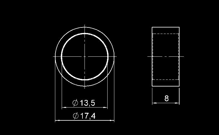
342 Accessories Sensors for Distance and Position ZBL Mr17 Position magnet for HLT 1000 and HLT 2100 Part No.: Magnets for HLT 1000, HLT 2000, HNT 1000 ZBL Mr22 Position magnet for HLT 1000 and HLT 2100 Part No.: ZBL Mr33 Position magnet for HLT 1000 and HLT 2100 Part No.: E /


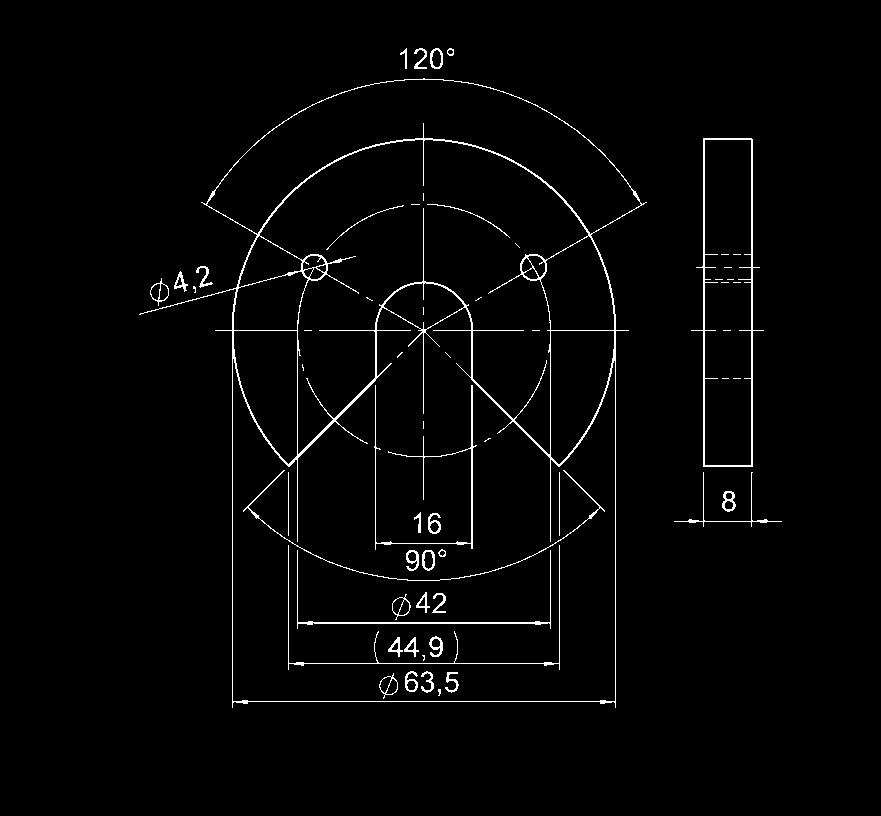
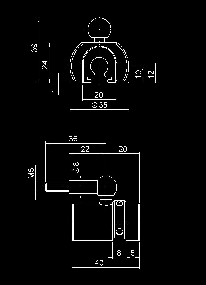


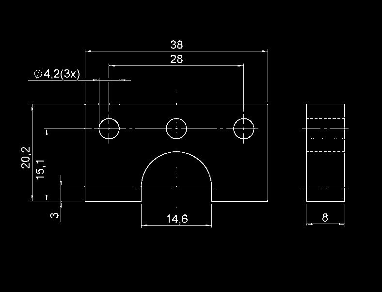
343 ZBL MV63 Position magnet for HLT 1000, HLT 2100 and HLT 2500-L2 Part No.: ZBL MS35-39 Measuring slide for HLT 2500-L2 Part No.: ZBL MU38-20 Position magnet for HLT 1000, HLT 2100 and HLT 2500-L2 Part No.: E /


344 ZBL MF38-18 Position magnet for HLT 2500-F1 Part No.: ZBL MF55-20 Position magnet for HLT 2500-F1 Part No.: ZBL Mounting set Mounting set for HLT 2500 Part No.: Electrical accessories HLT 2000 Electrical connection Signal output HYDAC description Part number M06 Analogue Cable connector C091, 6 pole, straight M08 Analogue Cable connector C091, 8 pole, straight C61 CAN / ZBE 08 cable connector M12x1, 5 pole, DVN right-angle S01 SSI Cable connector M23, 12 pole, straight S01 SSI Cable connector M23, 12 pole, rightangle E /


 Male M12x1 to Binder series 714 M18")

345 Accessories for Service Instruments Aluminium case for HMG 30X0 and accessories Part No.: Bag with carrying strap for HMG 30X0 Part No.: Power supply unit for HMG 30X0, Spare Part Part No.: ZBE 31 Car charger for HMG 30X0 Part No.: ZBE 34 Adapter for HMG 30X0 for connecting HYDAC transmitters ( ma, 2 conductor) Male M12x1 to Binder series 714 M18 (electrical connection type "4") Part No.: ZBE 35 Adapter for HMG 30X0 for connecting HYDAC transmitters ( ma, 2 conductor) Male M12x1 to Male EN (DIN 43650) (electrical connection type "5") Part No.: E /
 for HMG 30X0 to double the number of input sockets Part No.")


346 ZBE 36 Adapter for HMG 30X0 for connecting an AquaSensor AS 1000 Part No.: ZBE 38 Y adapter (black) for HMG 30X0 to double the number of input sockets Part No.: ZBE 41 Y adapter (yellow) for HMG 30X0 for connecting a ContaminationSensor CS 1000 Part No.: ZBE 3010 CAN adapter for HMG 3010 for connecting a CAN-Bus Part No.: Connection cable for HMG 30X0 - PC (USB), Spare Part Part No.: Hydraulic adapter kit for HMG 2 pieces each - Adapter hose DN / 1620 (400 mm and 1000 mm) - Pressure gauge conn / G1/4 - Adapter 1650 / Bulkhead union 1620 / 1620 Part No.: E /11.13 HDS 1000 RPM probe for HMG 30X0 including reflective foil set Part No.: HDS 1000 reflective foil set Spare Part, Quantity: 25 Part No.:
, Spare Part Part No.")
204-51-73 Екатеринбург (343)384-55-89 Иваново (4932)77-34-06 Ижевск (3412)26-03-58 Казань (843)206-01-48 Калининград (4012)72-03-81 Калуга (4842)92-23-67 Кемерово (3842)65-04-62 Киров")
347 UVM 30X0 Module for HMG 30X0 for connecting different input signals Part No.: Plastic case for HMG 500/510 and accessories Part No.: Power supply (230 V AC) for HMG 500/510 Part No.: Connection cable for HMG PC (USB), Spare Part Part No.: Архангельск (8182) Астана +7(7172) Белгород (4722) Брянск (4832) Владивосток (423) Волгоград (844) Вологда (8172) Воронеж (473) Екатеринбург (343) Иваново (4932) Ижевск (3412) Казань (843) Калининград (4012) Калуга (4842) Кемерово (3842) Киров (8332) Краснодар (861) Красноярск (391) Курск (4712) Липецк (4742) Магнитогорск (3519) Москва (495) Мурманск (8152) Набережные Челны (8552) Нижний Новгород (831) Новокузнецк (3843) Новосибирск (383) Орел (4862) Оренбург (3532) Пенза (8412) Пермь (342) Ростов-на-Дону (863) Рязань (4912) Самара (846) Санкт-Петербург (812) Саратов (845) Смоленск (4812) Сочи (862) Ставрополь (8652) Тверь (4822) Томск (3822) Тула (4872) Тюмень (3452) Ульяновск (8422) Уфа (347) Челябинск (351) Череповец (8202) Ярославль (4852) Единый адрес для всех регионов: hcd@nt-rt.ru
Electronics Transmitters, Switches, Diagnostics
 www.comoso.com Electronics Transmitters, Switches, Diagnostics www.comoso.com About HYDAC HYDAC stands for worldwide presence and accessibility to the customer. HYDAC has over 1000 distributors worldwide
Portable Data Recorder HMG 500
 13 Portable Data Recorder HMG 500 14 Description: Special features: Portable 2-channel data recorder Simple and user-friendly key operation Large LCD display including battery status indication 2 sensor
Stand: ELECTRONIC Product News 2010
 Stand: 13.10.2010 ELECTRONIC Product News 2010 Content Page Linear Position Sensors - HLT 1000 for mobile applications 5 - HLT 2000 for industrial applications 7 Electronic Position Switch - HLS 100 9
OEM Products for Large Volume Production:
 OEM Products OEM Products for Large Volume Production Areas of application for our OEM products for large volume production range from mobile and stationary industrial hydraulics, to pneumatics, machine
FESTO. Документация. Датчики положения SRBS. По вопросам продаж и поддержки обращайтесь:
 FESTO Документация Датчики положения SRBS По вопросам продаж и поддержки обращайтесь: Архангельск (8182)63-90-72 Астана +7(7172)727-132 Белгород (4722)40-23-64 Брянск (4832)59-03-52 Владивосток (423)249-28-31
Electronic Pressure Switch EDS 300
 Electronic Pressure Switch EDS 300 Description: The EDS 300 is a compact, electronic pressure switch with integral digital display. Four different output models are available: with one switching point,
Electronic Level Switch ENS 3000
 Electronic Level Switch ENS 3000 Description: The ENS 3000 is an electronic level switch with integrated display. The instrument has 1, 2 or 4 switching outputs and an analogue output signal is available
Описание на блоки питания. Модель 3500/10E
 По вопросам продаж и поддержки обращайтесь: btn@nt-rt.ru www.bently.nt-rt.ru Архангельск (8182)63-90-72, Астана+7(7172)727-132, Белгород(4722)40-23-64, Брянск(4832)59-03-52, Владивосток(423)249-28-31,
Electromotoric actuators
 ACVATIX Electromotoric actuators for Combi-valve types VPI5.., D5 3 SSD3.. SSD8.. SSD6.. SSD3.. operating voltage AC 30 V 3-position control signal SSD8.. operating voltage AC V 3-position control signal
Linear Position Transducer HLT 1000-R2
 7 Linear Position Transducer HLT 1000-R2 Description: The sensor works on the principle of magnetostriction. This measuring principle determines with high accuracy the position, distance and/or speed and
Distance and Position Sensors
 Distance and Position Sensors SENSORS FOR DISTANCE AND POSITION Using various measuring techniques, HYDAC offers different distance and position sensors for a wide array of mobile and stationary applications.
Linear Position Transducer HLT 1000-R2
 Linear Position Transducer HLT 1000-R2 Description: The sensor works on the principle of magnetostriction. This measuring principle determines with high accuracy the position, distance and/or speed and
Контроллеры автономные серии Trajexia MC02 ТЕХНИЧЕСКИЕ ХАРАКТЕРИСТИКИ
 Контроллеры автономные серии Trajexia MC02 ТЕХНИЧЕСКИЕ ХАРАКТЕРИСТИКИ По вопросам продаж и поддержки обращайтесь: Архангельск (8182)63-90-72 Астана +7(7172)727-132 Белгород (4722)40-23-64 Брянск (4832)59-03-52
MANUAL SC-System. Signal Conditioner. По вопросам продаж и поддержки обращайтесь: Единый адрес:
 PROCESS AUTOMATION MANUAL SC-System Signal Conditioner По вопросам продаж и поддержки обращайтесь: Архангельск ()-90- Астана +()- Белгород ()0-- Брянск ()9-0- Владивосток ()9-- Волгоград ()-0- Вологда
Описание на ударные молотоки. Модели , ,
 По вопросам продаж и поддержки обращайтесь: btn@nt-rt.ru www.bently.nt-rt.ru Архангельск (8182)63-90-72, Астана+7(7172)727-132, Белгород(4722)40-23-64, Брянск(4832)59-03-52, Владивосток(423)249-28-31,
Описание на пьезодатчики скорости. Модель
 По вопросам продаж и поддержки обращайтесь: btn@nt-rt.ru www.bently.nt-rt.ru Архангельск (8182)63-90-72, Астана+7(7172)727-132, Белгород(4722)40-23-64, Брянск(4832)59-03-52, Владивосток(423)249-28-31,
Описание на беспроводные системы отслеживания. Серия wsim
 По вопросам продаж и поддержки обращайтесь: btn@nt-rt.ru www.bently.nt-rt.ru Архангельск (8182)63-90-72, Астана+7(7172)727-132, Белгород(4722)40-23-64, Брянск(4832)59-03-52, Владивосток(423)249-28-31,
Temperature Switches
 ETS 00 Series Temperature Switch for Inline and Tank Mounting Applications Description The ETS 00 is a compact electronic temperature switch with 4-digit digital display. Pressure resistant to 8700 psi,
Condition Monitoring Unit CMU 1000
 Condition Monitoring Unit CMU 1000 15 Description: The CMU1000 is an electronic evaluation unit designed for permanent online condition monitoring of machines and systems. In order to achieve this, the
Описание на сейсмозонды. Модели 9200, 74712
 По вопросам продаж и поддержки обращайтесь: btn@nt-rt.ru www.bently.nt-rt.ru Архангельск (8182)63-90-72, Астана+7(7172)727-132, Белгород(4722)40-23-64, Брянск(4832)59-03-52, Владивосток(423)249-28-31,
JUMO TYA 202
 Тиристорный модуль JUMO TYA 202 www.jumo.nt-rt.ru По вопросам продаж и поддержки обращайтесь: Архангельск (8182)63-90-72 Астана +7(7172)727-132 Белгород (4722)40-23-64 Брянск (4832)59-03-52 Владивосток
Azbil. Технические характеристики
 Azbil Технические характеристики Фотоэлектрические датчики HP 100, НР200, НР300 По вопросам продаж и поддержки обращайтесь: Архангельск (8182)63-90-72 Астана +7(7172)727-132 Белгород (4722)40-23-64 Брянск
Electronics. Safe, Accurate, Reliable
 Electronics Safe, Accurate, Reliable About HYDAC HYDAC stands for worldwide presence and accessibility to the customer. HYDAC has over 000 distributors worldwide and more than 0 wholly owned branches.
Electromotoric actuators
 SSA.. without auxiliary switch ACVATIX Electromotoric actuators SSA.. with auxiliary switch For radiator valves, MiniCombiValves (MCV) and small valves SSA3.. SSA8.. SSA6.. SSA3.. operating voltage AC
Описание на высокотемпературные системы близости. Модель 3300
 По вопросам продаж и поддержки обращайтесь: btn@nt-rt.ru www.bently.nt-rt.ru Архангельск (8182)63-90-72, Астана+7(7172)727-132, Белгород(4722)40-23-64, Брянск(4832)59-03-52, Владивосток(423)249-28-31,
Описание на системы наблюдения состояния ветрогенераторов. Модель 60M100
 По вопросам продаж и поддержки обращайтесь: btn@nt-rt.ru www.bently.nt-rt.ru Архангельск (8182)63-90-72, Астана+7(7172)727-132, Белгород(4722)40-23-64, Брянск(4832)59-03-52, Владивосток(423)249-28-31,
Modular pressure transmitters for harsh environments DST P500, DST P507 and DST P550
 Data sheet Modular pressure transmitters for harsh environments DST P500, DST P507 and DST P550 The P500 / P507 / P550 utilizes the thin film strain gauge sensing technology, incorporating an hermetically
ЭЛЕКТРУМ АВ. Паспорт (eng)
") ЭЛЕКТРУМ АВ Паспорт (eng) Реле постоянного тока С трансформаторной изоляцией По вопросам продаж и поддержки обращайтесь: Архангельск (882)63-90-72 Астана +7(772)727-32 Белгород (722)0-23-6 Брянск (832)59-03-52
ЭЛЕКТРУМ АВ Паспорт (eng) Реле постоянного тока С трансформаторной изоляцией По вопросам продаж и поддержки обращайтесь: Архангельск (882)63-90-72 Астана +7(772)727-32 Белгород (722)0-23-6 Брянск (832)59-03-52
Wi-Fi точки серии EKI-6311GN, 6331AN ТЕХНИЧЕСКИЕ ХАРАКТЕРИСТИКИ
 Wi-Fi точки серии EKI-6311GN, 6331AN ТЕХНИЧЕСКИЕ ХАРАКТЕРИСТИКИ По вопросам продаж и поддержки обращайтесь: Архангельск (8182)63-90-72 Астана +7(7172)727-132 Белгород (4722)40-23-64 Брянск (4832)59-03-52
LOGOSCREEN fd
 Экранный регистратор LOGOSCREEN fd www.jumo.nt-rt.ru По вопросам продаж и поддержки обращайтесь: Архангельск (8182)63-90-72 Астана +7(7172)727-132 Белгород (4722)40-23-64 Брянск (4832)59-03-52 Владивосток
Electronic pressure switch with display Model PSD-4
 Electronic pressure measurement Electronic pressure switch with display Model PSD-4 WIKA data sheet PE 81.86 Applications Machine tools Hydraulics and pneumatics Pumps and compressors Special-purpose machine
JUMO MIDAS C08. OEM Pressure Transmitter Basic. Applications. Brief description. Special features. Customer benefits
 Data Sheet 4000 Page /0 JUMO MIDAS C08 OEM Pressure Transmitter Basic Applications compressors machinery and plant engineering industrial pneumatics commercial vehicles building technology Brief description
JUMO MIDAS C08. OEM Pressure Transmitter Basic. Applications. Brief description. Special features. Customer benefits
 sales@jumo.co.uk info.us@jumo.net Page /0 JUMO MIDAS C08 OEM Pressure Transmitter Basic Applications compressors machinery and plant engineering industrial pneumatics commercial vehicles building technology
Miniaturised pressure sensor Model M-10, standard version Model M-11, version with flush diaphragm
 Electronic pressure measurement Miniaturised pressure sensor Model M-10, standard version Model M-11, version with flush diaphragm WIKA data sheet PE 81.25 for further approvals see page 5 MicroTronic
Industrial Pressure Transmitter
 NAT 8 Industrial Pressure Transmitter Swiss based Trafag is a leading international supplier of high quality sensors and monitoring instruments for measurement of and temperature. The industrial transmitter
Electronic pressure switch with display Model PSD-30, standard version Model PSD-31, with flush diaphragm
 Pressure Electronic pressure switch with display Model PSD-30, standard version Model PSD-31, with flush diaphragm WIKA data sheet PE 81.67 Applications Machine tools Hydraulics and pneumatics Pumps and
Pressure transmitter for mobile hydraulic applications With output signals CANopen and J1939
 Electronic pressure measurement Pressure transmitter for mobile hydraulic applications With output signals CNopen and J1939 Model MHC-1 WIK data sheet PE 81.49 pplications Construction machinery gricultural
ACCESSORIES. Accessories for distance and position sensors Magnets for HLT 1000, HLT 2000, HNT Electrical accessories HLT
 Accessories ACCESSORIES Accessories to suit every sensor! Whether it's electrical connectors, mechanical adapters or the instrument mounting clamps, the wide range of products from HYDAC offers solutions
CMP Applications. Features
 CANopen Miniature Pressure Transmitter Swiss based Trafag is a leading international supplier of high quality sensors and monitoring instruments for measurement of pressure and temperature. The CANopen
Коммуникационные платы с шиной серии PCI Express ТЕХНИЧЕСКИЕ ХАРАКТЕРИСТИКИ
 Коммуникационные платы с шиной серии PCI Express ТЕХНИЧЕСКИЕ ХАРАКТЕРИСТИКИ По вопросам продаж и поддержки обращайтесь: Архангельск (8182)63-90-72 Астана +7(7172)727-132 Белгород (4722)40-23-64 Брянск
Описание на бесконтактные датчики близости. Модель 3300 XL 8mm
 По вопросам продаж и поддержки обращайтесь: btn@nt-rt.ru www.bently.nt-rt.ru Архангельск (8182)63-9-72, Астана+7(7172)727-132, Белгород(4722)43-64, Брянск(4832)59-3-52, Владивосток(423)2498-31, Волгоград(844)278-38,
Rotary Measuring Technology Absolute encoders, Multiturn, DeviceNet
 High IP High shaft load capacity Shock/vibration resistant Short-circuit proof Reverse polarity protection Compact and Rugged: Minimal installation depth High shock and vibration values Very compact (only
DMP 333 DMP 333. Industrial Pressure Transmitter For High Pressure. Stainless Steel Sensor. Pressure Transmitter. Industrial
 DMP Industrial Pressure Transmitter For High Pressure Stainless Steel Sensor accuracy according to IEC 60770: standard: 0.5 % FSO option: 0.5 / 0. % FSO Industrial Pressure Transmitter DMP Nominal pressure
Описание на сборные бесконтактные датчики близости. Модель 3300 XL PROXPAC
 По вопросам продаж и поддержки обращайтесь: btn@nt-rt.ru www.bently.nt-rt.ru Архангельск (8182)63-90-72, Астана+7(7172)727-132, Белгород(4722)40-23-64, Брянск(4832)59-03-52, Владивосток(423)249-28-31,
N0524/N1024, N POS/N POS
 N0/N0, N00-POS/N00-POS NON-SPRING RETURN DIRECT-COUPLED DAMPER ACTUATORS FOR FLOATING AND -POSITION CONTROL PRODUCT DATA SPECIFICATIONS Supply voltage N0/N0 Vac/dc -%/+0%, 0/60 Hz N00-POS/N00-POS 0 Vac
Electronic pressure switch with display For sanitary applications Model PSA-31
 Electronic pressure measurement Electronic pressure switch with display For sanitary applications Model PSA-31 WIKA data sheet PE 81.85 Applications Food and beverage industry Pharmaceutical industry Filling
Electronic Temperature Switches. Catalogue. Electronic Temperature Switches. Control. Overview. every move
 Electronic Temperature Switches Catalogue Electronic Temperature Switches Overview Control every move Content Content Overview 3 Electronic Temperature Transducer 3 UTA2 3 Electronic Temperature Sensors
Electronic pressure switch with display For sanitary applications Model PSA-31
 Electronic pressure measurement Electronic pressure switch with display For sanitary applications Model PSA-31 WIKA data sheet PE 81.85 Applications Food and beverage industry Pharmaceutical industry Filling
Installation Instructions Temperature transmitter TAA /00 06/2011
 Installation Instructions Temperature transmitter TAA431 706042/00 06/2011 Contents 1 Functions and features...3 2 Installation...4 2.1 Addressing...4 2.2 Mechanical installation...4 2.3 Connection to
PRESSURE TRANSMITTER
 KS PRESSURE TRANSMITTER GEFRAN SAFETY GUARANTEE Main Features Ranges: from 1 to 1000 bar Nominal Output Signal: 4...20mA (2 wires) 0...10Vdc / 0.1...5.1Vdc / 0.1...10.1Vdc / 0...5Vdc / 1...5Vdc / 1...6Vdc
P30-2. Overview. Pressure Transmitter Datasheet. *High Quality* 3 Years Warranty. At a Glance. Function. Application
 P30-2 Pressure Transmitter Datasheet At a Glance *High Quality* 3 Years Warranty Premium Pressure Transmitter for gauge and pressure measurement with 3 years warranty High repeatability and long-term stability
Pressure transmitter for highest pressure applications Up to 217,500 psi (15,000 bar) Model HP-2
 Model HP-2") Electronic pressure measurement Pressure transmitter for highest pressure applications Up to 217,500 psi (15,000 bar) Model HP-2 WIKA data sheet PE 81.53 Applications Test bench construction Water jet
Electronic pressure measurement Pressure transmitter for highest pressure applications Up to 217,500 psi (15,000 bar) Model HP-2 WIKA data sheet PE 81.53 Applications Test bench construction Water jet
Display and Monitoing Units
 Display and Monitoing Units DISPLAY AND MONITOrING UNITS 13 The universal display unit HDA 5500 provides the means of visualizing and further processing the signals from our sensors. The unit is designed
DCT 531. Industrial Pressure Transmitter with RS485 Modbus RTU. Stainless Steel Sensor
 DCT 5 Industrial Pressure Transmitter with RS85 Modbus RTU Stainless Steel Sensor accuracy according to IEC 60770: : 0.5 % FSO option: 0.5 % FSO Nominal pressure from 0... 00 mbar up to 0... 00 bar output
DS 201P. Electronic Pressure Switch. Pressure Port With Flush Welded Stainless Steel Diaphragm. accuracy according to IEC 60770: 0.
 Pressure Port With Flush Welded Stainless Steel Diaphragm accuracy according to IEC 600: 0. % FSO Nominal pressure from 0... 60 bar up to 00 bar Contacts, or independent PNP contacts, freely configurable
LMP 308. Separable Stainless Steel Probe. Stainless Steel Sensor. accuracy according to IEC 60770: standard: 0.35 % FSO option: 0.25 % FSO / 0.
 LMP 08 Separable Stainless Steel Sensor accuracy according to IEC 60770: standard: 0.5 % FSO option: 0.25 % FSO / 0. % FSO Nominal pressure from 0... mh 2 O up to 0... 250 mh 2 O Output signals 2-wire:
CMP Applications. Features
 CANopen Miniature Pressure Transmitter Swiss based Trafag is a leading international supplier of high quality sensors and monitoring instruments for measurement of pressure and temperature. The CANopen
Absolute Encoders Multiturn
 The multiturn encoders 6 and 8, with interface and combined optical and magnetic sensor technology, offer a maximum resolution of 5 bits. These encoders are programmable via the Ezturn software. The hollow
По вопросам продаж и поддержки обращайтесь:
 По вопросам продаж и поддержки обращайтесь: Архангельск (8182)63 90 72 Астана (7172)727 132 Белгород (4722)40 23 64 Брянск (4832)59 03 52 Владивосток (423)249 28 31 Волгоград (844)278 03 48 Вологда (8172)26
Control IT Booster Pump Controller
 Data Sheet SS/_4 Control IT Booster Pump Controller Protection for the pasteurization process ensuring a high quality, safe product for your customers High visibility LED displays continuous indication
Temposonics. R-Series Profibus. Absolute, Non-Contact Position Sensors. Temposonics RP and RH Stroke length mm
 Temposonics Absolute, Non-Contact Position Sensors R-Series Temposonics RP and RH Stroke length 25 7600 mm Advanced Communication offers Multi-Position Measurement Rugged industrial sensor Linear and absolute
Flow measurement FlexFlow PF20S Flow sensor for industrial applications
 Product highlights Parallel measurement of flow and temperature Flow measurement independent of the mounting position Large measuring range up to 400 cm/s Measurement at high media temperatures up to 125
TSE. Functional Description. Order Code TSE HA /2010. Electrical Pressure Switch N D. p max up to 400 bar (5801 PSI)
") Electrical Pressure Switch TSE HA 90 /010 p max up to 400 bar (5801 PSI) Electronic pressure switch TSE To monitor the pressure in the circuit and the signalisation switching after reaching pre-set pressure
Electrical Pressure Switch TSE HA 90 /010 p max up to 400 bar (5801 PSI) Electronic pressure switch TSE To monitor the pressure in the circuit and the signalisation switching after reaching pre-set pressure
FOUNDATION Fieldbus H1
 По вопросам продаж и поддержки обращайтесь: Архангельск (8182)63-90-72 Астана +7(7172)727-132 Белгород (4722)40-23-64 Брянск (4832)59-03-52 Владивосток (423)249-28-31 Волгоград (844)278-03-48 Вологда (8172)26-41-59
Inclination sensors 1-dimensional, measuring range
 Features Size 52 mm MEMS capacitive measuring principle EN13849 compliant firmware E1 compliant design Interface CANopen, SAE J1939, Analog Connection M12 and cable Protection up to IP 69K Optional GIM500R
NOVOHALL Rotary Sensor non-contacting. Series RSX-7900
 NOVOHALL Rotary Sensor non-contacting Series RSX-7900 Special features very robust design to extreme environmental conditions high shaft load 300 N non-contacting, magnetic measuring angles up to 360 in
Pressure transmitters OsiSense XMLP for industrial applications. Catalogue
 Pressure transmitters OsiSense XMLP for industrial applications Catalogue A compact and optimised product for industrial applications The new OsiSense XMLP pressure transmitters are for regulating fluid
Electronic pressure switch with display For sanitary applications Model PSA-31
 Electronic pressure measurement Electronic pressure switch with display For sanitary applications Model PSA-31 WIKA data sheet PE 81.85 for further approvals see page 8 Applications Food and beverage industry
Absolute encoders - bus interfaces Solid shaft with clamping or synchro flange Magnetic single- or multiturn encoders 14 bit ST / 18 bit MT
 Features Encoder single- or multiturn / CANopen Precise magnetic sensing Angular accuracy up to ±0.15 Additional incremental signals High protection up to IP 67 High resistance to shock and vibrations
Inclination sensors 2-dimensional, measuring range up to ±90
 Features Size 52 mm MEMS capacitive measuring principle EN13849 compliant firmware E1 compliant design Interface CANopen, SAE J1939, Analog Connection M12 and cable Protection up to IP 69K Optional GIM500R
Thread length (overall length) material
 material") Cylindrical Proximity Sensor for Mobile Usage Designed and tested to keep your machines moving IP69k tested and certified for highest water resistance e1 type approval (according to automotive directive
Cylindrical Proximity Sensor for Mobile Usage Designed and tested to keep your machines moving IP69k tested and certified for highest water resistance e1 type approval (according to automotive directive
Встраиваемые промышленные компьютеры автоматизации серии UNO-4000 ТЕХНИЧЕСКИЕ ХАРАКТЕРИСТИКИ
 Встраиваемые промышленные компьютеры автоматизации серии UNO-4000 ТЕХНИЧЕСКИЕ ХАРАКТЕРИСТИКИ П о в о п р о сам п р о д а ж и п о д д е р ж ки обращ айтесь: Архангельск (8182)63-90-72 Астана +7(7172)727-132
M7100 Pressure Transducer
 Pressure Transducer Performance standard to on and off highway engines and vehicle OEMs Rugged for heavy equipment and outdoor use Designed specifically for high volume applications Stainless Steel wetted
Одноплатные промышленные компьютеры половинного размера с шиной PCI/PCIe серии PCI-7000 ТЕХНИЧЕСКИЕ ХАРАКТЕРИСТИКИ
 Одноплатные промышленные компьютеры половинного размера с шиной PCI/PCIe серии PCI-7000 ТЕХНИЧЕСКИЕ ХАРАКТЕРИСТИКИ По вопросам продаж и поддержки обращайтесь: Архангельск (8182)63-90-72 Астана +7(7172)727-132
M5100 Heavy Industrial Pressure Transducer
 CE Compliance Wide Temperature Range Compact Variety of Pressure Ports and Electrical Configurations DESCRIPTION The M5100 series pressure transducers from the Microfused line of MEAS, set a new price
MELT PRESSURE TRANSMITTERS IE SERIES WITH CURRENT OUTPUT AND PLc VERSION
 MELT PRESSURE TRANSMITTERS IE SERIES WITH CURRENT OUTPUT AND PLc VERSION 4-20mA Output The IMPACT series of Gefran, are pressure transmitters, without transmission fluid, for using in High temperature
Pressure sensor For highest pressure applications to 15,000 bar Model HP-2
 Pressure Pressure sensor For highest pressure applications to 15,000 bar Model HP-2 WIKA data sheet PE 81.53 for further approvals see page 6 Applications Test bench construction Water jet cutting High-pressure
Одноплатные компьютеры с архитектурой RISC серии UBC ТЕХНИЧЕСКИЕ ХАРАКТЕРИСТИКИ
 Одноплатные компьютеры с архитектурой RISC серии UBC ТЕХНИЧЕСКИЕ ХАРАКТЕРИСТИКИ По вопросам продаж и поддержки обращайтесь: Архангельск (8182)63-90-72 Астана +7(7172)727-132 Белгород (4722)40-23-64 Брянск
Pressure switch Type KP
 MAKING MODERN LIVING POSSIBLE Data sheet Pressure switch Type KP KP switchs are for use in refrigeration and air conditioning systems to give protection against excessively low suction or excessively high
KINAX WT720 absolute, programmable angular postion transmitter
 For industrial applications in rough environments KINAX WT720 is a robust, absolute angular position transmitter, which is particularly suited to applications in rough environments due to its unique capacitive
Electronic pressure sensors
 Presentation, type XML P For control circuits Presentation Pressure transmitters XML P are characterised by their thin fi lm technology. The stainless steel pressure sensing capsule is directly welded
Absolute encoders - bus interfaces Solid shaft with synchro flange Magnetic single- or multiturn encoders 14 bit ST / 18 bit MT
 EAM60 - solid shaft CANopen - MAGRES Features Encoder single- or multiturn / CANopen Precise magnetic sensing Angular accuracy up to ±0.1 Additional incremental signals High protection up to IP 67 High
Pressure Switch CE40. Digital settings available via IR data communication without actually applying pressure to the unit
 Pressure Switch CE0 NEW IR Communication type Pressure Switch Rev. Fluids/Gasses Utilizing Stainless Diaphragm Utilizes stainless steel diaphragm for use with a wide variety of pressure media Excellent
LS 6600 Technical Datasheet
 Technical Datasheet Switch for level detection and dry-run protection Optimised sensor geometry, easy to clean Measures products with dielectric constant > 1.5 Small and compact KROHNE 06/2011-4001367301
Pneumatic Control/Feedback
 897 /Feedback Type 897 can be combined with... Compact design Integrated pilot valve with manual override Internal control air routing Automatic end position adjustment With ATEX II cat. G/D and cat. D/G
Станции ввода-вывода серии ADAM-5000/485, ADAM-5000/TCP, ADAM-5000E, ADAM-5000L/TCP ТЕХНИЧЕСКИЕ ХАРАКТЕРИСТИКИ
 Станции ввода-вывода серии ADAM-5000/485, ADAM-5000/TCP, ADAM-5000E, ADAM-5000L/TCP ТЕХНИЧЕСКИЕ ХАРАКТЕРИСТИКИ По вопросам продаж и поддержки обращайтесь: Архангельск (8182)63-90-72 Астана +7(7172)727-132
Temposonics. R-Series Profibus. Absolute, Non-Contact Position Sensors. Temposonics RP and RH Measuring length mm
 R-Series Temposonics Absolute, Non-Contact Position Sensors R-Series Temposonics RP and RH Measuring length 5-7600 mm Advanced Communication... offers Multi-Position Measurement Rugged Industrial Sensor
Fusion of electronic pressure sensor and analogue display.
 Fusion of electronic pressure sensor and analogue display. Pressure sensors www.ifm.com/gb/pg fluid sensors and diagnostic systems position sensors and object recognition bus, identification and control
Encoder WDGA 58B CANopen
 Encoder WDGA 58B CANopen www.wachendorff-automation.com/wdga58bcan Wachendorff Automation... systems and encoders Complete systems Industrial rugged encoders to suit your application Standard range and
Operating Instruction for Turbine-wheel Flow Meter. Model: DRS
 Operating Instruction for Turbine-wheel Flow Meter Model: DRS . Contents. Contents... 2 2. Note... 3 3. Instrument Inspection... 3 4. Regulation Use... 3 5. Operating Principle... 4 6. Mechanical Connection...
U7100 Pressure Transducer
 Performance standard for on and off highway engine & vehicle OEMs Rugged for heavy equipment and outdoor use such as HVAC refrigeration systems Designed specifically for high volume applications Stainless
FlexBar HRT Pressure Transmitter
 FlexBar HRT Pressure Transmitter 4...0 ma, -wire transmitter, HART communication Some hygienic connections conform to -A standards, FDA demands and EHEDG guidelines Configurable span, unit and damping
HMI COMPONENTS & SOLUTIONS
 THE BROADEST RANGE OF HMI COMPONENTS & SOLUTIONS По вопросам продаж и поддержки обращайтесь: Архангельск (8182)63-90-72 Астана (7172)727-132 Астрахань (8512)99-46-04 Барнаул (3852)73-04-60 Белгород (4722)40-23-64
PHOENIX CONTACT - 08/2009. Features. DANGER OF EXPLOSION! Only remove equipment when it is disconnected and not in the potentially explosive area.
 Primary-switched power supply for building automation INTERFACE Data sheet 103505_en_02 1 Description PHOENIX CONTACT - 08/2009 Features STEP POWER power supply units for building automation The new STEP
FLEX Ex Spring Clamp Terminal Base
 Installation Instructions FLEX Ex Spring Clamp Terminal Base (Cat. No. 1797-TB3S) 1 10 11 4 Only remove this cover plug if connecting another terminal base unit. 3 5 6 12 2 7 8 9 41253 Component Identification
Operating Instructions for Low Volume Rotating Vane Flow Meter. Model: DPL-1P... DPL-1V... DPL-1E...
 Operating Instructions for Low Volume Rotating Vane Flow Meter Model: DPL-1P... DPL-1V... DPL-1E... 1. Contents 1. Contents... 2 2. Note... 3 3. Instrument Inspection... 3 4. Regulation Use... 3 5. Operating
HIGH ACCURACY PRESSURE TRANSDUCERS
 HIGH ACCURACY PRESSURE TRANSDUCERS PX409-100GV, RUGGEDIZED DESIGN For Aerospace, Automotive, Test and Industrial Applications U 0.08% BSL Includes Linearity Hysteresis and Repeatablity U Broad Temperature
Pneumatic Control/Feedback
 897 /Feedback Type 897 can be combined with... Compact design Integrated pilot valve with manual override Internal control air routing Bright LED position indicator Automatic end position adjustment Type
THERMASGARD TM 65. Immersion screw-in duct temperature measuring transducer, calibratable, with multi-range switching and active output TECHNICAL DATA
 Patented quality product (Immersion sensor patent no. DE 10 2012 017 500.0) Calibratable temperature measuring transducer THERMASGARD with eight switchable measuring ranges, continuous linear output, enclosure
Easy Flow Indicator Magnetisch-Induktiver Durchflussmesser. Type 8024 For Insertion Fittings. Analog Flow Rate Indicator, 1/2"-16"; P=87 PSI
 Analog Flow Rate Indicator, 1/2"-16"; P=87 PSI Advantages / Benefits Reduced costs of ownership up to 6% Economic integration in pipe systems without any additional piping Shows flow rate with a clear,