The J-Series d&b J-Series J-SUB D12 J12 J-Series
|
|
|
- Rodney Barker
- 5 years ago
- Views:
Transcription

1 The J-Series
2 The J-Series The d&b J-Series continues the established d&b audiotechnik approach to the design and manufacture of loudspeaker systems. It is intended for use in large-scale sound reinforcement applications, providing incredibly quick and easily configurable array solutions even in the most arduous situations. Control of dispersion behaviour is a particular fixation at d&b, as is keeping the size and weight of systems to an absolute minimum; these are both areas in which the J-Series excels. It also embodies the d&b holistic approach to sound reinforcement solutions: integrating loudspeakers, electronics, mechanical deployment assemblies, remote control functions, transport solutions and set up design tools for precise calculation of array performance. The J-Series carries on the d&b specific combination of a neutral, intelligible sound character that is clear and transparent even at the highest sound pressure levels providing the engineer with an efficient, effortless tool and a neutral platform. The crystal clear and detailed audio performance with an extraordinarily smooth and even frequency response over distance, high dynamic bandwidth, extreme power and headroom capabilities makes the J-Series the ultimate choice for the far reaching reinforcement of any sound genre. All the components needed to suspend the loudspeakers within the bespoke three point BGV C1 compliant J-Series flying system are integrated into the cabinets ensuring speedy deployment in all the intended applications, whether ground supported or flown. The use of neodymium magnets in the driver assemblies increases the ratio of weight against output power to significantly higher levels. The ArrayCalc calculator predicts the physical and acoustical performance of arrays; enabling simple and accurate system planning and negates trial and error in highly pressured onsite situations. The 3-way J8 and J12 loudspeakers are acoustically matched and constructed to be mechanically compatible sharing the same vertical directivity, size, footprint, weight, rigging and driver complement. The coherent vertical wave front that is produced enables the construction of vertical arrays starting from a minimum of four up to a maximum of twenty-four cabinets with a fully user and venue definable vertical profile. Both loudspeakers use an active crossover between the low and mid and a passive crossover between the mid and high frequencies. J8 and J12 are completely symmetrical horizontally with two 12" neodymium low frequency drivers placed to the outsides in a dipolar arrangement. Their hornloaded coaxial mid and high frequency section is mounted in the centre of the loudspeakers. The mid frequency horn uses a 10 driver, while the high frequency section consists of two 1.4 exit HF compression drivers with 3" voicecoils mounted to a dedicated wave-shaping device. The J8 s 80 horizontal constant directivity dispersion pattern, maintained down to 250 Hz, and its high output capability can cover a distance range of over 100 m (330 ft) depending on the climatic conditions. The J12 has a wider horizontal dispersion pattern of 120 maintained down to 250 Hz, which is particularily useful for short and medium throw applications up to approximately 40 m (130 ft). Using a combination of J8 and J12 cabinets enables the user to create a venue specific dispersion and energy pattern. The J-SUB completes the Series sharing the same width as the other two loudspeakers and is equipped with compatible flying fittings. The bass-reflex design uses three 18 high excursion drivers, one of which radiates to the rear to produce cardioid or hypercardioid subwoofer performance both in flown and ground stacked configurations. It may be flown as a separate column or integrated at the top of a J-Series array. While it can be deployed in a conventional left and right ground stacked set up, it is particularly suited for use in distributed bass-arrays to achieve an even venue specific coverage pattern. All J-Series loudspeakers are finished with a PCP (Polyurea Cabinet Protection) coating that provides resistance for mobile systems to the adverse effects on cabinets in changing ambient outdoor conditions. The d&b D12 amplifier contains the loudspeaker specific controller configurations for all the J-Series loudspeakers and provides the necessary amplification. This amplifier is specially designed and manufactured by d&b utilizing digital signal processing and incorporates configuration set ups for the d&b loudspeaker range including switchable functions for precisely tailoring the system response for a wide variety of applications. A user definable 4-band parametric equalizer and a delay capability is provided in every amplification channel to reduce the need for external processing units and increase the control permutations for the loudspeaker system elements. The D12 amplifier uses a switch mode power supply that automatically selects the mains supply voltage. It also has network remote control and monitoring of the system functions as well as Load monitoring and System check that can monitor loudspeaker driver status. The D12 amplifier has both analog and digital signal inputs as well as link outputs and also incorporates d&b SenseDrive. To complete the picture, the high fidelity of the J-Series pushes all the boundaries of the d&b maxim; to maintain the compatibility and sound character between systems enabling them to be easily combined. Together these components create complete, integrated reinforcement solutions in situations from the simplest to the most complex.


3 The J-Series J8, J12 loudspeaker J subwoofer D12 amplifier
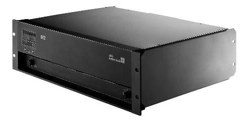
4 ISP GR OVL A MUTE LEVEL PUSH MENU B ISP GR OVL ON OFF POWER The D12 amplifier D12 amplifier The D12 amplifier is a two channel power amplifier developed and manufactured by d&b utilizing Digital Signal Processing (DSP) to incorporate loudspeaker specific configuration information and functions. It is designed for use with d&b loudspeakers, has both digital and analog signal inputs as well as link outputs, remote control and monitoring capabilities and a switch mode power supply. The level control incorporates a digital rotary encoder enabling selection of all operating modes in conjunction with a Liquid Crystal Display (LCD). Loudspeaker specific configuration set ups for all current d&b loudspeakers are contained within the D12 and a linear mode is provided for loudspeakers such as the d&b MAX and MAX12. The digital elements of the D12 are specified and constructed to achieve audio performance meeting or exceeding that of analog devices. The Digital Signal Processing is used to provide the loudspeaker specific configurations, sophisticated protection circuits modelling thermal and mechanical driver behaviour, and the switch functions such as CUT/HFA/HFC/CPL as detailed in each loudspeaker section. User definable equalization and delay functions are incorporated in each channel of the D12 and can be used for applications, such as front fills, or under balcony delays, without the need for external processors. The 4-band parametric equalizer provides optional Boost/Cut or Notch filtering and the signal delay capability allows delay settings of up to 340 msec. (= 100 m/328 ft) to be applied independently to either channel. A signal generator offering pink noise or sine wave program is also incorporated for test and alignment purposes. Each unit can be given a unique Device Name to simplify identification and a password protected LOCK function is also incorporated to inhibit unauthorized set up changes. The D12 amplifier can detect incoming Pilot signals at its input (Input monitoring) and uses the Load monitoring and System check function to ascertain the status of the loudspeaker impedance. d&b System check is designed to verify that the system performs within a predefined condition and can be initiated at the end of a show for example. d&b Load monitoring on the other hand enables an automatic and continuous impedance monitoring and along with Input monitoring is designed for incorporation within applications specified to the requirements stated in the International Standard IEC Sound Systems for Emergency Purposes. Both can determine the status of an LF or HF driver in systems with multiple elements, even if these are crossed over passively. Errors are reported on the front panel display and /or with audible tones. System check errors can be monitored using the remote control and monitoring functions provided via the REMOTE interface. The D12 utilizes an autosensing switch mode power for mains supply voltages 115/230 V, Hz (optional 100/200 V) with overvoltage protection. A temperature and signal controlled fan is used to cool the internal assemblies. The D12 is specifically designed to produce high power into low impedance loads, typically those between 4 and 16 ohms. Due to differences in impedance response against frequency, the maximum number of cabinets driven by each channel varies depending on the loudspeaker type. The D12 provides d&b SenseDrive for use with the LF drivers in d&b active loudspeakers and subwoofers. In the LF region the impedance of a loudspeaker can change significantly with frequency, cone excursion and cable length, leading to considerable linear and non-linear distortion. SenseDrive uses an extra conductor in the loudspeaker cable as feedback that modifies the amplifier output behaviour to compensate for these effects. The result is more accurate control of the diaphragm improving the transient response. The rear panel houses: an I /O panel containing analog signal inputs with link outputs for each channel, and an AES /EBU digital input with a link output; a mains panel that houses loudspeaker outputs that are optionally either EP5, NL4 or NL8. The two RJ 45 REMOTE sockets at the rear integrate the D12 into the d&b Remote network via CAN-Bus allowing it to be remotely controlled and /or monitored. A SUB-D9 SERVICE interface (RS 232) is also provided to enable operating software and loudspeaker updates to be loaded into the unit. When multiple units are integrated into a d&b Remote network, up to 63 amplifiers can be simultaneously updated from a central location using the d&b R10 service software. D12 D12 front view D12 rear view
5 The D12 amplifier Displays ISP A /B...Input Signal Present indicator (green) GR A /B...Gain Reduction indicator (yellow) OVL A /B...Overload /Error indicator (red) MUTE A /B...Mute /Standby indicator (green) Liquid Crystal Display (LCD)...Graphic display/120 x 32 Pixel Controls POWER...Main power switch MUTE A /B...Mute /Standby switch LEVEL /PUSH MENU...Digital rotary encoder...access to all functions (Channel A /B) including: Level control db to +6 db with 0.5 db detents Configurations...Loudspeaker specific configurations and functions...(e.g. CUT/HFA /HFC /CPL) 4-band equalizer...optional PEQ/Notch Delay setting msec. with 0.1 msec. detents System set ups...all current d&b loudspeakers /...linear (MAX /MAX12) Protection...Operator input inhibit /password protection Remote control...rib /CAN-Bus Device name...15 alphanumeric digits Display illumination...off /On /Timeout 10 sec. Frequency generator...pink noise or Sine wave, 10 Hz - 20 khz...with 1 Hz detent, Level: 57.5 db to +6 db with 0.5 db detents Buzzer...Audible signal for error messages Monitoring according to IEC Sound Systems for Emergency Purposes Input monitoring...detecting external Pilot signal Load monitoring...continous impedance monitoring...using Pilot signal at 10 Hz and 20 khz System check...manual impedance measurement...to calibrate before, and verify after use Connectors INPUT ANALOG CH A /CH B...3 pin XLR female* Input impedance...44 kohm, electronically balanced Maximum input level dbu LINK ANALOG CH A /CH B...3 pin XLR male*...parallel to INPUT INPUT DIGITAL AES /EBU...3 pin XLR female* Input impedance ohms, electronically balanced Sampling...48 khz /96 khz /2 Ch/n Synchronisation...Word-Sync: PLL-locked to source (slave mode) LINK DIGITAL output...3 pin XLR male...electronically balanced, analog signal buffering...power fail relay (Bypass) OUT CHANNEL A /B...Optional EP5 /NL4 /NL8 REMOTE...2 x RJ 45 parallel SERVICE...SUB-D9 female Protection circuits Mains inrush current limiter...5 A RMS at 230 V...10 A RMS at 115 /100 V Speaker switch on delay...approx. 2 sec. Overvoltage protection...up to 400 VAC Self-resetting overtemperature protection...75 C /167 F Output short and open circuit protection...±60 A peak Data (linear setting with subsonic filter) Rated output power (THD+N < 0.1%) x 750 W into 8 ohms, both channels are driven...2 x 1200 W into 4 ohms, both channels are driven Frequency response ( 1 db)...28 Hz - 40 khz THD+N (20 Hz - 20 khz)...< 0.1 % IM (SMPTE)...< 0.1 % S/N ratio (unweighted, RMS)...> 110 dbr Damping factor (20 Hz - 1 khz into 4 ohms)...> 200 Crosstalk (20 Hz - 20 khz)...< 65 dbr Digital Signal Processing Sampling rate...96 khz /27 Bit ADC /24 Bit DAC Basic delay analog input msec. ADC/Input /DAC dynamic...> 110 /127/110 db Power supply Autosensing switch mode power supply for /230 V, Hz...optional 100/200 V, Hz Mains connector...powercon PowerCon is a registered trademark of the Neutrik AG, Liechtenstein Dimensions, weight Height x width x depth...3 RU x 19 x 353 mm...3 RU x 19 x 13.9 Weight...13 kg /28.7 lb * XLR pin assignment: 1 = GND, 2 = pos. signal, 3 = neg. signal
6 ISP GR OVL A MUTE B ISP LEVEL MUTE PUSH MENU POWER LEVEL PUSH MENU GR OVL ISP ISP LEVEL MUTE PUSH MENU POWER GR OVL ISP GR GR OVL OVL LEVEL MUTE PUSH MENU POWER A MUTE B LEVEL PUSH MENU ISP GR OVL D12 ISP GR OVL ISP GR OVL A MUTE B LEVEL PUSH MENU ISP GR OVL OFF ON POWER OFF ON POWER OFF ON POWER The d&b Remote network d&b Remote network Remote interfaces are fitted into d&b's amplifiers for control and monitoring of functions and features provided within these units. The architecture of the d&b Remote system allows control of each channel of the amplifier as a single entity and enables the creation Terminating connector D12 D12 PC with terminated CAN-Bus interface running ROPE C of groups of loudspeakers in as little, or as much detail as required E-PAC by the application. E-PAC The features and functions of the E-PAC and D12 amplifiers E-PAC Daisy chain that can be remotely controlled and /or monitored using the d&b Remote network are: d&b Remote network with ROPE C Power on /off and MUTE Loudspeaker configuration Input selection Level control, range 63.5 db in 0.5 db steps Function switches; CUT /HFA /HFC /CPL /etc. User definable delay User definable four band parametric equalizer Z6110 Peak USB to CAN interface (ISO) System check All front panel indicators Gain reduction Device diagnostic The remote interface fitted to d&b's amplifiers is a Controller Area PCAN PO Network (CAN) bus. Each D12 and E-PAC has two REMOTE connectors (RJ 45) to enable the CAN-Bus to be daisy chained through them. CAN-Bus segments are terminated at both ends using RJ 45 M Terminators. A simple d&b Remote network application consists of a computer, a Peak USB to CAN interface (ISO) or Peak PCI to CAN interface Z6111 Peak PCI to CAN interface (ISO) (ISO), a D-SUB 9 F to 2 x RJ 45 F CAN adapter, CAT 5 shielded twisted pair cable with shielded RJ 45 connectors and d&b D12 or E-PAC amplifiers. Up to 504 devices can be incorporated into one application. TI 312 d&b Remote network gives a detailed description of the CAN-Bus, cabling requirements and the interfaces available and can be downloaded from the Documentation section at Z6116 RJ 45 M Terminator Z6117 D-SUB 9 F to 2 x RJ 45 F CAN adapter


7 The ROPE C remote control software The R10 service software ROPE C ROPE C with System check ROPE C remote control software ROPE C (Remote OPerating Environment CAN-Bus) is a graphical drag and drop user interface enabling the construction of a screen based virtual control surface for complete d&b systems, using the d&b Remote network. Operating elements for all d&b D12 and E-PAC loudspeaker specific controller configurations can easily be incorporated into an application from ROPE C's internal library. ROPE C runs on PCs operating Microsoft Windows 2000/XP*. The loudspeaker specific operating elements of ROPE C incorporate gain controls, level displays, indicators for ISP /OVL /GR and switch functions such as CUT/HFA /HFC /CPL. The operating elements use a two level format, the level one view contains the most important information and controls allowing a fast overview of a large system. The second level contains more detailed information and controls. Group functions such as system on /off, master level and mute may be added to the control surface, and setting for Load monitoring and Input monitoring can be defined. ROPE C has extensive facilities for storing and recalling system settings allowing these to be repeated, as and when required. It also enables the remote access of the System check function to verify that the system performs within a predefined condition. The unique device IDs used to identify each amplifier can be edited using the rotary encoder and the LCD display on the front panel of the d&b amplifiers. This makes it easy to transport a ROPE C application to an identical, but completely different set of equipment at another location. For fixed, or installed systems, ROPE C can be configured to offer access to different levels of system control. This can be tailored to the operational requirements with simplified control possibilities for daily use and more complex control for system configuration purposes. Password protection is available to restrict access. R10 service software When multiple amplifiers are integrated into a d&b Remote network the R10 service software enables the firmware update of up to 63 amplifiers simultaneously from a central location. Predefined standard warehouse or installation D12 settings can also be loaded and saved in the R10 to then be re-loaded into other D12s. * Microsoft and Windows 2000/XP are either registered trademarks or trademarks of Micorsoft Corporation in the United States and/or other countries

8 The J8 loudspeaker J8 loudspeaker The J8 loudspeaker is designed specifically for use in large-scale sound reinforcement applications. It is a 3-way design housing 2 x 12" LF drivers, one hornloaded 10" MF driver and two 1.4" exit HF compression drivers with 3" voicecoils mounted to a dedicated waveshaping device. The mechanical and acoustical design enables flown vertical columns of up to twenty-four loudspeakers to be suspended using vertical splay angles between them of 0 to 7 with a 1 resolution. The cylindrical wave segments produced couple coherently in the vertical plane. The symmetrical dipolar arrangement of the neodymium LF drivers around the centrally mounted coaxial MF and HF components allows a smooth overlap of the adjacent frequency bands in the crossover design. This results in an exceptional 80 horizontal constant directivity dispersion control nominally being maintained down to 250 Hz. The J8 is acoustically and mechanically compatible with the J12 loudspeaker. It can be used in columns of purely J8 loudspeakers or combined with J12s and /or with J-SUBs. Cabinets are mechanically connected using the rigging links on both sides of the cabinet front, and with a central rigging link on the rear of the loudspeaker. The J8 cabinet is constructed from marine plywood and has an impact and weather protected PCP (Polyurea Cabinet Protection) finish. The front of the loudspeaker cabinet is protected by a rigid metal grill, the side and rear panels incorporate four handles, and two EP5 or NL8 connectors wired in parallel are also mounted at the rear. J8 horizontal dispersion characteristics** J8 cabinet dimensions in mm (inches) System data Frequency response ( 5 db standard)...48 Hz - 17 khz Frequency response ( 5 db CUT mode)...85 Hz - 17 khz Max. sound pressure (1 m, free field)* db Polarity to controller INPUT (XLR pin 2: +/3: )...LF: +/MHF: + Loudspeaker data Nominal impedance LF/MHF...6/12 ohms Power handling capacity LF (RMS /peak 10 ms) /2000 W Power handling capacity MHF (RMS /peak 10 ms) /800 W Nominal dispersion angle (horizontal)...80 Splay angle settings (1 increment) Components...2 x 12 driver/1 x 10 driver...2 x 1.4 exit compression driver...passive crossover network Connections...2 x EP5 (optional 2 x NL8) Pin assignments... EP5...1: LF+/2: LF /3: MHF+/4: MHF /5: SenseDrive NL8...1+: LF+/1 : LF /4+: MHF+/4 : MHF /3 : SenseDrive Weight...60 kg (132 lb) * Broadband measurement, pink noise, crest factor 4, peak measurement, linear weighting ** Dispersion angle vs frequency plotted using lines of equal sound pressure (isobars) at 6 db and 12 db
9 The D12 configuration J8 frequency response standard and CUT settings (single cabinet) Frequency response correction of HFC circuit Frequency response correction of CPL circuit * For further information please refer to the d&b TI 340 SenseDrive which is available for download at J8 with D12 Selecting 2-way active mode with the J8 configuration enables up to two J8 loudspeakers to be driven actively by the D12 amplifier. J8 loudspeakers are amplified by the two channels of the D12 providing the active crossover between the low and mid /high sections, whilst the mid and high frequency drivers are crossed over passively within the cabinet. The D12 amplifier has two set ups for J8 cabinets, the Line and the Arc configuration, depending on the curvature of the array. The J8 Line configuration is selected when groups of four or more J8 cabinets are coupled to a straight long throw array section, where the splay angles to adjacent cabinets are 0 or 1. Compared with the loudspeakers used in the curved array sections, those used in the straight array sections extend the acoustical near field, and therefore require a different tonal balance. By using the Line configuration, the mid/high range is reduced to compensate for this. The J8 Arc configuration is selected when J8 cabinets are used in curved array sections, where the splay angles to adjacent cabinets are 2 or more. Within a typical J-shaped array both amplifier configurations are used. For acoustic adjustment the functions CUT, HFC and CPL can be selected. Set to CUT, the J8 low frequency level is reduced. The J8 is now configured for use with the d&b J subwoofer. Selecting the HFC (High Frequency Compensation) circuit compensates for loss of high frequency energy due to absorption in air when loudspeakers are used to cover far field listening positions. The HFC circuit has two settings which should be used selectively, HF1 for cabinets covering distances larger than 40 m (130 ft) and HF2 for those covering distances larger than 80 m (260 ft). This can be used to achieve the correct sound balance between close and remote audience areas, whilst all amplifiers driving the array can be fed with the same signal and the whole array performs with comparable headroom. The CPL (Coupling) circuit compensates for coupling effects between the cabinets; these effects increase as the length of the array is extended. CPL begins gradually at 2 khz, with the maximum attenuation below 100 Hz, providing a balanced frequency response when J8 cabinets are used in arrays of five or more. The function of the CPL circuit in the D12 amplifier is shown in the diagram opposite and can be set in db attenuation values between 9 and 0. The D12 incorporates d&b SenseDrive* for accurate control of LF driver membranes in J8 loudspeakers, resulting in an extremely precise bass performance, even at high levels. SenseDrive is only available using a D12 fitted with EP5 or NL8 connectors and appropriate 5-wire cabling.

10 The J12 loudspeaker J12 loudspeaker The J12 loudspeaker is designed specifically for use in large-scale sound reinforcement applications. It is a 3-way design housing 2 x 12" LF drivers, one hornloaded 10" MF driver and two 1.4" exit HF compression drivers with 3" voicecoils mounted to a dedicated waveshaping device. The mechanical and acoustical design enables flown vertical columns of up to twenty-four loudspeakers to be suspended using vertical splay angles between them of 0 to 7 with a 1 resolution. The cylindrical wave segments produced couple coherently in the vertical plane. The symmetrical dipolar arrangement of the neodymium LF drivers around the centrally mounted coaxial MF and HF components allows a smooth overlap of the adjacent frequency bands in the crossover design. This results in an exceptional 120 horizontal constant directivity dispersion control nominally being maintained down to 250 Hz. The J12 is acoustically and mechanically compatible with the J8 loudspeaker. It can be used in columns of purely J12 loudspeakers or combined with J8s and /or with J-SUBs. Cabinets are mechanically connected using the rigging links on both sides of the cabinet front, and with a central rigging link on the rear of the loudspeaker. The J12 cabinet is constructed from marine plywood and has an impact and weather protected PCP (Polyurea Cabinet Protection) finish. The front of the loudspeaker cabinet is protected by a rigid metal grill, the side and rear panels incorporate four handles, and two EP5 or NL8 connectors wired in parallel are also mounted at the rear. J12 horizontal dispersion characteristics** J12 cabinet dimensions in mm (inches) System data Frequency response ( 5 db standard)...48 Hz -17 khz Frequency response ( 5 db CUT mode)...85 Hz - 17 khz Max. sound pressure (1 m, free field)* db Polarity to controller INPUT (XLR pin 2: +/3: )...LF: +/MHF: + Loudspeaker data Nominal impedance LF/MHF...6 /12 ohms Power handling capacity LF (RMS /peak 10 ms) /2000 W Power handling capacity MHF (RMS /peak 10 ms) /800 W Nominal dispersion angle (horizontal) Splay angle settings (1 increment) Components...2 x 12 driver /1 x 10 driver...2 x 1.4 exit compression driver...passive crossover network Connections...2 x EP5 (optional 2 x NL8) Pin assignments... EP5...1: LF+ /2: LF /3: MHF+ /4: MHF /5: SenseDrive NL8...1+: LF+ /1 : LF /4+: MHF+ /4 : MHF /3 : SenseDrive Weight...60 kg (132 lb) * Broadband measurement, pink noise, crest factor 4, peak measurement, linear weighting ** Dispersion angle vs frequency plotted using lines of equal sound pressure (isobars) at 6 db and 12 db
11 The D12 configuration J12 frequency response standard and CUT settings (single cabinet) Frequency response correction of HFC circuit J12 with D12 Selecting 2-way active mode with the J12 configuration enables up to two J12 loudspeakers to be driven actively by the D12 amplifier. J12 loudspeakers are amplified by the two channels of the D12 providing the active crossover between the low and mid/high sections, whilst the mid and high frequency drivers are crossed over passively within the cabinet. For acoustic adjustment the functions CUT, HFC and CPL can be selected. Set to CUT, the J12 low frequency level is reduced. The J12 is now configured for use with the d&b J subwoofer. Selecting the HFC (High Frequency Compensation) circuit compensates for loss of high frequency energy due to absorption in air when loudspeakers are used to cover far field listening positions. The HFC circuit has two settings which should be used selectively, HF1 for cabinets covering distances larger than 40 m (130 ft) and HF2 for those covering distances larger than 80 m (260 ft). This enables the correct sound balance between close and remote audience areas, whilst all amplifiers driving the array can be fed with the same signal and the whole array performs with similar headroom. The CPL (Coupling) circuit compensates for coupling effects between the cabinets; these effects increase as the length of the array is extended. CPL begins gradually at 2 khz, with the maximum attenuation below 100 Hz, providing a balanced frequency response when J12 cabinets are used in arrays of five or more. The function of the CPL circuit in the D12 amplifier is shown in the diagram opposite and can be set in db attenuation values between 9 and 0. The D12 incorporates d&b SenseDrive* for accurate control of LF driver membranes in J12 loudspeakers, resulting in an extremely precise bass performance, even at high levels. SenseDrive is only available using a D12 fitted with EP5 or NL8 connectors and appropriate 5-wire cabling. Frequency response correction of CPL circuit * For further information please refer to the d&b TI 340 SenseDrive which is available for download at
12 The J subwoofer J subwoofer The J-SUB is the subwoofer for the J-Series. It is an actively driven 2-way bass-reflex design housing three long excursion neodymium 18 drivers, two drivers face to the front and one driver to the rear. The cardioid dispersion pattern resulting from this approach avoids unwanted energy behind the system that greatly reduces the reverberant field at low frequencies and provides the greatest accuracy of low frequency reproduction. The J subwoofer can be used to supplement J8 and J12 loudspeakers in various combinations, ground stacked or flown, either integrated on top of a J8 /J12 array or as a separate column. Cabinets are mechanically connected using the rigging links on both sides of the cabinet front, and with a central rigging link at the rear of the cabinet. The J-SUB cabinet is constructed from marine plywood and has an impact and weather protected PCP (Polyurea Cabinet Protection) finish. The front and rear of the loudspeaker cabinet are protected by a rigid metal grill and the side panels incorporate eight handles. Four 100 mm wheels and one EP5 or NL8 connector are mounted at the rear. J-SUB cabinet dimensions in mm (inches) System data Frequency response ( 5 db standard)...32 Hz -100 Hz Frequency response ( 5 db INFRA mode)...32 Hz - 70 Hz Max. sound pressure (1 m, free field)* db Input level (100 db SPL /1 m) dbu Polarity to amplifier INPUT (XLR pin 2: + /3: )...LF: + Loudspeaker data Nominal impedance front /rear...4 /8 ohms Power handling capacity (RMS /peak 10 ms)... Front...800/3200 W Rear...400/1600 W Components...3 x 18 driver Connections...1 x EP5 (optional 1 x NL8) Pin assignments... EP5...1: F+ /2: F /3: R+ /4: R /5: F SenseDrive** NL8...1+: F+/1 : F /4+: R+ /4 : R /3 : F SenseDrive** Weight kg (234 lb) * SPL max peak with music program ** F=Front, R=Rear
13 The D12 configuration J-SUB frequency response, standard and INFRA J-SUB standard cardioid polar pattern J-SUB with D12 Selecting 2-way active mode with the J-SUB configuration enables a single J subwoofer to be driven by the D12 amplifier. For acoustic adjustment the functions INFRA and HCD can be selected. Selecting the INFRA mode restricts the J-SUB frequency response to a narrow 32 Hz - 70 Hz range ( 5 db). The J-SUB can now be used to supplement d&b J-Series systems operated in full range mode. Depending on the application requirements, the dispersion pattern of the J-SUB cabinet can be modified electronically to achieve the best sound rejection where it is most effective. In standard cardioid mode the D12 J-SUB set up provides the maximum rejection directly behind the cabinet, whilst selecting HCD (hypercardioid) optimizes the tuning for a maximum rejection to the rear left and right sides, as shown in the polar plots opposite. The HCD mode is particularly useful for applications with subwoofers stacked on the left and right sides of the stage to provide the minimum low frequency energy onstage. The D12 incorporates d&b SenseDrive* for accurate control of driver membranes in d&b subwoofers, resulting in an extremely precise bass performance, even at high levels. SenseDrive is only available using a D12 fitted with EP5 or NL8 connectors and appropriate 5-wire cabling. J-SUB hypercardioid polar pattern * For further information please refer to the d&b TI 340 SenseDrive which is available for download at
14 The J-Series rigging system J-Series rigging system The J-Series loudspeakers are mechanically connected using a BGV C1 compliant three-point suspension system. This consists of the Z5300 J Flying frame from which the cabinets are suspended using rigging links and pins located on both sides of the front of the cabinets, and a central rear splay link. This J-Series rear splay link allows quick and easy selection of vertical angles between cabinets. These are all permanently attached to the cabinets. The Z5300 J Flying frame is supplied with two J Load adapters, a Z5303 J Safety chainset, a central rear splay link with a pair of Locking pins 11 mm and two sets of Front links, each with a pair of Locking pins 10 mm. The Z5300 J Flying frame is a welded steel frame designed to suspend a maximum of twenty-four J8/J12 cabinets, or fourteen J-SUB cabinets. The J Load adapters are locked into the J Flying frame s central track using their fixed Locking pinsets 12 mm. The array can be suspended from the two J Load adapters either directly, or the Z5305 J Hoist connector chain may be inserted to allow space for a chain bag. The Z5303 Safety chainset should always be fitted to the J Flying frame using the integrated safety points and attached to an independent suspension point. The J Flying frame also has a mounting plate that accepts industry standard inclinometers such as those from the Rieker Instrument Company Inc. or the SSE ProSight Inclinometer System. The E7441 Touring case 1 x J Flying frame is designed to accommodate one Z5300 J Flying frame including the Z5303 J Safety chainset and the Z5305 J Hoist connector chain. It weighs 66 kg (145.5 lb) empty and 145 kg (320 lb) with the frame and chains. When positioned on end the case holds the frame in the exact vertical position for the J8 or J12 Front links when face down on their Wheelboards. This holds the J Flying frame in the perfect position for assembling and dismantling an array. It has four standard butterfly catches to secure the lid, four wheels, four handles, a wooden baseboard and a moulding with fixing points to secure the frame. E7441 Touring case 1 x J Flying frame Z5300 J Flying frame Z5303 J Safety chainset Z5305 J Hoist connector chain Safety approval d&b rigging accessories are designed to comply with BGV C1 Rule for the Prevention of Accidents. Z5300 J Flying frame supplied with Z5303 J Safety chainset 2 x J Load adapter 2 x J Front links 2 x Locking pinsets 10 mm 1 x Locking pinset 11 mm
15 The J-Series rigging examples J-Series rigging examples These rigging examples are for illustration only. In addition to the J Hoist connector chain the J Safety chainset should always be fitted to the J Flying frame and attached to an independent suspension point. For further information please refer to the d&b TI 380 J-Series system design and ArrayCalc which is available for download at J8/J12 array with Z5300 J Flying frame 2 x Z5305 J Hoist connector chains J-SUB array with Z5300 J Flying frame Z5305 J Hoist connector chain J-Series mixed array with 2 x Z5300 J Flying frames Z5303 J Safety chainset J-Series ground stack with Z5300 J Flying frame
16 The J-Series lids J-Series lids The E7919 J Wheelboard consists of a wooden base board that has openings to access the loudspeaker Front links, and is fitted with four 80 mm wheels, recessed grip moulds, rubber bumpers and securing plates. These plates secure the 8.8 kg (19.4 lb) Wheelboard to the front of a J8 or J12 loudspeaker using one Locking pin 10 mm that is made from high grade metal and fixed to the Wheelboard. The E7919 J Wheelboard protects the front of the loudspeaker and allows single cabinets to be transported easily. It is also an essential element in the array assembling and dismantling procedure, enabling complete J8 and J12 arrays to be linked on the ground before hoisting with the Z5300 J Flying frame. The E7910 J-SUB Wooden lid consists of a wooden board, rubber bumpers and a set of securing plates. These plates secure the 9 kg (20 lb) Wooden lid to the J-SUB by one Locking pin 10 mm made from high grade metal and is fixed to the lid. The E7910 Wooden lid protects the front of the subwoofer during transportation. E7910 J-SUB Wooden lid E7919 J Wheelboard E7910 J-SUB Wooden lid with J-SUB E7919 J Wheelboard with J8/12
17 The Touring rack assembly and cables Z5310 Touring rack assembly front view Touring rack assembly The Z5310 Touring rack assembly is a bespoke D12 touring package targeted for the J-Series and Q-Series user. The rack assembly comprises the following: The E7440 Touring rack 12 RU 19 with sliding doors has a 60 cm x 60 cm footprint and is designed to fit standard truck widths, has four 100 mm wheels, six handles, a Perspex window and recessed stacking moulds. The shock mounted 19" internal steel frame accommodates three D12 amplifiers and the requisite connection panels as detailed below. The Z5313 I /O patch panel 1 RU 19" includes ten XLRs for analog and digital In/Out, four Neutrik RJ 45* and a CAN-Bus termination switch. The Z5312 Mains distribution panel 2 RU 19" includes a CEE 16 A, 400 V, 5 pin mains input with link out, seven 16 A, 250 V Schuko outlets and an LKS19 pin female Socapex compatible multipin connector with three internal EP5 male breakouts. The Z5310 Touring rack assembly is supplied pre-wired with XLR cabling for channels A and B, AES/EBU and CAT5/CAN-Bus. All parts of the assembly are d&b audiotechnik factory tested including full functionality of audio, mains and loudspeaker connections. The Touring rack assembly does not include the three D12 amplifiers. Z5310 Touring rack assembly rear view * Neutrik is a registered trademark of the Neutrik AG, Liechtenstein Cables d&b strongly recommend the use of bespoke multicore cables as detailed below to provide the highest quality and performance. The 4 mm 2 (AWG12) loudspeaker conductors used in these cables are specially spun from 0.15 mm 2 strands to deliver high sonic quality and flexibility. The K3111 MC4SD cable provides four loudspeaker conductors and two 0.5 mm 2 (AWG 24) conductors to carry the d&b SenseDrive signals. The K3115 MC12SD cable provides twelve loudspeaker conductors and three 1.0 mm 2 (AWG 18) conductors to carry the SenseDrive signals. While both have relatively small outside diameters of 11.5 mm and 20 mm respectively, they are also capable of safely supporting their own weight when flown. The Z2297 MC4SD EP5 cable is supplied in a selection of standard lengths and is fitted with EP5 male to female connectors. The Z5320 MC12SD LKS19 cable is supplied in a selection of standard lengths and is fitted with LKS19 pin male to female Socapex compatible multipin connectors. The Z5321 LKS19 adapter M to 3 x EP5 F has one LKS19 pin male Socapex compatible multipin connector to three different length EP5 female breakouts for the connection of loudspeakers. The Z5322 LKS19 adapter F to 3 x EP5 M has one LKS19 pin female Socapex compatible multipin connector to three EP5 male breakouts for connection to D12 amplifier outputs.
18 The J-Series system block diagram Z2297 MC4SD EP5 cable Z5320 MC12SD LKS19 cable Z5321 LKS19 adapter M to 3 x EP5 F Z5322 LKS19 adapter F to 3 x EP5 M
19 The J-Series configuration example For further information please refer to the d&b TI 380 J-Series system design and ArrayCalc which is available for download at J-Series configuration example with a d&b Q1 array as outfill and d&b Q7 loudspeakers as nearfills


20 The d&b ArrayCalc calculator d&b ArrayCalc calculator For both acoustical and safety reasons J-Series arrays should be designed using the d&b ArrayCalc simulation tool. It runs on Microsoft Excel for Windows 2000/XP*. ArrayCalc supports d&b audiotechnik loudspeakers from the J-Series and Q-Series; it is used for planning system configurations. This includes defining the quantity and optimum aiming of loudspeakers, documenting details of array weights and overall dimensions as well as producing printable rigging plots and parts lists. ArrayCalc calculates and displays the physical parameters of the array including the mechanical load conditions within a column, load safety information, load values for rigging points and displays warnings should an overload occur. ArrayCalc uses a sophisticated mathematical model synthesizing each loudspeakers wave front with an array of narrowly spaced point sources. Using complex data (phase information) it calculates level distribution in multiple frequency bands on up to three audience areas. The ArrayCalc software comprises five sheets; Setup, Measuring, Rigging plot, Parts list and Instructions, of which four are shown here. There are also Zoom and Invert tabs that allow a user definable zoom level to be set for the screen and inversion of the screen background respectively. This latter function is shown and is particularly useful when working in high ambient light. The Instructions tab opens the Instruction sheet (not shown) that contains a link to the technical information document TI 380 J-Series system design and ArrayCalc in PDF format. The Setup sheet that is viewed immediately on opening the software contains fields for entering parameters of the room and array designs, which is then displayed graphically. A second navigation line provides Print functions and Open and Save that stores the project data in a small text file format. Up to three different listening planes can be entered. The top view graphic shows a plan view of the audience area, the locations of up to two loudspeaker arrays and their horizontal aiming. The Array design section of the sheet allows the selection of loudspeaker types, quantities, individual levels and definition of the vertical profile of the array. It includes a side elevation of the complete array, showing the overall dimensions, centre of gravity and the pickpoints for either single or dual hoist suspension, which are displayed graphically. All relevant load parameters such as total mass, the weight loading for each suspension point and height of the array are displayed numerically. The Side view shows a cross section through the active listening planes at listener ear height on the horizontal centre axis of one Setup sheet Setup sheet with inverted display


21 The d&b ArrayCalc calculator Measuring sheet Rigging plot array and the centre axis of each loudspeaker. The Direct sound level vs. distance/db SPL peak plot shows the peak direct sound level over distance of two frequency bands for all active listening planes. The frequencies displayed by these two lines can be selected from three low/mid and four high frequencies. These provide a reliable prediction of the direct sound distribution on the centre axis of the array. Setting the splay angles between the loudspeakers allows the coverage and sound distribution in the audience areas to be adjusted. The Auto splay function creates a first proposal for the splay angles between the loudspeakers, which can then be adjusted manually. The array EQ function shows the effects of different settings for the amplifier CPL circuit on the response shown in the Direct sound level vs. distance/db SPL plot. The Measuring sheet can be used to define the coordinates of the listening planes using trigonometry and the data from a laser inclinometer and a range finder. The Rigging plot is a printable sheet that displays the physical parameters and load information such as array dimensions, weights and rigging point locations. The Parts list is a printable sheet that provides a complete list detailing all the loudspeakers and rigging components that are required to configure both a single column and a stereo system. For further information please refer to the d&b TI 380 J-Series system design and ArrayCalc which is available for download at Parts list * Microsoft Excel and Windows 2000/XP are either registered trademarks or trademarks of Micorsoft Corporation in the United States and /or other countries
22 The J-Series product overview Code Description System units Z D12 Amplifier EP5 (115 /230 V) Z D12 Amplifier NL8 (115 /230 V) Z D12 Amplifier EP5 (100 /200 V) Z D12 Amplifier NL8 (100 /200 V) Z ROPE C Remote control software (available as a download from Z R10 Service software (available as a download from Z J8 Loudspeaker EP5 connector Z J8 Loudspeaker NL8 connector Z J12 Loudspeaker EP5 connector Z J12 Loudspeaker NL8 connector Z J Subwoofer EP5 connector Z J Subwoofer NL8 connector Cables Z2297.xxx MC4SD EP5 cable various length Z MC12SD LKS19 10 m Z MC12SD LKS19 25 m Z LKS19 adapter M to 3 x EP5 F Z LKS19 adapter F to 3 x EP5 M K MC4SD cable K MC12SD cable
23 The J-Series product overview Code Description Racks Z Touring rack assembly Cases E Touring case 1 x J Flying frame Lids E J Wheelboard E J Subwoofer wooden lid Accessories Z J Flying frame Z J Safety chainset Z J Hoist connector chain
24 For worldwide distribution details: D1406.E.01 (02/2006) d&b audiotechnik AG
The J-Series d&b J-Series J-SUB J-INFRA D12 J12 d&b Remote network
 The J-Series The J-Series The d&b J-Series continues the established d&b audiotechnik approach to the design and manufacture of loudspeaker systems. It is intended for use in large-scale sound reinforcement
The Q-Series Q-Series Q-SUB D12 Q1, Q7 Q10 d&b Remote network
 The Q-Series The Q-Series The Q-Series continues the established d&b audiotechnik approach to the design and manufacture of loudspeaker systems, adding another dimension to d&b s maxima. It is designed
The Q-Series Q-Series Q-SUB D12 Q1, Q7 Q10 d&b Remote network
 The Q-Series The Q-Series The Q-Series continues the established d&b audiotechnik approach to the design and manufacture of loudspeaker systems, adding another dimension to d&b s maxima. It is designed
C4-TOP Manual (3.0E)
") C4-TOP Manual (3.0E) References in the manual WARNING! CAUTION! IMPORTANT! This refers to a potentially dangerous situation which may lead to personal injury. This refers to a potentially dangerous situation
C4-TOP Manual (3.0E) References in the manual WARNING! CAUTION! IMPORTANT! This refers to a potentially dangerous situation which may lead to personal injury. This refers to a potentially dangerous situation
Contents. The d&b System reality The J-Series The J8 loudspeaker The J12 loudspeaker The J subwoofer...12
 J J-Series Contents The d&b System reality... 4 The J-Series... 6 The loudspeaker...10 The loudspeaker...11 The J subwoofer...12 The J-INFRA subwoofer...13 The J-Series rigging system...14 The J-Series
C7-TOP Manual (3.0E)
") C7-TOP Manual (3.0E) References in the manual WARNING! CAUTION! IMPORTANT! This refers to a potentially dangerous situation which may lead to personal injury. This refers to a potentially dangerous situation
C7-TOP Manual (3.0E) References in the manual WARNING! CAUTION! IMPORTANT! This refers to a potentially dangerous situation which may lead to personal injury. This refers to a potentially dangerous situation
C4-TOP CAUTION! NL n.c. C4-TOP Data Sheet. Connector wiring. Speakon- NL4 and EP-5 pin assignments. Passive Crossover
 Data Sheet Safety precautions Never stand in the immediate vicinity of loudspeakers driven at a high level. Professional loudspeaker systems are capable of causing a sound pressure level detrimental to
The E-Series E-Series D12 E-PAC E-Series E12-SUB
 The E-Series The E-Series The E-Series loudspeaker range from d&b audiotechnik comprises the smallest cabinets within the product range and are systems that are predominantly used as single units or in
J-INFRA Manual (1.1 EN)
") J-INFRA Manual (1.1 EN) Symbols on the equipment Please refer to the information in the operating manual. WARNING! Dangerous voltage! Contents Safety precautions...3 Information regarding use of loudspeakers...3
J-INFRA Manual (1.1 EN) Symbols on the equipment Please refer to the information in the operating manual. WARNING! Dangerous voltage! Contents Safety precautions...3 Information regarding use of loudspeakers...3
Contents. The d&b System reality The Q-Series The Q-Series product photographs The Q1 and Qi1 loudspeakers... 6
 The Q-Series Contents The d&b System reality... 3 The Q-Series... 4 The Q-Series product photographs... 5 The and loudspeakers... 6 The Q7 and Qi7 loudspeakers... 7 The 0 and 0 loudspeakers... 8 The Q,
WARNING! CAUTION! IMPORTANT! References in the manual. This refers to a p otentially dangerous situation which may lead to personal injury.
 M2 Manual (5.0E) References in the manual WARNING! CAUTION! IMPORTANT! This refers to a p otentially dangerous situation which may lead to personal injury. This refers to a p otentially dangerous situation
E1 controller module switches
 E1 Data Sheet Safety precautions Never stand in the immediate vicinity of loudspeakers driven at a high level. Professional loudspeaker systems are capable of causing a sound pressure level detrimental
Symbols on the equipment. WARNING! Dangerous voltage!
 Q7 Manual (2.4 EN) Symbols on the equipment Please refer to the information in the operating manual. WARNING! Dangerous voltage! Contents Safety precautions...3 Information regarding use of loudspeakers...3
Symbols on the equipment. WARNING! Dangerous voltage!
 Q10 Manual (1.4 EN) Symbols on the equipment Please refer to the information in the operating manual. WARNING! Dangerous voltage! Contents Safety precautions...3 Information regarding use of loudspeakers...3
Contents. d&b V-Series 3
 V V-Series Contents The d&b System reality.... 4 The V-Series.... 6 The V7P and Vi7P loudspeakers.... The VP and ViP loudspeakers....11 The V-GSUB and Vi-GSUB....12 The V7P, VP and V-GSUB transport accessories.....13
B2-SUB Manual (3.1 EN)
") B2-SUB Manual (3.1 EN) Symbols on the equipment Please refer to the information in the operating manual. WARNING! Dangerous voltage! Contents Safety precautions...3 Information regarding use of loudspeakers...3
B2-SUB Manual (3.1 EN) Symbols on the equipment Please refer to the information in the operating manual. WARNING! Dangerous voltage! Contents Safety precautions...3 Information regarding use of loudspeakers...3
WARNING! CAUTION! IMPORTANT! References in the manual
 E3 Manual (3.0E) References in the manual WARNING! CAUTION! IMPORTANT! This refers to a potentially dangerous situation which may lead to personal injury. This refers to a potentially dangerous situation
C6-MON CAUTION! EP NL n.c. C6-MON Data Sheet. Passive Crossover. Connector wiring. Speakon- NL4 and EP-5 pin assignments
 C6-MON Data Sheet Safety precautions Never stand in the immediate vicinity of loudspeakers driven at a high level. Professional loudspeaker systems are capable of causing a sound pressure level detrimental
D Amplifiers Software
 D Amplifiers Software Contents The d&b System reality... 4 The d&b workflow... 6 The d&b ArrayCalc simulation software... 8 The d&b Remote network...10 d&b Remote network topology...12 The D6, and amplifiers...14
C4-SUB Manual (3.0E)
") C4-SUB Manual (3.0E) References in the manual WARNING! CAUTION! IMPORTANT! This refers to a potentially dangerous situation which may lead to personal injury. This refers to a potentially dangerous situation
C4-SUB Manual (3.0E) References in the manual WARNING! CAUTION! IMPORTANT! This refers to a potentially dangerous situation which may lead to personal injury. This refers to a potentially dangerous situation
Symbols on the equipment. WARNING! Dangerous voltage!
 Qi1 Manual (1.3 EN) Symbols on the equipment Please refer to the information in the operating manual. WARNING! Dangerous voltage! Contents Safety precautions...3 Information regarding use of loudspeakers...3
MAX12 Manual (5.1 EN)
") MAX12 Manual (5.1 EN) Symbols on the equipment Please refer to the information in the operating manual. WARNING! Dangerous voltage! Contents Safety precautions...3 Information regarding use of loudspeakers...3
MAX12 Manual (5.1 EN) Symbols on the equipment Please refer to the information in the operating manual. WARNING! Dangerous voltage! Contents Safety precautions...3 Information regarding use of loudspeakers...3
D Amplifiers Software
 D Amplifiers Software Contents The d&b workflow... 6 The d&b ArrayCalc simulation software... 8 The d&b Remote network...10 d&b Remote network topology...12 The D6,, D20 and amplifiers...14 The D6 amplifier...18
V-Series. d&b V-Series 1
 V V-Series d&b V-Series Contents The d&b System reality... 4 The V-Series... 6 The V7P loudspeaker and Vi7P loudspeaker... The VP loudspeaker and ViP loudspeaker... The V-GSUB and Vi-GSUB...2 The V7P,
2 Data Sheet. 2/B1 rigging
 2 Data Sheet Safety precautions Never stand in the immediate vicinity of loudspeakers driven at a high level. Professional loudspeaker systems are capable of causing a sound pressure level detrimental
Ti10 Manual (1.0 EN)
") Ti10 Manual (1.0 EN) Symbols on the equipment Please refer to the information in the operating manual. WARNING! Dangerous voltage! Contents Safety precautions...3 Information regarding use of loudspeakers...3
Ti10 Manual (1.0 EN) Symbols on the equipment Please refer to the information in the operating manual. WARNING! Dangerous voltage! Contents Safety precautions...3 Information regarding use of loudspeakers...3
Symbols on the equipment. WARNING! Dangerous voltage!
 E6 Manual (1.0 EN) Symbols on the equipment Please refer to the information in the operating manual. WARNING! Dangerous voltage! Contents Safety precautions...3 Information regarding use of loudspeakers...3
Q-SUB Manual (2.3 EN)
") Q-SUB Manual (2.3 EN) Symbols on the equipment Please refer to the information in the operating manual. WARNING! Dangerous voltage! Contents Safety precautions...3 Information regarding use of loudspeakers...3
Q-SUB Manual (2.3 EN) Symbols on the equipment Please refer to the information in the operating manual. WARNING! Dangerous voltage! Contents Safety precautions...3 Information regarding use of loudspeakers...3
D Amplifiers Software
 D Amplifiers Software Contents The d&b workflow.... 6 The d&b ArrayCalc simulation.... 8 The d&b Remote network....10 d&b Remote network topology....12 The DS10 Audio network bridge....14 The d&b amplifiers....16
Ci7-SUB Manual (2.1 EN)
") Ci7-SUB Manual (2.1 EN) Symbols on the equipment Please refer to the information in the operating manual. WARNING! Dangerous voltage! Contents Safety precautions...3 Information regarding use of loudspeakers...3
Ci7-SUB Manual (2.1 EN) Symbols on the equipment Please refer to the information in the operating manual. WARNING! Dangerous voltage! Contents Safety precautions...3 Information regarding use of loudspeakers...3
E15-BX CAUTION! IMPORTANT!
 E15-BX Data Sheet Safety precautions Never stand in the immediate vicinity of loudspeakers driven at a high level. Professional loudspeaker systems are capable of causing a sound pressure level detrimental
Ci80 Manual (4.1 EN)
") Ci80 Manual (4.1 EN) Symbols on the equipment Please refer to the information in the operating manual. WARNING! Dangerous voltage! Contents Safety precautions...3 Information regarding use of loudspeakers...3
Ci80 Manual (4.1 EN) Symbols on the equipment Please refer to the information in the operating manual. WARNING! Dangerous voltage! Contents Safety precautions...3 Information regarding use of loudspeakers...3
General information Keep this document with the product or in a safe place so that it is available for future reference.
 xs 8S Manual 1.4 en General information 8S Manual Version: 1.4 en, 10/2018, D2608.EN.01 Copyright 2018 by d&b audiotechnik GmbH; all rights reserved. Keep this document with the product or in a safe place
E-Series. d&b E-Series
 E E-Series d&b E-Series Contents The d&b System reality... 4 The E-Series... 6 The E4 loudspeaker... The E5 loudspeaker... The E6 loudspeaker...2 The E8 loudspeaker...3 The E2 loudspeaker and E2-D loudspeaker...4
Contents. The d&b System reality The xs-series The 8S loudspeaker The 10S and 10S-D loudspeakers...13
 xs xs-series Contents The d&b System reality... 4 The xs-series... 6 The 4S loudspeaker... The S loudspeaker...11 The 8S loudspeaker...12 The S and S-D loudspeakers...13 The 12S and 12S-D loudspeakers...14
Contents. The d&b System reality The Stage monitors The M2 monitor The M4 monitor The Stage monitor cases...
 M Monitors Contents The d&b System reality.... 4 The Stage monitors.... 6 The MAX2 monitor....1 The M6 monitor....11 The M4 monitor....12 The M2 monitor....13 The Stage monitor cases....14 The MAX2 mounting
Contents. The d&b System reality The E-Series The E8 loudspeaker The E12/E12-D loudspeakers The E15X subwoofer...
 E E-Series Contents The d&b System reality... 4 The E-Series... 6 The E4 loudspeaker... The E5 loudspeaker...11 The E6 loudspeaker...12 The E8 loudspeaker...13 The E12/E12-D loudspeakers...14 The E12X
Symbols on the equipment. WARNING! Dangerous voltage!
 Qi7 Manual (1.2 EN) Symbols on the equipment Please refer to the information in the operating manual. WARNING! Dangerous voltage! Contents Safety precautions...3 Information regarding use of loudspeakers...3
VUE al-4 Subcompact Line Array System -4 Acoustic Element & V4 Systems Engine Specification Sheet A Whole New World Of Possibilities lim Da ina
 VUE al-4 Acoustic Element & Systems Engine A Whole New World Of Possibilities ry ina m a eli at Pr D The utilizes advanced technologies to extract unparalleled performance from an ultra-compact and highly
SOUND PROJECTS Jonkerweg PM Hilversum The Netherlands Phone +31 (0) Fax +31 (0)
 Fax +31 (0)") S O U N D P R O J E C T S PRODUCT INFORMATION SP3-60 SOUND PROJECTS Jonkerweg 17-19 1217 PM Hilversum The Netherlands Phone +31 (0)35 6213233 Fax +31 (0)35 6215455 SP3-60 The SOUND PROJECTS 3-60 is a full-range
S O U N D P R O J E C T S PRODUCT INFORMATION SP3-60 SOUND PROJECTS Jonkerweg 17-19 1217 PM Hilversum The Netherlands Phone +31 (0)35 6213233 Fax +31 (0)35 6215455 SP3-60 The SOUND PROJECTS 3-60 is a full-range
D AmplifiersSoftware
 D Amplifiers Software Contents The d&b System reality... 4 The d&b Workflow... 6 The d&b ArrayCalc simulation software... 8 The d&b NoizCalc immission modelling software...0 The d&b Remote network...2
RIGS STACKS ROCKS ROLLS
 RIGS STACKS ROCKS ROLLS Page 1 www.clairbrothers.com One Clair Boulevard, Manheim, PA 17545 717.665.4000 Key Features The kit Series loudspeakers are full range, high output loudspeakers ideal for speech
APEX ARRAY APEX 28HA / APEX 18SA
 APEX ARRAY APEX 28HA / APEX 18SA 16 18 19 APEX 28HA / APEX 18SA are Active Speakers for professional use, they can be used in following electro- magnetic environment: residential, commercial and light
SOUND PROJECTS Jonkerweg PM Hilversum The Netherlands Phone +31 (0) Fax +31 (0)
 Fax +31 (0)") S O U N D P R O J E C T S PRODUCT INFORMATION X-ACT SOUND PROJECTS Jonkerweg 17-19 1217 PM Hilversum The Netherlands Phone +31 (0)35 6213233 Fax +31 (0)35 6215455 X-ACT / SP15 SYSTEM SOUND PROJECTS X-act
S O U N D P R O J E C T S PRODUCT INFORMATION X-ACT SOUND PROJECTS Jonkerweg 17-19 1217 PM Hilversum The Netherlands Phone +31 (0)35 6213233 Fax +31 (0)35 6215455 X-ACT / SP15 SYSTEM SOUND PROJECTS X-act
ARRAY Series. MINIArray / LA208 / LA122 LA312 / SW118M / SW218V APPLICATIONS
 ARRAY Series LA122 The Tecnare Array Series is a fully integrated line of self-powered DSP controlled loudspeakers that merge the singular advantages of array technology, with the application of computer
IBIZA ONE Series IBZA10
 IBIZA ONE Series IBIZA ONE Series is the ultimate reference for dance clubs environments. A combination of high-end audio, sound quality, stunning aesthetics, extreme sound pressure level and reliability.
HPA4202 1/5. 2-Channel High Power Multi-Impedance Amplifier. General Description. Features. Applications. AtlasIED.com. HPA4202 Front.
 1/5 HPA4202 2-Channel High Power Multi-Impedance Amplifier Features 70.7V/100V and 2Ω, 4Ω, and 8Ω Output 100V 70.7V 8Ω 2 x 1200W 4Ω 2Ω 2 x 2500W 8Ω BRIDGED 1 x 3800W 4Ω BRIDGED 1 x 4800W Balanced Inputs
IBIZA ONE Series IBZA1561
 IBIZA ONE Series IBIZA ONE Series is the ultimate reference for dance clubs environments. A combination of high-end audio, sound quality, stunning aesthetics, extreme sound pressure level and reliability.
SOUND PROJECTS Jonkerweg PM Hilversum The Netherlands Phone +31 (0) Fax +31 (0)
 Fax +31 (0)") S O U N D P R O J E C T S PRODUCT INFORMATION S-SERIES LINE ARRAY SYSTEMS SOUND PROJECTS Jonkerweg 17-19 1217 PM Hilversum The Netherlands Phone +31 (0)35 6213233 Fax +31 (0)35 6215455 V1.2 16-4-2004 Product
S O U N D P R O J E C T S PRODUCT INFORMATION S-SERIES LINE ARRAY SYSTEMS SOUND PROJECTS Jonkerweg 17-19 1217 PM Hilversum The Netherlands Phone +31 (0)35 6213233 Fax +31 (0)35 6215455 V1.2 16-4-2004 Product
D12 Amplifier Hardware manual (2.0E)
") D12 Amplifier Hardware manual (2.0E) References in the manual WARNING! CAUTION! IMPORTANT! Note: This refers to a potentially dangerous situation which may lead to personal injury. This refers to a potentially
D12 Amplifier Hardware manual (2.0E) References in the manual WARNING! CAUTION! IMPORTANT! Note: This refers to a potentially dangerous situation which may lead to personal injury. This refers to a potentially
TECHNICAL DATA SHEET DS 16S/DS 16SE. FreeSpace. Loudspeakers. Product Overview. Key Features. Product Information. Applications
 Product Overview Bose FreeSpace DS 16S and FreeSpace DS 16SE loudspeakers are high-performance, surfacemount loudspeakers designed for background music and speech reproduction in a wide range of commercial
datasheet TFA-600HDP FLEX ARRAY SERIES ENGINEERING INFORMATION FEATURES APPLICATIONS Digitally self-powered Line array or virtual point source element
 FLEX ARRAY SERIES ENGINEERING INFORMATION datasheet Flex Array series is a high performance modular loudspeaker system designed for use in a variety of medium scale line array or virtual point source sound
TECHNICAL DATA SHEET. FreeSpace DS 100SE. Loudspeaker. Product Overview. Key Features. Product Information. Applications
 Product Overview The Bose FreeSpace DS 100SE loudspeaker is a high-performance, surface-mount loudspeaker designed for foreground music and speech reproduction in a wide range of commercial applications,
Data sheet PT-9 WaveLine. Perform- Series. Line-Array Systems.
 Data sheet PT-9 WaveLine Perform- Series Line-Array Systems. PT-9 WaveLine The Fohhn WaveLine ist a very high powerful line array System. PT-9 module, twin-coaxial, fully horn-loaded, 2x 10 neodymium,
SB28 SUBWOOFER USER MANUAL
 SB28 SUBWOOFER www.l-acoustics.com SB28 SUBWOOFER SAFETY INSTRUCTIONS 1. Read this manual 2. Heed all SAFETY INSTRUCTIONS as well as DANGER and OBLIGATION warnings 3. Never incorporate equipment or accessories
user manual 1.0 (EN)
") X8 user manual 1.0 (EN) Document reference: X8 user manual (EN) version 1.0 Distribution date: September 24, 2015 2015 L-ACOUSTICS. All rights reserved. No part of this publication may be reproduced or
X8 user manual 1.0 (EN) Document reference: X8 user manual (EN) version 1.0 Distribution date: September 24, 2015 2015 L-ACOUSTICS. All rights reserved. No part of this publication may be reproduced or
LA8 Amplified Controller
 LA8 Amplified Controller 5 6 7 8 LA8 Amplified Controller main feature identifications: 4 3 2 1 9 10 1 On/Off Switch 2 Anti-Dust Cover 3 Input selection + Menu keys 4 Output selection keys 5 LED clip and
Compact Sound Reinforcement System
 www.nexo-sa.com Complete directivity control comes to compact power. With a unique user-rotatable horn that lets users quickly select between two preset directivity options, ID24 brings unparalleled flexibility
CBT 100LA Constant Beamwidth Technology
 CBT LA Constant Beamwidth Technology Line Array Column Loudspeaker with Sixteen 5 mm (2 in) Drivers Key Features: Patent-pending Constant Beamwidth Technology provides constant directivity up to the highest
VP SERIES Active compact line array system V2208P V1212P V1218P
 VP SERIES Active compact line array system V2208P V1212P V1218P We've got the power, we are active! SAE Audio has a great experience developing professional audio products for over 15 years. Being the
Compact Sound Reinforcement System
 NEXO S. A. Parc D Activité du Pré de la Dame Jeanne B.P.5 60128 PLAILLY France Tel: +33 (0)3 44 99 00 70 Fax: +33 (0)3 44 99 00 30 E-mail: info@nexo.fr Compact Sound Reinforcement System www.nexo-sa.com
C200 PRECISION PASSIVE LOUDSPEAKER. FEATURES: 2-way portable Precision Passive loudspeaker system APPLICATIONS
 C200 Featuring legendary Mackie sound quality and durability, the lightweight C Series 2-way Precision Passive loudspeakers deliver optimum performance in portable PA, stage monitor and permanent installation
D12 Amplifier Software manual (5.2EN) (Firmware V2.x.x)
 (Firmware V2.x.x)") D12 Amplifier Software manual (5.2EN) (Firmware V2.x.x) General Information D12 Amplifier Software manual (Firmware V2.x.x) Version 5.2EN, 02/2008, D2013.E.05 Copyright 2008 by d&b audiotechnik AG; all
D12 Amplifier Software manual (5.2EN) (Firmware V2.x.x) General Information D12 Amplifier Software manual (Firmware V2.x.x) Version 5.2EN, 02/2008, D2013.E.05 Copyright 2008 by d&b audiotechnik AG; all
Reference Monitors. June catalogue. Manufacturers of audio & video products for radio & TV broadcasters
 Reference Monitors June 2012 catalogue Manufacturers of audio & video products for radio & TV broadcasters Reference Monitor Rackmount Audio Monitors The three monitors in the range are: RM-2S4 Reference
Data sheet AT-35 active. Arc-Series Architectural Sound Design.
 Data sheet AT-35 active Arc-Series Architectural Sound Design. AT-35 active loudspeaker The Fohhn AT-35 active is equipped with the latest generation of 12 /1 neodymium speakers. AT-35 active is equipped
OPTIMISED LINE ARRAYS WITH SCALABLE RESOLUTION. Unite Your Audience The Martin Audio Experience
 OPTIMISED LINE ARRAYS WITH SCALABLE RESOLUTION Unite Your Audience The Martin Audio Experience In recent years, Martin Audio s award-winning MLA systems have raised the expectations of audiences, sound
TOUR SOUND SOLUTION THE COMPLETE
 A12 THE COMPLETE TOUR SOUND SOLUTION Of all the achievements JBL has made over the years, the VTX A-Series stands as a milestone in the practical application of creative engineering. The next generation
DESIGNED & TUNED IN THE USA CATALOGUE 2018 ALTOPROFESSIONAL.COM
 DESIGNED & TUNED IN THE USA CATALOGUE 2018 TS3 S E R I E S The all-new Alto Professional TS3 Series of professional loudspeakers deliver solutions for every performance and installation challenge. With
KS28. user manual (EN)
") KS28 user manual (EN) Document reference: KS28 user manual (EN) version 1.0 Distribution date: April 4, 2016 2016 L-Acoustics. All rights reserved. No part of this publication may be reproduced or transmitted
KS28 user manual (EN) Document reference: KS28 user manual (EN) version 1.0 Distribution date: April 4, 2016 2016 L-Acoustics. All rights reserved. No part of this publication may be reproduced or transmitted
HRS-1S. Half Rack Analog Stereo Audio Speaker Monitor. User Guide. Part Number , Revision E
 HRS-1S Half Rack Analog Stereo Audio Speaker Monitor User Guide Part Number 821535, Revision E 2012 Wohler Technologies, Inc. and PANORAMA. All rights reserved. This publication is protected by federal
Data sheet FC-9 DSP system controller. Amp Contoller-Series DSP-Amplifiers + DSP-Controller.
 Data sheet FC-9 DSP system controller Amp Contoller-Series DSP-Amplifiers + DSP-Controller. FC-9 DSP system controller The Fohhn FC-9 digital DSP system controller was especially designed for fixed installations
Features. General Specifications. Surface Mount Speaker VXS5/VXS5W. Sophisticated sound and design for matching any application. Technical Data Sheet
 Features Sophisticated sound and design for matching any application. Series comprises two full-range models and two subwoofers available in either black or white. Features newly customized transducers
i-5 TM Full Range Vertical Array Loudspeaker
 i-5 TM Full Range Vertical Array Loudspeaker Designed for medium-to-large venues and outdoor applications, the i-5 is Clair s latest innovation in large format line array system technology. Built from
TI 501 d&b Soundscape System design and operation 1.1 en
 501 TI 501 d&b Soundscape System design and operation 1.1 en General information System design and operation Version: 1.1 en, 02/2018, D5501.EN.01 Copyright 2018 by d&b audiotechnik GmbH; all rights reserved.
KI-362-SMA-II MADE IN AMERICA: HOPE, ARKANSAS SPECIFICATIONS PRODUCT OVERVIEW FEATURES APPLICATIONS TRAPEZOIDAL 15 3-WAY LOUDSPEAKER
 KI-SMA-II MADE IN AMERICA: HOPE, ARKANSAS In 194, Paul W Klipsch, genius & maverick, hand-built his first loudspeaker in a tin shed with the intention of bringing live music into his living room. Remember
TI 501 d&b Soundscape System design and operation 1.3 en
 501 TI 501 d&b Soundscape System design and operation 1.3 en General information System design and operation Version: 1.3 en, 06/2018, D5501.EN.01 Copyright 2018 by d&b audiotechnik GmbH; all rights reserved.
LA-RAK II TOURING RACK
 LA-RAK II TOURING RACK Signal/Network/Power distribution Usable worldwide (90V-265V, 50/60 Hz) Three LA12X for maximum flexibility and power Flyable with engineered 9U frame Electric/mechanic compatibility
TitanONE Smart Mainframe Power Amplifier
 1/7 TitanONE Smart Mainframe Power Amplifier T112 General Description The AtlasIED TitanONE T112 Smart Mainframe Power Amplifier provides the latest signal automation, processing and amplification technologies
KI-362-SMA-II DESIGNED AND MADE IN THE USA USING DOMESTIC AND IMPORTED COMPONENTS SPECIFICATIONS PRODUCT OVERVIEW FEATURES APPLICATIONS
 KI-SMA-II DESIGNED AND MADE IN THE USA USING DOMESTIC AND IMPORTED COMPONENTS In 194, Paul W Klipsch, genius & maverick, hand-built his first loudspeaker in a tin shed with the intention of bringing live
ESM Series User Guide
 ESM Series User Guide ESM26 ESM12 The future of sound. Made perfectly clear. At KV2 Audio our vision is to constantly develop technologies that eliminate distortion and loss of information providing a
DSP blue MEQ /96 MULTIMODE EQUALIZER
 DSP blue MEQ-2000 24/96 MULTIMODE EQUALIZER MEQ-2000 24/96 MULTIMODE EQUALIZER, also called DSP blue, is the first member of the new digital audio 19 processor family, the DSP-2000. It is a extremaly versatile
MODEL 801R REMOTE CONTROL MICROPHONE PREAMPLIFIER
 OWNERS MANUAL MODEL 801R REMOTE CONTROL MICROPHONE PREAMPLIFIER Software version 1.4 PO Box 204 Boulder, CO 80306 tel:303.443.7454 fax: 303.444.4634 http://www.gracedesign.com Revision B January, 2000
Data sheet AT-661w. Arc-Series. Architectural Sound Design.
 Data sheet AT-661w Arc-Series Architectural Sound Design. AT-661w loudspeaker VSM The Fohhn AT-661w is a fullrange outdoor system. The system is fully weatherproof, with a robust housing constructed from
MAXIMUM SPL3 COVERAGE
 KI-39-SMA-II DESIGNED AND MADE IN THE USA USING DOMESTIC AND IMPORTED COMPONENTS In 194, Paul W Klipsch, genius & maverick, hand-built his first loudspeaker in a tin shed with the intention of bringing
1 master and 8 independent stereo subgroup Flexible architecture including a modular control surface, outputs
 Digital Audio Console OXF-R3 High-end digital recording and mix-down console 24 cue/auxiliary send buses, which can be linked for Provides exemplary sound quality and greater functionality stereo than
MONITOR MR5S/MR5SW. Compact Two-Way Speaker. Safety First! Quick-Start Guide
 The MR5S (Black) and MR5SW (White) are a compact two-way speaker system designed for constant-impedance systems. The 5" carbon fiber woofer, in combination with a 0.75" soft dome tweeter mounted on a 105
The StudioLive 18sAI is the
 1,000 watt Class D amplifier Universal switch mode power supply with power-factor correction 24-bit floating point, 96 khz DSP Temperature and overvoltage protection Excursion Limiting Wireless and wired
Manchester - England. HD-LEDA Datasheet
 HD-LEDA Datasheet LEDA is a 600 W, 45 Hz capable, folded horn subwoofer. Designed for large venues and outdoor events, Leda can be combined with HD-MH or TRS horn clusters allowing for flexible setups
EQUALIZER BACKGROUND. PRE-AMP Line Driver
 INTRODUCTION Congratulations on your purchase of your new pre amplifier-equalizer. Our sonic excellence is considered our most important objective. Your selection of this component tells us you desire
KI-215-SMA-II DESIGNED AND MADE IN THE USA USING DOMESTIC AND IMPORTED COMPONENTS SPECIFICATIONS PRODUCT OVERVIEW FEATURES
 KI-215-SMA-II DESIGNED AND MADE IN THE USA USING DOMESTIC AND IMPORTED COMPONENTS In 1946, Paul W Klipsch, genius & maverick, hand-built his first loudspeaker in a tin shed with the intention of bringing
The Future of Sound. Made Perfectly Clear.
 ESM Series User Guide ESM26 ESM12 The Future of Sound. Made Perfectly Clear. At KV2 Audio our vision is to constantly develop technologies that eliminate distortion and loss of information providing a
Users Manual. Pronomic TAS-18 Active Touring System
 Users Manual Pronomic TAS-18 Active Touring System Version 01/2012 IMPORTANT SAFETY INSTRUCTIONS The apparatus shall not be exposed to dripping or splashing and that no objects filled with liquids, such
K-framework 2 User Guide English
 K-framework 2 User Guide English System requirements Operating System: Windows XP / Vista / 7 / 8 / 10 CPU: Intel Pentium Dual Core Memory: 2 GB 1 TABLE of CONTENTS 1. software installation and settings...
AMT-12 AMT-15. Professional Loudspeakers. Installation and Use Manual
 AMT-12 AMT-15 Professional Loudspeakers Installation and Use Manual 2008 Bogen Communications, Inc. Specifications subject to change without notice. 54-2183-01C 0907 Table of Contents Introduction 2 Speaker
VIPEDIA-12. Cameo specification sheet. Product Description
 Product Description Pro-Sound quality Two RJ45 Ethernet IP ports 12 analogue audio inputs 12 dual A&B analogue audio outputs 20dB outputs for intelligent speakers Advanced energy management 30 minutes
TI 501 d&b Soundscape System design and operation 1.6 en
 501 TI 501 d&b Soundscape System design and operation 1.6 en General information System design and operation Version: 1.6 en, 02/2019, D5501.EN.01 Copyright 2019 by d&b audiotechnik GmbH; all rights reserved.
SOUND PROJECTS Karperweg SN Almere The Netherlands Phone +31 (0) Fax +31 (0)
 Fax +31 (0)") S O U N D P R O J E C T S GENERAL INFO AND OPERATION MANUAL FOR SPX SERIES SOUND PROJECTS Karperweg 16 1317 SN Almere The Netherlands Phone +31 (0)36 53 94 570 Fax +31 (0)36 53 00 578 Contents LINE-ARRAY
S O U N D P R O J E C T S GENERAL INFO AND OPERATION MANUAL FOR SPX SERIES SOUND PROJECTS Karperweg 16 1317 SN Almere The Netherlands Phone +31 (0)36 53 94 570 Fax +31 (0)36 53 00 578 Contents LINE-ARRAY
User s Manual. Cardioid Microphones Type 4011 Type 4012
 Cardioid Microphones Type 4011 Type 4012 Contents Cardioid Microphones Type 4011, Type 4012 Technical Description....................... Page 2 Full Specifications.......................... Page 5 Care
Stereo - Amplifier. User s Manual
 Stereo - Amplifier User s Manual User's Manual Audionet is proud to welcome you in the world of German high-end! Your Audionet SAM (= Stereo AMplifier) is designed for natural and audiophile music reproduction
MONITOR MR4/MR4W. Compact Two-Way Speaker. Safety First! Quick-Start Guide
 The MR4 (Black) and MR4W (White) are a compact two-way speaker system designed for constant-impedance systems. The 5" carbon fiber woofer mounted on a 120 x 100 constant-directivity horn, in combination