The Q-Series Q-Series Q-SUB D12 Q1, Q7 Q10 d&b Remote network
|
|
|
- Alicia Cole
- 5 years ago
- Views:
Transcription

1 The Q-Series
2 The Q-Series The Q-Series continues the established d&b audiotechnik approach to the design and manufacture of loudspeaker systems, adding another dimension to d&b s maxima. It is designed for a wide range of small to medium scale applications and a clear perspective to provide flexible, configurable array solutions to the most arduous sound reinforcement situations. Control of dispersion behaviour is a particular fixation at d&b, while at the same time keeping the size and weight of systems to an absolute minimum. It also embodies the d&b holistic approach to sound reinforcement solutions: integrating loudspeakers, electronics, mechanical deployment assemblies, remote control functions and setup design tools for precise calculation of array performance. The Q-Series maintains the d&b specific combination of a neutral, intelligible sound character that is clear and transparent even at high sound pressure levels providing the engineer with an efficient, effortless tool and a neutral platform. The scope of applications for the Q-Series is intentionally very broad, ranging from single loudspeakers right through to larger multiple cabinet arrays for locations which all share the same fundamental requirements, acoustical and mechanical compatibility to achieve precise control of directivity that is maintained to the lowest possible frequency. The Q-Series uses a variety of technologies to create a group of loudspeakers that perfectly satisfies this demand: conventional rotatable CD horns, dipolar driver arrangements, low compression vented designs with high excursion drivers and toroidal wave shaping devices, all integrated using line array principals. The Q-Series loudspeakers are the perfect option for speech and music in many theatre and presentation situations, live television and orchestral shows, situations where multiple open microphones are used and considerable gain before feedback is an absolute requirement. The transparency, bandwidth, high power and headroom capabilities also makes the Q-Series ideal for any type of amplified music. The Q-Series has a full range of specially designed rigging to allow quick and simple deployment in all intended applications, whether ground supported or flown. The use of neodymium magnets in the driver assemblies increases the ratio of weight against output power to significantly higher levels. The d&b ArrayCalc calculator predicts the performance of arrays, enabling simple and accurate system planning and removing the usual trial and error in highly pressured onsite situations. The 2-way passively crossed over, Q7 and 0 loudspeaker cabinets are designed to be totally mechanically compatible, sharing the same physical size, shape, rigging and driver compliment. The highest degree of constant directivity is maintained using a large frequency overlap through the crossover range, while the recessed dipolar positioning of the two 10 low frequency drivers mechanically time aligns these with the 1.3 exit HF driver. The HF driver is fitted with a toroidal wave shaping device, which has a 75 x 15 (h x v) dispersion pattern, and the resulting curved coherent wave front allows vertical arrays of multiple cabinets to be constructed. The Q7 and 0 loudspeakers also use a 1.3 HF driver fitted to rotatable 75 x 40 and 110 x 40 (h x v) constant directivity horns allowing them to be configured for use both vertically or horizontally. When deployed upright, the Q7 and 0 are accurate stand-alone full range loudspeakers with vertical directivity control extending approximately one octave below similarly sized biaxial loudspeakers. Their horizontal coverage angles can also be used to fulfil near field or infill functions for arrays, either flown, stacked or ground supported. When deployed horizontally with the horn rotated, the horizontal dispersion control of the Q7 is maintained down to approximately 400 Hz. This performance can be used very effectively in critical positions close to open microphones and also allows the Q7 loudspeaker to be combined as the near field element in columns. The completes the Series sharing the same width as the other three loudspeakers and has compatible flying fittings enabling its use in columns with other Q-Series loudspeakers. The is a bass-reflex design with an 18 high excursion driver. Multiples of three s can be combined to produce Cardioid Subwoofer Arrays (CSA) when driven by the D6 or amplifier. The amplifier incorporates d&b SenseDrive technology for accurate control of driver membranes. The d&b D6 and dual channel amplifiers realize the complete system. They provide two different power ranges, incorporate d&b loudspeaker specific configuration information, including the Q-Series loudspeakers and have analog and digital signal inputs and links. These devices are specially designed and manufactured by d&b utilizing Digital Signal Processing and include switchable functions for precisely tailoring system response for a wide variety of applications. A user definable 4-band parametric equalizer and a delay capability is provided in every amplifier channel to reduce the need for external processing devices. The amplifier additionally offers a 2-Way Active mode and a mixed TOP/SUB output configuration, output connector options as well as d&b SenseDrive. Both amplifiers have d&b Remote network interfaces enabling control and monitoring of a large number of system functions and extensive system integration capabilities. d&b Load monitoring and System check are also incorporated to remotely monitor loudspeaker driver status.


3 The Q-Series loudspeaker Q7, 0 loudspeaker Q subwoofer D6 amplifier amplifier
4 VOLTAGE SEE LABEL ~ 50/60 Hz, 1000 W The D6 and amplifiers D6 and amplifiers The D6 and are dual channel amplifiers developed and manufactured by d&b utilizing Digital Signal Processing (DSP) to incorporate loudspeaker specific configuration information and functions. These are designed for use with d&b loudspeakers, have both digital and analog signal inputs as well as link outputs, remote control and monitoring capabilities and switch mode power supplies. The level control incorporates a digital rotary encoder enabling selection of all operating modes in conjunction with a Liquid Crystal Display (LCD). Loudspeaker specific configurations for current d&b loudspeakers and a linear mode are contained within them, the exception being that the D6 does not include 2-Way Active and B2-SUB configurations. The digital elements of the D6 and are specified and constructed to achieve the best possible audio performance while maintaining a very low latency of 0.3 msec. The Digital Signal Processing is used to provide the loudspeaker specific configurations, sophisticated protection circuits modelling thermal and mechanical driver behaviour, and switch functions. User definable equalization and delay functions are incorporated in each channel of the amplifiers and can be used for applications such as front fills or under balcony delays without the need for external processors. The signal delay capability allows delay settings of up to 340 msec. (= 100 m/328 ft) to be applied independently to each channel as can the 4-band parametric equalizer, providing optional Boost/Cut or Notch filtering. A signal generator offering pink noise or sine wave program is also incorporated for test and alignment purposes. Every unit can be given a unique Device Name to simplify identification and a password protected LOCK function is also incorporated to prevent unauthorized changes. The D6 and amplifiers also detect incoming Pilot signals at its input (Input monitoring) and can use Load monitoring and System check functions to determine the status of the loudspeaker impedance. d&b System check is designed to verify that the system performs within a predefined condition and can be used to report the system condition after a show. d&b Load monitoring, on the other hand, enables automatic and continuous impedance monitoring and along with Input monitoring is designed for incorporation within applications specified to the requirements stated in the International Standard IEC Sound Systems for Emergency Purposes. Both can determine the status of an LF or HF driver in systems with multiple elements, even if these are crossed over passively. The D6 utilizes a switch mode power supply with PFC suitable for mains supply voltages 100 V/115 V/200 V/230 V, Hz whilst the utilizes an autosensing switch mode power supply for mains voltages 115/230 V, Hz (optional 100/200 V). Both power supplies have over voltage protection and each amplifier has a temperature and signal controlled fan to cool the internal assemblies. The 2 RU lightweight D6 is specifically designed to deliver medium power into low impedance loads between 4 and 16 ohms. The 3 RU is specifically designed to produce high power into low impedance loads, typically those between 4 and 16 ohms. Due to differences in impedance response against frequency, the maximum number of cabinets driven by each channel varies depending on the loudspeaker type. Apart from selectable output configurations for dual channel, mixed TOP/SUB and 2-Way Active mode, the also provides d&b SenseDrive for use with the LF drivers in d&b active loudspeakers and subwoofers. Both amplifiers house an I/O panel containing: analog signal inputs with link outputs for each channel, an AES/EBU digital input with a link output and NL4 loudspeaker outputs. The I/O panel additionally offers the options of EP5 or NL8 loudspeaker outputs. The two RJ 45 REMOTE sockets at the rear of the D6 and the amplifiers integrate them into the d&b Remote network via CAN-Bus, enabling remote control and/or monitoring. A USB-B (D6) or a SUB-D9 () SERVICE interface is provided to enable future firmware updates containing new loudspeaker configurations or additional functions to be loaded to the units. D6 MAINS SUPPLY CH A DIGITAL AES/EBU ANALOG OUT A OUT B REMOTE SERVICE CH B D6 rear view rear view
5 The D6 and amplifier data D6 Display ISP, GR, OVL A/B...LED indicators Liquid Crystal Display (LCD)...Graphic display/120 x 32 Pixel D6 Controls POWER, MUTE /LEVEL...Switches/rotary encoder Function switches...loudspeaker specific circuits 4-band equalizer...optional PEQ/Notch Delay setting msec. with 0.1 msec. detents Configurations...Current d&b loudspeakers and linear mode...except 2-Way Active and B2-SUB Frequency generator...pink noise or Sine wave D6 Connectors INPUT/LINK ANALOG A/B...3 pin XLR female/male 1 INPUT/LINK DIGITAL AES/EBU...3 pin XLR female/male 1 Sampling rate...48 khz /96 khz OUT CHANNEL A/B...NL4 REMOTE...2 x RJ 45 parallel SERVICE...USB Type B D6 Protection circuits Mains inrush current limiter A RMS at 230 V Loudspeaker switch on delay...approx. 2 sec. Overvoltage protection...up to 400 VAC D6 Data (linear setting with subsonic filter) Rated output power (THD+N < 0.1%) x 350 W into 8 ohms, both channels are driven...2 x 600 W into 4 ohms, both channels are driven S/N ratio (unweighted, RMS)...>110 dbr D6 Digital Signal Processing Sampling rate...96 khz/27 Bit ADC/24 Bit DAC Basic delay/latency analog input msec. D6 Power supply Switch mode power supply for /115 /200 /230V, Hz Mains connector...powercon 2 D6 Remote network Remote network...can-bus D6 Dimensions, weight Height x width x depth...2 RU x 19 x 353 mm/13.9 Weight...8 kg/17.6 lb Display ISP, GR, OVL A/B...LED indicators Liquid Crystal Display (LCD)...Graphic display/120 x 32 Pixel Controls POWER, MUTE /LEVEL...Switches/rotary encoder Function switches...loudspeaker specific circuits 4-band equalizer...optional PEQ/Notch Delay setting msec. with 0.1 msec. detents Configurations...Current d&b loudspeakers and linear mode Frequency generator...pink noise or Sine wave Connectors INPUT/LINK ANALOG A /B...3 pin XLR female/male 1 INPUT/LINK DIGITAL AES/EBU...3 pin XLR female/male 1 Sampling rate...48 khz /96 khz OUT CHANNEL A/B...Optional EP5/NL4/NL8 REMOTE...2 x RJ 45 parallel SERVICE...SUB-D9 female Protection circuits Mains inrush current limiter...5 A RMS at 230 V Loudspeaker switch on delay...approx. 2 sec. Overvoltage protection...up to 400 VAC Data (linear setting with subsonic filter) Rated output power (THD+N < 0.1%) x 750 W into 8 ohms, both channels are driven...2 x 1200 W into 4 ohms, both channels are driven S/N ratio (unweighted, RMS)...>110 dbr Digital Signal Processing Sampling rate...96 khz /27 Bit ADC/24 Bit DAC Basic delay/latency analog input msec. Power supply Autosensing switch mode power supply for /230 V, Hz...optional 100/200 V, Hz Mains connector...powercon 2 Remote network Remote network...can-bus Dimensions, weight Height x width x depth...3 RU x 19 x 353 mm/13.9 Weight...13 kg/29 lb 1 XLR pin assignment analog, inputs and links: 1 = GND, 2 = pos. signal, 3 = neg. signal XLR pin assignment digital, input and link: 1 = GND, 2 = signal, 3 = signal 2 PowerCon is a registered trademark of the Neutrik AG, Liechtenstein
6 The d&b Remote network d&b Remote network The d&b Remote network enables central control and monitoring of a complete d&b loudspeaker system from anywhere in the network, be it from a PC in the control room, at the mix position, or on a wireless tablet PC in the auditorium. This central access to all functions, controls and detailed system information unlocks the full potential of the d&b system approach. It effectively speeds up the execution of various tasks during configuration and offers significant advantages during operation. Extensive monitoring and diagnostics enables detailed examination of the system performance. Control can be undertaken on individual loudspeakers, on multiple groups of loudspeakers or formed into groups that address the complete system. The flexibility and scalability of this approach, coupled with the inclusion of several types of interfaces, allow the d&b Remote network to be deployed to address the differing control and monitoring requirements in a broad variety of mobile and installed applications, regardless of their size. In mobile applications, system engineers may use the remote network to verify and tune the system. System check and device diagnostics enable detailed monitoring as and when required, before, during, or after a show. In installation projects system integrators can configure the remote network to offer access to different levels of control tailored to the operational demands. For example, simplified functionality for daily use and more complex functionality when multiple applications are required within one installation. Input and Load monitoring coupled with automatic error messages allow installation operators to ensure the optimum performance at all times. Terminating connector Daisy chain d&b Remote network Z6118 R60 USB to CAN interface D6 D6 D6 CAN-Bus CAN-Bus Interface Computer running R1 or R10 d&b Remote interfaces Every d&b amplifier is fitted with a Remote interface for the Controller Area Network (CAN) Bus. Each D6 and has two REMOTE connectors (RJ 45) to enable the CAN-Bus signal to be daisy chained through them. A simple d&b Remote network application consists of a computer running R1 Remote control software, an R60 USB to CAN interface, CAT 5 shielded twisted pair cable with shielded RJ 45 connectors and d&b D6 or amplifiers. Up to five R60 USB to CAN interfaces can be operated with one computer running R1, while a maximum of 504 amplifiers can be incorporated into one application. The maximum bus cable length of a d&b Remote network is 600 metres, see the adjoining table for cable length examples. The R70 Ethernet to CAN interface can be used for applications over longer distances, in conjunction with a fibre optic network for example. For further information about CAN-Bus cabling requirements and interfaces please refer to the d&b TI 312 d&b Remote network, which is available for download at Z6124 R70 Ethernet to CAN interface Cable cross section 0,25 mm 2 (24 AWG) 0,75 mm 2 (18 AWG) Examples of bus cable length Maximum bus cable length with numbers of amplifiers m (600 ft) 140 m (460 ft) 500 m (1650 ft) 330 m (1100 ft)


7 The d&b Remote software R1 main page, groups and master controls R1 device page, individual devices, details view and group controls R1 Remote control software R1 Remote control software is a graphical drag and drop user interface enabling the construction of a screen based virtual control surface for d&b systems, using the d&b Remote network. All major features, functions and controls available on the front panel of the D6 and amplifiers may be remotely controlled and/or monitored using R1. The architecture of R1 allows control of each channel of the amplifier as a single entity and enables the creation of groups of loudspeakers in as little, or as much detail as required by the user. When grouped together, a button or fader can control the overall system level, zone level, equalization and delay, power ON /OFF, MUTE and loudspeaker function switches such as CUT/HFA/HFC or CPL. R1 has extensive facilities for storing and recalling system settings allowing these to be repeated, as and when required. It is easy to adjust R1 project files for use with a different set of equipment at another location. Password protection is available to restrict access. R1 runs on PCs operating Microsoft Windows 2000 SP4/XP SP2/Vista 1.A virtual machine enables R1 to run on the newer Intel 2 Mac 3 in parallel to the Mac OS X 3, using the Windows driver for R60 USB to CAN interface. For older, Power PC based Mac computers, Windows emulation needs to be used, together with the R60 driver for Mac/PPC. For R70 Ethernet to CAN, no driver is needed. All the latest available drivers, R1 example files that can be used as templates and the TI 391 describing the effective use of R1 are available for download at R10 Service software R10 Service software enables the simultaneous amplifier firmware update of up to 63 amplifiers from a central location. Using R10, AmpPresets can be adjusted to the application requirements. Integration with media control For integration of d&b audiotechnik loudspeaker systems into media control applications, the R70 Ethernet to CAN interface is used. AMX and Crestron modules (drivers) are available at EN voice alarm applications For remote control of voice alarm applications Programmable Logic Controllers (PLCs) can be integrated into the d&b Remote network. R10 Service software 1 Microsoft and Windows 2000/XP/Vista are either registered trademarks or trademarks of Microsoft Corporation in the United States and/or other countries 2 Intel is a trademark of the Intel Corporation in the United States and other countries 3 Mac and Mac OS X are trademarks of Apple Inc., registered in the United States and other countries
 dispersion characteristic.")
8 The loudspeaker loudspeaker The is a line array loudspeaker for use in vertical columns giving a 75 constant directivity dispersion pattern in the horizontal plane. The cabinet is a passive 2-way design that houses 2 x 10 LF drivers and a 1.3 HF compression driver with a toroidal waveshaping device to achieve a 75 x 15 (h x v) dispersion characteristic. The two 10 neodymium LF drivers are positioned in a dipolar arrangement providing an exceptional dispersion control even at lower frequencies, with the 75 nominal dispersion angle being maintained down to 400 Hz. cabinets can be combined with the Q subwoofer system; in line array setups with the flown on top of the array or as a separate column, or in ground stacked applications where the also mechanically supports the s. The extends the system frequency response to below 40 Hz, for further extension of bandwidth and headroom ground stacked B2 subwoofers can be used (driven in INFRA mode). The cabinet is constructed from marine plywood and has an impact resistant paint finish. The front of the loudspeaker cabinet is protected by a rigid metal grill covered with a replaceable acoustically transparent foam. The cabinet incorporates a pair of handles and mounted on the rear panel are two EP5 or NL4 connectors wired in parallel. horizontal dispersion characteristics 2 vertical dispersion characteristics 2 System data Frequency response ( 5 db standard)...60 Hz - 17 khz Frequency response ( 5 db CUT mode) Hz - 17 khz Max. sound pressure (1 m, free field) 1... with D db with db Input level (100 db SPL /1 m) dbu Polarity to amplifier INPUT (XLR pin 2: +/3: )...LF: +/HF: Loudspeaker data Nominal impedance...8 ohms Power handling capacity (RMS /peak 10 ms)...400/1600 W Nominal dispersion angle (h x v)...75 x 15 Components...2 x 10 driver/1.3 compression driver...passive crossover network Connections...2 x EP5, optional 2 x NL4 Pin assignments...ep5: 1/2 (NL4: 1+ /1 ) Weight...22 kg (49 lb) 580 [22.83"] 410 [16.14"] 308 [12.13"] [8.05"] cabinet dimensions in mm (inch) 15 1 Broadband measurement, pink noise, crest factor 4, peak measurement, linear weighting 2 Dispersion angle vs frequency plotted using lines of equal sound pressure (isobars) at 6 db and 12 db
9 The D6 and configurations frequency response, standard and CUT modes (single cabinet) Frequency response correction of HFC circuit with D6 and Selecting mode in the D6 and dual channel amplifiers enables up to two loudspeakers to be driven by the respective channel. In applications with low continuous levels and low ambient temperatures up to three loudspeakers per channel may be connected. A line configuration is available in D6 and for groups of four or more loudspeakers, which are coupled to a straight long throw array section. Compared to the standard configuration, the mid/-high range is reduced to compensate for the extended near field. For acoustic adjustment the functions CUT, HFC and CPL can be selected. Set to CUT, the low frequency level is reduced. The is now configured for use with the or B2-SUB. Selecting the HFC (High Frequency Compensation) circuit compensates for loss of high frequency energy due to absorption in air when loudspeakers are used to cover far field listening positions. The HFC circuit should be used selectively, only for those cabinets covering distances larger than 50 m (160 ft). This enables the correct sound balance between close and remote audience areas, whilst all amplifiers driving the array can be fed with the same signal. The CPL (Coupling) circuit compensates for coupling effects between the cabinets; these effects increase as the length of the line array is extended. CPL begins gradually at 1 khz, with the maximum attenuation below 400 Hz, providing a balanced frequency response when cabinets are used in arrays of four or more. The function of the CPL circuit in these amplifiers is shown in the diagram opposite and can be set in db attenuation values between 9 and 0, or a positive CPL value which creates an adjustable low frequency boost around 65 Hz (0 to +5 db). Frequency response correction of CPL circuit
10 The rigging accessories rigging accessories The cabinet is fitted with rigging attachments. Sockets in the front grill and rear edge bar accept Locking pins 8 mm, a quick lock adapter plate and sockets that accept the Flying pin 10 mm. Flown and ground stacked arrays are assembled using the Q Rigging set, containing two Q Splay and two Q Front links as well as four Locking pins 8 mm, which is supplied with each loudspeaker. The Q Flying adapter attaches to the quick lock adapter plate located on one side of the cabinet. It is designed to supporta maximum of three Q-Series loudspeakers. Five sockets that accept the Flying pin 10 mm may be used to suspend single cabinets or to Z5151 Q Splay link Z5152 Q Front link Z5153 Locking pins 8 mm secure the aiming of an array. The Q Flying frame is designed to support a maximum of twenty loudspeakers. The hole on the top of the Flying frame that is selected as the suspension point defines the total vertical array angle of the column. The Q Load adapter is attached to the top of the Q Flying frame and increases the vertical aiming of a column of Q-Series loudspeakers by 1/2 or 1/4 detents. The Q Load adapter comes with a 2 t Shackle to accept the Q Hoist connector chain or can be directly combined with the Rota clamp. The Q Hoist connector chain can be attached directly to the Z5156 Q Flying adapter Z5048 Flying pin 10 mm Q Flying frame for flown arrays of up to twenty cabinets. It also prevents the chain bag interfering with the exact aiming of an array by inserting a space between the suspension point and the lifting motor. The Rota clamp is used to suspend an array from a single overhead bar or truss and allows rotation to aim it correctly and then be locked off. It can be used with either the Q Flying adapter or the Q Flying frame. The Rota clamp allows to be suspended from overhead bars or truss with a tube diameter up to 51 mm (2 ). Safety approval Z5159 Q Flying frame Z5160 Q Load adapter d&b loudspeakers and accessories are designed for set up and use within situations requiring compliance with the provisions and directives of BGV C1 Rule for the Prevention of Accidents. Z5155 Q Hoist connector chain Z5147 Rota clamp E6507 1t Shackle
11 The rigging examples rigging examples With a 15 vertical HF dispersion per cabinet, the can be used to construct vertical columns that produce a curved coherent wave front. The mechanical and acoustical design of the cabinet enables vertical splay angles to be set between 0 and 14. cabinets can therefore be used in vertical configurations starting from two cabinets with a 15 to 30 dispersion, up to twenty cabinets with a fully user and venue defined vertical profile. For further information please refer to the d&b TI 385 J-Series and Q-Series system design with ArrayCalc, which is available for download at ground stack with ground stack with Z5159 Q Flying frame array with Z5156 Q Flying adapter Z5147 Rota clamp / array with Z5159 Q Flying frame Z5147 Rota clamp Z5160 Q Load adapter line array with Z5159 Q Flying frame Z5155 Q Hoist connector chain E6507 1t Shackles

12 The Q7 loudspeaker Q7 loudspeaker The Q7 is a 75 x 40 passive 2-way loudspeaker housing 2 x 10 LF drivers and a 1.3 HF compression driver with a rotatable constant directivity horn and a passive crossover network. The two 10 neodymium LF drivers are positioned in a dipolar arrangement providing exceptional vertical dispersion control with the 40 nominal angle being maintained down to 400 Hz. The precisely controlled 75 horizontal dispersion performance provides the ideal pattern for many medium throw requirements. The Q7 horn can be rotated by 90 without removing the metal grill. The Q7 rotated setup is used to mount the loudspeaker horizontally where space is limited, or the maximum horizontal pattern control is needed. This rotated setup is also used when Q7s are added to the bottom of arrays. The Q7 can be used as a stand-alone full range system in combinations with other Q-Series cabinets, ground stacked or mounted on a high stand with a swivel bracket. Q7 cabinets can also be combined in flown array systems using the Q-Series rigging accessories. The Q7 cabinet is constructed from marine plywood and has an impact resistant paint finish. The front of the loudspeaker cabinet is protected by a rigid metal grill, covered with a replaceable acoustically transparent foam. The cabinet incorporates a pair of handles and mounted on the rear panel are two EP5 or NL4 connectors wired in parallel. Q7 horizontal dispersion characteristics 2 Q7 vertical dispersion characteristics 2 System data Frequency response ( 5 db standard)...60 Hz - 17 khz Frequency response ( 5 db CUT mode) Hz - 17 khz Max. sound pressure (1 m, free field) 1... with D db with db Input level (100 db SPL/1 m) dbu Polarity to amplifier INPUT (XLR pin 2: +/3: )...LF: +/HF: Q7 horizontal dispersion characteristics/ rotated horn 2 Loudspeaker data Nominal impedance...8 ohms Power handling capacity (RMS /peak 10 ms)...400/1600 W Nominal dispersion angle (h x v)...75 x 40 Components...2 x 10 driver/1.3 compression driver...passive crossover network Connections...2 x EP5, optional 2 x NL4 Pin assignments...ep5: 1/2 (NL4: 1+/1 ) Weight...22 kg (49 lb) Q7 vertical dispersion characteristics/ rotated horn 2 1 Broadband measurement, pink noise, crest factor 4, peak measurement, linear weighting 2 Dispersion angle vs frequency plotted using lines of equal sound pressure (isobars) at 6 db and 12 db
13 The D6 and configurations Q7 frequency response, standard and CUT modes k 10k 20k Frequency response correction of HFA circuit Q7 with D6 and Selecting Q7 mode in the D6 and dual channel amplifiers enables up to two Q7 loudspeakers to be driven by the respective channel. In applications with low continuous levels and low ambient temperatures up to three loudspeakers per channel may be connected. For acoustic adjustment the functions CUT, HFA and CPL can be selected. Set to CUT, the Q7 low frequency level is reduced. The Q7 is now configured for use with the or B2-SUB. In HFA mode (High Frequency Attenuation), the HF response of the Q7 system is rolled off. The HFA provides a natural, balanced frequency response when a unit is placed close to listeners in near field or delay use. High Frequency Attenuation begins gradually at 1 khz, dropping by approximately 3 db at 10 khz. This roll off mimics the decline in frequency response experienced when listening to a system from a distance in a typically reverberant room or auditorium. The CPL (Coupling) circuit compensates for coupling effects between the cabinets when building closely coupled arrays. CPL begins gradually at 1 khz, with maximum attenuation below 400 Hz, providing a balanced frequency response when Q7 cabinets are used in arrays of two or more. The function of the CPL circuit in these amplifiers is shown in the diagram opposite and can be set in db attenuation values between 9 and 0, or a positive CPL value which creates an adjustable low frequency boost around 65 Hz (0 to +5 db). Frequency response correction of CPL circuit 580 [22.83"] 410 [16.14"] 308 [12.13"] [8.05"] 15 Q7 cabinet dimensions in mm (inch)


14 The 0 loudspeaker 0 loudspeaker The 0 is a 110 x 40 passive 2-way loudspeaker housing 2 x 10 LF drivers and a 1.3 HF compression driver with a rotatable constant directivity horn and a passive crossover network. The two 10 neodymium LF drivers are positioned in a dipolar arrangement providing exceptional vertical dispersion control with the 40 nominal angle being maintained down to 400 Hz. The 0 can be used as a stand-alone full range system or in combinations with other Q-Series cabinets ground stacked, or mounted on a high stand with the Q Flying bracket. The 0 s wide constant directivity performance provides remarkable transparency when used in close proximity to listeners. It is also ideally suited to ambient and /or distributed sound reinforcement tasks where orientation within the sound field is critical. When used in the upright configuration the 0 has a very accurate 110 horizontal constant directivity behaviour that is maintained down to approximately 800 Hz. This performance differs considerably when the cabinet is deployed horizontally with the horn rotated by 90. In this configuration the horizontal dispersion pattern is much narrower in the 500 Hz - 1 khz region, hence their use as a downfill in arrays for example has limitations. The 0 cabinet is constructed from marine plywood and has an impact resistant paint finish. The front of the loudspeaker cabinet is protected by a rigid metal grill, covered with a replaceable acoustically transparent foam. The cabinet incorporates a pair of handles and mounted on the rear panel are two EP5 or NL4 connectors wired in parallel. 0 horizontal dispersion characteristics 2 0 vertical dispersion characteristics 2 System data Frequency response ( 5 db standard)...60 Hz - 17 khz Frequency response ( 5 db CUT mode) Hz - 17 khz Max. sound pressure (1 m, free field) 1... with D db with db Input level (100 db SPL /1 m) dbu Polarity to controller INPUT (XLR pin 2: +/3: )...LF: +/HF: 0 horizontal dispersion characteristics/ rotated horn 2 Loudspeaker data Nominal impedance...8 ohms Power handling capacity (RMS /peak 10 ms)...400/1600 W Nominal dispersion angle (h x v) x 40 Components...2 x 10 driver/1.3 compression driver...passive crossover network Connections...2 x EP5, optional 2 x NL4 Pin assignments...ep5: 1/2 (NL4: 1+/1 ) Weight...22 kg (49 lb) 0 vertical dispersion characteristics/ rotated horn 2 1 Broadband measurement, pink noise, crest factor 4, peak measurement, linear weighting 2 Dispersion angle vs frequency plotted using lines of equal sound pressure (isobars) at 6 db and 12 db
15 The D6 and configurations 0 frequency response, standard and CUT modes k 10k 20k Frequency response correction of HFA circuit 0 with D6 and Selecting 0 mode in the D6 and dual channel amplifiers enables up to two 0 loudspeakers to be driven by the respective channel. In applications with low continuous levels and low ambient temperatures up to three loudspeakers per channel may be connected. For acoustic adjustment the functions CUT, HFA and CPL can be selected. Set to CUT, the 0 low frequency level is reduced. The 0 is now configured for use with the or B2-SUB. In HFA mode (High Frequency Attenuation), the HF response of the 0 system is rolled off. The HFA provides a natural, balanced frequency response when a unit is placed close to listeners in near field or delay use. High Frequency Attenuation begins gradually at 1 khz, dropping by approximately 3 db at 10 khz. This roll off mimics the decline in frequency response experienced when listening to a system from a distance in a typically reverberant room or auditorium. The CPL (Coupling) circuit compensates for coupling effects between the cabinets when building closely coupled arrays. CPL begins gradually at 1 khz, with maximum attenuation below 400 Hz, providing a balanced frequency response when 0 cabinets are used in arrays of two or more. The function of the CPL circuit in these amplifiers is shown in the diagram opposite and can be set in db attenuation values between 9 and 0, or a positive CPL value which creates an adjustable low frequency boost around 65 Hz (0 to +5 db). Frequency response correction of CPL circuit 580 [22.83"] 410 [16.14"] 308 [12.13"] [8.05"] 15 0 cabinet dimensions in mm (inch)
16 The Q7/0 rigging accessories Q7/0 rigging accessories Both the Q7 and 0 cabinets are fitted with rigging attachments. Threaded inserts at the top and at the bottom of the cabinets accept the Q Flying bracket. It is designed to fit tightly round the loudspeaker to produce the minimum visual impact. The Q Flying bracket can be fitted to a loudspeaker stand using the Loudspeaker stand adapter or flown using the TV spigot with fixing plate. The threaded inserts also accept the Flying adapter 02, Flying adapter 03 or Qi Horizontal bracket. Two Qi Horizontal brackets can be connected together using the MAX Bracket connector enabling the construction of horizontal clusters of two Q7/0 cabinets. Sockets in the front grill and rear edge bar accept the Locking pins 8 mm to connect to the Q Splay and Q Front links. The quick lock adapter plate fitted to one side of the cabinet accepts either the Q Swivel bracket or the Q Flying adapter. Sockets accept the Flying pin 10 mm for supporting single cabinets and for the aiming of arrays. The Rota clamp is used to suspend an array from single overhead bars or truss with a tube diameter up to 51 mm (2"). It allows rotation to aim it correctly and then locked off. Safety approval d&b loudspeakers and accessories are designed for set up and use within situations requiring compliance with the provisions and directives of BGV C1 Rule for the Prevention of Accidents. Z5161 Q Flying bracket Z5020 Flying adapter 02 Z5024 Loudspeaker stand adapter Z5010 TV spigot with fixing plate Z5025 Flying adapter 03 Z5175 Qi Horizontal bracket Z5044 MAX Bracket connector Z5151 Q Splay link Z5152 Q Front link Z5153 Locking pins 8 mm
17 The Q7/0 rigging accessories The Q7/0 rigging examples Z5150 Q Swivel bracket Z5156 Q Flying adapter Z5048 Flying pin 10 mm Z5147 Rota clamp Z5012 Pipe clamp for TV spigot Z5015 TV spigot 02 Q9032 M10 Safety eyebolt E6507 1t Shackle Q7/0 with Z5156 Q Flying adapter Q7/0 with Z5048 Flying pins 10 mm Q7/0 with Z5020 Flying adaper 02 Q7/0 and with Z5161 Q Flying bracket Z5013 Loudspeaker stand winder M20
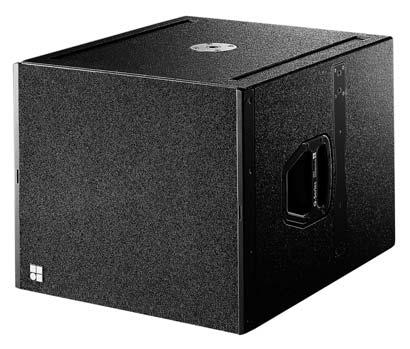
18 The Q subwoofer Q subwoofer The is the subwoofer for the Q-Series and can be used to supplement, Q7 and 0 cabinets in various combinations, either flown or ground stacked. The cabinet is an actively driven bass-reflex design housing a long excursion 18" driver. An M20 threaded flange in the top panel accepts the d&b Loudspeaker stand for the deployment of full range cabinets. Sockets in the front grill and side panels accept Locking pins 8 mm that connect to the Q Splay and Q Front links. The front sockets are specially positioned to also allow the Q Front links to be reversed enabling the lowest loudspeaker to be secured with a downward angle when ground stacked on top of s. Two runners extend from the rear to the front panel of the cabinet protecting the bottom panel against scratching. Two correspondingly shaped recesses are incorporated in the top panel of each cabinet that accept these runners to prevent cabinet movement when stacking s. The cabinet is constructed from marine plywood and has an impact resistant paint finish. The front of the loudspeaker cabinet is protected by a rigid metal grill, covered with a replaceable acoustically transparent foam. The cabinet incorporates a pair of handles, and mounted on the rear panel are two EP5 or NL4 connectors wired in parallel and four heavy duty wheels. 580 [22.83"] 493 [19.40"] cabinet dimensions in mm (inch) 668 [26.30"] 773 [30.42"] System data Frequency response ( 5 db standard)...40 Hz Hz Frequency response ( 5 db 100 Hz mode)...40 Hz Hz Max. sound pressure (1 m, free field) 1... with D db with db Input level (100 db SPL/1 m) dbu Polarity to amplifier INPUT (XLR pin 2: +/3: )...LF: + Loudspeaker data Nominal impedance...8 ohms Power handling capacity (RMS /peak 10 ms)...400/1600 W Components...18 driver Connections...2 x EP5, optional 2 x NL4 Pin assignments...ep5: 3 /4, SenseDrive pin 5 (NL4: 2 +/2 ) Weight...42 kg (92.6 lb) 1 Broadband measurement, pink noise, crest factor 4, peak measurement, linear weighting
19 The D6 and configurations frequency response, standard and 100 Hz modes rear front CSA configuration example with D6 and Selecting mode in the D6 and dual channel amplifiers enables up to two loudspeakers to be driven by the respective channel. In applications with low continuous levels and low ambient temperatures up to three loudspeakers per channel may be connected. For acoustic adjustment the functions 100 Hz and CSA can be selected. If the 100 Hz mode is selected, the upper operating frequency of the system is reduced from 130 Hz to 100 Hz. CSA (Cardioid Subwoofer Array) circuit enables the combination of three or multiples of three subwoofer cabinets into an array that produces exceptional low frequency directivity control. The centre cabinet in a column is physically pointed to the rear, as shown in the drawing opposite and the CSA mode selected on the D6 or channel that powers this cabinet. The forward facing cabinets are driven with a D6 or channel set in the standard mode. The resulting cardioid behaviour of the array will significantly reduce the energy radiated to the rear. For further information please refer to the d&b TI 330 Cardioid Subwoofer Array, which is available for download at The incorporates d&b SenseDrive for accurate control of driver membranes in d&b subwoofers, resulting in an extremely precise bass performance, even at high levels. SenseDrive is only available using the fitted with EP5 connectors and appropriate 5-wire cabling. For further information please refer to the d&b TI 340 SenseDrive, which is available for download at CSA polar pattern


20 The d&b ArrayCalc calculator d&b ArrayCalc calculator For both acoustical and safety reasons Q-Series arrays should be designed using the d&b ArrayCalc simulation tool. It runs exclusively on Microsoft Excel for Windows 1, Version 2000 or higher, or on Microsoft Excel for Mac 2, Version 2004 or higher. ArrayCalc supports d&b audiotechnik loudspeakers from the J-Series and Q-Series; it is used for planning system configurations. This includes defining the quantity and optimum aiming of loudspeakers, calculating subwoofer arrays and the time alignment of these to the main arrays, documenting weights and overall dimensions of arrays as well as producing printable rigging plots and parts lists. ArrayCalc calculates and displays the physical parameters of flown arrays including the mechanical load conditions within a column, load safety information, load values for rigging points and displays warnings should an overload occur. ArrayCalc uses a sophisticated mathematical model synthesizing each loudspeaker s wave front with an array of narrowly spaced point sources. Using complex data (phase information) level distribution is calculated in multiple frequency bands for up to three main audience areas and optionally to side seating tiers. ArrayCalc also calculates resulting dispersion of horizontally arrayed subwoofers at different LF bands and the delay values to achieve a desired far-field coverage. The display of the phase responses of both Main and Sub Array at a selectable test point allows an applicable time alignment to be defined between flown and ground stacked parts of the system. The ArrayCalc software comprises five main sheets; Main Array, Sub Array, Measuring, Rigging and Parts list. It also contains a link to the technical information document TI 385 J-Series and Q-Series system design with ArrayCalc in PDF format. The Main Array sheet that is viewed immediately on opening the software contains fields for entering parameters of the room and array designs, which is then displayed graphically. Up to three different listening planes can be entered, and side extension to planes 2 and 3 can be selected. The top view graphic shows a plan view of the audience areas, the locations of up to two loudspeaker arrays and their horizontal aiming. The Main Array section allows the selection of loudspeaker types, quantities, individual levels and definition of the vertical profile of the array. It includes a side elevation of the complete array, displaying overall mechanical size and rigging information. The Side view shows a cross section through the active listening plane on the horizontal centre axis of one array and the centre axis of each loudspeaker. Any horizontal array aiming angle between 180 and 180 can Flown setup sheet Measuring sheet Rigging plot


21 The d&b ArrayCalc calculator Stacked setup sheet be simulated. The Direct sound level vs. distance/db SPL peak plot shows the peak direct sound level over distance of two selectable frequency bands for all active listening planes. These provide a reliable prediction of the direct sound distribution on the centre axis of the array. The Auto splay function calculates suggested vertical splay angles between the loudspeakers, these can then be adjusted manually. The array EQ function shows the effects of different settings for the amplifier CPL circuit on the response shown in the Direct sound level vs. distance/db SPL plot. The Measuring sheet can be used to define the coordinates of the listening planes using trigonometry and data from a laser inclinometer and a rangefinder. The Rigging plot is a printable sheet that displays the physical parameters and load information such as array dimensions, weights and rigging point locations. The Parts list is a printable sheet providing a complete list detailing all the loudspeakers and rigging components required to configure either a single column or a stereo system, if Sub Array loudspeakers are selected these are also included. The Sub Array sheet allows the definition of up to seventeen subwoofer positions along a front line. In the design section different values may be entered or calculated, the main parameters and applicable values to achieve a desired bass coverage are displayed. The resulting distribution patterns are shown in the SPL mapping section as well a second display showing free and far field polar patterns for selectable LF frequency bands. A test point can be placed in the simulation to show the phase responses of Main and Sub Arrays at one location and time alignment can be applied in order to match the phase response around the crossover region between TOPs and SUBs. For further information please refer to the d&b TI 385 J-Series and Q-Series system design with ArrayCalc, which is available for download at Subwoofer setup sheet 1 Microsoft Excel and Windows are either registered trademarks or trademarks of Micorsoft Corporation in the United States and/or other countries 2 Mac is a trademark of Apple Inc., registered in the U.S. and other countries
22 The Q-Series system block diagram A small sized Q-Series configuration could consist, as shown on the opposite page with the small line array configuration example, of two amplifiers, three loudspeakers, one Q7 loudspeaker and four s. Three s are driven by one channel and one Q7 from the other, this total load is acceptable for one. The Q7 is suspended horizontally with a rotated horn as a downfill and enlarges the vertical coverage in the near field. Four s are driven by the second amplifier configured for s. 0 Laptop or PC running R1 A medium sized Q-Series configuration could consist of three amplifiers, six loudspeakers and six s in CSA mode. Two loudspeakers are driven from one channel using three in total of the channels configured for s. The forward facing s are driven from two channels set in the standard configuration. The rear facing s are power by the remaining channel configured for s with the CSA mode selected. In small or medium sized configurations using music program material a one to one ratio of s to s is recommended. Small basic configuration example D6 R60 CAN-Bus interface CAN-Bus A large sized Q-Series configuration could consist of nine amplifiers, sixteen loudspeakers, two Q7 loudspeakers, twelve s in CSA configurations and three J-SUBs. All the loudspeakers are driven by eight channels configured for s. Two Q7 loudspeakers driven by one channel and used to cover the near field. Eight forward facing s are driven by four channels set in the standard configuration, whilst the rear facing s are driven by two channels configured for s with the CSA mode selected. The frequency response below 40 Hz can be significantly enriched by the use of J-SUBs with INFRA mode selected which are driven by the remaining three channels. As the horizontal constant directivity of a column is maintained down to 400 Hz, two columns of s can be arrayed side by side to provide wider horizontal coverage. A horizontal angle of 50 between two columns provides the best compromise between level and frequency response. The two Q7s are used to cover the near field providing sufficient coverage and level. For further information please refer to the d&b TI 385 J-Series and Q-Series system design with ArrayCalc, which is available for download at
23 The Q-Series system block diagram Q7 Laptop or PC running R1 R60 Small line array configuration example CAN-Bus CAN-Bus interface
24 The Q-Series system block diagram CAN-Bus CAN-Bus interface R60 Laptop or PC running R1 Small ground stacked configuration example CSA CSA Laptop or PC running R1 R60 CAN-Bus interface CAN-Bus Medium flown and ground stacked example
25 The Q-Series system block diagram Laptop or PC running R1 R60 CAN-Bus interface CAN-Bus D6 Q7 Q7 CSA CSA J-SUB CSA CSA J-SUB J-SUB Large flown and ground stacked configuration example
26 The Q-Series product overview Code Description Loudspeakers Z Loudspeaker EP5 connector (including Z5154 Q Rigging set) Z Loudspeaker NL4 connector (including Z5154 Q Rigging set) Z Q7 Loudspeaker EP5 connector Z Q7 Loudspeaker NL4 connector Z Loudspeaker EP5 connector Z Loudspeaker NL4 connector Z Q Subwoofer EP5 connector Z Q Subwoofer NL4 connector Amplifiers Z D6 Amplifier NL4 ( V) Z Amplifier EP5 (115 /230 V) Z Amplifier NL4 (115/230 V) Z Amplifier EP5 (100/200 V) Z Amplifier NL4 (100/200 V) Remote network Z R60 USB to CAN interface Z R70 Ethernet to CAN interface Z RJ 45 M Terminator Z Bopla mounting clamp Z Bopla mounting clamp upright Z R1 Remote control software (available as a download from Z R10 Service software (available as a download from Cables Z2294.xxx MC5 EP5 cable various length Z2291.xxx MC4 NL4 cable various length Z NL4 Extension adapter K MC5 cable unterminated K MC4 cable unterminated Racks E Touring rack 3 RU, 19 DD, shock mounted, handles, window E Touring rack 6 RU, 19 DD, shock mounted, handles, window, wheels E Touring rack 9 RU, 19 DD, shock mounted, handles, window, wheels E Touring rack 2 RU, 19 DD, shock mounted, handles
27 The Q-Series product overview Code Description Cases E Touring case 2 x / Q7/ 0 wheels E Touring case 3 x / Q7/ 0 wheels E Touring case 2 x / Q7/ 0 wheels, Z5161 Q Flying bracket, tray E Touring case 2 x Q Flying frame wheels, flexible cable store, 2 trays Lids E Q Subwoofer wooden lid Accessories Z TV spigot with fixing plate Z TV spigot 02 Z Pipe clamp for Z5010 Z Rota clamp Z Flying adapter 02 Z Flying adapter 03 Z Loudspeaker stand adapter Z Loudspeaker stand with winder Z Loudspeaker stand winder M20 Z Q Swivel bracket Z Qi Horizontal bracket Z MAX Bracket connector Z Q Splay link Z Q Front link Z Locking pins 8 mm (linked in pairs with steel wire) Z Q Rigging set (supplied with includes 2 x Z5151, Z5152 and 4 x Z5153) Z Flying pin 10 mm Z Q Hoist connector chain (supplied with 2 x E6507 1t Shackles) Z Q Flying adapter Z Q Flying frame Z Q Load adapter Z Q Flying bracket Q M10 Safety eyebolt E t Shackle Misc. Z Anti-slip coating 1 kg /2.2 lb Z Standard cabinet paint 1 kg /2.2 lb
The Q-Series Q-Series Q-SUB D12 Q1, Q7 Q10 d&b Remote network
 The Q-Series The Q-Series The Q-Series continues the established d&b audiotechnik approach to the design and manufacture of loudspeaker systems, adding another dimension to d&b s maxima. It is designed
Contents. The d&b System reality The Q-Series The Q-Series product photographs The Q1 and Qi1 loudspeakers... 6
 The Q-Series Contents The d&b System reality... 3 The Q-Series... 4 The Q-Series product photographs... 5 The and loudspeakers... 6 The Q7 and Qi7 loudspeakers... 7 The 0 and 0 loudspeakers... 8 The Q,
C7-TOP Manual (3.0E)
") C7-TOP Manual (3.0E) References in the manual WARNING! CAUTION! IMPORTANT! This refers to a potentially dangerous situation which may lead to personal injury. This refers to a potentially dangerous situation
C7-TOP Manual (3.0E) References in the manual WARNING! CAUTION! IMPORTANT! This refers to a potentially dangerous situation which may lead to personal injury. This refers to a potentially dangerous situation
Symbols on the equipment. WARNING! Dangerous voltage!
 Q10 Manual (1.4 EN) Symbols on the equipment Please refer to the information in the operating manual. WARNING! Dangerous voltage! Contents Safety precautions...3 Information regarding use of loudspeakers...3
Symbols on the equipment. WARNING! Dangerous voltage!
 Q7 Manual (2.4 EN) Symbols on the equipment Please refer to the information in the operating manual. WARNING! Dangerous voltage! Contents Safety precautions...3 Information regarding use of loudspeakers...3
C4-TOP Manual (3.0E)
") C4-TOP Manual (3.0E) References in the manual WARNING! CAUTION! IMPORTANT! This refers to a potentially dangerous situation which may lead to personal injury. This refers to a potentially dangerous situation
C4-TOP Manual (3.0E) References in the manual WARNING! CAUTION! IMPORTANT! This refers to a potentially dangerous situation which may lead to personal injury. This refers to a potentially dangerous situation
The J-Series d&b J-Series J-SUB J-INFRA D12 J12 d&b Remote network
 The J-Series The J-Series The d&b J-Series continues the established d&b audiotechnik approach to the design and manufacture of loudspeaker systems. It is intended for use in large-scale sound reinforcement
WARNING! CAUTION! IMPORTANT! References in the manual
 E3 Manual (3.0E) References in the manual WARNING! CAUTION! IMPORTANT! This refers to a potentially dangerous situation which may lead to personal injury. This refers to a potentially dangerous situation
C4-TOP CAUTION! NL n.c. C4-TOP Data Sheet. Connector wiring. Speakon- NL4 and EP-5 pin assignments. Passive Crossover
 Data Sheet Safety precautions Never stand in the immediate vicinity of loudspeakers driven at a high level. Professional loudspeaker systems are capable of causing a sound pressure level detrimental to
E1 controller module switches
 E1 Data Sheet Safety precautions Never stand in the immediate vicinity of loudspeakers driven at a high level. Professional loudspeaker systems are capable of causing a sound pressure level detrimental
Q-SUB Manual (2.3 EN)
") Q-SUB Manual (2.3 EN) Symbols on the equipment Please refer to the information in the operating manual. WARNING! Dangerous voltage! Contents Safety precautions...3 Information regarding use of loudspeakers...3
Q-SUB Manual (2.3 EN) Symbols on the equipment Please refer to the information in the operating manual. WARNING! Dangerous voltage! Contents Safety precautions...3 Information regarding use of loudspeakers...3
WARNING! CAUTION! IMPORTANT! References in the manual. This refers to a p otentially dangerous situation which may lead to personal injury.
 M2 Manual (5.0E) References in the manual WARNING! CAUTION! IMPORTANT! This refers to a p otentially dangerous situation which may lead to personal injury. This refers to a p otentially dangerous situation
MAX12 Manual (5.1 EN)
") MAX12 Manual (5.1 EN) Symbols on the equipment Please refer to the information in the operating manual. WARNING! Dangerous voltage! Contents Safety precautions...3 Information regarding use of loudspeakers...3
MAX12 Manual (5.1 EN) Symbols on the equipment Please refer to the information in the operating manual. WARNING! Dangerous voltage! Contents Safety precautions...3 Information regarding use of loudspeakers...3
B2-SUB Manual (3.1 EN)
") B2-SUB Manual (3.1 EN) Symbols on the equipment Please refer to the information in the operating manual. WARNING! Dangerous voltage! Contents Safety precautions...3 Information regarding use of loudspeakers...3
B2-SUB Manual (3.1 EN) Symbols on the equipment Please refer to the information in the operating manual. WARNING! Dangerous voltage! Contents Safety precautions...3 Information regarding use of loudspeakers...3
Symbols on the equipment. WARNING! Dangerous voltage!
 E6 Manual (1.0 EN) Symbols on the equipment Please refer to the information in the operating manual. WARNING! Dangerous voltage! Contents Safety precautions...3 Information regarding use of loudspeakers...3
C6-MON CAUTION! EP NL n.c. C6-MON Data Sheet. Passive Crossover. Connector wiring. Speakon- NL4 and EP-5 pin assignments
 C6-MON Data Sheet Safety precautions Never stand in the immediate vicinity of loudspeakers driven at a high level. Professional loudspeaker systems are capable of causing a sound pressure level detrimental
E-Series. d&b E-Series
 E E-Series d&b E-Series Contents The d&b System reality... 4 The E-Series... 6 The E4 loudspeaker... The E5 loudspeaker... The E6 loudspeaker...2 The E8 loudspeaker...3 The E2 loudspeaker and E2-D loudspeaker...4
The J-Series d&b J-Series J-SUB D12 J12 J-Series
 The J-Series The J-Series The d&b J-Series continues the established d&b audiotechnik approach to the design and manufacture of loudspeaker systems. It is intended for use in large-scale sound reinforcement
Contents. The d&b System reality The xs-series The 8S loudspeaker The 10S and 10S-D loudspeakers...13
 xs xs-series Contents The d&b System reality... 4 The xs-series... 6 The 4S loudspeaker... The S loudspeaker...11 The 8S loudspeaker...12 The S and S-D loudspeakers...13 The 12S and 12S-D loudspeakers...14
Contents. The d&b System reality The Stage monitors The M2 monitor The M4 monitor The Stage monitor cases...
 M Monitors Contents The d&b System reality.... 4 The Stage monitors.... 6 The MAX2 monitor....1 The M6 monitor....11 The M4 monitor....12 The M2 monitor....13 The Stage monitor cases....14 The MAX2 mounting
Ti10 Manual (1.0 EN)
") Ti10 Manual (1.0 EN) Symbols on the equipment Please refer to the information in the operating manual. WARNING! Dangerous voltage! Contents Safety precautions...3 Information regarding use of loudspeakers...3
Ti10 Manual (1.0 EN) Symbols on the equipment Please refer to the information in the operating manual. WARNING! Dangerous voltage! Contents Safety precautions...3 Information regarding use of loudspeakers...3
C4-SUB Manual (3.0E)
") C4-SUB Manual (3.0E) References in the manual WARNING! CAUTION! IMPORTANT! This refers to a potentially dangerous situation which may lead to personal injury. This refers to a potentially dangerous situation
C4-SUB Manual (3.0E) References in the manual WARNING! CAUTION! IMPORTANT! This refers to a potentially dangerous situation which may lead to personal injury. This refers to a potentially dangerous situation
Contents. d&b V-Series 3
 V V-Series Contents The d&b System reality.... 4 The V-Series.... 6 The V7P and Vi7P loudspeakers.... The VP and ViP loudspeakers....11 The V-GSUB and Vi-GSUB....12 The V7P, VP and V-GSUB transport accessories.....13
The E-Series E-Series D12 E-PAC E-Series E12-SUB
 The E-Series The E-Series The E-Series loudspeaker range from d&b audiotechnik comprises the smallest cabinets within the product range and are systems that are predominantly used as single units or in
Contents. The d&b System reality The E-Series The E8 loudspeaker The E12/E12-D loudspeakers The E15X subwoofer...
 E E-Series Contents The d&b System reality... 4 The E-Series... 6 The E4 loudspeaker... The E5 loudspeaker...11 The E6 loudspeaker...12 The E8 loudspeaker...13 The E12/E12-D loudspeakers...14 The E12X
General information Keep this document with the product or in a safe place so that it is available for future reference.
 xs 8S Manual 1.4 en General information 8S Manual Version: 1.4 en, 10/2018, D2608.EN.01 Copyright 2018 by d&b audiotechnik GmbH; all rights reserved. Keep this document with the product or in a safe place
Symbols on the equipment. WARNING! Dangerous voltage!
 Qi1 Manual (1.3 EN) Symbols on the equipment Please refer to the information in the operating manual. WARNING! Dangerous voltage! Contents Safety precautions...3 Information regarding use of loudspeakers...3
2 Data Sheet. 2/B1 rigging
 2 Data Sheet Safety precautions Never stand in the immediate vicinity of loudspeakers driven at a high level. Professional loudspeaker systems are capable of causing a sound pressure level detrimental
J-INFRA Manual (1.1 EN)
") J-INFRA Manual (1.1 EN) Symbols on the equipment Please refer to the information in the operating manual. WARNING! Dangerous voltage! Contents Safety precautions...3 Information regarding use of loudspeakers...3
J-INFRA Manual (1.1 EN) Symbols on the equipment Please refer to the information in the operating manual. WARNING! Dangerous voltage! Contents Safety precautions...3 Information regarding use of loudspeakers...3
V-Series. d&b V-Series 1
 V V-Series d&b V-Series Contents The d&b System reality... 4 The V-Series... 6 The V7P loudspeaker and Vi7P loudspeaker... The VP loudspeaker and ViP loudspeaker... The V-GSUB and Vi-GSUB...2 The V7P,
E15-BX CAUTION! IMPORTANT!
 E15-BX Data Sheet Safety precautions Never stand in the immediate vicinity of loudspeakers driven at a high level. Professional loudspeaker systems are capable of causing a sound pressure level detrimental
Symbols on the equipment. WARNING! Dangerous voltage!
 Qi7 Manual (1.2 EN) Symbols on the equipment Please refer to the information in the operating manual. WARNING! Dangerous voltage! Contents Safety precautions...3 Information regarding use of loudspeakers...3
Ci80 Manual (4.1 EN)
") Ci80 Manual (4.1 EN) Symbols on the equipment Please refer to the information in the operating manual. WARNING! Dangerous voltage! Contents Safety precautions...3 Information regarding use of loudspeakers...3
Ci80 Manual (4.1 EN) Symbols on the equipment Please refer to the information in the operating manual. WARNING! Dangerous voltage! Contents Safety precautions...3 Information regarding use of loudspeakers...3
D Amplifiers Software
 D Amplifiers Software Contents The d&b System reality... 4 The d&b workflow... 6 The d&b ArrayCalc simulation software... 8 The d&b Remote network...10 d&b Remote network topology...12 The D6, and amplifiers...14
D Amplifiers Software
 D Amplifiers Software Contents The d&b workflow... 6 The d&b ArrayCalc simulation software... 8 The d&b Remote network...10 d&b Remote network topology...12 The D6,, D20 and amplifiers...14 The D6 amplifier...18
Contents. The d&b System reality The J-Series The J8 loudspeaker The J12 loudspeaker The J subwoofer...12
 J J-Series Contents The d&b System reality... 4 The J-Series... 6 The loudspeaker...10 The loudspeaker...11 The J subwoofer...12 The J-INFRA subwoofer...13 The J-Series rigging system...14 The J-Series
Ci7-SUB Manual (2.1 EN)
") Ci7-SUB Manual (2.1 EN) Symbols on the equipment Please refer to the information in the operating manual. WARNING! Dangerous voltage! Contents Safety precautions...3 Information regarding use of loudspeakers...3
Ci7-SUB Manual (2.1 EN) Symbols on the equipment Please refer to the information in the operating manual. WARNING! Dangerous voltage! Contents Safety precautions...3 Information regarding use of loudspeakers...3
D Amplifiers Software
 D Amplifiers Software Contents The d&b workflow.... 6 The d&b ArrayCalc simulation.... 8 The d&b Remote network....10 d&b Remote network topology....12 The DS10 Audio network bridge....14 The d&b amplifiers....16
APEX ARRAY APEX 28HA / APEX 18SA
 APEX ARRAY APEX 28HA / APEX 18SA 16 18 19 APEX 28HA / APEX 18SA are Active Speakers for professional use, they can be used in following electro- magnetic environment: residential, commercial and light
VUE al-4 Subcompact Line Array System -4 Acoustic Element & V4 Systems Engine Specification Sheet A Whole New World Of Possibilities lim Da ina
 VUE al-4 Acoustic Element & Systems Engine A Whole New World Of Possibilities ry ina m a eli at Pr D The utilizes advanced technologies to extract unparalleled performance from an ultra-compact and highly
IBIZA ONE Series IBZA10
 IBIZA ONE Series IBIZA ONE Series is the ultimate reference for dance clubs environments. A combination of high-end audio, sound quality, stunning aesthetics, extreme sound pressure level and reliability.
SOUND PROJECTS Jonkerweg PM Hilversum The Netherlands Phone +31 (0) Fax +31 (0)
 Fax +31 (0)") S O U N D P R O J E C T S PRODUCT INFORMATION S-SERIES LINE ARRAY SYSTEMS SOUND PROJECTS Jonkerweg 17-19 1217 PM Hilversum The Netherlands Phone +31 (0)35 6213233 Fax +31 (0)35 6215455 V1.2 16-4-2004 Product
S O U N D P R O J E C T S PRODUCT INFORMATION S-SERIES LINE ARRAY SYSTEMS SOUND PROJECTS Jonkerweg 17-19 1217 PM Hilversum The Netherlands Phone +31 (0)35 6213233 Fax +31 (0)35 6215455 V1.2 16-4-2004 Product
RIGS STACKS ROCKS ROLLS
 RIGS STACKS ROCKS ROLLS Page 1 www.clairbrothers.com One Clair Boulevard, Manheim, PA 17545 717.665.4000 Key Features The kit Series loudspeakers are full range, high output loudspeakers ideal for speech
D AmplifiersSoftware
 D Amplifiers Software Contents The d&b System reality... 4 The d&b Workflow... 6 The d&b ArrayCalc simulation software... 8 The d&b NoizCalc immission modelling software...0 The d&b Remote network...2
ARRAY Series. MINIArray / LA208 / LA122 LA312 / SW118M / SW218V APPLICATIONS
 ARRAY Series LA122 The Tecnare Array Series is a fully integrated line of self-powered DSP controlled loudspeakers that merge the singular advantages of array technology, with the application of computer
SOUND PROJECTS Jonkerweg PM Hilversum The Netherlands Phone +31 (0) Fax +31 (0)
 Fax +31 (0)") S O U N D P R O J E C T S PRODUCT INFORMATION SP3-60 SOUND PROJECTS Jonkerweg 17-19 1217 PM Hilversum The Netherlands Phone +31 (0)35 6213233 Fax +31 (0)35 6215455 SP3-60 The SOUND PROJECTS 3-60 is a full-range
S O U N D P R O J E C T S PRODUCT INFORMATION SP3-60 SOUND PROJECTS Jonkerweg 17-19 1217 PM Hilversum The Netherlands Phone +31 (0)35 6213233 Fax +31 (0)35 6215455 SP3-60 The SOUND PROJECTS 3-60 is a full-range
IBIZA ONE Series IBZA1561
 IBIZA ONE Series IBIZA ONE Series is the ultimate reference for dance clubs environments. A combination of high-end audio, sound quality, stunning aesthetics, extreme sound pressure level and reliability.
SOUND PROJECTS Jonkerweg PM Hilversum The Netherlands Phone +31 (0) Fax +31 (0)
 Fax +31 (0)") S O U N D P R O J E C T S PRODUCT INFORMATION X-ACT SOUND PROJECTS Jonkerweg 17-19 1217 PM Hilversum The Netherlands Phone +31 (0)35 6213233 Fax +31 (0)35 6215455 X-ACT / SP15 SYSTEM SOUND PROJECTS X-act
S O U N D P R O J E C T S PRODUCT INFORMATION X-ACT SOUND PROJECTS Jonkerweg 17-19 1217 PM Hilversum The Netherlands Phone +31 (0)35 6213233 Fax +31 (0)35 6215455 X-ACT / SP15 SYSTEM SOUND PROJECTS X-act
DESIGNED & TUNED IN THE USA CATALOGUE 2018 ALTOPROFESSIONAL.COM
 DESIGNED & TUNED IN THE USA CATALOGUE 2018 TS3 S E R I E S The all-new Alto Professional TS3 Series of professional loudspeakers deliver solutions for every performance and installation challenge. With
Data sheet AT-35 active. Arc-Series Architectural Sound Design.
 Data sheet AT-35 active Arc-Series Architectural Sound Design. AT-35 active loudspeaker The Fohhn AT-35 active is equipped with the latest generation of 12 /1 neodymium speakers. AT-35 active is equipped
CBT 100LA Constant Beamwidth Technology
 CBT LA Constant Beamwidth Technology Line Array Column Loudspeaker with Sixteen 5 mm (2 in) Drivers Key Features: Patent-pending Constant Beamwidth Technology provides constant directivity up to the highest
Compact Sound Reinforcement System
 www.nexo-sa.com Complete directivity control comes to compact power. With a unique user-rotatable horn that lets users quickly select between two preset directivity options, ID24 brings unparalleled flexibility
datasheet TFA-600HDP FLEX ARRAY SERIES ENGINEERING INFORMATION FEATURES APPLICATIONS Digitally self-powered Line array or virtual point source element
 FLEX ARRAY SERIES ENGINEERING INFORMATION datasheet Flex Array series is a high performance modular loudspeaker system designed for use in a variety of medium scale line array or virtual point source sound
Data sheet PT-9 WaveLine. Perform- Series. Line-Array Systems.
 Data sheet PT-9 WaveLine Perform- Series Line-Array Systems. PT-9 WaveLine The Fohhn WaveLine ist a very high powerful line array System. PT-9 module, twin-coaxial, fully horn-loaded, 2x 10 neodymium,
Compact Sound Reinforcement System
 NEXO S. A. Parc D Activité du Pré de la Dame Jeanne B.P.5 60128 PLAILLY France Tel: +33 (0)3 44 99 00 70 Fax: +33 (0)3 44 99 00 30 E-mail: info@nexo.fr Compact Sound Reinforcement System www.nexo-sa.com
KI-215-SMA-II DESIGNED AND MADE IN THE USA USING DOMESTIC AND IMPORTED COMPONENTS SPECIFICATIONS PRODUCT OVERVIEW FEATURES
 KI-215-SMA-II DESIGNED AND MADE IN THE USA USING DOMESTIC AND IMPORTED COMPONENTS In 1946, Paul W Klipsch, genius & maverick, hand-built his first loudspeaker in a tin shed with the intention of bringing
D12 Amplifier Hardware manual (2.0E)
") D12 Amplifier Hardware manual (2.0E) References in the manual WARNING! CAUTION! IMPORTANT! Note: This refers to a potentially dangerous situation which may lead to personal injury. This refers to a potentially
D12 Amplifier Hardware manual (2.0E) References in the manual WARNING! CAUTION! IMPORTANT! Note: This refers to a potentially dangerous situation which may lead to personal injury. This refers to a potentially
KI-362-SMA-II DESIGNED AND MADE IN THE USA USING DOMESTIC AND IMPORTED COMPONENTS SPECIFICATIONS PRODUCT OVERVIEW FEATURES APPLICATIONS
 KI-SMA-II DESIGNED AND MADE IN THE USA USING DOMESTIC AND IMPORTED COMPONENTS In 194, Paul W Klipsch, genius & maverick, hand-built his first loudspeaker in a tin shed with the intention of bringing live
Data sheet AT-661w. Arc-Series. Architectural Sound Design.
 Data sheet AT-661w Arc-Series Architectural Sound Design. AT-661w loudspeaker VSM The Fohhn AT-661w is a fullrange outdoor system. The system is fully weatherproof, with a robust housing constructed from
KI-362-SMA-II MADE IN AMERICA: HOPE, ARKANSAS SPECIFICATIONS PRODUCT OVERVIEW FEATURES APPLICATIONS TRAPEZOIDAL 15 3-WAY LOUDSPEAKER
 KI-SMA-II MADE IN AMERICA: HOPE, ARKANSAS In 194, Paul W Klipsch, genius & maverick, hand-built his first loudspeaker in a tin shed with the intention of bringing live music into his living room. Remember
LA8 Amplified Controller
 LA8 Amplified Controller 5 6 7 8 LA8 Amplified Controller main feature identifications: 4 3 2 1 9 10 1 On/Off Switch 2 Anti-Dust Cover 3 Input selection + Menu keys 4 Output selection keys 5 LED clip and
Data sheet FC-9 DSP system controller. Amp Contoller-Series DSP-Amplifiers + DSP-Controller.
 Data sheet FC-9 DSP system controller Amp Contoller-Series DSP-Amplifiers + DSP-Controller. FC-9 DSP system controller The Fohhn FC-9 digital DSP system controller was especially designed for fixed installations
LSP 500 PRO. Wireless Integrated Professional Audio System FEATURES ARCHITECT S SPECIFICATION
 Wireless Integrated Professional Audio System FEATURES Complete wireless integrated PA system Wireless control for up to 20 LSP 500 PRO via ipad or Windows device Integrated Bluetooth audio streaming Integrated
ESM Series User Guide
 ESM Series User Guide ESM26 ESM12 The future of sound. Made perfectly clear. At KV2 Audio our vision is to constantly develop technologies that eliminate distortion and loss of information providing a
MAXIMUM SPL3 COVERAGE
 KI-39-SMA-II DESIGNED AND MADE IN THE USA USING DOMESTIC AND IMPORTED COMPONENTS In 194, Paul W Klipsch, genius & maverick, hand-built his first loudspeaker in a tin shed with the intention of bringing
VP SERIES Active compact line array system V2208P V1212P V1218P
 VP SERIES Active compact line array system V2208P V1212P V1218P We've got the power, we are active! SAE Audio has a great experience developing professional audio products for over 15 years. Being the
SOUND PROJECTS Karperweg SN Almere The Netherlands Phone +31 (0) Fax +31 (0)
 Fax +31 (0)") S O U N D P R O J E C T S GENERAL INFO AND OPERATION MANUAL FOR SPX SERIES SOUND PROJECTS Karperweg 16 1317 SN Almere The Netherlands Phone +31 (0)36 53 94 570 Fax +31 (0)36 53 00 578 Contents LINE-ARRAY
S O U N D P R O J E C T S GENERAL INFO AND OPERATION MANUAL FOR SPX SERIES SOUND PROJECTS Karperweg 16 1317 SN Almere The Netherlands Phone +31 (0)36 53 94 570 Fax +31 (0)36 53 00 578 Contents LINE-ARRAY
F O R U M S E R I E S
 R E V.1 F O R U M S E R I E S INSTRUCTION BOOKLET MODELS FORUM 8, 10, 12, 15, 8M, 15M & FORUM 12SUB & 15SUB F O R T H E C L O S E S T A P P R O A C H T O T H E O R I G I N A L S O U N D TABLE OF CONTENTS
C200 PRECISION PASSIVE LOUDSPEAKER. FEATURES: 2-way portable Precision Passive loudspeaker system APPLICATIONS
 C200 Featuring legendary Mackie sound quality and durability, the lightweight C Series 2-way Precision Passive loudspeakers deliver optimum performance in portable PA, stage monitor and permanent installation
user manual 1.0 (EN)
") X8 user manual 1.0 (EN) Document reference: X8 user manual (EN) version 1.0 Distribution date: September 24, 2015 2015 L-ACOUSTICS. All rights reserved. No part of this publication may be reproduced or
X8 user manual 1.0 (EN) Document reference: X8 user manual (EN) version 1.0 Distribution date: September 24, 2015 2015 L-ACOUSTICS. All rights reserved. No part of this publication may be reproduced or
TECHNICAL DATA SHEET. FreeSpace DS 100SE. Loudspeaker. Product Overview. Key Features. Product Information. Applications
 Product Overview The Bose FreeSpace DS 100SE loudspeaker is a high-performance, surface-mount loudspeaker designed for foreground music and speech reproduction in a wide range of commercial applications,
D12 Amplifier Software manual (5.2EN) (Firmware V2.x.x)
 (Firmware V2.x.x)") D12 Amplifier Software manual (5.2EN) (Firmware V2.x.x) General Information D12 Amplifier Software manual (Firmware V2.x.x) Version 5.2EN, 02/2008, D2013.E.05 Copyright 2008 by d&b audiotechnik AG; all
D12 Amplifier Software manual (5.2EN) (Firmware V2.x.x) General Information D12 Amplifier Software manual (Firmware V2.x.x) Version 5.2EN, 02/2008, D2013.E.05 Copyright 2008 by d&b audiotechnik AG; all
The StudioLive 18sAI is the
 1,000 watt Class D amplifier Universal switch mode power supply with power-factor correction 24-bit floating point, 96 khz DSP Temperature and overvoltage protection Excursion Limiting Wireless and wired
Orbis MU 21. Digital Delegate Microphone Unit with Loudspeaker Order #
 Digital Delegate Microphone Unit with Loudspeaker Order # 725.706 Supplied without gooseneck microphone FEATURES Coated plastic housing with metal bottom plate Inserts made of optically hardened acrylic
i-5 TM Full Range Vertical Array Loudspeaker
 i-5 TM Full Range Vertical Array Loudspeaker Designed for medium-to-large venues and outdoor applications, the i-5 is Clair s latest innovation in large format line array system technology. Built from
KS28. user manual (EN)
") KS28 user manual (EN) Document reference: KS28 user manual (EN) version 1.0 Distribution date: April 4, 2016 2016 L-Acoustics. All rights reserved. No part of this publication may be reproduced or transmitted
KS28 user manual (EN) Document reference: KS28 user manual (EN) version 1.0 Distribution date: April 4, 2016 2016 L-Acoustics. All rights reserved. No part of this publication may be reproduced or transmitted
TECHNICAL DATA SHEET DS 16S/DS 16SE. FreeSpace. Loudspeakers. Product Overview. Key Features. Product Information. Applications
 Product Overview Bose FreeSpace DS 16S and FreeSpace DS 16SE loudspeakers are high-performance, surfacemount loudspeakers designed for background music and speech reproduction in a wide range of commercial
HPA4202 1/5. 2-Channel High Power Multi-Impedance Amplifier. General Description. Features. Applications. AtlasIED.com. HPA4202 Front.
 1/5 HPA4202 2-Channel High Power Multi-Impedance Amplifier Features 70.7V/100V and 2Ω, 4Ω, and 8Ω Output 100V 70.7V 8Ω 2 x 1200W 4Ω 2Ω 2 x 2500W 8Ω BRIDGED 1 x 3800W 4Ω BRIDGED 1 x 4800W Balanced Inputs
Data sheet AS-20 / ASP-20. Arc- Series. Architectural Sound Design.
 Data sheet AS-20 / ASP-20 Arc- Series Architectural Sound Design. AS- 20 / ASP-20 subwoofer system Fohhn AS-20 / ASP-20 Compact bass system, 400 W, 1 12, vented design. Description The Fohhn AS-20 is a
EQUALIZER BACKGROUND. PRE-AMP Line Driver
 INTRODUCTION Congratulations on your purchase of your new pre amplifier-equalizer. Our sonic excellence is considered our most important objective. Your selection of this component tells us you desire
Data sheet AT-40. Arc-Series Architectural Sound Design.
 Data sheet AT-40 Arc-Series Architectural Sound Design. AT-40 loudspeaker The Fohhn AT-40 is an etremely powerful, high-capacity speaker system in a comparatively compact housing. It combines efficiency,
TitanONE Smart Mainframe Power Amplifier
 1/7 TitanONE Smart Mainframe Power Amplifier T112 General Description The AtlasIED TitanONE T112 Smart Mainframe Power Amplifier provides the latest signal automation, processing and amplification technologies
The Future of Sound. Made Perfectly Clear.
 ESM Series User Guide ESM26 ESM12 The Future of Sound. Made Perfectly Clear. At KV2 Audio our vision is to constantly develop technologies that eliminate distortion and loss of information providing a
Features. General Specifications. Surface Mount Speaker VXS5/VXS5W. Sophisticated sound and design for matching any application. Technical Data Sheet
 Features Sophisticated sound and design for matching any application. Series comprises two full-range models and two subwoofers available in either black or white. Features newly customized transducers
DATA SHEET DEVIO SCR-20 CONFERENCING HUB
 DATA SHEET DEVIO SCR-20 CONFERENCING HUB The Devio SCR-20 is a conferencing hub that provides users with exceptional AV experiences when using web-based conferencing systems. Intended for huddle rooms
VIPEDIA-12. Cameo specification sheet. Product Description
 Product Description Pro-Sound quality Two RJ45 Ethernet IP ports 12 analogue audio inputs 12 dual A&B analogue audio outputs 20dB outputs for intelligent speakers Advanced energy management 30 minutes
ULTRA-COMPACT MULTI-CELLULAR LOUDSPEAKER ARRAY
 ULTRA-COMPACT MULTI-CELLULAR LOUDSPEAKER ARRAY With the introduction of the award-winning MLA and MLA Compact systems, Martin Audio turned the line array world on its head. Different in concept to line
MU12Ba. User Manual. MU Series Pro Loudspeaker System. 12" Active Subwoofer. UM- MU12Ba v er A
 12" Active Subwoofer MU Series Pro Loudspeaker System User Manual UM- - 20090801 v er A SAFETY INSTRUCTIONS PLEASE READ THIS MANUAL FIRST Thanks for buying products. Read this manual first as it will help
XENO 8. User & Installation Manual.
 XENO 8 User & Installation Manual www.audac.eu 2 Introduction 8 Full range loudspeaker cabinet The XENO series is a loudspeaker range specifically designed for fixed audio installations in modern environments,
VSX 8.2BP. Stunning Performance
 ation Applications Compact band pass subwoofer for portable and installation applications 400 Watts continuous, 1,600 Watts peak power Twin 8" bass drivers for extended low frequency system response to
FAQ. Thump Series. What models are featured in the Thump Series?
 Thump Series http:///products/thump What models are featured in the Thump Series? The Thump Series will consist of four powered loudspeakers and one powered subwoofer: Thump12A 1300W 12" Powered Loudspeaker
Orbis MU 41. Digital Flush Mount Delegate Microphone Unit Order #
 Digital Flush Mount Delegate Microphone Unit Order # 725.722 Optional CA OL loudspeaker module, not included Table installation supplied without gooseneck microphone FEATURES High-quality flush mounting
DVS 8T # # Superb Point-Source Performance
 Product Information Document Full range surface-mount loudspeaker for indoor and outdoor installation applications 7 Watts continuous, 28 Watts peak power 8" mineral loaded polypropylene driver with nitrile
AMT-12 AMT-15. Professional Loudspeakers. Installation and Use Manual
 AMT-12 AMT-15 Professional Loudspeakers Installation and Use Manual 2008 Bogen Communications, Inc. Specifications subject to change without notice. 54-2183-01C 0907 Table of Contents Introduction 2 Speaker
CMS 503ICT BM. Optimised for Installation
 Product Information Document Full range ceiling loudspeaker for installation applications 50 Watts continuous, 200 Watts peak power 5" ICT (Inductive Coupling Technology) point source driver for extended
CMS 603ICT BM. Optimised for Installation
 Product Information Document Full range ceiling loudspeaker for installation applications 60 Watts continuous, 240 Watts peak power 6" ICT (Inductive Coupling Technology) point source driver for extended
Analog Two-Way Bi-Amplified Active Monitors
 Analog Two-Way Bi-Amplified Active Monitors 6010 APM Compact, Two-Way Active Loudspeaker. Solid die-cast aluminium MDE cabinet (Minimum Diffraction Enclosure) cabinet including DCW protection grills and
GEOSOFT 2.0. User Manual
 GEOSOFT 2.0 User Manual Geosoft2 (v1.1.5) User Manual Date: 27/06/2007 CONTENTS INTRODUCTION...6 MENU SELECTIONS...7 FILE MENU...7 New...7 Open...7 Save...7 Save As...7 Import Geosoft 1 Projects...7 Export...7
SL4210/SL4210-WH. Ultra-Compact, Surface-Mounted 10-Watt Loudspeaker
 Features High-performance, surface-mountable loudspeaker for foreground music, AV playback and distributed sound Exceptional sound quality with wide frequency bandwidth and uniform dispersion 10-Watt,
CS-1 Active Full Range Integrated Commercial Audiovisual System
 Active Full Range Integrated Commercial Audiovisual System User Manual SAFETY INSTRUCTIONS PLEASE READ THROUGH THIS MANUAL FIRST BEFORE OPERATING THE CS-1 SYSTEM. Thank you for purchasing this Beta3 product