Contents. The d&b System reality The Q-Series The Q-Series product photographs The Q1 and Qi1 loudspeakers... 6
|
|
|
- Kenneth Alexander
- 5 years ago
- Views:
Transcription

1 The Q-Series
2 Contents The d&b System reality... 3 The Q-Series... 4 The Q-Series product photographs... 5 The and loudspeakers... 6 The Q7 and Qi7 loudspeakers... 7 The 0 and 0 loudspeakers... 8 The Q, Qi and QiCSA subwoofers... 9 The rigging system...10 The rigging examples...11 The Q7/0 mounting accessories...12 The Q7/0 mounting examples...13 The Qi rigging system...14 The rigging examples...15 The Qi rigging system...16 The Qi7/0 rigging examples...16 The Qi7/0 mounting and rigging accessories and examples...17 The d&b ArrayCalc calculator...18 The D6 and amplifiers...20 The D6 and amplifier data...21 The operation with D6 and amplifiers...22 The Q-Series frequency responses...23 The Q-Series configuration examples...24 The Qi loudspeakers Weather Resistant and Special Colour options...29 The D6 and amplifiers installation...30 The D6 and amplifiers power consumption and power loss...31 The d&b Remote network...32 The d&b Remote software...33 The Q-Series product overview d&b Q-Series
3 The d&b System reality As the name implies a d&b system is not just a loudspeaker. Nor is it merely a sum of the components: loudspeakers, control electronics, mechanical accessories and remote control. Right from the outset the d&b audiotechnik approach was to build integrated sound reinforcement systems that were more than the sum of their parts. Each element is tightly specified, precisely aligned and carefully integrated to achieve maximum possible performance, along with neutral sound characteristics. At the same time d&b offers integrated training, technical information, expert service and support, as well as a knowledgeable distribution network, so that the same optimal acoustic result is achieved by every system anywhere, at any time. d&b Q-Series 3
4 The Q-Series The Q-Series embodies the d&b holistic approach to sound reinforcement solutions: integrating loudspeakers, electronics, mechanical deployment assemblies, remote control functions and setup design tools for precise calculation of array performance. Control of dispersion behaviour is a particular fixation at d&b, while at the same time keeping the size and weight of systems to an absolute minimum. The Q-Series maintains the d&b specific combination of a neutral, intelligible sound character that is clear and transparent even at high sound pressure levels providing the engineer with an efficient, effortless tool and a neutral platform. The Q-Series loudspeakers are the perfect option for speech and music in many theatre and presentation situations, live television and orchestral shows, situations where multiple open microphones are used and considerable gain before feedback is an absolute requirement. The transparency, bandwidth, high power and headroom capabilities, also make them ideal for any type of amplified music. The scope of applications is intentionally broad, ranging from single loudspeakers right through to larger multiple cabinet arrays. To this end a variety of technologies are used: conventional rotatable CD horns, dipolar driver arrangements, low compression vented designs with high excursion drivers and toroidal wave shaping devices, all integrated using line array principals. The Q and Qi loudspeakers are designed for mobile and installed applications respectively, the Qi versions differing only in cabinet construction and mounting hardware. The Q loudspeakers are designed for a wide range of small to medium scale applications with a clear perspective to provide mobile, flexible, configurable array solutions to the most arduous sound reinforcement situations. The d&b ArrayCalc calculator predicts the performance of arrays, enabling simple and accurate system planning. The Qi loudspeakers are intended for permanently installed performance spaces where the specification is rider driven by the artist or mix engineer s preferences. Both the Qi cabinets and mounting hardware can be properly colour matched to interior designs, are mechanically adapted for installation use and can provide protection in climatically hostile environments. The 2-way passively crossed over /, Q7/Qi7 and 0/0 loudspeaker cabinets sharing the same physical size, shape, rigging and driver compliment. The highest degree of constant directivity is maintained using a large frequency overlap through the crossover range, while the recessed dipolar positioning of the two 10 low frequency drivers mechanically time aligns these with the 1.3 exit HF driver. The / HF drivers are fitted with a toroidal wave shaping device, which have a 75 (h) and 75 x 15 (h x v) dispersion pattern respectively, the resulting curved coherent wave front allows vertical arrays of multiple cabinets to be constructed. The Q7/Qi7 and 0/0 loudspeakers also use a 1.3 HF driver fitted to rotatable 75 x 40 and 110 x 40 (h x v) constant directivity horns respectively allowing them to be configured for use both vertically or horizontally. When deployed upright, the Q7/Qi7 and 0/0 are accurate stand-alone full range loudspeakers with vertical directivity control extending approximately one octave below similarly sized biaxial loudspeakers. Their horizontal coverage angles can also be used to fulfil near field or infill functions for / arrays, either flown, stacked or ground supported. When deployed horizontally with the horn rotated, the horizontal dispersion control of the Q7/Qi7 is maintained down to approximately 400 Hz. This performance can be used very effectively in critical positions close to open microphones and also allows the Q7/Qi7 loudspeakers to be combined as the near field element in / columns. The Q, Qi and QiCSA subwoofers complete the Series sharing the same width as the other loudspeakers and having compatible flying fittings that enable their use in columns with Q and Qi loudspeakers respectively. The Q, Qi and QiCSA-SUB cabinets are bass-reflex designs with an 18 high excursion driver. Multiples of three s or two s and one QiCSA-SUB can be combined to produce Cardioid Subwoofer Arrays (CSA) when driven by the D6 or amplifier. The amplifier incorporates d&b SenseDrive technology for accurate control of LF driver membranes. The d&b D6 and dual channel amplifiers realize the complete system. They provide two different power ranges, incorporate d&b loudspeaker specific configuration information and have analog and digital signal inputs and links. These devices are specially designed and manufactured by d&b utilizing Digital Signal Processing and include switchable functions for precisely tailoring system response for a wide variety of applications. A user definable 4-band parametric equalizer and a delay capability is provided in every amplifier channel to reduce the need for external processing devices. The amplifier additionally offers a 2-Way Active mode and a MIX TOP/SUB output configuration, output connector options as well as d&b SenseDrive. The D6 and amplifiers have d&b Remote network interfaces enabling control and monitoring of a large number of system functions and extensive system integration capabilities. d&b Load monitoring and System check are also incorporated to remotely monitor loudspeaker driver status. 4 d&b Q-Series


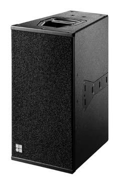
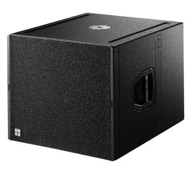


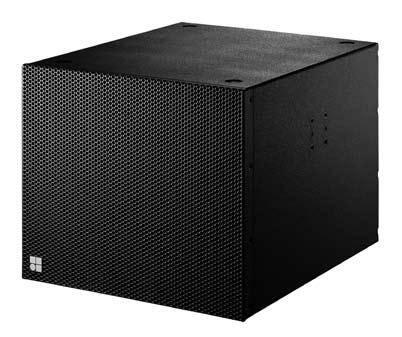
5 The Q-Series loudspeaker Q7, 0 loudspeaker Q subwoofer loudspeaker Qi7, 0 loudspeaker Qi, QiCSA subwoofer D6 amplifier amplifier d&b Q-Series 5
6 The and loudspeakers and loudspeakers The and are line array loudspeakers for use in vertical columns. The is the installation version of the loudspeaker, it differs only in cabinet construction and mounting hardware. The and cabinets are passive 2-way designs that houses 2 x 10 LF drivers and a 1.3 HF compression driver with a toroidal waveshaping device to achieve a 75 horizontal dispersion characteristic. The two 10 neodymium LF drivers are positioned in a dipolar arrangement providing an exceptional dispersion control even at lower frequencies, with the 75 nominal dispersion angle being maintained down to 400 Hz. and cabinets can be combined with the respective Q and Qi subwoofer systems: in mixed line array setups, as a separate subwoofer column or in ground stacked applications. For further extension of bandwidth and headroom ground stacked J-INFRA subwoofers can be used. The and cabinets are constructed from marine plywood and have an impact resistant paint finish. The front of the loudspeaker cabinets are covered with a replaceable acoustically transparent foam and protected by a rigid metal grill. Four M10 threaded inserts on each side panel of the cabinet enclosure are provided for attaching installation hardware whilst the cabinet incorporates a pair of handles and has integrated line array rigging hardware. System data Frequency response ( 5 db standard) Hz - 17 khz Frequency response ( 5 db CUT mode) Hz - 17 khz Max. sound pressure (1 m, free field) 1... with D db with db Input level (100 db SPL/1 m) dbu Loudspeaker data Nominal impedance...8 ohms Power handling capacity (RMS/peak 10 ms)...400/1600 W Nominal dispersion angle (h) Components...2 x 10 driver/1.3 compression driver...passive crossover network Connections...2 x EP5, optional 2 x NL4 Connections...2 x NL4 Pin assignments... EP5...1/2 NL4...1+/1 Weight /... 22/21 kg (49/46 lb) k 1k 4k 8k 16k and horizontal dispersion characteristics [22.83"] 580 [22.83"] 308 [12.13"] 410 [16.14"] 308 [12.13"] 410 [16.14"] [8.05"] cabinet dimensions in mm [inch] [8.05"] cabinet dimensions in mm [inch] k 1k 4k 8k 16k and vertical dispersion characteristics [12.20"] [6.06"] 60 [2.36"] 15 6 d&b Q-Series 1 Broadband measurement, pink noise, crest factor 4, peak measurement, linear weighting 2 Dispersion angle vs frequency plotted using lines of equal sound pressure (isobars) at 6 db and 12 db
7 The Q7 and Qi7 loudspeakers Q7 and Qi7 loudspeakers The Q7 and Qi7 are full range loudspeakers. The Qi7 is the installation version of the Q7 loudspeaker, it differs only in cabinet construction and mounting hardware. The Q7 and Qi7 are 75 x 40 passive 2-way cabinets housing 2 x 10 LF drivers and a 1.3 HF compression driver with a rotatable constant directivity horn and a passive crossover network. The two 10 neodymium LF drivers are positioned in a dipolar arrangement providing exceptional vertical dispersion control with the 40 nominal angle being maintained down to 400 Hz. The precisely controlled 75 horizontal dispersion performance provides the ideal pattern for many medium throw requirements. The horn can be rotated by 90. The Q7 and Qi7 can be used as stand-alone full range systems in combinations with other Q and Qi loudspeakers, ground stacked or mounted on a high stand. Q7 and Qi7 cabinets can also be combined in flown array systems. The Q7 and Qi7 cabinets are constructed from marine plywood and have an impact resistant paint finish. The front of the loudspeaker cabinets are covered with a replaceable acoustically transparent foam and protected by a rigid metal grill. Four M10 threaded inserts on each side panel of the Qi7 cabinet enclosure are provided for attaching installation hardware whilst the Q7 cabinet incorporates a pair of handles and has integrated line array rigging hardware. System data Frequency response ( 5 db standard) Hz - 17 khz Frequency response ( 5 db CUT mode) Hz - 17 khz Max. sound pressure (1 m, free field) 1... with D db with db Input level (100 db SPL/1 m) dbu k 1k 4k 8k 16k Q7 and Qi7 horizontal dispersion characteristics k 1k 4k 8k 16k Q7 and Qi7 horizontal dispersion characteristics/rotated horn [12.13"] [8.05"] [22.83"] 410 [16.14"] Q7 cabinet dimensions in mm [inch] k 1k 4k 8k 16k Q7 and Qi7 vertical dispersion characteristics k 1k 4k 8k 16k Q7 and Qi7 vertical dispersion characteristics/rotated horn 2 Loudspeaker data Nominal impedance...8 ohms Power handling capacity (RMS/peak 10 ms)...400/1600 W Nominal dispersion angle (h x v) x 40 Components...2 x 10 driver/1.3 compression driver...passive crossover network Connections Q7...2 x EP5, optional 2 x NL4 Connections Qi7...2 x NL4 Pin assignments... EP5...1/2 NL4...1+/1 Weight Q7/Qi /21 kg (49/46 lb) [8.05"] 580 [22.83"] 308 [12.13"] 410 [16.14"] [6.06"] 60 [2.36"] 310 [12.2"] Qi7 cabinet dimensions in mm [inch] 1 Broadband measurement, pink noise, crest factor 4, peak measurement, linear weighting 2 Dispersion angle vs frequency plotted using lines of equal sound pressure (isobars) at 6 db and 12 db d&b Q-Series 7
8 The 0 and 0 loudspeakers 0 and 0 loudspeakers The 0 and 0 are full range loudspeakers. The 0 is the installation version of the 0 loudspeaker, it differs only in cabinet construction and mounting hardware. The 0 and 0 are 110 x 40 passive 2-way cabinets housing 2 x 10 LF drivers and a 1.3 HF compression driver with a rotatable constant directivity horn and a passive crossover network. The two 10 neodymium LF drivers are positioned in a dipolar arrangement providing exceptional vertical dispersion control with the 40 nominal angle being maintained down to 400 Hz. 0 and 0 can be used as stand-alone full range systems, in combinations with other Q and Qi cabinets ground stacked or mounted on a high stand. The wide constant directivity performance provides remarkable transparency when used in close proximity to listeners. It is also ideally suited to ambient and distributed sound reinforcement tasks. When used in the upright configuration the 0 and 0 have a very accurate 110 horizontal constant directivity behaviour that is maintained down to approximately 800 Hz. The 0 and 0 cabinets are constructed from marine plywood and have an impact resistant paint finish. The front of the loudspeaker cabinets are covered with a replaceable acoustically transparent foam and protected by a rigid metal grill. Four M10 threaded inserts on each side panel of the 0 cabinet enclosure are provided for attaching installation hardware whilst the 0 cabinet incorporates a pair of handles and has integrated rigging hardware k 1k 4k 8k 16k 0 and 0 horizontal dispersion characteristics k 1k 4k 8k 16k 0 and 0 horizontal dispersion characteristics/ rotated horn [12.13"] [8.05"] 580 [22.83"] 410 [16.14"] k 1k 4k 8k 16k 0 and 0 vertical dispersion characteristics k 1k 4k 8k 16k 0 and 0 vertical dispersion characteristics/ rotated horn 2 System data Frequency response ( 5 db standard) Hz - 17 khz Frequency response ( 5 db CUT mode) Hz - 17 khz Max. sound pressure (1 m, free field) 1... with D db with db Input level (100 db SPL /1 m) dbu Loudspeaker data Nominal impedance...8 ohms Power handling capacity (RMS/peak 10 ms) /1600 W Nominal dispersion angle (h x v) x 40 Components... 2 x 10 driver/1.3 compression driver...passive crossover network Connections x EP5, optional 2 x NL4 Connections x NL4 Pin assignments... EP5...1/2 NL4...1+/1 Weight 0/ /21 kg (49/46 lb) 8 d&b Q-Series 15 0 cabinet dimensions in mm [inch] [8.05"] 580 [22.83"] 308 [12.13"] 410 [16.14"] [6.06"] 60 [2.36"] 310 [12.2"] 0 cabinet dimensions in mm [inch] 1 Broadband measurement, pink noise, crest factor 4, peak measurement, linear weighting 2 Dispersion angle vs frequency plotted using lines of equal sound pressure (isobars) at 6 db and 12 db
9 The Q, Qi and QiCSA subwoofers Q, Qi and QiCSA subwoofers Q, Qi and QiCSA-SUB are the dedicated subwoofers for the Q and Qi loudspeakers respectively and can be used to supplement the top cabinets in various combinations, either flown or ground stacked. The Qi and QiCSA are the installation versions of the Q subwoofer, they differ only in cabinet construction and mounting hardware. They are actively driven bass-reflex designs housing a long excursion 18" driver. The subwoofers can be combined with the respective Q and Qi loadspeakers in line arrays, as a separate column or in ground stacked applications where the subwoofers also mechanically support the top loudspeakers. The Q, Qi and QiCSA subwoofer cabinets are constructed from marine plywood and have an impact resistant paint finish. The front of the subwoofer cabinets are covered with a replaceable acoustically transparent foam and protected by a rigid metal grill. The QiCSA-SUB cabinet has foams fitted to both the front and rear sides of the cabinet, the grill facing backwards is fitted with a single NL4 connector (see page 15). Four M10 threaded inserts on each side panel of the Qi and QiCSA-SUB enclosure are provided for attaching installation hardware whilst the cabinet incorporates a pair of handles, an M20 threaded flange in the top panel and has integrated line array rigging hardware. 580 [22.83"] 493 [19.40"] cabinet dimensions in mm [inch] 668 [26.30"] 773 [30.42"] 377 [14.84"] 310 [12.20"] System data Frequency response ( 5 db standard)...40 Hz Hz Frequency response ( 5 db 100 Hz mode)...40 Hz Hz Max. sound pressure (1 m, free field) 1... with D db with db 580 [22.83"] 493 [19.40"] 668 [26.30"] 60 [2.36"] 124 [4.88"] Loudspeaker data Nominal impedance...8 ohms Power handling capacity (RMS/peak 10 ms)...400/1600 W Components...18 driver Connections...2 x EP5, optional 2 x NL4 Connections Qi/QiCSA-SUB...1 x NL4 Pin assignments... EP5...3/4, SenseDrive: 5 NL4...2+/2 Weight Q/Qi/QiCSA...42/37/40 kg (92.6/81/88 lb) Qi and QiCSA-SUB cabinet dimensions in mm [inch] 1 Broadband measurement, pink noise, crest factor 4, peak measurement, linear weighting d&b Q-Series 9
10 The rigging system Safety approval d&b loudspeakers and accessories are designed for set up and use within situations requiring compliance with the provisions and directives of BGV C1 Rule for the Prevention of Accidents. Z5154 Q Rigging set: Z5151 Q Splay link Z5152 Q Front link Z5153 Locking pins 8 mm Z5159 Q Flying frame WLL: 480 kg/1058 lb or twenty loudspeakers Z5160 Q Load adapter WLL: 480 kg/1058 lb or twenty loudspeakers; aiming of a column by 1/1, 1/2 or 1/4 detents Z5156 Q Flying adapter For three loudspeakers maximum Z5147 Rota clamp WLL: 500 kg/1100 lb; for a tube diameter up to 51 mm/2 Z5155 Q Hoist connector chain WLL: 480 kg/1058 lb or twenty loudspeakers E6507 1t Shackle Z5048 Flying pin 10 mm 10 d&b Q-Series
11 The rigging examples rigging examples With a 15 vertical HF dispersion per cabinet, the can be used to construct vertical columns that produce a curved coherent wave front. The mechanical and acoustical design of the cabinet enables vertical splay angles to be set between 0 and 14. cabinets can therefore be used in vertical configurations starting from two cabinets with a 15 to 30 dispersion, up to twenty cabinets with a fully user and venue defined vertical profile. For further information please refer to the "TI 385 d&b Line array design, ArrayCalc" and "Q-Series Rigging manual", which are available for download at line array with Z5159 Q Flying frame Z5154 Q Rigging set Z5155 Q Hoist connector chain E6507 1t Shackles / ground stack with Z5154 Q Rigging set ground stack with Z5159 Q Flying frame Z5154 Q Rigging set array with Z5156 Q Flying adapter Z5154 Q Rigging set Z5147 Rota clamp / array with Z5159 Q Flying frame Z5154 Q Rigging set Z5147 Rota clamp Z5160 Q Load adapter d&b Q-Series 11
12 The Q7/0 mounting accessories Safety approval d&b loudspeakers and accessories are designed for set up and use within situations requiring compliance with the provisions and directives of BGV C1 Rule for the Prevention of Accidents. Z5154 Q Rigging set: Z5151 Q Splay link Z5152 Q Front link Z5153 Locking pins 8 mm Z5161 Q Flying bracket Z5150 Q Swivel bracket Z5175 Qi Horizontal bracket Z5020 Flying adapter 02 Z5025 Flying adapter 03 Z5156 Q Flying adapter For three Q7 loudspeakers maximum Z5048 Flying pin 10 mm Z5015 TV spigot 02 Z5010 TV spigot with fixing plate Z5012 Pipe clamp for TV spigot WLL: 100 kg/220 lb; for a tube diameter up to 70 mm/2.75 Z5147 Rota clamp WLL: 500 kg/1100 lb; for a tube diameter up to 51 mm/2 Z5024 Loudspeaker stand adapter E6507 1t Shackle Q9032 M10 Safety eyebolt 12 d&b Q-Series
13 The Q7/0 mounting examples Q7/0 with Z5161 Q Flying bracket Z5010 TV spigot with fixing plate Z5012 Pipe clamp for TV spigot Q7/0 with Z5161 Q Flying bracket Z5024 Loudspeaker stand adapter Q7/0 with Z5150 Q Swivel bracket Z5010 TV spigot with fixing plate Z5012 Pipe clamp for TV spigot Q7/0 with Z5175 Qi Horizontal bracket Z5010 TV spigot with fixing plate Z5012 Pipe clamp for TV spigot Q7/0 with Z5020 Flying adapter 02 Z5015 TV spigot 02 Q7/0 with Z5156 Q Flying adapter Z5147 Rota clamp Q7/0 with Z5048 Flying pins 10 mm Q7/0 and with Z5161 Q Flying bracket Z5013 Loudspeaker stand winder M20 d&b Q-Series 13
14 The Qi rigging system Safety approval d&b loudspeakers and accessories are designed for set up and use within situations requiring compliance with the provisions and directives of BGV C1 Rule for the Prevention of Accidents. Z5145 Ci/Qi Mounting frame WLL: 240 kg/530 lb e.g. nine Q loudspeakers Z5170 Qi Mounting adapter Z5171 Qi Mounting plate Z5172 Mounting plate Z5147 Rota clamp WLL: 500 kg/1100 lb; for a tube diameter up to 51 mm/2 Z5160 Q Load adapter WLL: 480 kg/1058 lb or 20 loudspeakers; aiming of a column by 1/1, 1/2 or 1/4 detents 14 d&b Q-Series
15 The rigging examples rigging examples With a 15 vertical HF dispersion per cabinet, the can be used to construct vertical columns that produce a curved coherent wave front. The mechanical and acoustical design of the cabinet enables vertical splay angles to be set between 0 and 14. cabinets can therefore be used in vertical configurations starting from two cabinets with a 15 to 30 dispersion, up to nine cabinets with a fully user and venue defined vertical profile. Qi subwoofers can be integrated at any position within the array. Three subwoofers can be mounted together in CSA mode, where the centre QiCSA-SUB radiates to the back. For further information please refer to the "TI 385 d&b Line array design, ArrayCalc", which is available for download at /QiCSA-SUB Cardioid Subwoofer Array front view /QiCSA-SUB Cardioid Subwoofer Array back view Z5170 Z5172 Z5171 Flown / array with Z5145 Ci/Qi Mounting frame Z5160 Q Load adapter Z5147 Rota clamp / array with Z5145 Ci/Qi Mounting frame Z5170 Qi Mounting adapter Z5171 Qi Mounting plate Z5172 Mounting plate d&b Q-Series 15
16 The Qi rigging system The Qi7/0 rigging examples Safety approval d&b loudspeakers and accessories are designed for set up and use within situations requiring compliance with the provisions and directives of BGV C1 Rule for the Prevention of Accidents. Z5145 Ci/Qi Mounting frame WLL: 240 kg/530 lb Z5170 Qi Mounting adapter Z5171 Qi Mounting plate Z5172 Mounting plate Z5147 Rota clamp WLL: 500 kg/1100 lb; for a tube diameter up to 51 mm/2 Z5160 Q Load adapter WLL: 480 kg/1058 lb; aiming of a column by 1/1, 1/2 or 1/4 detents Z5170 Z5171 Flown Qi7/0 array with Z5145 Ci/Qi Mounting frame Z5160 Q Load adapter Z5147 Rota clamp Z5170 Qi Mounting adapter Z5171 Qi Mounting plate 16 d&b Q-Series
17 The Qi7/0 mounting and rigging accessories and examples Safety approval d&b loudspeakers and accessories are designed for set up and use within situations requiring compliance with the provisions and directives of BGV C1 Rule for the Prevention of Accidents. Z5161 Q Flying bracket Z5175 Qi Horizontal bracket Z5020 Flying adapter 02 Z5025 Flying adapter 03 Z5054 Ci60/Ci90 Flying adapter Z5044 MAX Bracket connector Z5053 Ci60/Ci90 Bracket connector Z5015 TV spigot 02 Z5010 TV spigot with fixing plate Z5012 Pipe clamp for TV spigot WLL: 100 kg/220 lb; for a tube diameter up to 70 mm/2.75 Z5024 Loudspeaker stand adapter Qi7/0 with Z5161 Q Flying bracket Z5010 TV spigot with fixing plate Z5012 Pipe clamp for TV spigot Qi7/0 with Z5175 Qi Horizontal bracket Z5010 TV spigot with fixing plate Z5012 Pipe clamp for TV spigot Qi7/0 horizontal array with Z5175 Qi Horizontal bracket Z5044 MAX Bracket connector Qi7/0 vertical array with Z5054 Ci60/Ci90 Flying adapter d&b Q-Series 17
 and Mac OS X 2 (10.4.10 or higher) operating systems.")

18 The d&b ArrayCalc calculator For both acoustic and safety reasons d&b line arrays must be designed using the d&b ArrayCalc simulation tool. It is available as a native stand-alone application for both Microsoft Windows 1 (XP or higher) and Mac OS X 2 ( or higher) operating systems. ArrayCalc is the system engineer's comprehensive toolbox for all tasks regarding acoustic design, performance prediction, alignment, rigging and safety parameters of the d&b line array systems and subwoofer arrays. In combination with the d&b Remote network, this can significantly reduce setup and tuning time in mobile applications, and allows for precise initial simulations in the planning of installations. EASE and DXF data export capabilities make for easy data transfer. The program allows the user to define up to five three-dimensional listening planes to quickly create a representation of the audience areas in a given venue, including balconies, side stalls and in-the-round scenarios. Special functions assist in obtaining the proper dimensions with laser distance finders and inclinometers. Additionally, up to two acoustic obstacles representing for example video cubes, which will obstruct the sound propagation, can be added to the model. Up to fourteen flown arrays or subwoofer columns can be defined in a project file as single hangs or in pairs, as well as a ground stacked subwoofer array consisting of up to twenty five stacks. They can be freely positioned according to their intended application, for example as main hang, outfill, delay line etc. Position, orientation, coverage and aiming are displayed in top and side views. For every array, achievable RMS level over distance is calculated with high resolution in real time, for either band-limited or broadband input signals. The comprehensive simulation precisely models the actual performance of the system, taking into account input level, all system configuration options (such as CUT, CPL, HFC or INFRA), limiter activity and air absorption. Acoustic shadowing, whether by obstacles (if defined) or a balcony overhang is also calculated. The load status of all rigging components is also constantly monitored and displayed to determine whether a given array is within the load tolerance. Subwoofer array design is assisted by coverage and polar plot prediction. A specialized algorithm allows the user to specify subwoofer positions and a coverage angle, which is then converted into appropriate delay times that result in the desired dispersion. The program allows the simulation of different arrays to be delayed to one another as well as showing arrival times and SPL Room Settings Arrays Sub Array 18 d&b Q-Series


19 The d&b ArrayCalc calculator at a freely definable reference point on one of the audience areas. For alignment of the flown system with the ground stacked bass array, the phase response of both the bass array and a selectable flown array is calculated at a definable reference point. Both simulations reflect changes in delay time to the single arrays in real time, greatly obviating the need for time consuming acoustic measurements to that end. The level distribution resulting from the interaction of all active arrays can be mapped onto the previously defined audience areas in a three-dimensional view which can also be zoomed, rotated and exported as a graphics file. Up to four diffferent configurations and their mappings can be temporarily stored for comparison. A comprehensive rigging plot with all necessary coordinates, dimensions and weights is automatically generated for export and printing, as well as a parts list detailing all the loudspeakers and rigging components required. Further information and useful guidelines are provided in the "TI 385 d&b Line array design, ArrayCalc", which is available for download at Alignment 3D Plot Rigging Plot 1 Microsoft Windows is a registered trademark or trademark of Microsoft Corporation in the United States and/or other countries 2 Mac OS is a trademark of Apple Inc., registered in the U.S. and other countries d&b Q-Series 19
20 VOLTAGE SEE LABEL ~ 50/60 Hz, 1000 W The D6 and amplifiers The D6 and are dual channel amplifiers developed and manufactured by d&b utilizing Digital Signal Processing (DSP) to incorporate loudspeaker specific configuration information and functions. These are designed for use with d&b loudspeakers, have both digital and analog signal inputs as well as link outputs, remote control and monitoring capabilities and switch mode power supplies. The level control incorporates a digital rotary encoder enabling selection of all operating modes in conjunction with a Liquid Crystal Display (LCD). Loudspeaker specific configurations for current d&b loudspeakers and a linear mode are contained within them, the exception being that the D6 does not include 2-Way Active and B2-SUB configurations. The digital elements of the D6 and are specified and constructed to achieve the best possible audio performance while maintaining a very low latency of 0.3 msec. The Digital Signal Processing is used to provide the loudspeaker specific configurations, sophisticated protection circuits modelling thermal and mechanical driver behaviour, and switch functions. User definable equalization and delay functions are incorporated in each channel of the amplifiers and can be used for applications such as front fills or under balcony delays without the need for external processors. The signal delay capability allows delay settings of up to 340 msec. (= 100 m/328 ft) to be applied independently to each channel as can the 4-band parametric equalizer, providing optional Boost/Cut or Notch filtering. A signal generator offering pink noise or sine wave program is also incorporated for test and alignment purposes. Every unit can be given a unique Device Name to simplify identification and a password protected LOCK function is also incorporated to prevent unauthorized changes. The D6 and amplifiers also detect incoming Pilot signals at its input (Input monitoring) and can use Load monitoring and System check functions to determine the status of the loudspeaker impedance. d&b System check is designed to verify that the system performs within a predefined condition and can be used to report the system condition after a show. d&b Load monitoring, on the other hand, enables automatic and continuous impedance monitoring and along with Input monitoring is designed for incorporation within applications specified to the requirements stated in the International Standard IEC Sound Systems for Emergency Purposes. Both can determine the status of an LF or HF driver in systems with multiple elements, even if these are crossed over passively. The D6 utilizes a switch mode power supply with PFC suitable for mains supply voltages 100 V/115 V/200 V/230 V, Hz whilst the utilizes an autosensing switch mode power supply for mains voltages 115/230 V, Hz (optional 100/200 V). Both power supplies have overvoltage protection and each amplifier has a temperature and signal controlled fan to cool the internal assemblies. The 2 RU lightweight D6 is specifically designed to deliver medium power into low impedance loads between 4 and 16 ohms. The 3 RU is specifically designed to produce high power into low impedance loads, typically those between 4 and 16 ohms. Due to differences in impedance response against frequency, the maximum number of cabinets driven by each channel varies depending on the loudspeaker type. Apart from selectable output configurations for dual channel, Mix TOP/SUB and 2-Way Active mode, the also provides d&b SenseDrive for use with the LF drivers in d&b active loudspeakers and subwoofers. Both amplifiers house an I/O panel containing: analog signal inputs with link outputs for each channel, an AES/EBU digital input with a link output and NL4 loudspeaker outputs. The I/O panel additionally offers the options of EP5 or NL8 loudspeaker outputs. The two RJ 45 REMOTE sockets at the rear of the D6 and the amplifiers integrate them into the d&b Remote network via CAN-Bus, enabling remote control and/or monitoring. A USB-B (D6) or a SUB-D9 () SERVICE interface is provided to enable future firmware updates containing new loudspeaker configurations or additional functions to be loaded to the units. D6 MAINS SUPPLY CH A DIGITAL AES/EBU ANALOG OUT A OUT B REMOTE SERVICE CH B D6 rear view rear view 20 d&b Q-Series
21 The D6 and amplifier data D6 Display ISP, GR, OVL A/B...LED indicators Liquid Crystal Display (LCD)...Graphic display/120 x 32 Pixel D6 Controls POWER, MUTE/LEVEL...Switch, rotary encoder Function switches...loudspeaker specific circuits 4-band equalizer...optional PEQ/Notch Delay setting msec. with 0.1 msec. detents Configurations...Current d&b loudspeakers and linear mode...except 2-Way Active and B2-SUB Frequency generator...pink noise or Sine wave D6 Connectors INPUT/LINK ANALOG A/B...3 pin XLR female/male 1 INPUT/LINK DIGITAL AES/EBU...3 pin XLR female/male 1 Sampling rate...48 khz /96 khz OUT CHANNEL A/B...NL4 REMOTE...2 x RJ 45 parallel SERVICE...USB Type B D6 Protection circuits Mains inrush current limiter A RMS at 230 V Loudspeaker switch on delay...approx. 2 sec. Overvoltage protection...up to 400 VAC D6 Data (linear setting with subsonic filter) Rated output power (THD+N < 0.1%) x 350 W into 8 ohms, both channels are driven...2 x 600 W into 4 ohms, both channels are driven S/N ratio (unweighted, RMS)...>110 dbr D6 Digital Signal Processing Sampling rate...96 khz/27 Bit ADC/24 Bit DAC Basic delay/latency analog input msec. D6 Power supply Switch mode power supply for /115/200/230v, Hz Mains connector...powercon 2 D6 Remote network Remote network...can-bus D6 Dimensions, weight Height x width x depth...2 RU x 19 x 353 mm/13.9 Weight...8 kg/17.6 lb Display ISP, GR, OVL A/B...LED indicators Liquid Crystal Display (LCD)...Graphic display/120 x 32 Pixel Controls POWER, MUTE/LEVEL...Switch, rotary encoder Function switches...loudspeaker specific circuits 4-band equalizer...optional PEQ/Notch Delay setting msec. with 0.1 msec. detents Configurations...Current d&b loudspeakers and linear mode Frequency generator...pink noise or Sine wave Connectors INPUT/LINK ANALOG A/B...3 pin XLR female/male 1 INPUT/LINK DIGITAL AES/EBU...3 pin XLR female/male 1 Sampling rate...48 khz /96 khz OUT CHANNEL A/B...Optional EP5/NL4/NL8 REMOTE...2 x RJ 45 parallel SERVICE...SUB-D9 female Protection circuits Mains inrush current limiter...5 A RMS at 230 V Loudspeaker switch on delay...approx. 2 sec. Overvoltage protection...up to 400 VAC Data (linear setting with subsonic filter) Rated output power (THD+N < 0.1%) x 750 W into 8 ohms, both channels are driven...2 x 1200 W into 4 ohms, both channels are driven S/N ratio (unweighted, RMS)...>110 dbr Digital Signal Processing Sampling rate...96 khz/27 Bit ADC/24 Bit DAC Basic delay/latency analog input msec. Power supply Autosensing switch mode power supply for /230 V, Hz...optional 100/200 V, Hz Mains connector...powercon 2 Remote network Remote network...can-bus Dimensions, weight Height x width x depth...3 RU x 19 x 353 mm/13.9 Weight...13 kg/29 lb 1 XLR pin assignment analog, inputs and links: 1 = GND, 2 = pos. signal, 3 = neg. signal XLR pin assignment digital, input and link: 1 = GND, 2 = signal, 3 = signal 2 PowerCon is a registered trademark of the Neutrik AG, Liechtenstein d&b Q-Series 21
22 The operation with D6 and amplifiers Operation with D6 and Max. LS per channel Q7 Qi7 0 0 QiCSA -SUB Max. LS per channel in special applications 1 Maximum loudspeakers per D6 or channel D6 and controller settings Q7 Qi7 0 0 CUT x x x HFC HFA x x CPL x x x x QiCSA -SUB 100 Hz x x CSA D6 and controller settings for each loudspeaker CUT mode Set to CUT, the cabinet low frequency level is reduced and is configured for use with d&b active subwoofers. HFC mode Selecting the HFC (High Frequency Compensation) mode compensates for loss of high frequency energy due to absorption in air when loudspeakers are used to cover far field listening positions. HFC should be used selectively, only for those cabinets covering distances larger than 50 m (160 ft). This enables the correct sound balance between close and remote audience areas, whilst all amplifiers driving the array can be fed with the same signal. HFA mode In HFA mode (High Frequency Attenuation), the HF response of the system is rolled off. The HFA provides a natural, balanced x frequency response when a unit is placed close to listeners in near field or delay use. High Frequency Attenuation begins gradually at 1 khz, dropping by approximately 3 db at 10 khz. This roll off mimics the decline in frequency response experienced when listening to a system from a distance in a typically reverberant room or auditorium. CPL function The CPL (Coupling) function compensates for coupling effects between closely coupled cabinets by reducing the low and mid frequency level. CPL begins gradually at 1 khz, with maximum attenuation below 400 Hz, providing a balanced frequency response when cabinets are used in arrays of two or more. The CPL function can be set in db attenuation values between 9 and 0, or a positive CPL value which creates an adjustable low frequency boost around 65 Hz (0 to +5 db). 100 Hz mode If the 100 Hz mode is selected, the upper operating frequency of the system is reduced to 100 Hz. This setting allows the subwoofer to supplement top cabinets in full range mode. CSA mode CSA (Cardioid Subwoofer Array) mode enables the combination of three or multiples of three subwoofer cabinets into an array that produces exceptional low frequency directivity control. The centre cabinet in a column is physically pointed to the rear and the CSA mode selected on the D6 or channel that powers this cabinet. The forward facing cabinets are driven with a D6 or channel set in the standard mode. The resulting cardioid behaviour of the array will significantly reduce the energy radiated to the rear. For further information please refer to the d&b TI 330 Cardioid Subwoofer Array, which is available for download at d&b SenseDrive The incorporates d&b SenseDrive for accurate control of LF drivers in d&b loudspeakers driven 2-Way Active or in d&b subwoofers driven actively, resulting in an extremely precise bass performance, even at high levels. SenseDrive is only available using a fitted with EP5 connectors and appropriate 5-wire cabling. For further information please refer to the d&b TI 340 SenseDrive, which is available for download at 22 d&b Q-Series 1 In applications with low continuous levels and low ambient temperatures
23 The Q-Series frequency responses k 10k 20k and standard and CUT (single cabinet) k 10k 20k Q7 and Qi7 standard and CUT k 10k 20k 0 and 0 standard and CUT k 10k 20k Q, Qi and QiCSA-SUB standard and 100 Hz k 10k 20k Correction of HFC k 10k 20k Correction of HFA d&b Q-Series 23
24 The Q-Series configuration examples A small Q-Series line array configuration as shown on the opposite page could consist of two amplifiers, three / loudspeakers, one Q7/Qi7 loudspeaker and four s/s. Three s/s are driven by one channel and one Q7/Qi7 from the other, this total load is acceptable for one. The Q7/Qi7 is suspended horizontally with a rotated horn as a downfill and enlarges the vertical coverage in the near field. Four s/s are driven by the second amplifier. 0 0 Laptop or PC running R1 A medium sized Q-Series configuration as shown on page 26 could consist of three amplifiers and six / loudspeakers along with two subwoofer stacks comprising three s/s and one QiCSA-SUBs in CSA mode. Two / loudspeakers are driven from one channel using three in total of the channels. The forward facing s/s are driven from two channels set in the standard configuration. The rear facing s/qicsa-subs are powered by the remaining channel configured for s with the CSA mode selected. In small or medium sized configurations using music program material a one to one ratio of / to s/s is recommended. Small basic configuration example R60 D6 CAN-Bus interface CAN-Bus A large sized Q-Series configuration as shown on page 27 could consist of eight amplifiers, sixteen / loudspeakers and two Q7/Qi7 loudspeakers along with two subwoofer stacks comprising twelve s or s with the two middle cabinets in CSA configuration and one J-INFRA. All the / loudspeakers are driven by eight channels, two Q7/Qi7 loudspeakers driven by one D6 amplifier are used to cover the near field. Eight forward facing s/s are driven by four channels set in the standard configuration, whilst the rear facing s/qicsa-subs are driven by two channels configured for s with the CSA mode selected. The frequency response below 40 Hz can be significantly enriched by the use of a J-INFRA subwoofer driven from one. As the horizontal constant directivity of a / column is maintained down to 400 Hz, two columns of s/s can be arrayed side by side to provide wider horizontal coverage. A horizontal angle of 50 between two columns provides the best compromise between level and frequency response. The two Q7s/Qi7s are used to cover the near field providing sufficient coverage and level. For further information please refer to the "TI 385 d&b Line array design, ArrayCalc", which is available for download at 24 d&b Q-Series
25 The Q-Series configuration examples Q7 Qi7 Laptop or PC running R1 R60 Small line array configuration example CAN-Bus CAN-Bus interface d&b Q-Series 25
26 The Q-Series configuration examples CAN-Bus CAN-Bus interface R60 Laptop or PC running R1 Small ground stacked configuration example QiCSA-SUB QiCSA-SUB Laptop or PC running R1 R60 CAN-Bus interface CAN-Bus Medium flown and ground stacked example 26 d&b Q-Series
27 The Q-Series configuration examples Laptop or PC running R1 R60 CAN-Bus interface CAN-Bus QiCSA-SUB QiCSA-SUB QiCSA-SUB QiCSA-SUB Q7 Qi7 Q7 Qi7 D6 J-INFRA Large flown and ground stacked configuration example d&b Q-Series 27
28 The Q-Series configuration examples Q7 Qi Laptop or PC running R1 0 0 R60 CAN-Bus interface CAN-Bus D6 QiCSA-SUB D6 QiCSA-SUB / flown line arrays in left/right configuration with Q7/Qi7 and 0/0 centre cluster, 0s/0s as fills and ground stacked Q/s and QiCSA-SUBs 28 d&b Q-Series
29 The Qi loudspeakers Weather Resistant and Special Colour options The Weather Resistant and Special Colour options are only available to order with the Qi version cabinets. Weather Resistant (WR) option The WR option enables operation of loudspeakers in changing ambient conditions, however it is not intended to enable permanent, unprotected operation of loudspeakers outdoors. Cabinets being used outdoors even with the WR option should always be aimed either horizontally or with a downward tilt. The QiCSA-SUB should only be aimed horizontally. An additional cover should be positioned over the loudspeakers. All cabinets are made of plywood to DIN68705 Part III. The wood is suitable for use outdoors after sealing and bonding. The wood is equivalent to flame spread class 3 and is designed for temperature ranges from 200 C to +100 C. All wood joints are bonded waterproof to stress class D4. All surfaces that are visible after removing the front grill are coated with two component PU paint (seaworthy, chemical resistant and temperature resistant to 110 C). Qi loudspeakers with the Weather Resistant option are supplied with a fixed cable. Cable type H-07-RN-F 2 x 2.5 mm 2 /AWG 13 with a length of 5.5 m (18 ft) as standard or length as required. Special Colour (SC) option The paint finish of all loudspeaker cabinets and most accessories can be executed in almost all RAL colours in accordance with the RAL colour table. Items such as chains, fixing screws, shackles, eyebolts and screws are not painted. Other paint finishes such as metallic are available on request. The acoustically transparent foam fitted behind the rigid metal grill is also painted with the requested RAL colour. d&b Q-Series 29
30 The D6 and amplifiers installation D6 and amplifiers installation The diagram opposite shows the thermal operating range within which the technical data will be maintained. The operation beyond this range is possible for a short time but for thermal reasons this may trigger the amplifier protection circuit for thermal overload. The D6 and amplifier enclosures are designed to fit a standard 19" equipment rack or cabinet. The front panel vent slot serves as a useful handle for lifting and moving amplifiers in and out of racks. When specifying a rack, be sure to allow extra depth (10 cm/4" is usually sufficient) to accommodate the cables and connectors at the rear of the amplifier(s). When mounting amplifiers into a 19" rack cabinet, provide additional support using shelves fixed to the inner sides of the cabinet or the mounting holes provided on the amplifier rear mounted rack ears; do not just rely on fixing and supporting amplifiers by their front panels. Since the amplifiers can generate a lot of heat, please ensure, whatever the mounting or racking arrangement, that adequate cool airflow is provided to avoid a build-up of hot air inside the rack leading to overheating. When setting up the amplifier, do not block or cover the rear panel air intake or the vents on the front panel of the amplifier. If amplifiers are installed in cabinets so that direct access to the rear panel filters is not possible, we recommend using additional fan modules with front mounted filters that can be easily replaced without opening the sealed cabinets. Max. average output Power [W] D Ambient Temp. in C Total average output power vs. ambient temperature D6 483 [19.00"] 443 [17.44"] 338 [13.31"] 483 [19.00"] 338 [13.31"] 443 [17.44"] 324 [12.56"] 348 [13.70"] 132 [5.2"] 5 [0.2"] 324 [12.56"] D6 enclosure dimensions in mm [inch] 88 [3.46"] 348 [13.70"] 3 [0.12"] Airflow enclosure dimensions in mm [inch] 30 d&b Q-Series
31 The D6 and amplifiers power consumption and power loss D6 and power consumption and power loss The power required from the mains supply and the waste heat produced by the amplifier power loss vary depending on the load impedance and the signal levels and characteristics (e.g. speech, music). In practice, the theoretical peak power consumption of a system will only be sustained for a short period of time. Basing mains current and air conditioning plant requirements on the peak power consumption of the sound system would result in a generously overspecified installation. The key factor in power consumption calculations is the crest factor of the music or speech signal - the ratio of peak to sustainable RMS voltage of the signal. The table below gives power figures for various types of signal waveforms. Mains supply Maximum number of devices per phase conductor when full output power is required: Mains supply Maximum number D6 230 V/16 A /100 V/15 A 2 1 In the USA and Japan we recommend the operation over two phase conductors (phase to phase 240 /200 V) or the use of mains leads with a much higher cross section. Signal waveform CF Duty Pout [W] Pin [W] Ploss [W] Iin [A] Uin [V] Sine wave 1.4 1/ Highly compressed 2.4 1/ music Music with low dynamic 4.0 1/ range D6 Power balance Signal waveform CF Duty Pout [W] Pin [W] Ploss [W] Iin [A] Uin [V] Sine wave 1.4 1/ Highly compressed 2.4 1/ music Music with low dynamic 4.0 1/ range Power balance Key: CF: Crest factor, Duty: Duty cycle, Pout [W]: Max. average output power (sum of both channels), Pin [W]: Input power (effective power) Ploss: Power loss (thermal power), Iin [A]: Resulting current, Uin [V]: Mains voltage 1 Maximum practicable operation 2 Only in conjunction with appropriate mains power supply installation d&b Q-Series 31
32 The d&b Remote network d&b Remote network The d&b Remote network enables central control and monitoring of a complete d&b loudspeaker system from anywhere in the network, be it from a PC in the control room, at the mix position, or on a wireless tablet PC in the auditorium. This central access to all functions, controls and detailed system information unlocks the full potential of the d&b system approach. Extensive monitoring and diagnostics enable detailed examination of the system performance. Control can be undertaken on individual loudspeakers, on multiple groups of loudspeakers or formed into groups that address the complete system. The flexibility and scalability of this approach, coupled with the inclusion of several types of interfaces, allow the d&b Remote network to be deployed to address the differing control and monitoring requirements in a broad variety of mobile and installed applications, regardless of their size. In mobile applications, system engineers may use the remote network to verify and tune the system. System check and device diagnostics enable detailed monitoring as and when required, before, during, or after a show. In installation projects system integrators can configure the remote network to offer access to different levels of control tailored to the operational demands. For example, simplified functionality for daily use and more complex functionality when multiple applications are required within one installation. Input and Load monitoring coupled with automatic error messages allow installation operators to ensure the optimum performance at all times. Terminating connector Daisy chain d&b Remote network Z6118 R60 USB to CAN interface D6 D6 D6 CAN-Bus CAN-Bus Interface Computer running R1 or R10 d&b Remote interfaces Every d&b amplifier is fitted with a Remote interface for the Controller Area Network (CAN) Bus. Each D6 and has two REMOTE connectors (RJ 45) to enable the CAN-Bus signal to be daisy chained through them. A simple d&b Remote network application consists of a computer running R1 Remote control software, an R60 USB to CAN interface, CAT 5 shielded twisted pair cable with shielded RJ 45 connectors and d&b D6 or amplifiers. Up to five R60 USB to CAN interfaces can be operated with one computer running R1, while a maximum of 504 amplifiers can be incorporated into one application. The maximum bus cable length of a d&b Remote network is 600 metres, see the adjoining table for cable length examples. The R70 Ethernet to CAN interface can be used for applications over longer distances, in conjunction with a fibre optic network for example. For further information about CAN-Bus cabling requirements and interfaces please refer to the d&b TI 312 d&b Remote network, which is available for download at Z6124 R70 Ethernet to CAN interface Cable cross section 0.25 mm 2 (24 AWG) 0.75 mm 2 (18 AWG) Examples of bus cable length Maximum bus cable length with numbers of amplifiers m (600 ft) 140 m (460 ft) 500 m (1650 ft) 330 m (1100 ft) 32 d&b Q-Series


33 The d&b Remote software R1 Remote control software R1 Remote control software is a graphical drag and drop user interface enabling the construction of a screen based virtual control surface for d&b systems, using the d&b Remote network. All major features, functions and controls available on the front panel of the D6 and amplifiers may be remotely controlled and/or monitored using R1. The architecture of R1 allows control of each channel of the amplifier as a single entity and enables the creation of groups of loudspeakers in as little, or as much detail as required by the user. When grouped together, a button or fader can control the overall system level, zone level, equalization and delay, power ON/OFF, MUTE and loudspeaker function switches such as CUT/HFA/HFC or CPL. R1 has extensive facilities for storing and recalling system settings allowing these to be repeated, as and when required. It is easy to adjust R1 project files for use with a different set of equipment at another location. Password protection is available to restrict access. R1 runs on PCs operating Microsoft Windows XP SP3/Vista SP1/7 1. A virtual machine enables R1 to run on the newer Intel 2 Mac 3 in parallel to the Mac OS 3 X, using the Windows driver for R60 USB to CAN interface. For older, Power PC based Mac computers, Windows emulation needs to be used, together with the R60 driver for Mac/PPC. For R70 Ethernet to CAN, no driver is needed. All the latest available drivers, R1 example files that can be used as templates and the TI 391 describing the effective use of R1 are available for download at R1 main page, groups and master controls R10 Service software R10 Service software enables the simultaneous firmware update of multiple amplifiers from a central location. Using R10, AmpPresets can be adjusted to the application requirements. R1 device page, individual devices, details view and group controls Integration with media control For integration of d&b audiotechnik loudspeaker systems into media control applications, the R70 Ethernet to CAN interface is used. Media control modules (drivers) are available at EN voice alarm applications For remote control of voice alarm applications Programmable Logic Controllers (PLCs) can be integrated into the d&b Remote network. 1 Microsoft and Windows XP/Vista/7 are either registered trademarks or trademarks of Microsoft Corporation in the United States and/or other countries 2 Intel is a trademark of the Intel Corporation in the United States and other countries 3 Mac and Mac OS are trademarks of Apple Inc., registered in the United States and other countries R1 equalizer page d&b Q-Series 33
The Q-Series Q-Series Q-SUB D12 Q1, Q7 Q10 d&b Remote network
 The Q-Series The Q-Series The Q-Series continues the established d&b audiotechnik approach to the design and manufacture of loudspeaker systems, adding another dimension to d&b s maxima. It is designed
The Q-Series Q-Series Q-SUB D12 Q1, Q7 Q10 d&b Remote network
 The Q-Series The Q-Series The Q-Series continues the established d&b audiotechnik approach to the design and manufacture of loudspeaker systems, adding another dimension to d&b s maxima. It is designed
C7-TOP Manual (3.0E)
") C7-TOP Manual (3.0E) References in the manual WARNING! CAUTION! IMPORTANT! This refers to a potentially dangerous situation which may lead to personal injury. This refers to a potentially dangerous situation
C7-TOP Manual (3.0E) References in the manual WARNING! CAUTION! IMPORTANT! This refers to a potentially dangerous situation which may lead to personal injury. This refers to a potentially dangerous situation
Symbols on the equipment. WARNING! Dangerous voltage!
 Q7 Manual (2.4 EN) Symbols on the equipment Please refer to the information in the operating manual. WARNING! Dangerous voltage! Contents Safety precautions...3 Information regarding use of loudspeakers...3
Symbols on the equipment. WARNING! Dangerous voltage!
 Q10 Manual (1.4 EN) Symbols on the equipment Please refer to the information in the operating manual. WARNING! Dangerous voltage! Contents Safety precautions...3 Information regarding use of loudspeakers...3
Symbols on the equipment. WARNING! Dangerous voltage!
 Qi1 Manual (1.3 EN) Symbols on the equipment Please refer to the information in the operating manual. WARNING! Dangerous voltage! Contents Safety precautions...3 Information regarding use of loudspeakers...3
C4-TOP Manual (3.0E)
") C4-TOP Manual (3.0E) References in the manual WARNING! CAUTION! IMPORTANT! This refers to a potentially dangerous situation which may lead to personal injury. This refers to a potentially dangerous situation
C4-TOP Manual (3.0E) References in the manual WARNING! CAUTION! IMPORTANT! This refers to a potentially dangerous situation which may lead to personal injury. This refers to a potentially dangerous situation
WARNING! CAUTION! IMPORTANT! References in the manual
 E3 Manual (3.0E) References in the manual WARNING! CAUTION! IMPORTANT! This refers to a potentially dangerous situation which may lead to personal injury. This refers to a potentially dangerous situation
Contents. The d&b System reality The xs-series The 8S loudspeaker The 10S and 10S-D loudspeakers...13
 xs xs-series Contents The d&b System reality... 4 The xs-series... 6 The 4S loudspeaker... The S loudspeaker...11 The 8S loudspeaker...12 The S and S-D loudspeakers...13 The 12S and 12S-D loudspeakers...14
Symbols on the equipment. WARNING! Dangerous voltage!
 Qi7 Manual (1.2 EN) Symbols on the equipment Please refer to the information in the operating manual. WARNING! Dangerous voltage! Contents Safety precautions...3 Information regarding use of loudspeakers...3
The J-Series d&b J-Series J-SUB J-INFRA D12 J12 d&b Remote network
 The J-Series The J-Series The d&b J-Series continues the established d&b audiotechnik approach to the design and manufacture of loudspeaker systems. It is intended for use in large-scale sound reinforcement
E1 controller module switches
 E1 Data Sheet Safety precautions Never stand in the immediate vicinity of loudspeakers driven at a high level. Professional loudspeaker systems are capable of causing a sound pressure level detrimental
Ci80 Manual (4.1 EN)
") Ci80 Manual (4.1 EN) Symbols on the equipment Please refer to the information in the operating manual. WARNING! Dangerous voltage! Contents Safety precautions...3 Information regarding use of loudspeakers...3
Ci80 Manual (4.1 EN) Symbols on the equipment Please refer to the information in the operating manual. WARNING! Dangerous voltage! Contents Safety precautions...3 Information regarding use of loudspeakers...3
Ti10 Manual (1.0 EN)
") Ti10 Manual (1.0 EN) Symbols on the equipment Please refer to the information in the operating manual. WARNING! Dangerous voltage! Contents Safety precautions...3 Information regarding use of loudspeakers...3
Ti10 Manual (1.0 EN) Symbols on the equipment Please refer to the information in the operating manual. WARNING! Dangerous voltage! Contents Safety precautions...3 Information regarding use of loudspeakers...3
Ci7-SUB Manual (2.1 EN)
") Ci7-SUB Manual (2.1 EN) Symbols on the equipment Please refer to the information in the operating manual. WARNING! Dangerous voltage! Contents Safety precautions...3 Information regarding use of loudspeakers...3
Ci7-SUB Manual (2.1 EN) Symbols on the equipment Please refer to the information in the operating manual. WARNING! Dangerous voltage! Contents Safety precautions...3 Information regarding use of loudspeakers...3
WARNING! CAUTION! IMPORTANT! References in the manual. This refers to a p otentially dangerous situation which may lead to personal injury.
 M2 Manual (5.0E) References in the manual WARNING! CAUTION! IMPORTANT! This refers to a p otentially dangerous situation which may lead to personal injury. This refers to a p otentially dangerous situation
MAX12 Manual (5.1 EN)
") MAX12 Manual (5.1 EN) Symbols on the equipment Please refer to the information in the operating manual. WARNING! Dangerous voltage! Contents Safety precautions...3 Information regarding use of loudspeakers...3
MAX12 Manual (5.1 EN) Symbols on the equipment Please refer to the information in the operating manual. WARNING! Dangerous voltage! Contents Safety precautions...3 Information regarding use of loudspeakers...3
Symbols on the equipment. WARNING! Dangerous voltage!
 E6 Manual (1.0 EN) Symbols on the equipment Please refer to the information in the operating manual. WARNING! Dangerous voltage! Contents Safety precautions...3 Information regarding use of loudspeakers...3
C4-TOP CAUTION! NL n.c. C4-TOP Data Sheet. Connector wiring. Speakon- NL4 and EP-5 pin assignments. Passive Crossover
 Data Sheet Safety precautions Never stand in the immediate vicinity of loudspeakers driven at a high level. Professional loudspeaker systems are capable of causing a sound pressure level detrimental to
General information Keep this document with the product or in a safe place so that it is available for future reference.
 xs 8S Manual 1.4 en General information 8S Manual Version: 1.4 en, 10/2018, D2608.EN.01 Copyright 2018 by d&b audiotechnik GmbH; all rights reserved. Keep this document with the product or in a safe place
E-Series. d&b E-Series
 E E-Series d&b E-Series Contents The d&b System reality... 4 The E-Series... 6 The E4 loudspeaker... The E5 loudspeaker... The E6 loudspeaker...2 The E8 loudspeaker...3 The E2 loudspeaker and E2-D loudspeaker...4
C6-MON CAUTION! EP NL n.c. C6-MON Data Sheet. Passive Crossover. Connector wiring. Speakon- NL4 and EP-5 pin assignments
 C6-MON Data Sheet Safety precautions Never stand in the immediate vicinity of loudspeakers driven at a high level. Professional loudspeaker systems are capable of causing a sound pressure level detrimental
V-Series. d&b V-Series 1
 V V-Series d&b V-Series Contents The d&b System reality... 4 The V-Series... 6 The V7P loudspeaker and Vi7P loudspeaker... The VP loudspeaker and ViP loudspeaker... The V-GSUB and Vi-GSUB...2 The V7P,
Q-SUB Manual (2.3 EN)
") Q-SUB Manual (2.3 EN) Symbols on the equipment Please refer to the information in the operating manual. WARNING! Dangerous voltage! Contents Safety precautions...3 Information regarding use of loudspeakers...3
Q-SUB Manual (2.3 EN) Symbols on the equipment Please refer to the information in the operating manual. WARNING! Dangerous voltage! Contents Safety precautions...3 Information regarding use of loudspeakers...3
Contents. d&b V-Series 3
 V V-Series Contents The d&b System reality.... 4 The V-Series.... 6 The V7P and Vi7P loudspeakers.... The VP and ViP loudspeakers....11 The V-GSUB and Vi-GSUB....12 The V7P, VP and V-GSUB transport accessories.....13
B2-SUB Manual (3.1 EN)
") B2-SUB Manual (3.1 EN) Symbols on the equipment Please refer to the information in the operating manual. WARNING! Dangerous voltage! Contents Safety precautions...3 Information regarding use of loudspeakers...3
B2-SUB Manual (3.1 EN) Symbols on the equipment Please refer to the information in the operating manual. WARNING! Dangerous voltage! Contents Safety precautions...3 Information regarding use of loudspeakers...3
Contents. The d&b System reality The Stage monitors The M2 monitor The M4 monitor The Stage monitor cases...
 M Monitors Contents The d&b System reality.... 4 The Stage monitors.... 6 The MAX2 monitor....1 The M6 monitor....11 The M4 monitor....12 The M2 monitor....13 The Stage monitor cases....14 The MAX2 mounting
Contents. The d&b System reality The E-Series The E8 loudspeaker The E12/E12-D loudspeakers The E15X subwoofer...
 E E-Series Contents The d&b System reality... 4 The E-Series... 6 The E4 loudspeaker... The E5 loudspeaker...11 The E6 loudspeaker...12 The E8 loudspeaker...13 The E12/E12-D loudspeakers...14 The E12X
The J-Series d&b J-Series J-SUB D12 J12 J-Series
 The J-Series The J-Series The d&b J-Series continues the established d&b audiotechnik approach to the design and manufacture of loudspeaker systems. It is intended for use in large-scale sound reinforcement
D Amplifiers Software
 D Amplifiers Software Contents The d&b System reality... 4 The d&b workflow... 6 The d&b ArrayCalc simulation software... 8 The d&b Remote network...10 d&b Remote network topology...12 The D6, and amplifiers...14
C4-SUB Manual (3.0E)
") C4-SUB Manual (3.0E) References in the manual WARNING! CAUTION! IMPORTANT! This refers to a potentially dangerous situation which may lead to personal injury. This refers to a potentially dangerous situation
C4-SUB Manual (3.0E) References in the manual WARNING! CAUTION! IMPORTANT! This refers to a potentially dangerous situation which may lead to personal injury. This refers to a potentially dangerous situation
J-INFRA Manual (1.1 EN)
") J-INFRA Manual (1.1 EN) Symbols on the equipment Please refer to the information in the operating manual. WARNING! Dangerous voltage! Contents Safety precautions...3 Information regarding use of loudspeakers...3
J-INFRA Manual (1.1 EN) Symbols on the equipment Please refer to the information in the operating manual. WARNING! Dangerous voltage! Contents Safety precautions...3 Information regarding use of loudspeakers...3
The E-Series E-Series D12 E-PAC E-Series E12-SUB
 The E-Series The E-Series The E-Series loudspeaker range from d&b audiotechnik comprises the smallest cabinets within the product range and are systems that are predominantly used as single units or in
D Amplifiers Software
 D Amplifiers Software Contents The d&b workflow... 6 The d&b ArrayCalc simulation software... 8 The d&b Remote network...10 d&b Remote network topology...12 The D6,, D20 and amplifiers...14 The D6 amplifier...18
Contents. The d&b System reality The J-Series The J8 loudspeaker The J12 loudspeaker The J subwoofer...12
 J J-Series Contents The d&b System reality... 4 The J-Series... 6 The loudspeaker...10 The loudspeaker...11 The J subwoofer...12 The J-INFRA subwoofer...13 The J-Series rigging system...14 The J-Series
E15-BX CAUTION! IMPORTANT!
 E15-BX Data Sheet Safety precautions Never stand in the immediate vicinity of loudspeakers driven at a high level. Professional loudspeaker systems are capable of causing a sound pressure level detrimental
2 Data Sheet. 2/B1 rigging
 2 Data Sheet Safety precautions Never stand in the immediate vicinity of loudspeakers driven at a high level. Professional loudspeaker systems are capable of causing a sound pressure level detrimental
D Amplifiers Software
 D Amplifiers Software Contents The d&b workflow.... 6 The d&b ArrayCalc simulation.... 8 The d&b Remote network....10 d&b Remote network topology....12 The DS10 Audio network bridge....14 The d&b amplifiers....16
SOUND PROJECTS Jonkerweg PM Hilversum The Netherlands Phone +31 (0) Fax +31 (0)
 Fax +31 (0)") S O U N D P R O J E C T S PRODUCT INFORMATION SP3-60 SOUND PROJECTS Jonkerweg 17-19 1217 PM Hilversum The Netherlands Phone +31 (0)35 6213233 Fax +31 (0)35 6215455 SP3-60 The SOUND PROJECTS 3-60 is a full-range
S O U N D P R O J E C T S PRODUCT INFORMATION SP3-60 SOUND PROJECTS Jonkerweg 17-19 1217 PM Hilversum The Netherlands Phone +31 (0)35 6213233 Fax +31 (0)35 6215455 SP3-60 The SOUND PROJECTS 3-60 is a full-range
SOUND PROJECTS Jonkerweg PM Hilversum The Netherlands Phone +31 (0) Fax +31 (0)
 Fax +31 (0)") S O U N D P R O J E C T S PRODUCT INFORMATION S-SERIES LINE ARRAY SYSTEMS SOUND PROJECTS Jonkerweg 17-19 1217 PM Hilversum The Netherlands Phone +31 (0)35 6213233 Fax +31 (0)35 6215455 V1.2 16-4-2004 Product
S O U N D P R O J E C T S PRODUCT INFORMATION S-SERIES LINE ARRAY SYSTEMS SOUND PROJECTS Jonkerweg 17-19 1217 PM Hilversum The Netherlands Phone +31 (0)35 6213233 Fax +31 (0)35 6215455 V1.2 16-4-2004 Product
RIGS STACKS ROCKS ROLLS
 RIGS STACKS ROCKS ROLLS Page 1 www.clairbrothers.com One Clair Boulevard, Manheim, PA 17545 717.665.4000 Key Features The kit Series loudspeakers are full range, high output loudspeakers ideal for speech
SOUND PROJECTS Jonkerweg PM Hilversum The Netherlands Phone +31 (0) Fax +31 (0)
 Fax +31 (0)") S O U N D P R O J E C T S PRODUCT INFORMATION X-ACT SOUND PROJECTS Jonkerweg 17-19 1217 PM Hilversum The Netherlands Phone +31 (0)35 6213233 Fax +31 (0)35 6215455 X-ACT / SP15 SYSTEM SOUND PROJECTS X-act
S O U N D P R O J E C T S PRODUCT INFORMATION X-ACT SOUND PROJECTS Jonkerweg 17-19 1217 PM Hilversum The Netherlands Phone +31 (0)35 6213233 Fax +31 (0)35 6215455 X-ACT / SP15 SYSTEM SOUND PROJECTS X-act
VUE al-4 Subcompact Line Array System -4 Acoustic Element & V4 Systems Engine Specification Sheet A Whole New World Of Possibilities lim Da ina
 VUE al-4 Acoustic Element & Systems Engine A Whole New World Of Possibilities ry ina m a eli at Pr D The utilizes advanced technologies to extract unparalleled performance from an ultra-compact and highly
D AmplifiersSoftware
 D Amplifiers Software Contents The d&b System reality... 4 The d&b Workflow... 6 The d&b ArrayCalc simulation software... 8 The d&b NoizCalc immission modelling software...0 The d&b Remote network...2
APEX ARRAY APEX 28HA / APEX 18SA
 APEX ARRAY APEX 28HA / APEX 18SA 16 18 19 APEX 28HA / APEX 18SA are Active Speakers for professional use, they can be used in following electro- magnetic environment: residential, commercial and light
IBIZA ONE Series IBZA10
 IBIZA ONE Series IBIZA ONE Series is the ultimate reference for dance clubs environments. A combination of high-end audio, sound quality, stunning aesthetics, extreme sound pressure level and reliability.
Data sheet AT-35 active. Arc-Series Architectural Sound Design.
 Data sheet AT-35 active Arc-Series Architectural Sound Design. AT-35 active loudspeaker The Fohhn AT-35 active is equipped with the latest generation of 12 /1 neodymium speakers. AT-35 active is equipped
datasheet TFA-600HDP FLEX ARRAY SERIES ENGINEERING INFORMATION FEATURES APPLICATIONS Digitally self-powered Line array or virtual point source element
 FLEX ARRAY SERIES ENGINEERING INFORMATION datasheet Flex Array series is a high performance modular loudspeaker system designed for use in a variety of medium scale line array or virtual point source sound
ARRAY Series. MINIArray / LA208 / LA122 LA312 / SW118M / SW218V APPLICATIONS
 ARRAY Series LA122 The Tecnare Array Series is a fully integrated line of self-powered DSP controlled loudspeakers that merge the singular advantages of array technology, with the application of computer
D12 Amplifier Hardware manual (2.0E)
") D12 Amplifier Hardware manual (2.0E) References in the manual WARNING! CAUTION! IMPORTANT! Note: This refers to a potentially dangerous situation which may lead to personal injury. This refers to a potentially
D12 Amplifier Hardware manual (2.0E) References in the manual WARNING! CAUTION! IMPORTANT! Note: This refers to a potentially dangerous situation which may lead to personal injury. This refers to a potentially
Data sheet PT-9 WaveLine. Perform- Series. Line-Array Systems.
 Data sheet PT-9 WaveLine Perform- Series Line-Array Systems. PT-9 WaveLine The Fohhn WaveLine ist a very high powerful line array System. PT-9 module, twin-coaxial, fully horn-loaded, 2x 10 neodymium,
IBIZA ONE Series IBZA1561
 IBIZA ONE Series IBIZA ONE Series is the ultimate reference for dance clubs environments. A combination of high-end audio, sound quality, stunning aesthetics, extreme sound pressure level and reliability.
Compact Sound Reinforcement System
 www.nexo-sa.com Complete directivity control comes to compact power. With a unique user-rotatable horn that lets users quickly select between two preset directivity options, ID24 brings unparalleled flexibility
user manual 1.0 (EN)
") X8 user manual 1.0 (EN) Document reference: X8 user manual (EN) version 1.0 Distribution date: September 24, 2015 2015 L-ACOUSTICS. All rights reserved. No part of this publication may be reproduced or
X8 user manual 1.0 (EN) Document reference: X8 user manual (EN) version 1.0 Distribution date: September 24, 2015 2015 L-ACOUSTICS. All rights reserved. No part of this publication may be reproduced or
Data sheet AT-661w. Arc-Series. Architectural Sound Design.
 Data sheet AT-661w Arc-Series Architectural Sound Design. AT-661w loudspeaker VSM The Fohhn AT-661w is a fullrange outdoor system. The system is fully weatherproof, with a robust housing constructed from
CBT 100LA Constant Beamwidth Technology
 CBT LA Constant Beamwidth Technology Line Array Column Loudspeaker with Sixteen 5 mm (2 in) Drivers Key Features: Patent-pending Constant Beamwidth Technology provides constant directivity up to the highest
Compact Sound Reinforcement System
 NEXO S. A. Parc D Activité du Pré de la Dame Jeanne B.P.5 60128 PLAILLY France Tel: +33 (0)3 44 99 00 70 Fax: +33 (0)3 44 99 00 30 E-mail: info@nexo.fr Compact Sound Reinforcement System www.nexo-sa.com
SOUND PROJECTS Karperweg SN Almere The Netherlands Phone +31 (0) Fax +31 (0)
 Fax +31 (0)") S O U N D P R O J E C T S GENERAL INFO AND OPERATION MANUAL FOR SPX SERIES SOUND PROJECTS Karperweg 16 1317 SN Almere The Netherlands Phone +31 (0)36 53 94 570 Fax +31 (0)36 53 00 578 Contents LINE-ARRAY
S O U N D P R O J E C T S GENERAL INFO AND OPERATION MANUAL FOR SPX SERIES SOUND PROJECTS Karperweg 16 1317 SN Almere The Netherlands Phone +31 (0)36 53 94 570 Fax +31 (0)36 53 00 578 Contents LINE-ARRAY
Orbis MU 21. Digital Delegate Microphone Unit with Loudspeaker Order #
 Digital Delegate Microphone Unit with Loudspeaker Order # 725.706 Supplied without gooseneck microphone FEATURES Coated plastic housing with metal bottom plate Inserts made of optically hardened acrylic
TECHNICAL DATA SHEET. FreeSpace DS 100SE. Loudspeaker. Product Overview. Key Features. Product Information. Applications
 Product Overview The Bose FreeSpace DS 100SE loudspeaker is a high-performance, surface-mount loudspeaker designed for foreground music and speech reproduction in a wide range of commercial applications,
TECHNICAL DATA SHEET DS 16S/DS 16SE. FreeSpace. Loudspeakers. Product Overview. Key Features. Product Information. Applications
 Product Overview Bose FreeSpace DS 16S and FreeSpace DS 16SE loudspeakers are high-performance, surfacemount loudspeakers designed for background music and speech reproduction in a wide range of commercial
C200 PRECISION PASSIVE LOUDSPEAKER. FEATURES: 2-way portable Precision Passive loudspeaker system APPLICATIONS
 C200 Featuring legendary Mackie sound quality and durability, the lightweight C Series 2-way Precision Passive loudspeakers deliver optimum performance in portable PA, stage monitor and permanent installation
LSP 500 PRO. Wireless Integrated Professional Audio System FEATURES ARCHITECT S SPECIFICATION
 Wireless Integrated Professional Audio System FEATURES Complete wireless integrated PA system Wireless control for up to 20 LSP 500 PRO via ipad or Windows device Integrated Bluetooth audio streaming Integrated
XENO 8. User & Installation Manual.
 XENO 8 User & Installation Manual www.audac.eu 2 Introduction 8 Full range loudspeaker cabinet The XENO series is a loudspeaker range specifically designed for fixed audio installations in modern environments,
F O R U M S E R I E S
 R E V.1 F O R U M S E R I E S INSTRUCTION BOOKLET MODELS FORUM 8, 10, 12, 15, 8M, 15M & FORUM 12SUB & 15SUB F O R T H E C L O S E S T A P P R O A C H T O T H E O R I G I N A L S O U N D TABLE OF CONTENTS
Features. General Specifications. Surface Mount Speaker VXS5/VXS5W. Sophisticated sound and design for matching any application. Technical Data Sheet
 Features Sophisticated sound and design for matching any application. Series comprises two full-range models and two subwoofers available in either black or white. Features newly customized transducers
LA8 Amplified Controller
 LA8 Amplified Controller 5 6 7 8 LA8 Amplified Controller main feature identifications: 4 3 2 1 9 10 1 On/Off Switch 2 Anti-Dust Cover 3 Input selection + Menu keys 4 Output selection keys 5 LED clip and
EQUALIZER BACKGROUND. PRE-AMP Line Driver
 INTRODUCTION Congratulations on your purchase of your new pre amplifier-equalizer. Our sonic excellence is considered our most important objective. Your selection of this component tells us you desire
i-5 TM Full Range Vertical Array Loudspeaker
 i-5 TM Full Range Vertical Array Loudspeaker Designed for medium-to-large venues and outdoor applications, the i-5 is Clair s latest innovation in large format line array system technology. Built from
SL4210/SL4210-WH. Ultra-Compact, Surface-Mounted 10-Watt Loudspeaker
 Features High-performance, surface-mountable loudspeaker for foreground music, AV playback and distributed sound Exceptional sound quality with wide frequency bandwidth and uniform dispersion 10-Watt,
Data sheet AT-40. Arc-Series Architectural Sound Design.
 Data sheet AT-40 Arc-Series Architectural Sound Design. AT-40 loudspeaker The Fohhn AT-40 is an etremely powerful, high-capacity speaker system in a comparatively compact housing. It combines efficiency,
HPA4202 1/5. 2-Channel High Power Multi-Impedance Amplifier. General Description. Features. Applications. AtlasIED.com. HPA4202 Front.
 1/5 HPA4202 2-Channel High Power Multi-Impedance Amplifier Features 70.7V/100V and 2Ω, 4Ω, and 8Ω Output 100V 70.7V 8Ω 2 x 1200W 4Ω 2Ω 2 x 2500W 8Ω BRIDGED 1 x 3800W 4Ω BRIDGED 1 x 4800W Balanced Inputs
ESM Series User Guide
 ESM Series User Guide ESM26 ESM12 The future of sound. Made perfectly clear. At KV2 Audio our vision is to constantly develop technologies that eliminate distortion and loss of information providing a
VP SERIES Active compact line array system V2208P V1212P V1218P
 VP SERIES Active compact line array system V2208P V1212P V1218P We've got the power, we are active! SAE Audio has a great experience developing professional audio products for over 15 years. Being the
Data sheet AS-20 / ASP-20. Arc- Series. Architectural Sound Design.
 Data sheet AS-20 / ASP-20 Arc- Series Architectural Sound Design. AS- 20 / ASP-20 subwoofer system Fohhn AS-20 / ASP-20 Compact bass system, 400 W, 1 12, vented design. Description The Fohhn AS-20 is a
VSX 8.2BP. Stunning Performance
 ation Applications Compact band pass subwoofer for portable and installation applications 400 Watts continuous, 1,600 Watts peak power Twin 8" bass drivers for extended low frequency system response to
CMS 603ICT BM. Optimised for Installation
 Product Information Document Full range ceiling loudspeaker for installation applications 60 Watts continuous, 240 Watts peak power 6" ICT (Inductive Coupling Technology) point source driver for extended
KI-215-SMA-II DESIGNED AND MADE IN THE USA USING DOMESTIC AND IMPORTED COMPONENTS SPECIFICATIONS PRODUCT OVERVIEW FEATURES
 KI-215-SMA-II DESIGNED AND MADE IN THE USA USING DOMESTIC AND IMPORTED COMPONENTS In 1946, Paul W Klipsch, genius & maverick, hand-built his first loudspeaker in a tin shed with the intention of bringing
KI-362-SMA-II DESIGNED AND MADE IN THE USA USING DOMESTIC AND IMPORTED COMPONENTS SPECIFICATIONS PRODUCT OVERVIEW FEATURES APPLICATIONS
 KI-SMA-II DESIGNED AND MADE IN THE USA USING DOMESTIC AND IMPORTED COMPONENTS In 194, Paul W Klipsch, genius & maverick, hand-built his first loudspeaker in a tin shed with the intention of bringing live
DESIGNED & TUNED IN THE USA CATALOGUE 2018 ALTOPROFESSIONAL.COM
 DESIGNED & TUNED IN THE USA CATALOGUE 2018 TS3 S E R I E S The all-new Alto Professional TS3 Series of professional loudspeakers deliver solutions for every performance and installation challenge. With
Orbis MU 41. Digital Flush Mount Delegate Microphone Unit Order #
 Digital Flush Mount Delegate Microphone Unit Order # 725.722 Optional CA OL loudspeaker module, not included Table installation supplied without gooseneck microphone FEATURES High-quality flush mounting
CMS 403DCE. Adjustable Tilt Angle
 Full range ceiling loudspeaker for installation applications 40 Watts continuous, 160 Watts peak power Next generation 4" Dual Concentric point source driver featuring Omnimagnet technology Torus Ogive
DVS 8T # # Superb Point-Source Performance
 Product Information Document Full range surface-mount loudspeaker for indoor and outdoor installation applications 7 Watts continuous, 28 Watts peak power 8" mineral loaded polypropylene driver with nitrile
The Future of Sound. Made Perfectly Clear.
 ESM Series User Guide ESM26 ESM12 The Future of Sound. Made Perfectly Clear. At KV2 Audio our vision is to constantly develop technologies that eliminate distortion and loss of information providing a
SR-L09 SR-L05 OPERATING INSTRUCTIONS TABLE OF CONTENTS 1. SAFETY PRECAUTIONS GENERAL DESCRIPTION FEATURES CONNECTIONS...
 OPERATING INSTRUCTIONS Speaker system SR-L09 SR-L05 TABLE OF CONTENTS 1. SAFETY PRECAUTIONS... 2 2. GENERAL DESCRIPTION... 3 3. FEATURES... 3 4. DIMENSIONAL DiagramS... 4 5. Wiring DiagramS... 4 6. Input
CMS 503ICT BM. Optimised for Installation
 Product Information Document Full range ceiling loudspeaker for installation applications 50 Watts continuous, 200 Watts peak power 5" ICT (Inductive Coupling Technology) point source driver for extended
KI-362-SMA-II MADE IN AMERICA: HOPE, ARKANSAS SPECIFICATIONS PRODUCT OVERVIEW FEATURES APPLICATIONS TRAPEZOIDAL 15 3-WAY LOUDSPEAKER
 KI-SMA-II MADE IN AMERICA: HOPE, ARKANSAS In 194, Paul W Klipsch, genius & maverick, hand-built his first loudspeaker in a tin shed with the intention of bringing live music into his living room. Remember
The StudioLive 18sAI is the
 1,000 watt Class D amplifier Universal switch mode power supply with power-factor correction 24-bit floating point, 96 khz DSP Temperature and overvoltage protection Excursion Limiting Wireless and wired
TitanONE Smart Mainframe Power Amplifier
 1/7 TitanONE Smart Mainframe Power Amplifier T112 General Description The AtlasIED TitanONE T112 Smart Mainframe Power Amplifier provides the latest signal automation, processing and amplification technologies
System Requirements Passive, Bi-amped and Tri-amped Loudspeakers
 Models covered by this Quick Start Guide TCS-61, TCS-122, TCS-152, TCS-1561, TCS-B15A, TCS-B15B, TCS-B218 Thank you for choosing a TURBOSOUND loudspeaker product for your application. If you would like
Data sheet AT-09. Arc-Series Architectural Sound Design.
 Data sheet AT-09 Arc-Series Architectural Sound Design. AT-09 loudspeaker The well-designed Fohhn AT-09 is essential for all applications requiring maimum acoustic efficiency and etremely compact speaker
D12 Amplifier Software manual (5.2EN) (Firmware V2.x.x)
 (Firmware V2.x.x)") D12 Amplifier Software manual (5.2EN) (Firmware V2.x.x) General Information D12 Amplifier Software manual (Firmware V2.x.x) Version 5.2EN, 02/2008, D2013.E.05 Copyright 2008 by d&b audiotechnik AG; all
D12 Amplifier Software manual (5.2EN) (Firmware V2.x.x) General Information D12 Amplifier Software manual (Firmware V2.x.x) Version 5.2EN, 02/2008, D2013.E.05 Copyright 2008 by d&b audiotechnik AG; all
CMS 503ICT LP. Optimised for Installation
 Product Information Document ICT Driver for ation Applications Full range ceiling loudspeaker for installation applications 50 Watts continuous, 200 Watts peak power 5" ICT (Inductive Coupling Technology)
CMS 603ICT LS. Optimised for Installation
 Product Information Document Full range ceiling loudspeaker for installation applications 60 Watts continuous, 240 Watts peak power 6" ICT (Inductive Coupling Technology) point source driver for extended
Data sheet FC-9 DSP system controller. Amp Contoller-Series DSP-Amplifiers + DSP-Controller.
 Data sheet FC-9 DSP system controller Amp Contoller-Series DSP-Amplifiers + DSP-Controller. FC-9 DSP system controller The Fohhn FC-9 digital DSP system controller was especially designed for fixed installations
CS-1 Active Full Range Integrated Commercial Audiovisual System
 Active Full Range Integrated Commercial Audiovisual System User Manual SAFETY INSTRUCTIONS PLEASE READ THROUGH THIS MANUAL FIRST BEFORE OPERATING THE CS-1 SYSTEM. Thank you for purchasing this Beta3 product
AMT-12 AMT-15. Professional Loudspeakers. Installation and Use Manual
 AMT-12 AMT-15 Professional Loudspeakers Installation and Use Manual 2008 Bogen Communications, Inc. Specifications subject to change without notice. 54-2183-01C 0907 Table of Contents Introduction 2 Speaker
MONITOR MR5S/MR5SW. Compact Two-Way Speaker. Safety First! Quick-Start Guide
 The MR5S (Black) and MR5SW (White) are a compact two-way speaker system designed for constant-impedance systems. The 5" carbon fiber woofer, in combination with a 0.75" soft dome tweeter mounted on a 105
Manchester - England. HD-LEDA Datasheet
 HD-LEDA Datasheet LEDA is a 600 W, 45 Hz capable, folded horn subwoofer. Designed for large venues and outdoor events, Leda can be combined with HD-MH or TRS horn clusters allowing for flexible setups
MU12Ba. User Manual. MU Series Pro Loudspeaker System. 12" Active Subwoofer. UM- MU12Ba v er A
 12" Active Subwoofer MU Series Pro Loudspeaker System User Manual UM- - 20090801 v er A SAFETY INSTRUCTIONS PLEASE READ THIS MANUAL FIRST Thanks for buying products. Read this manual first as it will help