NCS-TT106 Temperature Transmitter
|
|
|
- Alban Reed
- 5 years ago
- Views:
Transcription

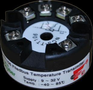
1 NCS-TT106 Temperature Transmitter
2 Contents 1. Brief Introduction Installation Dimension Installation Wiring FF Temperature TRANSMIITER Configuration Topology Connection Function Block Function Configuration PA Temperature TRANSMIITER Configuration Topology Connection Function Block Function Configuration Maintenance Technical Specification Basic Parameter RTD Parameter Thermocouple Parameter Physical Parameter... 34
3 1. Brief Introduction NCS-TT106 smart temperature module, using the fieldbus technology, is a new generation of smart fieldbus temperature transmitter and it is an indispensable field device for process control. NCS-TT106 transmitter integrates abundant function blocks and realizes not only general measurement function but also complicated control strategy. NCS-TT106 uses digital technology, so it can connect with many types of thermocouple and thermo resistive sensors. It has wide range and simple interface between field and control room, which reduces the expense of installation, operation and maintenance. NCS-TT106 supports HART, FF, and PA protocols. It can be widely used in the petroleum, chemicals, electricity, and metallurgical industries, etc
4 2. Installation 2.1 Dimension Φ Φ Φ Figure 2.1 Temperature Module Dimension (Unit: mm) 2.2 Installation Via positioning hole, use two screws to install the temperature module to temperature housing or rail
5 Figure 2.2 Installation 2.3 Wiring Connect Bus and Provide Bus Power Wire 3-Wire 4-Wire TC,mV RTD Ω RTD Ω RTD Ω + - Figure 2.3 Wiring Fieldbus temperature module power and bus signal share a pair of cable, and it is called bus cable. It is suggested the user use fieldbus special cable recommended by IEC
6 The signal cable and bus cable cannot share wires or wire slot with other device power wire, and they shall be away from device with high power. The shielded wires of bus ends shall be connected to the ground
7 3. FF Temperature TRANSMIITER Configuration 3.1 Topology Connection FF transmitter supports many kinds of connection, as shown in Figure 3.1. There is a transmitter bus connection, and the bus ends are connected with terminal matching resistance, which ensures the signal quality. The maximum length of bus is 1900m and it can be prolonged to 10km with repeaters. Control Master Fieldbus I/O FF bus Junction Box Point to Point Bus Tree Figure 3.1 FF Network Topology - 5 -
8 1900m Max FF Bus FF Bus Terminato Terminator Fieldbus Power Master FF device Figure 3.2 FF Bus Connection 3.2 Function Block FF smart transmitter realizes FF standard function blocks, shown as below. Please refer to related FF protocol documents for detailed info about function block setting. Function Block RESOURCE(RB2) TEMP_SENSOR 1(TTB) Description Resource block is used to describe device characters in the field, such as device name, manufacture, serial number. There is no input or output parameter in resource block. Generally there is only one resource block for each device. Transducer block is used to read sensor hardware data, or write the data in the field to related hardware. Transducer
9 AI 1(AI) block includes the info such as range, sensor type, linearization, I/O data, etc. Analog input function block is used to achieve transducer block input data and transfer it to other function blocks, and has the function of range conversion, square root, cut mantissa, etc. 3.3 Function Configuration Smart temperature transmitter supports FF Configuration Software, NCS4000 Configuration Software from Microcyber, NI-FBUS from NI, DeltaV from Rosemont, etc. Now take NI-FBUS from NI as an example to introduction the configuration method of smart temperature transmitter. Configuration Environment (1) PC, Windows 2000 or Windows XP; (2) NI USB-8486, H1 bus power, H1 terminator; (3) NI-FBUS Configurator. Sensor Type Configuration Sensor type can be set by modifying transducer block SENSOR_TYPE parameter, such as PT100, CU50, etc

10 Figure 3.3 Sensor Type Configuration 2-wire Zero Point Calibration Configuration For 2-wire measurement, 2-wire zero point calibration can be realized by modifying transducer block TWO_WIRES_COMPENSATION parameter. Firstly, give zero point value to channel to make a short circuit. Then set the TWO_WIRES_COMPENSATION parameter as Start to write in. If it is successful, read the parameter. If the parameter value is Finished, it means that 2-wire zero point calibration is successful. Enable Cold End Compensation If the sensor is thermocouple, the user can set cold end compensation via parameter RJ_TYPE, when it is set as Internal, it enable inside cold end compensation. At this - 8 -

11 time, RJ_TEMP value is the temperature value measured inside, that is SENCONDARY_VALUE. When it is set as External, the user can set EXTERNAL_RJ_VALUE to configure fixed cold end compensation value, the RJ_TEMP at this time is EXTERNAL_RJ_VALUE. When it is set as No reference, the cold end compensation is forbidden. Figure 3.4 RJ_TYPE Configuration 2-point Linearization Calibration Temperature transmitter has strict calibration in factory. Generally, it is not necessary for user to calibrate. The user can use CAL_POINT_HI, CAL_POINT_LO and CAL_UNIT to realize 2-point linearization calibration. The operation steps shown as following: - 9 -
12 (1) Make sure and set SESOR_TYPE, and set CAL_UNIT according to sensor type. Now it supports Celsius, Ohms and MV. (2) Set transducer block MODE parameter as OOS, and then set the SENSOR_CAL_METHOD as User Trim Standard Calibration. (3) Give standard data to channel to calibrate via standard source, when the input is stable, write calibration data to CAL_POINT_HI or CAL_POINT_LO according to upper limit calibration or lower limit calibration. It is successful if there is no write error. Notes: The calibration will be failed if there is a great deviation between write-in calibration data and practical input channel data
13 4. PA Temperature TRANSMIITER Configuration 4.1 Topology Connection Profibus PA transmitter supports many kinds of connection, as shown in Figure 4.1. There is a transmitter bus connection, and the bus ends are connected with terminal matching resistance, which ensures the signal quality. The maximum length of bus is 1900m and it can be prolonged to 10km with repeaters. PLC Master Parameterization Configuration Tool PROFIBUS DP 总线 Linker/Coulper PROFIBUS PA Bus Junction Point-to-point Bus with branch Tree Figure 4.1 PA Network Topology 11
14 1900m Max PA bus PA bus Terminator Terminator Fieldbus Power Linker/Coulper PA device Figure 4.2 FF Bus Connection 4.2 Function Block PA smart transmitter realizes PA standard function blocks, shown as below. Please refer to related PA protocol documents for detailed info about function block setting. Function Block Physical Block Transducer Block 12 Description Physical block describes device hardware information, recognizing and diagnosing information, including device tag number, software version, hardware version and installation dates, etc. Transducer block separates function blocks from the instrument input and output characteristic, and it mainly realizes the function such as calibration and linearization for input and output data, and then provides the processed
15 Analog Input Block data to AI via inner channel. AI block gets simulation processing value from the inner channel, and then processes the value, providing proper measurement value to master via bus communication. 4.3 Function Configuration PA smart transmitter parameter configuration follows Profibus PA Specification Version It can realize read and write function for transmitter function block parameters via Simatic PDM, also is able to configure temperature module via Siemens Step7. Configuration Environment (1) PC, Windows 2000 or Windows XP; (2) Siemens Step7 Configuration Software, Siemens PDM Device Management Software; (3) DP/PA coupler or linker; (4) 1 Master such as PLC, 2 Master such as CP5611; (5) PA Terminator; (6) Standard temperature source. Temperature Transducer Block Parameter Configuration Transducer block separates function block from sensors, actuators and other I/O devices. It depends on the device supplier to access and control I/O devices. Transducer block is able to get input data and set output data by accessing 13
16 I/O devices. Generally, transducer block has the function of linearization, specialization, temperature compensation and data s control and exchange, etc. Transducer block structure is shown as figure 4.3. Process Transducer Block Transducer Block AI FB( s) R.J. RJ_TEMP EXTERNAL_RJ_VALUE RJ_TYPE R.J. Comp. LIN Arithmetic Input Linearization BIAS_1 T1 Input 1 + LIN + SECONDARY_VALUE_1 PRIMARY_VALUE INPUT_RANGE, SENSOR_CONNECTION, COMP_WIRE1 LIN_TYPE, TAB_... Figure 4.3 Transducer Block Structure The transducer block parameters as following: Parameter Function Description Input fault: includes the failure diagnosed objects of all values. 0: Device normal Bit 0: Rj Failure INPUT_FAULT_GEN Bit 1: Hardware failure Bit 2-4: Reservation Bit 5: Manufacture designation Bit 6: Communication failure Bit 7: Manufacture designation 14
17 INPUT_FAULT_1 BIAS_1 INPUT_RANGE LIN_TYPE SENSOR_WIRE_CHECK_1 Input fault: the failure diagnosed objects related to SV_1 0: Input normal Bit 0: Higher than the upper range Bit 1: lower than the lower range Bit 2: Break Bit 3: Short Circuit Bit 4-7: Reservation Deviation value for processing parameters of Channel 1 Units are designated by PRIMARY_VALUE_UNIT. 0: mv Range 1 => mv : Ω Range 1 => Ohm : Ω Range 2 => Ohm 4000 Linearization type Enable open circuit testing and short circuit testing: 0: open circuit testing enable, short circuit testing enable; 1: open circuit testing enable, short circuit testing forbidden; 2: open circuit testing forbidden, short circuit testing enable; 3: open circuit testing forbidden, 15
18 PRIMARY_VALUE PRIMARY_VALUE_UNIT UPPER_SENSOR_LIMIT LOWER_SENSOR_LIMIT short circuit testing forbidden. Temperature module measurement value and status Units are designated by PRIMARY_VALUE_UNIT. Temperature module measurement value engineering unit code Sensor physical upper limit value Sensor physical lower limit value From Channel 1 and the calibrated value and status SECONDARY_VALUE_1 calibrated by BIAS_1. (SV_1) Units are designated by PRIMARY_VALUE_UNIT. Thermocouple additional parameters as following: Parameter Function Description Outer reference point temperature, can be input automatically. Units are designated by EXTERNAL_RJ_VALUE PRIMARY_VALUE_UNIT. If the unit is not for temperature, it should be set as. 16
19 Reference point temperature. Unit is set by RJ_TEMP PRIMARY_VALUE_UNIT. If the unit is not for temperature, it should be set as. Setting reference point type, coding as follows: 0: No reference, no compensation. 1: Inner, temperature at RJ_TYPE reference point self-tested by the device. 2: Outer, temperature at reference point from outer. Choose 1 when in default. Thermo resistance additional parameters as following: Parameter Function Description It can be used to connect sensor with 2-wire or 3-wire. SENSOR_CONNECTION 0: 2-wire 1: 3-wire 2: 4-wire Parameters defined by manufacture as following: Parameter Function Description SENSOR_VALUE_1 Original data value for sensor 1. CAL_POINT_HI Calibration value at the highest point; 17
20 CAL_POINT_LO CAL_MIN_SPAN CAL_UNIT The unit is designated by CAL_UNIT. Calibration value at the lowest point; The unit is designated by CAL_UNIT. Allowable minimum step length during the calibration ensures the calibration smoothly, and the distance between highest point and lowest point is not too close. The unit is designated by CAL_UNIT. Calibration units (, Ω, mv) TWO_WIRES_COMPEN 2-wire zero point compensation SATION Used to calibrate the sensor R0 ADJUST connected to temperature module PROFIBUS periodic data communication configuration PROFIBUS DP periodic data communication is to exchange input output data, between 1 master and slave station, in the polling way. The communication method is non-connected. In every cycling period, 1 master sends data exchange request, the slave answers it passively. The periodic data communication is mainly applied in 18

21 configuration between slave and PLC master. With it, master PLC receives slave input data or output the data to slave station. PA smart temperature module periodic data communication configuration is similar to PROFIBUS DP slave, only a coupler or a linker between PA bus and DP bus is needed to add between PA bus and DP bus. PA smart temperature module periodic data comes from output parameters of AI function block. There are 5 bytes, including 4 bytes of temperature floating data and 1 byte status byte. As for periodic communication, 2 identifiers are supported by transmitter, they are, short identifier 0x94 and long identifier 0x42, 0x84, 0x08 and 0x05. The user may use Siemens Step7 to configure periodic data communication for PROFIBUS PA. Following is an example for configuration via Siemens Step7: Turn on SIMATIC Manager, select PLC master and create a new project, shown as Figure 4.4. 双击进行硬件组态配置 Figure 4.4 Select PLC Master and Create a New Project 19

22 Click Hardware twice to turn on HW Config Software Hardware Configuration. Select Install GSD to install PA temperature module GSD file in Option list, shown as Figure 5.5. Figure 4.5 Install GSD After GSD file is installed successfully, the installed PA device will be listed in the PROFIBUS-PA index MicrocyberInc.on the right of HW Config Software. Click it and drag it to the PROFIBUS DP bus, shown as figure


23 GSD 文件安装后,PA 仪表显示在 P R O F I B S - PA 目录下 Figure 4.6 Drag PA Devcie to PROFIBUS DP Bus Download the configuration information to PLC master in the PLC list. Then the periodic data communication configuration between PA instrument and master is finished, shown as Figure 4.7. Figure 4.7 Download Configuration Info to PLC 21
24 PROFIBUS non-periodic data communication configuration PROFIBUS DP non-periodic data communication is the data communication between 2 master and slave, facing connection. The data communication is non-periodic, without affecting periodic data communication. The non-periodic data is mainly PA function block parameters, together with recognizing and diagnosing information for the device. The non-periodic data communication is mainly applied in management, recognizing, diagnosing, testing, maintaining for PA device. Siemens device management software SIMATIC PDM can be used to realize the non-periodic data configuration for PA instrument. There is an example given below to show non-periodic data configuration for PA instrument. Open the LifeList software attached by SIMATIC PDM, select Start to scan DP bus in Scan list, shown as Figure

25 Figure 4.8 Start LifeList After scanning the bus, slave device in DP bus will be listed, meanwhile the device manufacture ID number and some diagnosing information are displayed, shown as Figure 4.9. Figure 4.9 Scan DP Bus and List PA Device Click PA device twice to start SIMATIC PDM software. The user may read, write and diagnose parameter for PA device. Select the Device catalog... when the user is asked to select the PA instrument type, lead the GSD document. Microcyber Inc\NCS-TT106 can be selected for the NCS-TT106 series of PA temperature module, shown as Figure


26 Figure 4.10 Select Device Type After selecting the device type, click OK, thus non-periodic data communication is configured successfully. Via the function of upload and download function of PDM Software, the parameter read and write can be realized, shown as Figure Figure 4.11 Device Management via PDM Software 24
27 Configuration Function PA smart temperature module realizes PA standard function blocks. With PDM software, after configuration, choose Device -> Configuration, to do operation for transducer block or AI function block. Sensor Type Configuration Sensor Type can be set by modifying Characterization Type of transducer block and Input Range and Mode Parameters. E.g. PT100, CU50, etc. When Characterization Type Parameter is Linear, Input Range and Mode Parameter is effective. 2-wire Zero Point Calibration Configuration For 2-wire measurement, the user may use TWO_WIRES_COMPENSION parameter to do zero point calibration. First, give zero value to the channel, which will cut the channel off. Next, turn on PDM software, after the configuration, choose Device -> Configuration -> Transducer Block 1. In Advanced Settings, there is 2-wire calibration function. After pressing write button, when Finished is displayed, it means 2-wire zero point calibration is successful. Enable Cold-end Temperature Compensation When thermocouple is used as sensor, Reference Junction Temperature parameter of transducer block is cold-end temperature value. Primary Value is measurement value referenced cold-end temperature value. If 0 is to display 25
28 in primary value output, it can be realized by setting Reference Junction parameter. If 1 is to display in primary value output, it can be realized by measurement temperature as well as cold-end temperature as Primary Value output. The cold-end temperature compensation is enabled in default. 2-point Linearity Calibration The strict calibration must be done to temperature module in the factory, so it is not necessary for users to calibrate again. The parameters such as Lower Calibration Point, Upper Calibration Point and Calibration Unit are used to carry out 2-point linearity calibration. The operation steps are as following: (1) Turn on PDF software, after configuration; choose Device -> Calibration -> Lower/Upper, get page of temperature calibration. (2) Make sure of sensor type, set Characterization Type and Input Range and Mode, and set Calibration Unit according to sensor type. It supports the parameters, Ω, and mv. Write the parameter after the setting. (3) Give standard data to channel to calibrate via standard source. When the input is stable, write calibration data to Upper Calibration Point or Lower Calibration Point according to the operation one is upper calibration or lower calibration. If there is no write error, the calibration is successful. Notes: There should not be a 26
29 great deviation between written calibration data and practical input channel data, otherwise the calibration will be in failure. Notes: When the user uses Device -> Master Reset, it may bring in the instrument CPU reset as well as communication broken, which is normal. Please connect again. 27
30 5. Maintenance Phenomenon No Communication Solution Temperature Module Connection Check the bus cable connection Check bus power polarity Check bus cable shield, whether it is single point earthing or not Bus Power Bus power should in the range 9 ~ 32V for the temperature module, and bus noise and ripple should fulfill: (1) peak-to-peak value noise 16mV, 7~39kHz; (2) peak-to-peak value noise 2V, 47~63HZ, non-intrinsically safety (3) peak-to-peak value noise 0.2V, 47~63HZ, intrinsically safety (4) peak-to-peak value noise 1.6V, 3.9M~125MHZ. Network Connection Check network topology structure Check terminal matcher and wiring Check the length of main trunk and branch 28
31 Reading Error Address Conflict When coming to market, the temperature module has a random address, avoiding address conflict. But on a network segment it still possibly appears address conflicts. When conflict occurs, sometimes conflicting device will be temporary address online, you should just reset the device address. Sometimes device will not be temporary address online, you should cut off the electricity of conflicting device, and then power them one by one, modify the address of new powered device as non-conflicting. Temperature Module Failure Replace the temperature module with others for testing. Temperature Module Connection Failure Check sensor short circuit, open circuit, and earthing. Check sensor Noise Disturb Adjust damping Check the house earthing Check the terminal 29
32 Check the cable is away from the strong electromagnetic interference Software Configuration Check sensor type configuration Check function block parameter configuration Temperature Module Failure Replace the temperature module with others for testing. 30
33 6. Technical Specification Input Signal Channel RTD Wiring Bus Power Bus Signal Isolation 6.1 Basic Parameter Working Temperature -40 ~85 Humidity Range 10%~90%RH Start Time 5s Refresh Time 0.5s 31 / 36 Resistance: PT100, CU50, CU100, 0~500Ω, 0~4000Ω Thermocouple: B, E, J, N, K, R, S, T Voltage signal: -100mV~100mV Signal 2-wire, 3-wire, 4-wire 9~32 VDC Current consumption (static): 14mA Communication ratio 31.25Kbit/s, current mode Between terminal and housing: 500 Vrms (707 VDC)
34 EMC GB/T Protection IP RTD Parameter RTD Parameter at Normal Temperature (25 ) Signal Type Suggested Range ( ) Accuracy Resistance Signal 0~400Ω,0~4000Ω 0.09Ω, 0.7Ω PT ~850 ±0.3 PT ~850 ±0.3 CU50-50~150 ±0.5 CU100-50~150 ±0.4 RTD Other Parameter Wiring 2, 3, 4 Common Mode Rejection 70Db (50Hz and 60Hz) Series Mode Rejection 70dB(50Hz and 60Hz) Temperature Effect <50ppm/ 32 / 36
35 6.3 Thermocouple Parameter Thermocouple Parameter at Normal Temperature (25 ) Signal Type Suggested Range ( ) Accuracy mv -100Mv~100mV 0.05% B 500 ~1810 ±1.0 E -200 ~1000 ±0.4 J -190 ~1200 ±0.4 K -200 ~1372 ±0.4 N -190 ~1300 ±0.8 R 0 ~1768 ±1.0 S 0 ~1768 ±1.0 T -200 ~400 ±0.4 Thermocouple Other Parameter Compensation -2 ~5 Accuracy Sensor Type B,E,J,N,K,R,S,T -100mV~100mV Voltage Common Mode 70Db (50Hz and 60Hz) Rejection 33 / 36
36 Series Mode Rejection Temperature Effect 70dB(50Hz and 60Hz) <50ppm/ 6.4 Physical Parameter Dimension Housing Material 45*23mm Nylon 34 / 36
NCS-FI105 Fieldbus to Current Converter
 NCS-FI105 Fieldbus to Current Converter Contents Brief Introduction... 1 Installation... 2 Installation... 2 Wiring... 4 Principle and Structure... 6 NCS-FI105F Transmitter Configuration... 10 Network
OPERATION & MAINTENANCE INSTRUCTIONS MANUAL TT303 PROFIBUS PA TEMPERATURE TRANSMITTER APR / 15 TT303 VERSION 3 T T M E
 TT303 OPERATION & MAINTENANCE INSTRUCTIONS MANUAL PROFIBUS PA TEMPERATURE TRANSMITTER APR / 15 TT303 VERSION 3 T T 3 0 3 M E smar www.smar.com Specifications and information are subject to change without
SITRANS T. Temperature measuring instruments SITRANS TH400 FOUNDATION Fieldbus. Introduction. The Resource Block, Fieldbus Foundation
 Introduction 1 The Resource Block, Fieldbus Foundation 2 The Transducer Block 3 Analogue Input Blocks 4 PID Control Block, Fieldbus Foundation 5 SITRANS T Link Active Scheduler (LAS) 6 Temperature measuring
Configuration Manual STT17F. FOUNDA TION Fieldbus. STT3000 Smart Temperature Transmitter. Doc. No.: 34-ST Revision Date:
 Configuration Manual FOUNDA TION Fieldbus STT17F STT3000 Smart Temperature Transmitter Doc. No.: 34-ST-25-30 Revision Date: 2 CONTENTS Introduction............................................................
G0313 Modbus to FF Gateway User Manual
 G0313 Modbus to FF Gateway User Manual Microcyber Corporation Caution 1. Please don t take off/install gateway at random. 2. Please check if the power of gateway meets the power request in the User Manual.
Intech Micro 2300-RTD6 analogue input station MODBUS RTU slave application supplementary manual.
 Intech Micro 2300-RTD6 analogue input station MODBUS RTU slave application supplementary manual. MODBUS supplementary manual to the 2300-RTD6 Installation Guide. The 2300 series stations are designed to
Cube67 - Modular I/O station
 Compact modules Cube67 DI16 C 8xM12 Cube67 DI8 C 4xM12 Cube67 DI8 C 8xM8 Digital inputs Art.-No. UL 56602 UL 56612 UL 56622 approx. 50 ma approx. ma Terminator integrated Configuration PIN 2 input/diagnostic
G0307 Modbus to PA Gateway User Manual
 G0307 Modbus to PA Gateway User Manual Microcyber Corporation Caution 1. Please don t take off/install temperature board set at random. 2. Please check if the power of gateway meets the power request in
smar Specifications and information are subject to change without notice. Up-to-date address information is available on our website.
 smar www.smar.com Specifications and information are subject to change without notice. Up-to-date address information is available on our website. web: www.smar.com/contactus.asp Introduction INTRODUCTION
Temperature measurement board, optically isolated, 16/8/4 channels for thermocouples, Pt100, RTD, 18-bit
 Temperature measurement board, optically isolated, 16/8/ channels for thermocouples, Pt100, RTD, 18-bit APCI-3200 Up to 16 channels for thermocouples or 8 inputs for resistance temperature detectors (RTD)
Configuration Manual. FOUNDA TION Fieldbus SIGNALS THE BEST. Approvals. PROFIBUS PA / FOUNDA TION Fieldbus Transmitter
 Configuration Manual FOUNDA TION Fieldbus 5350 PROFIBUS PA / FOUNDA TION Fieldbus Transmitter No. 5350Q102(0420) From ser. no. 030640001 Approvals SIGNALS THE BEST 2 CONTENTS Introduction............................................................
ProfiPro Distributed PROFIBUS I/O Modules User Manual
 ProfiPro Distributed PROFIBUS I/O Modules User Manual 15/03/2012 V1.0 22/195 Prospect Highway Seven Hills 2147 NSW Australia Tel: +61 (02) 96248376 Fax: +61 (02) 96208709 Email: proconel@proconel.com Web:
SIMATIC. Distributed I/O Device ET 200iSP. Preface, Contents. Product Overview Getting Started with Commissioning. Configuration Options.
 SIMATIC Distributed I/O Device ET 200iSP Manual This documentation is available under order number 6ES7152-1AA00-8BA0 Preface, Contents Product Overview Getting Started with Commissioning Configuration
SEM310 SEM310X HART UNIVERSAL TEMPERATURE TRANSMITTER
 HART 5,6,7 COMPATABLE UNIVERSAL INPUT, DUAL CHANNEL ATEX & IEC Ex Version MATHS FUNCTIONS FLASH TESTED TO 4 KV DC INTRODUCTION The SEM310 is a HART 5 upwards, (generic device) compatible universal transmitter.
PROFIBUS DP/CAN Gateway PCA-100. User Manual
 PCA-100 REV 4.0 SiboTech Automation Co., Ltd. Technical Support: 021-5102 8348 E-mail: support@sibotech.net Catalog 1 Introduction... 2 1.1 About This Instruction... 2 1.2 Copyright... 2 1.3 Related Products...
DVPPF02-SL PROFIBUS DP Slave Communication Module
 DVPPF02-SL PROFIBUS DP Slave Communication Module Operation Manual DVP-0155320-01 Warning This operation manual provides introduction on the functions, specifications, installation, basic operation, settings
8 AI RTD Module NJ6020
 Product Description is a powerful and complete Programmable Logic Controller (PLC) Series with unique and innovative features. Due to its flexibility, smart design, enhanced capabilities and modular architecture,
HART UNIVERSAL TEMPERATURE TRANSMITTER
 SEM310 / SEM310X HART 5,6,7 COMPATABLE UNIVERSAL INPUT, DUAL CHANNEL ATEX & IEC Ex Version MATHS FUNCTIONS SENSOR CHARACTERISTICS DOWNLOAD VIA USB PORT ALLOWS FOR CUSTOM TYPES FLASH TESTED TO 4 KV DC INTRODUCTION
Intech Micro 2300-A8VI analogue input station MODBUS RTU slave application supplementary manual.
 Intech Micro 2300-A8VI analogue input station MODBUS RTU slave application supplementary manual. MODBUS supplementary manual to the 2300-A8VI Installation Guide. The 2300 series stations are designed to
Trident and Trident X2 Digital Process and Temperature Panel Meter
 Sign In New User ISO 9001:2008 Certified Quality System Home Products Online Tools Videos Downloads About Us Store Contact Policies Trident and Trident X2 Digital Process and Temperature Panel Meter Products
SAI Active Universal Pro
 Universal Pro - Overview Universal Pro Professional versions of the Remote I/O System featuring IP67 protection The modules in the Universal Pro systems provide additional I/O and functional modules for
H 250 with PROFIBUS-PA signal converter ESK3-PA
 KROHNE 12/2000 7.02117.21.00 GR Supplement to Installation and Operating Instructions Variable area flowmeter H 250 with PROFIBUS-PA signal converter ESK3-PA Version: 1.02/00-06-29 Suitable for software
JUMO ecotrans ph 03 Microprocessor transmitter/ switching device for ph/redox voltage and temperature
 Page 1/7 JUMO ecotrans 03 Microprocessor transmitter/ switching device for /Redox voltage and temperature with a 2-line LCD for mounting on a 35 mm DIN rail Brief description Depending on the configuration,
Safety Barriers. CEAG safety barriers can be used for all kinds of instrumentation applications.
 Safety Barriers Description Safety barriers limit the energy fed to an intrinsically safe circuit so that neither sparks nor thermal effects (hot surfaces) can cause an explosion. CEAG safety barriers
1/32-DIN TEMPERATURE CONTROLLER INSTALLATION, WIRING AND OPERATION MANUAL FORM 3882
 1/32-DIN TEMPERATURE CONTROLLER INSTALLATION, WIRING AND OPERATION MANUAL FORM 3882 This manual is intended for use in support of installation, commissioning and configuration of the 1/32-DIN Temperature
DINALOG A 144 x 36 A1400 Light-Strip Indicator
 DINALOG A x 6 A00 Light-Strip Indicator -9-0-0 /.00 Front panel dimensions: x 6 mm Light-strip indicator with 7 high-contrast LEDs Red LED display color Digital display range for portrait format: 999 to
General information. Engineering with. Supply voltage. Load voltage L+ Input current. Power losses. Memory. Work memory.
 Product data sheet SIMATIC S7-300, CPU 314C-2DP COMPACT CPU WITH MPI, 24 DI/16 DO, 4AI, 2AO, 1 PT100, 4 FAST COUNTERS (60 KHZ), INTEGRATED DP INTERFACE, INTEGRATED 24V DC POWER SUPPLY, 64 KBYTE WORKING
PROFIBUS and Integrated Safety architectures in Ex areas
 PROFIBUS and Integrated Safety architectures in Ex areas Since 1989, PROFIBUS has developed into a worldwide leading fieldbus system used in machine and process plant automation. The main reason why PROFIBUS
Thermocouple Input Module Product Specifications and Installation Data
 Thermocouple Input Module Product Specifications and Installation Data 1 DESCRIPTION The Horner APG Thermocouple Input Modules allow thermocouple temperature sensors to be directly connected to the PLC
HART UNIVERSAL TEMPERATURE TRANSMITTER
 SEM310 / SEM310X HART 5,6,7 COMPATABLE UNIVERSAL INPUT, DUAL CHANNEL ATEX & IEC Ex Version MATHS FUNCTIONS SENSOR CHARACTERISTICS DOWNLOAD VIA USB PORT ALLOWS FOR CUSTOM TYPES FLASH TESTED TO 4 KV A/C
RSTI-EP Slice I/O. Analog Input Modules `EP-3164, EP-3264, EP-3124, EP-3368, EP-3468 EP-3704, EP GFK-2960B November 2017
 November 2017 Module Status LED Channel Status LEDs Digital Input Connector Ground 24 V DC FE Analog Input Module RSTI-EP Slice I/O Analog Input Modules `EP-3164, EP-3264, EP-3124, EP-3368, EP-3468 EP-3704,
smart meters... 6 panel meters... 7 field displays... 8 display types loop powered displays TRANSMITTERS & CONVERTERS...
 2 content DISPLAYS... 4 smart meters... 6 panel meters... 7 field displays... 8 display types... 10 loop powered displays... 12 TRANSMITTERS & CONVERTERS... transmitters... 15 converters... 18 serial data
Driver TF(2)12(-EX)-PB
12(-EX)-PB") Supplementary Information Driver TF(2)12(-EX)-PB Content 1 Device - Revision Record / What is new?... 1 1.1 Hardware...1 1.2 Firmware...1 2 DTM - Engineer IT Device Type Manager... 1 2.1 Supported devices...1
Supplementary Information Driver TF(2)12(-EX)-PB Content 1 Device - Revision Record / What is new?... 1 1.1 Hardware...1 1.2 Firmware...1 2 DTM - Engineer IT Device Type Manager... 1 2.1 Supported devices...1
Transducers for Pt-100/1000, Resistors
 Transducers for Pt-100/1000, Resistors Microprocessor-based technology General Description Isolating transducers with digital programming of ranges, for DIN-rails or for printed circuit boards. Modules
NCS MIM. with MODBUS Interface. NET Concentrator System. September A. with MODBUS Interface
 September 2003 288-766-00 A NCS MIM with MODBUS Interface NCS MIM with MODBUS Interface Table of Contents The...3 About this Manual...3 The MODBUS Interface (MIM)... 4 Specifications MIM...5 Connecting
TRACKER 240 SERIES. Load Cell and Weighing Indicators. A Precision Measurement Instrument with Outstanding Features
 TRACKER 240 SERIES Load Cell and Weighing Indicators A Precision Measurement Instrument with Outstanding Features TRACKER 240 SERIES INDICATORS Ratiometric Measurement Tare and Auto Transducer Excitation
Intrinsically Safe Temperature Concentrator System
 Intrinsically Safe Temperature Concentrator System Up to 32 Channels per Network HART and PC configurable 2, 3 & 4-wire RTD or Thermocouple Transmitter like Sensor Diagnostics and performance, RTD ±0.1
Process modules Digital input PMI for 24 V DC inputs for 120 V AC inputs
 E031026 000823 Process modules Digital input PMI for inputs for 120 V AC inputs PMI Input E4, E5, GND L- PMI 120 V AC Input E4, E5, Common C E6, E7, GND L- E6, E7, Common C LEDs for the inputs operation
12-36 VDC/12-24 VAC Power Option 4-Digit Display, 0.56 (14.2 mm) or 1.20 (30.5 mm)
 or 1.20 (30.5 mm)") 4-20 ma & Relay Output Features 4-20 ma, ± 10 V, TC & RTD Inputs 12-36 VDC/12-24 VAC Power Option 4-Digit Display, 0.56 (14.2 mm) or 1.20 (30.5 mm) 24 VDC @ 200 ma Transmitter Power Supply Options Type
4-20 ma & Relay Output Features 4-20 ma, ± 10 V, TC & RTD Inputs 12-36 VDC/12-24 VAC Power Option 4-Digit Display, 0.56 (14.2 mm) or 1.20 (30.5 mm) 24 VDC @ 200 ma Transmitter Power Supply Options Type
Compact Multiprotocol I/O Module for Ethernet 4 Analog Inputs, Configurable as Voltage, Current, RTD or Thermocouple TBEN-S2-4AI
 EtherNet/IP, Modbus TCP, or PROFINET slave Integrated Ethernet switch 10 Mbps / 100 Mbps 2 x male M8, 4-pin, Ethernet-Fieldbus connection Glass fiber reinforced housing Shock and vibration tested Fully
Measuring transducers MI4x0 series Programmable transducers for RTD sensors MI450
 Measuring transducers MI4x0 series Programmable transducers for RTD sensors MI450 o Measuring of resistance of RTD sensors (Pt100, Pt1000, Ni100, Cu10,...) o Accuracy class up to: 0.5 o Programmable input
GE Fanuc IC694ALG221. Rx3i PacSystem
 GE Fanuc IC694ALG221 http://www.pdfsupply.com/automation/ge-fanuc/rx3i-pacsystem/ic694alg221 Rx3i PacSystem Input module, analog 4 point current. IC694A IC694AL IC694ALG 919-535-3180 sales@pdfsupply.com
Specifications
 Specifications 18200-40 Cole-Parmer Instrument Company 625 East Bunker Court Vernon Hills, Illinois 60061-1844 (847) 549-7600 (847) 247-2929 (Fax) 800-323-4340 www.coleparmer.com e-mail: techinfo@coleparmer.com
Basics of setting up. PROFIBUS-PA networks. Martin Ruck Siemens. Jason Nicholl Phoenix. Kris Hardaker United Utilities
 W05 Basics of setting up PROFIBUS-PA networks Martin Ruck Siemens Jason Nicholl Phoenix Kris Hardaker United Utilities Basics of setting up a Profibus PA Network Agenda 1. What is Profibus PA 2. Benefits
S900 Remote I/O System Intrinsic safety in the field ABB
 S900 Remote I/O System Intrinsic safety in the field ABB 2 S900 REMOTE I/O SYSTEM INTRINSIC SAFETY IN THE FIELD The S900 Remote I/O System 01 Example of Field housing FH660S in stainless steel with complete
Controller module. Brief description. Features. Block structure. Data Sheet Page 1/7
 M. K. Juchheim GmbH & Co UK USA Jumo Instrument Co. Ltd. Jumo Process Control Inc. 36035 Fulda, Germany Temple Bank, Riverway 735 Fox Chase Phone (0661) 6003-0 Harlow, Essex CM20 2TT Coatesville, PA 19320
PROFIsafe SITRANS. Pressure transmitter SITRANS P, DS III PROFIsafe series. Product Information 7MF4*34 04/2008 A5E
 1 SITRANS Pressure transmitter SITRANS P, DS III PROFIsafe series Product Information 7MF4*34 04/2008 A5E00732533-02 Safety Guidelines This manual contains notices you have to observe in order to ensure
S800 I/O ABB Automation
 S800 I/O 3BCNIIT F HW02-S800-V0102 Rev. 02/01 Page 1 S800 I/O S800 I/O 3 : Fieldbus Communication Interface (FCI) I/O Module Module Termination Unit (MTU), Compact or Extended version 3BCNIIT F HW02-S800-V0102
GFK-2415A March Type of sensor connection
 VersaMax IP Expansion Module has four analog differential inputs that can be configured as current or voltage inputs. It connects to a local bus that is interfaced to a Profibus-DP / PROFINET network by
EXOcompact Third Generation Manual
 EXOcompact Third Generation Manual DISCLAIMER The information in this manual has been carefully checked and is believed to be correct. AB Regin however, makes no warranties as regards the contents of this
HART Field Device Specification PR 5437 Device Revision 2
 HART Field Device Specification PR 5437 Version Revision: V4R0 Document Summary: This document explains the HART commands and features implemented in the PR 5437 transmitter, device revision 2. PR 5437
Catalog 1 Product Overview General Important User Information About the Gateway Function Features Tec
 PROFIBUS DP / Modbus TCP Gateway EP-321MP User Manual REV 1.2 Sibotech Automation Co., Ltd Technical Support: 021-5102 8348 E-mail:support@sibotech.net Catalog 1 Product Overview... 4 1.1 General...4 1.2
- SELF-TUNING PID ALGORITHM - INTUITIVE COLOR DISPLAY WITH TEXT MESSAGING - UNIVERSAL PROCESS AND TC/RTD INPUTS - MULTI- FUNCTION RAMP- DWELL/PROCESS
 ELK. ETK COMPACT BASIC CONTROL - SELF-TUNING PID ALGORITHM - INTUITIVE COLOR DISPLAY WITH TEXT MESSAGING - UNIVERSAL PROCESS AND TC/RTD INPUTS - MULTI- FUNCTION RAMP- DWELL/PROCESS TIMER - SOFT START OUTPUT
STA SIL 2 and SIL 3 Capable Programmable Current/Voltage and RTD/Thermocouple Safety Trip Alarms
 R February 2017 Description Part of the Moore Industries FS FUNCTIONAL SERIES, the exida SIL 2 and SIL 3 certified Safety Trip performs as a logic solver and acts on potentially hazardous process conditions;
Data sheet CC 03, Commander Compact (603-1CC21)
") Data sheet CC 03, Commander Compact (603-1CC21) Technical data Order. Type 603-1CC21 CC 03, Commander Compact General information Note - Features Display: 2 x 20 characters Interface: MP²I User memory:
Data sheet CC 03, Commander Compact (603-1CC21) Technical data Order. Type 603-1CC21 CC 03, Commander Compact General information Note - Features Display: 2 x 20 characters Interface: MP²I User memory:
Controller module. Brief description. Features. Block structure. Page 1/7. Data Sheet
 JUMO GmbH & Co. KG Delivery address:mackenrodtstraße 14, 36039 Fulda, Germany Postal address: 36035 Fulda, Germany Phone: +49 661 6003-0 Fax: +49 661 6003-607 E-mail: mail@jumo.net Internet: www.jumo.net
PROFIBUS Products. ICP Electronics Australia Pty Ltd Overview P 5-1
 5.1 Overview P 5-1 Selection Guide - - - - - - - - - - - - - - - - - - - - - - - - - - - - - - - - - - - - - - - - - - - - - - - - - - - - - P 5-2 5.2 Converters & Repeaters P 5-3 5.3 Gateways P 5-5 5.4
MODEL 9250 Preliminary data sheet
 Delivery: ex stock Warranty: 24 months Universal Instrumentation Amplifier for strain gage, potentiometric, DC/DC and incremental sensors MODEL 9250 Preliminary data sheet NEW burster TEDS Highlights Ultra-fast
RSTI-EP Slice I/O. Analog Input Modules `EP-3164, EP-3264, EP-3124, EP-3368, EP-3468 EP-3664, EP-3704, EP GFK-2960F September 2018
 September 2018 Module Status LED Channel Status LEDs Digital Input Connector Ground 24 V DC FE Analog Input Module RSTI-EP Slice I/O Analog Input Modules `EP-3164, EP-3264, EP-3124, EP-3368, EP-3468 EP-3664,
MTL830 SERIES. Cuts installation and cable costs for all IS hazardous-area circuits
 830 SERIES Cuts installation and cable costs for all IS hazardous-area circuits Reduce the cost of installing hazardous-area cabling Save installation time, space and weight Highlight problems quickly
ABB Instrumentation. Specification DataFile COMMANDER 100. the-easy-to use 1. /8 DIN controller with extensive application capabilities
 COMMANDER Universal Process Controller Specification DataFile PID controller with one shot autotune single loop, heat/cool and ramp/soak as standard Quick code, front face or PC configuration easy commissioning
Data sheet VIPA CPU 115DP (115-6BL22)
") Data sheet VIPA CPU 115DP (115-6BL22) Technical data Order no. Type 115-6BL22 VIPA CPU 115DP General information Note - Features Work memory [KB]: 16 Load memory [KB]: 24 Onboard 16x DI / 12x DO / 4x DIO
Data sheet VIPA CPU 115DP (115-6BL22) Technical data Order no. Type 115-6BL22 VIPA CPU 115DP General information Note - Features Work memory [KB]: 16 Load memory [KB]: 24 Onboard 16x DI / 12x DO / 4x DIO
PA ROUTERS. The following criteria can be applied when choosing the network transition:
 PA ROUTERS To create a smooth network transition between PROFIBUS DP and PROFIBUS PA, the SIMATIC product range offers two versions: the DP/PA coupler and the PA link. The following criteria can be applied
PC CONFIGURATOR Model: 27HUCFG. Users Manual , Minamitsumori, Nishinari-ku, Osaka JAPAN Tel: Fax:
 Model 27HU Universal Temperature Transmitter PC CONFIGURATOR Model: 27HUCFG Users Manual 5-2-55, Minamitsumori, Nishinari-ku, Osaka 557-0063 JAPAN Tel: +81-6-6659-8201 Fax: +81-6-6659-8510 http://www.m-system.co.jp/
PCD3.C90. Date Modification Asked by: Version E/A Bus Connector PCD2.K106 change to PCD3.K106 Müller.R 1.1
 Manual PCD3.C90 Revision History Date Modification Asked by: Version 14.09.09 E/A Bus Connector PCD2.K106 change to PCD3.K106 Müller.R 1.1 22.09.09 Added E/A Bus Connector PCD3.K116 Müller.R 1.2 06.01.10
Product Information on the Manual
 Product Information on the Manual Edition 04.2003 S7-300 Module Specifications, Edition 11/2002, (A5E00105505-02) Introduction The S7-300 product family has been enhanced and improved. This document contains
USB-2001-TC. USB-based Thermocouple Input. User's Guide
 USB-2001-TC USB-based Thermocouple Input User's Guide Document Revision 6A November 2014 Copyright 2014 Trademark and Copyright Information Measurement Computing Corporation, InstaCal, Universal Library,
Isolated Linearized RTD Input 5B34 FEATURES APPLICATIONS PRODUCT OVERVIEW FUNCTIONAL BLOCK DIAGRAM
 Isolated Linearized RTD Input 5B34 FEATURES Amplifies, Protects, Filters, and Isolates Analog Input. Linearize a wide variety of 2 & 3 wire RTDs. (True 4-wire RTD measurements are provided by the 5B35).
MICRO SERIES PROCESS DISPLAYS LARGE DIGIT MODELS
 The MICRO SERIES PROCESS DISPLAYS LARGE DIGIT MODELS Mighty-5 DPM MODELS Micro-P & Mighty-1 Mighty-1 Micro-P ELECTRO-NUMERICS, INC. Introduction The Electro-Numerics family of Digital Panel Meters and
BL compact multiprotocol fieldbus station for Industrial Ethernet 8 Analog Inputs for Thermocouple Elements BLCEN-8M12LT-4AI-TC-4AI-TC
 On-machine Compact fieldbus I/O block EtherNet/IP, Modbus TCP, or PROFINET slave Integrated Ethernet Switch 10 Mbps / 100 Mbps Two 4-pole M12, D-coded, connectors for fieldbus connection 2 rotary switches
Temperature Transmitter TF12, TF212
 Interface Description 40/11-51 EN Temperature Transmitter TF12, TF212 PROFIBUS PA, DPV1 Object dictionary / profile description P R O F I PROCESS FIELD BUS B U S Temperature Transmitter TF12, TF212 PROFIBUS
Distributed Control I/O System ADAM-8000 Series
 Distributed Control I/O System Series 16 Series Distributed Control I/O 16-2 Series Total Fieldbus Solution 16-4 CPU s ADAM8214-1BA01 PLC CPU214 16-6 ADAM8214-2BM01 PLC CPU214 with Profibus-DP Master 16-6
Configuration Manual FOUNDA TION Fieldbus and PROFIBUS PA
 Configuration Manual FOUNDA TION Fieldbus and PROFIBUS PA 6350 PROFIBUS PA / FOUNDA TION Fieldbus Transmitter No. 6350Q100(0407) From ser. no. 030145001 Approvals SIGNALS THE BEST 2 CONTENTS Introduction............................................................
8 Channel Analog Input Module Datasheet. Address / Baud rate / range configurable by the user
 8 Channel Analog Input Module Datasheet User s Manual Overview: DAM module is a new generation data acquisition and control system based on modular embedded systems. Adopting standard DIN35 rail mounting
INSTALLATION, OPERATION, CONFIGURATION AND MAINTENANCE MANUAL September/2016 VTT10-PH. HART TEMPERATURE TRANSMITTER panel model
 September/2016 VTT10-PH HART TEMPERATURE TRANSMITTER panel model COPYRIGHT All rights reserved, including translations, reprints, complete or partial reproduction of this manual, patent concession or model
itemp TMT180 Technical information
 Technical information itemp TMT180 Temperature head transmitter For resistance thermometers Pt100, settable using a PC, for installation in a sensor head Form B Application PC programmable (PCP) Temperature
SIMATIC PDM - The Process Device Manager
 SIMATIC - The Process Device Manager SIMATIC The Process Device Manager A&D AS PA PM (Ra) 01.04.03 1 SIMATIC - The Process Device Manager SIMATIC is the universal tool for commissioning, maintenance, diagnostics
The PROFIBUS and PROFINET Company. COMbricks Modules. Copyright 2013 PROCENTEC. All rights reserved.
 Modules SCOPE Repeater Module Name 1 Channel RS 485 SCOPE Repeater Type 1 Order code 101 201210 Description 1 Channel RS 485 PROFIBUS SCOPE repeater module with integrated quality oscilloscope for 12 Mbps
Programmable temperature transducer from Pt1000 sensor to current loop 4-20 ma Instruction Manual
 T4111 TRANSDUCER Programmable temperature transducer from Pt1000 sensor to current loop 4-20 ma Instruction Manual Instruction manual for use of T4111 transducer Transducer is designed for temperature
STT 3000 Series STT250 Smart Temperature Transmitters Specifications Models STT25H, STT25S, STT25M, STT25D EN0I-6031 March 2010
 STT 3000 Series STT250 Smart Temperature Transmitters Specifications Models STT25H, STT25S, STT25M, STT25D EN0I-6031 March 2010 Introduction Honeywell s STT 3000 family of microprocessor based smart temperature
Universal Serial/PROFIBUS DP Gateway GT200-DP-RS User Manual V6.1 SST Automation
 GT200-DP-RS V6.1 SST Automation E-mail: SUPPORT@SSTCOMM.COM WWW.SSTCOMM.COM Catalog 1 About the Gateway...4 1.1 Product Function...4 1.2 Product Features... 4 1.3 Technical Specifications... 4 1.4 Related
Temperature/Process Controllers Manual
 3200 SERIES Temperature/Process Controllers Manual The innovative range of 3200 controllers offer precision control of temperature and other process variables together with a host of advanced features
-Camille Bauer Div. of Absolute Process Instruments, Inc. Phone: Fax: J-1
 Solving Your Y Application Challenges! Phone: 800-462-4040 Fax: 800-949-7502 www.apicb.com 1220 American Way Libertyville, IL 60048 USA Copyright Absolute Process Instruments, Inc. 02/03 CBSK2003A J-1
C160 Wall-/Pipe Mounted Universal Process Indicator
 Data sheet DS/ EN Rev. I Wall-/Pipe Mounted Universal Process Indicator reliable process indicator, wherever it s needed High visibility LED display the clearest view of your process status 0.1% measurement
SIEMENS. SIMATIC Description of the optional components 3. FIELD ENGINEERING Catalog data 4 PACKAGE System Overview Part 2: Configuring and startup
 SIEMENS Foreword, Contents Part 1: Field Engineering Package Introduction 1 Components of the field engineering package 2 SIMATIC Description of the optional components 3 FIELD ENGINEERING Catalog data
ACT20X-(2)HTI-(2)SAO Temperature/mA converter. Safety Manual
HTI-(2)SAO Temperature/mA converter. Safety Manual") ACT20X-(2)HTI-(2)SAO Temperature/mA converter Safety Manual 1.1 Revision history Version Date Change 00 04/2014 First Edition 01 11/2017 Products added 1.2 Validity This manual is valid for the following
ACT20X-(2)HTI-(2)SAO Temperature/mA converter Safety Manual 1.1 Revision history Version Date Change 00 04/2014 First Edition 01 11/2017 Products added 1.2 Validity This manual is valid for the following
UNIVERSAL TEMPERATURE TRANSMITTER
 UNIVERSAL INPUT, DUAL CHANNEL ATEX & IEC Ex Version MATHS FUNCTIONS SENSOR CHARACTERISTICS DOWNLOAD VIA USB PORT ALLOWS FOR CUSTOM TYPES FLASH TESTED TO 4 KV DC INTRODUCTION The SEM210 is a universal transmitter
Data sheet CPU 115 (115-6BL02)
") Data sheet CPU 115 (115-6BL02) Technical data Order no. 115-6BL02 Type CPU 115 General information Note - Features 16 (20) inputs 16 (12) outputs from which are 2 PWM 50 khz outputs 16 kb work memory,
Data sheet CPU 115 (115-6BL02) Technical data Order no. 115-6BL02 Type CPU 115 General information Note - Features 16 (20) inputs 16 (12) outputs from which are 2 PWM 50 khz outputs 16 kb work memory,
For 2-wire Universal Temperature Transmitter B6U. PC CONFIGURATOR Model: B6UCFG. Users Manual
 For 2-wire Universal Temperature Transmitter B6U PC CONFIGURATOR Model: B6UCFG Users Manual 5-2-55, Minamitsumori, Nishinari-ku, Osaka 557-0063 JAPAN Tel: +81-6-6659-8201 Fax: +81-6-6659-8510 http://www.m-system.co.jp/
HRM-0800 Instruction Manual
 HRM-0800 Instruction Manual Table of Contents 1 Highway Addressable Remote Transducer (HART ) 4 2 General Specifications 5 3 Dimensions: 6 4 General Description 7 4.1 Introduction 7 4.2 Purpose 8 4.3 Functions
IE/PB LINK PN IO. PROFINET applications
 IE/PB LINK PN IO PROFINET applications Protection of investment due to simple connection of PROFIBUS DP slaves to PROFINET IO controller Enables the use also in plants with PROFIsafe applications Independence
Operation Instruction For Temperature Simulator
 Operation Instruction For Temperature Simulator INDEX 1. Safety Information..1 2. Instrument Panel Layout and Function 3 3. Replacing the Battery...4 4. Power-on/off of Simulator 5 5. Output from Simulator...5
Murdoch University Engineering Thesis. Appendix XII. Profibus PA System Configuration Instructions
 Appendix XII Profibus PA System Configuration Instructions Author: Hao Xu Page: p8 - p Last modified: // This is part of the Engineering Thesis WinCC SCADA System via Profibus & OPC by Hao Xu. 8 P a g
AMC 8 & IOC 8T. Analog Monitoring Card Type AMC 8 and Input / Output Card Type IOC 8T FEATURES
 Analog Monitoring Card Type AMC 8 and Input / Output Card Type IOC 8T FEATURES Two cards providing 8 channels of temperature and process monitoring for VM 600 systems 8 channels of software selectable
Cube20. Application-oriented. Installation-friendly. Efficient
 Cube20 Application-oriented Installation-friendly Efficient 02 Cube20 Universal and flexible combined with Cube67 03 CUBE20 FIELDBUS I/Os FOR CONTROL CABINETS Application: Control cabinets Plant construction
USER MANUAL MULTI COLOR TOUCH SCREEN PAPERLESS RECORDER MODEL : ARC2020
 USER MANUAL MULTI COLOR MODEL : ARC2020 ACCSYS ELECTRONICS 140/6B, GOLDEN INDUSTRIAL ESTATE, JAWAHARLAL NEHRU ROAD, GERUGAMBAKKAM, CHENNAI - 600122 Tel: 044 60505599 / 60505511 E-mail : sales@accsyselectronics.com
Commissioning Benefits
 Freedom to Choose. Power to Integrate. Commissioning Benefits Andreas Agostin MTL Instruments On behalf of Fieldbus Foundation Marketing Committee Freedom to Choose. Power to Integrate. Commissioning Benefits?
Model B3HU. PC CONFIGURATOR Model: B3HUCFG. Users Manual
 Model B3HU PC CONFIGURATOR Model: B3HUCFG Users Manual 5-2-55, Minamitsumori, Nishinari-ku, Osaka 557-0063 JAPAN Tel: +81-6-6659-8201 Fax: +81-6-6659-8510 http://www.m-system.co.jp/ E-mail: info@m-system.co.jp
Fisher FIELDVUE DVC6200p Digital Valve Controller Device Setup and Accessing Communication and Calibration using Siemens SIMATIC Manager/PDM
 Instruction Manual Supplement Fisher FIELDVUE DVC6200p Digital Valve Controller Device Setup and Accessing Communication and Calibration using Siemens SIMATIC Manager/PDM Contents Related Documents...
R1M-GH THERMOCOUPLE & DC INPUT MODULE MODEL. Remote I/O R1M Series. (16 points)
") Remote I/O R1M Series THERMOCOUPLE & DC INPUT MODULE (16 points) MODEL MODEL & SUFFIX CODE SELECTION R1MGH2T MODEL Modbus protocol I/O TYPE GH2 : Thermocouple or DC input, 16 points FIELD TERMINAL TYPE
Remote I/O R1M Series THERMOCOUPLE & DC INPUT MODULE (16 points) MODEL MODEL & SUFFIX CODE SELECTION R1MGH2T MODEL Modbus protocol I/O TYPE GH2 : Thermocouple or DC input, 16 points FIELD TERMINAL TYPE