Instruction It can display battery voltage, discharge current, time, battery
|
|
|
- Maximilian Chase
- 5 years ago
- Views:
Transcription
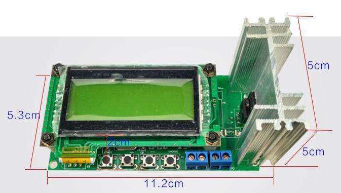
1 Feature: Instruction NC, constant current battery discharge instrument It can display battery voltage, discharge current, time, battery capacity, power, total power, resistance Auto remember the last set of discharge voltage and the discharge current Backlight can be used software controlled switch There are constant load resistance test function Specification: Supply voltage: 5V micro usb Supply current: About 70ma, off the backlight <1ma Battery discharge voltage: 0-15v, 1mv step The initial battery voltage: 0-15V Discharge current: 0.1A - 3A, Step 0.01A. But also effect by the 20W discharge power limit. Accuracy: Voltage does not exceed 10mv, current does not exceed 5ma. (Battery resistance uses of the DC method, so accuracy is not high.)

2 Battery cut-off voltage reference set: Select the type of battery Applicable battery nominal voltage Ni-Cd hydrogen V 1.0V Lithium phosphate V 2.5V Lithium battery V 3.0V Mobile power V 4.0V Lead-acid battery 12-14V 10.5V Termination voltage Ue Wiring: Micro usb connection power supply:

3 1. Four-wire connection: from the battery positive and negative, respectively, leads to two lines. Two lines lead out from the battery positive, connect A+ V+. Two lines lead out from the battery negative, connect V- A-. A+ A- should use thick line, the discharge current is passed through from here. V+ V- can uses thin line. Both sides of the board has marked. 2. Two-wire connection: On the main control board, short connect the V- A- and V+ A+. Two lines lead out from the battery holder (positive and negative), respectively connect to A+ A-.


4 Note: Measure battery internal resistance please use four-wire connection. Four-wire and two-wire connection looks the same, considering the wire resistance, then is not the same, discharge power has exceed 8W, it needs home cooling fan.
 1. Set the cut-off voltage, the discharge current.")

5 How to use? (PIC 1: Main control board) Micro usb female connect 5v power supply. The upper left corner pin serial port to be connected to 5v power supply. 5v power supply need only connect micro usb, one of serial port pin. (PIC 2: Boot interface) 1. Set the cut-off voltage, the discharge current. After start-up, enter PIC2 boot interface. Buzzer will beep when boot. The second line on the LCD display setting cut-off voltage, the discharge current, the first line shows the battery voltage current. Line 2 blinking, means that you can press + or - to adjust. Press the Select key to move the cursor. After setting up, press the Start button to enter the discharge mode. (PIC3 discharge main interface)

6 2. After entering the discharge mode, see pic 3 discharge screen. The first line shows the discharge voltage, discharge current, the discharge current may change constantly as instructions for performing current feedback, the range of change is less than the current 5ma. The second line shows the discharge time, the battery capacity. Battery capacity unit is ah, show only a special symbol, arranged vertically AH. Press the + key to make the first line of the display setting switch voltage and current, actual voltage current. When the actual voltage is displayed, the penultimate line of the first character is R. When the display setting voltage and current, the first line of the penultimate character is S. Press the "-" button to change the second line of the display. You can display the discharge capacity x.xxxah, x.xxx Ω within the resistance. Show resistance within three seconds after discharge. It can also display the power, total power, the unit is w, wh 3. Press the Start button to return to the main menu, the time capacity will be cleared. Press the Select key also return to the main menu, but time capacity is not cleared, the timer is not timely, time-keeping. Return to the main menu, the discharge current will becomes 0 4. Battery end of discharge, or the battery voltage is less than the setting cut-off voltage will stop the discharge. The first line of the reciprocal of a smiley face character display. Time counting is stopped, the battery capacity does not change. LCD backlight starts flashing. At this time you can press the plus or minus button to make the backlight always on. You can press the start key to return (time, capacity is cleared), press select to return (time capacity is not clear). 5. If the battery voltage is less than the setting cut-off voltage, press the start button will display Bat <vol set!!!, press the start button to return to the main menu. If the battery voltage is higher than 15v, displays vol high!!, press Start to return to the main menu. In this case it must be reduced or disconnecting the battery, otherwise, always show vol high!!

 8. bat res: Fig5 is a resistance measurement interface.")
7 (PIC4 Main menu) 6. Main Menu function selection: Boot screen long press the SELECT button to enter the main menu. Press the plus or minus key to select the function, select the function of the cursor blinks. Press the select button to enter the selected function. Press Start to return to the main menu between to enter the function. Main menu functions: 1. main menu 2. bat res 3. c source 4. load mah 5. bat choose 6. pat set Main menu screen showing the boot screen. (Figure 5 Resistance Measurement) 8. bat res: Fig5 is a resistance measurement interface. The first line of the far right of the display Z, this function can measure the internal resistance of the battery directly. Press the Select button to select the current size. Press Start to start measuring internal resistance. The first line shows the battery voltage and current. Measuring resistance except that a short pulse current to test resistance, accuracy is not high. It includes wiring resistance, contact resistance of the electrode. But the four-wire connection it is difficult to eliminate contact resistance.

 10.")
8 (Figure 6: a constant current source) 9. c source. The figure 6 is a constant current source function. The first line shows the current and voltage. The second line shows the current setting of the constant current source. Press the select key, plus or minus key to set the current size. The difference with battery capacity test is that in this function, even if take away the battery, it will not exit, re-access the battery, the current will reaches the specified current, if the discharge of the battery capacity is not enough, it will not exit this function mode (FIG7 battery capacity memory recovery) 10. load mah In the power and memory capacity of the unit discharge process, will memory the discharge capacity. Each additional 100mah, recorded once. Enter the main menu load mah, will display the Figure 7 interface. Press Select to load the last time discharge memory capacity, and the second line will show "Mah is". Last discharge capacity will displayes for 3 seconds. The best note of this parameter. From the beginning of this capacity accumulated discharge capacity. Press the start button without loading, discharge capacity from 0.


9 (Figure 8 backlight selection) 11. Par set Function selection: The machine parameters selection. (Figure 9 Fan start power selection) 12. The parameters of the first item is back light Referring to Figure 8. Press the plus or minus key to display the second line ON, OFF, AUTO. ON and AUTO means backlight is always open. Off means the backlight is always off. Press the select key to set the selected memory, press the start button does not remember the new settings. Then proceed to the next setup interface 13. wat of fan: fan control. Set W vaule, if the power is greater than this value, the fan starts. Press plus and minus keys to change the W vaule. Press Select key to save, press tart button not to save. Then enter into the next setting interface Note: If the discharge power exceeds 8W or current exceeds 2A, please replace a large radiator or add fans. 14. beep setting: buzzer switch ON, AUTO both means open. Off means turn off. Press the Start button to enter the next setting screen 15. temperature: For the test use only, press the start button to enter the next setting screen
.")
10 (Figure 10 current mode selection) 16. cur0.1? (Fig 10) The current machine has two modes: constant current discharge, the discharge current is reduced to 0.1x after constant. The second mode is after constant current discharge is completed, then reducing the discharge current is gradually reduced to 0.1x setting current (not less than 0.1a). Reach the cutoff voltage discharge until the end. This way is effectively to inferior battery, the battery can release more capacity. Selection Method: The interface of FIG. 12. Press plus or minus keys to move the cursor. If the cursor is in Y, means the selection 0.1x discharged, the battery icon becomes empty battery. If the cursor is in N, means the selection of constant current discharge, the battery icon becomes 3 grid power. Press the start button, do not save the settings, press the Select key to save the settings. FIG. 12

11 Calibration 1. Prepare a voltage adjustable power supply (0-15V). Calibration voltage and current needs a high precision multimeter, voltage stable adjustable voltage source. Disconnect the power discharge device, press the plus or minus key at the same time and does not let go, then power on, enter the calibration interface. Adjustable voltage source positive and negative connect to the battery terminals of the instrument. When calibration requires uses four-wire connection. (Figure 11 Voltage Calibration) 2. Step 1: Figure 11 voltage calibration interface: The adjustable voltage source to 0.924V, The first line shows the calibration voltage. Press the Select button to change the position of the cursor, press the plus or minus keys to change the value at the cursor position. So that the display actual voltage is consistency with adjustable voltage supply on the first row. The cursor on the first line to the right of the "Y" when press the start button is to save data, then enter the next process. Cursor is not "Y" when press the start button without saving the data and enter to the next step. 3. Step 2: 5v 1v calibration, adjustment is the same with the above. (Figure 12 current calibration, 0a and 0.05a)
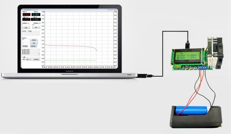
12 4. Step 3: Figure 12 current calibration interface: The positive voltage supply and discharge device in series between the A + ammeter. The first line left shows the current 0.000a. At this time disconnect a+ terminal connection, so that the tester has no current input cursor, when the cursor at Y, press the start button to save. When the cursor is not in Y, press the start button without saving a Calibration: Put a+ and the positive of an adjustable power supply connected together, and string into the multimeter current, when the cursor on the numbers in front of "P", uses plus or minus keys to change the value of P, can be changed the current size. Then move the cursor to in front of "a", so that the vaule in front of "a" is the same with and multimeter and readings. Then you can then save or not save. 6. Then 0.1a, 0.3a, 1a, 3a calibration, calibration with 0.05a. 3a current needs continuous 20 seconds or more to recalibration, to reduce the influence of temperature drift. After completed, will automatically enter boot interface, it can be used now. Note: the first calibration please save every step. When not saving option is for convenient use later when you want to change one or two calibration point, the other is up to your choose, accelerate the speed of calibration. If you frequently use two or more current, high current calibration step Please keep large current 2 minutes or more and then uses multimeter calibrated to reduce drift. 1. Plug micro usb cable to the computer Software Operation 2. Buyers can also use their own usb to serial cable. Connect the usb to serial cable to the 4 pin holes on the discharge. Pin needs your own preparation, and the soldering or directly soldering the serial cable to four holes. FIG.1 5V, GND power supply, TXD, RXD line is online line. Picture two orange line is a two-wire connection, four-wire connection is not required to connected. Serial port 5V and micro usb 5V power supply only need to take one of them.
, the discharge")
13 3. To find the serial number: Install the serial plate driver (pl2303 driver), according to the wiring diagram and connect the serial ports board and tester. Right-click the "Computer" or "My Computer" icon on your desktop, select "Device Manager" on right-click menu, find the port, search com number (need to with the word "Prolific"), the discharge device of computer software, select the com number. Inside the device manager with a yellow exclamation com number means the driver is not installed, please install the driver. 4. Open the discharge instrument PC software, (need only one PC program,) compressed package drawer.exe. It can run directly. If you can not run, you can run the "eload_u15.bat" on the package "eload_u15.rar". There are so many files inside just to established software environment.
14 The left corner is the serial port Open button. Select the appropriate com port, click next to "open the serial port"( 打开串口 ) port opens. Button becomes "Close the serial port"( 关闭串口 ). After open the serial port, if the battery is connected, the upper left corner of the red digital voltmeter will shows battery voltage. The software will automatically generate "data.ini" file. Store the opening serial port, voltage and current settings. 5. Discharging operation: In the top left of the set voltage, fill in the discharge current, cutoff voltage. The unit is volts, amps, can only have two decimals, voltage 0-15v, current 0.1-3a. Press the "discharge" button to start the discharge. "Discharge" button becomes a pause button. 6. Curve drawing: X axis is time, y axis is the voltage, during discharge will draw a point every 5 seconds. If more than one hours, x-axis coordinate interval becomes large, possibly every 30 seconds, 1 minute to draw a point. Curves color is red.
15 6. "discharge" button below the text box, display discharge time, equivalent resistance. The following text box of "Save Waveform" to display every second voltage and current, but also save waveform saved content. Pause button means discharge pause, but battery capacity, discharge time is also maintained. Stop means the discharge stop, and battery capacity, discharge time will be cleared. 7. After the end of the discharge, will pop up the dialog box of discharge is finish. For the next discharge, press the stop button once again. 8. You can fill the box on the left of the constant current button, constant current range is 0.1-3a. Click and entering the constant current mode. 9. You can fill current size on the left of the internal resistance button. Each click of the button, the instrument will generate a specified size pulse current, on this basis the internal calculate resistance of the battery 10. Save Waveform: Press the "Save Waveform"( 保存波形 ) button will save the discharge time, voltage and current into a txt file. Press "read waveform" ( 读取波形 ) can open previously saved waveform files, and plotted curve.
16
Strain gauge Measuring Amplifier GSV-1A8. Instruction manual GSV-1A8, GSV-1A8USB, GSV-1A16USB
 Strain gauge Measuring Amplifier GSV-1A8 Instruction manual GSV-1A8, GSV-1A8USB, GSV-1A16USB GSV-1A8USB SubD1 (front side) GSV-1A8USB M12 (front side) GSV-1A16USB (rear side) GSV-1A8USB K6D (front side)
RTD-500 Precision RTD Simulator. Operations Manual.
 RTD-500 Precision RTD Simulator Operations Manual. Page 1 of 16 Table of Content. Table of Content....1 1 Scope...3 2 Package Content....3 3 Technical Data....3 4 Preparation for use....4 4.1 Switching
USER S MANUAL Linear Programmable DC Power Supply APS
 USER S MANUAL Linear Programmable DC Power Supply APS-5333 www.tmatlantic.com Table of Contents 1. General Safety Requirements... 1 2. Safety Terms and Symbols... 2 3. General Characteristics... 3 4. Quick
BLUETOOTH AMPLIFIER KIT
 PRODUCT INFORMATION BUILD INSTRUCTIONS CHECKING YOUR PCB & FAULT-FINDING MECHANICAL DETAILS HOW THE KIT WORKS CREATE YOUR OWN WIRELESS SPEAKER WITH THIS BLUETOOTH AMPLIFIER KIT Version 1.2 Index of Sheets
OPERATING INSTRUCTION
 OPERATING INSTRUCTION AUTORANGING MULTIMETER MAX Ω F C 10A MAX every 15 min. COM V SAFETY INFORMATION The following safety information must be observed to insure maximum personal safety during the operation
3700 SERIES USER MANUAL
 SAFETY GUIDE This manual contains the precautions necessary to ensure your personal safety as well as for protection for the products and the connected equipment. These precautions are highlighted with
Model R5005. Instruction Manual. True RMS Industrial Multimeter. reedinstruments. www. com
 Model R5005 True RMS Industrial Multimeter Instruction Manual reedinstruments com Table of Contents Safety... 4 Features... 5 Specifications...5-6 Instrument Description...7-8 Operating Instructions...9-13
DC M2 OLED Meter Instructions PN 1830 / PN 1832 / PN 1833 / PN 1834
 DC M2 OLED Meter Instructions PN 1830 / PN 1832 / PN 1833 / PN 1834 Installation Checklist Check for components included Read Warning and Cautions Read QuickStart Installation Guide for mounting instructions
S-14 S-14. Compact Digital Multimeter. Compact Digital Multimeter
 S-14 Compact Digital Multimeter S-14 Compact Digital Multimeter SAFETY INFORMATION The following safety information must be observed to insure maximum personal safety during the operation at this meter
BC-7000 Field Calibration Procedure 55 AMP
 BC-7000 Field Calibration Procedure 55 AMP CF1_FIELDCAL_BC7000 Revised 9/8/2012 INTRODUCTION: The BC-7000 Battery Capacity Analyzer will perform capacity testing of 12 and 24 volt lead-acid batteries.
99 Washington Street Melrose, MA Phone Toll Free Visit us at INSTRUCTION MANUAL
 99 Washington Street Melrose, MA 02176 Phone 781-665-1400 Toll Free 1-800-517-8431 Visit us at www.testequipmentdepot.com INSTRUCTION MANUAL Test Equipment Depot - 800.517.8431-99 Washington Street Melrose,
User's Guide. 800 Amp Clamp Meters. EX710 AC Clamp meter EX720 True RMS AC Clamp meter EX730 AC/DC True RMS Clamp meter
 User's Guide 800 Amp Clamp Meters EX710 AC Clamp meter EX720 True RMS AC Clamp meter EX730 AC/DC True RMS Clamp meter Introduction Congratulations on your purchase of the EX710, EX720, or EX730 Clamp DMM.
Fics-RT1. User s Manual
 Fics-RT1 User s Manual Contents 1: Overview... 1 2: Terminal Specifications... 1 2-1: Standard Specifications... 1 2-2: Customer Defined Features:... 1 3: Terminal RS232C Communication Link Details...
Instruction Manual. 2in1 LAN Tester & Multimeter. Model: 57314
 Instruction Manual 2in1 LAN Tester & Multimeter Model: 57314 1 Contents Introduction... Features... Safety Precautions.. Meter Description... Electrical Specification... Operation.. AutoRanging Multimeter.
User s Manual RD-MV1000/RD-MV2000 M st Edition
 User s Manual RD-MV1000/RD-MV2000 1st Edition How to Use This Manual Content Summary This user s manual consists of the chapters listed below. For information about the communication features and the accompanying
BATTERY TESTING SYSTEM
 BATTERY TESTING SYSTEM Operation Manual AA Portable Power Corp 860 South 19 th Street, Richmond, CA 94804, USA TEL: (510)525-3070 FAX: (510)525-4705 Website: Batteryspace.com email:sales@batteryspace.com
DPM Bi-directional Digital DC Power Meter with built-in USB data logger & adapter External shunt model. User Manual
 DPM-3321 Bi-directional Digital DC Power Meter with built-in USB data logger & adapter External shunt model User Manual Bi-Directional DC Power Meter with built-in USB data logger & adapter. The new DPM-3321
User Manual D2330 Test Set/Service Tool for D243X-series, EN54-certified, 24VDC Switched-Mode Power Supply Units
 User Manual D2330 Test Set/Service Tool for D243X-series, EN54-certified, 24VDC Switched-Mode Power Supply Units Dycon Power Solutions Ltd Unit A, Cwm Cynon Business Park Mountain Ash South Wales CF45
Programmable Switching DC Power Supply
 SS-C series (300W~900W,, with RS-232 interface) Introduction SS-C series are high accuracy programmable DC power supply with single output. MPU control, RS-232/RS- 485/USB interface for PC control, the
Overview 1. Foreword 2. Warnings
 Overview 1. Foreword Thank you for choosing our product. Please read this manual carefully before using the product. Specifications and software updates may be subject to change without notice. Some pictures
Strain gauge Measuring Amplifier GSV-1A8. Instruction manual GSV-1A8, GSV-1A8USB, GSV-1A16USB
 Strain gauge Measuring Amplifier GSV-A8 Instruction manual GSV-A8, GSV-A8USB, GSV-A6USB GSV-A8USB SubD5 (front side) GSV-A8USB M2 (front side) GSV-A6USB (rear side) GSV-A8USB K6D (front side) Version:
CORD-XL Dual-Channel Electronic Chart Recorder User s Manual
 CORD-XL Dual-Channel Electronic Chart Recorder User s Manual Rohrback Cosasco Systems Inc. 11841 E. Smith Ave Santa Fe Springs, CA 90670 Tel: (562) 949-0123 Fax: (562) 949-3065 P/N 720701-Manual Rev E
Experiment 1 Electrical Circuits Simulation using Multisim Electronics Workbench: An Introduction
 Experiment 1 Electrical Circuits Simulation using Multisim Electronics Workbench: An Introduction Simulation is a mathematical way of emulating the behavior of a circuit. With simulation, you can determine
DPM-3221 Digital DC Power Meter with data logging capability.
 Introduction DPM-3221 Digital DC Power Meter with data logging capability. User Manual As a digital DC power meter, it measures the real time DC Voltage (5-60V), DC Current (0-200 A with the correct shunt),
PULSAR-EQmini v 1.03
 PULSAR-EQmini v 1.03 10.12.2011 Pulsar-EQmini is a professional, CPU controlled equalizer-balancer and cell tester for all Li-xxx cells. Pulsar-EQmini is capable of highly accurate and extremely fast extremely
Energy Management System. Operation and Installation Manual
 Energy Management System Operation and Installation Manual AA Portable Power Corp 825 S 19 TH Street, Richmond, CA 94804 www.batteryspace.com Table of Contents 1 Introduction 3 2. Packing List 5 3. Specifications
Autoranging True RMS Multimeter User Manual
 Autoranging True RMS Multimeter User Manual Please read this manual before switching the unit on. Important safety information inside. Contents Page 1. Safety Information... 4 2. Safety Symbols... 5 3.
DPM Digital DC Power Meter with Data logging capability. User Manual
 DPM-3232 Digital DC Power Meter with Data logging capability User Manual Introduction As a digital DC power meter, it measures the real time DC Voltage (5-60V), DC Current (0-60A), Watt, and it also displays
2 in1 LAN Tester & Multimeter. Model: PCE-LT 1
 www.pce-industrial-needs.com Tursdale Technical Services Ltd Unit N12B Tursdale Business Park Co. Durham DH6 5PG United Kingdom Phone: +44 ( 0 ) 191 377 3398 Fax: +44 ( 0 ) 191 377 3357 info@tursdaletechnicalservices.co.uk
Model A Mini AC/DC Clamp Meter. User's Guide
 Model 380950 80A Mini AC/DC Clamp Meter User's Guide Introduction Congratulations on your purchase of the Extech 80A Mini AC/DC Clamp Meter. The Model 380950 measures AC/DC Current, AC/DC Voltage, Resistance,
SBS-200CT BATTERY DISCHARGE CYCLER USER MANUAL
 SBS-200CT BATTERY DISCHARGE CYCLER USER MANUAL Contents OPERATING INSTRUCTIONS 1. Environments Requirement 2. Main Tester Description 3. Wireless Module Description 4. Main Machine Connection 5. Wireless
M4-ATX-HV 6-34V Intelligent ATX Power Supply
 M4-ATX-HV 6-34V Intelligent ATX Power Supply Installation Guide Version 1.0e P/N M4-ATX-HV-01 Before you start Please take a moment and read this manual before you install the M4-ATX-HV in your vehicle.
AC M2 OLED Meter Instructions PN 1836/ PN 1837 / PN 1838
 AC M2 OLED Meter Instructions PN 1836/ PN 1837 / PN 1838 Installation Checklist Check for components included Read Warning and Cautions Read QuickStart Installation Guide for mounting instructions Read
User's Guide. Digital Multimeter. Model MN42
 User's Guide Digital Multimeter Model MN42 Introduction Congratulations on your purchase of the Extech MN42 MultiMeter. The MN42 offers AC/DC Voltage, DC Current, and Resistance testing. Proper use and
2 in 1 LAN Tester and Multimeter Model:
 2 in 1 LAN Tester and Multimeter Model: 72-8495 1 IMPORTANT SAFETY INFORMATION Please read these instructions carefully before use and retain for future reference. This instrument is designed and manufactured
DM-918 OPERATIONS MANUAL AUTORANGING MULTIMETER
 DM-918 OPERATIONS MANUAL AUTORANGING MULTIMETER SAFETY INFORMATION The following safety information must be observed to ensure maximum personal safety during the operation of this meter: This meter is
DRAG 2. Manual Instruction
 DRAG 2 Manual Instruction Product description : 1. Appearance & Main Parameters: 510 Thread Power Button Screen + Up Button - Down Button Micro-USB Port Parameters : Size : 88.3 x 51 x 26.5mm Power Output
Installing Keypad and Backplate
 Installing Keypad and Backplate Fig.1 Positioning of Fixing Holes and Cable Outlet Cable Outlet, Drill Diameter 10mm for Cable Access Remove the back plate, which is fitted to rear of the keypad, using
Jandel RM3 operating instructions
 Jandel RM3 operating instructions Features Integrated Custom Membrane and Keypad LCD Display 16 x 2 Numeric Keypad for entry of selected current User programmable set currents selected by pressing one
User Guide True RMS Multimeter Extech EX205T
 User Guide Extech EX205T True RMS Digital Multimeter Extech EX210T True RMS Digital Multimeter IR True RMS Multimeter Extech EX205T Introduction Thank you for selecting the Extech EX205T True RMS Auto-ranging
DREAM 2 WIRED RTU SYSTEM GUIDE
 TALGIL COMPUTING & CONTROL LTD. NAAMAN CENTER, HAIFA - ACCO ROAD ISRAEL P.O. BOX 775 KIRYAT MOTZKIN 26119 TEL: 972-4-8775947-8775948 FAX: 972-4-8775949 DREAM 2 WIRED SYSTEM GUIDE 2007 1 CONTENTS 1. SYSTEM
Installation Instructions for: Channel Thermocouple Amplifier
 Installation Instructions for: 30-2204 4 Channel Thermocouple Amplifier The Advanced Engine Management (AEM) 4 channel thermocouple amplifier revolutionizes temperature measurements by providing laboratory
REMOTE METER USER MANUAL KAMPPTRC
 REMOTE METER USER MANUAL K A M P P T R C KAMPPTRC 1. PRODUCT FEATURES 1) LCD screen. 2) Can display up to 10 parameters and states. 3) Has a low power consumption with BLE4.0 feature for strong communication
TouchKit TouchScreen Controller User Manual for Windows NT4 Version: 3.4.0
 TouchKit TouchScreen Controller User Manual for Windows NT4 Version: 3.4.0 1 CONTENT CHAPTER 1. TOUCH PANEL CONTROLLER 2 1.1 Controller 2 1.2 Specifications and Features 3 CHAPTER 2. INSTALLING TOUCHKIT
Manual
 Manual 1. Instrument introduction VAC8010F is a multi-function meter based on 2.4 wireless data transmission technology. It can display various physical parameters such as voltage, current, power, capacity,
! User Manual Rev. 1
 User Manual Rev. 1 Warnings For safety operation of the weighing indicator, please follow the following warning/ safety instructions: Calibration inspection and maintenance of the indicator are prohibited
FLIER. User s Manual. ESC for Boat 2S to 22S FLIER
 FLIER User s Manual Tel:+86-0755-27905140 Business:sale@fliermodel.com Technic support:james@fliermodel.com Sales:Cathy@fliermodel.com/Lisa@fliermodel.com Skype:Fliermodel ESC for Boat Manual Thank you
USER S GUIDE. Weighing Indicator. globalindustrial.com. Use of RS232 Port Using Windows for the Printer Driver, Adjust Computer Settings as Follows:
 Use of RS232 Port Using Windows for the Printer Driver, Adjust Computer Settings as Follows: Click On Start Pick Program Weighing Indicator USER S GUIDE Pick Accessories Pick Communications Pick Hyper
Environdata FA ma Converter Guide
 FA12 4 20 ma Converter Guide REV 14 th July 2015 Material in this Handbook is copyright. All rights reserved by the publishers. Weather Stations Pty. Ltd., 42-44 Percy Street, Warwick, Queensland, AUSTRALIA,
TouchKit TouchScreen Controller User Guide for Windows NT4 Version: 3.2.1
 TouchKit TouchScreen Controller User Guide for Windows NT4 Version: 3.2.1 TouchKit Guide for WinNT4 v3.2.1 0 CONTENT CHAPTER 1. TOUCH PANEL CONTROLLER... 2 1.1 CONTROLLER... 2 1.2 SPECIFICATIONS AND FEATURES...
BEP 600-DCSM DC SYSTEMS MONITOR. Installation and Operating Instructions. INST-600-DCSM-V1 Page 1
 BEP 600-DCSM DC SYSTEMS MONITOR Installation and Operating Instructions INST-600-DCSM-V1 Page 1 This page has been deliberately left blank INST-600-DCSM-V1 Page 2 Table of Contents 1. BASICS 4 Features
QUICK START GUIDE PACKAGING. 1 x 220 V/12 VDC 1A mains adapter. Accompanying documentation. 1 x K3 weight indicator
 QUICK START GUIDE PACKAGING 1 x 220 V/12 VDC 1A mains adapter. Accompanying documentation 1 x K3 weight indicator KEYBOARD & DISPLAY LCD DISPLAY Displays the weight on the scale pan. In HOLD mode, the
User Manual Video Borescope Model
 User Manual Video Borescope Model 20250-27 THE STANDARD IN PRECISION MEASUREMENT Introduction The Digi-Sense Video Borescope (Model 20250-27) is ideal for the inspection of ductwork, wiring locations,
OWNER S MANUAL 9908-TE. HIGH PRECISION AUTO-RANGING DC/True RMS AC BENCH-TOP DIGITAL MULTIMETER
 OWNER S MANUAL 9908-TE HIGH PRECISION AUTO-RANGING DC/True RMS AC BENCH-TOP DIGITAL MULTIMETER IMPORTANT! Read and understand this manual before using the instrument. Failure to understand and comply with
Digital Keypad Introduction
 K2 Digital Keypad Introduction The K02 uses the latest microprocessor technology to operate door strikes and security systems that require a momentary (timed) or latching dry contact closure. All programming
BC-5000 Field Calibration Procedure 55 AMP
 BC-5000 Field Calibration Procedure 55 AMP CF1_FIELDCAL Revised 9/8/2012 INTRODUCTION: SCOPE: The BC-5000 Battery Capacity Analyzer will perform automatic capacity testing of 12 and 24 volt lead-acid batteries.
TouchKit TouchScreen Controller User Guide for Windows 2000 / XP Version: 3.2.4
 TouchKit TouchScreen Controller User Guide for Windows 2000 / XP Version: 3.2.4 TouchKit Guide for Win2000/XP v3.2.4 0 CONTENT CHAPTER 1. TOUCH PANEL CONTROLLER...2 1.1 CONTROLLER...2 1.2 SPECIFICATIONS
Instructions for USB Tester with Full Colour Display
 Instructions for USB Tester with Full Colour Display -Model: UM24/UM24C Contents Instructions for USB Tester with Full Colour Display... - 1 - The PC Control Software Installation Instruction...- 5 - UM24C
NEWARE BATTERY TESTING SYSTEM (V-BTS8-MA)
") NEWARE BATTERY TESTING SYSTEM (V-BTS8-MA) Operation Manual AA Portable Power Corp 2700 Rydin Road, Unit C Richmond, CA 94804, USA TEL: 510-525-2328 FAX: 510-439-2808 Online store: www.batteryspace.com
NEWARE BATTERY TESTING SYSTEM (V-BTS8-MA) Operation Manual AA Portable Power Corp 2700 Rydin Road, Unit C Richmond, CA 94804, USA TEL: 510-525-2328 FAX: 510-439-2808 Online store: www.batteryspace.com
TH2683 Insulation Resistance Meter. User s Mannual
 TH2683 Insulation Resistance Meter User s Mannual 1 CONTENTS Chapter 1 Genernal Information... 3 1.1 Feature Overview... 3 1.2 Operating Environment... 3 1.3 Dimensions and Weight... 3 1.4 Unpacking Inspection...
Summary. 4 Voltage, current, power, discharge capacity, and the time when the tile display simultaneously displays information fully clear;
 Summary VAC1030A bi-color DC voltage meter can measure DC voltage, current, power, charge and discharge capacity, watt, time, and other physical quantities, parameters can be set overcurrent protection,
Operation Manual of Smart Battery Systems (SBS) with SmBus V1.1 support for 12.8V LiFePO4 battery pack (6.6Ah-100Ah)
 with SmBus V1.1 support for 12.8V LiFePO4 battery pack (6.6Ah-100Ah)") Operation Manual of Smart Battery Systems (SBS) with SmBus V1.1 support for 12.8V LiFePO4 battery pack (6.6Ah-100Ah) AA Portable Power Corp (http://www.batteryspace.com) Address: 860 S, 19 th St, Unit
Operation Manual of Smart Battery Systems (SBS) with SmBus V1.1 support for 12.8V LiFePO4 battery pack (6.6Ah-100Ah) AA Portable Power Corp (http://www.batteryspace.com) Address: 860 S, 19 th St, Unit
H3G-48B Production Description
 H3G-48B Production Description Designed for communication battery strings of 24 batteries each of VRLA and Ni-Cd battery 1 Applications For strings of 24 batteries each Base Station (2V X 24 batteries)
TempLog & RH/TempLog User Guide. Sixth Edition First print Printed in July
 TempLog & RH/TempLog User Guide Sixth Edition First print Printed in July 2003 www.4oakton.com Contents Using the Guide... 15 Chapter 1 OaktonLog... 17 1.1. Overview... 18 1.2. Getting Started... 19 1.3.
TouchScreen Controller User Manual
 TouchScreen Controller User Manual for Windows 9X / ME Version: 3.4.0 Customer : Model : 32-4W232/4WUSB/5W232/5WUSB-BB Date : Version: Acceptance Sheet Onetouch Technologies Co., Ltd. (Supplier) (Purchaser)
Super Parameter Programmer SPP-01
 Super Parameter Programmer SPP-01 Dear user: Thank you very much for selecting our product! This manual offers important information and suggestions about use and troubleshooting, etc. Please read this
DT800 Lane Timer Manual
 DT800 Lane Timer Manual Features: 1) 8000 Memories 2) Built-in PRINTER 3) Up to10 Lane Buttons 4) PC Upload Function 5) 12/ 24Hr User-selectable Clock 6) 4-Digit Bib Number 7) 4-Digit Place Counter 8)
Introduction 3. Features.5. Dimension Chart...6. Connection.7. Hardware Setting.. 9. GP-58R Battery Function Setting..15 Coupon & Receipt...
 Introduction 3 Features.5 Dimension Chart...6 Connection.7 Hardware Setting.. 9 GP-58R Battery Function Setting..15 Coupon & Receipt... 16 GP-58R Tools......17 Instructions for Paper Reel Replacement...57
Instrument escription
 1 Instrument escription This meter is a split structure, consists of two parts and the display panel measuring board. Figure 2-1 is a display board interface description for the instrument front panel
Data Sheet T 6493 EN. TROVIS 6400 Automation System TROVIS 6493 Compact Controller. For panel mounting (front frame 48 x 96 mm/1.89 x 3.
 Data Sheet T 6493 EN TROVIS 6400 Automation System TROVIS 6493 Compact Controller For panel mounting (front frame 48 x 96 mm/1.89 x 3.78 inch) Application Digital controller to automate industrial and
SERIES BTS HIGH PRECISION BATTERY TESTING SYSTEM
 SERIES BTS HIGH PRECISION BATTERY TESTING SYSTEM USER S MANUAL VERSION 5.3 (SERIAL PORT VERSION) NEWARE Technology Co.,LTD +86-755-83128985 1 of 17 Preface Thanks for using the series NEWARE BTS (Battery
CyberComm Pro Data Acquisition Software Installation & User Guide
 CyberComm Pro 2.2.3 Data Acquisition Software Installation & User Guide ph 1100 and ph 2100 Bench ph and Bench ph/ion Meter Technology Made Easy... 68X090822 rev 1 Aug 2002 2 PREFACE Thank you for selecting
Thermo Scientific Orion Star A222 and Star A322 Portable Conductivity Meter
 English Cond Thermo Scientific Orion Star A222 and Star A322 Portable Conductivity Meter Instruction Sheet Preparation Power Source 1. Power adapter (sold separately) a. Select the appropriate wall socket
User Guide. Model Temperature Datalogger Kit Model Temperature and Humidity Datalogger Kit Model SW276 Datalogging Software SW276
 User Guide Model 42265 Temperature Datalogger Kit Model 42275 Temperature and Humidity Datalogger Kit Model SW276 Datalogging Software SW276 Introduction Congratulations on your purchase of Extech Instrument
Model INSTRUCTION MANUAL DIGITAL MULTIMETER
 Model 57040 INSTRUCTION MANUAL DIGITAL MULTIMETER SAFETY INFORMATION This multimeter has been designed according to IEC 1010 concerning electronic measuring instruments with an overvoltage category (CAT
GMC-206/215/230 Digital Desktop Weighing Scale Operation Manual
 GMC-206/215/230 Digital Desktop Weighing Scale Operation Manual Version 2.1 Gamma Scale Tel: (905) 455-8333 Fax: (905) 455-0658 E-mail: info@gammascale.com Website: www.gammascale.com 1. Technical Parameters
WARNING: Do not use the thermometer/data logger before you read the users manual and the following instructions.
 55 This unit passes the following tests EN 61326-1:2006 (CISPR11,IEC/EN 61000-3-2:2006, IEC/EN 61000-3-3: 1995+A1 :2001+A2:2005 IEC/EN 61000-4-2/-3/-5/-6/-11) WARNING: Do not use the thermometer/data logger
TouchKit Touch Panel User manual for WindowsNT4 Version: 3.1.4
 TouchKit Touch Panel User manual for WindowsNT4 Version: 3.1.4 TouchKit Touch Panel v3.1.4 0 CONTENT CHAPTER 1. TOUCH PANEL CONTROLLER...2 1.1 CONTROLLER...2 1.2 SPECIFICATIONS AND FEATURES...3 CHAPTER
Dual channel temperature logger with two voltage inputs 0-5V Instruction Manual
 LOGGER S0541 Dual channel temperature logger with two voltage inputs 0-5V Instruction Manual Instruction Manual for use of S0541 logger Instrument is designed for measurement and record of temperature
User Manual. cmt-svr Startup Guide
 User Manual cmt-svr Startup Guide Table of Contents Chapter 1 Overview... 1 1.1 Specification... 1 1.2 Dimensions... 2 1.3 Connector pin designations... 3 1.4 USB host port and SD card slot... 3 1.5 Ethernet
TouchKit Touch Panel User manual for WindowsNT4 Version: 3.1.4
 TouchKit Touch Panel User manual for WindowsNT4 Version: 3.1.4 TouchKit Touch Panel v3.1.4 0 CONTENT CHAPTER 1. TOUCH PANEL CONTROLLER... 2 1.1 CONTROLLER... 2 1.2 SPECIFICATIONS AND FEATURES... 3 CHAPTER
User Manual. 400Amp AC Clamp Meter + NCV. Model MA430. Additional User Manual Translations available at
 User Manual 400Amp AC Clamp Meter + NCV Model MA430 Additional User Manual Translations available at www.extech.com Introduction Congratulations on your purchase of this Extech MA430 Clamp Meter. This
Variable Power Supply Digital Control Circuit Diagram Using Lm317
 Variable Power Supply Digital Control Circuit Diagram Using Lm317 DIGITAL POWER SUPPLY USING LM317 A Major Project Report Submitted partial fulfillment of the requirement for the award of the Degree of
(RS232-Interface) The variants with other interfaces look slightly different. Operation
 The variants with other interfaces look slightly different. Operation") Description Characteristic features Up to 20 temperature measurement points measuring range 55 +125 C Use of temperature probe DALLAS-Sensors type 18B20, 18S20 Three wire, parallel connection of sensors
Description Characteristic features Up to 20 temperature measurement points measuring range 55 +125 C Use of temperature probe DALLAS-Sensors type 18B20, 18S20 Three wire, parallel connection of sensors
700 Series 200 Amp Clamp Meters
 700 Series 200 Amp Clamp Meters #61-700 #61-701 #61-702 1 2 3 6 5 7 4 8 1. Non-contact voltage (NCV) (#61-701 and #61-702) With the NCV tab on the tip of the clamp close to an AC voltage, press the NCV
A803 INSTRUCTION MANUAL
 A803 INSTRUCTION MANUAL A803 Manual Rev C, 2/2014 Page 1 10 Technology Drive Peabody, MA 01960 Ph: 978-818-6180 Fax: 978-818-6181 Web: www.intl-lighttech.com 2011 International Light Technologies For most
Intelligent Devices IDI 6005 Speed Sign Controller Technical Manual
 Intelligent Devices IDI 6005 Speed Sign Controller 4411 Suwanee Dam Road, Suite 510 Suwanee, GA 30024 T: (770) 831-3370 support@intelligentdevicesinc.com Copyright 2011, Intelligent Devices, Inc. All Rights
BATTERY ANALYSER CALIBRATION PROCEDURES
 BATTERY ANALYSER CALIBRATION PROCEDURES Reference Unit: This reference unit is a sample unit used to check the analysed results of the production units when there is a suspicion of tested results accuracy.
User Manual. cmt-svr Startup Guide
 User Manual cmt-svr Startup Guide Table of Contents Chapter 1 Overview... 1 1.1 Specification... 1 1.2 Dimensions... 2 1.3 Connector pin designations... 3 1.4 USB host port and SD card slot... 3 1.5 Ethernet
700TSU INSTALLATION MANUAL
 M 700TSU INSTALLATION MANUAL 2 Table of Contents Features...03 Specifications...04 Quick-Start...05 Remote Control...07 Hardware Installation...10 Software Installation...14 Touch Screen Driver Installation
TouchKit Touch Panel User manual for Windows9X/ME Version: 3.1.4
 TouchKit Touch Panel User manual for Windows9X/ME Version: 3.1.4 TouchKit Touch Panel v3.1.4 0 CONTENT CHAPTER 1. TOUCH PANEL CONTROLLER... 2 1.1 CONTROLLER... 2 1.2 SPECIFICATIONS AND FEATURES... 3 CHAPTER
PCI-FPGA-1B User Guide
 PCI-FPGA-1B User Guide Rev 1.0 (Nov. 2012) Port City Instruments, LLC 8209 Market Street, Suite A271 Wilmington, NC 28411 (Tel) 866-456-2488 (Web) www.portcityinstruments.com Copyright 2012 Port City Instruments,
Manual imso-204x. RevOrig_
 Manual imso-204x Manual Table of Contents Section 1 Getting Started SAFETY 1.10 Quickstart Guide 1.20 SAFETY 1.30 Compatibility 1.31 Hardware 1.32 Software 1.40 Tool Tips Section 2 How it works 2.10 Menus
ETHOS Auto Ranging Digital Multimeter
 ETHOS 5020 Auto Ranging Digital Multimeter 1 1. SAFETY INFORMATION SAFETY SYMBOLS Warning! Dangerous Voltage (Risk of electric shock). Caution! Refer to the user s manual before using this Meter. Double
Thermo Scientific Orion Star A325 Portable ph/conductivity Meter. Instruction Sheet
 English ph / COND Thermo Scientific Orion Star A325 Portable ph/conductivity Meter Instruction Sheet Preparation Power Source 1. Power adapter (sold separately) a. Select the appropriate wall socket plug
Electrical Interface 21MTC
 Normen Europäischer Modellbahnen Electrical Interface 2MTC NEM 660 Page von 5 Recommendation Dimensions in mm Edition 20 (replacing edition 200). Purpose of Standard This standard defines a Interface which
User's Manual. For ST-6560V3. Version All Rights Reserved
 User's Manual For ST-6560V3 Version 2.0 2016.08.25 All Rights Reserved 1. Key Features Toshiba TB6560AHQ chip - High power, maximum current 3.5A Resolution 1, 1/2, 1/8, 1/16 micro stepping output Working
BENCHTOP INSTRUMENT. Programmable DC Power Supply Operation Manual V1.0
 BENCHTOP INSTRUMENT Programmable DC Power Supply Operation Manual V1.0 CONTENTS SAFETY INSTRUCTION... II 1. PRODUCT INTRODUCTION... - 1-1-1. Description... - 1-1-2. Features... - 1-1-3. Front and Rear
PIECAL 322 Automated Thermocouple Calibrator Operating Instructions. Product Description. Practical Instrument Electronics
 PIECAL 322 Automated Thermocouple Calibrator Operating Instructions Product Description Easy to use With the PIECAL 322-1 you can check & calibrate all your thermocouple instruments and measure thermocouple
Dual channel temperature logger with two binary inputs and LCD display Instruction Manual
 LOGGER S0841 Dual channel temperature logger with two binary inputs and LCD display Instruction Manual Instruction Manual for use of S0841 logger Instrument is designed for measurement and record of temperature