Before powering on your driver, read this manual thoroughly. If you have any doubt or suggestion, please do not hesitate to contact us!
|
|
|
- Abraham Hawkins
- 5 years ago
- Views:
Transcription


1
2 Laser diode driver Datasheet & User Manual Before powering on your driver, read this manual thoroughly. If you have any doubt or suggestion, please do not hesitate to contact us! LLC, st. Sedova, 37, lit. "A", Saint-Petersburg, Russia, web site:
3 1. Features Low current ripple No need to adjust voltage Soft-start Adjustable overcurrent limit Thermal warning and shutdown Reverse current protection Crowbar circuit protection Universal controls NTC thermistor input 2. Applications Supplying laser diodes, bars and arrays Supplying high power LED arrays 3. Description The is a non isolated DC/DC SMPS (POL) with constant current output. Driver produces high stability and low ripple current. Protection features include an over current protection with adjustable limit, softstart, thermal warning and shutdown, reverse current protection and crowbar circuit protection. This means the can safely drive non linear and current quality sensitive loads like laser diodes and LEDs. The driver can be controlled by analogue or digital signals. is available in thermal enhanced quarter-brick package with aluminum base plate to aid thermal dissipation. Driver can be mounted on any thermal conductive surface enough to dissipate driver losses. 4. Absolute maximum ratings* MIN MAX UNIT Vin+ to Vin V Operating temperature C Analogue control pins to GND V RS-232 RXD to GND V RS-232 TXD to GND V UART RXD to GND V UART TXD to GND V *Stresses beyond those listed under absolute maximum ratings may cause permanent damage to the device. These are stress ratings only, which do not imply functional operation of the device at these or any other conditions beyond those indicated under recommended operating conditions. Exposure to absolute-maximumrated conditions for extended periods may affect device reliability. 5. Recommended operating conditions MIN MAX UNIT Input voltage (V in ) V Operating temperature C Analogue control pins to GND 0 5 V RS-232 RXD to GND V RS-232 TXD to GND V UART RXD to GND 0 5 V UART TXD to GND 0 5 V 6. Power supply requirements The driver requires a DC power supply. The power supply must be able to cover the driver output power and losses. Nominal input voltage 12V. 2
4 7. Electrical characteristics PARAMETER TEST CONDITIONS MIN TYP MAX UNIT OUTPUT Output voltage (V out ) *V in V Output current (I out ) 0 15 A Current ripple ma Pulse rate (F) QCW-mode Hz Pulse duration Set by RS-232 or UART 2 1/F ms Set by analogue pin 0.5 1/F Rise time (Soft-start time) I out = 15A us I out = 7,5A us Fall-time (Stop time) us Output capacitance 100 uf INPUT Vin quiescent current V in = 12V, no AUX load ma Input capacitance 350 uf CONTROLS Enable pin low threshold 1 V Enable pin high threshold 2.3 V Interlock pin threshold 1 V Interlock pin pull-up resistance 10 kω Current set pin voltage vs. output 3 A/V current Current set step Set by RS-232 or UART 0.01 A Current set accuracy 1 2A < I out < 5A +/- 5 % 5A < I out < 15A +/- 1 % Current set calibration % AUX SUPPLY +/- 15V accuracy +/- 2 % +/- 15V output current ma 5V accuracy +/- 1.5 % 5V output current ma INTERNAL MEASURMENTS Internal measurements accuracy +/-2 % Current monitor pin voltage vs. 3 A/V output current Voltage monitor pin voltage vs. output voltage 1 V/V External sensor temperature NTC 10k C POWER DISSIPATION Driver losses V in = 14V, I out = 15A W 1 See more at regulation characteristic (Figure 5). 3
5 PROTECTIONS Crowbar clamp resistance mω Crowbar clamp response time ns Over-temperature warning 60 C threshold temp Over-temperature warning 2 C hysteresis Over-temperature shut down 80 C threshold temp Over-temperature shut down hysteresis 22 C 8. Typical Performance Characteristics Figure 1 Power dissipation vs. output current at full load Figure 2 Efficiency vs. output current at full load Figure 3 Power dissipation vs. output current at light load Figure 4 Efficiency vs. output current at light load 4

6 Figure 5 Regulation characteristic: dotted ideal, solid real 3A/div 250us/div 3A/div 500us/div Figure 6 Typical start up sequence Figure 7 Typical stop sequence 5

 at the output!")


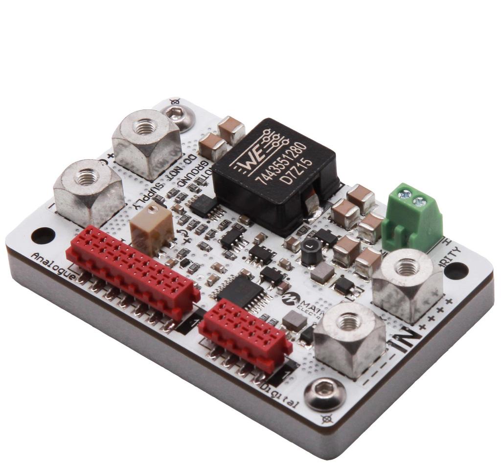
7 9. Pin and terminal functions Please, note polarity! Never ground any lead of the output, this may cause permanent damage to the laser diode and the driver! Never use any grounded probes (e.g. from the oscilloscope) at the output! Control pins are not isolated! Terminals Terminal Description Vin+ Connect to the positive terminal of the power supply. Please, note polarity! Please, pay attention to the markings! Vin- LD+ LD- Connect to the negative terminal of the power supply. Please, note polarity! Connect to the laser diode anode. Please note polarity! Grounding this terminal may cause permanent damage to the driver. Connect to the laser diode cathode. Please note polarity! Grounding this terminal may cause permanent damage to the laser diode. Controls Description 1 Analogue control connector 2 Current limit adjustment potentiometer 3 Digital control connector 6
 6 Interlock (duplicates pin 5 of analogue control connector) 7 Crowbar status (duplicates pin 3 of analogue control connector) 8 GND (connected to Vin- terminal) Analogue control connector")

8 Digital control connector Wurth WR-MM or TE Connectivity Pin Description 1 UART RXD 2 RS-232 RXD 3 UART ТXD 4 RS-232 TXD 5 +5V auxiliary (duplicates pin 4 of analogue control connector) 6 Interlock (duplicates pin 5 of analogue control connector) 7 Crowbar status (duplicates pin 3 of analogue control connector) 8 GND (connected to Vin- terminal) Analogue control connector Wurth WR-MM or TE Connectivity PIN I/O Name Description 1 I Enable High = operates; Low = stop. Internally pulled down. TTL or CMOS signals only. 2 GND Connected to Vin- terminal. 3 O Crowbar status High = fault; Low = normal operation. Internally pulled down. 4 +5V Auxiliary +5V power supply. Up to 200mA output current capability. 5 I Interlock Open = locked; Low = operates. Internally pulled up. 6 O Over-temperature warning High = t > 60 C; Low = t < 58 C. Internally pulled down. 7 GND Connected to Vin- terminal. 8-15V Auxiliary -15V power supply. Up to 20mA output current capability. 9 O Voltage monitor 0-10V = 0-10V at the output V Auxiliary +15V power supply. Up to 20mA output current capability. 11 O Current monitor 0-5V = 0-15А at the output. 12 GND Connected to Vin- terminal. 13 I Current set 0-5V = 0-15А at the output. 14 NTC Interlock Connect NTC thermistor 10k between this pin and GND. 7
9 10. Analogue control description Enable The enable pin is active high 3.3V and 5V compatible logic input. Driver operates when enable pin is high. To ensure correct start-up without overshoot, the soft-start sequence initiates when the enable pin becomes high. The enable pin can be used for QCW operation. The output may be pulsed by applying a TTL square signal to enable pin. Crowbar status Crowbar status pin reports the status of the protection shorting crowbar clamp across the output. The crowbar will short the output while over-current shutdown and over-temperature shutdown. While the protection shutdown the enable pin is ignored. Disconnect the driver from power to reset the protection status. Interlock The Interlock pin must be connected to GND in order for output current to be delivered. It can be used for external interlock e.g. door or over-temperature switches. Over temperature warning When the temperature of driver PCB exceeds 60 C the over-temperature warning will go high to indicate driver is in danger of shutting down due to over-temperature condition. When temperature of driver PCB exceeds 80 C, the driver will stop. The driver can be restarted when the temperature drops to 58 C. Voltage monitor The output voltage of the driver can be monitored by voltage monitor. 0-10V = 0-10V with +/-2% accuracy. The voltage is measured between LD+ and LD- terminals. Current monitor The output current of the driver can be monitored by current monitor. 0-5V = 0-15А with +/-2% accuracy. Current set The driver output current is set by applying an analog signal to the current set pin. 0-5V = 0-15А. The current set pin can be used for analogue modulation by applying sign, square or ramp signal with the DC component. Analogue modulation amplitude depends on frequency. Please, control the output current while using this feature. If you use arbitrary/function generator or lab PS for current set, make sure it is in High Z mode. Please, control the current set and current monitor pin voltages while getting started. NTC Interlock Thermistor connection. Allows you to measure the temperature of a laser or other devices. The measurement result is readable by the digital interface. Set upper and lower limits of the temperature at the outlet of which driver operation is blocked. When the temperature returns to the specified range, the driver operation resumes. 8
10 11. How to get started 1. Unpack your driver; 2. Connect a dummy load (e.g. a Schottky diode) to the LD- and LD+ terminals. Please note polarity; 3. Connect the controls (analogue and/or digital); 4. Connect the power supply. Please note polarity; 5. Rotate the current limit potentiometer counterclockwise several times; 6. Turn on the power supply; 7. Set the current equal to the desired current limit threshold; 8. Enable the driver; 9. Rotate the potentiometer slowly while the crowbar status pin becomes high; 10. Restart the power supply to reset protection; 11. Make sure the over-current protection limit is set right; 12. Make sure that all controls are working; 13. Turn off the power supply and disconnect a dummy load; 14. Connect the laser diode to the LD- and LD+ terminals. Please note polarity. 12. Cooling The driver produces up to 6W of losses. Thus the base plate has to be mounted on a thermal conduction surface to ensure proper operation and prevent an over-temperature shutdown. If the conduction cooling is not enough an additional cooling may be achieved by placing the driver into the airflow of a fan. 13. Internal protections Several security features protect the laser diode and driver from damage. Reverse diode protects the laser diode from reverse currents. In case of an over-current or an over temperature condition, the control logic disables the driver and the output shorts by a crowbar clamp. A softstart mechanism slowly raises the current at startup to protect the laser diode against current overshooting. 14. Digital control description When the input voltage applied the driver is always in analogue current set, external enable and allowing interlock state. Any other state should be set any time after powering the driver if needed. Default serial port settings: Baud rate Data bits Stop bits Parity Flow control none none Data exchange between the driver and the PC is only initiated by the PC. All commands are sent in plain text format. All commands are sent with prefix. Number of command follows the prefix without any symbols. If there is the value after the command they separates with space symbol. The command ends with carriage return symbol. 9
11 The format of the command to set the value (P-type); Number of Value byte Comment 1 P (50h) Set prefix 2-5 Number of the parameter Hex-number of the parameter. For example, 0100h 6 space symbol (20h) 7-10 New value of the parameter Hex-value of the parameter. For example, 0000h 11 return carriage symbol<cr> (0Dh) End of the command The device does not respond to P-type commands by default. (see section the protocol extension ) You can request the value of parameter by the J-type command. The device will return a value of requested parameter. The format of the command to get the value (J-type) Number of Value byte Comment 1 J (4Ah) Request prefix 2-5 Number of the parameter Hex-number of the parameter. For example, 0100h 6 return carriage symbol<cr> (0Dh) End of the command The format of the response Number of byte Value Comment 1 K (4Bh) Response prefix 2-5 Number of the parameter Hex-number of the requested parameter 6 space symbol (20h) 7-10 Returned value of the parameter Hex-value of the parameter 11 return carriage symbol<cr> (0Dh) End of the command If the device could not recognize a command, it returns an error message with error code. The format and codes of errors Error (returned command) E0000 E0001 E0002 K Reasons (one or few) 1) Internal buffer of device is overflowed. 2) Cannot find <CR> (0x0D) or\and <LF> (0x0A). 3) Format of command is invalid. 1) Unknown command (it does not P- or J-type command). 2) The device failed to correctly interpret a command. The CRC of received command (see section the protocol extension ). Request or set the parameter that does not exist. 10
12 Available parameters and its description Action Frequency (0.1 Hz) Duration (0.1 ms) Current (0.01 A) R/W Value R/W 0100 Minimum R 0101 Maximum R 0102 Value R/W 0200 Minimum R 0201 Maximum R 0202 Value R/W 0300 Minimum R 0301 Maximum R 0302 Measured value (0.1A) R 0307 Current set calibration (0.01%) 2 Value R/W 030E Voltage (0.1 V) Measured value R 0407 State of the device (bit mask) Stateofthe device (bit mask) Start (Enable) Stop (Disable) Internal current set External current set External Enable Internal Enable Allow Interlock Deny Interlock Deny NTC Interlock 0008h 0010h 0020h 0040h 0200h 0400h 1000h 2000h 4000h Allow NTC Interlock 8000h 0 bit 1 Device is powered on (always = 1) 1 st bit 0 Stopped; 1 Started 2 nd bit 4 th bit 6 th bit 7 th bit Current set: 0 External; 1 Internal Enable: 0 External; 1 Internal External NTC Interlock: 0 Allowed; 1 Denied Interlock: 0 Allowed; 1 Denied W 0700 R 0700 Serial number Return the hex-value of the serial number R 0701 HEXnumber of parameters 2 Default % (2710h), calibration range is from 95.00% (251Ch) to % (2904h). 11
13 Information about the purpose and possibilities of the device Information about parameters that you can change (bit mask) Lock status (bit mask)* NTC sensor temperature (0.1 ) PCB temperature (0.1 ) Type of device 0-3 bits Appointment 4-7 bits Flags CW driver 6 pulse driver 1 Independent unit 8 supports RS supports USB 10 supports LAN 11 supports TEC 0 bit 1 the device supports this option 1 st bit Frequency 2 nd bit Duration 3 rd bit Current 0 bit Reserve 1 st bit Interlock 3 rd bit Over current 4 th bit Overheat (warning) 5 th bit External NTC Interlock R 0702 R 0703 R 0800 Lower limit R/W 0A05 Upper limit R/W 0A06 Measured value R 0AE4 B 25/100 R/W 0B0E Measured value R 0AF4 *If temperature of the device reaches the over temperature warning threshold the overheat flag will be set. If the device is in over temperature protection state, then it will be set overheat and over current flags together. The maximum duration depends on the set value of the frequency. When you change frequency, a new value of the maximum duration is compute automatically. The duration of pulse cannot be less than 2 ms and more than period of frequency minus 2 ms. For low frequencies the duration cannot be more than 5000 ms. Set the zero frequency to switch the device into CW mode or set not zero frequency value to switch the device into QCW (long pulses) mode. If you try to set a value more or less than limits, then the value will be rounded to limit. Any attempts to set a new state of the device, except start, forcibly switch the device to the state stop. Some states of the device are mutually exclusive, for example, if you set Ext. Enable, then you will not be able to set the state start. If you send start and stop commands to each other, the device will save all parameters in the internal memory. The saving process lasts about 300 ms. In this time the device does not respond to any actions. The device is able to save the next parameters in the internal memory: Frequency with limits; Duration with limits; Current with limits and calibration; Temperature limits and B 25/100 ; Settings of the RS protocol extension (see section «the protocol extension»). 12
14 15. Digital control description (extended) WARNING! Extended protocol recommend for advanced users only. In addition, it might be use for integration of the device with other devices. Use the parameter number 0704h for configure the extended protocol. In extended protocol, you can enable and disable the next options: checksum (CRC 8-bit CCITT), return a new value of parameter after P-type commands, change baud-rate, change protocol-mode (text-plain or binary). The description of the protocol extension command Action Information about the extended protocol Configuring of the extended protocol 0 bit 1st bit 2nd bit 3-5 bits 6th bit On checksum (CS) 0002h 1 Off checksum 0004h 1 Return a new value for P-type commands 0008h 1 Do not return answer for P-type commands 0010h 3 Set new baudrate(baud) 4 Text-plain mode on 5 1 the device supports this option Checksum (1 on, 0 off) Return a new value for P- type commands (1 on, 0 off) Baud - rate (default) Data exchange mode (1 binary, 0 text-plain) 0100h h h h A0h h R\W R 0704 W 0704 HEX-number of parameters Binary mode on 0400h 3 In binary mode the specified commands are ignored by the device 4 Here are binary numbers 5 For more information, see section binary mode 13
15 Text-plain mode All commands in text-plain mode should be in ASCII. WARNING! If you enable the checksum it will change format of commands. After <CR> symbol you will be write 2 bytes of checksum and last byte will be <LF> (0Ah new line symbol). Checksum is computed for all bytes of command before checksum bytes (including<cr> symbol). All answers of the device will also contain a checksum, including K-type and E-type answers. Checksum is computed by CRC-CCITT-8 algorithm. This is the main difference between the format of commands for the extended protocol and standard protocol. The format of commands for enabled checksum Number of Value byte Comment 1 P,J,K,E Type of command 2-5 Number of parameter Hex-number of value 6 space symbol (20h) (does not use for J and E-type commands) 7-10 New value of the parameter Hex-value of parameter (does not use for J and E-type commands) 11 return carriage symbol<cr> End of value (0Dh) Checksum CRC checksum of the first 11 bytes (for J and E- type commands checksum is computed for the first 6 bytes), including <CR> symbol. 14 new line symbol<lf> (0Ah) End of command Possible problems 1. The device waiting for symbol <LF>. If <LF> symbol does not received and buffer is overflowed, then all symbols after overload will be processed as a new command. The device returns an error. In this case, it is recommended to send the <LF> symbol. The device will generate an error and clear the buffer for the next command. 2. All symbols after the <LF> symbol will be processed as a new command. 14
16 Binary mode The binary mode has a significant difference. In this mode, data are exchanged in binary form. Length of any type of command is 8 bytes! In this mode, next options are always enable and you cannot disable it: return a new value of parameter for P-type commands and checksum. The format of binary mode commands is represented in table 8. The format of binary mode commands Number of byte Value Comment 1 Type of command 50h (P- ascii) Set a new value of parameter 4Ah (J- ascii) Get a value of parameter 4Bh (K- ascii) Answer of the device 45h (E- ascii) Error 2-3 Number of parameter Hex-number of parameter 4-5 Value of parameter Hex-value of parameter. This value is STRICTLY REQUIRED in the binary mode. If this value does not make sense, it will be returned as 0000 (K or E-type commands) or you should set it field to any value (for P or J-type commands). 6 return carriage symbol <CR> (0Dh) End of value 7 Checksum CRC checksum of the first 11 bytes (for J and E- type commands checksum is computed for the first 6 bytes), including <CR> symbol. 8 new line symbol <LF> (0Ah) End of command 15
17 16. Mechanical dimensions All dimensions are in millimeters. 16
Before powering on your driver, read this manual thoroughly. If you have any doubt or suggestion, please do not hesitate to contact us!
 Laser diode driver Datasheet & User Manual Before powering on your driver, read this manual thoroughly. If you have any doubt or suggestion, please do not hesitate to contact us!, 37 Sedova St, Off 209,
LD6015. Datasheet & Manual. 1. Features. 3. Description. 2. Applications. 4. Absolute maximum ratings* 5. Recommended operating conditions
 LD6015 Datasheet & Manual 1. Features Low current ripple No need to adjust voltage Soft-start Adjustable overcurrent limit Thermal warning and shutdown Reverse current protection Crowbar circuit protection
Before powering on your driver, read this manual thoroughly. If you have any doubt or suggestion, please do not hesitate to contact us!
 Laser diode driver Datasheet & UserManual Before powering on your driver, read this manual thoroughly. If you have any doubt or suggestion, please do not hesitate to contact us!, 37 Sedova St, Off 209,
manufactured by SF8150-ZIF14
 manufactured by manufactured by SF8150- ZIF14 Butterfly packaged laser diode controller Datasheet & Users Manual Before powering on your driver, read this manual thoroughly. If you have any doubt or suggestion,
HM9708 HM9708. Battery-Powered Equipment Motherboard USB Power Switch USB Device Power Switch Hot-Plug Power Supplies Battery-Charger Circuits DC+ VIN
 200mΩ Power Distribution Switches Features 200mΩ Typ. High-Side MOSFET 0.8A Current Limit (V IN =3.0V) Wide Input Voltage Range: 2V ~ 5.5V Soft Start Thermal Protection Small SOT-23-5 Package Minimizes
up7535 Dual-Input Triple-Output Power Multiplexer in PSOP-8L for USB High Side Switch General Description Ordering Information Applications
 Dual-Input Triple-Output Power Multiplexer in PSOP-8L for USB High Side Switch The up7535 is a current limited, dual-input triple-output power multiplexer acting as a high side switch for USB applications
PLD Series +5V Laser Diode Drivers
 PLD Series +5V Laser Diode Drivers General Description The PLD series of Laser Diode Drivers combines the high performance you expect from a Wavelength component with two distinct improvements: low voltage
T1DP 0v High Voltage Desk Top Power Supply. Operators Manual
 Contents: 1. General information 2. Technical Data 3. Front panel 4. Operation 5. Polarity setting 6. Control via RS232 Interface 7. Desk information T1DP 0v High Voltage Desk Top Power Supply Operators
WS4601 WS4601. Descriptions. Features. Applications. Order information. 80mΩ, Current Limited, Power Distribution Switch
 80mΩ, Current Limited, Power Distribution Switch www.sh-willsemi.com Descriptions The is high-side switch with ultra-low ON resistance P-MOSFET. Integrated current-limit function can limit inrush current
Thermoelectric Cooler Controller TED1000
 Thermoelectric Cooler Controller TED1000 Operating Instructions MANUAL-TED1000-1.0 Aug 2015 Rev.1 2 Contents 1 General... 4 1.1 Warranty and Assistance... 4 1.2 Maintenance... 4 1.3 General Safety Considerations...
MP6219 5V, 1A 2A Programmable Current Limit Power Distribution Switch
 The Future of Analog IC Technology MP6219 5V, 1A 2A Programmable Current Limit Power Distribution Switch DESCRIPTION The MP6219 is a protection device designed to protect circuitry on the output from transients
2 AA Cell to 3.3V USB On-The-Go Devices White LED Drivers Handheld Devices. The HM3200B is available in the 6-pin SOT23-6.
 Low Noise, Regulated Charge Pump DC/DC Converter Features Fixed 3.3V ± 4% Output VIN Range: 1.8V to 5V Output Current: 100mA Constant Frequency Operation at All Loads Low Noise Constant Frequency (1.2MHz)
Pin # Name Type Description. 3, 7 GND Signal Ground Signal ground pin. Connect the POT, DAC and/or the DAC grounds to here.
 FEATURES Power Supply Voltage Range:.1V 6V High Efficiency: 90% Maximum Output Current: A Current Output Noise:
DS Wire Digital Thermometer and Thermostat
 www.maxim-ic.com FEATURES Temperature measurements require no external components with ±1 C accuracy Measures temperatures from -55 C to +125 C; Fahrenheit equivalent is -67 F to +257 F Temperature resolution
Sierra Dual 24 Volt Brushless DC Motor Controller Product Specification. Assembly 025F0348
 Sierra Dual 24 Volt Brushless DC Motor Controller Product Specification Assembly Revision History ECN # Date Rev Description By EC77363 03/15/17 A Initial Release K. Jones EC81620 11/15/17 B Added Agency
Elotech Standard Protocol. for Single R8200 SC
 Elotech Standard Protocol interface description / network protocol for Single R8200 SC ELOTECH Industrieelektronik GmbH Verbindungsstraße 27 D - 40723 HILDEN FON +49 2103 / 255 97 0 FAX +49 2103 / 255
Features. V CC 2.7V to 5.5V 10k OVERCURRENT GND NC
 MIC225/275 MIC225/275 Single-Channel Power Distribution Switch MM8 General Description The MIC225 and MIC275 are high-side MOSFET switches optimized for general-purpose power distribution requiring circuit
Brushless DC Motor Controller Product Specification Assembly 025F0200
 Product Specification Assembly 025F0200 Revision History ECN # Date Rev Description By EC40382 071811 A Initial Release D. Stahl EC81620 11/15/17 B Added Agency Approval S. Lavey Page 1 of 11 Table Of
DIO V Current Limited Load Switch
 Rev 1.0 DIO7527 Features Input voltage range: 2.7V to 5.5V 2A Maximum Load Current 70mΩ typical R DS(ON) 70μA quiescent current Under-Voltage Lockout High precision over current trigger point Open-drain
Brushless DC Motor Controller Product Specification Assembly 025F0219
 Product Specification Assembly Revision History ECN # Date Rev Description By EC46310 6/14/12 A Initial Release Z. Sheu EC63683 01/27/15 B Correct interface connector part number D. Stahl EC81620 11/15/17
Thermo Electric Cooling Temperature Controller TEC Controller / Peltier Driver ±10 A / up to ±21 V
 Thermo Electric Cooling Temperature Controller TEC Controller / Peltier Driver ±10 A / up to ±21 V TEC-1089 HW v1.70 OEM TEC Controller Features The TEC-1089 is a specialized TEC controller / power supply
High-side Power Distribution Switch NCT3521U
 High-side Power Distribution Switch NCT3521U -Table of Content- 1. GENERAL DESCRIPTION...1 2. FEATURES...1 3. APPLICATIONS...2 4. PIN CONFIGURATION AND DESCRIPTION...2 5. TYPICAL APPLICATION CIRCUIT...3
Thermo Electric Cooling Temperature Controller TEC Controller / Peltier Driver ±4 A / up to ±21 V. Miniature OEM TEC Controller
 Thermo Electric Cooling Temperature Controller TEC Controller / Peltier Driver ±4 A / up to ±21 V TEC-1091 Miniature OEM TEC Controller Features The TEC-1091 is a specialized TEC controller / power supply
MIC2546/2547. Features. General Description. Applications. Typical Application. Dual Programable Current Limit Switch
 Dual Programable Current Limit Switch General Description The MIC2546 and MIC2547 are integrated high-side dual power switches optimized for low loss dc power switching and other power management applications,
Features. 10k. 10k ON/OFF. 1µF OVERCURRENT OVERCURRENT. Typical Two-Port Bus-Powered Hub
 MIC2536 Dual USB Power Distribution Switch Final Information General Description The MIC2536 is a cost-effective high-side power switch, with two independently controlled channels, optimized for buspowered
Overvoltage-Protection Controllers with a Low RON Internal FET MAX4970/MAX4971/MAX4972
 19-4139; Rev 1; 8/08 Overvoltage-Protection Controllers General Description The family of overvoltage protection devices features a low 40mΩ (typ) R ON internal FET and protect low-voltage systems against
EFE300 / EFE400 EFE300M / EFE400M
 EFE300 / EFE400 EFE300M / EFE400M AC/DC Power Supply Series APPLICATION NOTE 68892 EFE300_400 App note 8.doc Document Number 68892 Page 1 of 13 1. INPUT... 3 AC INPUT LINE REQUIREMENTS... 3 2. DC OUTPUT...
V PP IN V CC3 IN V CC5 IN EN0 EN1 MIC2561 V CC5_EN V CC3_EN
 MIC2561 PCMCIA Card Socket and V PP Switching Matrix Final Information General Description The MIC2561 & V PP Matrix controls PCMCIA (Personal Computer Memory Card International Association) memory card
HX4002 HX1001. White LED Backlighting Li-Ion Battery Backup Supplies Local 3V to 5V Conversion Smart Card Readers PCMCIA Local 5V Supplies
 HX1001 Low Noise, Regulated Charge Pump DC/DC Converter Features Fixed 5V±4% Output VIN Range: 2.7V ~ 5V Output Current: up to 250mA (V IN =4.5V) Low Noise Constant Frequency Operation Shutdown Current:
ORDERING INFORMATION. OPERATION Measuring Temperature A block diagram of the DS1621 is shown in Figure 1. DESCRIPTION ORDERING PACKAGE
 AVAILABLE Digital Thermometer and Thermostat FEATURES Temperature measurements require no external components Measures temperatures from -55 C to +125 C in 0.5 C increments. Fahrenheit equivalent is -67
Thermo Electric Cooling Temperature Controller TEC Controller / Peltier Driver ±10 A / up to ±21 V
 Thermo Electric Cooling Temperature Controller TEC Controller / Peltier Driver ±10 A / up to ±21 V TEC-1089 HW v2.00 OEM TEC Controller Features The TEC-1089 is a specialized TEC controller / power supply
Silvertel. Ag Features. 2. Description. Compliant with PoH and IEEE802.3at Type 1(af) & Type 2. Small SIL package size 50.
 & Type 2. Small SIL package size 50.") Silvertel V1.0 Aug 2012 Datasheet Pb 1. Features Compliant with PoH and IEEE802.3at Type 1(af) & Type 2 Small SIL package size 50.8mm (L) x 35mm (H) Low cost Output power up to 95W Minimal (low cost) external
Silvertel V1.0 Aug 2012 Datasheet Pb 1. Features Compliant with PoH and IEEE802.3at Type 1(af) & Type 2 Small SIL package size 50.8mm (L) x 35mm (H) Low cost Output power up to 95W Minimal (low cost) external
WS3210C62 WS3210C62 Over-Voltage Protection Load Switch Descriptions CSP-9L (Bottom View) Pin Configuration (Top View)
 Pin Configuration (Top View)") Over-Voltage Protection Load Switch http://www.sh-willsemi.com Descriptions The features a low R ON internal High Voltage Switch and an input range of absolute maximum 30V. An internal input clamp is capable
Over-Voltage Protection Load Switch http://www.sh-willsemi.com Descriptions The features a low R ON internal High Voltage Switch and an input range of absolute maximum 30V. An internal input clamp is capable
LDN Series Laser Diode Drivers
 The New LDN series laser diode drivers are the second generation of precision CW/Pulsed diode drivers offered by Lumina Power. Building on more than a decade of experience in laser diode driver technology
It is the installer's responsibility to follow all instructions in this manual and to follow correct electrical practice.
 MCD Modbus Module Instructions Important User Information INSTALLATION INSTRUCTIONS: MCD MODBUS MODULE Order Code: 175G9000 1. Important User Information Observe all necessary safety precautions when controlling
Before powering on your unit, read this manual thoroughly and make sure your understood it fully.
 User Manual Rev. 1411 LDP-CW 90-10 Before powering on your unit, read this manual thoroughly and make sure your understood it fully. Please pay attention to all safety warnings. If you have any doubt or
Before powering on your unit, read this manual thoroughly and make sure you understood everything.
 1 User Manual Rev. 1811 LDP-CW 20-50 Before powering on your unit, read this manual thoroughly and make sure you understood everything. Please pay attention to all safety warnings. If you have any doubt
AIC A Dual USB High-Side Power Switch FEATURES DESCRIPTION APPLICATIONS TYPICAL APPLICATION CIRCUIT
 1.0A Dual USB High-Side Power Switch FEATURES 2.7V to 6.5V Input Voltage Range 1.0A Dual Continuous Load Current 100mΩ High-Side P-MOSFET Switch 20Ω Open-Drain Over-Current Flag Output 80uA Quiescent Supply
HARDWARE MANUAL TMCM-1613 TMCM-1613-REC. Hardware Version V TRINAMIC Motion Control GmbH & Co. KG Hamburg, Germany.
 MODULES FOR BLDC MOTORS MODULES Hardware Version V 1.10 HARDWARE MANUAL + + TMCM-1613 + + Single Axis BLDC Controller / Driver Block-commutation Hall-sensor based Analog+digital inputs / outputs Up-to
Brushless DC Motor Controller Product Specification Assembly 025F0095
 Product Specification Assembly 025F0095 Revision History ECN # Date Rev Description By N/A 1/23/06 1 First issue A. Meeuwsen N/A 2/07/06 2 Added content A. Meeuwsen 06008 3/13/06 A Release for document
Type Version Ordering Code Package PEB 2025-N V 1.5 Q67100-H6300 P-LCC-28-R (SMD) PEB 2025-P V 1.5 Q67100-H6241 P-DIP-22
 PEB 2025-P V 1.5 Q67100-H6241 P-DIP-22") ISDN Exchange Power Controller (IEPC) PEB 2025 CMOS IC Features Supplies power to up to four transmission lines CCITT recommendations compatible for power feed at the S interface Each line is individually
ISDN Exchange Power Controller (IEPC) PEB 2025 CMOS IC Features Supplies power to up to four transmission lines CCITT recommendations compatible for power feed at the S interface Each line is individually
Applications Military (Airborne, ground-fix, shipboard), Ruggedized, Telecom, Industrial
, Ruggedized, Telecom, Industrial") M4268 6U VPX / VITA 62 COMPLIANT, SIX OUTPUTS DC/DC Up to 1200W CONVERTERS Applications Military (Airborne, ground-fix, shipboard), Ruggedized, Telecom, Industrial Special Features VITA 62 standard compliant
M4268 6U VPX / VITA 62 COMPLIANT, SIX OUTPUTS DC/DC Up to 1200W CONVERTERS Applications Military (Airborne, ground-fix, shipboard), Ruggedized, Telecom, Industrial Special Features VITA 62 standard compliant
RT mΩ Power Distribution Switches. General Description. Features. Pin Configurations. Applications. Ordering Information
 100mΩ Power Distribution Switches General Description he is an integrated 100mΩ power switch for self-powered and bus-powered Universal Series Bus (USB) applications. A built-in charge pump is used to
Techcode TD5830A/B. 3A Low Dropout Regulator with Enable. General Description. Features. Applications. Package Types DATASHEET
 General Description Features The TD5830 is a high performance positive voltage regulator designed for use in applications requiring very low Input voltage and very low dropout voltage at up to 3 amps.
BCT mA Buck/Boost Charge Pump LED Driver
 BCT3140 GENERAL DESCRIPTION The BCT3140 is a current-regulated charge pump ideal for powering high brightness LEDs for camera flash applications. The charge pump can be set to regulate two current levels
LDY Series CW/QCW Laser Diode Drivers
 The LDY series is a new family of OEM laser diode drivers with all the performance of Lumina's flagship LDD line of laser diode drivers, as well as additional functions including pulsing capability, over-temperature
MasterFlux 48V Cascade BLDC Motor Controller Product Specification 030F0137
 MasterFlux 48V Cascade BLDC Motor Controller Product Specification 030F0137 Revision History Page 1 of 11 Date ECN Rev Description By 09/01/10 EC34869 A Initial Release D. Stahl 07/14/11 EC39745 B Updated
WS3210 WS3210. Over-Voltage Protection Load Switch. Descriptions. Features. Order information. Applications.
 Over-Voltage Protection Load Switch http://www.sh-willsemi.com WS3210 Descriptions The WS3210 features a low internal High Voltage Switch and an input range of absolute maximum 30V. An internal input clamp
DS1821 Programmable Digital Thermostat and Thermometer
 ma www.maxim-ic.com FEATURES Requires no external components Unique 1-Wire interface requires only one port pin for communication Operates over a -55 C to +125 C (-67 F to +257 F) temperature range Functions
Thermo Electric Cooling Temperature Controller Dual TEC Controller / Peltier Driver 2x (±16 A / up to ±31 V) OEM Dual-Channel TEC Controller
 OEM Dual-Channel TEC Controller") Thermo Electric Cooling Temperature Controller Dual TEC Controller / Peltier Driver 2x (±16 A / up to ±31 V) TEC-1123 OEM Dual-Channel TEC Controller Features The TEC-1123 is a specialized TEC controller
Thermo Electric Cooling Temperature Controller Dual TEC Controller / Peltier Driver 2x (±16 A / up to ±31 V) TEC-1123 OEM Dual-Channel TEC Controller Features The TEC-1123 is a specialized TEC controller
PCI-FPGA-1B User Guide
 PCI-FPGA-1B User Guide Rev 1.0 (Nov. 2012) Port City Instruments, LLC 8209 Market Street, Suite A271 Wilmington, NC 28411 (Tel) 866-456-2488 (Web) www.portcityinstruments.com Copyright 2012 Port City Instruments,
SGM mA, Low Power, Low Dropout 3 -Terminal, Linear Regulators
 3 -Terminal, Linear Regulators GENERAL DESCRIPTION The series low-power, low-noise, low-dropout, CMOS linear voltage regulators operate from a 2.5V to 5.5V input voltage. They are the perfect choice for
Maximum Power Dissipation 0.67W Operating Temperature Range 40 C to 85 C Storage Temperature Range 55 C to 150 C
 Description The ACE345E is a load switch which provides full protection to systems and loads which may encounter large current conditions. ACE345E offers a 95mΩ current-limited switch which can operate
LDD M SERIES INSTRUCTION MANUAL LDD M SERIES
 TM LDD M SERIES LDD M SERIES INSTRUCTION MANUAL P O Box Bozeman, MT 9 Phone (0) -90 Fax (0) -9 email sales@wavelengthelectronics.com www.wavelengthelectronics.com TABLE OF CONTENTS Features... Customer
+60V Simple Swapper Hot-Swap Switch
 19-2850; Rev 0; 4/03 +6 Simple Swapper Hot-Swap Switch General Description The is a fully integrated Simple Swapper hot-swap switch for positive supply rails. The device allows the safe insertion and removal
SLD-CS-series Compact High Power Broadband Light Source Modules.
 Superlum Broadband Light Sources SLD-CS-series Compact High Power Broadband Light Source Modules. Technical Product Specification Document ID: SL.RD.04.002.150508 December 2015 Revision: 002 ATTENTION
1. Introduction. 2. Installation MODBUS INTERFACE
 5551.C 8473.C MODBUS INTERFACE PIM-MB-1 Modbus Interface 1. Introduction AuCom soft starters can be controlled and monitored across an RS485 serial communication network using the Modbus RTU and AP ASCII
PT SERIES SIP Package
 FEATURES Industry Standard SIP 8 Package 3 Watts Isolated Output 2:1 Input Range Regulated Outputs Up to 86 % Efficiency -40 C to +85 operating temperature range Remote On/Off logic control Continuous
LDD CW Laser Diode Drivers
 LDD CW Laser Diode Drivers The LDD series are the industrial standard for OEM laser diode drivers and are ideal for high power applications where economy is important and performance cannot be compromised.
LM3526 Dual Port USB Power Switch and Over-Current Protection
 LM3526 Dual Port USB Power Switch and Over-Current Protection General Description The LM3526 provides Universal Serial Bus standard power switch and over-current protection for all host port applications.
+3.0V to +5.5V USB Power Control Switch
 SP55 +3.0V to +5.5V USB Power Control Switch Compliant to USB Specifications +3.0V to +5.5V Input Voltage Range Open Drain Error Flag Output.7V Undervoltage Lockout 500mA Minimum Continuous Load Current.5A
EFE300 / EFE400 EFE300M / EFE400M
 EFE300 / EFE400 EFE300M / EFE400M AC/DC Power Supply Series APPLICATION NOTE 68892 EFE300_400 App note 3.doc Document Number 68892 Page 1 of 11 1. INPUT... 3 AC INPUT LINE REQUIREMENTS... 3 2. DC OUTPUT...
ASI. Switched-Capacitor Boost Converter 3.3V-5.0V 100mA GENERAL DESCRIPTION FEATURES APPLICATIONS
 ASI Technical Data Sheet Switched-Capacitor Boost Converter 3.3V-5.0V 100mA FEATURES Switched-Capacitor Step-Up Operation Input Range: 2.7V to 5.0V Output Voltage: 3.3V-5.0V (programmable) Output Current:
G5803 1A Single Cell Li-Ion Battery Linear Charger
 1A Single Cell Li-Ion Battery Linear Charger Features No External Power MOSFET, Sense Resistor or Blocking Diode Required 1% Regulation Voltage Accuracy Programmable Constant Charge Current Limit up to
MIC2544A/2548A. General Description. Features. Applications. Typical Application. Programmable Current Limit High-Side Switch
 Programmable Current Limit High-Side Switch General Description The MIC2544A and MIC2548A are integrated, high-side power switches optimized for low loss DC power switching and other power management applications,
Installation and operation manual ReciFlow Gas
 Installation and operation manual ReciFlow Gas 1 1. Measurement principle... 3 2. Installation... 5 3. Operation... 7 4. Electrical interfaces... 11 5. Communication protocol... 14 6. Software update and
User-configurable Resolution. 9 to 12 bits (0.5 C to C)
") AT30TS75A 9- to 12-bit Selectable, ±0.5 C Accurate Digital Temperature Sensor DATASHEET See Errata in Section 12. Features Single 1.7V to 5.5V Supply Measures Temperature -55 C to +125 C Highly Accurate
AT30TS75A 9- to 12-bit Selectable, ±0.5 C Accurate Digital Temperature Sensor DATASHEET See Errata in Section 12. Features Single 1.7V to 5.5V Supply Measures Temperature -55 C to +125 C Highly Accurate
DS1625. Digital Thermometer and Thermostat FEATURES PIN ASSIGNMENT
 DS1625 Digital Thermometer and Thermostat FEATURES Temperature measurements require no external components Measures temperatures from 55 C to +125 C in 0.5 C increments. Fahrenheit equivalent is 67 F to
MP5007 5V, 1A- 5A Programmable Current Limit Switch
 The Future of Analog IC Technology DESCRIPTION The MP5007 is a protection device designed to protect circuitry on the output (source) from transients on input (V CC ). It also protects V CC from undesired
Fiber optic Switch. eol 1x2 1x4 2x2. eol 1x8 1x12 1x16 OPERATION MANUAL
 Fiber optic Switch eol 1x2 1x4 2x2 eol 1x8 1x12 1x16 OPERATION MANUAL CONTENTS Product Specification Features / Applications / Technology. 3 Optical Characteristics. 4 Electrical & Environmental Characteristics.
Rev Carbon Dioxide (CO2) Gas Sensor. TG100 User Manual
 Gas Sensor. TG100 User Manual") Rev. 2.93 TG100 User Manual The TG100 measuring carbon dioxide (chemical formula CO2) is a NDIR (Non-Dispersive Infrared) gas sensor. As it is contactless, it has high accuracy and longer life than sensors
Rev. 2.93 TG100 User Manual The TG100 measuring carbon dioxide (chemical formula CO2) is a NDIR (Non-Dispersive Infrared) gas sensor. As it is contactless, it has high accuracy and longer life than sensors
Before powering on your unit, read this manual thoroughly and make sure you understood it fully.
 User Manual Rev. 15.03 LDP-CW 20-50 Before powering on your unit, read this manual thoroughly and make sure you understood it fully. Please pay attention to all safety warnings. If you have any doubt or
DS WIRE INTERFACE 11 DECOUPLING CAP GND
 Rev ; 4/3 Hex Nonvolatile Potentiometer with General Description The contains six 256-position nonvolatile (NV) potentiometers, 64 bytes of NV user EEPROM memory, and four programmable NV I/O pins. The
AIC1520. Ferrite Bead GND. *33µF, 16V Tantalum, or 100µF, 10V Electrolytic Bold line indicate high-current traces. USB High-Side Power Switch
 USB High-Side Power Switch FEATURES 120mΩ (5V Input) High-Side MOSFET Switch. 500mA Continuous Load Current. 80µA Typical On-State Supply Current. Current-Limit / Short Circuit Protection. Thermal Limiting
MP5013A 5 V, 5 A Programmable Current-Limit Switch with Over-Voltage Clamp and Slew-Rate Control in TSOT23-8
 The Future of Analog IC Technology MP5013A 5 V, 5 A Programmable Current-Limit Switch with Over-Voltage Clamp and Slew-Rate Control in TSOT23-8 DESCRIPTION The MP5013A is a protection device designed to
SP V to +5.5V USB Power Control Switch Compliant to USB Specifications +3.0V to +5.5V Input Voltage Range Open Drain Error Flag Output 2.7V Un
 SP55 +3.0V to +5.5V USB Power Control Switch Compliant to USB Specifications +3.0V to +5.5V Input Voltage Range Open Drain Error Flag Output.7V Undervoltage Lockout 500mA Minimum Continuous Load Current.5A
MIC2027/2077. Features. General Description. Applications. Typical Application. Quad USB Power Distribution Switch
 Quad USB Power Distribution Switch General Description The MIC2027 and MIC2077 are quad high-side MOSFET switches optimized for general-purpose power distribution requiring circuit protection. The MIC2027/77
OEM QCL Controller. Quantum Cascade Laser Diode Driver with Integrated TEC Controller. Data Interfaces: Gbit Ethernet USB 2.
 OEM QCL Controller Input Characteristics: Features DC Input Voltage: 12 24 V Output Stage Laser Diode Driver: Laser diode (compliance) voltage: 14 V Current: Up to 1.5 A General Description: The contains
CPS Industrial Power Supply
 CPS Industrial Power Supply Power Supply Specification Model Number: FSAK C Series Industrial quality, 1U high, multiple output power supply AC Input: full range, active PFC. DC Output: 6 configurable,
Vorne Industries. Model 77/232 Serial Input Numeric 3" Display User's Manual
 Vorne Industries Model 77/232 Serial Input Numeric 3" Display User's Manual 1445 Industrial Drive Itasca, IL 60143-1849 (630) 875-3600 Telefax (630) 875-3609 Page 2 Model 77/232 Serial Input Numeric 3"
AC/DC Power Supply Series APPLICATION NOTE
 CFE400M AC/DC Power Supply Series APPLICATION NOTE CFE400M Apps Notes Iss 3 Document Number 72768 Page 1 of 18 Contents Contents... 2 1. INPUT... 3 AC INPUT LINE REQUIREMENTS... 3 2. DC OUTPUT... 4 OUTPUT
Digital Thermometer and Thermostat
 General Description The DS75 digital thermometer and thermostat provides 9, 10, 11, or 12-bit digital temperature readings over a -55 C to +125 C range with ±2 C accuracy over a -25 C to +100 C range.
SN8200 LI+ DUAL BATTERY CONTROLLER
 LI+ DUAL BATTERY CONTROLLER GENERAL DESCRIPTION The SN8200 is a highly integrated IC to serve as the control logic for a system with multiple power sources. It integrates a mini-charger s path power MOS
DS1845 Dual NV Potentiometer and Memory
 www.maxim-ic.com FEATURES Two linear taper potentiometers -010 one 10k, 100 position & one 10k, 256 position -050 one 10k, 100 position & one 50k, 256 postition -100 one 10k, 100 position & one 100k, 256
Pin # Name Type Description
 Figure 1. Photo of Actual FEATURES High Efficiency: 90% Constant Current Output Maximum Output Current: 3A Current Output Noise: 0.0% High Stability: 0ppm/ C PWM Switching Frequency Synchronizable Zero
A Issue A Original. Instruction Manual. nxds Serial Comms Interface
 Instruction Manual A735-01-860 Issue A Original nxds Serial Comms Interface Description nxds6i nxds10i nxds15i nxds20i Item Number A735-01-983 A736-01-983 A737-01-983 A738-01-983 nxds6ic nxds10ic nxds15ic
Sierra 80 Volt Brushless DC Motor Controller Product Specification
 Sierra 80 Volt Brushless DC Motor Controller Product Specification Assembly 025F0135 600A0588 Rev. B January 29, 2010 025F0135 Brushless DC Motor Controller Page 1 Revision History ECN # Date Rev Description
USB-SD MP3 Module Manual
 USB-SD MP3 Module Manual WT9501M03 www.elechouse.com Copyright reserved by elechouse Features www.elechouse.com Can play 8 ~ 320Kbps MP3 audio files; Support maximum capacity of 32G Byte SD card; Support
PART TOP VIEW ADDR2 ADDR3 ADDR4 SELECT S/H CONFIG V L DGND V SS AGND IN CH. Maxim Integrated Products 1
 9-675; Rev ; 4/ 32-Channel Sample/Hold Amplifier General Description The MAX567 contains 32 sample-and-hold amplifiers driven by a single multiplexed input. The control logic addressing the outputs is
Rev Carbon Dioxide (CO2) Gas Sensor. TG100 User Manual
 Gas Sensor. TG100 User Manual") Rev. 2.5 TG100 User Manual The TG100 measuring carbon dioxide (chemical formula CO2) is a NDIR (Non-Dispersive Infrared) gas sensor. As it is contactless, it has high accuracy and longer life than sensors
Rev. 2.5 TG100 User Manual The TG100 measuring carbon dioxide (chemical formula CO2) is a NDIR (Non-Dispersive Infrared) gas sensor. As it is contactless, it has high accuracy and longer life than sensors
Pin # Name Type Description
 Figure 1. Photo of actual FEATURES High Efficiency: 90% Constant Current Output Maximum Output Current: 00mA Current Output Noise: 0.0% High Stability: 0ppm/ C PWM Switching Frequency Synchronizable Zero
Digital Thermometer and Thermostat in SOT23
 General Description The digital thermometer and thermostat provides temperature readings that indicate the device s temperature. Thermostat settings and temperature readings are all communicated to/from
PI5USB2549 USB Charging Port Controller and Load Detection Power Switch
 Features Supports DCP Modes per USB Battery Charging Specification 1.2 Supports Shorted Mode per Chinese Telecommunication Industry Standard YD/T1591-2009 Supports non-bc1.2 Charging Modes by Automatic
DC/DC Point-of-Load (POL) Converter Input: 2.4 to 5.5Vdc or 8.3 to 14Vdc, Output: Vout = 0.75 to 3.3Vdc or 0.75 to 5.0Vdc, I out = 6A, 10A or 16A
 Converter Input: 2.4 to 5.5Vdc or 8.3 to 14Vdc, Output: Vout = 0.75 to 3.3Vdc or 0.75 to 5.0Vdc, I out = 6A, 10A or 16A") TOS Series Application Note DC/DC Point-of-Load (POL) Converter Input:. to 5.5Vdc or 8.3 to 1Vdc, Output: Vout =.75 to 3.3Vdc or.75 to 5.Vdc, I out = A, 1A or 1A (Pending) Applications Intermediate Bus
TOS Series Application Note DC/DC Point-of-Load (POL) Converter Input:. to 5.5Vdc or 8.3 to 1Vdc, Output: Vout =.75 to 3.3Vdc or.75 to 5.Vdc, I out = A, 1A or 1A (Pending) Applications Intermediate Bus
Silvertel. Ag Features. 2. Description. Type 4 PSE Compliant with IEEE802.3bt(Draft V3.2)
") Silvertel V1.0 May 2018 Datasheet Pb 1. Features Type 4 PSE Compliant with IEEE802.3bt(Draft V3.2) Backward compatible to IEEE802.3at Type 1(af) & Type 2 Small DIL package size 51mm (L) x 35mm (W) x 7mm
Silvertel V1.0 May 2018 Datasheet Pb 1. Features Type 4 PSE Compliant with IEEE802.3bt(Draft V3.2) Backward compatible to IEEE802.3at Type 1(af) & Type 2 Small DIL package size 51mm (L) x 35mm (W) x 7mm
2. Terminal arrangement TEMPERATURE CONTROLLER KT2 COMMUNICATION INSTRUCTION MANUAL. (Fig. 2-1)
") COMMUNICATION INSTRUCTION MANUAL TEMPERATURE CONTROLLER No.KTC3E2 2006.08 To prevent accidents arising from the misuse of this controller, please ensure the operator receives this manual. For this product
COMMUNICATION INSTRUCTION MANUAL TEMPERATURE CONTROLLER No.KTC3E2 2006.08 To prevent accidents arising from the misuse of this controller, please ensure the operator receives this manual. For this product
ILI2511. ILI2511 Single Chip Capacitive Touch Sensor Controller. Specification ILI TECHNOLOGY CORP. Version: V1.4. Date: 2018/7/5
 Single Chip Capacitive Touch Sensor Controller Specification Version: V1.4 Date: 2018/7/5 ILI TECHNOLOGY CORP. 8F., No.1, Taiyuan 2 nd St., Zhubei City, Hsinchu County 302, Taiwan (R.O.C.) Tel.886-3-5600099;
STBC ma standalone linear Li-Ion battery charger with thermal regulation. Description. Features. Applications
 800 ma standalone linear Li-Ion battery charger with thermal regulation Description Datasheet - production data Features Programmable charge current up to 800 ma No external MOSFET, sense resistors or
SGM2031 Low Power, Low Dropout, RF - Linear Regulators
 RF - Linear Regulators GENERAL DESCRIPTION The series low-power, low-dropout, CMOS linear voltage regulators operate from a 2.5V to 5.5V input voltage in an ultra small package. They are the perfect choice
FXL6408 Fully Configurable 8-Bit I 2 C-Controlled GPIO Expander
 October 2012 FXL6408 Fully Configurable 8-Bit I 2 C-Controlled GPIO Expander Features 4X Expansion of Connected Processor I/O Ports Fully Integrated I 2 C Slave 8 Independently Configurable I/O Ports Low-Power