User Manual TRB4000TL/TRB5000TL/TRB6000TL/TRB8000TL/TRB9000TL/ TRB010KTL
|
|
|
- Lynn McBride
- 5 years ago
- Views:
Transcription
1 User Manual TRB4000TL/TRB5000TL/TRB6000TL/TRB8000TL/TRB9000TL/ TRB010KTL
2 Contents Copyright Declaration Introduction Introduction How to Use this manual Applied Designations (Warning, Caution, Note) Important Safety Information General Safety Rules for Working on Electrical Equipment System Sizing Technical Description of Inverters Mechanical design Electrical system design The illustration of derating and limit the input power Operation mode illustration of the inverter Wait mode Check mode Normal mode Fault mode Flash mode Shut down Installation and startup Installation precaution Install steps Electrical connection Connection to the grid (AC output) Connection to PV generator (DC input) Test run Human Machine Interface Control and Display Panel LED Display LCD Display Function Keys User Manual 1
3 Configure Energy yield Inverter state Device Information log Information Display of Fault Communication and Monitoring Communication Interfaces Communication RS-232 Communication for Three inverter type RS-485/422 Communication WiFi/GPRS/Ethernet Communication USB Communication Monitoring Maintenance and Repair Routine maintenance Notes of maintain or service Safety for maintain or service Technical data Warranty Standard Warranty Period Extension of Warranty Liability Insurance Warranty Claim Procedure Exclusion of Warranty Claims Service after Warranty Expiration Contact Information Appendix A: FAQ (Frequently asked questions) Appendix B: Abbreviation User Manual
4 Copyright Declaration The copyright of this manual belongs to Trannergy Co., Ltd.. Any corporation or individual should not plagiarize, partially copy or fully copy it (including software, etc.), and no reproduction or distribution of it in any form or by any means. All rights reserved. Trannergy reserves the right of final interpretation. This manual is subject to change according to user s or customer s feedback. Please check latest version at: User Manual 3
5 1. Introduction 1.1. Introduction This manual describes Trannergy solar inverters TRB4000TL/ 5000TL/ 6000TL/ 8000TL/ 9000TL/010KTL. These products are among the most technologically advanced and efficient inverters on the market and are designed to ensure a stable power supply for many years. The TRB inverters is a transformerless based inverter How to Use this manual Please read the safety instructions in this manual first. Throughout the manual it is assumed that the reader is familiar with AC and DC installations and knows the rules and regulations for electrical equipment and for connecting it to the utility AC grid. It is especially important to be familiar with the general safety rules for working with electrical equipment Applied Designations (Warning, Caution, Note) Throughout the manual important information is shown at different levels depending on the character of the information, as shown here: Safety information important for human safety. Violation of warnings may result in injury to persons or death. Information important for the protection of property. Violation of this type of information may cause damage and loss of property. Useful additional information or Tips and Tricks" on specific subjects Important Safety Information Read this before installing, operating or maintaining the inverter. Before installation: Check for damage to inverter and packaging. If you are in doubt, please contact your supplier before installing the inverter. Check the voltages of the solar modules and make sure they are within the limits of the Trannergy inverter specifications before connecting them to the inverter. Installation: Only trained and authorized personnel familiar with local electrical codes may install 4 User Manual
6 the inverter. For optimum safety, please follow the steps described in this manual. Keep in mind that the inverter has two voltage carrying sides, the PV input and the AC grid. Disconnecting the inverter: Always disconnect the AC line first! Afterwards disconnect the PV lines. Note that the inverter can still be charged with very high voltages at hazardous levels even when it is disconnected from grid/mains and solar modules. Wait at least 5 min. before proceeding, after having disconnected from grid and PV panels. operating the inverter: Before connecting the AC grid to the inverter, make sure that the installation cover is mounted again. The inverter must not be open during operation. Maintenance and modification: Only authorized personnel are allowed to repair or modify the inverter. To ensure optimum safety for user and environment, only the original spare parts available from your supplier should be used. Functional safety parameters: Unauthorized changes of functional safety parameters may cause injury or accidents to people or inverter. Additionally it will lead to the cancelling of all inverter operating approval certificates. The Trannergy inverters in the TRB range are all designed according to international safety requirements. If non-original spare parts are used, the compliance with CE guidelines in respect of electrical safety, EMC and machine safety is not guaranteed General Safety Rules for Working on Electrical Equipment All persons installing, maintaining or servicing inverters should be trained in and have experience with the general safety rules to be observed when working on electrical equipment. Installation and service personnel should also be familiar with local requirements, rules and regulations as well as safety requirements. To provide a general guideline for safety precautions, five well-known and widely accepted rules are repeated below. The list should by no means be considered as exhaustive. The person performing work on electrical equipment is responsible for the safety of persons and property! Disconnecting Disconnect all cables supplying voltage to the working place before starting any work. Please note that a lack of voltage is no guarantee that disconnection has been performed. Protecting against reconnection Prevent the system from reconnecting by marking, closing or locking off the work area. Unintentional reconnection may result in severe accidents. Checking that system is voltage free Ascertain conclusively by means of a voltage tester that the system is voltage free. User Manual 5
7 Check all terminals to ensure that the system is voltage free (on each individual conductor). Covering adjacent voltage-carrying components and preventing persons from gaining access to them Cover up all voltage-carrying system components that can harm you while working. Make sure that danger areas are clearly marked System Sizing When dimensioning a photovoltaic system, it must be ensured that the open circuit voltage of the PV string never exceeds the maximum permissible input voltage of 1000V DC. The PV string open circuit voltage during parallel string operation is 910V. Higher voltages may result in permanent damage to the inverter. The selection of PV string output should be based on the optimum utilization of the invested capital compared to the expected annual energy yield from the system. This optimization depends on local weather conditions and should be considered in each individual case. The inverter incorporates an input power limiting device, which automatically keeps the power at levels that are safe for the inverter. The limitation depends mainly on internal and ambient temperatures. The limitation is calculated continuously and always allows the maximum possible amount of energy to be produced. Please use the tool supplied by Trannergy when dimensioning a photovoltaic system. 6 User Manual
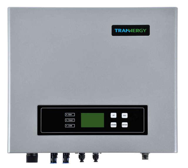
8 2. Technical Description of Inverters 2.1. Mechanical design Figure 2-1 shows the outline dimensions of TRB4000TL/5000TL/6000TL/8000TL/9000TL/010KTL Figure 2-1 Outline dimensions of TRB4000TL/5000TL/6000TL/8000TL/9000TL/010KTL The AC output terminal is most length part at the bottom of inverter, so take care of the AC output terminals, do not make it stand on the ground or other materials while moving or lifting the inverters otherwise will make terminal damaged. DC SWITCH DC INPUT TERMINALS COMMUNICATION TERMINALS AC OUTPUT TERMINALS Figure 2-2 Electrical Terminals of TRB4000TL/5000TL/6000TL/8000TL/9000TL/010KTL For safety reasons, the use of a DC switch is recommended. Between the PV modules and the power modules may be mandatory in some countries. User Manual 7


9 2.2. Electrical system design Figure 2-3 wiring diagram of the whole TRB4000TL/5000TL/6000TL/8000TL/9000TL/010KTL system. Please refer to chapter 4 for the detail connecting and install methods The illustration of derating and limit the input power To avoid inverter to be damaged by over temperature or over current. Not output power when the temperature of power devices is over 85 or the ambient temperature is over 76. Derate the output power linearly when the temperature of power devices is between or the ambient temperature is between User Manual
10 3. Operation mode illustration of the inverter Our inverter has five operation modes during the whole work process; they are wait, check, normal, fault and flash modes. Its detail illustration is shown by Figure 3-1 below Wait mode Figure 3-1 State Machine of Inverter working mode When the input power by solar panel is not enough to let the power module work, it is at waiting mode. The inverter will wait until the input voltage is above 210Vdc and below 910Vdc, it turn to check mode Check mode When the inverter is power on, it will check isolation, HCT device, GFCI device, relay, fan, and soft start automatically in order. This can guarantee the inverter work normally and turn to normal operation mode Normal mode When the conditions above are satisfied, inverter will let the BOOST and inverter module work and turn to normal generating power mode. It will change the solar energy into electrical energy and fed it into grid based on advanced MPPT technology in order to absorb solar energy in maximum extent possible. It will also calculate the generated energy per day/per month/per year automatically, save User Manual 9
11 the number in EEPROM and the number can be read from the HMI Fault mode When there are fault during the inverter running, it will stop generating power and turn to fault mode and display the fault information on LCD. Before do this, it will store the generated power number into EEPROM automatically. Many not very serious fault will be cleared after 5s automatically and retry to run. If the serious fault generated, it will stay in the fault mode until the technical staff to solve the problem Flash mode Regardless the inverter running in which mode above, when there is the flash command, it will turn into flash mode and rewrite the firmware in DSP flash Shut down When the PV input voltage less than 150Vdc, the PV panel can t provide energy enough, so the inverter shut down automatically. When next day come, with the irradiance increasing, it will run again smoothly if there are no fault occurrence. 10 User Manual
12 4. Installation and startup 4.1. Installation precaution Warning! Before installation and maintenance, AC and DC side doesn t carry electricity, but if DC side is just disconnected, capacitance still contains electricity, so please wait for at least 5 minutes to ensure the capacitors completely release the energy and inverter is not electrified. Note! Inverters must be installed by qualified person. Trannergy assures the product guarantee of the TRB series inverters during five years after your purchase, if the installation site does not meet the instructions described in this manual, it is out of warranty. The warranty is limited to the costs of repair and/or replacement of the product by Trannergy only. Ventilation is very important to cool the inverter. For outdoors application, the inverter requires at least 300mm of clearance among the other units and 300mm of the ground or the roof. See Figure 4-1: 300mm 300mm 300mm 300mm 4.2. Install steps Figure 4-1 Distance required of Inverters Setp1: Drill six Ø10 holes in the wall according to the dimensions shows in Figure 4-2: User Manual 11
13 XΦ10,45-50mm,Deep 180 Note! Figure 4-2 Dimensions of drilling holes Keep drilling vertical to the wall, and don t shake when drilling to avoid damage to the wall. It need repositioning and drilling holes if the hole with much error. Step2: Put the expansion pipe showing in Figure 4-3 into the hole vertically, use hammer to tap the pipe into the wall completely. Figure 4-3 Expansion tube Step3: Put the mounting panel on the wall and twist the M8x50 screws into the expansion tube to fix the mounting panel. Figure 4-4 Install the mounting panel Setp4: Hung the inverter on to the mounting panel: 12 User Manual
 Attention Connection Procedure: Safeguard each inverter with an individual manual AC breaker in order that inverter can be safely disconnected under load when")
14 Figure 4-5 Hung the inverter 4.3. Electrical connection Connection to the grid (AC output) Attention Connection Procedure: Safeguard each inverter with an individual manual AC breaker in order that inverter can be safely disconnected under load when installation & maintenance Step1: Switch off the AC breaker secure against being switched back on inadvertently. Step2: strip the cable as the following figure: (Recommended cable specification:awg 10 without crimping terminal; AWG 12 with crimping terminal) Figure 4-6 Step3: AC female connector includes the following components: Figure 4-7 Step4: Put the wires through Screw Cap, Adapter Body of the AC female connector: User Manual 13

 Attention!")
15 Figure 4-8 Step5: Connect the cables according to the following pictures: PE N N L R T 1 2 S Figure 4-9 Attention! Please ensure the corresponding relationship between polarities the core cable and the hole of the terminal is correct. Step6: Screw these components tightly after connecting the wires: Figure 4-10 Step7: Connect AC female terminal to AC male terminal on inverter and then screw them together Connection to PV generator (DC input) Attention! Safeguard each inverter with an individual manual DC breaker in order that inverter can be safely disconnected under load when installation & maintenance. The breaker should have certain capacity of over current and over voltage. In addition, before cutting off the DC end connection. Please cut off the AC end connection at first. There are two MPPT trackers (A & B route) provided by the TRB4000TL /5000TL /6000TL /8000TL /9000TL/010KTL and each MPPT tracker provides a pair of DC input interface. 14 User Manual


16 Attention! Connectors must not be connected or disconnected under load! Figure 4-11 Step1: Assembly Instruction for the male side and female side connector: Strip cable.276 inches (9/32 ) - (7mm) and be careful NOT to nick conductors. Figure 4-12 Amphenol specified strip tool can be used in this step. Adjust the striper stopper and put the cable in corresponding notch to strip the length of 7mm. See below figures. Figure 4-13 Insert striped cable into contact barrel and insure all conductor strands are captured in the contact barrel and the conductors are visible in the contact barrel observation hole. See below figures. User Manual 15


17 Figure 4-14 Crimp contact barrel by using the hex crimping die. See below figures Figure 4-15 Amphenol specified crimping tool can be used in this step. Put the contact barrel with striped cable in the corresponding crimping notch and crimp the contact. See below figures. Figure 4-16 Insert contact cable assembly into back of male and female connector. A click should be heard or felt when the contact cable assembly is seated correctly. See below figures. Figure User Manual

")

18 Wrest the cap by using the torque of 2.6~2.9NM. Step2: Mate and separate Helios H4 connector: Figure 4-18 After wrest the cap tightly, align the 2 half connectors and mate them together by hand until a click is heard or felt. Figure 4-19 When the separation of connector is necessary, use the Amphenol specified tool (Ring tool or wrench tool) to separate. And while using the ring tool or wrench tool, please make sure the wedge side of the fingers faces the female connector and push the tool down. Then separate the connector by hand. See below figures. Figure 4-20 DANGER! DANGER to life due to potential fire or electric shock. NEVER connect or disconnect the DC connectors under load. User Manual 17
19 4.4. Test run Before turn on the inverter, please confirm: a) Three phase five wires (R/S/T/N/PE) cable correctly connected to the inverter AC side through AC circuit breaker; b) The DC cable connected correctly to the inverter DC side through DC circuit breaker, please be attention to the cable connected to the two string correctly and it s polarity; c) The unused terminals are covered. Turn on the inverter: Step1: Close the DC and AC circuit breaker; Step2: If the solar panels provide enough energy, the power module will work and the LCD panel will be lit; Step3: Then the inverter will turn into self-check mode and the LCD panel will display the remaining time of connect simultaneously; Step4: After the inverter turn into normal mode, it feed electrical energy into grid, and LCD panel will display the generated electrical energy. As long as the inverter works, it will automatically track the maximum power point to absorb the maximum energy from solar. When night comes, the irradiance is not strong enough to provide energy, the inverter will power off automatically. When the next day comes, the input voltage reaches the start value, it will start again automatically. 18 User Manual
.")
20 5. Human Machine Interface 5.1. Control and Display Panel Info provided here mainly includes LED display, LCD display, function keys and display fault etc. All function including parameter review, setting, and malfunction info etc can be realized at this interface. It is showing as the follow (Figure 5-1). H D A B C G E F Figure 5-1 Control and Display Panel Object A B C D E F G H Description Working normally (Green LED) Fault (Red LED) Communication (Yellow LED) EXIT (Function key) Down (Function key) OK (Function key) LCD display Up (Function key) TRB4000TL/5000TL/6000TL/8000TL/9000T/010KTL has 3 LEDs, 1 LCD and 4 function keys: LEDs Green LED: Working normally. Yellow LED: Communication. Red LED: Fault. LCD MONO LCD. Function keys OK Button: confirm the selection. UP Button: move cursor to up selection or increase the values. DOWN Button: move cursor to down or decrease the values. ESC Button: exit current menu into main menu. User Manual 19
21 5.2. LED Display TRB4000TL/5000TL/6000TL/8000TL/9000T/010KTL are equipped with three LEDs including Green, Yellow and Red which provide information about various operating status. Green LED The green LED lighting indicates that inverter is active and working normally. Otherwise, it indicates inverter shuts down or malfunction happens. When the grid shows 380V/50Hz and input voltage generated by PV modules is above 200V, the green LED lights up. Normally, this LED begins to light up in the morning when the sunshine intensity is enough and goes out when it gets dark. Yellow LED The yellow LED flashes during inverter communicating with other devices including DLU and PC etc through RS485 and goes out after the communication finishes. The yellow LED keeps on lighting during the software update; otherwise, inverter doesn t communicate with other devices, or burn, update the firmware etc. Red LED The red LED indicates that inverter has stopped feeding power into the grid because of fault, and the exact fault information will display on the LCD at the same time. The faults as follows in the table will activate the red LED. For details, please refer to table as below: LED Status Detailed Message Green Normal TRB inverters is working normally. Communication state TRB inverters is communicating with other devices. Yellow Red Burning software/ Software upgrade GFCI Failure AC HCT Failure Consistent Fault: DC inj. differs for M-S Consistent Fault: Ground I differs for M-S High DC Bus Utility Loss Ground I Fault Over Temperature in Inverter The firmware is upgraded. The GFCI detection circuit is abnormal. The AC output sensor is abnormal. Different measurements between Master and Slave for DC output current. Different measurements between Master and Slave for GFCI. DC Bus voltage is too High. No grid voltage detected. GFCI malfunction. Internal temperature of inverter is high. 20 User Manual

22 PV Over Voltage Fan Lock AC Voltage Out of Range Isolation Fault DC Injection High Consistent Fault Consistent Fault: Fac differs for M-S Consistent Fault: Vac differs for M-S AC Relay-Check Fail M-S Version Unmatched Fac Failure: Fac Out of Range EEPROM R/W Fail SPI Failure: Communication Fails between M-S PV input voltage surpasses the tolerable maximum value. Fan malfunction. The measured AC voltage is out of tolerable range. Isolation resistance of PV to earth is too low. The DC injection to grid is too high. Different measurements between Master and Slave. Different measurements between Master and Slave for grid frequency. Different measurements between Master and Slave for grid voltage. AC relay malfunction. Different CPU software version. The master frequency is out of tolerable range. EEPROM reading or writing error. Communication between microcontrollers fails LCD Display The LCD display shows parameters of inverters which can be set through function keys. On the top, it always shows working status and Ethernet status, The left area is for displaying parameter info or energy wave; On the right, it always shows power, E-today, E-total; At the bottom of LCD display, time and date will be shown (Figure 5-2 Main Interface 1) When press enter button, it will go into main menu, telling inverter state, energy yield, as well as device and malfunction info, and parameter setting; (Figure 5-2 Main Interface 2) A B F C D E Figure 5-2 Main Interface 1 User Manual 21


23 G Figure 5-3 Main Interface 2 H Figure 5-4 Main Interface 3 Object A B C D E F G H Description Working status of inverter and Ethernet Real-time power of inverter. Power generated today in kilowatt hours. Total power generated since inverter starting up. Display date & time. Specific parameters, curve display area. Main menu: generated inverter state, energy yield, parameter setting, device & malfunction info. Pull-down menu under main menu. Contents of menu: Function Inverter state Energy yield AC Parameter DC Parameter Frequency E-Week E-Month E-Year Content 22 User Manual

24 Settings Log Device Information Language and Time Safety Parameters Power Management Clear Data Ethernet Settings Error Information Serial number safety type version information Fault display: When fault happens, the specific fault information will show in main window on LCD display. At the same time, the red LED lights up and the green LED goes out. The following figure indicates that the fault No Utility happened. Figure 5-5 Fault Windows Now if enter into log, fault information of the latest 20 pieces can be reviewed Function Keys There are four function keys, by which users can choose menus on LCD and realize online parameter reviewing & setting etc Configure Language and Time In main menu, Move the cursor to settings by pressing the up or down key; Press the enter key, and then you will find a pull-down menu. Please move the cursor to Date Time by pressing the up or down key, and then press OK, you can set information of language, date and time. Figure 5-6 Language and Time Setting User Manual 23


25 Language setting When the cursor is at the Language column, you can choose Chinese, English or German etc, and then press enter, you can confirm Language setting. Date setting When the cursor is at the Date, at first you can set the Year by pressing the up and down keys. After finishing setting year, please press the down key and move to Month, press the enter key to confirm setting. set month also by pressing the up and down keys. Press the enter key to finish Month setting,after that, press the down key to Date, set date also by pressing the up and down keys. Later, press enter and you can finish t Date setting. Time setting When the cursor is at the Time, at first you can set Hour by pressing the enter key and then pressing the up and down keys, at last, pressing enter key to finish setting; When finishing setting the hour, please press the down key to Minute, set minute also by pressing the enter key and then pressing the up and down keys. at last, pressing enter key to finish setting. And then press the down key to second, set second also by pressing the enter key and then pressing the up and down keys, at last, pressing enter key to finish setting. Finally, please press OK. Notes: After setting the Language, Date and Time, press the down key to ok, and then press enter to save setting. If pressing esc to discard setting Safety Parameters Setting pressing the enter key, you will find a pull-down menu. Please move the cursor to Safety Parameters menu by pressing the up or down key, and then press enter key, you will come to the interface for Safe Parameter. At this interface, you can choose the last or the next parameter, or increase or decrease the parameters. These parameters contain Safety, Vpv-Start, T-start, Vac-Min, Vac-Max, Fac-Min, Fac-Max and so on. Notes: This operation step requires password (default value: 1001). Figure 5-7 Password Input Interface 24 User Manual


 If this operation is done, all the data in the memory will be cleared, so backup of all the data before clear is recommended. 5.4.")
26 Figure 5-8 Safety Parameters Setting After that, you can choose ok, Default to confirm parameter change, restore original data. Press OK and exit this interface to enter main menu Clear Data when pressing the enter key, you will find a pull-down menu. Choose Clear Data menu and press enter to get into data clearing state. In this menu, press OK to clear all the data in the memory, and if press esc exit this interface. Notes: Figure 5-9 Clear Data Verify Interface 1) This operation step requires password (default value: 1001). 2) If this operation is done, all the data in the memory will be cleared, so backup of all the data before clear is recommended Power Management Setting when pressing the enter key, you will find a pull-down menu. Choose Power Management menu and press enter to get into Power Management state. In this menu, press OK to set power limit and factor type, if choosing Default, data set default value. Figure 5-10 Power Management Interface User Manual 25


27 Energy yield Press the enter key, and then you will find a pull-down menu. Please move the cursor to E-Week by pressing the up or down key, then press enter, the relevant information will be shown. (E-Week is default status) Figure 5-12 week Energy Wave Using the same operating procedures, you can check E- Month, E-Year Inverter state Press the OK key, and then you will find a pull-down menu. Please move the cursor to inverter state by pressing the up or down key, and then press enter key, the related information at AC,DC, frequency and temperature will be shown. If you press ESC key, you can exit this interface Device Information Figure 5-13 Inverter state Interface Press the enter key and you will find main menu. Move the cursor to Device information by pressing the up or down key, and then press the enter key, you will find the information of Device Model, SN, HMI/SW, CU/SW etc. Press the esc key exit this interface. Figure 5-14 Device Information 26 User Manual


28 log Information Press the enter key and you will find main menu. Move the cursor to Log by pressing the up or down key, and then press the enter key, you will find the log fault column, including time fault happened and fault info. Press the esc key exit this interface. Log fault contains Error information of the latest 20 times; if you need more information, please derive from DLU Display of Fault Figure 5-15 Error Messages Interface When inverter cannot work normally and faults haven t been solved, the specific fault information will show in window on the LCD, showing when the fault happened and the error information. At the same time, the red LED lights up and the green LED goes out. The following figure indicates that the fault No Utility happened. Figure 5-16 Fault Windows Now if you want to view the fault info, you can find log under main menu. User Manual 27

29 6. Communication and Monitoring 6.1. Communication Interfaces This product has a communication interface RS-232,RS-485/422and WiFi/ GPRS/ Ethernet (optional). Operating information like output voltage, current, frequency, fault information, etc., can be delivered to PC or hardware storage devices or other monitoring equipment via communication interface Communication When user want to know the information of the power station and manage the entire power system. We offer below 4 type communications RS-232 Communication for Three inverter type RS-232 is one communication interface. It transmits the data between PC and one TRI series inverter (Figure 6-1). For communication cable, one end is male connector; the other end is female connector. The maximum length of the cable for RS-232 is 10 m. D B -9 R S -232 R S -232 C A B LE PIN1 PIN2 PIN3 PIN4 PIN5 PIN6 PIN7 PIN8 PIN9 NC TXD RXD NC GND NC NC NC NC Notes: Figure 6-1 RS-232 Communication Diagram If your computer doesn t have the DB9 communication interface, you can use RS232-USB cable to achieve this function. One inverter can only be communicated with one PC at the same time through RS-232 port. Thus this method is generally used for three inverter s communication, for examples, software updating and serviceman s testing. 28 User Manual

30 RS-485/422 Communication RS-485/422 is generally for multi inverters communication. It can communicate with and up to 32 inverters could communicate at the same time, but wire length should be 1200 m. Connect the system as blow (Figure 6-2), user can easily monitoring the PV power station. U S B T o R S /4 2 2 U S B R S /4 2 2 Figure 6-2 RS-485/422 Communication Diagram PIN1 PIN2 PIN3 PIN4 PIN5 PIN6 PIN7 PIN8 TXD+_RS-485/422 TXD-_RS-485/422 RXD+_RS-485/422 GND RXD-_RS-485/422 +7V/DC Notes: The wires connection sequence of two ends of a RS-485/422 cable is the same. 2 If customers communicate with inverter via RS-485/422, you can buy USB to RS-485/422 converters and install pvcs software. 3 TX termination of inverter connect with RX termination of USB to RS-485/422 converters, RX termination of inverter connect with TX termination of USB to RS-485/422 converters WiFi/GPRS/Ethernet Communication TRB inverters can be communicated with WiFi/ GPRS/ Ethernet. Trannergy can customize the required special device from customers to realize wireless communication USB Communication USB interface is specially designed for maintenance engineer to realize burning and updating of PCU firmware. User Manual 29
31 6.3. Monitoring Monitoring system is divided into local monitoring and remote monitoring 1. Local monitoring system System monitor PVCS should be configured to realize one PC communicates with multi inverters at the same time. Through PC PVCS could get real time PV plants operating data. Please see Installation Guide of PVCS for more information. The connected graph of the monitoring system, in which the multipoint communication of the inverters can be realized through RS-485/422 interface, is shown below (Figure 6-3). The software PVCS in the PC can handle real-time monitoring of max 32 inverters at the same time. USB USB To RS485/422 RS485/422 RS485/422 RS485/ Remote monitoring systems Figure 6-3 Monitoring Topology Diagram When users choose WiFi/GPRS/Ethernet communication, User can open a web browser and visit the portal website: after register and log in, you can monitor information of inverter. At Apple s and Android s app store, you can input the key words: Trannergy-log, then you can download and install the Trannergy-log to your Mobile equipment. After the download and installed, input your user name and password, then visit your station,(we supply a free demo, for the users who do not register)choose the power station and enter the main interface, then you the daily energy etc. will be displayed. Meanwhile, you can view the relevant date to view the curve. 7. Maintenance and Repair 7.1 Routine maintenance Generally, the inverter needn t to maintain or calibrate, but you need to ensure the heat sink uncovered by the dust or dirty things. In order to prove the inverter s normal function and long life, you best to clean the inverter and heat sink regularly and ensure there is enough space for air flow around the heat sink. You can use the compressed air, soft cloth or brush to clean the surface of inverter and heat sink. Please don t use water, corrosive chemicals or strong detergent to clean them. 30 User Manual
32 7.2 Notes of maintain or service When there are faults occurrences, the inverter can disconnect from grid automatically and send out fault or warning information. The simple fault approaches refer to appendix A (FAQ) please. 7.3 Safety for maintain or service Before you handle the fault, you must open the DC and AC circuit breaker first and prove others can t close it again without your permission. The inverter must only be opened by qualified personnel for repair. The inverter can still be charged with hazardous voltages even when it is disconnected from the PV modules and the grid. Measure the DC bus voltage, which must be lower than 48V, before starting work on the electronic system inside the cabinet. User Manual 31
33 8. Technical data MODEL TRB4000TL TRB5000TL TRB6000TL TRB8000TL TRB9000TL TRB010KTL Rated AC power 4000 W 5000 W 6000 W 8000 W 9000 W 9600 W Maximum AC power 4000 VA 5000 VA 6000 VA 8000 VA 9000 VA VA INPUT Maximum input power 4250 W 5250 W 6300 W 8400 W 9450 W W Maximum DC voltage in an open circuit 1000 Vdc 1000Vdc 1000 Vdc 1000Vdc 1000Vdc 1000Vdc MPP voltage range / rated input voltage Vdc / 240Vdc Vdc / 300Vdc Vdc / 350Vdc Vdc / 460Vdc Vdc / 520Vdc Vdc / 580Vdc Maximum input current 10 Adc / 10Adc 10 Adc / 10Adc 10 Adc /10Adc 10 Adc / 10Adc 10 Adc / 10Adc 10 Adc / 10Adc Startup voltage 180 Vdc 180 Vdc 180 Vdc 180 Vdc 180 Vdc 180 Vdc DC Switch integrated integrated integrated integrated integrated integrated Initial feeding voltage 210 Vdc 210 Vdc 210 Vdc 210 Vdc 210 Vdc 210 Vdc Number of inputs MPPT number OUTPUT Operating voltage 220Vac / 380 Vac or 230 Vac/ 400 Vac Number of grid phases Voltage Range Vac / 310 Vac Vac Frequency range 50 Hz, 60Hz / -5 Hz Hz Power factor -0,9-0,9 controllable Maximum current 7 Aac 8.5Aac 10Aac 12.5 Aac 14 Aac 14.6 Aac DC current injection (max.) <20 ma <20 ma <20 ma <20 ma <20 ma <20 ma Current Harmonic < 3% < 3% < 3% < 3% < 3% < 3% Distorsion(THDi) SYSTEM Maximum efficiency >98.1% >98.1% >98.1% >98.1% >98.1% >98.1% MPPT efficiency >99.9% >99.9% >99.9% >99.9% >99.9% >99.9% European efficiency >97,4% >97,4% >97,4% >97,6% >97,6% >97,6% Switching plan self-commutated, transformerless Detecting earth leakage Yes Yes Yes Yes Yes Yes Heat dissipation Convection MECHANICAL SPEC. Dimensions in mm 540 x 200 x470 Weight 23 Kg 23Kg 23 Kg 24Kg 24Kg 24Kg Protection class IP65 Display LCD 3.5 Inch Data interface RS232 / RS485 / Ethernet / WiFi / GPRS Noise emission < 35dB Ambient operating temp -25 C C (> 45 C derating) Casing Aluminium CERTIFICATIONS Safety compliance VDE AR-N-4105, VDE A1, CE, G83/2, UTE C15-712, MEA, PEA, AS4777, NB/T User Manual
34 9. Warranty 9.1. Standard Warranty Period For Trannergy inverters sold to UK, Netherlands, and Ireland, the standard warranty period is 120 months from the date of installation and no more than 126 months (10.5 years) from the date of shipment from Trannergy Co., Ltd. For Trannergy inverters sold to other countries, the standard warranty period for Trannergy inverter is 60 months from the date of installation and no more than 66 months (5.5 years) from the date of shipment from Trannergy Co., Ltd Extension of Warranty The purchaser may apply for a warranty extension up to 12 months following the installation date or 24 months from the date of shipment (whichever date comes first) from Trannergy by providing the serial number of the unit and purchased receipt. Extension warranty can be purchased for extra 5, 10 or 15 years for all inverters. Please refer to the Warranty Extension Order Form for more details Liability Insurance Trannergy inverters are insured up to a maximum of $3,000,000 by Chubb Insurance Company Limited Warranty Claim Procedure Please report defective device with a brief error description and SN code to our service mail or service hotline for registration. Alternatively, please contact your specific dealer or installer if your unit is defective or faulty. To claim the warranty under the warranty terms of Trannergy, you need to supply us with the following information and documentation regarding the faulty unit: ( to our service mail is high recommended) Fill the warranty card including the following information: Product Model No. (e.g. TRB6000TL ) and serial number (e.g. PCL6000N ); Error message on LCD screen (if available) or any information that would be helpful to describe the situation; Detailed information about the entire system (modules, circuits, etc.); Documentation of previous claims/exchanges (if applicable); Copy of the invoice and warranty certificate for the inverter; Copy of the installation receipt with installation date; After receiving above information, Trannergy will decide how to precede the service: Provide a replacement device of equivalent value according to model and age, and compensate the labor cost for the replacement, or; Perform on site replacement by Trannergy when necessary. In the case of an exchange, the remainder of the warranty entitlement will be transferred to the replacement device. In this event, you will not receive a new certificate, as this replacement will be noted by Trannergy. If the unit needs to be replaced following assessment, Trannergy will send a User Manual 33
35 replacement unit immediately. The defective inverter should be sent back to the closest Trannergy office by packing in its original package if possible or other comparable packaging Exclusion of Warranty Claims To provide better service to Trannergy s End Users, all Trannergy authorized Dealers or Distributors are requested to respond to End Users warranty claim. Trannergy will replace any products or parts of the product during the Warranty Period proved to be defective in design or manufacture. Any defect caused by the following circumstances will not be covered by the manufacturer s warranty (the Dealers or Distributors are responsible and authorized by Trannergy for the following investigation): Product modified, parts replaced or attempt to maintain; Changes, or attempted repairs and erasing of series number or seals by non Trannergy technician; Incorrect installation or commissioning; Failure to comply with the safety regulations (VDE-A-RN-4105, VDE0126 standards, etc.); The Product has been improperly stored (including stored over time) and damaged while being stored by the Dealer or the end user; Transport damage (including scratch caused by movement inside packaging during shipping). A Claim should be made directly to shipping company/insurance Company as soon as the container/packaging is unloaded and such damage is identified; Failure to follow any/all of the user manual, the installation guide and the maintenance regulations; Improper use or misuse of the device; Insufficient ventilation of the device; Influence of foreign objects and force majeure (lightning, grid overvoltage, severe weather, fire, etc.); Customers get the Trannergy product under improper transaction such as with legal dispute, unpaid debt, etc. During the warranty period more than 10 years and less than 25 years, the freight and replacement cost is covered by the customer, no matter how long the warranty is extended. Trannergy will offer a repaired product after receiving the defect product in those cases. Trannergy reserves the right of final interpretation of all the terms Service after Warranty Expiration For products which are out of warranty, Trannergy charges an on-site service fee, parts, labor cost and logistic fee to end-user which can be any/all of: On-site attendance fee: Cost of travel and time for the technician in attending on-site; Parts: Cost of replacement parts (including any shipping/admin fee that may apply); Labor: Labor time fee charged for the technician, who is repairing, maintaining, and installing (hardware or software) and debugging the faulty product; Logistic fee: Cost of delivery, tariff and other derived expense when defective products are sent from user to Trannergy or/and repaired products are sent from Trannergy to user; 34 User Manual
36 10. Contact Information If you have any further technical questions about our products, please contact us: Trannergy Co., Ltd Address: No.188 Weiwu Rd, Shanghai China Hotline: Trannergy UK Ltd Address: Mezzanine Floor 19, Crawford Street, London, W1H 1PJ Hotline: Trannergy Benelux Service Center Address: Loosterwegnoord 2J, 2161AP Lisse, The Netherlands Hotline: Trannergy Australia Service Center service@trannergy.com Hotline: +61 (0) Signature: Date: Mar For further information of Trannergy warranty regulation and reliability, please visit User Manual 35
37 Appendix A: FAQ (Frequently asked questions) Sometimes, the PV system does not work normally; we recommend the following solutions for average troubleshooting. This can help the technician to understand the problem and take a proper action. LCD display Possible actions Isolation Fault 1. Check whether the inverter is earthed and test impedance between PV (+) & (-) and the impedance must exceed 3MΩ; 2. Check whether the AC-side has contacts with earth. Ground Current Fault 1. The ground current is too high. 2. After cutting off the AC side connection, unplug the inputs from the PV generator and check the peripheral AC system. 3. After the cause is cleared, re-plug the PV panel and AC connection, and check PV inverter status. Clearable Fault Grid Fault Fac Over Range Vac Over Range Utility Loss 1. Wait for 5 minutes, if the grid returns to normal, PV inverter automatically restarts. 2. Make sure grid voltage and frequency meet the local specifications. 1. Grid is not connected. 2. Check grid connection cables. 3. Check grid usability. 4. If grid is ok and the problem exists still, maybe the fuse in the inverter is open, please call service. Over Temperature 1. The internal temperature of inverter is higher than specified normal value. 2. Find a way to reduce the ambient temperature. 3. Or move the inverter to a cooler environment. PV over Voltage 1. Check the open PV DC voltage, and see if it is greater than or too close to 900VDC 2. If PV DC voltage is less than 900VDC, and the problem still occurs, please call local service. Consistent Fault Disconnect PV (+) or PV(-) from the input, restart the inverter. Permanent Fault Relay-Check Fail 1. Disconnect all PV (+) or PV (-). DC INJ High 2. Wait for a few seconds. EEPROM R/W Fail 3. After the LCD switches off, reconnect and check again. SCI Failure AC HCT Fault GFCI Failure 4. If the problem remains, please call local service. If the PV DC voltage is higher than 200V, while the inverter still doesn t work, please call the local service. During periods of little or no sunlight, the inverter may continuously start up and shut down. This is due to insufficient power generated and it is normal working state. If sunlight strengthens or energy 36 User Manual
38 increase to support the inverter s startup, while the problems remain, please call service. Except the frequent problems as above, if you still have any problems which cannot be solved, please contact us and we will offer the best services as we can. Appendix B: Abbreviation AC DC DLU DSP EEPROM EMC EMI GFCI HCT HMI LCD LED MPPT PC PV PVCS SCI Alternating Current Direct Current Data Logger Unit Digital Signal Processing Electrically Erasable Programmable Read-Only Memory Electro Magnetic Compatibility Electro Magnetic Interference Ground Fault Circuit Interrupter Hall Current Transformer Human Machine Interface Liquid Crystal Display Light Emitting Diode Maximum Power Point Track Personal Computer Photovoltaic Photovoltaic Control System Serial Communication Interface User Manual 37
39 P/N: Ver: 00
User Manual TRI010KTL/TRI012KTL/TRI015KTL/TRI017KTL/TRI020KTL
 User Manual TRI010KTL/TRI012KTL/TRI015KTL/TRI017KTL/TRI020KTL Contents Copyright Declaration... 3 1. Introduction... 4 1.1. Introduction... 4 1.2. How to Use this manual... 4 1.3. Applied Designations
User Manual TRM025KTL/TRM030KTL/TRM033KTL/TRM035KTL
 User Manual TRM025KTL/TRM030KTL/TRM033KTL/TRM035KTL Contents 1. Introduction... 4 1.1. Introduction... 4 1.2. How to Use this manual... 4 1.3. Applied Designations (Warning, Caution, Note)... 4 1.4. Important
Global Network. Solar Grid Connected Inverter
 Global Network UK France Lithuania Denmark Belarus Netherlands Ukraine Germany Italy Hebei Mexico Senegal Jordan Jiangxi Japan Bangladesh Shanghai Guangzhou Thailand Sri Lanka Kenya Malaysia Chile Australia
GRID-TIED SOLAR INVERTER 1.5KW ~ 6.0KW V.1.2
 USER MANUAL MPI-1500/2000/3000/4000/6000 Series GRID-TIED SOLAR INVERTER 1.5KW ~ 6.0KW V.1.2 WWW.MPPSOLAR.COM WARNING: ONLY A CERTIFIED ELECTRICIAN OR TRAINED ASSEMBLING PROFESSIONAL SHOULD OPEN OR INSTALL
1.1 Validity Target group Retention of the manuals Regulations Technical rules Intended use...
 Table of Contents 1 About this manual... 3 1.1 Validity... 3 1.2 Target group... 3 1.3 Retention of the manuals... 3 1.4 Regulations... 3 2 Safety instructions and regulations... 4 2.1 Technical rules...
Solis Single Phase Inverter
 PV Grid Tie Inverter Solis Single Phase Inverter Installation and Operation Manual Ningbo Ginlong Technologies Co., Ltd. No. 57 Jintong Road, Binhai Industrial Park, Xiangshan, Ningbo, Zhejiang, 315712,
Solis Single Phase Inverter
 PV Grid Tie Inverter Solis Single Phase Inverter Installation and Operation Manual Ningbo Ginlong Technologies Co., Ltd. No. 57 Jintong Road, Binhai Industrial Park, Xiangshan, Ningbo, Zhejiang, 315712,
USER MANUAL INSTALLATION AND OPERATION
 USER MANUAL INSTALLATION AND OPERATION PV Inverter HNS1000TL-1/ HNS1500TL-1/ HNS2000TL-1/ HNS2500TL-1/ HNS3000TL-1/ HNS3600TL-1/ HNS4000TL-1 About Afore Afore New Energy Technology (Shanghai) Co., Ltd.,
SLK Grid PV-inverter (UL) Installation and Operation Manual
 Installation and Operation Manual") SLK Grid PV-inverter (UL) Installation and Operation Manual Only an electro-skilled person or trained assembly staff can install or open the Inverter. Before you start Thanks for purchasing SLK Grid PV-Inverter.
SLK Grid PV-inverter (UL) Installation and Operation Manual Only an electro-skilled person or trained assembly staff can install or open the Inverter. Before you start Thanks for purchasing SLK Grid PV-Inverter.
Solis Three Phase Inverter
 PV Grid Tie Inverter Solis Three Phase Inverter Installation and Operation Manual Ningbo Ginlong Technologies Co., Ltd. No. 57 Jintong Road, Binhai Industrial Park, Xiangshan, Ningbo, Zhejiang, 315712,
String Inverter (SUN2000-8/12KTL)
") String Inverter (SUN2000-8/12KTL) 2 MPPTs for versatile adaptions to different module types or quantities built up with different alignments 4 strings intelligent monitoring and 80% time saving for fault
String Inverter (SUN2000-8/12KTL) 2 MPPTs for versatile adaptions to different module types or quantities built up with different alignments 4 strings intelligent monitoring and 80% time saving for fault
-5K-2G. Solar PV Grid Tie Inverter. inverter. Installation and Operation Manual. 2013, Ningbo Ginlong Technologies Co., Ltd.
 Solar PV Grid Tie Inverter -5K-2G inverter Installation and Operation Manual Ver 1.0 Ningbo Ginlong Technologies Co., Ltd. No. 57 Jintong Road, Binhai Industrial Park, Xiangshan, Ningbo, Zhejiang, 315712,
GCI-2G-W Single Phase Inverter
 Wind Grid Tie Inverter GCI-2G-W Single Phase Inverter Installation and Operation Manual -US version Ningbo Ginlong Technologies Co., Ltd. No. 57 Jintong Road, Binhai Industrial Park, Xiangshan, Ningbo,
GCI-5K INSTALLATION AND OPERATOR S MANUAL
 GCI-5K INSTALLATION AND OPERATOR S MANUAL Grid-tied inverter for wind Ningbo Ginlong Technologies 1 INTRODUCTION 2 SAFETY GUIDELINES AND WARNINGS 3 INSTALLATION 3.1 Selecting a location for the inverter
ELV12 Series. Instruction Manual
 Instruction Manual TDK-Lambda BEFORE USING POWER SUPPLY UNIT Be sure to read this instruction manual thoroughly before using this product. Pay attention to all warnings and cautions before using the unit.
MT8050iE series. Installation Instruction (1) (2)
 (2)") MT8050iE series 3 Installation Instructions Installation Instruction Secure the operator panel in position, using all the fastening holes and the provided brackets and screws: (A) 1 Installation and Startup
MT8050iE series 3 Installation Instructions Installation Instruction Secure the operator panel in position, using all the fastening holes and the provided brackets and screws: (A) 1 Installation and Startup
INFO-PV_Inverter. User Manual INF-PVI 2000 INF-PVI 3000 INF-PVI 4000 INF-PVI 5000
 INFO-PV_Inverter User Manual INF-PVI 2000 INF-PVI 3000 INF-PVI 4000 INF-PVI 5000 VERSION 1.2 Contents 1 IMPORTANT SAFETY INSTRUCTIONS... 2 2 OVER REVIEW... 4 2.1 External dimensions... 4 2.2 Unit Description...
PV Rapid Shutdown device
 PV Rapid Shutdown device Installation and Operation Manual Solis-RSD-1G(1:1) Solis-RSD-1G(2:2) Manufacturer: Ginlong (Ningbo) Technologies Co.,Ltd., Ningbo, Zhejiang, P.R.China US Office: 565 Metro Pl.
HITACHI. EH-150 series PLC EH-RTD8 Resistance Temperature Detective input module Instruction manual. Safety precautions
 HITACHI EH-150 series PLC Resistance Temperature Detective input module Instruction manual Thank you for purchasing a Hitachi Programmable Logic Controller. To operate it safely, please read this instruction
Chameleon Stand-alone
 Quick Installation Guide Installation and Commissioning Chameleon Stand-alone Power Supply Module, 48 VDC, 650W, HE, IP65 Low Power Outdoor Applications 356849.03 Introduction Warnings..., page 3 Tools
GCI Three Phase Wind Inverter
 Wind Grid Tie Inverter GCI Three Phase Wind Inverter Installation and Operation Manual Ningbo Ginlong Technologies Co., Ltd. No. 57 Jintong Road, Binhai Industrial Park, Xiangshan, Ningbo, Zhejiang, 315712,
Line reactors SINAMICS. SINAMICS G130 Line reactors. Safety information 1. General. Mechanical installation 3. Electrical installation
 Safety information 1 General 2 SINAMICS SINAMICS G130 Mechanical installation 3 Electrical installation 4 Technical specifications 5 Operating Instructions Control version V4.7 04/2014 A5E00331462A Legal
F1000 User's Manual. (Version: V1.01)
") (Version: V1.01) Contents Chapter 1 Overview... 2 Chapter 2 Installation... 3 2.1 Installation guide... 3 2.1.1 Installation position... 3 2.1.2 NEMA4 standard installation... 3 2.1.3 Environment precautions...
(Version: V1.01) Contents Chapter 1 Overview... 2 Chapter 2 Installation... 3 2.1 Installation guide... 3 2.1.1 Installation position... 3 2.1.2 NEMA4 standard installation... 3 2.1.3 Environment precautions...
ILUMEN PID SOLUTION INDOOR OUTDOOR ILUMEN PIDBOX MINI INSTALLATION MANUAL. Ilumen PIDbox mini Version 1.5
 ILUMEN PID SOLUTION ILUMEN PIDBOX MINI INSTALLATION MANUAL INDOOR OUTDOOR Ilumen PIDbox mini Version 1.5 1 TABLE OF CONTENT 1 Information on this manual... 3 1.1 Validity... 3 1.2 Target group... 3 1.3
SUNNA SERIES PHOTOVOLTAIC INVERTER USER MANUAL SUNNA 1500TL / 2000TL / 3000TL / 4200TL / 5000TL
 SUNNA SERIES PHOTOVOLTAIC INVERTER USER MANUAL SUNNA 1500TL / 2000TL / 3000TL / 4200TL / 5000TL Contents Introduction...2 Important Safety Instructions...4 Product Overview...5 Installation...10 Front
Smart Grid Tie Microinverter User Manual
 Smart Grid Tie Microinverter User Manual Thanks for choosing Smart Microinverters. Read the following instruction carefully before installation and operating, install and operate as specified by this user
22-60VDC Grid Tie Microinverter User Manual
 22-60VDC Grid Tie Microinverter User Manual Thanks for using Smart Grid Tie Microinverters. Read the following instruction carefully before installation and operating, install and operate as specified
Power Supply. Users Guide PRODUCT MANUAL. WESTELL.COM Westell Technologies MNL rd
 PRODUCT MANUAL Power Supply Westell Technologies. 960-1152-MNL rd DISCLAIMER All information and statements contained herein are accurate to the best of Westell Technologies knowledge. Westell Technologies
Installation and Operations Manual INVOLAR MAC250 Microinverter
 Installation and Operations Manual INVOLAR MAC250 Microinverter Contact Information INVOLAR Corporation, Ltd. 887 Zuchongzhi Road, Build 84, Room 408, Shanghai, China 201203 Tel: 86-21-50272208 Fax: 86-21-50277705
SINAMICS G130. Terminal Module 150 (TM150) Operating Instructions 03/2013 SINAMICS
 Operating Instructions 03/2013 SINAMICS") SINAMICS G130 Operating Instructions 03/2013 SINAMICS s Safety information 1 General information 2 SINAMICS SINAMICS G130 Mechanical installation 3 Electrical installation 4 Technical specifications 5
SINAMICS G130 Operating Instructions 03/2013 SINAMICS s Safety information 1 General information 2 SINAMICS SINAMICS G130 Mechanical installation 3 Electrical installation 4 Technical specifications 5
H Series PLC. ! : Indicates Compulsion. EH-150 Analog input module EH-AXH8M Instruction manual. Safety precautions DANGER CAUTION COMPULSION
 H Series PLC EH-150 Analog input module EH-AXH8M Instruction manual Thank you for purchasing a Hitachi Programmable Logic Controller. To operate it safely, please read this instruction manual and all the
User Manual. 3KW/5KW PV Inverter
 User Manual 3KW/5KW PV Inverter (IP 20) Version: 1.0 Table Of Contents 1. Introduction... 1 1-1. Overview... 1 1-1. Affecting Factors for Performance of the Inverter... 1 2. Important Safety Warning...
2016 SIGLENT TECHNOLOGIES CO.,LTD
 Quick Strat SDM3045X Digital Multimeter QS06034-E01A 2016 SIGLENT TECHNOLOGIES CO.,LTD Copyright Information SIGLENT TECHNOLOGIES CO., LTD. All rights reserved. The information provided in this manual
INSTALLATION GUIDE DM-20 English Version 1.10 EN DM20 V1.10A
 www.supremainc.com INSTALLATION GUIDE DM-20 English Version 1.10 EN 101.00.DM20 V1.10A Contents Safety Instructions... 3 Components... 4 Front Side... 5 Installation Example... 6 Dimensions... 7 Installation...
Solis Three Phase Inverter
 PV Grid Tie Inverter Solis Three Phase Inverter Installation and Operation Manual -US version Ningbo Ginlong Technologies Co., Ltd. No. 57 Jintong Road, Binhai Industrial Park, Xiangshan, Ningbo, Zhejiang,
User Manual. Solar Inverter for Water Pump
 User Manual Solar Inverter for Water Pump SP Revival Series Version: 1.2 Table Of Contents ABOUT THIS MANUAL... 1 Purpose... 1 Scope... 1 SAFETY INSTRUCTIONS... 1 Inspection... 1 Installation... 1 Operation...
Industriefunkuhren. Technical Manual. Signal Converter. for DIN Rail Mounting Series 4800xx-yy ENGLISH
 Industriefunkuhren Technical Manual Signal Converter for DIN Rail Mounting Series 4800xx-yy ENGLISH Version: 01.01-19.07.2007 2 / 23 Signal Converter 4800 - V01.01 INPORTANT NOTES Downloading Technical
User Manual. 2.2KW/7.5KW/11KW Solar Inverter for Water Pump. Version: 1.8
 User Manual 2.2KW/7.5KW/11KW Solar Inverter for Water Pump Version: 1.8 Table Of Contents ABOUT THIS MANUAL... 1 Purpose... 1 Scope... 1 SAFETY INSTRUCTIONS... 1 Inspection... 1 Installation... 1 Operation...
SUN2000P-375 W Smart PV Optimizer. User Manual. Issue 01. Date HUAWEI TECHNOLOGIES CO., LTD.
 Issue 01 Date 2017-08-01 HUAWEI TECHNOLOGIES CO., LTD. 2017. All rights reserved. No part of this document may be reproduced or transmitted in any form or by any means without prior written consent of
Smart Grid Tie Microinverter User Manual
 Smart Grid Tie Microinverter User Manual Thanks for choosing Smart Microinverters. Read the following instruction carefully before installation and operating, install and operate as specified by this user
Serial PROFIBUS Interface
 Installation Manual Serial PROFIBUS Interface Version: EN-062016-2.3 Copyright 2016 Softing Industrial Automation GmbH Disclaimer of liability The information contained in these instructions corresponds
Resolver to Digital Expansion Board
 Resolver to Digital Expansion Board Catalog No. EXB009A01 Installation and Operating Manual 6/98 MN1313 Table of Contents Section 1 General Information............................. 1-1 Introduction....................................
ControlKeeper 4. General Information. Connecting Relay Loads. Installation Sheet. Getting Started. Power Supply Wiring. Mounting the Cabinet
 General Information ControlKeeper 4 Installation Sheet Model# CK4-120NO- Model# CK4-277NO The ControlKeeper-4 model is shipped in one package and is configured with either a 120V or a 277V transformer.
Installation and Operation Back-UPS BR1000G-IN / BR1500G-IN
 Installation and Operation Back-UPS BR1000G-IN / BR1500G-IN Important Safety Information Read the instructions carefully to become familiar with the equipment before trying to install, operate, service
Huawei Solar Product Training HUAWEI TECHNOLOGIES CO., LTD.
 Huawei Solar Product Training HUAWEI TECHNOLOGIES CO., LTD. Contents Overview of the Product Range Huawei Solar Inverter Technical Information Huawei Smartlogger Technical Information NetECO Portal Brief
TVAC25100 TVAC25110 User manual
 TVAC25100 TVAC25110 User manual Version 11/2010 Original user manual. Keep for future use. 12 Introduction Dear Customer, Thank you for purchasing this product. This product meets the requirements of the
Line reactors SINAMICS. SINAMICS G120P Line reactors. Safety information 1. General. Mechanical installation 3. Electrical installation 4
 Safety information 1 General 2 SINAMICS SINAMICS G120P Mechanical installation 3 Electrical installation 4 Technical specifications 5 Operating Instructions Control version V4.6 11/2013 A5E32845290B AA
MC 11 EB-2 Power supply cabinet with external bus, AC version
 MC 11 EB-2 Power supply cabinet with external bus, AC version USER/MAINTENANCE MANUAL 1 SLOT 0 SLOT 1 SLOT 2 SLOT 3 SLOT 4 SLOT 5 SLOT 6 SLOT 7 SLOT 8 SLOT 9 SLOT 10 SLOT 11 EB-2 (a) MC11 (b) (c) Figures
Operating instructions. Switching amplifier DN0210 DN / / 2015
 Operating instructions Switching amplifier DN0210 DN0220 UK 80011079 / 00 01 / 2015 Contents 1 Preliminary note...4 1.1 Symbols used...4 1.2 Warning signs used...4 2 Safety instructions...5 2.1 General...5
Operating and Installation Manual. EASYLAB Expansion modules Type EM-TRF for 230 V AC mains voltage
 Operating and Installation Manual EASYLAB Expansion modules Type EM-TRF for 230 V AC mains voltage Type EM-TRF-USV for 230 V AC mains voltage; provides uninterruptible power supply (UPS) The art of handling
INSTALLATION MANUAL SLI 50 INVERTER
 INSTALLATION MANUAL SLI 50 INVERTER www.unipowerco.com Manual No. SLI-50-48-3 2016 UNIPOWER LLC All Rights Reserved UNIPOWER LLC 3900 Coral Ridge Drive, Coral Springs, Florida 33065, USA sales@unipowerco.com
User Manual. 2.2KW LS (Low PV Input Range) Solar Inverter for Water Pump. Version: 1.1
 Solar Inverter for Water Pump. Version: 1.1") User Manual 2.2KW LS (Low PV Input Range) Solar Inverter for Water Pump Version: 1.1 Table Of Contents ABOUT THIS MANUAL... 1 Purpose... 1 Scope... 1 SAFETY INSTRUCTIONS... 1 Inspection... 1 Installation...
User Manual 2.2KW LS (Low PV Input Range) Solar Inverter for Water Pump Version: 1.1 Table Of Contents ABOUT THIS MANUAL... 1 Purpose... 1 Scope... 1 SAFETY INSTRUCTIONS... 1 Inspection... 1 Installation...
Operating Instructions (Translation) 3. Safety Information. 1. Description. 2. Explosion Protection. Supply module Type 17-21BB-170x
 3. Safety Information. 1. Description. 2. Explosion Protection. Supply module Type 17-21BB-170x") 1. Description The supply module was developed specially for direct mounting in hazardous areas in Zone 1 and 21 and is ATEX-certified. The supply module is a permanently installed piece of electrical
1. Description The supply module was developed specially for direct mounting in hazardous areas in Zone 1 and 21 and is ATEX-certified. The supply module is a permanently installed piece of electrical
USER MANUAL VIBRATION CONTROL RMA-POWER-BOX 107/230
 USER MANUAL VIBRATION CONTROL Version 2.2 1 IMPORTANT NOTES Electrical danger within the meaning of this documentation or the warning labels on the product itself respectively means that death, serious
MDM 011-Z1 Regen Resistor
 MDM 011-Z1 Regen Resistor Date of creation: 10.04.2017 Version date: 10.04.2017 Article number: 09-402-011-Z1-E Publisher: SIGMATEK GmbH & Co KG A-5112 Lamprechtshausen Tel.: 06274/4321 Fax: 06274/4321-18
Operating instructions. Standstill monitor A / / 2011
 Operating instructions Standstill monitor A300 UK 1 2 3 4 5 6 7 8 7390337 / 01 02 / 2011 1 2 3 4 5 6 7 8 switchpoint min max pulse/min power Made in Germany ifm electronic gmbh D 45127 Essen func. I II
Grid Tie Solar Inverter EnerSolis Series. Three-Phase, 6 / 8 / 10 /12 kw User s Manual
 Grid Tie Solar Inverter EnerSolis Series ES 6000 ES 8000 ES 10000 ES 12000 Three-Phase, 6 / 8 / 10 /12 kw User s Manual Contents 1 Foreword... 2 2 IMPORTANT SAFETY INSTRUCTIONS... 3 3 Overview... 6 3.1
SUN2000-(2KTL-5KTL)-L0. Quick Guide. Issue: 01 Part Number: Date: HUAWEI TECHNOLOGIES CO., LTD.
-L0. Quick Guide. Issue: 01 Part Number: Date: HUAWEI TECHNOLOGIES CO., LTD.") SUN2000-(2KTL-5KTL)-L0 Quick Guide Issue: 01 Part Number: 31509986 Date: 2018-09-05 HUAWEI TECHNOLOGIES CO., LTD. 0 NOTICE 1. The information in this document is subject to change without notice. Every
SUN2000-(2KTL-5KTL)-L0 Quick Guide Issue: 01 Part Number: 31509986 Date: 2018-09-05 HUAWEI TECHNOLOGIES CO., LTD. 0 NOTICE 1. The information in this document is subject to change without notice. Every
Enphase S-Series Microinverter and Engage Cable Safety
 SAFETY Enphase S-Series Microinverter and Engage Cable Safety Important Safety Information (S280-60-LL and S230-60-LL) This document contains important instructions to use during installation of the Enphase
SIRIUS CAPACITOR MODULE User Manual. Model number: A-1.7C-M-SD-G Version 1.0; Release Date: April 2018
 SIRIUS CAPACITOR MODULE User Manual Model number: 3550-48-A-1.7C-M-SD-G Version 1.0; Release Date: April 2018 Introduction The Sirius Capacitor Module ( Sirius ) is supercapacitor-based storage that uses
User s Guide. 600A True RMS AC/DC Clamp Meter. Model 38389
 User s Guide 600A True RMS AC/DC Clamp Meter Model 38389 Safety International Safety Symbols This symbol, adjacent to another symbol or terminal, indicates the user must refer to the manual for further
User Manual. 1.5KW~5KW PV Inverter. Version: 1.1
 User Manual 1.5KW~5KW PV Inverter Version: 1.1 Table Of Contents 1. Introduction... 1 1-1. Overview... 1 1-1. Affecting Factors for Performance of the Inverter... 1 2. Important Safety Warning... 2 3.
IO-AO6X I/O Expansion Module 6 Isolated Analog Outputs
 IO-AO6X I/O Expansion Module 6 Isolated Analog Outputs The IO-AO6X is an I/O Expansion Module that can be used in conjunction with specific Unitronics OPLC controllers. The module offers 6 12-bit isolated
PanelView Plus/VersaView CE Terminals and Display Modules
 Installation Instructions PanelView Plus/VersaView CE Terminals and Display Modules (Catalog Numbers 2711P-xxxxxx, 6182H-xxxxxx) English Inside: Overview...2 For More Information...2 Modular Components...3
REDUNDANCY MODULE TSP-REM360 AND TSP-REM600
 REDUNDANCY MODULE TSP-REM360 AND TSP-REM600 Operating Instructions Seite 1 Dimensions drawings: TSP-REM360 Weight: 0.882lb Gewicht: 0.40kg Seite 2 Dimensions drawings: TSP-REM600 Bottom view Top view Side
1. Safety Precautions (Read these precautions before use.)
") R P5102S/N/N1 HMI Installation Guide Thank you for purchasing FATEK HMI. Before installing or operating the unit, please read this installation guide carefully to ensure correct use. 1. Safety Precautions
R P5102S/N/N1 HMI Installation Guide Thank you for purchasing FATEK HMI. Before installing or operating the unit, please read this installation guide carefully to ensure correct use. 1. Safety Precautions
SMM Series 3G and GSM Modems. Quick Start Guide. Document Number: Version: 1.2 (20 October, 2015)
") SMM Series 3G and GSM Modems Quick Start Guide Document Number: 0013-001-000272 () Documentation Control Generation Date: October 20, 2015 Cybertec Pty Limited All rights Reserved. No part of this publication
SMM Series 3G and GSM Modems Quick Start Guide Document Number: 0013-001-000272 () Documentation Control Generation Date: October 20, 2015 Cybertec Pty Limited All rights Reserved. No part of this publication
Operating instructions. Speed monitor D / / 2014
 Operating instructions Speed monitor D200 80005257 / 00 05 / 2014 Contents 1 Preliminary note...4 1.1 Symbols used...4 1.2 Warning signs used...4 2 Safety instructions...5 2.1 General...5 2.2 Target group...5
RXM39.1. PL-Link IO Block. Desigo TRA. Use with PXC3 series room automation station
 s 3 836 3836P01 Desigo TRA PL-Link IO Block Use with PXC3 series room automation station RXM39.1 The PL-Link IO Block contains the inputs and outputs controlled by a room automation station via PL-Link.
Model P4017 Single Channel USB Oscilloscope. Quick Start Guide
 Model P4017 Single Channel USB Oscilloscope Quick Start Guide General Warranty BNC warrants that the product will be free from defects in materials and workmanship for 3 years from the date of purchase
Installation/User Manual
 Installation/User Manual APsystems YC500i Photovoltaic Grid-connected Inverter Version 1.0 7/16 APsystems 600 Ericksen Ave. NE Ste 200 Seattle, WA 98110 TEL: 844-666-7035 EMAIL: info@apsystems.com WEB:
User Manual TL-FO-HD. 4K Optical Fiber Extender. All Rights Reserved. Version: TL-FO-HD_160628
 User Manual TL-FO-HD 4K Optical Fiber Extender All Rights Reserved Version: TL-FO-HD_160628 Preface Read this user manual carefully before using this product. Pictures shown in this manual is for reference
Please read these instructions carefully before installing This will ensure an easy start and a great first customer experience with TS4 installation
 Please read these instructions carefully before installing This will ensure an easy start and a great first customer experience with TS4 installation INTERACTIVE INSTALLATION AND SAFETY MANUAL FOR TS4:
ADC7520 SERIES. 1600W Battery Chargers and Power Supplies
 ADC7520 SERIES 1600W Battery Chargers and Power Supplies Wide output adjustment range 0 72VDC Analog control by external 0-5VDC voltage Temp.comp charging, sense as on option Power fail relay alarm Master-Slave
ALP UPS FEATURES & ADVANTAGES
 ALP UPS FEATURES & ADVANTAGES 1. True Galvanic Isolation Usually, Y-caps are installed in UPS s input & output to eliminate the electro-magnetic interference, but Y-caps will increase the ground leakage
SmartPSB2000L Smart PV Safety Box Quick Guide. Issue: 03 Part Number: Date: HUAWEI TECHNOLOGIES CO., LTD.
 SmartPSB2000L Smart PV Safety Box Quick Guide Issue: 03 Part Number: 31509508 Date: 2018-05-18 HUAWEI TECHNOLOGIES CO., LTD. NOTICE The information in this document is subject to change due to version
User's Guide. MiniTec TM Series Model MN25 MultiMeter
 User's Guide MiniTec TM Series Model MN25 MultiMeter Warranty EXTECH INSTRUMENTS CORPORATION warrants this instrument to be free of defects in parts and workmanship for one year from date of shipment (a
Model HM-535 Power Supply Installation and Service Instructions
 Model HM-535 Power Supply Installation and Service Instructions 430-535 0104 2004 Heritage MedCall, Inc SENTRY INSTALLATION & SERVICE INSTRUCTIONS POWER SUPPLY UNIT Model HM-535 IMPORTANT SAFETY INSTRUCTIONS
RTU500 series Data Sheet Power Supply CP-E 24/2.5
 Data Sheet Power Supply CP-E 24/2.5 Power Supply CP-E 24/2.5 Application The primary switch mode power supply offers two voltage input ranges. This enables the supply with AC or DC. Furthermore it is equipped
S8VE (60/90/120/180/240-W Models)
") Switch Mode Power Supply S8VE (60/90/120/180/240-W Models) CSM_S8VE_DS_E_1_1 60/90/120/180/240-W Models Improved Versions of Standard-type Power Supplies without Indication Monitor. Safety standards: UL508/60950-1,
Switch Mode Power Supply S8VE (60/90/120/180/240-W Models) CSM_S8VE_DS_E_1_1 60/90/120/180/240-W Models Improved Versions of Standard-type Power Supplies without Indication Monitor. Safety standards: UL508/60950-1,
MANUAL. ENGLISH Showtec PSA-161 Ordercode: Highlite International B.V. Vestastraat EX Kerkrade the Netherlands
 MANUAL ENGLISH Showtec PSA-161 V1 Highlite International B.V. Vestastraat 2 6468 EX Kerkrade the Netherlands Table of contents Warning... 2 Safety Instructions... 2 Operating Determinations... 4 Connection
User's Guide. Model High Precision Quad Output DC Power Supply
 User's Guide Model 382270 High Precision Quad Output DC Power Supply Introduction Congratulations on your purchase of the Extech 382270 DC Power Supply. The Model 382270 can be used for many applications
OV1000 Part No OV1000 HEIGHT ADJUSTABLE TABLE USER GUIDE
 OV1000 Part No. 23624 OV1000 HEIGHT ADJUSTABLE TABLE USER GUIDE PRODUCT OVERVIEW User Guide: OV1000 OV1000 HEIGHT ADJUSTABLE TABLE A healthier work environment starts with the option to sit or stand throughout
SOLPLUS Inverters SOLPLUS 25 55
 SOLPLUS Inverters SOLPLUS 25 55 Further information is available in: SOLPLUS 25 55 Installation Instruction SOLPLUS 25 55 User and Service Manual SOLPLUS 25 55 IP 21 version SOLPLUS 25 55 IP 54 version
Installation Manual INTELLIGENT SERVER. Model name: BMS-LSV6UL
 Model name: BMS-LSV6UL INTELLIGENT SERVER Thank you very much for purchasing this TOSHIBA INTELLIGENT SERVER. Please read this manual carefully beforehand for proper installation of the SERVER. NOTE This
PV Remote Unit A 1378 Instruction manual Version 2.1, Code no
 PV Remote Unit A 1378 Instruction manual Version 2.1, Code no. 20 752 010 Distributor: Manufacturer: METREL d.d. Ljubljanska cesta 77 1354 Horjul Slovenia web site: http://www.metrel.si e-mail: metrel@metrel.si
EZ Switch EZ Connect N SMCFS1601/SMCFS2401
 EZ Switch EZ Connect N Draft 16/24-Port 11n Wireless Fast Ethernet USB2.0 Adapter Switch SMCFS1601/SMCFS2401 COPYRIGHT & TRADEMARKS Specifications are subject to change without notice. is a registered
Conductive Level Controller
 Conductive Level Controller 61F-D21T-V1 Ideal for level control for industrial facilities and equipment. Outputs can be set to self-hold at ON or OFF using self-holding circuits. Sensitivity adjustment
InView Marquee Message Display
 Installation Instructions InView Marquee Message Display Introduction These instructions show how to change the serial address and how to mount InView series signs with NEMA Types 4, 4X, and 12 enclosures.
ISMG Solar Inverter. General Description. Type Selection. Ordering Key ISMG 1 50 EN. Approvals RD 1663/2000 RD 661/2007 DK5940 VDE
 ISMG 1 60 General Description High PV input voltage range (suitable for voltage between 100 VDC to 450VDC) and efficient MPP Tracking Up to 2 / 3 independent MPP Tracking controlled by an exclusive Smart
TOP - 1. Instruction Manual. Version 1.0 Produced in Jan. 2004
 Version 1.0 Produced in Jan. 2004 Instruction Manual LCD monitor IV-08MP Thank you for purchasing the SHARP IV-08MP LCD monitor. Read this introductory instruction manual carefully to thoroughly familiarize
QUICK START GUIDE. vau4/3. Frequency converter. operating instructions /12
 operating instructions QUICK START GUIDE Frequency converter vau4/3 28100241101 12/12 1 Safety information Warning of electrical shock! Danger to life! Electrical shock can cause serious injury or even
General Warranty. For more details, please refer to the user manual on the supplied CD, it can also be downloaded at
 General Warranty Lilliput warrants that the product will be free from defects in materials and workmanship for a period of 3 years (1 year for accessories) from the date of purchase of the product by the
DSTHM-2 COMBINED T AND RH DUCT TRANSMITTER. Mounting and operating instructions
 Mounting and operating instructions Table of contents SAFETY AND PRECAUTIONS 3 PRODUCT DESCRIPTION 4 ARTICLE CODES 4 INTENDED AREA OF USE 4 TECHNICAL DATA 4 STANDARDS 4 OPERATIONAL DIAGRAMS 5 WIRING AND
Emerson Network Power provides customers with technical support. Users may contact the nearest Emerson local sales office or service center.
 Liebert PSA iton User Manual Version: V2.8 Revision date: November 14, 2005 Emerson Network Power provides customers with technical support. Users may contact the nearest Emerson local sales office or
S82S (3/7.5-W Models)
") Switch Mode Power Supply (3/7.5-W Models) CSM DS_E_4_3 Miniature DIN Rail Mounting DC-DC Power Supplies 65 mm depth enables mounting onto control panels with 100 mm depth. Inputs: 10.2 to 27.6 VDC (DC
Switch Mode Power Supply (3/7.5-W Models) CSM DS_E_4_3 Miniature DIN Rail Mounting DC-DC Power Supplies 65 mm depth enables mounting onto control panels with 100 mm depth. Inputs: 10.2 to 27.6 VDC (DC
Economy Single Channel Output DC Power Supply
 Economy Single Channel Output DC Power Supply User Manual www.owon.com.cn Feb. 2019 edition V1.1.0 Copyright LILLIPUT Company. All rights reserved. The LILLIPUT's products are under the protection of the
3700 SERIES USER MANUAL
 SAFETY GUIDE This manual contains the precautions necessary to ensure your personal safety as well as for protection for the products and the connected equipment. These precautions are highlighted with
Line Interactive 1000VA/1400VA/2000VA Uninterruptible Power System
 USER MANUAL Line Interactive 1000VA/1400VA/2000VA Uninterruptible Power System 614-06762-00 IMPORTANT SAFETY INSTRUCTIONS SAVE THESE INSTRUCTIONS This manual contains important instructions for Line Interactive
Digital Overhead Stirrer
 A Geno Technology, Inc. (USA) brand name Digital Overhead Stirrer Cat. No. BT1021 1-800-628-7730 1-314-991-6034 info@btlabsystems.com Thanks for choosing BT1021 Digital Overhead Stirrer. This operation