Traffic Signal Troubleshooting. Charles DeVitis Upper Merion Township Traffic Signal Supervisor
|
|
|
- Cleopatra Lewis
- 5 years ago
- Views:
Transcription
1 Traffic Signal Troubleshooting Charles DeVitis Upper Merion Township Traffic Signal Supervisor December 6 th 2018

2 What does the Signal Tech really need to know. Controllers Conflict Monitors Battery Back Up Systems Fiber Optics Networking and Switches Adaptive Systems Central Systems Preemption Load Switches BIU s Power Supplies And Many More
 8 10 #2 #1 Load 7 Circuit#1 Chassis 9 Ground 12 11 Flasher AC (+) Mercury Relay Flash Transfer Relay Circuit")
3 Simplified Controller Cabinet Wiring Diagram Traffic Controller O1 R Chassis Ground VAC O1 Y Logic Ground A InputR A Output B Output +24VDC O1 G B Input Y 8 7 C Output C Input G VDC No Connection AC Common Three Circuit Loadswitch CMU Load Circuit#2 AC (-) 8 10 #2 #1 Load 7 Circuit#1 Chassis 9 Ground Flasher AC (+) Mercury Relay Flash Transfer Relay Circuit Breaker FlasherControl R F Y G R F Y G Neutral Bus Bar AC (- ) AC (+) GND


4 Default CU TS 2 Channel Mapping
5 NEMA SIGNAL PHASING Ring Ring Ring Ring Ring Ring Sequential Phases in a Ring are not permitted to be on at same time. In Ring One Phases 1,2,3 and 4 should not be programmed to be on at same time. Same applies to Ring Two for Phases 5,6,7 and 8 Phases that are permitted to be on at same time will be one from Ring One and the Phase below it in Ring Two or on the diagonal and not crossing the Barrier. Usually Phases 2+6 are Main Street and Phases 4+8 are side street. Phases 1+5 are Main streets turn Lanes and Phases 3+7 are side streets turn lanes. Here is an example of how the turns lanes are defined. Phase 2 turning phase is Phase 5, as you can see the turn lanes are diagonal from the parent phase.
6 NEMA SIGNAL PHASING 16 Channels Ring Ring Ring Ring Ring Ring Now we previously learned about a 2 ring NEMA Phasing, the same will apply if we add a 3rd and 4th ring to the cabinet. Seen mainly in TS 2 Cabinets. If used for Vehicle Phasing. Ped and Overlap we will handle a little differently Ring Three consist of the following: Phases 9 through 12 are for Pedestrian Movements Ring Four consist of the following: Phases 13 through 16 are for Overlaps A through D Again we carry over what we learned on permissive phases from Rings 1 and 2. Can not cross the Barrier and sequential phases can not be on at same time.
7 Parent Phase R3 Child Phases R4 Child Phases Parent Phase Ped OVL Now I will confuse everyone because with Rings 3 and 4 they are slightly different and I will use a new diagram to explain. Phases 2,4,6 and 8 are Parent Phases from Rings 1 and 2 and this diagram shows their Child Phases. In this Example we show you the new permissive pairs of rings 3 and 4's Child Phases and how they are associated with the Parent phases of rings 1 and 2. Phase 2 vehicle + Phase 9 ped + Phase 13 overlap A Phase 6 vehicle + Phase 11 ped + Phase 15 overlap C Phase 4 vehicle + Phase 10 ped + Phase 14 overlap B Phase 8 vehicle + Phase 12 ped + Phase 16 overlap D
8 CONFLICT RED FAIL Monitor Cheat Sheet & Trouble Shooting Guide Signal Indication Burned Out Shorted or Open Field Wiring Output side of load Switch shorted Bad transfer Flash relay Bad Load Switch, EPAC, BIU in TS2 CVM/WATCHDOG 24V-2 & 24V-1 CLEARANCE FAIL PORT 1 FAIL DIG/PGM CARD FIELD CHECK FAIL DUAL INDICATION Controller found the fault, Police Flash Switch,TS2 Check Frame Faults This is a NON Latching Fault (can be set to latching) The signal will return to normal operation when 24 vdc is restored Power Supply in TS2 Controller in TS1 Main Power under 90 Volts AC If running on Generator bad output power Min Yellow and Red Time was cut short for Yellow or Red Clearance times Controller programming Preemption programming an overlap for right turn signal TS 2 only faults SDLC Cables, BIU, Controller Program card ajar, Monitor Broke In combination with Conflict helps determine exact signal indication fault 2 different Signal indications on at the same time same phase Load Switch Field Wires TS 1 (conflict monitor) Green and Yellow Light bulb on at same time TS 2 ONLY a RED out will trigger this with FIELD CHECK Status enabled Bad transfer Flash relay LOCAL FLASH Police door Epac incorrect Time of Day KNOWN GENERATOR PROBLEMS If output power is too high or too low the signal will go in and out of flash If the frequency of the generators sine wave shifts above or below +/- 2 Hertz The MMU and Conflict Monitor will keep the signal in flash RED ENABLE or RED FAIL will be the fault on MMU and RE RE will be on if using the LCD conflict monitors TS-1 Have the police bring out another generator and write down the number on the generator so we can have it removed from service
9 Monitor Cheat Sheet & Trouble Shooting Guide TROUBLE SHOOTING COMPLAINTS from Others/Police CHECK POLICE DOOR SWITCHES FIRST Make sure the FLASH SWITCH is in its proper position Signal in Flash but I also see the green lit CHECK Mercury Relay then Flash Transfer relays Additional info on a TS 2 cabinet not covered in this manual but covered in TS 2 ONLY our other Trouble shooting seminar PLEASE CHECK THE ALARM PAGES Screens 9-4 & 9-8 & 9-3 USE ECOM SOFTWARE OR EPAC SCREEN 9 8 check the MMU ALARM REPORT This will be able to rule out NON LATCHING FAULTS example loss of 24vdc START UP FLASH w/preempt Bad BIU or preempt input First check screen 1-8 enter frame 138 check bits 22 & 23 Second same as above but check frame 139 check bits 24 thru 27 if a 1 is present the BIU or Preempt card is causing the problem If replacing the BIU or turning off the Preemption card does not work check that there is no ramp or firehouse or rail road preemption causing this problem remove wires from backboard or unplug D connector LAST replace Controller TS 2 DIAG FLASH NO EXIT A series of repetitive faults that require you to power down and recycle power to the signal. These faults happen 3 times in a 24 hour period. This is caused by a FRAME FAULT check the equipment that is attached to the SDLC cables FRAME FAULTS 128 thru 131 are all related to the MMU FRAME FAULTS 138 thru 141 are all related to the TERMINAL & FACILITIES BIU s FRAME FAULTS 148 thru 155 are all related to the Detector racks or Camera Processor In the Seimens Epac Book on page 111 is the Diagnostics section and will explain in detail Also in the book on page 101 is the LOCAL ALARMS explained TS 1 Active status of the intersection Active status of the ABC connectors output These 2 screens will show you what color R, Y, G is on for its corresponding phase When STOP TIME is on because of a fault you can now narrow down what signal colors are giving you a conflict or dual indication
10 Monitor Cheat Sheet & Trouble Shooting Guide ON ALL TIMING COMPLAINTS check in this order TIME OF DAY remember MILITARY TIME is used DETECTORS & CAMERAS for faults or miss aligned camera Check Locking Non Locking Put the phase into MAX RECALL if NO CALL is being generated VERY RARE Check next paragraph for help on changing vehicle recalls PHASE DATA make sure it corresponds to the Signal Permit Density times Pedestrian times Vehicle and Ped Recalls Phases 2 and 6 are usually are set for MIN RECALL All other phases are set at No recall unless loop is broken then Max Recall Broken Pedestrian Button MIN RECALL NEVER MAX RECALL Max Recall messes up volume density Protected Turns Phases Have a dedicated 3 Section head for this movement We want LOCKING memory Protected Permissive Turn Phases Have a 5 section head dedicated for this movement example Phases 1+6 We want NON-LOCKING memory Example the TURNING movement usually phases 1 or 5 and Side Streets Phases 4 & 8 Non Locking Memory unless Signal plan calls for Locking No Recalls should be under these phases unless Signal Plan calls for a recall


11 A logical thought process 7 Step Isolation Procedure 1. Observe intersection operation 2. Identify the problem or problems 3. Determine the general areas that could create the observed symptoms 4. Make tests or take steps to isolate the actual area causing the problem 5. Make tests to determine the device that is causing the problem 6. Replace the defective device or otherwise correct the problem 7. After corrective measures are completed, thoroughly observe intersection operation to ensure that all problems have been corrected.
12 Check Load Switch for the Phase Not Sure Move Load Switch to a Different Location Define the Problem and Conditions Flashing Intersection Check Controller Outputs on that Phase OK Check for Bad Relay Contact Duel Outputs No Yes Replace Load Switch Replace Controller Yes Controller Conflict Monitor OK Bad Contacts Replace Relay Yes Write Down Information Dual Indication Check for Debris on Back Side of Panel OK Remove Two or More Indications Detected on the Same Channel Check Cannon Plugs for Debris Clean Isolate Phase at the Field Terminals Temporarily Load the Field Terminals Yes Field Reset Monitor with CAUTION N o Cabinet Check Field Wiring Look for a Common Point Where Two Indications Meet Check Field Terminals For Contact Between Field Outputs Check for Proper Yes Signal Operation Yes
13 Check Field Wiring Look for loose wires in the cabinet making contact on the field terminals Controller Define the Problem and Conditions Flashing Intersection Conflict Monitor Things to check: Shorted wires, open neutrals, burned out signal lamps Move load switch to a different location Yes Replace load switch No t Sur e Check loadswitches for a conflicting outputs Yes No Check for conflicting controller outputs Write Down Information Yes Replace Controller No Conflict Check for bad relay contacts Voltage Detected Concurrently (>450m sec.) on any conflicting channels Yes Replace Relay Yes No Remember the wiring diagram Is the monitor card programmed? No Program the monitor card Yes Isolate the conflicting channels / phases at the field terminals Temporarily load the field terminals Remove Clean Check for debris on the back side of the panel No Check cannon plugs for debris Yes Field Reset monitor with CAUTION No Cabinet Yes Check for Proper Signal Operation 13-20

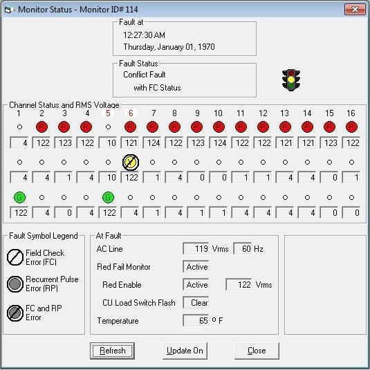
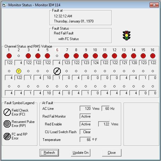
14 ECom Signal Software For use with Eberle Design brand of Conflict Monitors Display Real- Time Status Why guess when you can know? Real time status shows all signal states, field terminal voltages, and cabinet control voltages. Current fault type and fault status is displayed with time and date stamp. Channels involved in the fault are directly indicated. View a display that graphically displays signal On/Off states as well as the RMS voltage at each field terminal and at the AC Line input. It is like having a 48+ channel digital voltmeter connected to the cabinet 24 hours a day, 365 days a year. When a fault is detected the realtime status is latched as a snap-shot of the cabinet status at the time the fault was detected. The fault type is displayed with the time and date of the event. Channels involved with the fault are also directly identified.

15 MMU acts like 48 individual Volt meters on every signal output

16 Phases Normal Operation
17
18

19 Where do Signal Technicians receive training? New Jersey Section of the IMSA Passed down training within the Department Local Signal Suppliers
20 Troubleshooting Tips Always remember, in a TS 2 facility, the CU and the MMU share responsibility in looking for problems, and either may initiate a flash condition if one is detected. The following three steps will usually provide enough information to diagnose most problems in a previously working facility Look at the Alarms log Look at the MMU fault log Look at the Ring Status for Rings 1 & 2 If you are physically at the facility, the indicator LEDS on the MMU and BIUs frequently provide convenient information. The CU exerts control over the MMU using the CVM line (Controller Fault Monitor Output). Therefore, the MMU will usually not latch into a fault state for a serious problems first detected by the CU.
21 Troubleshooting Tips Example CU Screens STOPTIME Ring status Ring 1 and Ring 2 RING 1 RING 2 PHS YEL 4 YEL 4 O/N.O...O..... GAP OUT GAP OUT VEH CCCCCCCC... PED RRRRRRRR... H/O... OOOOOOOO LOCK OUT - MAX OUT MAX OUT STOPTIME 1/2 If the facility is in relay flash, but the load switch LEDs are lit and not flashing, then the MMU has most likely detected a problem before the CU and is holding the CU in stop time. The MMU may, or may not, be latched at this point, depending on what the problem was. The CU logs should have information about the nature of the problem.

22 Troubleshooting Tips Example CU Screens TS 2 DIAG FLSH NO XIT Ring status Ring 1 and Ring 2 EPAC RING TIMERS SEQ: 00 F-PRIOR MENU RING 1 RING 2 PHS MGRN 11 MGRN 11 O/N...O...O... WALK 3 WALK 3 VEH CCCCCCC.... PED RRR.RRR.... H/O... OOOOOOOO PASS 4 PASS 2 TS2 DIAG FLSH - NO XIT MAX1 31 MAX1 31 The controller has detected either a nonrecoverable TS 2 error, or has had three occurrences of a fault for an individual T&F BIU. This will require a CU reset either by power cycling, or using the 3, 5, 9 screen. The MMU may, or may not, be latched, depending on the specific problem.
23 Troubleshooting Tips Example CU Screens BIU T&F cable disconnected EPAC SYSTEM - LOCAL ALARMS REPORT MM/DD HH:MM STATUS / 1 15: 3 FRAME 138 FAULT A-PRV B-NXT WINDOW C-CLEAR F-PRIOR MENU Frame 138 is associated with T&F BIU #1, so checking the BIU would be the first reasonable troubleshooting step.
24 Troubleshooting Tips Example CU Screens CU SDLC cable disconnected Cable disconnected from CU EPAC SYSTEM - LOCAL ALARMS REPORT MM/DD HH:MM STATUS / 1 15:12 FRAME 139 FAULT 4/ 1 15:12 FRAME 128 FAULT 4/ 1 15:12 DIAG: RESP FRAME FAIL 4/ 1 15:12 FRAME 129 FAULT 4/ 1 15:12 DIAG: RESP FRAME FAIL 4/ 1 15:12 FRAME 138 FAULT 4/ 1 15:12 FRAME 148 FAULT 4/ 1 15:12 FRAME 149 FAULT 4/ 1 15:12 FRAME 150 FAULT 4/ 1 15:12 FRAME 151 FAULT 4/ 1 15:12 FRAME 131 FAULT 4/ 1 15:12 DIAG: RESP FRAME FAIL 4/ 1 15:12 FRAME 152 FAULT 4/ 1 15:12 FRAME 153 FAULT A-PRV B-NXT WINDOW C-CLEAR F-PRIOR MENU A failure of this magnitude usually indicates an electrical problem with the SDLC bus, or a problem with the CU itself.

25 The New Tool for the Signal Technician
26 Managed Network Switch

27 Traffic Adaptive Signals require knowledge of how to operate a computer and some advanced computer skills


28 Future for the Signal Tech

29 Complex signal repair
30 The End
How to Set up a TS2 Type 1 Cabinet
 2015 How to Set up a TS2 Type 1 Cabinet TS2 Set-up cheat sheet Clues for diagnosing malfuctions March 17, 2015 TS2 Type 1 Cabinet Tech Tip Sheets The following is a compendium of items that will help to
Copyright EDI
 MMU2-16LE SmartMonitor Advanced Signal Monitor Overview Eberle Design Inc. Copyright EDI 2013 050813 Managing Cabinet Malfunctions The signal monitor has three basic important tasks to perform: Detect
Copyright EDI MMU2-16LE SmartMonitor Malfunction Management Unit - Training Seminar -
 1 043013 Copyright EDI 2013 MMU2-16LE SmartMonitor Malfunction Management Unit - Training Seminar - Table of Contents Understanding Voltage Root Mean Squared MMU Training FYA (Flashing Yellow Arrow) Training
MMU-16LE Series SmartMonitor
 MMU-16LE Series SmartMonitor NEMA TS-2 Enhanced Malfunction Management Unit THIS MANUAL CONTAINS TECHNICAL INFORMATION FOR THE MMU-16LE and MMU16LEip SmartMonitor SERIES MALFUNCTION MANAGEMENT UNIT. REVISION:
MMU-16E. NEMA TS-2 Malfunction Management Unit Operations Manual
 MMU-16E NEMA TS-2 Malfunction Management Unit THIS MANUAL CONTAINS TECHNICAL INFORMATION FOR THE MMU-16E SERIES MALFUNCTION MANAGEMENT UNIT. INCLUDED ARE GENERAL DESCRIPTION, OPERATIONAL DESCRIPTION, INSTALLATION,
Eagle 2070 Reference Manual Sepac Controller Software TACTICS Software
 Eagle 7 Reference Manual Sepac Controller Software TACTICS Software O:\TRAFFIC\SIGNALS\Training\Eagle 7 - SEPAC - TACTICS Steps to follow for new 7 controllers out of the box. Access Code From the main
Naztec Version 50 Software TS-1, TS-2, 170E, 2070N. Training Unit 1 Basic Features
 NAZTEC.now Naztec Version 50 Software TS-1, TS-2, 170E, 2070N Training Unit 1 Basic Features HARDWARE FEATURES Meets or exceeds NEMA TS-1 and TS-2 specifications Socket mounted IC's for easy servicing
NEMA TS2 Standards. Standardization & Multiple Sourcing. Enhanced Safety & Reduced Liability. The Intelligent Cabinet
 NEMA TS2 Standards The Intelligent Cabinet Standardization & Multiple Sourcing TS2 specifies controllers and cabinets more fully than the TS1 or 170/179 standards by covering auxiliary functions such as
TOWN OF MANCHESTER GENERAL SERVICES DEPARTMENT 494 MAIN STREET P.O. BOX 191 MANCHESTER, CONNECTICUT
 TOWN OF MANCHESTER GENERAL SERVICES DEPARTMENT 494 MAIN STREET P.O. BOX 191 MANCHESTER, CONNECTICUT 06045-0191 TRAFFIC SIGNAL INSTALLATIONS MIDDLE TURNPIKE EAST AT SUMMIT STREET MIDDLE TURNPIKE EAST AT
NSM-E Series. NEMA TS-1 Enhanced Signal Monitor Operations Manual
 NSM-E Series NEMA TS-1 Enhanced Signal Monitor THIS MANUAL CONTAINS TECHNICAL INFORMATION FOR THE NSM-6E and NSM-12E SERIES SIGNAL MONITOR. REVISION: MARCH 2012 pn 888-1206-002 THE NSM-E SERIES SIGNAL
Advanced Transportation Controller Cabinet (ATCC) Component Overview
 Component Overview") Advanced Transportation Controller Cabinet (ATCC) Component Overview 081716 EDI Background Material This ATCC Component webinar assumes a basic knowledge of the ATC Cabinet architecture and features. Links
Advanced Transportation Controller Cabinet (ATCC) Component Overview 081716 EDI Background Material This ATCC Component webinar assumes a basic knowledge of the ATC Cabinet architecture and features. Links
Model MMU-516L-E. TS2 MMU RS232 and Ethernet (Malfunction Management Unit)
") Naztec Operations Manual For Model MMU-516L-E TS2 MMU RS232 and Ethernet (Malfunction Management Unit) Published by Naztec, Inc. 820 Park Two Dr. Sugar Land, Texas 77478 Phone: (281) 240-7233 Fax: (281)
Naztec Operations Manual For Model MMU-516L-E TS2 MMU RS232 and Ethernet (Malfunction Management Unit) Published by Naztec, Inc. 820 Park Two Dr. Sugar Land, Texas 77478 Phone: (281) 240-7233 Fax: (281)
TS2 Virtual Cabinet Model TVC-3500
 TS2 Virtual Cabinet Model TVC-3500 User's Manual Revision 1.0 Table of Contents Table of Contents 1. Explanation of Symbols and Terms...2 2. Introduction to TS2 Virtual Cabinet...3 3. Installing TS2 Virtual
SEPAC ECOM All Data. Access Code: Address: 1 1 :1200 Baud Revision: 3.34g. IP Address: :1200 Baud. 7 1-Inact. 8 1-Inact.
 Intersection Name: Central & nd SEPAC ECOM All Data Intersection Alias: Cent Access Data Access Code: 9999 Channel: Address: :00 Baud Revision:.g IP Address: 0.0.. :00 Baud Initialization Data Initial
Eberle Design Inc. MMU-16LE SmartMonitor Configuration & Installation
 Eberle Design Inc. MMU-16LE SmartMonitor Configuration & Installation Overview 040313 EDI 2013 Topics Configure the SmartMonitor for Field Use Configuration Parameters Configuration Programming Methods
OPERATIONS MANUAL SSM-18LEPR CONFLICT / VOLTAGE MONITOR
 SSM-18LEPR CONFLICT / VOLTAGE MONITOR THIS MANUAL CONTAINS TECHNICAL INFORMATION FOR THE FOLLOWING SERIES OF CONFLICT/VOLTAGE MONITORS: SSM-18LEPR. INCLUDED ARE GENERAL DESCRIPTION, OPERATIONAL DESCRIPTION,
ADU-2220 & ADU Auxiliary Display Unit
 ADU-2220 & ADU Auxiliary Display Unit THIS MANUAL CONTAINS TECHNICAL INFORMATION FOR THE ADU-2220 and ADU AUXILIARY DISPLAY UNIT FIRMWARE VERSION 012x MANUAL REVISION: MAY 2016 pn 888-2220-001 ADU-2220
Tech Note 3011 NTCIP Database Guidelines Part II
 Tech Note 3011 NTCIP Database Guidelines Part II This Tech Note extends the controller operation described in Tech Note 3010 Guidelines for NTCIP Databases Part I. These enhancements are recommended for
Trouble Shooting Leveling Control Box Electric Jacks. Touch Pad LED Probable Cause Solution
 Trouble Shooting Leveling Control Box 140-1224 Electric Jacks Copyright Power Gear Issued: January 2013 #82-L0524, Rev. OA Touch Pad LED Probable Cause Solution 1. On/Off LED will not light 2. Wait LED
BIUT TS2 Bus Interface Unit Tester. User's Manual Revision 1.0
 BIUT- 820 TS2 Bus Interface Unit Tester User's Manual Revision 1.0 Table of Contents 1. Explanation of Symbols, Terms, and Abbreviations...3 2. Safety Information...5 3. Introduction...6 4. BIUT-820 Software
Model NM512. TS1 Conflict Monitor Standard 12 Channel Unit. Naztec Operations Manual. For. Published by
 Naztec Operations Manual For Model NM512 TS1 Conflict Monitor Standard 12 Channel Unit Published by Naztec, Inc. 820 Park Two Dr. Sugar Land, Texas 77478 Phone: (281) 2407233 Fax: (281) 240-7238 Copyright
High Voltage Power Supply (MMPS) - Troubleshooting Guide
 - Troubleshooting Guide") High Voltage Power Supply (MMPS) - Troubleshooting Guide LAST UPDATED: 09/19/2018 High Voltage Power Supply (MMPS) - Troubleshooting Guide Overview The High Voltage Power Supply (MMPS - MINIMILL Power
High Voltage Power Supply (MMPS) - Troubleshooting Guide LAST UPDATED: 09/19/2018 High Voltage Power Supply (MMPS) - Troubleshooting Guide Overview The High Voltage Power Supply (MMPS - MINIMILL Power
ROAD COMMISSION FOR OAKLAND COUNTY SPECIAL PROVISION FOR DIGITAL / ITS TYPE NEMA TS2 TYPE 1 CONTROLLER AND CABINET
 RCOC/TOC: DD Page 1 of 49 RCOC12T820H This special provision outlines the Road Commission for Oakland County s specifications for the traffic signal controller and cabinet. The traffic signal controller
TD-700 FLUOROMETER SERVICE MANUAL
 TD-700 FLUOROMETER SERVICE MANUAL July 1996 CONTENTS Page Section 1 INTRODUCTION 2 Section 2 PRELIMINARY CHECKS 3 Section 3 TROUBLESHOOTING GUIDE 5 A. Lamp (Fluorescent) 5 B. Lamp Heater 7 C. Fan 8 D.
Traffic Signal Controllers
 Traffic Signal Controllers Course No: C02-056 Credit: 2 PDH Jeffrey W. Buckholz, PhD, PE, PTOE Continuing Education and Development, Inc. 9 Greyridge Farm Court Stony Point, NY 10980 P: (877) 322-5800
MOBILE CONNECTOR - GEN 2 OWNER'S MANUAL
 MOBILE CONNECTOR - GEN 2 OWNER'S MANUAL UNITED STATES Contents Safety Information... 2 Save These Important Safety Instructions... 2 Warnings...2 Cautions...3 General Information... 4 Mobile Connector
ControlKeeper 4. General Information. Connecting Relay Loads. Installation Sheet. Getting Started. Power Supply Wiring. Mounting the Cabinet
 General Information ControlKeeper 4 Installation Sheet Model# CK4-120NO- Model# CK4-277NO The ControlKeeper-4 model is shipped in one package and is configured with either a 120V or a 277V transformer.
Source-Transfer Application Guide
 S&C Model 6802 Automatic Switch Control Source-Transfer Application Guide Table of Contents Section Page Section Page Introduction Qualified Persons.... 2 Read this Instruction Sheet.... 2 Retain this
MAINTENANCE MANUAL. EDACS REDUNDANT POWER SUPPLY SYSTEM 350A1441P1 and P2 POWER MODULE CHASSIS 350A1441P3, P4, AND P5 POWER MODULES TABLE OF CONTENTS
 MAINTENANCE MANUAL EDACS REDUNDANT POWER SUPPLY SYSTEM 350A1441P1 and P2 POWER MODULE CHASSIS 350A1441P3, P4, AND P5 POWER MODULES TABLE OF CONTENTS SPECIFICATIONS*... 2 INTRODUCTION... 3 DESCRIPTION...
QCPort Cover Control Trouble Shooting Guide
 QCPort Cover Control Trouble Shooting Guide Technical Document Feb. 2006 Page 1 of 14 QCPort Cover Control Description Door Defeater Address/Options Bucket Latch Breaker Actuator Hasp Lock Keypad Overlay
An Introduction to the Advanced Transportation Controller Cabinet (ATCC)
") An Introduction to the Advanced Transportation Controller Cabinet (ATCC) Intelligent Transportation Society of Arizona 010714 EDI Topics Cabinet Overview Brief Development History Design Objectives Features
An Introduction to the Advanced Transportation Controller Cabinet (ATCC) Intelligent Transportation Society of Arizona 010714 EDI Topics Cabinet Overview Brief Development History Design Objectives Features
LVDT Test Device. Product Manual (Revision B) Original Instructions. Testing and Calibration of LVDT Feedback Devices on PG Governors
 Original Instructions. Testing and Calibration of LVDT Feedback Devices on PG Governors") Product Manual 55036 (Revision B) Original Instructions Testing and Calibration of LVDT Feedback Devices on PG Governors Operation Manual DEFINITIONS This is the safety alert symbol. It is used to alert
Product Manual 55036 (Revision B) Original Instructions Testing and Calibration of LVDT Feedback Devices on PG Governors Operation Manual DEFINITIONS This is the safety alert symbol. It is used to alert
Vector Drive - Troubleshooting Guide
 Haas Technical Documentation Vector Drive - Troubleshooting Guide Scan code to get the latest version of this document Translation Available The Haas Vector drive is the source of power for the spindle
New York City s Advanced Traffic Controller Procurement Project (ASTC)
") New York City s Advanced Traffic Controller Procurement Project (ASTC) Session August 6, 2002 Bob Rausch robert.rausch@transcore.com 1 Outline Background and history of the project Approach to the use
New York City s Advanced Traffic Controller Procurement Project (ASTC) Session August 6, 2002 Bob Rausch robert.rausch@transcore.com 1 Outline Background and history of the project Approach to the use
Energy Management System. Operation and Installation Manual
 Energy Management System Operation and Installation Manual AA Portable Power Corp 825 S 19 TH Street, Richmond, CA 94804 www.batteryspace.com Table of Contents 1 Introduction 3 2. Packing List 5 3. Specifications
PEM Faults and Blower Failures
 CHAPTER 2 The following sections provide methods for troubleshooting faults involving the Cisco 10000 series router Power Entry Modules (PEMs) and blower modules. This chapter contains the following major
Understanding the Tables To properly select a table, identify the state of the cabinet s switches then reference the corresponding table.
 General Overview The following document is designed to help ATC cabinet users interpret switches and component indicators by providing an outline for switch and component status under the following conditions:
NEMA Standards Publication TS Traffic Controller Assemblies with NTCIP Requirements Version 03.07
 NEMA Standards Publication TS 2-2016 Traffic Controller Assemblies with NTCIP Requirements Version 03.07 Published by: National Electrical Manufacturers Association 1300 North 17 th Street, Suite 900 Rosslyn,
COMMONLY USED 5.AFETY SENSORS. Photocell (Reflector) CLOSING Direction. Photocell (Reflector) CLOSING Direction OA4RO E.3IC-RIOIC4 EA4X IRB-RET
 CLOSING Direction. Photocell (Reflector) CLOSING Direction OA4RO E.3IC-RIOIC4 EA4X IRB-RET") MLY USED 5.AFETY SENSORS 0----- OA4RO E.IC-RIOIC4 Direction. Set switch to "LIGHT ". Wire V power to photocell. Wire to photocell N0 Wire to photocell C- 4. Align photocell to reflector 5. Adjust sensitivity
MLY USED 5.AFETY SENSORS 0----- OA4RO E.IC-RIOIC4 Direction. Set switch to "LIGHT ". Wire V power to photocell. Wire to photocell N0 Wire to photocell C- 4. Align photocell to reflector 5. Adjust sensitivity
P/N Rev. 01. October 7, Copyright 2005 by Econolite Control Products, Inc.
 P/N 00-0903-00 Rev. 0 October 7, 2005 Copyright 2005 by Econolite Control Products, Inc. Warranty Econolite Control Products, Inc. warrants, for a period as shown below, from date of shipment, all control
ATC I/O D
 Quick Contents Table of Figures... viii Preface About This Manual... 1 Chapter 1 Introduction to the ATC-1000... 5 Chapter 2 Quick Start: Getting a Unit Up and Running... 41 Chapter 3 Introduction to the
Installation and User Guide
 D5 Installation and User Guide 8-Channel DALI Controller (478) Introduction The 478 is for controlling DALI ballasts, drivers and load interface units (except for the 490 Blinds Controller). Do not connect
EZY SWITCH. SMS-8 System Monitor Installation Manual Applicable for firmware version 1.1 or above
 EZY SWITCH SMS-8 System Monitor Installation Manual Applicable for firmware version 1.1 or above Table of Contents Outputs 5 Inputs 6 COMMANDS Getting Started Setting Up Initial User 8 Adding a User 9
2.) Cabinet setup and preset data shall, as standard, be fully user programmable on a per cabinet or system wide basis.
 Cabinet setup and preset data shall, as standard, be fully user programmable on a per cabinet or system wide basis.") A21 DIMMER CABINET SPECIFICATION. GENERAL. A.) Overview. 1.) The dimmer cabinets shall be fully digital, designed specifically for architectural and entertainment lighting applications, and shall consist
A21 DIMMER CABINET SPECIFICATION. GENERAL. A.) Overview. 1.) The dimmer cabinets shall be fully digital, designed specifically for architectural and entertainment lighting applications, and shall consist
inavigator 2 Wire System Manual
 Polara inavigator 2 Wire System Manual For Use with iccu-s and iccu-c Rev. J 11/9/2017 Page 1 of 84 Contents 1. Safety Information 5 2. inavigator System Description 6 2.1 in2 Accessible Pedestrian Signal
Technical Service Bulletin IOX/DCX HPA Controller Backplane Replacement
 Technical Service Bulletin 040704 IOX/DCX HPA Controller Backplane Replacement The type 452101-01 HPA controller features a type 452125-01 backplane board, which acts a fiber optic receiver for telemetry
Manual. NanoTron Dual Timer. Installation Maintenance Repair Manual
 Manual NanoTron Dual Timer Installation Maintenance Repair Manual Advantage Controls P.O. Box 1472 Muskogee, OK 74402 Phone: 800-743-7431 Fax: 888-686-6212 www.advantagecontrols.com email: support@advantagecontrols.com
Using Command Zone Software
 Using Command Zone Software USING COMMAND ZONE SOFTWARE...1 COMMAND ZONE DIAGNOSTICS (CZD)...2 MENU BAR...3 MENUS...3 ONLINE/OFFLINE BUTTON...3 MODULE LIST AREA...4 TASKBAR...5 MODULE VIEWS...6 POWER MODULE
OPR Power Series AC to DC POWER SUPPLY SERIES WITH REMOTE MANAGEMENT AND ALARM SYSTEMS. Model Nos. OPR065-48S / OPR065-48R. Manual
 OPR Power Series AC to DC POWER SUPPLY SERIES WITH REMOTE MANAGEMENT AND ALARM SYSTEMS Model Nos. OPR065-48S / OPR065-48R Manual Revision F July 2009 Optimal Power Supplies LLC www.optimal-power.com i
RTK3 Logic Controller User Manual Revised
 RTK3 Logic Controller User Manual Revised 6-24-08 1 of 16 svn://software/hardware/rtk3/docs/rtk3_man.doc MRR 6/24/08 9:03 AM Overview The RTK3 is intended to simplify and expedite control wiring. Centroid
Technical Guide Plasma (GPH10DU Chassis) Troubleshooting Handbook
 Troubleshooting Handbook") Technical Guide Plasma (GPH10DU Chassis) Troubleshooting Handbook Model : TH-42PX75U TH-50PX75U TH-42PX77U TH-50PX77U Panasonic Services Company National Training Prepared by Panasonic Service and Technology
Technical Guide Plasma (GPH10DU Chassis) Troubleshooting Handbook Model : TH-42PX75U TH-50PX75U TH-42PX77U TH-50PX77U Panasonic Services Company National Training Prepared by Panasonic Service and Technology
EMCP 4.4 Simulator Manual. Author: Lucas Tolbert CIC Engineering 345 Center Street East Peoria, IL
 EMCP 4.4 Simulator Manual Author: Lucas Tolbert CIC Engineering 345 Center Street East Peoria, IL Date of Origin: 11/23/2010 Overview This document will detail the features and operation of the EMCP 4.4
Start Relay Circuit - Test
 Start Relay Circuit - Test System Operation Description: Use this procedure to troubleshoot any suspect problems with the circuit for the start relay. This procedure covers the following diagnostic codes:
Vector Drive - Troubleshooting Guide
 Haas Technical Documentation Vector Drive - Troubleshooting Guide Scan code to get the latest version of this document Translation Available The Haas Vector drive is the source of power for the spindle
Vector Drive - Troubleshooting Guide
 Haas Technical Documentation Vector Drive - Troubleshooting Guide Scan code to get the latest version of this document Translation Available The Haas Vector drive is the source of power for the spindle
SuperBus 2000 Phone Interface/Voice Module Installation Instructions
 SuperBus 2000 Module Installation Instructions Product summary The SuperBus 2000 (PIV) Module provides phone and voice functions for the Concord, Concord 4, and Concord Express (v4) panels. The PIV module
ASCO 920 Remote Control (RC) Switches
 Switches") Maximum reliability and excellent value ASCO 920 Remote Control (RC) Switches ASCO 920 Remote Control Switch in Type Enclosure The ASCO 920 is designed as a feeder disconnect switch for load capacities
Maximum reliability and excellent value ASCO 920 Remote Control (RC) Switches ASCO 920 Remote Control Switch in Type Enclosure The ASCO 920 is designed as a feeder disconnect switch for load capacities
STATE OF NEW JERSEY DEPARTMENT OF TRANSPORTATION TRENTON, NEW JERSEY 08625
 STATE OF NEW JERSEY DEPARTMENT OF TRANSPORTATION TRENTON, NEW JERSEY 08625 METRIC SPECIFICATIONS FOR VME BUS COMPUTER (FIELD TERMINAL VME BUS PROCESSOR ASSEMBLY) N.J. Specification No. Effective Date:
APPLICATION CONTROL GUIDELINES. IntelliROL Power Supply PN Revision Date: March 15, 2017
 APPLICATION CONTROL GUIDELINES IntelliROL Power Supply PN 1176718 Revision Date: March 15, 2017 Table of Contents List of Tables...3 TGW Safety Recommendation...4 Warnings and Safety Instructions...5 Introduction...6
Model NM512-E123. TS1 Conflict Monitor Enhanced 12 Channel Unit With LCD Display. Naztec Operations Manual. For. Published by
 Naztec Operations Manual For Model NM512-E123 TS1 Conflict Monitor Enhanced 12 Channel Unit With LCD Display Published by Naztec, Inc. 820 Park Two Dr. Sugar Land, Texas 77478 Phone: (281) 2407233 Fax:
DNP Points List and Implementation for Universal Controls
 S&C 6800 Series Automatic Switch Control DNP Points List and Implementation for Universal Controls Table of Contents Section Page Section Page DNP Points List for 6801 Universal Controls...1 6801 Status
Network Controller. Installation/Troubleshooting Instructions NK220 COM1131C
 Network Controller NK220 COM1131C Installation/Troubleshooting Instructions Part No. 70399101R4 October 2009 Table of Contents Getting Started... 2 Components of Network Controller... 2 System Overview...
RPX Series USER S MANUAL
 RPX Series USER S MANUAL INDEX 1.1 Introduction page 1 1.2 Packing page 1 1.3 Drawing page 2~16 1.4 Features page 17 1.5 Specification page 18~21 1.6 Installation & Testing page 22~23 1.7 Hot-Swap Procedures
Modicon Premium PLCs TSX CSY 84 / 85 / 164
 Modicon Premium PLCs TSX CSY 84 / 85 / 164 SERCOS Motion Control Quick reference guide Edition June 2009 Contents General Safety Advice for Users 2 Presentation of the TSX CSY 84/85/164 Modules 4 General
700 SERIES FLOAT OPERATED DUPLEX/TRIPLEX PUMP CONTROLLER INSTRUCTION MANUAL
 1 700 SERIES FLOAT OPERATED DUPLEX/TRIPLEX PUMP CONTROLLER INSTRUCTION MANUAL VISIT OUR WEBSITE SIGMACONTROLS.COM 700 SERIES FLOAT OPERATED DUPLEX/TRIPLEX PUMP MANUAL 042814 TABLE OF CONTENTS 2 INTRODUCTION
MYRIAD QLC 4-CHANNEL MONITOR/CONTROLLER INSTRUCTION MANUAL
 MYRIAD QLC 4-CHANNEL MONITOR/CONTROLLER INSTRUCTION MANUAL VISIT OUR WEBSITE SIGMACONTROLS.COM MYR QLC MANUAL 013114 2 TABLE OF CONTENTS INTRODUCTION 3 Ordering Information Specifications Features WIRING
Quick Start Guide TS A
 Quick Start Guide TS 930 125-630A DANGER HAZARD OF ELECTRICAL SHOCK, EXPLOSION, OR ARC FLASH Read and understand this quick start guide before installing and operating the transfer switch The installer
NEMA TS2-Type 1, P Cabinet Assembly City of San Jose Specification Rev date. November 20, 2015
 NEMA TS2-Type 1, P Cabinet Assembly City of San Jose Specification Rev date. November 20, 2015 Page 1 of 13 City of San Jose P TS2-1 Cabinet Specification A. Cabinet Minimum General Requirements The cabinet
MCU-9201MT22 venetian blind controller
 MCU-9201MT22 venetian blind controller It is strongly recommended to read and follow the instructions in this manual carefully, before you start installing or programming a system. Installation, configuration
PLT. Breaker-based transfer switch open, closed or soft transition amps. Specification sheet
 Specification sheet PLT Breaker-based transfer switch open, closed or soft transition 800 3000 amps Description PLT breaker-based transfer switches are designed for operation and switching of electrical
ROAD COMMISSION FOR OAKLAND COUNTY SPECIAL PROVISION FOR. SOLID STATE ACTUATED CONTROLLER AND CABINET January 2007 Page 1 of 38
 a. General Description ROAD COMMISSION FOR OAKLAND COUNTY Page 1 of 38 TRAFFIC SIGNAL CONTROLLER (SCATS Compatible) This specification describes an advanced traffic signal controller meeting the latest
inavigator 2 Wire System Manual
 Polara For Use with iccu-s and iccu-c Rev. N 8/23/2018 Page 1 of 87 Contents 1. Safety Information 5 2. inavigator System Description 6 2.1 in2 Accessible Pedestrian Signal Push Button Station (PBS) 6
Basketball Shot Clock Set LX2180 Manual
 Basketball Shot Clock Set LX2180 Manual 72 Industrial Boulevard Wrightsville, GA 31096 Phone: (800) 445-7843 Fax: (800) 864-0212 www.electro-mech.com LX2180 Revision 5 February 8, 2013 Table of Contents
Builder Introduction and Usage Series. Diamond Logic
 A N AV I S TA R C O M PA N Y Diamond Logic Builder Introduction and Usage Series Study Guide TMT-080703 Study Guide Diamond Logic Builder Introduction and Usage Series TMT-080703 2007 International Truck
Basics of Industrial Electricity and Troubleshooting Electrical Control Circuits
 Basics of Industrial Electricity and Troubleshooting Electrical Control Circuits Course Details Date: January 28 January 31, 2019 Time: 8:00 A.M. - 4:30 P.M. Capacity: 12 attendees Provider: National Technology
LIST OF APPENDICES APPENDIX A: DRAWING NO. TTD R2 - COMMUNICATION TERMINAL BLOCK COMPARTMENT APPENDIX B: CONTROLLER PROGRAMMING SHEET
 TABLE OF CONTENTS 1. SCOPE...1 2. REFERENCES...1 3. GENERAL TECHNICAL REQUIREMENTS...2 4. ADDITIONAL REQUIREMENTS FOR TS2, TYPE 1 TRAFFIC SIGNALS CONTROL UNIT...6 5. ADDITIONAL TECHNICAL REQUIREMENTS FOR
Models 120LS, 200LS, 300LS, 400LS, 560LS Installation Instructions
 299-600-96 Rev. F MCG Surge Protection Models 120LS, 200LS, 300LS, 400LS, 560LS Installation Instructions Important Warranty Information: MCG surge protectors are designed to work at specific voltages
SOFTWARE VERSION 3.10
 738PEP-03 SOFTWARE VERSION 3.10 HEXA PROGRAMMING: Addresses 000 to 043 and 300 to 527 are programmed using the Hexa Programming method. In this mode, you can enter any hexa-digit from 0-F where keys [1]
Nature Power Inverters. Modified Sinewave 1000w/1500w True Sinewave 1000w/2000w. Owner s Manual
 Nature Power Inverters Modified Sinewave 1000w/1500w True Sinewave 1000w/2000w Owner s Manual Modified Sinewave Series True Sinewave Series For safe and optimum performance, the Power Inverter must be
Model HM-535 Power Supply Installation and Service Instructions
 Model HM-535 Power Supply Installation and Service Instructions 430-535 0104 2004 Heritage MedCall, Inc SENTRY INSTALLATION & SERVICE INSTRUCTIONS POWER SUPPLY UNIT Model HM-535 IMPORTANT SAFETY INSTRUCTIONS
Measure Ø-N, Ø-Ø, Ø-Gnd with voltmeter to confirm application voltage prior to installation.
 Product No. 99-600-91 Rev. B Page 1 of 8 MCG Surge Protection Model 160MXT Installation Instructions Important Warranty Information MCG surge protectors are designed to work at specific voltages and configurations,
Owner s Hardware Service Manual Frank Control Computer System
 Owner s Hardware Service Manual Frank Control Computer System Revision 0105 ABOUT THIS MANUAL This section describes the contents of this manual and how to use this manual effectively. It was designed
OPERATIONS MANUAL. n.form I/O Expander (RACK MOUNT) Document Number: Rev B
 Document Number: Rev B") OPERATIONS MANUAL n.form I/O Expander (RACK MOUNT) Document Number: 200-0009 Rev B table of contents INTRODUCTION FEATURES & CAPABILITIES 1 WIRING General I/O Configuring The System Using The System 4
OPERATIONS MANUAL n.form I/O Expander (RACK MOUNT) Document Number: 200-0009 Rev B table of contents INTRODUCTION FEATURES & CAPABILITIES 1 WIRING General I/O Configuring The System Using The System 4
3000 Series TS-2 Firmware v3.6
 3000 and 3000E Traffic Controllers 3000 Series TS-2 Firmware v3.6 Peek Traffic is pleased to announce the release of Version 3.6 of the TS-2 firmware for the 3000 Series Traffic Controllers. The primary
Diagnostics of Genie / Sauer Danfoss Joystick Controllers Deutsch type connection
 Diagnostics of Genie / Sauer Danfoss Joystick Controllers Deutsch type connection Tools needed: Multi-meter Small Screwdriver Harness Adaptor 119613 Jumper Wires w/clips Three 1.5 volt AA or AAA Batteries
Use this document to validate communication and diagnose symptoms like Unknown Battery status or Car Control not functioning.
 Overview Connected car is achieved through communication between the Visage Display Unit (VDU) and the Club Car Motor Controller and Onboard Computer (OBC). With connected car, Visage provides speed control,
STATE OF NEW JERSEY DEPARTMENT OF TRANSPORTATION TRENTON, NEW JERSEY 08625
 STATE OF NEW JERSEY DEPARTMENT OF TRANSPORTATION TRENTON, NEW JERSEY 08625 SPECIFICATIONS FOR EIGHT PHASE TRAFFIC SIGNAL CONTROLLER ASSEMBLY FOR A CLOSED LOOP SYSTEM N. J. Specification No. Effective Date:
700 SERIES TPC TRIPLEX PUMP CONTROLLER INSTRUCTION MANUAL
 1 700 SERIES TPC TRIPLEX PUMP CONTROLLER INSTRUCTION MANUAL VISIT OUR WEBSITE SIGMACONTROLS.COM 700SERIESTPCMANUAL071414 2 TABLE OF CONTENTS INTRODUCTION 3 Ordering Information Specifications Features
Solid State Relays and Timers Family
 Solid State Relays and Timers Family Vehicle Control Modules Waytek Stock No. Volt Rating Amp Rating Notes Dual Input Relay Activating either Input A or Input B sets output. 75532 12 15 Dual inputs Latching
920 Remote Control (RC) Switches
 Switches") 920 Remote Control (RC) Switches ASCO is the global leader in power switching and controls ASCO 920 PRODUCT SPECIFICATIONS SWITCH ONLY (PANELBOARD MOUNTING) 1,2,3 () DIMENSIONS, IN.(MM) WIDTH HEIGHT DEPTH
920 Remote Control (RC) Switches ASCO is the global leader in power switching and controls ASCO 920 PRODUCT SPECIFICATIONS SWITCH ONLY (PANELBOARD MOUNTING) 1,2,3 () DIMENSIONS, IN.(MM) WIDTH HEIGHT DEPTH
Owner s Manual Revision 4.01 Option 1
 Owner s Manual Revision 4.01 Option 1 Special Version of the SW series Inverter / Charger for Motor Coach Applications Part # 2031-7 (Supplement to Normal Manual) Effective Date: April 17, 1996 Trace Engineering
RTK4 Logic Controller User Manual For RTK4L Revision Revised
 RTK4 Logic Controller User Manual For RTK4L Revision 120326 Revised 6-20-12 RTK4 Features Application: PLC and Third Party Drive Interface Number of Axis Drive Interfaces: 5 Axis DAC Resolution: 16 bits
inavigator 2 Wire System Manual
 Polara inavigator 2 Wire System Manual For Use with iccu-s and iccu-c Rev. P 11/20/2018 Page 1 of 96 Contents 1. Safety Information 6 2. inavigator System Description 7 2.1 in2 Accessible Pedestrian Signal
DNP Points List and Implementation
 S&C 6800 Series Automatic Switch Control DNP Points List and Implementation Table of Contents Section Page Section Page DNP Points List for 6801 Controls...1 6801 Status Points...2 6801 Double-bit Status
Cerberus Division. Installation Instructions CERBERUS PYROTRONICS TM Model RDM-MXL. (Remote Diagnostics Module)
") Cerberus Division Installation Instructions CERBERUS PYROTRONICS TM Model RDM-MXL Remote Diagnostics Module INTRODUCTION The CERBERUS PYROTRONICS TM Model RDM-MXL module (RDM for connection to the MXL
Cerberus Division Installation Instructions CERBERUS PYROTRONICS TM Model RDM-MXL Remote Diagnostics Module INTRODUCTION The CERBERUS PYROTRONICS TM Model RDM-MXL module (RDM for connection to the MXL
Broadband CTSP-EM48 Series. Total System Power Electronics Module. User Manual
 Broadband CTSP-EM48 Series Total System Power Electronics Module User Manual 990-5500F 05/2005 Chapter 1 General Information The CTSP Electronics Module (CTSP-EM) is compatible with all CTSP Transformer
First of all, thank you for purchasing R2W series redundant power supply.
 1.1 INTRODUCTION First of all, thank you for purchasing R2W series redundant power supply. The R2W series is a 1+1 hot-swappable / hot-pluggable redundant power supply. It consists of, 1) complete metal
An Overview of ATC CABINETS. Scott Evans CHIEF TECHNOLOGY OFFICER EBERLE DESIGN, INC.
 An Overview of ATC CABINETS Scott Evans CHIEF TECHNOLOGY OFFICER EBERLE DESIGN, INC. February 26, 2015 AGENDA Introduction ATC Cabinet Overview Brief Development Overview Features and Benefits Assemblies
Operating Instructions. For. Level Control Module. Model SSR 1000
 Operating Instructions For Level Control Module Model SSR 1000 SSR Operation Instructions Rev. 1 Jan 01 Page 1/7 1. Note Please read and take note of these operating instructions before unpacking and commissioning.
Remote Microprocessor Control Panel. for use with the. Redi-Purge. High Efficiency Purge System
 REDI CONTROLS, INC. Installation, Operation & Maintenance Manual Literature 1033-03 Remote Microprocessor Control Panel for use with the Redi-Purge High Efficiency Purge System MODELS PRG-11/123-C3 & PRG-113-C3