Getting Started Guide. Commander SK. Model sizes 2 to 6. AC variable speed drive for 3 phase induction motors. Issue: 7
|
|
|
- Jody Reeves
- 6 years ago
- Views:
Transcription


1 Getting Started Guide Commander SK Model sizes 2 to 6 AC variable speed drive for 3 phase induction motors Issue: 7
2 General Information The manufacturer accepts no liability for any consequences resulting from inappropriate, negligent or incorrect installation or adjustment of the optional operating parameters of the equipment or from mismatching the variable speed drive with the motor. The contents of this guide are believed to be correct at the time of printing. In the interests of a commitment to a policy of continuous development and improvement, the manufacturer reserves the right to change the specification of the product or its performance, or the contents of the guide, without notice. All rights reserved. No parts of this guide may be reproduced or transmitted in any form or by any means, electrical or mechanical including photocopying, recording or by an information storage or retrieval system, without permission in writing from the publisher. Drive software version This product is supplied with the latest software version. If this drive is to be connected to an existing system or machine, all drive software versions should be verified to confirm the same functionality as drives of the same model already present. This may also apply to drives returned from a EPA Service Centre or Repair Centre. If there is any doubt please contact the supplier of the product. The software version of the drive can be checked by looking at Pr and Pr This takes the form of xx.yy.zz where Pr displays xx.yy and Pr displays zz. (e.g. for software version , Pr = 1.01 and Pr displays 0). Environmental statement EPA is committed to minimising the environmental impacts of its manufacturing operations and of its products throughout their life cycle. To this end, we operate an Environmental Management System (EMS) which is certified to the International Standard ISO Further information on the EMS, our Environmental Policy and other relevant information is available on request, or can be found at The electronic variable-speed drives manufactured by EPA have the potential to save energy and (through increased machine/process efficiency) reduce raw material consumption and scrap throughout their long working lifetime. In typical applications, these positive environmental effects far outweigh the negative impacts of product manufacture and end-of-life disposal. Nevertheless, when the products eventually reach the end of their useful life, they must not be discarded but should instead be recycled by a specialist recycler of electronic equipment. Recyclers will find the products easy to dismantle into their major component parts for efficient recycling. Many parts snap together and can be separated without the use of tools, whilst other parts are secured with conventional fasteners. Virtually all parts of the product are suitable for recycling. Product packaging is of good quality and can be re-used. Large products are packed in wooden crates, while smaller products come in strong cardboard cartons which themselves have a high recycled fibre content. If not re-used, these containers can be recycled. Polythene, used on the protective film and bags for wrapping product, can be recycled in the same way. EPAs' packaging strategy prefers easily-recyclable materials of low environmental impact, and regular reviews identify opportunities for improvement. When preparing to recycle or dispose of any product or packaging, please observe local legislation and best practice. REACH legislation EC Regulation 1907/2006 on the Registration, Evaluation, Authorisation and restriction of Chemicals (REACH) requires the supplier of an article to inform the recipient if it contains more than a specified proportion of any substance which is considered by the European Chemicals Agency (ECHA) to be a Substance of Very High Concern (SVHC) and is therefore listed by them as a candidate for compulsory authorisation. For current information on how this requirement applies in relation to specific EPA products, please approach your usual contact in the first instance. EPA position statement can be viewed at: Issue Number:7 Software: onwards
3 Contents 1 Safety Information Product Information Ratings Typical short term overload limits Rating Data Accessories supplied with the drive Mechanical Installation Removing the terminal covers Mounting methods Mounting brackets Enclosure Electrical terminals Electrical Installation Power connections Heatsink fan Ground leakage EMC (Electromagnetic compatibility) Control terminals I/O specification Keypad and Display Programming keys Control keys Selecting and changing parameters Saving parameters Parameter access Security codes Setting drive back to default values Parameters Parameter descriptions - Level Parameter descriptions - Level Parameter descriptions - Level Diagnostic parameters Quick start commissioning Terminal control Keypad control Diagnostics Options UL listing information Common UL information Power dependant UL information AC supply specification Maximum continuous output current Safety label...78 Commander SK Size 2 to 6 Getting Started Guide Issue Number: 7
4 EPA Declaration of Conformity SK2201 SK2202 SK2203 SK2401 SK2402 SK2403 SK2404 SK3201 SK3202 SK3401 SK3402 SK3403 SK3501 SK3502 SK3503 SK3504 SK3505 SK3506 SK3507 SK4201 SK4202 SK4203 SK4401 SK4402 SK4403 SK4601 SK4602 SK4603 SK4604 SK4605 SK4606 SK5401 SK5402 SK5601 SK5602 SK6401 SK6402 SK6601 SK6602 The AC variable speed drive products listed above have been designed and manufactured in accordance with the following European harmonized standards: EN :2007 EN :2004 EN :2005 EN :2007* EN : ** EN :2008** Adjustable speed electrical power drive systems - safety requirements - electrical, thermal and energy Adjustable speed electrical power drive systems. EMC product standard including specific test methods Electromagnetic compatibility (EMC). Generic standards. Immunity standard for industrial environments Electromagnetic compatibility (EMC). Generic standards. Emission standard for industrial environments Electromagnetic compatibility (EMC). Limits. Limits for harmonic current emissions (equipment input current up to and including 16 A per phase) Electromagnetic compatibility (EMC). Limits. Limitation of voltage fluctuations and flicker in low-voltage supply systems for equipment with rated current <= 16 A * Applicable to sizes 2 to 4 only. ** Applicable to size 2 only. 1 These products are for professional use, and power input exceeds 1kW for all models, so no limits apply. These products comply with the Low Voltage Directive 2006/95/EC and the Electromagnetic Compatibility Directive 2004/108/EC. T. Alexander Executive VP Technology Date: 26th May 2009 These electronic drive products are intended to be used with appropriate motors, controllers, electrical protection components and other equipment to form complete end products or systems. Compliance with safety and EMC regulations depends upon installing and configuring drives correctly, including using the specified input filters. The drives must be installed only by professional assemblers who are familiar with requirements for safety and EMC. The assembler is responsible for ensuring that the end product or system complies with all the relevant laws in the country where it is to be used. Refer to the Technical Data Guide. An EMC Data Sheet is also available giving detailed EMC information. 4 Commander SK Size 2 to 6 Getting Started Guide Issue Number: 7

5
6 1.4 Environmental limits Instructions within the supplied data and information within the Commander SK Technical Data Guide regarding transport, storage, installation and the use of the drive must be complied with, including the specified environmental limits. Drives must not be subjected to excessive physical force. 1.5 Access Access must be restricted to authorized personnel only. Safety regulations which apply at the place of use must be complied with. The IP (Ingress Protection) rating of the drive is installation dependant. For further information, refer to the Commander SK Technical Data Guide. 1.6 Fire protection The drive enclosure is not classified as a fire enclosure. A separate fire enclosure must be provided. 1.7 Compliance with regulations The installer is responsible for complying with all relevant regulations, such as national wiring regulations, accident prevention regulations and electromagnetic compatibility (EMC) regulations. Particular attention must be given to the cross-sectional areas of conductors, the selection of fuses and other protection, and protective ground (earth) connections. The Commander SK Technical Data Guide contains instructions for achieving compliance with specific EMC standards. Within the European Union, all machinery in which this product is used must comply with the following directives: 2006/42/EC: Safety of machinery 2004/108/EC: Electromagnetic compatibility 1.8 Motor Ensure the motor is installed in accordance with the manufacturer's recommendations. Ensure the motor shaft is not exposed. Standard squirrel cage induction motors are designed for single speed operation. If it is intended to use the capability of a drive to run a motor at speeds above its designed maximum, it is strongly recommended that the manufacturer is consulted first. Low speeds may cause the motor to overheat because the cooling fan becomes less effective. The motor should be installed with a protection thermistor. If necessary, an electric force vent fan should be used. The values of the motor parameters set in the drive affect the protection of the motor. The default values in the drive should not be relied upon. It is essential that the correct value is entered into parameter 06, motor rated current. This affects the thermal protection of the motor. 1.9 Adjusting parameters Some parameters have a profound effect on the operation of the drive. They must not be altered without careful consideration of the impact on the controlled system. Measures must be taken to prevent unwanted changes due to error or tampering. 6 Commander SK Size 2 to 6 Getting Started Guide Issue Number: 7
7 1.10 Electrical installation Electric shock risk The voltages present in the following locations can cause severe electric shock and may be lethal: AC supply cables and connections DC bus, dynamic brake cables and connections Output cables and connections Many internal parts of the drive, and external option units Unless otherwise indicated, control terminals are single insulated and must not be touched Isolation device The AC supply must be disconnected from the drive using an approved isolation device before any cover is removed from the drive or before any servicing work is performed STOP function The STOP function does not remove dangerous voltages from the drive, the motor or any external option units Stored charge The drive contains capacitors that remain charged to a potentially lethal voltage after the AC supply has been disconnected. If the drive has been energized, the AC supply must be isolated at least ten minutes before work may continue. Normally, the capacitors are discharged by an internal resistor. Under certain, unusual fault conditions, it is possible that the capacitors may fail to discharge, or be prevented from being discharged by a voltage applied to the output terminals. If the drive has failed in a manner that causes the display to go blank immediately, it is possible the capacitors will not be discharged. In this case, consult EPA or their authorized distributor Equipment supplied by plug and socket Special attention must be given if the drive is installed in equipment which is connected to the AC supply by a plug and socket. The AC supply terminals of the drive are connected to the internal capacitors through rectifier diodes which are not intended to give safety isolation. If the plug terminals can be touched when the plug is disconnected from the socket, a means of automatically isolating the plug from the drive must be used (e.g. a latching relay) Ground leakage current The drive is supplied with an internal EMC filter capacitor installed. If the input voltage to the drive is supplied through an ELCB or RCD, these may trip due to the ground leakage current. See section Internal EMC filter on page 38 for further information and how to disconnect the internal EMC capacitor Mechanical installation Lifting the drive The weights of the model sizes 4, 5 and 6 are as follows: Size 4: 30kg (66Ibs) Size 5: 55kg (121Ibs) Size 6: 75kg (165Ibs) Use appropriate safeguards when lifting these models. Safety Information Product Information Mechanical Installation Electrical Installation Keypad and Display Parameters Quick start commissioning Diagnostics Options UL listing information Commander SK Size 2 to 6 Getting Started Guide 7 Issue Number: 7
8 2 Product Information 2.1 Ratings Commander SK sizes 2 to 6 are dual rated. The setting of the motor rated current determines which rating applies - Heavy Duty or Normal Duty. The two ratings are compatible with motors designed to IEC The following graph illustrates the difference between Normal Duty and Heavy Duty with respect to continuous current rating and short term overload limits. Maximum continuous current (above 50% base speed) - Normal Duty Maximum continuous current - Heavy Duty Available output current Overload limit - Heavy Duty Overload limit - Normal Duty Normal Duty For applications which use self ventilated induction motors and require a low overload capability (e.g. fans, pumps). Self ventilated induction motors require increased protection against overload due to the reduced cooling effect of the fan at low speed. To provide the correct level of protection the I 2 t software operates at a level which is speed dependent. This is illustrated in the graph below. NOTE The speed at which the low speed protection takes effect can be changed by the setting of Pr The protection starts when the motor speed is below 15% of base speed when Pr 4.25 = 0 (default) and below 50% when Pr 4.25 = 1. See Menu 4 in the Commander SK Advanced User Guide for further details. Heavy Duty (default) Heavy Duty - with high overload capability Normal Duty Motor rated current set in the drive For constant torque applications or applications which require a high overload capability (e.g. cranes, hoists). The thermal protection is set to protect force ventilated induction motors by default. NOTE If the application uses a self ventilated motor and increased thermal protection is required for speeds below 50% base speed, then this can be enabled by setting Pr 4.25 = 1. See Menu 4 in the Commander SK Advanced User Guide for further details. 8 Commander SK Size 2 to 6 Getting Started Guide Issue Number: 7

9
10

11

12

13

14
15
16

17

18

19
20 Figure 3-3 Removing the finger-guard and DC terminal cover break-outs 1 All sizes Size 3 only 1 Sizes 4 to 6 only Place finger-guard on a solid flat surface and hit relevant break-outs with hammer as shown (1). Continue until all required break-outs are removed (2). Remove any sharp edges once break-outs are removed. Figure 3-4 Size 4 to 6 finger-guard grommets Single cable entry grommet Double cable entry grommet The grommets are available as a kit of four grommets under the following part numbers: Kit of four single entry grommets Kit of four double entry grommets If the break-outs are removed from the finger-guard, then the grommets are required for Commander SK size 4 to 6 to meet the IP20 standard. 20 Commander SK Size 2 to 6 Getting Started Guide Issue Number: 7

21

22

23

24
25
26
27
28

29
30

31
32

33
34
35
36
37
38

39

40
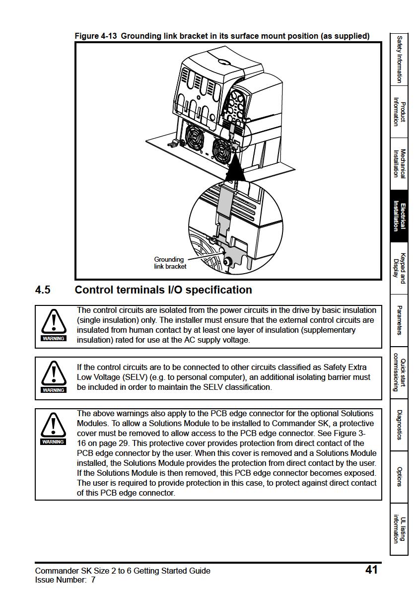
41

42

43
44
45
46
47
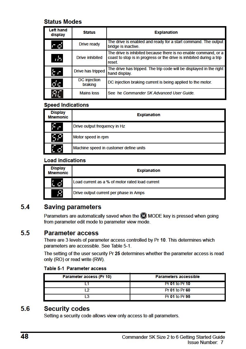
48
49
50 6 Parameters Parameters are grouped together into appropriate subsets as follows: Level 1 Pr 01 to Pr 10: Basic drive set-up parameters Level 2 Pr 11 to Pr 12: Drive operation set-up parameters Pr 15 to Pr 21: Reference parameters Pr 22 to Pr 29: Display / keypad configuration Pr 30 to Pr 33: System configuration Pr 34 to Pr 36: Drive user I/O configuration Pr 37 to Pr 42: Motor configuration (non-standard set-up) Pr 43 to Pr 44: Serial communications configuration Pr 45: Drive software version Pr 46 to Pr 51: Mechanical brake configuration Pr 52 to Pr 54: Fieldbus configuration Pr 55 to Pr 58: Drive trip log Pr 59 to Pr 60: PLC ladder programming configuration Pr 61 to Pr 70: User definable parameter area Level 3 Pr 71 to Pr 80: User definable parameter set-up Pr 81 to Pr 95: Drive diagnostics parameters These parameters can be used to optimise the set-up of the drive for the application. 6.1 Parameter descriptions - Level 1 No Function Range Defaults Type 01 Minimum set speed 0 to Pr 02 Hz 0.0 RW Used to set the minimum speed at which the motor will run in both directions. (0V reference or minimum scale current input represents the value in Pr 01). No Function Range Defaults Type 02 Maximum set speed 0 to 1500 Hz Eur: 50.0, USA: 60 0 RW Used to set the maximum speed at which the motor will run in both directions. If Pr 02 is set below Pr 01, Pr 01 will be automatically set to the value of Pr 02. (+10V reference or full scale current input represents the value in Pr 02). NOTE The output speed of the drive can exceed the value set in Pr 02 due to slip compensation and current limits. No Function Range Defaults Type 03 Acceleration rate Eur: 5.0, USA: to s/100hz RW 04 Decelera ion rate Eur: 10.0, USA: 33 0 Sets the acceleration and deceleration rate of the motor in both directions in seconds/ 100Hz. NOTE If one of the standard ramp modes is selected (see Pr 30 on page 60), the deceleration rate could be extended automatically by the drive to prevent over voltage (OV) trips if the load inertia is too high for the programmed deceleration rate. 50 Commander SK Size 2 to 6 Getting Started Guide Issue Number: 7

51
52
53
54
55
56
57 NOTE If the motor is not a standard 50 or 60Hz motor, see Pr 39 on page 63 and adjust accordingly. No Function Range Defaults Type 09 Motor power factor 0 to RW NOTE Enter the motor rated power factor cos ϕ (taken from the motor name plate). The power factor value could be automatically changed after a rotating autotune. See Pr 38 on page 63. Safety Information Product Information No Function Range Defaults Type 10 Parameter access L1, L2, L3, LoC L1 RW L1: Level 1 access - only the first 10 parameters can be accessed L2: Level 2 access - All parameters from 01 to 60 can be accessed L3: Level 3 access - All parameters from 01 to 95 can be accessed LoC: Used to lock a security code in the drive. See section 5.6 Security codes on page 48 for further details. 6.2 Parameter descriptions - Level 2 No Function Range Defaults Type 11 Start/Stop logic select 0 to 6 Eur: 0, USA: 4 RW Pr 11 Terminal B4 Terminal B5 Terminal B6 Latching 0 Enable Run Forward Run Reverse No 1 /Stop Run Forward Run Reverse Yes 2 Enable Run Forward / Reverse No 3 /Stop Run Forward / Reverse Yes 4 /Stop Run Jog Yes 5 User programmable Run Forward Run Reverse No 6 User Programmable User Programmable User Programmable User Programmable NOTE A change to Pr 11 is set by pressing the M MODE key on exit from parameter edit mode. The drive must be disabled, stopped or tripped for a change to take place. If Pr 11 is changed while the drive is running, when the M MODE key is pressed on exit from parameter edit mode, Pr 11 will change back to its previous value. No Function Range Defaults Type 12 Brake controller enable dis, rel, d IO, USEr dis RW dis: Mechanical brake software disabled rel: Mechanical brake software enabled. Brake control via relay T5 & T6. The digital output on terminal B3 is automatically programmed as a drive ok output. d IO: Mechanical brake software enabled. Brake control via digital output B3. The relay outputs on terminals T5 and T6 are automatically programmed as a drive ok output. USEr: Mechanical brake software enabled. Brake control to be programmed by user. The relay and digital output are not programmed. The user should programme the brake control to either the digital output or relay. The output not programmed to the brake control can be programmed to indicate the required signal. (See Commander SK Advanced User Guide). Mechanical Installation Electrical Installation Keypad and Display Parameters Quick start commissioning Diagnostics Options UL listing information Commander SK Size 2 to 6 Getting Started Guide 57 Issue Number: 7

58
59 No Function Range Defaults Type 18 Preset speed 1 19 Preset speed 2 ±1500 Hz (Limited by setting of Pr Preset speed 3 Maximum set speed) 0.0 RW 21 Preset speed 4 Defines preset speeds 1 to 4. No Function Range Defaults Type 22 Load display units Ld, A Ld RW Ld: Active current as a % of motor rated active current A: Drive output current per phase in Amps No Function Range Defaults Type 23 Speed display units Fr, SP, Cd Fr RW Fr: Drive output frequency in Hz SP: Motor speed in rpm Cd: Machine speed in customer defined units (See Pr 24). No Function Range Defaults Type 24 Customer defined scaling 0 to RW Multiplying factor on motor speed (rpm) to give customer defined units. No Function Range Defaults Type 25 User security code 0 to RW Used to set-up a user security code. See section 5.6 Security codes on page 48. No Function Range Defaults Type 26 Not used No Function Range Defaults Type 27 Power up keypad reference 0, LASt, PrS1 0 RW 0: keypad reference is zero LASt: keypad reference is last value selected before the drive was powered down PrS1: keypad reference is copied from preset speed 1 No Function Range Defaults Type 28 Parameter copying no, read, Prog, boot no RW no: no action read: program the drive with the contents of the SmartStick Prog: program the SmartStick with the current drive settings boot: SmartStick becomes read only. The contents of the SmartStick will be copied to the drive every time the drive is powered up. NOTE NOTE Before setting boot mode, the current drive settings must be stored in the SmartStick by using Prog mode, otherwise the drive will trip on C.Acc at power-up. Parameter copying is initiated by pressing the M MODE key on exit from parameter edit mode after Pr 28 has been set to read, Prog or boot. If parameter copying is enabled when no SmartStick is installed in the drive, the drive will trip on C.Acc. Safety Information Product Information Mechanical Installation Electrical Installation Keypad and Display Parameters Quick start commissioning Diagnostics Options UL listing information Commander SK Size 2 to 6 Getting Started Guide 59 Issue Number: 7

60

61
62 No Function Range Defaults Type 35 Digital output control (terminal B3) n=0: At zero speed At.SP: At speed Lo.SP: At minimum speed heal: Drive ok Act: Drive active ALAr: General drive alarm I.Lt: Current limit active At.Ld: At 100% load USEr: User programmable n=0, At.SP, Lo.SP, heal, Act, ALAr, I.Lt, At.Ld, USEr n=0 RW NOTE NOTE NOTE This parameter is automatically changed by the setting of Pr 12. When Pr 12 automatically controls the setting of this parameter, this parameter cannot be changed. A change to Pr 35 is set by pressing the M MODE key on exit from parameter edit mode. See the Commander SK Advanced User Guide. Terminal B3 can also be configured as a digital input, frequency output or PWM output. Refer to the Commander SK Advanced User Guide. for more information. No Function Range Defaults Type 36 Analog output control (terminal B1) Fr, Ld, A, Por, USEr Fr RW Fr: Voltage proportional to motor speed Ld: Voltage proportional to motor load A: Voltage proportional to output current Por: Voltage proportional to output power USEr: User programmable NOTE A change to Pr 36 is set by pressing the M MODE key on exit from parameter edit mode. See the Commander SK Advanced User Guide.. No Function Range Defaults Type 37 Maximum switching frequency 3, 6, 12 3 RW 3: 3kHz 6: 6kHz 12: 12kHz Drive size Voltage rating 3kHz 6kHz 12kHz 2 All SK320X 3 SK3401 & SK3402 SK3403 SK350X 4 All 5 All 6 All See the Commander SK Technical Data Guide for drive derating data. 62 Commander SK Size 2 to 6 Getting Started Guide Issue Number: 7

63
64 No Function Range Defaults Type 42 Low frequency voltage boost 0.0 to 50.0 % Eur: 3.0, USA: 1.0 RW Determines the boost level when Pr 41 is set to Fd or SrE. No Function Range Defaults Type 43 Serial communications baud rate 2.4, 4.8, 9.6, 19.2, RW 2.4: 2400 baud 4.8: 4800 baud 9.6: 9600 baud 19.2: baud 38.4: baud No Function Range Defaults Type 44 Serial comms address 0 to RW Defines the unique address for the drive for the serial interface. No Function Range Defaults Type 45 Software version 1.00 to RO Indicates the version of software installed to the drive. Pr 46 to Pr 51 appear when Pr 12 is set to control a motor brake No Function Range Defaults Type 46 Brake release current threshold 50 0 to 200 % 47 Brake apply current threshold 10 Defines the brake release and brake apply current thresholds as a % of motor current. If the frequency is >Pr 48 and the current is >Pr 46, the brake release sequence is started. If the current is <Pr 47, the brake is applied immediately. No Function Range Defaults Type 48 Brake release frequency to 20.0 Hz RW 49 Brake apply frequency 2.0 Defines the brake release and brake apply frequencies. If the current is >Pr 46 and the frequency is > Pr 48, the brake release sequence is started. If the frequency is <Pr 49 and the drive has been commanded to stop, the brake is applied immediately. No Function Range Defaults Type 50 Pre-brake release delay 0.0 to 25.0 s 1.0 RW Defines the time between the frequency and load condition being met and the brake being released. The ramp is held during this time. No Function Range Defaults Type 51 Post brake release delay 0.0 to 25 0 s 1.0 RW Defines the time between the brake being released and the ramp hold being released. RW 64 Commander SK Size 2 to 6 Getting Started Guide Issue Number: 7
65
66 No Function Range Defaults Type 54 *Solutions Module dependant 0 RW *See the Commander SK Advanced User Guide for further information. No Function Range Defaults Type 55 Last trip 56 Trip before Pr 55 0 RO 57 Trip before Pr Trip before Pr 57 Indicates the last 4 trips of the drive. No Function Range Defaults Type 59 PLC ladder program enable 0 to 2 0 RW The PLC ladder program enable is used to start and stop the PLC ladder program. 0: Stop the PLC ladder program 1: Run the PLC ladder program (trip drive if LogicStick is not installed). Any out-ofrange parameter writes attempted will be limited to the maximum/minimum values valid for that parameter before being written to. 2: Run the PLC ladder program (trip drive if LogicStick is not installed). Any out-ofrange parameter writes attempted will cause the drive to trip. See the Commander SK Advanced User Guide for details on PLC ladder programming. No Function Range Defaults Type 60 PLC ladder program status -128 to +127 RO The PLC ladder program status parameter indicates the actual state of the PLC ladder program. -n: PLC ladder program caused a drive trip due to an error condition while running rung n. Note that the rung number is shown on the display as a negative number. 0: LogicStick is installed with no PLC ladder program 1: LogicStick is installed, PLC ladder program is installed but stopped 2: LogicStick is installed, PLC ladder program is installed and running 3: LogicStick is not installed No Function Range Defaults Type 61 to Configurable parameter 1 to As source 70 configurable parameter 10 Pr 61 to Pr 70 and Pr 71 to Pr 80 can be used to access and adjust advanced parameters. Example: It is desired that Pr 1.29 (Skip frequency 1) is to be adjusted. Set one of the parameters Pr 71 to Pr 80 to 1.29, the value of Pr 1.29 will appear in the corresponding parameter from Pr 61 to Pr 70. I.e. if Pr 71 is set to 1.29, Pr 61 will contain the value of Pr 1.29 where it can be adjusted. NOTE Some parameters are only implemented if the drive is disabled, stopped or tripped and the STOP/RESET key is pressed for 1s. See Commander SK Advanced User Guide for advanced parameter details. 66 Commander SK Size 2 to 6 Getting Started Guide Issue Number: 7
67 6.3 Parameter descriptions - Level 3 No Function Range Defaults Type 71 to Pr 61 to Pr 70 set up 0 to Pr RW 80 Set Pr 71 to Pr 80 to the required advanced parameter number to be accessed. The value within these parameters will be displayed in Pr 61 to Pr 70. Pr 61 to Pr 70 can then be adjusted to change the value within a parameter. See Commander SK Advanced User Guide for further details. 6.4 Diagnostic parameters The following read only (RO) parameters can be used as an aid to fault diagnosis on the drive. See Figure 8-1 Diagnostics logic diagram on page 74. No Function Range Type 81 Frequency reference selected ±Pr 02 Hz RO 82 Pre-ramp reference ±Pr 02 Hz RO 83 Post-ramp reference ±Pr 02 Hz RO 84 DC bus voltage 0 to Drive maximum Vdc RO 85 Motor frequency ±Pr 02 Hz RO 86 Motor voltage 0 to Drive rating V RO 87 Motor speed ±9999 rpm RO 88 Motor current +Drive maximum A RO 89 Motor ac ive current ±Drive maximum A RO 90 Digital I/O read word 0 to 95 RO 91 Reference enabled indicator OFF or On RO 92 Reverse selected indicator OFF or On RO 93 Jog selected indicator OFF or On RO 94 Analog input 1 level 0 to 100 % RO 95 Analog input 2 level 0 to 100 % RO Safety Information Product Information Mechanical Installation Electrical Installation Keypad and Display Parameters Quick start commissioning Diagnostics Options UL listing information Commander SK Size 2 to 6 Getting Started Guide 67 Issue Number: 7
68
69
70
71

72
73 Trip code Condition Possible cause C.rtg SmartStick/drive ra ing change Already programmed SmartStick read by a drive of a different rating O.cL Overload on current loop input Input current exceeds 25mA HFxx trip Hardware faults Internal drive hardware fault (see Commander SK Advanced User Guide) NOTE * The Enable/Reset terminal will not reset an O.Ld1 trip. Use the Stop/Reset key. ** These trips cannot be reset for 10 seconds after they occur. See the Commander SK Advanced User Guide for further information on possible causes of drive trips. Table 8-1 DC bus voltages Drive voltage rating UV trip level UV reset level * Braking level OV trip level ** 200V V V V * These are the absolute minimum DC voltages the drives can be supplied by. ** The drive will trip on OV if the DC Bus goes above the OV trip level. Table 8-2 Alarm warnings/display indications Display Condition Solution OVL.d I x t overload (I = current, t = time) Reduce motor current (Load) hot Heatsink/IGBT temperature high Reduce ambient temperature or reduce motor current br.rs Braking resistor overload See Menu 10 in the Commander SK Advanced User Guide AC.Lt Drive is in current limit See Menu 10 in the Commander SK Advanced User Guide FAIL Failed attempt to read stick An attempt was made to read the stick when the drive was not disabled or tripped, or the stick is read only NOTE If no action is taken when an alarm warning appears, the drive will trip on the appropriate fault code. Safety Information Product Information Mechanical Installation Electrical Installation Keypad and Display Parameters Quick start commissioning Diagnostics Options UL listing information Commander SK Size 2 to 6 Getting Started Guide 73 Issue Number: 7
74

75
.")
76 Option name Function Picture CTSoft Software for PC or Laptop which allows he user to commission and store parameter settings SyPTLite Software for PC or Laptop which allows the user to program PLC functions within the drive Braking resistor Optional internal braking resistor for Commander SK size 2 (see Commander SK Technical Data Guide for further details). Details of all the above options can be found at and on the CD supplied with the drive. 76 Commander SK Size 2 to 6 Getting Started Guide Issue Number: 7
77 10 UL listing information The UL file number is E Confirmation of UL listing can be found on the UL website: Common UL information Conformity The drive conforms to UL listing requirements only when the following are observed: The drive is installed in a type 1 enclosure, or better, as defined by UL50 The ambient temperature does not exceed 40 C (104 F) when the drive is operating The terminal tightening torques specified in section Terminal sizes and torque settings on page 30. Motor overload protection The drive provides motor overload protection. The default overload protection level is no higher than 150% of full-load current (FLC) of the drive. It is necessary for the motor rated current to be entered into Pr 06 (or Pr 5.07) for the protection to operate correctly. The protection level may be adjusted below 150% if required. The drive also provides motor thermal protection, refer to Pr 4.15, Pr 4.19 and Pr 4.25 in the Commander SK Advanced User Guide. Overspeed protection The drive provides overspeed protection. However, it does not provide the level of protection afforded by an independent high integrity overspeed protection device Power dependant UL information Conformity The drive conforms to UL listing requirements only when the following is observed: Fuses Size 2 to 3 The correct UL-listed high speed/fast acting fuses (class CC or class J up to 30A and class J above 30A), e.g. Bussman Limitron KTK series, Gould Amp-Trap ATM series or equivalent, are used in the AC supply. The drive does not comply with UL if MCBs are used in place of fuses. For further details on fusing, refer to section 2.3 Rating Data on page 10. Size 4 to 6 The UL-listed Ferraz HSJ (High speed J class) fuses are used in the AC supply. The drive does not comply with UL if any other fuses or MCBs are used in place of those stated. For further details on fusing, refer to section 2.3 Rating Data on page 10. Field wiring Size 2 to 4 Class 1 60/75 C (140/167 F) copper wire only is used in the installation Size 5 and 6 Class 1 75 C (167 F) copper wire only is used in the installation Field wiring connectors Sizes 4 to 6 UL listed wire connectors are used for terminating power circuit field wiring, e.g. Ilsco TA series Safety Information Product Information Mechanical Installation Electrical Installation Keypad and Display Parameters Quick start commissioning Diagnostics Options UL listing information Commander SK Size 2 to 6 Getting Started Guide 77 Issue Number: 7
78 10.3 AC supply specification The Commander SK is suitable for use in a circuit capable of delivering not more than 100,000rms symmetrical Amperes at 264Vac rms maximum (200V drives), 528Vac rms maximum (400V drives) or 600Vac rms maximum (575V and 690V drives) Maximum continuous output current The drive models are listed as having the maximum continuous output currents (FLC) shown in Table 10-1, Table 10-2, Table 10-3 and Table 10-4 (see the Commander SK Technical Data Guide for details). Table 10-1 Maximum continuous output current (200V drives) Model FLC (A) Model FLC (A) SK SK SK SK SK SK SK SK Table 10-2 Maximum continuous output current (400V drives) Model FLC (A) Model FLC (A) SK SK SK SK SK SK SK SK SK SK SK SK SK SK Table 10-3 Maximum continuous output current (575V drives) Model FLC (A) Model FLC (A) SK SK SK SK SK SK SK Table 10-4 Maximum continuous output current (690V drives) Model FLC (A) Model FLC (A) SK SK SK SK SK SK SK SK SK SK Safety label The safety label supplied with the connectors and mounting brackets must be placed on a fixed part inside the drive enclosure where it can be seen clearly by maintenance personnel for UL compliance. The label clearly states CAUTION Risk of Electric Shock Power down unit 10 minutes before removing cover. 78 Commander SK Size 2 to 6 Getting Started Guide Issue Number: 7
79
80
6181 9704-0 Telefax +49 (0)6181 9704-99 e-mail: info@epa-antriebe.de www.epa-antriebe.de Änderungen und Irrtümer vorbehalten.")
81 Ihr Partner für elektrische Antriebe / your partner for electrical drives EP ANTRIEBSTECHNIK GmbH Fliederstraße 8 Postfach Bruchköbel Bruchköbel Telefon +49 (0) Telefax +49 (0) info@epa-antriebe.de Änderungen und Irrtümer vorbehalten. / We reserve the right to changes without further notice.
Commander SK. Getting Started Guide. AC variable speed drive for 3 phase induction motors. Model sizes 2 to 6. Part Number: Issue: 8
 Getting Started Guide Commander SK Model sizes 2 to 6 AC variable speed drive for 3 phase induction motors Part Number: 0472-0064-08 Issue: 8 www.controltechniques.com General Information The manufacturer
User Guide. Unidrive M700. Frame sizes 3 to 10. Low voltage DC operation in Elevator Applications. Issue: 1
 User Guide Low voltage DC operation in Elevator Applications Unidrive M700 Frame sizes 3 to 10 Issue: 1 Original Instructions For the purposes of compliance with the EU Machinery Directive 2006/42/EC General
Macro Guide. Affinity. Model sizes 1 to 6. Building Automation HVAC/R drive. Part Number: Issue: 1.
 Macro Guide Affinity Model sizes to Building Automation HVAC/R drive Part Number: 0-000-0 Issue: www.controltechniques.com General Information The manufacturer accepts no liability for any consequences
Commander SK. EF Getting Started Guide
 EF www.controltechniques.com Getting Started Guide Commander SK AC variable speed drive for 3 phase induction motors from 0.25kW to 4kW, 0.33hp to 5hp Model sizes A, B and C Part Number: 0472-0000-01 Issue:
Commander SK. Getting Started Guide. AC variable speed drive for 3 phase induction motors from 0.25kW to 7.5kW, 0.33hp to 10hp
 Getting Started Guide Commander SK AC variable speed drive for 3 phase induction motors from 0.25kW to 7.5kW, 0.33hp to 10hp Model sizes A, B, C and D Part Number: 0472-0000-11 Issue: 11 www.controltechniques.com
Commander SK. Getting Started Guide. AC variable speed drive for 3 phase induction motors from 0.25kW to 7.5kW, 0.33hp to 10hp
 Getting Started Guide Commander SK AC variable speed drive for 3 phase induction motors from 0.25kW to 7.5kW, 0.33hp to 10hp Model sizes A, B, C and D Part Number: 0472-0000-06 Issue: 6 www.controltechniques.com
IM-pAC. Getting Started Guide. AC variable speed drive for 3 phase induction motors from 0.25kW to 4kW, 0.33hp to 5hp. Model sizes A, B and C
 Getting Started Guide IM-pAC AC variable speed drive for 3 phase induction motors from 0.25kW to 4kW, 0.33hp to 5hp Model sizes A, B and C Part Number: 0472-0056-04 Issue: 4 General The manufacturer accepts
User Guide. Cloning interface small option module for Unidrive and Commander GP. Part Number: Issue Number: 3
 User Guide UD55 Cloning interface small option module for Unidrive and Commander GP Part Number: 0460-0095 Issue Number: 3 General Information The manufacturer accepts no liability for any consequences
Unidrive M100. User Guide. Model size 1 to 4. Variable Speed AC drive for induction motors. Part Number: Issue: 1
 User Guide Unidrive M100 Model size 1 to 4 Variable Speed AC drive for induction s Part Number: 0478-0041-01 Issue: 1 www.controltechniques.com Original Instructions For the purposes of compliance with
SM-DeviceNet. User Guide. Solutions Module for: Unidrive SP Commander SK Digitax ST Mentor MP Affinity. Part Number: Issue Number: 7
 User Guide SM-DeviceNet Solutions Module for: Unidrive SP Commander SK Digitax ST Mentor MP Affinity Part Number: 0471-0009-07 Issue Number: 7 www.controltechniques.com General Information The manufacturer
Getting Started Guide. Powerdrive F300. Frame Sizes 3 to 10. Part Number: Issue: 1.
 Getting Started Guide Powerdrive F300 Frame Sizes 3 to 10 Part Number: 0479-0002-01 Issue: 1 www.controltechniques.com Original Instructions For the purposes of compliance with the EU Machinery Directive
IM-pAC. Getting Started Guide. AC variable speed drive for 3 phase induction motors from 0.25kW to 4kW, 0.33hp to 5hp. Model sizes A, B and C
 Getting Started Guide IM-pAC AC variable speed drive for 3 phase induction motors from 0.25kW to 4kW, 0.33hp to 5hp Model sizes A, B and C Part Number: 0472-0056-05 Issue: 5 General Information The manufacturer
Getting Started Guide. Unidrive M700 Unidrive M701. Part Number: Issue: 5.
 Getting Started Guide Unidrive M700 Unidrive M701 Part Number: 0478-0001-05 Issue: 5 www.controltechniques.com For the purposes of compliance with the EC Machinery Directive 2006/42/EC: General Information
Unidrive M400. User Guide. Model size 1 to 8. Variable Speed AC drive for induction motors. Part Number: Issue: 6
 User Guide Unidrive M400 Model size to 8 Variable Speed AC drive for induction motors Part Number: 0478-0044-06 Issue: 6 www.controltechniques.com Original Instructions For the purposes of compliance with
SM-I/O Plus. Solutions module for UNIDRIVE SP. User guide. This manual is to be given to the end user. Réf en / a
 M Réf. 3952 en - 09.2005 / a T2 digital I/O 1 state T2 output select??.?? X.09 X.31 0 1 x(-1)??.?? This manual is to be given to the end user 2 T2 digital I/O 1 Positive logic select 1 0 X.29 X.11 x(-1)
User Guide SI-PROFIBUS. Part Number: Issue Number: 2.
 User Guide SI-PROFIBUS Part Number: 0478-0011-02 Issue Number: 2 www.controltechniques.com General Information The manufacturer accepts no liability for any consequences resulting from inappropriate, negligent
EF User Guide SM-I/O 120V. Solutions Module for: Unidrive SP Commander SK. Part Number: Issue Number: 2
 EF www.controltechniques.com User Guide SM-I/O 120V Solutions Module for: Unidrive SP Commander SK Part Number: 0471-0054-02 Issue Number: 2 General Information The manufacturer accepts no liability for
User Guide. SM-I/O 24V Protected. Solutions Module for: Unidrive SP Commander SK Commander GP20. Part Number: Issue: 3
 User Guide SM-I/O 24V Protected Solutions Module for: Unidrive SP Commander SK Commander GP20 Part Number: 0471-0072-03 Issue: 3 Original Instructions For the purposes of compliance with the EU Machinery
Software Statement. Copyright : July 2010 Control Techniques Ltd. Issue Number : 10
 User Guide SM-PROFIBUS DP-V1 Solutions Module for: Unidrive SP Commander SK Affinity Digitax ST Mentor MP Part Number: 0471-0008-10 Issue Number: 10 www.controltechniques.com General Information The manufacturer
Getting Started Guide. Unidrive M700 Unidrive M701. Model sizes 3 to 10. Part Number: Issue: 7.
 Getting Started Guide Unidrive M700 Unidrive M701 Model sizes 3 to 10 Part Number: 0478-0001-07 Issue: 7 www.controltechniques.com Original Instructions For the purposes of compliance with the EU Machinery
Mentor MP. Short Form Guide. High performance DC drive 25A to 7400A, 480V to 690V Two or four quadrant operation. Part Number: Issue: 4
 Short Form Guide Mentor MP High performance DC drive 25A to 7400A, 480V to 690V Two or four quadrant operation Part Number: 0476-0003-04 Issue: 4 www.controltechniques.com General Information The manufacturer
User Guide FXMP25. Field Controller. Part Number: Issue: 2.
 User Guide FXMP25 Field Controller Part Number: 0476-0009-02 Issue: 2 www.controltechniques.com General Information The manufacturer accepts no liability for any consequences resulting from inappropriate,
UNIDRIVE SP DIGIDRIVE SK DIGITAX ST MENTOR MP AFFINITY
 3935 en - 2010.02 / b UNIDRIVE SP DIGIDRIVE SK DIGITAX ST MENTOR MP AFFINITY Start Send first telegram to OUT word 0 READ Send telegram 3 to OUT word 0 Read IN word 0 This manual is to be given to the
Unidrive M200/201. User Guide. Model size 1 to 6. Variable Speed AC drive for induction motors. Part Number: Issue: 4
 User Guide Unidrive M200/20 Model size to 6 Variable Speed AC drive for induction motors Part Number: 0478-0042-04 Issue: 4 www.controltechniques.com General The manufacturer accepts no liability for any
Unidrive M400. Control Quick Start Guide
 Control Quick Start Guide Unidrive M400 Manufacturing Automation drive Fast set-up and diagnosis with real-text display, plus integrated Machine Control Studio based PLC Part Number: 0478-0267-04 Issue:
User Guide SM-I/O PELV. Solutions Module for: Unidrive SP Commander SK. Part Number: Issue: 3.
 User Guide SM-I/O PELV Solutions Module for: Unidrive SP Commander SK Part Number: 0471-0043-03 Issue: 3 www.controltechniques.com General Information The manufacturer accepts no liability for any consequences
Frame 5 to 6 Power Installation Guide
 Frame 5 to 6 Power Installation Guide Unidrive M / HS Part Number: 0478-0255-05 Issue: 5 Original Instructions For the purposes of compliance with the EU Machinery Directive 2006/42/EC. General Information
Unidrive M600. User Guide. Model size 3 to 10. Universal Variable Speed AC drive for induction and permanent magnet motors
 User Guide Unidrive M600 Model size 3 to 10 Universal Variable Speed AC drive for induction and permanent magnet motors Part Number: 0478-0004-03 Issue: 3 www.controltechniques.com Original Instructions
User Guide SM-I/O PELV. Solutions Module for: Unidrive SP Commander SK. Part Number: Issue: 4
 User Guide SM-I/O PELV Solutions Module for: Unidrive SP Commander SK Part Number: 0471-0043-04 Issue: 4 Original Instructions For the purposes of compliance with the EU Machinery Directive 2006/42/EC,
User Guide FXMP25. Field Controller. Part Number: Issue: 3.
 User Guide FXMP25 Field Controller Part Number: 0476-0009-03 Issue: 3 www.controltechniques.com General Information The manufacturer accepts no liability for any consequences resulting from inappropriate,
Control User Guide. Unidrive M100/101. Variable Speed AC drive for induction motors. Part Number: Issue: 3
 Control User Guide Unidrive M100/101 Variable Speed AC drive for induction s Part Number: 0478-0352-03 Issue: 3 Original Instructions For the purposes of compliance with the EU Machinery Directive 2006/42/EC,
User Guide SM-PROFIBUS DP-V1. Solutions Module for: Unidrive SP Commander SK Affinity Digitax ST Mentor MP. Part Number: Issue Number: 11
 User Guide SM-PROFIBUS DP-V1 Solutions Module for: Unidrive SP Commander SK Affinity Digitax ST Mentor MP Part Number: 0471-0008-11 Original Instructions For the purposes of compliance with the EU Machinery
Control User Guide. Unidrive M200/M201. Variable Speed AC drive for induction motors. Part Number: Issue: 2
 Control User Guide Unidrive M200/M201 Variable Speed AC drive for induction s Part Number: 0478-0351-02 Issue: 2 Original Instructions For the purposes of compliance with the EU Machinery Directive 2006/42/EC,
User Guide. SI-EtherCAT. Part Number: Issue Number: 1.
 User Guide SI-EtherCAT Part Number: 0478-0152-01 www.controltechniques.com General Information The manufacturer accepts no liability for any consequences resulting from inappropriate, negligent or incorrect
Unidrive M400 (Frame 1 to 4) Quick Start Guide
 Quick Start Guide") This guide is intended to provide basic information required in order to set-up a drive to run a motor. For more detailed installation information, please refer to the Unidrive M400 User Guide which is
This guide is intended to provide basic information required in order to set-up a drive to run a motor. For more detailed installation information, please refer to the Unidrive M400 User Guide which is
Operating instructions. Speed monitor D / / 2014
 Operating instructions Speed monitor D200 80005257 / 00 05 / 2014 Contents 1 Preliminary note...4 1.1 Symbols used...4 1.2 Warning signs used...4 2 Safety instructions...5 2.1 General...5 2.2 Target group...5
User Guide. VFD66 Drive. AC variable speed drive for 3 phase induction motors from 0.75kW to 2.2kW, 1hp to 3hp. Part Number: Issue: 3
 User Guide VFD66 Drive AC variable speed drive for 3 phase induction motors from 0.75kW to 2.2kW, 1hp to 3hp Part Number: 24-10511-90 Issue: 3 General Information The manufacturer accepts no liability
KBG2 Series. Control User Guide. Variable Speed AC drive for induction motors.
 Control User Guide KBG2 Series Variable Speed AC drive for induction s. For applications that require ratings higher than 30 HP (22.5 kw), contact our Sales Department. Copyright 2018 KB Electronics, Inc.
Frame 1 to 4 Power Installation Guide
 Frame 1 to 4 Power Installation Guide Unidrive M100 to M400 Part Number: 0478-0336-02 Issue: 2 Original Instructions For the purposes of compliance with the EU Machinery Directive 2006/42/EC, the English
SMVector Additional I/O Module Installation and Operation Manual
 SMVector Additional I/O Module Installation and Operation Manual About These Instructions This documentation applies to the optional Additional I/O module for the SMVector inverter and should be used in
SM-RESOLVER. Solutions module for UNIDRIVE SP. User guide. This manual is to be given to the end user
 M 3953 en - 10.2005 / a Term Resolver connections 9 SIN LOW 10 SIN HIGH 11 COS LOW 12 COS HIGH 13 REF HIGH (excitation) 14 REF LOW (excitation) 15 0V 16 0V 17 0V x.10 x.13 x.15 This manual is to be given
Unidrive M200, M201 (Frame 1 to 4) Quick Start Guide
 Quick Start Guide") This guide is intended to provide basic information required in order to set-up a drive to run a motor. Please refer to the Unidrive M200 / M20 User Guide which is available to download from www.controltechniques.com/user
This guide is intended to provide basic information required in order to set-up a drive to run a motor. Please refer to the Unidrive M200 / M20 User Guide which is available to download from www.controltechniques.com/user
ATV12H018M2 variable speed drive ATV kW hp V - 1ph
 Characteristics variable speed drive ATV12-0.18kW - 0.25hp - 200..240V - 1ph Complementary Main Range of product Altivar 12 Product or component type Product destination Product specific application Assembly
Installation, Operation and Maintenance Manual
 Document 481200 VGD-100 Vari-Green Drive Installation, Operation and Maintenance Manual Please read and save these instructions for future reference. Read carefully before attempting to assemble, install,
Operating instructions. Switching amplifier DN0210 DN / / 2015
 Operating instructions Switching amplifier DN0210 DN0220 UK 80011079 / 00 01 / 2015 Contents 1 Preliminary note...4 1.1 Symbols used...4 1.2 Warning signs used...4 2 Safety instructions...5 2.1 General...5
Control Quick Start Guide. Unidrive M200/ M201. Flexible machine integration through communications. Part Number: Issue: 4
 Control Quick Start Guide Unidrive M200/ M201 Flexible machine integration through communications Part Number: 0478-0282-04 Issue: 4 Original Instructions For the purposes of compliance with the EU Machinery
Short Form Guide. Unidrive SP. Part Number: Issue: 2.
 Short Form Guide Unidrive SP Part Number: 047-062-02 Issue: 2 www.controltechniques.com General The manufacturer accepts no liability for any consequences resulting from inappropriate, negligent or incorrect
ATV12P037F1 variable speed drive ATV kW hp V - 1ph - on base plate
 Characteristics variable speed drive ATV12-0.37kW - 0.55hp - 100..120V - 1ph - on base plate Complementary Main Range of product Altivar 12 Product or component type Product destination Product specific
Unidrive M400 Fast set-up and diagnostics with real-text display, integrated PLC and safety inputs
 Unidrive M400 Fast set-up and diagnostics with real-text display, integrated PLC and safety inputs 0.25 kw - 110 kw Heavy Duty (0.33 hp - 150 hp) 100 V 200 V 400 V 575 V 690 V Unidrive M Optimized throughput,
SM-I/O Lite and SM-I/O Timer Solutions module for DIGIDRIVE SK and UNIDRIVE SP User guide
 3949 en - 09.2005 / a Invert x.14 Monitor T5 x.04 0 1 This manual is to be given to the end user Monitor Invert x.15 T6 x.05 0 1 SM-I/O Lite and SM-I/O Timer Solutions module for DIGIDRIVE SK and UNIDRIVE
User Guide. IP20 & IP66 (NEMA 4X) AC Variable Speed Drive. Installation and Operating Instructions. 1 Quick Start Up kW (0.
 AC Variable Speed Drive. Installation and Operating Instructions. 1 Quick Start Up kW (0.") 1 Quick Start Up User Guide IP20 & IP66 (NEMA 4X) AC Variable Speed Drive 0.37 22kW (0.5 30HP) 110 480V Installation and Operating Instructions 1 Quick Start Up 1 1. Quick Start Up... 4 1.1. Important
1 Quick Start Up User Guide IP20 & IP66 (NEMA 4X) AC Variable Speed Drive 0.37 22kW (0.5 30HP) 110 480V Installation and Operating Instructions 1 Quick Start Up 1 1. Quick Start Up... 4 1.1. Important
POWERDRIVE UNIDRIVE SP VARMECA 33/34 PROXIDRIVE DIGIDRIVE IVE SK
 3934 en - 2009.03 / b POWERDRIVE UNIDRIVE SP VARMECA 33/34 PROXIDRIVE DIGIDRIVE IVE SK Start Send first telegram to OUT word 0 READ Send telegram 3 to OUT word 0 Read IN word 0 This manual is to be given
PART 1: GENERAL PART 2: PRODUCT. Effective: 12/29/10 Page 1 of 6 FECA-TE-104D
 Specification Number: 23 09 33 Product Name: FRENIC-Eco AC Drives for Variable Torque Fan & Pump Applications (1-125Hp at 208/230V and 1-900Hp at 460V) PART 1: GENERAL 1.01 SUMMARY A. This specification
Extension module for lighting control
 s 3 842 DESIGO RXC Extension module for lighting control Extension to the RXC30 / RXC31 / RXC38 room controller RXC40.1 RXC40.5 The RXC40 extension module is used in conjunction with an RXC30, RXC31 or
EF User Guide. SM-I/O Lite SM-I/O Timer. Solutions Module for: Unidrive SP Commander SK. Part Number: Issue: 4
 EF www.controltechniques.com User Guide SM-I/O Lite SM-I/O Timer Solutions Module for: Unidrive SP Commander SK Part Number: 0472-0004-04 Issue: 4 General Information The manufacturer accepts no liability
Copyright: December 2017 Nidec Issue: E
 General Information The manufacturer accepts no liability for any consequences resulting from inappropriate, negligent or incorrect installation or adjustment of the optional parameters of the equipment
Installation Guide. QBox-V6. Standalone/Spare V6 SDI QBox. Standalone/Spare V6 SDI QBox. Part No. A
 Installation Guide Standalone/Spare V6 SDI QBox QBox-V6 Standalone/Spare V6 SDI QBox Part No. A9009-0004 EN www.autocue.com Copyright 2017 All rights reserved. Original Instructions: English All rights
Specification Number: Product Name: FRENIC-Mega AC Drives for General Purpose Applications (½ - 150Hp at 230V and ½ Hp at 460V)
") Specification Number: 26 29 23 Product Name: FRENIC-Mega AC Drives for General Purpose Applications (½ - 150Hp at 230V and ½ - 1000Hp at 460V) PART 1: GENERAL 1.01 SUMMARY A. This specification provides
Specification Number: 26 29 23 Product Name: FRENIC-Mega AC Drives for General Purpose Applications (½ - 150Hp at 230V and ½ - 1000Hp at 460V) PART 1: GENERAL 1.01 SUMMARY A. This specification provides
AC Variable Speed Drive
 User Manual AC Variable Speed Drive IP66 (NEMA 4X) 0.37kW 22kW / 0.5HP 30HP 110 480V 3 Phase Input Quick Start Up General Information and Ratings Mechanical Installation Power & Control Wiring Operation
AC Variable Speed Drive
 User Manual AC Variable Speed Drive IP20 & IP66 (NEMA 4X) 0.37kW 22kW / 0.5HP 30HP 110 480V 3 Phase Input Troubleshooting 0 Quick Start Up General Information and Ratings Mechanical Installation Power
lnvertek Drives.com ct,ve ELECTRICAL SUPPLIERS LTD
 lnvertek Drives.com ft ct,ve ELECTRICAL SUPPLIERS LTD OptidriveE2 Technical Product Guide 1.1 OVERVIEW Range IP20 IP66X (NON SWITCHED) IP66Y (SWITCHED) Supply Voltage Range Power Range 110 115 + / 10%
Instruc on Manual. Series S3. Industrial Inverter IP20 IP66
 Instruc on Manual Industrial Inverter Series S3 IP20 IP66 1. Quick Start Up... 4 1.1. Important Safety Information 4 1.2. Quick Start Process 5 1.3 Installation Following a Period of Staorage 5 1.4. Quick
ATV12H075M3 variable speed drive ATV kW - 1hp V - 3ph - with heat sink
 Product datasheet Characteristics ATV12H075M3 variable speed drive ATV12-0.75kW - 1hp - 200..240V - 3ph - with heat sink Complementary Main Range of product Altivar 12 Product or component type Product
User Guide. Mentor MP. High performance DC drive 25A to 7400A, 480V to 690V Two or four quadrant operation. Part Number: Issue: 7
 User Guide Mentor MP High performance DC drive 25A to 7400A, 480V to 690V Two or four quadrant Part Number: 0476-0000-07 Original Instructions For the purposes of compliance with the EU Machinery Directive
MDM 011-Z1 Regen Resistor
 MDM 011-Z1 Regen Resistor Date of creation: 10.04.2017 Version date: 10.04.2017 Article number: 09-402-011-Z1-E Publisher: SIGMATEK GmbH & Co KG A-5112 Lamprechtshausen Tel.: 06274/4321 Fax: 06274/4321-18
Power supply module, bus connection module
 s 8 183 8183p01, p02 TX-I/O Power supply module, bus connection module TXS1.12F10 TXS1.EF10 Each I/O row begins with one of these devices TXS1.12F10 power supply module Up to 4 power supply modules can
ATV12P075M3 variable speed drive ATV kW - 1hp V - 3ph - on base plate
 Characteristics variable speed drive ATV12-0.75kW - 1hp - 200..240V - 3ph - on base plate Main Range of product Altivar 12 Product or component type Product destination Product specific application Assembly
User Guide. Dinverter 2B. Variable Speed Drive for three-phase induction motors 0.75kW to 4.0kW 1.0HP to 5.3HP. Part Number: Issue Number: 6
 User Guide Dinverter 2B Variable Speed Drive for three-phase induction motors 0.75kW to 4.0kW 1.0HP to 5.3HP Part Number: 0444-0014 Issue Number: 6 General information The manufacturer accepts no liability
Operating instructions AS-i SmartLine module AC3200 AC /00 06/2016
 Operating instructions AS-i SmartLine module AC3200 AC3201 80237876/00 06/2016 Contents 1 Preliminary note...3 1.1 Symbols used...3 1.2 Warnings used...3 2 Safety instructions...3 2.1 General...3 2.2 Target
Control Quick Start Guide. Unidrive M200/201. Flexible machine integration through communications. Part Number: Issue: 2
 Control Quick Start Guide Unidrive M00/0 Flexible machine integration through communications Part Number: 0478-08-0 Issue: Original Instructions For the purposes of compliance with the EU Machinery Directive
Operating instructions. Standstill monitor A / / 2011
 Operating instructions Standstill monitor A300 UK 1 2 3 4 5 6 7 8 7390337 / 01 02 / 2011 1 2 3 4 5 6 7 8 switchpoint min max pulse/min power Made in Germany ifm electronic gmbh D 45127 Essen func. I II
REDUNDANCY MODULE TSP-REM360 AND TSP-REM600
 REDUNDANCY MODULE TSP-REM360 AND TSP-REM600 Operating Instructions Seite 1 Dimensions drawings: TSP-REM360 Weight: 0.882lb Gewicht: 0.40kg Seite 2 Dimensions drawings: TSP-REM600 Bottom view Top view Side
PowerFlex 40 Sample Specification
 PowerFlex 40 Sample Specification GENERAL REFERENCES REGULATORY REQUIREMENTS Designed to meet the following specifications: NFPA 70 - US National Electrical Code NEMA ICS 3.1 - Safety standards for Construction
Frame 1 to 4. Unidrive M100 to M400. Power Installation Guide. Part Number: Issue: 1
 Frame 1 to 4 Power Installation Guide Unidrive M100 to M400 Part Number: 0478-0336-01 Issue: 1 Original Instructions For the purposes of compliance with the EU Machinery Directive 2006/42/EC. General Information
User Guide SM-SERCOS. Solutions Module for: Unidrive SP Digitax ST. Part Number: Issue: 7.
 User Guide SM-SERCOS Solutions Module for: Unidrive SP Digitax ST Part Number: 0471-0048-07 Issue: 7 www.controltechniques.com General Information The manufacturer accepts no liability for any consequences
ATV12HU22M3 variable speed drive ATV12-2.2kW - 3hp V - 3ph - with heat sink
 Characteristics variable speed drive ATV12-2.2kW - 3hp - 200..240V - 3ph - with heat sink Main Range of product Altivar 12 Product or component type Product destination Product specific application Assembly
MC 11 EB-2 Power supply cabinet with external bus, AC version
 MC 11 EB-2 Power supply cabinet with external bus, AC version USER/MAINTENANCE MANUAL 1 SLOT 0 SLOT 1 SLOT 2 SLOT 3 SLOT 4 SLOT 5 SLOT 6 SLOT 7 SLOT 8 SLOT 9 SLOT 10 SLOT 11 EB-2 (a) MC11 (b) (c) Figures
Control Quick Start Guide. Unidrive M200/201. Flexible machine integration through communications. Part Number: Issue: 3
 Control Quick Start Guide Unidrive M200/201 Flexible machine integration through communications Part Number: 0478-0282-03 Issue: 3 Original Instructions For the purposes of compliance with the EU Machinery
UNIDRIVE SP AFFINITY DIGITAX ST DIGIDRIVE SK MENTOR MP
 4463 en - 2009.12 / a UNIDRIVE SP AFFINITY DIGITAX ST DIGIDRIVE SK MENTOR MP START Ensure the CT.xml file is in the appropriate folder on the hard drive of the master Check the LED status of the SM-EtherCAT
Operating instructions Safe AS-i input module ASIM-C-M About this document. Content
 7 Set-up and maintenance 7.1 Functional testing....10 7.2 Maintenance...10 EN Operating instructions.............pages 1 to 6 Original 8 Disassembly and disposal 8.1 Disassembly....10 8.2 Disposal...10
ATV320U04N4C variable speed drive ATV kW V - 3 phase - compact
 Characteristics variable speed drive ATV320-0.37kW - 380...500V - 3 phase - compact Main Range of product Product or component type Product specific application Device short name Format of the drive Product
MODBUS TCP MODULE INSTRUCTIONS. for use with WSIQ2/WSE
 INSTRUCTIONS MODBUS TCP MODULE for use with WSIQ2/WSE WorldWide Electric Corporation Phone: 1-800-808-2131 Fax: 1-800-711-1616 www.worldwideelectric.net Product Compatibility This communications module
User guide. SRC Pumpdrive with SmartRun functionality, dedicated for waste water pump station
 User guide SRC 311 - Pumpdrive with SmartRun functionality, dedicated for waste water pump station Table of Contents Table of Contents Introduction and Safety...2 SRC 311...2 Electromagnetic Compatibility...4
Control Quick Start Guide. Unidrive M300. Enhance throughput with machine safety. Part Number: Issue: 2
 Control Quick Start Guide Unidrive M300 Enhance throughput with machine safety Part Number: 0478-028-02 Issue: 2 Original Instructions For the purposes of compliance with the EU Machinery Directive 2006/42/EC
TXM1.8RB. TX-I/O Blinds module
 s 8 178 8178p01 TX-I/O Blinds module TXM1.8RB 8 non-floating relay outputs for... 4 blinds motors with 2 end switches, or 2 blinds motors with 3 end switches, or 2 blinds motors with 2 end switches + 1
Line reactors SINAMICS. SINAMICS G130 Line reactors. Safety information 1. General. Mechanical installation 3. Electrical installation
 Safety information 1 General 2 SINAMICS SINAMICS G130 Mechanical installation 3 Electrical installation 4 Technical specifications 5 Operating Instructions Control version V4.7 04/2014 A5E00331462A Legal
ETHERNET/IP & PROFINET MODULE
 5108 en - 2013.12 / a Ready Stop Run Start Trip Local Reset LCL RMT er w Po n Er 1 2 us k 1 /RX k 2 /RX at Lin TX St Lin TX 2 14702.A r ro 1 give e b s to i l a nu se r a u m d This o the en t ETHERNET/IP
User Guide FXMP25. Field Controller. Part Number: Issue: 4
 User Guide FXMP25 Field Controller Part Number: 0476-0009-04 Issue: 4 Original Instructions For the purposes of compliance with the EU Machinery Directive 2006/42/EC, the English version of this manual
ATV320U07M2C variable speed drive ATV kW V - 1 phase - compact
 Characteristics variable speed drive ATV320-0.75kW - 200...240V - 1 phase - compact Main Range of product Product or component type Product specific application Device short name Format of the drive Product
AC Variable Speed Drive 0.75kW 250kW / 1HP 350HP Volt 1 & 3 Phase. Installation & Operating Instructions
 AC Variable Speed Drive 0.75kW 250kW / 1HP 350HP 200 480 Volt 1 & 3 Phase Installation & Operating Instructions IP20 Easy Start Up Guide AC Supply Connection Supply Voltage 3 Phase Units : Connect L1 L2
Firmware Manual - EC Series Drives
 1 Firmware Manual - EC Series Drives Doc Ver 1.01 Firmware ver: EC series drives For installation details refer to Hardware Manual Safety: Read safety instruction in hardware manual before installation
Rhino Buffer Module PSM24-BFM600S. Operating Instructions
 Rhino Buffer Module PSM24-BFM600S Operating Instructions RHINO BUFFER MODULE PSM24-BFM600S Description The PSM24-BFM600S Buffer Module will hold the output voltage of a 24 VDC power supply after brownouts
ATV930U30M3 variable speed drive - ATV930-3kW - 200/240Vwith braking unit - IP21
 Characteristics variable speed drive - ATV930-3kW - 200/240Vwith braking unit - IP21 Main Range of product Product or component type Device application Device short name Variant Product destination Mounting
Operating Instructions
 TPS S1 AC in DC out Translation of the original instructions TPS 110-400 Mains pack Operating Instructions PT 0199 BEN/C (1010) EN Table of contents Table of contents 1 About this manual...............................................
Unidrive M200 Integration through flexible communications
 Unidrive M00 Integration through flexible communications 0. kw - 110 kw Heavy Duty (0.33 hp - 10 hp) 100 V 00 V 00 V V 690 V Unidrive M Optimized throughput, open automation systems, maximum ease of use
ETM MD100 Drive System 1/2HP (370W) User Manual. Table of Contents. Drive Features
 User Manual. Table of Contents. Drive Features") Table of Contents Drive Features... 1 Drive Specifications... 2 Certifications... 3 Installation - Drive Dimensions... 3 Motor Dimensions (mm)... 4 Drive Mounting... 4 Wiring... 5 I/O Terminals... 9 Menu...
Table of Contents Drive Features... 1 Drive Specifications... 2 Certifications... 3 Installation - Drive Dimensions... 3 Motor Dimensions (mm)... 4 Drive Mounting... 4 Wiring... 5 I/O Terminals... 9 Menu...
AC Variable Speed Drive 0.75kW 250kW / 1HP 350HP Volt 1 & 3 Phase. Advanced User Guide Revision 1.10
 AC Variable Speed Drive 0.75kW 250kW / 1HP 350HP 200 480 Volt 1 & 3 Phase Advanced User Guide Revision 1.10 Optidrive P2 Parameter Set Overview 1 This Document is for use with version 1.20 Firmware. Advanced
Copyright: December 2017 Nidec Issue: E
 General Information The manufacturer accepts no liability for any consequences resulting from inappropriate, negligent or incorrect installation or adjustment of the optional parameters of the equipment
RT4B-110V/12A RECTIFIER
 The RT4B-110V/12A is a switched mode rectifier (SMR) module designed to provide up to 12A of output current into a 110V nominal system. It can be used with or without a cooling fan. With a fan it runs
User Guide SM-PROFINET. Solutions Module for: Unidrive SP Commander SK Digitax ST Mentor MP Affinity. Part Number: Issue Number: 3
 User Guide SM-PROFINET Solutions Module for: Unidrive SP Commander SK Digitax ST Mentor MP Affinity Part Number: 0471-0163-03 General Information The manufacturer accepts no liability for any consequences