Digital Dosing Disc Additive Feeders Single, Duo and Trio With A250 Controller. Models: DD, SDD, Colorblend
|
|
|
- Alicia Nelson
- 6 years ago
- Views:
Transcription
1 Digital Dosing Disc Additive Feeders Single, Duo and Trio With A250 Controller Models: DD, SDD, Colorblend Part Number: Bulletin Number: BLN1-625 Effective: August 1, 2012 an company
2 Write Down Your Serial Numbers Here For Future Reference: We are committed to a continuing program of product improvement. Specifications, appearance, and dimensions described in this manual are subject to change without notice. DCN No. Copyright 2013 All rights reserved. ii
3 Shipping Info Unpacking and Inspection You should inspect your granulator for possible shipping damage. Thoroughly check the equipment for any damage that might have occurred in transit, such as broken or loose wiring and components, loose hardware and mounting screws, etc. In the Event of Shipping Damage According to the contract terms and conditions of the Carrier, the responsibility of the Shipper ends at the time and place of shipment. Notify the transportation company s local agent if you discover damage. Hold the damaged goods and packing material for the examining agent s inspection. Do not return any goods before the transportation company s inspection and authorization. File a claim with the transportation company. Substantiate the claim by referring to the agent s report. A certified copy of our invoice is available upon request. The original Bill of Lading is attached to our original invoice. If the shipment was prepaid, write us for a receipted transportation bill. Advise customer service regarding your wish for assistance and to obtain an RMA (return material authorization) number. If the Shipment is Not Complete Check the packing list as back-ordered items are noted on the packing list. You should have: þ Granulator þ Bill of lading þ Packing list þ Operating and Installation packet þ Electrical schematic and panel layout drawings þ Component instruction manuals Re-inspect the container and packing material to see if you missed any smaller items during unpacking. If the Shipment is Not Correct If the shipment is not what you ordered, contact the shipping department immediately. For immediate assistance, please contact the correct facility located in the technical assistance section of this manual. Have the order number and item number available. Hold the items until you receive shipping instructions. iii
4 Returns Do not return any damaged or incorrect items until you receive shipping instructions from the shipping department. Credit Returns Prior to the return of any material, authorization must be given by the manufacturer. A RMA number will be assigned for the equipment to be returned. Reason for requesting the return must be given. ALL returned material purchased from the manufacturer returned is subject to 15% ($75.00 minimum) restocking charge. ALL returns are to be shipped prepaid. The invoice number and date or purchase order number and date must be supplied. No credit will be issued for material that is not within the manufacturer s warranty period and/or in new and unused condition, suitable for resale. Warranty Returns Prior to the return of any material, authorization must be given by the manufacturer. A RMA number will be assigned for the equipment to be returned. Reason for requesting the return must be given. All returns are to be shipped prepaid. The invoice number and date or purchase order number and date must be supplied. After inspecting the material, a replacement or credit will be given at the manufacturer s discretion. If the item is found to be defective in materials or workmanship, and it was manufactured by our company, purchased components are covered under their specific warranty terms. iv
5 Table of Contents CHAPTER 1: SAFETY How to Use This Manual... 7 Safety Symbols Used in this Manual General Safety Regulations Responsibility Warnings and Precautions CHAPTER 2: FUNCTIONAL DESCRIPTION Introduction A250 Controller Quick Start-Up Guide Unpacking: Mounting: Feeder Configuration - Injection Molding: Recipe Setup - Injection Molding: Feeder Configuration Simple extrusion: Feeder Configuration Extrusion follower: CHAPTER 3: INSTALLATION AND OPERATION Installation Initial Operation Recipes Calibration Status screens Optional Features Level switches (probes) Communication Protocol Interfaces OPTIONAL Additive Hoppers Virgin Material Supply Hoppers CHAPTER 4: MAINTENANCE Preventative Maintenance Intervals Removing the Shear Plate ( DD dosing Module) Removing the shear Installing the shear Removing the DD Disc and Cleaning the Dosing Module Dismantling the Dosing Module Installing the Dosing Module Installing Different Types of Dosing Discs Removing/Replacing the Wiper in the DT Dosing Station Removing the DT Disc and cleaning the dosing station Removing/Replacing the DT Disc & Cleaning the Dosing Station Removing the DP Disc and Cleaning the Dosing Station Exchangeable Dosing Modules Spare Parts v
6 APPENDIX A BASIC PARAMETER SETTINGS Injection Molding Extrusion - Simple APPENDIX B DISC SIZING GUIDES APPENDIX C DRAWINGS APPENDIX D SPARE PARTS LIST APPENDIX E TECHNICAL ASSISTANCE Technical Assistance Parts Department Sales and Contracting Department Facilities vi
7 Chapter 1: Safety 1-1 How to Use This Manual Use this manual as a guide and reference for installing, operating, and maintaining your equipment. The purpose is to assist you in applying efficient, proven techniques that enhance equipment productivity. This manual covers only corrective maintenance. No other maintenance should be undertaken without first contacting a service engineer. The Functional Description section outlines models covered, standard features, and safety features. Additional sections within the manual provide instructions for installation, preoperational procedures, operation, preventive maintenance, and corrective maintenance. The Installation chapter includes required data for receiving, unpacking, inspecting, and setup of the equipment. We can also provide the assistance of a factory-trained technician to help train your operator(s) for a nominal charge. This section includes instructions, checks, and adjustments that should be followed before commencing with operation. These instructions are intended to supplement standard shop procedures performed at shift, daily, and weekly intervals. The Operation chapter includes a description of electrical and mechanical controls, in addition to information for operating the equipment safely and efficiently. The Maintenance chapter is intended to serve as a source of detailed assembly and disassembly instructions for those areas of the equipment requiring service. Preventive maintenance sections are included to ensure that your granulator provides excellent, long term service. The Troubleshooting chapter serves as a guide for identification of most common problems. Potential problems are listed, along with possible causes and related solutions. The Appendix contains technical specifications, drawings, schematics, parts lists, and available options. A spare parts list with part numbers specific to your machine is provided with your shipping paperwork package. Refer to this section for a listing of spare parts for purchase. Have your serial number and model number ready when ordering. Safety Symbols Used in this Manual The following safety alert symbols are used to alert you to potential personal injury hazards. Obey all safety messages that follow these symbols to avoid possible injury or death. DANGER indicates an imminently hazardous situation that, if not avoided, will result in death or serious injury. WARNING indicates a potentially hazardous situation or practice that, if not avoided, could result in death or serious injury. CAUTION indicates a potentially hazardous situation or practice that, if not avoided, may result in minor or moderate injury or property damage. 7 of 96


8 Figure 1: Safety Tags and Warning Labels Hazard Alert Symbol Description/Explanation Preventative Maintenance Pinch point slide gate. Hands can become entangled or cut if they enter the danger zone of gears. High voltage inside enclosure. The electrical enclosure is supplied with 3-phase electrical power. Use caution when using or maintaining this product. Every month inspect the shears/blades for any type of wear. For further information see the Maintenance Chapter in this manual. Every six months inspect all electrical connections for secure attachment. For further information see the Maintenance Chapter in this manual. Mandatory Symbol Description/Explanation Read Operators Manual. This equipment must be operated and maintained by properly trained personnel. The information contained within this manual must be read and understood prior to operating this equipment. Lifting point. Heavy load can fall and cause serious injury or possible death. Lift equipment at designated points. Disconnect before opening. Before servicing or maintaining the machine be sure to disconnect the power and/or compressed air source to avoid electrical shock and/or serious injury. Lock Out. This equipment is operated with 3-phase electrical power. Therefore, when performing any maintenance operations we recommend following the local standards for performing a lock-out/tag-out procedure. 8 of 96
9 1-2 General Safety Regulations These regulations should be read, understood and periodically reviewed by all personnel involved in any way with this machine. Never operate or remove any machine components that are secured by wrench-type fasteners unless the motor is electrically locked out and the disc is motionless. Never operate the machine unless the dosing module is in place and all guards and covers are in place and secure. Prior to clearing a jam or performing any maintenance, the motor should be turned off and electrically locked out. Be sure that the disc has stopped. Hands must not be inserted into the machine to clear the jam. Never extend fingers through safety guards. Be sure that the v-belts are properly aligned and that tension is at its maximum. Extreme care should be taken to see that all bolts are properly tightened at all times. This machine is designed for the feeding of free-flowing granular materials. Do not feed any other materials into the machine without consulting with one of our Application Engineers. 1-3 Responsibility These machines are constructed for maximum operator safety when used under standard operating conditions and when recommended instructions are followed in the maintenance and operation of the machine. All personnel engaged in the use of the machine should become familiar with its operation as described in this manual. Proper operation of the machine promotes safety for the operator and all workers in its vicinity. Becoming familiar with materials, inspection, speed limitations, screens, and guard maintenance and total user responsibility will assist you in learning potential areas in need of observation for danger. Each individual must take responsibility for observing the prescribed safety rules as outlined. All caution, warning and danger signs must be observed and obeyed. All actual or potential danger areas must be reported to your immediate supervisor. 9 of 96


10 1-4 Warnings and Precautions Our equipment is designed to provide safe and reliable operation when installed and operated within design specifications, following national and local safety codes. This may include, but is not limited to OSHA, NEC, CSA, SPI, NEPA or CE and any other local, national and international regulations. To avoid possible personal injury or equipment damage when installing, operating, or maintaining this equipment, use good judgment and follow these safe practices: þ Read and follow these operation and installation instructions when installing, operating, and maintaining this equipment. If these instructions become damaged or unreadable, additional copies are available from the manufacturer. þ Follow all SAFETY CODES. þ Keep fingers away from rotating discs, slide gates, augers, clean-outs, and calibration CAPABLE OF CAUSING BODILY INJURY EXISTS ANY TIME THE POWER IS ON. þ Wear SAFETY GLASSES and WORK GLOVES. þ Work only with approved tools and devices. þ Disconnect and/or lock out power and compressed air before servicing or maintaining the equipment. þ Use care when LOADING, UNLOADING, RIGGING, or MOVING this equipment. þ Operate this equipment within design specifications. þ OPEN, TAG, and LOCK ALL DISCONNECTS before working on equipment. You should remove the fuses and carry them with you. þ NEVER PUT FINGERS OR TOOLS IN HOPPER, AUGER OR SLIDE GATE AREA. þ Make sure the equipment and components are properly GROUNDED before you switch on power. þ Do not restore power until you remove all tools, test equipment, etc., and the equipment and related components are fully reassembled. þ Only PROPERLY TRAINED personnel familiar with the information in this manual should work on this equipment. We have long recognized the importance of safety and have designed and manufactured our equipment with operator safety as a prime consideration. We expect you, as a user, to abide by the foregoing recommendations in order to make operator safety a reality. 10 of 96


11 Chapter 2: Functional Description 2-1 Introduction This manual is to be used with the Digital Dosing Disc additive feeder. The feeder precisely meters and controls the addition of color concentrates, master batches, additives, regrind, and other materials to plastic processing systems. The Digital Dosing feeder can meter pellets, micro pellets, prill, powder and granular material of various sizes, when equipped with the appropriate dosing module. It can be used on extruders, and blow molding and injection molding machines. Single or Dual Station feeders are the most popular, but three and four component models are also available. See Figures 1 and 2. This manual covers the installation and operation of all of these feeders. Figure 1. Single Station Digital Dosing Feeder and A250 Controller 11 of 96
 process. Enter, recall, and run recipes.")
12 Figure 2. Duo Dual Station Digital Dosing Feeder 2-1 A250 Controller The Digital Dosing additive feeder consists of a controller(s), dosing motor(s), and dosing module(s). The controller is used to: Configure the feeder to the desired process. Calibrate the feeder. Run, monitor, and stop the dosing (feeding) process. Enter, recall, and run recipes. Troubleshoot problems via touch screen. A touch screen is used to enter, modify, and display data. The control system is switched On (position 1") with the On/Off switch. 12 of 96
13 2-2 Quick Start-Up Guide (See Chapter four for complete description) This Quick Start section is intended to help you start your Digital Dosing feeder quickly and easily. Please refer to the enclosed O & I manual for additional information. Unpacking: 1. Inspect package for damage and notify carrier immediately DO NOT ACCEPT EQUIPMENT IF PACKAGING IS DAMAGED! 2. File a claim with the shipping company immediately if damage is evident. 3. Unpack box, making sure all parts indicated on packing list are included. 4. Check all parts and equipment for any damage sustained during shipment. 5. If any damage is noted, contact manufacturer for replacement or service. 6. Make sure the following are present before proceeding: þ Power: 110 or 220 volt, single phase, 50 or 60 hertz (verify voltage on S/N tag) þ Proper mounting flange adapter, and mounting hardware, for the feed throat þ Dry (ZERO VOLTAGE) contact that closes during screw recovery of IMM þ Gram scale to measure weight of additive material for calibration. Mounting: 1. Mount the feeder, including the dosing hopper, on the feed throat (may need an adapter). Be sure to use appropriate fasteners to secure the feeder in place. 2. Connect the motor drive connector ( Amp connector-black) to the motor. 3. Connect the communication cable (DB-9 plug-silver) to the DB-9 connector on the motor junction box. 4. Plug power cord into appropriate outlet. 5. INJECTION MOLDING: Connect the cycle/run cable (2-conductor - gray) to a dry (ZERO VOLTAGE) contact that closes during the recovery cycle of the machine. (The connection in the controller should be on terminal block #10 and PLC input X5. 13 of 96
14 6. EXTRUSION Simple : Connect the input cable (2-conductor cable-gray) to a dry contact (zero voltage) signal that indicates the extruder screw is turning. (The connection in the controller should be on terminal block #10 and PLC input X5.. A jumper wire can also be installed on the same terminals (instead of a dry contact.) if the feeder is to be started and stopped through the feeder controller, and not with the extruder screw. 7. EXTRUSION Follower : Connect the input cable (2-conductor cable-gray) to a 0-10 VDC, 0-20 ma, or 4-20 ma signal from the extruder that indicates the screw speed (rpm) of the extruder. (The connection inside the controller should be on terminals blocks 51and 54. Feeder Configuration - Injection Molding: Touch the ACS logo on the main menu screen to access the configuration menu. See section # for details. Feeder Type Selection. Select injection molding (default value). 14 of 96
15 Maximum Motor speed. Enter nominal motor speed. Encoder pulses per disk revolution. See table. Manufacturer Motor Color RPM Encoder Pulses Bodine Black & silver Bodine Black & silver Bodine Black & silver Bodine Black & silver Motor and alarm utilty selection Drive tuning. Perform drive tuning. See section # for details. Speed Alarm setup. Select alarm option Alarm & stop, alarm only, or no alarm. 15 of 96
16 GR or OZ. Select the measure commonly used at your facility. Injection Press (GR/KG/OZ/LB) Select the measure commonly used at your facility. Additive sensor. Select the no sensor, alarm only, or alarm & stop. Virgin material sensor. Select the no sensor, alarm only, or alarm & stop. 16 of 96
17 Recipe Setup - Injection Molding: Turn power switch to ON position. Injection molding. In order to calculate the correct motor speed required to feed the desired amount of additive, the following data must be entered: Additive % 1) Additive % 2) Shot Size 3) Screw Recovery Time. 4) Calibration weight. In addition, for the greatest accuracy, samples of the additive should be weighed and entered. The % additive specifies the proportion of additive to virgin material as a percentage of throughput. For example, if the shot size is 200 grams and 8.5 grams of additive are required, the additive percentage would be After the additive value has been entered, press the Next button to navigate to the Shot Size screen. Shot Size 17 of 96
18 The shot size specifies the total capacity of the mold in use on the press. The value can be entered in grams, kilograms, ounces, or pounds. The unit of measure is changed by pressing the units button at the middle right of the screen. Changing the unit of measure will NOT change the value displayed on the screen. 18 of 96
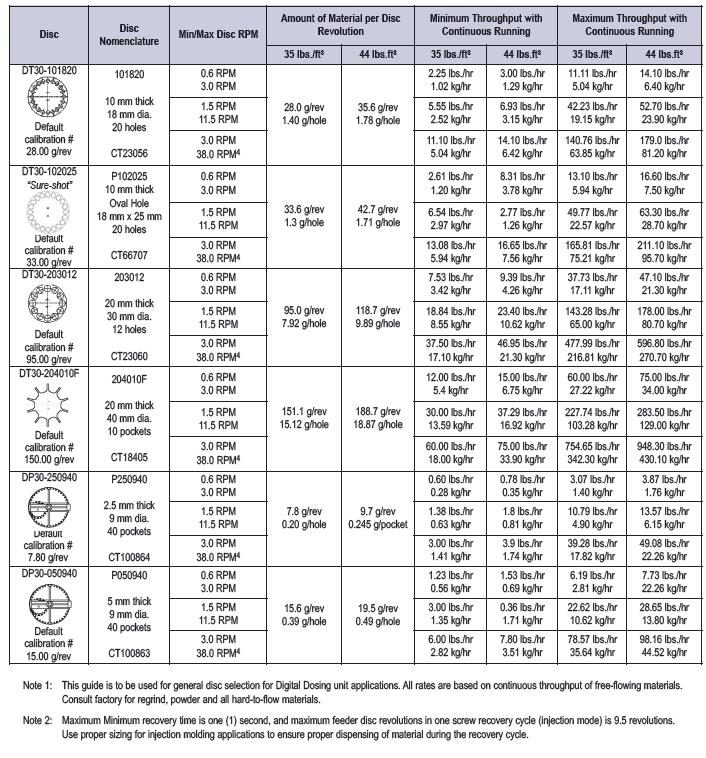
19 Screw Recovery Time. The screw recovery time is the estimated screw recovery time, and is used as the initial value for validating the recipe. Actual screw recovery times as measured by the presence of the screw recovery signal, are used to fine-tune the feed rate during operation. The estimated time must be at least ½ of the actual recovery time. If less than ½, the feeder will interpret the recovery signal as a purge cycle. Calibration weight. Calibration weight is determined from the following tables, and is dependant on the disc installed in the feeder. This weight is the amount of standard density material dispensed by the feeder during one revolution of the disc. This weight is used as the initial value for recipe validation and feed rate calculation. If samples are not weighed as described in the next section, this value is used during operation. The weight can be entered in ounces or grams. The unit of measure is changed by pressing the units button at the middle right of the screen. Changing the unit of measure will NOT change the value displayed on the screen. The value initially displayed is the weight which would result in a motor speed of 25%. The valid range of values would then be ¼ to 5 times this initial value. DD Pellet Discs Disc Calibration Number No. of Pockets Disc Thickness DD mm DD DD DD mm 19 of 96
20 DT Pellet & Regrind Discs Disc Thickness Disc Calibration Number No. of Pockets DP Powder Discs 10 mm DT DT ( Sure-shot - 20 oval holes) Oval Calibration Disc Number DP Disc Thickness 5mm 20mm DT DT DP mm Additive Sample weighing. Weighing samples of additive provides for more precise control of feed rate. Up to 5 samples can be weighed. All weights entered are averaged to arrive at a value to be used during operation. The weighing process may be skipped altogether, in which case the calibration weight is used for calculations of feed rate. See the section Weight Calibration at the end of this section. Feeder Configuration Simple extrusion: Touch the ACS logo on the main menu screen to access the configuration menu. See section # for details. Feeder Type Selection. Select simple extrusion. 20 of 96
21 Maximum Motor speed. Enter motor RPM. Encoder pulses per disk revolution. See table. Manufacturer Motor Color RPM Encoder Pulses Bodine Black & silver Bodine Black & silver Bodine Black & silver Bodine Black & silver Motor and alarm utilty selection 21 of 96
22 Drive tuning. Perform drive tuning. See section # for details. Speed Alarm setup. Select alarm option Alarm & stop, alarm only, or no alarm. GR or OZ Select the measure commonly used at your facility. Extrusion Press (GR/KG/OZ/LB) Select the measure commonly used at your facility. Additive sensor. Select the no sensor, alarm only, or alarm & stop. 22 of 96
23 Virgin material sensor. Select the no sensor, alarm only, or alarm & stop. Recipe Setup for Simple Extrusion: 1. Turn power switch to ON position. In order to calculate the correct motor speed required to feed the desired amount of additive, the following data must be entered: Additive % 1) Additive % 2) Throughput 3) Calibration weight. In addition, for the greatest accuracy, samples of the additive should be weighed and entered. The % additive specifies the proportion of additive to virgin material as a percentage of throughput. For example, if the throughput is 200 grams per minute and 8.5 grams of additive are required, the additive percentage would be After the additive value has been entered, press the Next button to navigate to the Throughput screen. 23 of 96
24 Throughput. Press throughput specifies the total weight of material through the extruder per minute. The value can be entered in grams, kilograms, ounces, or pounds per minute. The unit of measure is changed by pressing the units button at the middle right of the screen. Changing the unit of measure will NOT change the value displayed on the screen. It is important that this value be adjusted whenever the extruder speed changes. Calibration weight. Calibration weight is determined from the following tables, and is dependant on the disc installed in the feeder. This weight is the amount of standard density material dispensed by the feeder during one revolution of the disc. This weight is used as the initial value for recipe validation and feed rate calculation. If samples are not weighed as described in the next section, this value is used during operation. The weight can be entered in ounces or grams. The unit of measure is changed by pressing the units button at the middle right of the screen. Changing the unit of measure will NOT change the value displayed on the screen. The value initially displayed is the weight which would result in a motor speed of 25%. The valid range of values would then be ¼ to 2.5 times this initial value. DD Pellet Discs Disc Calibration Number No. of Pockets Disc Thickness DD mm DD DD mm DD of 96
25 DT Pellet & Regrind Discs Disc Thickness 10 mm 20mm Disc Calibration No. of Number Pockets DT DT ( Sure-shot Oval oval holes) DT DT DP Powder Discs Disc Calibration Disc Number Thickness DP mm DP mm Feeder Configuration Extrusion follower: Touch the ACS logo on the main menu screen to access the configuration menu. See section # for details. Feeder Type Selection. Select extrusion follower. Select press signal type, 0-10V, 0-20mA, or 4-20mA. 25 of 96
26 Enter/Read Minimum press signal. See section # for details. Enter/Read Maximum press signal. See section # for details. Maximum Motor speed Enter motor speed. Encoder pulses per disk revolution. See table. Manufacturer Motor Color RPM Encoder Pulses Bodine Black & silver Bodine Black & silver Bodine Black & silver Bodine Black & silver of 96
27 Motor and alarm utilty selection Drive tuning Perform drive tuning. See section # for details. Speed Alarm setup. Select alarm option Alarm & stop, alarm only, or no alarm. GR or OZ Select the measure commonly used at your facility. Extrusion Press (GR/KG/OZ/LB) Select the measure commonly used at your facility. 27 of 96
28 Additive sensor. Select the no sensor, alarm only, or alarm & stop. Virgin material sensor. Select the no sensor, alarm only, or alarm & stop. Recipe Setup for Simple Extrusion: In order to calculate the correct motor speed required to feed the desired amount of additive, the following data must be entered: Additive % 1) Additive % 2) Throughput 3) Throughput RPM 4) Calibration weight. In addition, for the greatest accuracy, samples of the additive should be weighed and entered. The % additive specifies the proportion of additive to virgin material as a percentage of throughput. For example, if the throughput is 200 grams per minute and 8.5 grams of additive are required, the additive percentage would be After the additive value has been entered, press the Next button to navigate to the Throughput screen. 28 of 96
29 Throughput. Press throughput specifies the total weight of material through the extruder per minute. The value can be entered in grams, kilograms, ounces, or pounds per minute. The unit of measure is changed by pressing the units button at the middle right of the screen. Changing the unit of measure will NOT change the value displayed on the screen. This value is the throughput corresponding to a specific extruder RPM, which will be entered on the following screen. Given these reference values, the correct feed rate can be determined for any extruder speed. Note that the minimum and maximum press speeds and signal levels must be entered correctly in Setup. Throughput Speed. The press speed corresponding to the throughput value entered on the previous screen. Given these reference values, the correct feed rate can be determined for any extruder speed. Note that the minimum and maximum press speeds and signal levels must be entered correctly in Setup. Calibration weight. Calibration weight is determined from the following tables, and is dependant on the disc installed in the feeder. This weight is the amount of standard density material dispensed by the feeder during one revolution of the disc. This weight is used as the initial value for recipe validation and feed rate calculation. If samples are not weighed as described in the next section, this value is used during operation. The weight can be entered in ounces or grams. The unit of measure is changed by pressing the units button at the middle right of the screen. Changing the unit of measure will NOT change the value displayed on the screen. The value 29 of 96
30 initially displayed is the weight which would result in a motor speed of 25%. The valid range of values would then be ¼ to 2.5 times this initial value. DD Pellet Discs Disc Calibration Number No. of Pockets Disc Thickness DD mm DD DD mm DD DT Pellet & Regrind Discs Disc Thickness 10 mm 20mm Disc Calibration No. of Number Pockets DT DT ( Sure-shot Oval oval holes) DT DT DP Powder Discs Disc Calibration Disc Number Thickness DP mm DP mm Additive Sample weighing. Weighing samples of additive provides for more precise control of feed rate. Up to 5 samples can be weighed. All weights entered are averaged to arrive at a value to be used during operation. The weighing process may be skipped altogether, in which case the calibration weight is used for calculations of feed rate. Weight Calibration. The final step of recipe setup is weight calibration. This procedure is common to all types of presses supported. After entering the calibration weight, pressing the Next button displays the following screen: 30 of 96
31 Press the Menu button to skip the weighing procedure and use the calibration weight for feed rate calculations. Note that using the calibration weight is not as accurate as weighing samples. Pressing the Next button displays screen #1. Screen 1. Initial preparation for weighing samples. The access cover to the calibration chamber should be removed / opened. The container used to catch and hold the samples should be tared (place the container on the scale and zero the scale). The container should then be placed in the calibration chamber. Press Next when these steps have been completed. The motor will begin to run as Screen 2 will be displayed. Screen 2. The disc will make one complete revolution, insuring all pockets are filled with additive material prior to actual weighing. Motor speed is 25%. Screen 3. When the motor stops, screen 3 is displayed. Discard sample and replace container in calibration box. Press Next starts the motor and displays Screen of 96
32 Screen 4. The disc will make one complete revolution, dispensing additive into the tray. Motor speed is 25%. When the motor stops, Screen 5 is displayed. Screen 5. Weigh the sample, making note of the weight for entry on the next screen. Discard sample & replace tray in calibration box. Press Next to display Screen 6. Screen 6. Enter the sample weight obtained from the previous cycle of the feeder. The unit of measure will be the same as used for the calibration weight. Pressing the Enter symbol on the screen keypad displays Screen of 96
33 Screen 7. The screen displays the running average of sample weights, as well as the number of samples taken. Pressing Next will repeat the process at Screen 4 if less than 5 samples have been taken, otherwise Screen 8 will be displayed. Screen 8. The tray should be removed from the calibration chamber. The access cover should be replaced / closed. Weight Calibration is complete. Note that at any time in the process, the Menu button may be pressed to abort the weight calibration process. Any sample weights, if any, are used to calculate the average weight. If no sample weights are entered, the calibration weight is used for calculations. Using less than 5 samples may affect feeder accuracy. 33 of 96
34 Chapter 3: Installation and Operation 3-1 Installation Hopper Piece Processing Machine Direction of Material Flow Figure 4. Digital Dosing Feeder Assembly 1. The Digital Dosing additive feeder is not affected by machine vibration, so the best performance is achieved by mounting the feeder directly on the feed throat of the molding machine or extruder (see Figure 4). The inlet into the process machine must be greater than 2 diameter, or an adapter may be necessary. If an adapter is required, it must be designed so that there are no edges where material can hang up - it must be smooth to promote consistent material flow. 34 of 96
35 2. The following applications require a larger feed stand (optional 3 or 4 ) to prevent material bridging: o Machines with a total throughput over 200 lbs./hr. o Machines running regrind larger than 5/16 screen size o Processes with a high percentage of regrind (>30%) o Non-free flowing virgin material, i.e. powder o Consult factory for any special requirements. 3. Optimum mounting of the Digital Dosing feeder is shown in Figure 4, with the additive being dosed in the first few flights of the feed screw. 4. The controller should be remote mounted for operator convenience. The control unit must not be exposed to temperatures above 45 C (115 F), or excessive moisture. 5. Electrical connection to process machine: Injection Molding: Connect the cycle/run cable (thin, gray two-conductor cable) to a set of dry (NO VOLTAGE) contacts that CLOSE for the duration of the screw recovery. (See Figure 5.) TB #10 X5 Relay contact Injection molding Digital Dosing controller Figure 5. Electrical Interface Connection Diagram Injection Molding or Extrusion - Constant 35 of 96
36 Extrusion - Constant: Wire the cycle/run cable (two- conductor gray cable) to a set of dry (NO VOLTAGE) contacts that CLOSE when the screw rotates. (See Figure 5.) The connection inside the controller should be on terminal block #10 and PLC input X5. Extrusion - Proportional: Wire the cycle/run cable to the extruder signal output that is proportional to the extruder speed. The signal can be 0-10 VDC or 0-20 ma or 4-20 ma. Jumpers J1 and J2 should be installed for 0-20mA or 4-20mA, and removed for 0-10VDC. NOTES: 1. Signal voltage from the extruder must to be isolated. Consult factory for other signal requirements. External signal converter may be required. 2. Zero input corresponds to zero screw speed and no additive dosing. Maximum input corresponds to maximum screw speed. TB #51 _ TB # VDC or 0/4-20 ma Extruder output Digital Dosing controller Figure 6. Analog Extruder Input Connection Diagram Extrusion - Proportional 36 of 96
37 3-2 Initial Operation The control system is factory-programmed. However, specific values need to be verified prior to operation (basic parameter settings). The input values will be saved and still be available if the feeder is switched off, or a power failure occurs. Please refer to Appendix B for these values. Extrusion operations require a span factor to be entered into the basic settings. These are also explained in Appendix B. Prior to putting your new Digital Dosing feeder on-line: Configure the feeder control for motor speed, encoder pulses, sensors, and alarm options. o Tune the drive. o Enter a recipe. o Calibrate the additive weight for best accuracy. NOTE: Recipe parameters are different for Injection Molding, Extrusion Constant, and Extrusion - Proportional operation. See each individual section for details Once the feeder is on-line, recipes can be saved for later recall (up to 50 standard). 37 of 96


38 3-3 Recipes Recipe Menu The Recipe menu allows selection, editing, and deletion of recipes. The current recipe is displayed in the upper left corner. A different recipe can be selected by pressing the recipe value. Selecting a new recipe will automatically change the screen to the 1 st recipe entry/editing screen. Pressing the Edit Recipe button will display the 1 st recipe entry/edit screen. See following section. Pressing the New Recipe button will display the New Recipe menu. Pressing the Edit Recipe button will display the 1 st recipe entry/edit screen. See following section. Select a new recipe by pressing the recipe # value. Press the Next Avail button to use the next available empty / unused recipe number. Pressing the Delete Recipe button will display a confirmation screen as follows: Press the Delete Recipe button to clear all values from the current recipe. Pressing the Keep Recipe button will retain the values and return to the Recipe Menu screen. 38 of 96
 Additive % 6) Shot Size 7) Screw Recovery Time.")
39 Enter / Edit Recipes. Injection molding. In order to calculate the correct motor speed required to feed the desired amount of additive, the following data must be entered: Additive % 5) Additive % 6) Shot Size 7) Screw Recovery Time. 8) Calibration weight. In addition, for the greatest accuracy, samples of the additive should be weighed and entered. The % additive specifies the proportion of additive to virgin material as a percentage of throughput. For example, if the shot size is 200 grams and 8.5 grams of additive are required, the additive percentage would be After the additive value has been entered, press the Next button to navigate to the Shot Size screen. Shot Size The shot size specifies the total capacity of the mold in use on the press. The value can be entered in grams, kilograms, ounces, or pounds. The unit of measure is changed by pressing the units button at the middle right of the screen. Changing the unit of measure will NOT change the value displayed on the screen. 39 of 96

40 Screw Recovery Time. The screw recovery time is the estimated screw recovery time, and is used as the initial value for validating the recipe. Actual screw recovery times as measured by the presence of the screw recovery signal, are used to fine-tune the feed rate during operation. The estimated time must be at least ½ of the actual recovery time. If less than ½, the feeder will interpret the recovery signal as a purge cycle. Calibration weight. Calibration weight is determined from chart 5.1, and is dependant on the disc installed in the feeder. This weight is the amount of standard density material dispensed by the feeder during one revolution of the disc. This weight is used as the initial value for recipe validation and feed rate calculation. If samples are not weighed as described in the next section, this value is used during operation. The weight can be entered in ounces or grams. The unit of measure is changed by pressing the units button at the middle right of the screen. Changing the unit of measure will NOT change the value displayed on the screen. The value initially displayed is the weight which would result in a motor speed of 25%. The valid range of values would then be ¼ to 5 times this initial value. Additive Sample weighing. Weighing samples of additive provides for more precise control of feed rate. Up to 5 samples can be weighed. All weights entered are averaged to arrive at a value to be used during operation. The weighing process may be skipped altogether, in which case the calibration weight is used for calculations of feed rate. See the section Weight Calibration at the end of this section. 40 of 96
41 Simple Extrusion Recipe. In order to calculate the correct motor speed required to feed the desired amount of additive, the following data must be entered: Additive % 4) Additive % 5) Throughput 6) Calibration weight. In addition, for the greatest accuracy, samples of the additive should be weighed and entered. The % additive specifies the proportion of additive to virgin material as a percentage of throughput. For example, if the throughput is 200 grams per minute and 8.5 grams of additive are required, the additive percentage would be After the additive value has been entered, press the Next button to navigate to the Throughput screen. Throughput. Press throughput specifies the total weight of material through the extruder per minute. The value can be entered in grams, kilograms, ounces, or pounds per minute. The unit of measure is changed by pressing the units button at the middle right of the screen. Changing the unit of measure will NOT change the value displayed on the screen. It is important that this value be adjusted whenever the extruder speed changes. 41 of 96
42 Calibration weight. Calibration weight is determined from chart 5.1, and is dependent on the disc installed in the feeder. This weight is the amount of standard density material dispensed by the feeder during one revolution of the disc. This weight is used as the initial value for recipe validation and feed rate calculation. If samples are not weighed as described in the next section, this value is used during operation. The weight can be entered in ounces or grams. The unit of measure is changed by pressing the units button at the middle right of the screen. Changing the unit of measure will NOT change the value displayed on the screen. The value initially displayed is the weight which would result in a motor speed of 25%. The valid range of values would then be ¼ to 2.5 times this initial value. Additive Sample weighing. Weighing samples of additive provides for more precise control of feed rate. Up to 5 samples can be weighed. All weights entered are averaged to arrive at a value to be used during operation. The weighing process may be skipped altogether, in which case the calibration weight is used for calculations of feed rate. See the section Weight Calibration at the end of this section. Extrusion Follower Recipe. In order to calculate the correct motor speed required to feed the desired amount of additive, the following data must be entered: Additive % 1) Additive % 5) Throughput 6) Throughput RPM 7) Calibration weight. In addition, for the greatest accuracy, samples of the additive should be weighed and entered. 42 of 96


43 The % additive specifies the proportion of additive to virgin material as a percentage of throughput. For example, if the throughput is 200 grams per minute and 8.5 grams of additive are required, the additive percentage would be After the additive value has been entered, press the Next button to navigate to the Throughput screen. Throughput. Press throughput specifies the total weight of material through the extruder per minute. The value can be entered in grams, kilograms, ounces, or pounds per minute. The unit of measure is changed by pressing the units button at the middle right of the screen. Changing the unit of measure will NOT change the value displayed on the screen. This value is the throughput corresponding to a specific extruder RPM, which will be entered on the following screen. Given these reference values, the correct feed rate can be determined for any extruder speed. Note that the minimum and maximum press speeds and signal levels must be entered correctly in Setup. Throughput Speed. The press speed corresponding to the throughput value entered on the previous screen. Given these reference values, the correct feed rate can be determined for any extruder speed. Note that the minimum and maximum press speeds and signal levels must be entered correctly in Setup. Calibration weight. 43 of 96


44 Calibration weight is determined from chart 5.1, and is dependent on the disc installed in the feeder. This weight is the amount of standard density material dispensed by the feeder during one revolution of the disc. This weight is used as the initial value for recipe validation and feed rate calculation. If samples are not weighed as described in the next section, this value is used during operation. The weight can be entered in ounces or grams. The unit of measure is changed by pressing the units button at the middle right of the screen. Changing the unit of measure will NOT change the value displayed on the screen. The value initially displayed is the weight which would result in a motor speed of 25%. The valid range of values would then be ¼ to 2.5 times this initial value. Additive Sample weighing. Weighing samples of additive provides for more precise control of feed rate. Up to 5 samples can be weighed. All weights entered are averaged to arrive at a value to be used during operation. The weighing process may be skipped altogether, in which case the calibration weight is used for calculations of feed rate. 3-4 Calibration The final step of recipe setup is weight calibration. This procedure is common to all types of presses supported. After entering the calibration weight, pressing the Next button displays the following screen: Press the Menu button to skip the weighing procedure and use the calibration weight for feed rate calculations. Note that using the calibration weight is not as accurate as weighing samples. Pressing the Next button displays screen #1. Screen 1. Initial preparation for weighing samples. The access cover to the calibration chamber should be removed / opened. The container used to catch and hold the samples should be tared (place the container on the scale and zero the scale). The container should then be placed in the calibration chamber. Press Next when these steps have been completed. The motor will begin to run as Screen 2 will be displayed. 44 of 96


45 Screen 2. The disc will make one complete revolution, insuring all pockets are filled with additive material prior to actual weighing. Motor speed is 25%. Screen 3. When the motor stops, screen 3 is displayed. Discard sample and replace container in calibration box. Press Next starts the motor and displays Screen 4. Screen 4. The disc will make one complete revolution, dispensing additive into the tray. Motor speed is 25%. When the motor stops, Screen 5 is displayed. 45 of 96


46 Screen 5. Weigh the sample, making note of the weight for entry on the next screen. Discard sample & replace tray in calibration box. Press Next to display Screen 6. Screen 6. Enter the sample weight obtained from the previous cycle of the feeder. The unit of measure will be the same as used for the calibration weight. Pressing the Enter symbol on the screen keypad displays Screen 7. Screen 7. The screen displays the running average of sample weights, as well as the number of samples taken. Pressing Next will repeat the process at Screen 4 if less than 5 samples have been taken, otherwise Screen 8 will be displayed. 46 of 96


47 Screen 8. The tray should be removed from the calibration chamber. The access cover should be replaced / closed. Weight Calibration is complete. Note that at any time in the process, the Menu button may be pressed to abort the weight calibration process. Any sample weights, if any, are used to calculate the average weight. If no sample weights are entered, the calibration weight is used for calculations. Using less than 5 samples may affect feeder accuracy. 3-5 Status screens Status Screens The status screens reflect the state of the feeder during operation. The status screens are accessed by pressing the Status button on the main menu. Prerequisites. Before the status screens can be displayed, the current recipe must be valid & complete.if the current recipe is not valid, an advisory screen is displayed : Invalid Recipe: 47 of 96
48 Common Elements Buttons Press the Start button to begin feeding operation using the current recipe. Press the Stop button to end feeding operation. Press the Next button to display the next Status screen. There are 3 status screens available while the A250 is running: Totalizer screen Throughput screen Motor Speed screen When the A250 is stopped, a 4 th screen is available The Manual Run / Jog screen. Press the Menu button to display the Main Menu screen. 48 of 96
49 Speed Status Indicator If the speed alarm only option is selected in the configuration section, the following indicators are enabled. Displays when the feeder speed exceeds the calculated speed by greater than that specified on the speed alarm setup screen. The screen will change to a steady orange color. Displayed when the feeder speed is less than that specified on the speed alarm setup screen. The screen will change to a steady orange color. Displayed when no encoder pulses are detected from the drive motor. The screen will change to a steady orange color. Displayed when the calculated motor speed is greater than the rated motor speed. The screen will change to orange and flash in this condition. Displayed when the calculated motor speed is less than 5% of the rated motor speed. The screen will change to orange and flash in this condition. Disc Motor Indicator Press Signal Indicator Displayed when the drive motor is running. Displayed when press signal is detected: Injection Screw recovery signal. Simple Extrusion Press Run signal. Extrusion Follower Analog speed signal. 49 of 96


50 Totalizer Screen Displays total additive dosed since: A. Recipe change. Modifying the current recipe will not reset the total. Or B. Totalizer reset. The total is displayed in KG if recipe additive is measured in grams or kilograms. The total is displayed in LB if the recipe additive is measured in ounces or pounds. Pressing the reset button resets the total display to zero. Throughput Screen Displays the calculated throughput. Injection Press. Throughput is based on recipe data and measured average screw recovery time. A running average of the 5 most recent screw recovery times is used. Simple extrusion. Throughput is based on recipe data. Extrusion Follower. Throughput is based on recipe data and the current press speed signal. Motor Speed Screen 50 of 96
 Displays the 5 most recent screw recovery times (latest on top), as well as")


51 Displays the current motor speed when running, and the calculated speed when stopped. Screw Recovery Times Screen (Injection only) Displays the 5 most recent screw recovery times (latest on top), as well as the simple average and weighted average. Manual Run / Jog Screen This screen is only available when the A250 control is stopped. This screen provides the means to purge / clear additive, prime additive, etc.. Decel buttons. The speed at which the motor will run, jog, or purge. Adjust using the Accel and Pressing and holding either of these buttons will adjust the motor run speed by approximately 1% of max speed every ½ second. The minimum speed is 5%, while the maximum speed is 100%. The default speed is 50%. 51 of 96

52 button is held. Pressing and holding the Jog button will run the motor at the indicated speed for as long as the The length of time the motor will run when the Run Motor button is pressed. Adjustable from 0 to 999 seconds. The default is 0 seconds. Pressing the Run Motor button causes the motor to run for the indicated time. While the motor is running, it can be stopped by pressing the Stop Motor button. Pressing the Purge button will cause the feeder to run at the indicated rate for the duration of the next screw recovery signal. The purge mode will be cancelled at the end of the screw recovery signal or as noted below. Pressing the Purge button when purge mode is active will cancel purge mode. Configuration. Navigation. The top level of System setup navigation is the System Setup Menu: System Setup Menu The configuration screens are grouped by similar function. Each of the buttons on the System Setup Menu screen will navigate to the 1 st screen of each group. From each configuration screen, any of the following screens can be reached: 52 of 96
53 A) The Main Menu, using the Menu button. B) The System Setup Menu, using the Done button. C) The next Configuration screen, using the Next button. D) The previous Configuration screen, using the Prev button. System Setup Navigation Buttons. Navigates to the previous screen in the setup chain. See Table 4.1. Navigates to the next screen in the setup chain. See Table 4.1. Navigates to the Setup Menu screen. Navigates to the Main Menu screen. From the Drive Tuning screen, returns to the Max RPM screen. From the Speed Alarm screen, returns to the Encoder Pulses screen. 53 of 96
54 Table 4.1 Injection Press Screen # Title/Function Prev Screen Next Screen 60 Press Type N/A Max Motor Speed 61 Max Motor Speed Press Type Encoder Pulses 62 Encoder Pulses Max Motor Speed Tune & Speed alarm 76 Tune & Speed alarm Encoder Pulses Default Add. Measure 63 Default Add. Measure Tune & Speed alarm Default Shot Measure 64 Default Shot Measure Default Add. Measure Additive Sensor 6A Additive Sensor Default Shot Measure Virgin Sensor 6B Virgin Sensor Additive Sensor Passwords 6C Passwords Virgin Sensor Digital I/O Monitor 6D Digital I/O Monitor Passwords Analog I/O Monitor 6E Analog I/O Monitor Digital I/O Monitor Setup Menu Simple Extrusion Press Screen # Title/Function Prev Screen Next Screen 60 Press Type N/A Max Motor Speed 61 Max Motor Speed Press Type Encoder Pulses 62 Encoder Pulses Max Motor Speed Tune & Speed alarm 76 Tune & Speed alarm Encoder Pulses Default Add. Measure 63 Default Add. Measure Tune & Speed alarm Default Shot Measure 65 Default Thruput Meas. Default Add. Measure Additive Sensor 6A Additive Sensor Default Thruput Meas. Virgin Sensor 6B Virgin Sensor Additive Sensor Passwords 6C Passwords Virgin Sensor Digital I/O Monitor 6D Digital I/O Monitor Passwords Analog I/O Monitor 6E Analog I/O Monitor Digital I/O Monitor Setup Menu Extrusion Follower Press Screen # Title/Function Prev Screen Next Screen 60 Press Type N/A Max Motor Speed 54 of 96
55 61 Max Motor Speed Press Type Encoder Pulses 62 Encoder Pulses Max Motor Speed Tune & Speed alarm 76 Tune & Speed alarm Encoder Pulses Default Add. Measure 63 Default Add. Measure Tune & Speed alarm Default Shot Measure 65 Default Thruput Meas. Default Add. Measure Additive Sensor 6A Additive Sensor Default Thruput Meas. Virgin Sensor 6B Virgin Sensor Additive Sensor Press Signal Type 66 Press Signal Type Virgin Sensor Min Signal set 67 Min Signal set Press Signal Type Max Signal set 68 Max Signal set Min Signal set Passwords 6C Passwords Max Signal set Digital I/O Monitor 6D Digital I/O Monitor Passwords Analog I/O Monitor 6E Analog I/O Monitor Digital I/O Monitor Setup Menu 55 of 96
 An injection molding press provides a contact closure during the Screw Recovery Cycle, or that period when")
56 Feeder Type. Feeder type is selected by pressing the button in the upper-right corner. The button text changes with each press of the button in the following order: (Default Mode) An injection molding press provides a contact closure during the Screw Recovery Cycle, or that period when the press is loading material prior to injection into the mold cavity. The 2 types of extrusion presses are dependant on the input signal provided to the A250 additive feeder. Simple extrusion provides a contact closure to input 5 of the PLC, and it is assumed that the press is always run at the speed entered for the active recipe. Extrusion follower provides an analog signal to channel 0 of the analog module which changes in relation to the speed (throughput) of the press. 56 of 96
.")
 Press the Min button. 3) Check rotation direction. Disk should turn (counterclockwise). 4) Swap A+ & A- leads With Power Off to change rotation direction. 5) Press Max button.")
57 Maximum Motor Speed. The maximum motor RPM is the maximum rated speed for the motor being used with the A250 control. The default nominal value is 11.5 RPM. This value should be changed to reflect the actual motor RPM based on motor type and tuning results (See Drive Tuning following this section). Initially, this value should be set to the nameplate RPM for the motor/gearbox being used, before proceeding to Drive Tuning. 1) Turn the Accel & Decel pots fully counter-clockwise. 2) Press the Min button. 3) Check rotation direction. Disk should turn (counterclockwise). 4) Swap A+ & A- leads With Power Off to change rotation direction. 5) Press Max button. 6) Adjust max pot to adjust max speed to match target value. 7) Press Min button. 8) Adjust min pot to adjust min speed to match target value. 9) Repeat steps 5-8 until readings stabilize. 10) If maximum speed value cannot be obtained, change max RPM on the Maximum Motor Speed screen to match the closest value obtained on this screen. Encoder Pulses. The encoder pulses are determined by the number of encoder steps per motor revolution (usually 30) multiplied by the gearbox ratio. In the case of the standard motor, the ratio is 190:1, so 30 X 190 = To change the value, press the value on the screen to activate the keyboard. Key in the correct value and press the key. Manufacturer Motor Color RPM Encoder Pulses 57 of 96

58 Bodine Black & silver Bodine Black & silver Bodine Black & silver Bodine Black & silver Motor and alarm utilty selection The Speed Alarm settings screen can be activated by pressing the Speed Alarm button. The Drive Tuning screen can be activated by pressing the Tune Drive button. See the following sections for these screens. 58 of 96


59 Drive Tuning. The drive tuning screen is provided as an aid to tuning the drive to match the motor and load of the A250 feeder. Pressing the Min button will send the minimum drive signal to the controller. Pressing the Max button will send the maximum drive signal to the controller. Pressing the Stop button (or leaving this screen) will terminate any signal sent to the controller. The numbers on the left are the target min/max values. The numbers on the right are the actual speed values. A small screwdriver, preferably non-metallic, is needed to tune the drive. Tune the drive as follows: Speed Alarm The reaction to deviations from the commanded speed are controlled via this screen. Speed deviation specifies the window within which the motor speed must be for normal operation. The Alarm Delay specifies the minimum time the speed must be outside this window before generating an alarm. For example, if the default values are used and the commanded speed is 5 RPM, the controller will alarm if the speed is less than 4.75 RPM or more than 5.25 RPM for at least 2 seconds. The specific response to the alarm condition can be selected by pressing the button in the lower left corner as follows: Take no action. See Status screens for indicator. Activate alarm screen & alarm output on PLC. 59 of 96

60 Activate alarm screen & alarm outputs, and stop the feeder. See Status Screens section for speed alarm screen details. Default Additive Measure. This screen sets the default measure for additive weight in recipes. While the measure can be changed in any recipe, this screen allows selection of the most commonly used unit of measure. Press the upper right corner to select: Or Grams Ounces 60 of 96


61 Default Shot Size / Throughput Measure. Injection Press. Extrusion Press This screen sets the default measure for overall weight in recipes. While the measure can be changed in any recipe, this screen allows selection of the most commonly used unit of measure. Press the upper right corner to select: Grams Kilograms Ounces Pounds 61 of 96
 running. Sensor is present.")
62 Additive / Virgin Material Sensor. These screens select whether an additive (or virgin) material sensor is present and if so, what action to take when the sensor detects no material. Press the button in the upper right corner to sequence through the following options: No sensor is present. (Default) running. Sensor is present. Display alarm screen & activate alarm output, but keep feeder operation. Sensor is present. Display alarm screen & activate alarm output, and stop feeder 62 of 96
 0 to 20 ma (milliamps) DC. 0 to 20 ma (milliamps) DC. Minimum Press Signal.")
63 Press Signal Type. (Extrusion Follower only) This screen selects the type of analog signal provided by the press to communicate the press speed. Press the button in the upper right corner to select from the following: 0 to 10 volts DC. (Default) 0 to 20 ma (milliamps) DC. 0 to 20 ma (milliamps) DC. Minimum Press Signal. (Extrusion Follower only) This screen configures the minimum speed of the press and the analog signal associated with that speed. Press the top number to enter the minimum speed, using the screen keyboard, in RPM for the press. The voltage associated with that speed can either be entered manually by pressing the value and entering the value on the keyboard, or by pressing the number at the lower left to read the voltage level currently being sent by the press. The unit of measure, A or V, is determined by the selection made on the Press Signal Type screen. 63 of 96


64 Maximum Press Signal. (Extrusion Follower only) This screen configures the maximum speed of the press and the analog signal associated with that speed. Press the top number to enter the maximum speed, using the screen keyboard, in RPM for the press. The voltage associated with that speed can either be entered manually by pressing the value and entering the value on the keyboard, or by pressing the number at the lower left to read the voltage level currently being sent by the press. The unit of measure, A or V, is determined by the selection made on the Press Signal Type screen. Note: The Minimum & maximum press signal values are used to calculate the relationship between input signal and extruder speed. Operation at speeds below the minimum and above the maximum are possible, subject to input signal limits. See appendix # for examples. Passwords Screen. The passwords screen allow the entry of Operator & Setup passwords. By default, these are set to 0, which disables the password requirement. Setting the password to a non-zero value activates password protection. To set / change the Operator password, press the value next to Operator and enter the new password using the screen keyboard. To change the password duration, press the duration value & enter the new duration using the screen keyboard. The Setup password and duration are entered in the same way. Refer to Table 4.2 for password requirements based on which passwords are enabled. 64 of 96

65 Table 4.2 Password requirements. No Passwords Operator Only Setup Only Operator and. Set Active Active Setup Active Recipe Functions X O X O System Start/Stop X O X O Manual Jog/Run X O X O System Setup X O S S X - None O - Operator S - Setup Digital I/O Monitor. This screen monitors the PLC inputs and outputs. When an input or output is on, the indicator is displayed white on black -. When an input or output is off, the indicator is displayed as black on white -.. If using the Modbus communications option, the node (station) number is set here. Valid node numbers are of 96

66 Analog / Encoder Monitor. This screen monitors the analog input & output, as well as the raw encoder value input. Additionally, the encoder can be connected to an alternate PLC input to help troubleshoot encoder problems. To change the encoder input, disconnect power & move the encoder signal wire from input 0 to any of inputs 1, 2, or 3. Restore power, navigate back to this screen, and change the ENC CH # to match the PLC input chosen. When the Jog Mtr button is pressed, the motor will run at 25% speed for as long as the button is pressed. The top line will display the raw encoder value. The MTR OUT value will be 500 for KB or Bodine drives, or 1000 for Dart drives. The PRESS value will be , depending on the press signal, if no press signal is connected, the value will be at or near zero. 3-6 Optional Features Optional equipment for the Digital Dosing Additive Feeder includes: Loaders Several versions of automatic loaders are available to keep the additive (or virgin material) supply hoppers full consult with your sales contact for the unit that best fits your needs. Hoppers Several versions of hoppers are available and can be used in different applications - consult with your sales contact for the unit that best fits your needs. Alarms Several alarm options are available for the Digital Dosing feeder. Options include both audible horns and flashing lights. An optional no voltage alarm relay can be connected to the user s central alarm system. Level switches (probes) To adjust the level switches: 1. Turn the controller ON. 2. Fill the dosing station until the level sensor is one-third covered. 3. Remove the plastic screw (M3) on the back of the level sensor (see Figure 7) 66 of 96
67 LED Yellow (Station) on: Station Filled off: Station Emptied LED Green (Level Probe) on: Power Supply Available off: Power Supply Not Available npn: Normally Closed pnp: Normally Open 1 0 npn: Normally Open pnp: Normally Closed Trim-pot with Plastic Screw M3 Cable Blind Lid Protective Screw Figure 7. Level Sensor Adjustment Screw Level Probe 4. Turn the trim-pot until the yellow control lamp just switches off. NOTE: Turning the trim-pot to the left decreases the switching sensitivity, and turning it to the right increases the sensitivity. 5. Fill the dosing station until the level probe is two-thirds covered. The yellow control lamp should now switch on again. If not, repeat Step Reinstall the plastic screw (M3). NOTE: The sliding switch under the cover must be set on 0. Communication Protocol Interfaces The Digital Dosing feeder can be controlled remotely through ODBUS RTU protocol. Contact the Sales Department at for more information. OPTIONAL Additive Hoppers Various styles of additive hoppers and options are also available for the Digital Dosing feeder. Contact the Sales Department at for more information. 67 of 96
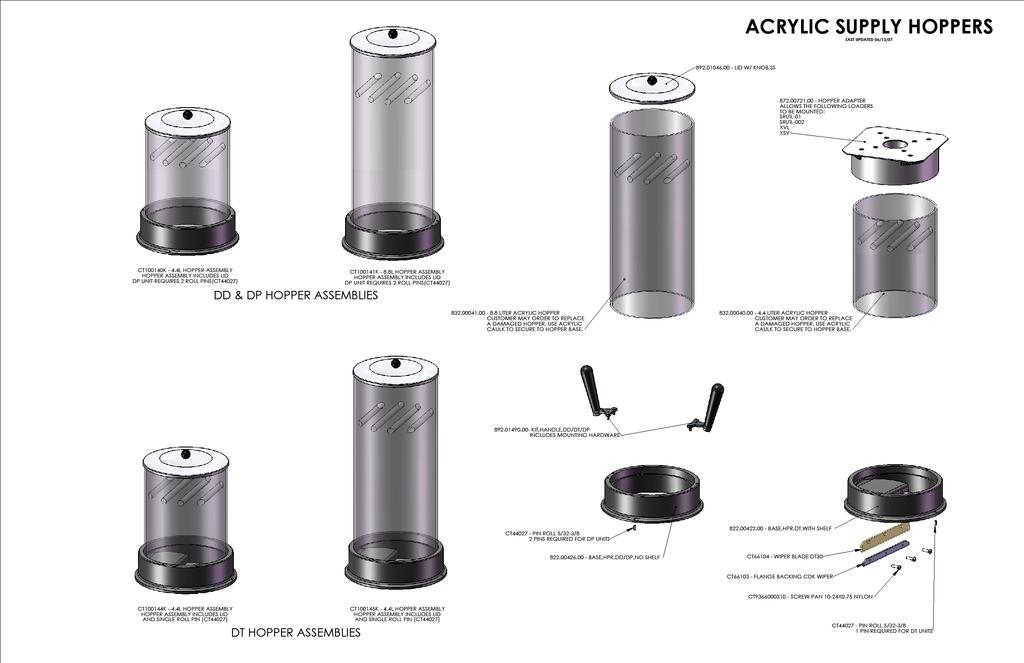
68 68 of 96
69 69 of 96

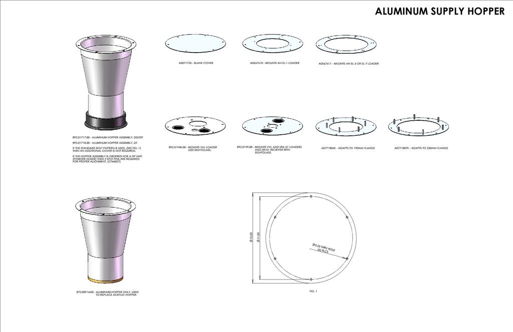
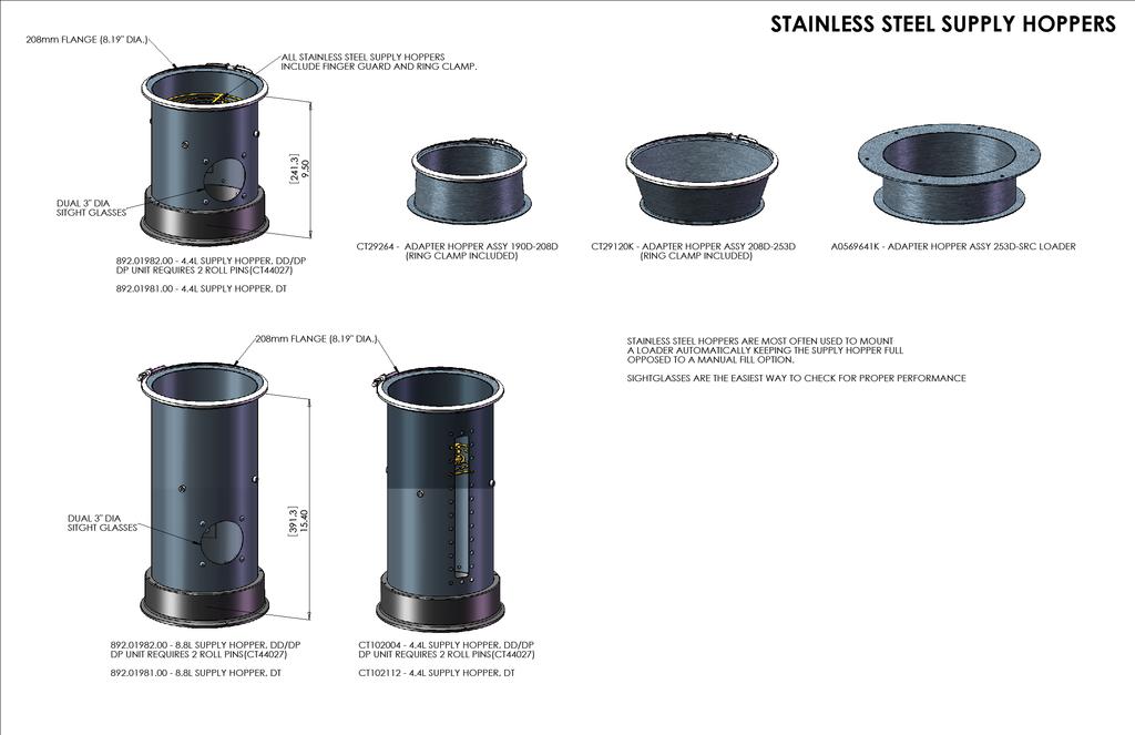
70 Virgin Material Supply Hoppers Various virgin material supply hopper options are available if your existing hopper will not work properly with the Digital Dosing feeder. Contact the Sales Department at for more information. 70 of 96


71 Chapter 4: Maintenance 4-1 Preventative Maintenance Intervals Daily: Weekly: Every 3 months: Every 6 months: Annually: Each time after material Is changed: Check warning signs on equipment for good legibility and completeness. Check function of the On/Off Switch. Check shear plate and mounting hardware in DD dosing station. Check wiper and mounting hardware in DT dosing station. Check that all electrical and mechanical connections are tight. Check adjustment of the level probes (optional). Check dosing disc in dosing station DD and DT. Clean the dosing station. Check shear plate or wiper. Check dosing disc. Always disconnect power and remove the dosing module from the motor assembly before taking the dosing module apart. Injury could result if fingers are pinched between the rotating disc. 71 of 96

72 DD Dosing Module - Pellets 72 of 96
 on the dosing hopper. 7. Remove the dosing hopper from the dosing feeder. 8.")
73 4-2 Removing the Shear Plate ( DD dosing Module) Removing the shear Figure 1. Turn Off off the On/Off switch. 2. Disconnect the power supply. 3. Open the toggle latches on the dosing motor. 4. Remove the dosing unit from the dosing motor. 5. Empty the dosing station. 6. Open the profile clamp (B) on the dosing hopper. 7. Remove the dosing hopper from the dosing feeder. 8. Loosen the two screws (C) on the underside of the dosing unit housing (E). 9. Remove the shear (A). Installing the shear 1. Place the new shear in the dosing unit housing, and ensure that it is positioned correctly. 2. Bolt the shear in place with the two (2) hexagon M5 x 16 socket screws and lock washers. 3. Turn the dosing disc to verify smooth rotation. Replace shear if it is dragging on disc when disc is rotated. 4. Position the dosing hopper on the dosing module, and install the profile clamp (B). 5. Tighten the M10 hex head screw on the profile clamp. 6. Position the dosing unit on the dosing motor, aligning the guide pins. 7. Close the toggle latches, fastening the dosing module to the motor assembly. 73 of 96

74 4-3 Removing the DD Disc and Cleaning the Dosing Module Dismantling the Dosing Module 1. Switch the control unit Off with the On/Off switch. 2. Disconnect the power supply. 3. Open the toggle latches on the dosing motor. 4. Remove the dosing unit from the dosing motor. 5. Empty the dosing module. 6. Open the profile clamp on the dosing hopper. 7. Remove the dosing hopper from the dosing module. 8. Dismantle the dosing module and remove the shear (D) as described above in Loosen and remove the two M6 x 30 socket screws (C) on top of the dosing disc (A). 10. Remove the center M6 x 12 socket screw (B) and replace with an M6 x 30 or 60 screw. 11. Lift the dosing disc (A) from the dosing unit housing (B) by tightening this screw. 12. Clean the shear plate with a cotton cloth. 13. Clean the dosing hopper and the dosing disc in soapy water. 14. The dosing unit housing may also be cleaned with a soft cloth, keeping liquids out of the bearings. 74 of 96
75 Installing the Dosing Module 1. Remove the screw (M6 x 30 or 60) from the center hole. 2. Place the dosing disc in the dosing unit housing. 3. Screw the dosing disc in place with two (2) M6 x 30 socket screws, ensuring they are tight. 4. Re-install the center M6 x 12 socket screw to prevent pellets from getting stuck in the hole. 5. Install the shear, verifying that the fasteners are tight. 6. Turn the dosing disc to verify smooth rotation. If the disc drags on the shear, the shear may have to be loosened and re-positioned, or replaced. 7. Position the hopper on the dosing module. 8. Tighten the profile clamp. 9. Position the dosing unit on the dosing motor, aligning the guide pins. 10. Close the toggle latches, fastening the dosing module to the motor assembly. Installing Different Types of Dosing Discs Dosing discs of the same type, and thickness (except 72 pocket), may be exchanged for each other. If dosing discs with a different compartment number or thickness are installed, the new calibration number needs to be entered into the controller! 1. Enter the (preliminary) calibration value of the newly installed dosing disc 2. Repeat the calibration procedure to determine the final calibration value. See Appendix D: Spare Parts List on page 61 for disc part numbers. 75 of 96

76 DT Dosing Module - Pellets and Some Regrind 76 of 96
77 4-4 Removing/Replacing the Wiper in the DT Dosing Station 1. Switch the control unit Off with the On/Off switch. 2. Disconnect the power supply. 3. Empty the dosing station. 4. Open the toggle latches on the dosing motor. 5. Remove the dosing unit from the dosing motor. 6. Open the profile clamp (C) of the dosing container. 7. Remove the profile clamp (C). 8. Remove the dosing module (A and B). 9. Loosen the 3 plastic screws on the wiper. 10. Remove the wiper and holding plate. 11. Install the new wiper along with the holding plate. 12. Tighten down the 3 plastic screws. Make sure that the wiper is fitted parallel to the dosing plate (Use only plastic screws to avoid damage to the extruder or molding machine screw should the mounting screws ever come loose.) 13. Install the dosing hopper on the dosing housing, ensuring the guide pin is in place, and locate the shelf above the module discharge hole. 14. Install and tighten the profile clamp. 77 of 96
78 4-5 Removing the DT Disc and cleaning the dosing station 1. Switch the control unit Off with the On/Off switch. 2. Disconnect the power supply. 3. Open the toggle latches. 4. Remove the dosing hopper (D) from the motor. 5. Empty the dosing station. 6. Open the profile clamp (C). 7. Remove the profile clamp (C). 8. Remove the dosing hopper assembly (A and B). 9. Remove the two M6 x 30 socket screws (B) on top of the dosing disc (A). Lift the dosing disc (A) from the dosing unit housing. 10. Clean the components with a cotton cloth. 11. Clean the dosing hopper (A and B) in soapy water. 12. Dry all parts thoroughly. 13. Install the dosing hopper on the dosing module (locating the guide pin). 14. Install the profile clamp and tighten the screw. 15. Mount the dosing housing onto the dosing motor. 16. Close the toggle latches, securing the dosing module to the motor assembly. 78 of 96

79 DP Powder Dosing Module 79 of 96
 of the dosing container. 7. Remove the profile clamp (C). 8.")
. 13. Rotate the wiper clockwise, while the metering disc in place. 14.")
80 4-6 Removing/Replacing the DT Disc & Cleaning the Dosing Station 1. Switch the control unit Off with the On/Off switch. 2. Disconnect the power supply. 3. Empty the dosing station. 4. Open the toggle latches on the dosing motor. 5. Remove the dosing unit from the dosing motor. 6. Open the profile clamp (C) of the dosing container. 7. Remove the profile clamp (C). 8. Remove the dosing module (A and B). 9. Hold disc and rotate the wiper 10. counterclockwise (looking at the disc from the top). 11. Remove the wiper and traverse (holding plate). 12. Install the new wiper along with the traverse (holding plate). 13. Rotate the wiper clockwise, while the metering disc in place. 14. Install the dosing hopper on the dosing housing, ensuring the guide pin is in place, 15. and locate the shelf above the module discharge hole. 16. Install and tighten the profile clamp 80 of 96
81 4-7 Removing the DP Disc and Cleaning the Dosing Station 1. Turn the control unit Off. 2. Disconnect the power supply. 3. Open the toggle latches. 4. Remove the dosing hopper (D). 5. Empty the dosing station. 6. Remove the profile clamp (C). 7. Remove the dosing hopper assembly (A and B). 8. Remove the wiper and traverse as described above. 9. Remove the four screws from the metering disc and lift the disc from the dosing unit housing. 10. Clean the components with a cotton cloth. 11. Clean the dosing hopper (A and B) in soapy water. 12. Dry all parts thoroughly. 13. Install the dosing hopper on the dosing module (locating the guide pin). 14. Install the profile clamp and tighten the screw. 15. Mount the dosing housing onto the dosing motor. 16. Close the toggle latches, securing the dosing module to the motor assembly. 81 of 96
82 4-8 Exchangeable Dosing Modules Dosing discs of the same type, i.e. DD may be exchanged for each other. (The 72 pocket also requires a different shear plate.) If dosing discs with a different compartment number are installed, the new calibration number needs to be entered into the controller! 2. Enter the preliminary calibration value of the new dosing disc or module. 3. Repeat the Calibration procedure to determine the final calibration value. DD Discs Disc Calibration Number Number of pockets DD DD DD DD DT Discs Disc Calibration Number Number of Pockets DT DT Sure-shot Oval DT DT DP Discs Disc Calibration Number Number of Disc Thickness Pockets DP mm DP mm 82 of 96

83 4-9 Spare Parts DD Dosing Units ITEM PART NO QTY U/M DESCRIPTION 1 CT EA CALIBRATION BOX CDD CB/SB FIN 2 CT EA DISC HSG DD30 MACH & HARDCOAT 3 CT EA DRIVE CALIBRATION BOX CDD 4 CT EA HOOK FOR DESTACO CLAMP 5 CT EA COVER CALIBRATION BOX CDK/CDD 6 CT EA GASKET COVER CAL BOX CDK/CDD 7 CT EA SHEAR CDD 1.0 CBQ/SB 8 CT EA V-CLAMP DT30 DISC/INTERMEDIATE 9 CT EA DISC DD30, 40 POCKET 10 CT EA BEARING DOUBLE ROW CDDd40; D80; B CT EA SCREW PAN PHILLIPS M4X12 12 CT EA SCREW SOCKET M6X16 13 CT EA SCREW SOCKET M4X40 14 CT EA SCREW SOCKET M6X30 15 CT EA SCREW, M6X10 16 CT EA SCREW SOCKET M5X16 17 CT EA WASHER LOCK M5 18 CT EA DISC DD30, 72 POCKET 19 CT EA DISC DD30, 25 POCKET 20 CT EA DISC DD30, 18POCKET 21 CT EA SHEAR DD, 72 POCKET, 3MM 22 CT EA TRAY CAL BOX 23 CT EA ALL OTHER DISCS, 5MM 83 of 96

84 DT Dosing Units ITEM PART NO QTY U/M DESCRIPTION 1 CT EA DISC HOUSING DT30 10MM 2 CT EA HOOK FOR DESTACO CLAMP 3 CT EA BEARING RSR 4 CT EA DISC DT30, 20 POCKET 5 CT EA COUPLING DRIVE CBQ/SB 6 CT EA V-CLAMP DT30 DISC/INTERMEDIATE 7 CT EA RETAINING RING 80X2.5 8 CT EA SCREW PAN PHILLIPS M4X12 9 CT EA MOUNT CALIBRATE TUBE CDK/CB/SB 10 CT EA SCREW HEX M6X35 11 CT EA WASHER FLAT M6 12 CT EA SCREW SOCKET M5X16 13 CT EA WASHER FLAT M5 14 CT EA CALIBRATION TUBE CDK/CB/SB 15 CT EA DISC DT30, 20 POCKET, SURE SHOT 16 CT EA DISC DT30 12 POCKET 20MM DEEP 17 CT EA DISC DT30 1O POCKET, 20MM DEEP 18 CT EA SCREW HEX M6X35 19 CT EA DISC HOUSING DT30 20MM 84 of 96

85 DP Dosing Units ITEM PART NO QTY U/M DESCRIPTION EA DISK, HSG, TIGHT TOL, DP30 2 CT EA HOOK FOR DESTACO CLAMP 3 CT EA BEARING RSR 4 CT EA RETAINING RING 80X2.5 5 CT EA DISC METERING DP30-5 NYLON 6 CT EA HUB K1DP DISK KCT EA TRAVERST, TIGHT TOL 5MM, DP30 8 CT EA BEARING 626 2RS D6X19X6 9 CT EA BEARING RS 10X26X EA DISK, EJECT, TIGHT TOL, DP30, 5MM 11 CT EA BUSHING DISC EJECTION DP CT EA WIPER BLADE DP CT EA AGITATOR DP30 W/SAIL 14 CT EA SEAL V22A DP30/DP50 15 CT EA COUPLING DRIVE DP30 (E) 16 CT EA SCREW PAN PHILLIPS M4X12 17 CT EA SCREW SOCKET M6X20 18 CT EA SCREW SOCKET FLAT M6X16 19 CT EA CALIBRATION BOX DT30/DP30 FIN 20 CT EA RETAINING RING 50X2 21 CT EA GASKET COVER CAL BOX CDK/CDD 22 CT EA COVER CALIBRATION BOX CDK/CDD 23 CT EA SCREW SOCKET M6X16 24 CT EA SCREW SOCKET M4X40 25 CT EA WIPER BLADE DP CT EA DISC METERING DP NYLON 27 CT EA DISK, EJECT, TIGHT TOL, 5MM DP30 28 CT EA BUSHING DISC EJECTION DP EA TRAVERSE, TIGHT TOL, 5MM, DP30 30 CT EA DRIVE CALIBRATION BOX CDK 31 CT EA DP30, STANDARD AGITATOR 32 CT EA TRAY CAL BOX 85 of 96

86 DD/DT/DP Additional Spare Parts ITEM PART NO QTY U/M DESCRIPTION EA COVER WITH KNOB, SS FOR ACRYLIC HOPPER EA ACRYLIC HOPPER, 4.4 LITER, ACRYLIC ONLY EA ACRYLIC HOPPER, 8.8 LITER, ACRYLIC ONLY EA KIT, HANDLE, DD/DT/DP, SUPPLY HOPPER 5 CT EA V-CLAMP DD/DT/TP, HOPPER TO DISK HOUSING 6 CT EA HOOK FOR TOGGLE CLAMP 7 CT EA TOGGLE LATCH 8 CT EA DOSING MOTOR ASSEMBLY,38 RPM 9 CT EA DOSING MOTOR ASSEMBLY, 11.5 RPM 10 CT EA DOSING MOTOR ASSEMBLY, 8.4 RPM EA DOSING MOTOR ASSEMBLY, 3 RPM 86 of 96
87 Appendix A Basic Parameter Settings A-2 Recipe Formulas The following formulas can be used to determine if a recipe is appropriate or possible. Injection Molding For injection molding applications, compute the dosing disc speed and total number of disc revolutions using the following formulas. Recipe limitations are listed in the table following the equations. Recipe Limitations for Injection Molding Motor Speed (rpm) Maximum Max Speed (rpm) Min Speed (rpm) Extrusion - Simple For extrusion applications, compute the dosing disc speed using the following formula. Recipe limitations are listed in the table following the recipe. Disc RPM Recipe Limitations Extrusion ( Additive - %) x (Total Extruder Throughput - lb / hr) = x (Disc Calibration Weight - g) Motor Speed (rpm) Maximum Max Speed (rpm) Min Speed (rpm) of 96

88 Appendix B Disc Sizing Guides 88 of 96
89 89 of 96


90 Appendix C Drawings Single Station Digital Dosing Feeder SIDE VIEW TOP VIEW 90 of 96


91 Duo Digital Dosing Feeder SIDE VIEW TOP VIEW 91 of 96

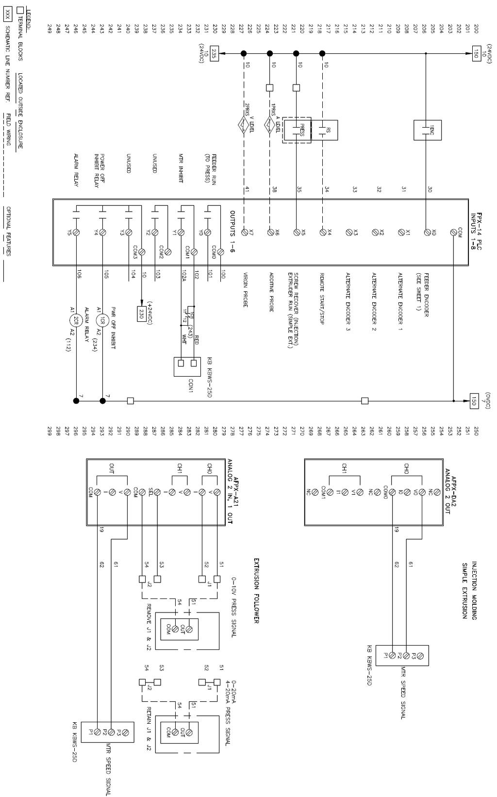
92 Electrical Schematics of A250 Controller 92 of 96
93 93 of 96
TrueBlend Blender. With SB-3 Control U S E R G U I D E UGB
 U S E R G U I D E UGB031-0917 www.conairgroup.com TrueBlend Blender With SB-3 Control Corporate Office: 724.584.5500 l Instant Access 24/7 (Parts and Service): 800.458.1960 l Parts and Service: 814.437.6861
COOPER POWER SERIES. Input/Output (I/O) module installation instructions. Voltage Regulators MN225067EN
 module installation instructions. Voltage Regulators MN225067EN") Voltage Regulators MN225067EN Effective November 2016 Supersedes June 2014 (S225-70-13) COOPER POWER Input/Output (I/O) module installation instructions SERIES DISCLAIMER OF WARRANTIES AND LIMITATION OF
Voltage Regulators MN225067EN Effective November 2016 Supersedes June 2014 (S225-70-13) COOPER POWER Input/Output (I/O) module installation instructions SERIES DISCLAIMER OF WARRANTIES AND LIMITATION OF
MAXIMA + Series ROTARY LEVEL CONTROL
 Price $5.00 MAXIMA + Series ROTARY LEVEL CONTROL OPERATING INSTRUCTIONS PLEASE READ CAREFULLY Division of Garner Industries 7201 North 98th Street Lincoln, NE 68507-9741 (402) 434-9102 925-0268 Rev. A
MAXIMA+ Series Rotary Level Indicator
 MAXIMA+ Series Rotary Level Indicator BinMaster: Division of Garner Industries 7201 N. 98th St., Lincoln, NE 68507 402-434-9102 email: info@binmaster.com www.binmaster.com OPERATING INSTRUCTIONS PLEASE
Resolver to Digital Expansion Board
 Resolver to Digital Expansion Board Catalog No. EXB009A01 Installation and Operating Manual 6/98 MN1313 Table of Contents Section 1 General Information............................. 1-1 Introduction....................................
WEIGH SCALE BLENDER WITH FOUR COMPONENT SOFTWARE SEPTEMBER 04, 2002 TUTORIAL MANUAL
 Maguire Products Inc Maguire Products Inc Maguire Products Inc Maguire Products Inc Maguire Products Inc Maguire Products Inc Maguire Products Inc Eleven Crozerville Road Aston, PA. 610 459-4300 WEIGH
COOPER POWER SERIES. RS-485 digital communications accessory board installation and operation instructions. Voltage Regulators MN225074EN
 Voltage Regulators MN225074EN Effective March 2017 Supersedes January 2012 (S225-40-7) RS-485 digital communications accessory board installation and operation instructions COOPER POWER SERIES DISCLAIMER
MGF-ST Gravimetric Feeders
 Throughput capacity up to 120 lb/hr (55 Kg/hr) for continuous extrusion and 40 lb/hr (18 Kg/hr) for injection molding. * Based on 55 lb/ft 3 bulk density MGF-ST Gravimetric Feeders Gravimetric feeder for
Model P4017 Single Channel USB Oscilloscope. Quick Start Guide
 Model P4017 Single Channel USB Oscilloscope Quick Start Guide General Warranty BNC warrants that the product will be free from defects in materials and workmanship for 3 years from the date of purchase
KBMG MULTI-SPEED BOARD
 TM INSTALLATION AND OPERATION MANUAL KBMG MULTI-SPEED BOARD KB Part No. 8833 Multi-Speed Board for KBMG Series Regenerative Drive Pending! See Safety Warning on Page 1 The information contained in this
Vapor Monitor Interface Module
 Manual No: 577013-951 Revision: A Vapor Monitor Interface Module Installation Guide Notice Veeder-Root makes no warranty of any kind with regard to this publication, including, but not limited to, the
Operating Instructions & Service Manual FOULS
 FOULS Operating Instructions & Service Manual FOULS Basketball Player Fouls Panels Model MP-5215 EFFECTIVE S.N. 17,100, June 18, 2001 TABLE OF CONTENTS PAGE 1. GENERAL INFORMATION 3 1.1 DESCRIPTION 1.2
CBT LW 4-PUMP ADD-ON INTERNATIONAL INSTALLATION GUIDE
 CBT LW 4-PUMP ADD-ON INTERNATIONAL INSTALLATION GUIDE 2 General information This manual contains technical information regarding Bayer SeedGrowth Equipment. Please read and understand these instructions
DIGITAL GEAR PUMP DRIVE OPERATING MANUAL: Model No.
 OPERATING MANUAL: DIGITAL GEAR PUMP DRIVE Model No. 75211-70 Digital Gear Pump Drive 75211-70 A-1299-1142 Edition 01 Cole-Parmer 1-800-323-4340 ((U.S. and Canada only) 11 (847) 549-7600 (Outside U.S.)
Ratio Feeder Series J+ Advanced Pumper Controller
 UNPACKING Figure 1 J Plus Controller Please open and inspect your package upon receipt. Your package was packed with great care and all the necessary packing materials to arrive to you undamaged. If you
Type VR Electrically Operated Ground and Test Device
 Type VR Electrically Operated Ground and Test Device For Use with Masterclad Switchgear 4.76 kv 15 kv, 1200, 2000, 3000, 4000 A Up to 63 ka Short Circuit Rating Class 6055 Instruction Bulletin 6055-37
NOVATEC/MAGUIRE Blender Selection Guide
 NOVATEC/MAGUIRE Blender Selection Guide The most popular blenders worldwide Three out of four gravimetric blenders purchased are manufactured by Maguire Products and NOVATEC is proud to be the world's
MODEL SST3-MV INSTALLATION INSTRUCTIONS FOR FEDERAL MODEL SST3-MV SELECTABLE SIRENTONE-MULTI VOLT
 MODEL INSTALLATION INSTRUCTIONS FOR FEDERAL MODEL SELECTABLE SIRENTONE-MULTI VOLT INSTALLATION INSTRUCTIONS FOR FEDERAL MODEL SELECTABLE SIRENTONE-MULTI VOLT A. GENERAL. The Federal Model is a solid-state
Series Amp Pad Mount Quick Connect Input and Output Power Panels
 Series 300 2000-4000 Amp Pad Mount Quick Connect Input and Output Power Panels DANGER is used in this manual to warn of a hazard situation which, if not avoided, will result in death or serious injury.
USER MANUAL VIBRATION CONTROL RMA-POWER-BOX 107/230
 USER MANUAL VIBRATION CONTROL Version 2.2 1 IMPORTANT NOTES Electrical danger within the meaning of this documentation or the warning labels on the product itself respectively means that death, serious
EPS Power Supply
 EPS - 600 Power Supply Installation and Operation Manual Version 1.0 *This instrument is intended for laboratory use only Index A. Important Notice ----------------------------------------------------------------
Operation Manual MODEL 2TX. 2-wire Isolated ph/orp Transmitter
 Operation Manual MODEL 2TX 2-wire Isolated ph/orp Transmitter 0 2TX CONTENTS INITIAL INSPECTION.....2 INTRODUCTION......2 ASSEMBLY...3 PREPARATION....4 CONNECTING THE ELECTRODE...4 CONNECTING THE TEMPERATURE
MGF-ST Series Gravimetric Feeder
 MGF-ST Series Gravimetric Feeder OVERVIEW Overview of our Maguire WSB Feeder Range HOW IT WORKS Simple, accurate, affordable and easy to use PRODUCT INFORMATION View our full technical specification and
OPERATING INSTRUCTIONS AND SERVICE MANUAL BASKETBALL SHOTCLOCK MODEL MP-5299
 OPERATING INSTRUCTIONS AND SERVICE MANUAL BASKETBALL SHOTCLOCK MODEL MP-5299 EFFECTIVE S.N. 17,000, December, 2000 TABLE OF CONTENTS 1. General Information 1.1 Description 1.2 Identification 1.3 Damage
COOPER POWER SERIES. 600 A U-OP visible break connector system operation instructions. Deadbreak Apparatus Connectors MN650022EN
 Deadbreak Apparatus Connectors MN650022EN COOPER POWER Effective March 2016 Supersedes S600-14-1 June 2010 SERIES 600 A U-OP visible break connector system operation instructions DISCLAIMER OF WARRANTIES
NETRONICS HS3500 CONTROLLER
 NETRONICS HS3500 CONTROLLER CUSTOMER NAME CONTROLLER SERIAL # CONTROLLER PART # PERSONALITY SWITCH SETTINGS BULLET PRESS CONFIGURATION DELIVERY DATE Contact the factory for help setting up your application.
Installation Instructions
 50ES, 50EZ, 50GL, 50GS, 50GX, 50JS, 50JX, 50JZ, 50SD, 50SZ, 50VL, 50VT, 50XP, 50XZ 601A, 602A, 602B, 604A, 604B, 604D, 607C, 701A, 702A, 702B, 704A, 704B, 704D, 707C PA1P, PA2P, PA3P, PH1P, PH2P, PH3P
MAXIMA + Series ROTARY LEVEL CONTROL
 Price $5.00 MAXIMA + Series ROTARY LEVEL CONTROL OPERATING INSTRUCTIONS PLEASE READ CAREFULLY Division of Garner Industries 7201 North 98th Street Lincoln, NE 68507-9741 (402) 434-9102 925-0268 TABLE OF
180 DEGREE PEEL TESTER
 180 DEGREE PEEL TESTER MODEL PA-1000-180 OPERATING INSTRUCTIONS CHEMINSTRUMENTS 510 COMMERCIAL DRIVE FAIRFIELD, OHIO 45014 (513) 860-1598 www.cheminstruments.com Revision 1.1 August 7, 2017 CONTENTS PRODUCT
GV3000/SE Operator Interface Module (OIM) User Guide Version 2.0 M/N 2RK3000
 User Guide Version 2.0 M/N 2RK3000") GV3000/SE Operator Interface Module (OIM) User Guide Version 2.0 M/N 2RK3000 Instruction Manual D2-3342-2 The information in this manual is subject to change without notice. Throughout this manual, the
GV3000/SE Operator Interface Module (OIM) User Guide Version 2.0 M/N 2RK3000 Instruction Manual D2-3342-2 The information in this manual is subject to change without notice. Throughout this manual, the
OPERATING AND SERVICE MANUAL. Universal Interface Device 47
 OPERATING AND SERVICE MANUAL Universal Interface Device 47 MAGNA-POWER ELECTRONICS, INC. 39 ROYAL ROAD, FLEMINGTON, NJ 08822 May 24, 2012 SAFETY NOTICE Universal Interface Device 47 (UID46) connects
Analog Monitor Installation Manual
 Analog Monitor Installation Manual Part Number: 144-23919 Copyright 2011 Magnetek 1. Preface and Safety Magnetek manufactures products used as components in a wide variety of industrial systems and equipment.
DM-918 OPERATIONS MANUAL AUTORANGING MULTIMETER
 DM-918 OPERATIONS MANUAL AUTORANGING MULTIMETER SAFETY INFORMATION The following safety information must be observed to ensure maximum personal safety during the operation of this meter: This meter is
Operation Manual. Concorde 600 Power Supply. *This instrument is intended for laboratory use only.
 Concorde 600 Power Supply Operation Manual Cat.no. R10-1001011 *This instrument is intended for laboratory use only http://www.recenttec.com E-mail : support@recenttec.com Version 1.1 Packing List x 1
Torque Series LCD Remote Panel Installation/Operation Manual Model: TQ-DSP-12/24
 Torque Series LCD Remote Panel Installation/Operation Manual Model: TQ-DSP-12/24 Section Page Introduction 1 Materials Provided 1 I) Safety Instructions 1 A) Inverter Safety Instructions 1 B) Battery Safety
TD2100 Electric Gummed Tape Dispenser Owner s Manual
 TD2100 Electric Gummed Tape Dispenser Owner s Manual Marsh Shipping Supply Co. LLC 926 McDonough Lake Road Collinsville, IL 62234 www.msscllc.com Customer Service Phone: (618)-343-1006 Fax: (618)-343-1016
D-Pack 6 Classic ORDERCODE 50315
 D-Pack 6 Classic ORDERCODE 50315 Congratulations! You have bought a great, innovative product from Showtec. The Showtec D-Pack 6 Classic brings excitement to any venue. Whether you want simple plug-&-play
SPECIAL INSTRUCTIONS FOR CAPACITORS COMPACT GENERATORS
 SPECIAL INSTRUCTIONS FOR CAPACITORS COMPACT GENERATORS (WITH CAPACITOR CHARGER BOARD A3517-02) The process depends on Generator and System configuration. This document applies to installation of Capacitors
Analog Input Installation Manual
 Analog Input Installation Manual August 2011 Part Number: 144-23917 Copyright 2011 Magnetek 1. Preface and Safety Magnetek manufactures products used as components in a wide variety of industrial systems
LiquiFlo AC General Purpose (Volts/Hertz) and Vector Duty Drive Software Start-Up and Reference Manual Version 6.4
 and Vector Duty Drive Software Start-Up and Reference Manual Version 6.4") LiquiFlo AC General Purpose (Volts/Hertz) and Vector Duty Drive Software Start-Up and Reference Manual Version 6.4 Instruction Manual D2-3410-7 The information in this manual is subject to change without
LiquiFlo AC General Purpose (Volts/Hertz) and Vector Duty Drive Software Start-Up and Reference Manual Version 6.4 Instruction Manual D2-3410-7 The information in this manual is subject to change without
Instruction Manual. Electrical Management System (EMS) EMS-HW30C & EMS-HW50C
 EMS-HW30C & EMS-HW50C") Instruction Manual Electrical Management System (EMS) EMS-HW30C & EMS-HW50C EMS-HW50C EMS-HW30C! CAUTION These instructions are intended to provide assistance with the installation of this product, and
Instruction Manual Electrical Management System (EMS) EMS-HW30C & EMS-HW50C EMS-HW50C EMS-HW30C! CAUTION These instructions are intended to provide assistance with the installation of this product, and
PDS100 Programmable Dispensing System SAFETY INSTRUCTIONS
 PDS100 Programmable Dispensing System INSTRUCTION MANUAL SAFETY INSTRUCTIONS Before using any Fluid Metering, Inc. product read the following safety instructions as well as specific product specifications
Installation and Operation Back-UPS BR1000G-IN / BR1500G-IN
 Installation and Operation Back-UPS BR1000G-IN / BR1500G-IN Important Safety Information Read the instructions carefully to become familiar with the equipment before trying to install, operate, service
MBE Mounts and Adapters
 MBE Mounts and Adapters MBE Series en Installation Guide MBE Mounts and Adapters Table of Contents en 3 Table of Contents 1 Important safety instructions 4 2 MBE Series Mounts and Adapters 6 2.1 Unpacking
BS 181 SINGLE CHANNEL POWER SUPPLY USER MANUAL
 BS 181 SINGLE CHANNEL POWER SUPPLY USER MANUAL Issue 2011 ASL Intercom BV DESIGNED & MANUFACTURED BY: ASL Intercom B.V. Zonnebaan 42 3542 EG Utrecht The Netherlands Tel: +31 (0)30 2411901 Fax: +31 (0)30
KIP Certified AutoCAD Driver. KIPFold 2800 User Guide Version SN 1.0
 KIP Certified AutoCAD Driver KIPFold 2800 User Guide Version SN 1.0 Safety Read these safety instructions completely before operating the folder and keep this manual for future reference close to the folder.
TLS-3XX Series Consoles
 Manual No: 0-0 Revision: A TLS-XX Series Consoles Display Replacement Guide Notice Veeder-Root makes no warranty of any kind with regard to this publication, including, but not limited to, the implied
Gravimetric Batch Blending With Extrusion Yield Control
 Gravimetric Batch Blending With Extrusion Yield Control TrueBlend EXT TM Extrusion Control Blenders combine precision gravimetric batch blending with extrusion yield monitoring or control to provide the
LINE VOLTAGE TESTER CT101 USER S MANUAL. Please read this manual carefully and thoroughly before using this product.
 LINE VOLTAGE TESTER USER S MANUAL CT101 Please read this manual carefully and thoroughly before using this product. KEY FEATURES Visual indication of AC or DC voltage Easy to use approved Safe for CAT
PHASETRONICS. SCR Power Control Specialists. EP1 Series Power Control Single Phase SCR Amps OPERATION & SERVICE MANUAL
 PHASETRONICS Specialists EP1 Series Power Control Single Phase SCR 10-50 Amps OPERATION & SERVICE MANUAL Phasetronics, Inc. P.O. Box 5988 1600 Sunshine Drive Clearwater, FL 33765 (727)573-1900 FAX(727)573-1803
Progressive Industries, Inc. EMS Electrical Management System
 Progressive Industries, Inc. EMS Electrical Management System Complete Installation Guide and Operating Instructions for: Model EMS-LCHW50 Rated at 240V/50A Manufactured by: Progressive Industries, Inc.
OPERATING AND SERVICE MANUAL. Universal Interface Device 47
 OPERATING AND SERVICE MANUAL Universal Interface Device 47 MAGNA-POWER ELECTRONICS, INC. 39 ROYAL ROAD, FLEMINGTON, NJ 08822 May 24, 202 SAFETY NOTICE Universal Interface Device 47 (UID47) connects two
GV3000/SE General Purpose (Volts/Hertz) and Vector Duty AC Drive, HP, 230V AC
 and Vector Duty AC Drive, HP, 230V AC") Software Start-Up and Reference Manual D2-3416-2 GV3000/SE General Purpose (Volts/Hertz) and Vector Duty AC Drive, 30-100 HP, 230V AC Version 6.04 Important User Information Solid-state equipment has operational
Software Start-Up and Reference Manual D2-3416-2 GV3000/SE General Purpose (Volts/Hertz) and Vector Duty AC Drive, 30-100 HP, 230V AC Version 6.04 Important User Information Solid-state equipment has operational
Model 2460-KIT. Screw Terminal Connector Kit. Description / September 2014 *P * 1
 Keithley Instruments 28775 Aurora Road Cleveland, Ohio 44139 1-800-935-5595 http://www.keithley.com Model 2460-KIT Screw Terminal Connector Kit Description The Model 2460-KIT Screw Terminal Connector Kit
Product Description. S&C 5800 Series Automatic Switch Control S&C ELECTRIC COMPANY TABLE OF CONTENTS
 S&C 5800 Series Automatic Switch Control Product Description TABLE OF CONTENTS Section Page INTRODUCTION Qualified Persons............................... 2 Read this Instruction Sheet.......................
Revo 120. User Manual
 Revo 120 User Manual GENERAL INFORMATION Congratulations, you have just purchased one of the most innovative and reliable lighting fixtures on the market today! The Revo 120 has been designed to perform
INSTALLATION INSTRUCTIONS STZ-R SERIES (ENGLISH)
") Surge-Trap STZ-R series Surge Protective Device (SPD) Danger Hazard of Electrical Shock, Explosion or Arc Flash Only qualified licensed electricians should install or service SPDs Verify that all power
Surge-Trap STZ-R series Surge Protective Device (SPD) Danger Hazard of Electrical Shock, Explosion or Arc Flash Only qualified licensed electricians should install or service SPDs Verify that all power
PDS8u POWER DISTRIBUTION SYSTEM USER'S MANUAL
 PDS8u POWER DISTRIBUTION SYSTEM USER'S MANUAL 1 IMPORTANT SAFETY INSTRUCTION READ FIRST This symbol, whenever it appears, alerts you to the presence of uninsulated dangerous voltage inside the enclosure-voltage
PS8 - II. Professional Power Sequencer. User s Manual
 PS8 - II Professional Power Sequencer User s Manual IMPORTANT SAFETY INSTRUCTIONS READ FIRST This symbol, whenever it appears, alerts you to the presence of uninsulated dangerous voltage inside the enclosure.
MFA-0801 & MFA-1201 D-M-E Smart Series Low Voltage Temperature Control System. User s Manual. D-M-E Company
 MFA-0801 & MFA-1201 D-M-E Smart Series Low Voltage Temperature Control System User s Manual D-M-E Company D-M-E Company MFA-0801 & MFA-1201 Page 1 Copyright D-M-E Company 1995. All rights reserved. D-M-E
Series Amp Quick Connect Input and Output Power Panels
 Series 300 1200-1600 Amp Quick Connect Input and Output Power Panels DANGER is used in this manual to warn of a hazard situation which, if not avoided, will result in death or serious injury. WARNING is
Electrical Management System (EMS) EMS-HW30C & EMS-HW50C
 EMS-HW30C & EMS-HW50C") Electrical Management System (EMS) EMS-HW30C & EMS-HW50C Installation & Operating Guide for: Model EMS-HW30C Rated at 120V/30A and Model EMS-HW50C Rated at 240V/50A Surgio Says Lifetime Warranty on all
Electrical Management System (EMS) EMS-HW30C & EMS-HW50C Installation & Operating Guide for: Model EMS-HW30C Rated at 120V/30A and Model EMS-HW50C Rated at 240V/50A Surgio Says Lifetime Warranty on all
MIC-3001/8. 3U/4U CompactPCI. Enclosure for Rackmounting
 MIC-3001/8 3U/4U CompactPCI Enclosure for Rackmounting Copyright Notice This document is copyrighted, 1999. All rights are reserved. The original manufacturer reserves the right to make improvements to
90 DEGREE PEEL TESTER
 90 DEGREE PEEL TESTER MODEL PA-1000-90 OPERATING INSTRUCTIONS CHEMINSTRUMENTS 510 COMMERCIAL DRIVE FAIRFIELD, OHIO 45014 (513) 860-1598 www.cheminstruments.com Revision 1.1 August 7, 2017 CONTENTS PRODUCT
Altivar 61/71 Adjustable Speed Drives Heatsink Fan Kits VZ3V1212 and VZ3V1216
 Altivar 61/71 Adjustable Speed Drives Heatsink Fan Kits VZ3V1212 and VZ3V1216 Instruction Bulletin 30072-452-48 Retain for future use. 30072-452-48 Altivar 61/71 Heatsink Fan Kits VZ3V1212 and VZ3V1216
Power Supply (48Vdc, 2.5A)
") Telecommunications Group Section 855-180-201 Equipment Issue 1 Fourth Printing, September 2006 8551-80 Power Supply (48Vdc, 2.5A) Compliant with UL Standard 60950, Second Edition* CONTENTS PAGE Part 1.
Telecommunications Group Section 855-180-201 Equipment Issue 1 Fourth Printing, September 2006 8551-80 Power Supply (48Vdc, 2.5A) Compliant with UL Standard 60950, Second Edition* CONTENTS PAGE Part 1.
OPERATION MANUAL MODEL TT-LP
 TURTLE TOUGH OPERATION MANUAL MODEL TT-LP 2-Wire Isolated ph/orp Transmitter turtletough.com.au CONTENT INITIAL INSPECTION 3 INTRODUCTION 3 ASSEMBLY 4 PREPARATION 5 Connection Diagram of Turtle Tough Sensors
GV3000/SE 230 VAC 1-20 HP General Purpose (Volts/Hertz) and Vector Duty Drive Software Start-Up and Reference Manual Version 6.04
 and Vector Duty Drive Software Start-Up and Reference Manual Version 6.04") GV3000/SE 230 VAC 1-20 HP General Purpose (Volts/Hertz) and Vector Duty Drive Software Start-Up and Reference Manual Version 6.04 Instruction Manual D2-3387-4 The information in this manual is subject
GV3000/SE 230 VAC 1-20 HP General Purpose (Volts/Hertz) and Vector Duty Drive Software Start-Up and Reference Manual Version 6.04 Instruction Manual D2-3387-4 The information in this manual is subject
TOT Series Manual. North American CE and UK Models. CE Models. UK Models. North American Models
 TOT Series Manual North American CE and UK Models CE Models UK Models North American Models Table of Content 1. Important Safety Instructions 2. Description Shipping Carton & Packing Material Placement
OPERATING INSTRUCTIONS AND SERVICE MANUAL BASEBALL SCOREBOARD MODEL MP-3350 WITH MP-2002 CONTROL
 OPERATING INSTRUCTIONS AND SERVICE MANUAL BASEBALL SCOREBOARD MODEL MP-3350 WITH MP-2002 CONTROL EFFECTIVE S.N. XXXX JAN 1, 1993 1 1. General Information TABLE OF CONTENTS 1.1 Description 1.2 Identification
DIGITAL VOLTAGE INDICATOR
 DIGITAL VOLTAGE INDICATOR Instruction Manual US Patent 6,998,832 HD ELECTRIC COMPANY 1475 LAKESIDE DRIVE WAUKEGAN, ILLINOIS 60085 U.S.A. PHONE 847.473.4980 FAX 847.473.4981 website: www.hdelectriccompany.com
This document hosted by: Ranger 7000 Scales Instruction Manual
 This document hosted by: www.oldwillknottscales.com Ranger 7000 Scales Instruction Manual RANGER 7000 SCALES EN-1 TABLE OF CONTENTS 1 INTRODUCTION...4 1.1 Description... 4 1.2 Features... 4 1.3 Definition
ABM International, Inc. Lightning Stitch Checklist 9/13/2013
 ABM International, Inc. Lightning Stitch Checklist 9/13/2013 1) Piggy backed board assembly (1) Piggy back board assembly tested? Yes No 24v passed XB passed XA passed YB passed YA passed SAFE passed S/S
Install Motor Controller User Manual
 Property of Motion Laboratories, Inc. Install Motor Controller User Manual 2014 Motion Laboratories, Inc. Created By: Michael Shaw Approved By: John Coppolecchia Page: 1 Page: 2 2014 Motion Laboratories,
Secured Series: Hub Plus Kit Single Door Controller Package Installation Manual
 Secured Series: Hub Plus Kit Single Door Controller Package Installation Manual This package is designed to simplify the connections to our Secured Series Hub Plus Controller. This will translate into
EMS. Electrical Management System. Progressive Industries Incorporated Morrisville, North Carolina
 Progressive Industries Warranty Progressive warrants its products are free from defects in materials and workmanship for a period of three years. This is in lieu of all other warranties, obligations, or
Service Instructions. Conductor 420
 Service Instructions Conductor 420 Listed, File No. E195547 Input: 480 VAC, 50/60 HZ. (Operating range 380-480 VAC) 20 AMP MAX OUTPUT W/25 AMP FUSE Output: 0-90% of Input Voltage Table of Contents General
EQUIPMENT OPERATION MANUAL
 EQUIPMENT OPERATION MANUAL Loctite S440 Series SCARA Robots Book 2 of 4: Quick Start A Company FOR SAFE USE Safety Notes Read the following Warnings and Cautions thoroughly for the safe use of the Scara
This 4200-RM Rack Mount Kit is for installation in 4200-CAB series cabinets only.
 Keithley Instruments, Inc. 28775 Aurora Road Cleveland, Ohio 44139 (440) 248-0400 Fax: (440) 248-6168 www.keithley.com Model 4200-RM Rack Mount Kit Packing List Introduction NOTE This 4200-RM Rack Mount
TOT Series Manual. North American and International Models - without optional faceplate. Receptacle Panel of International Models, CE model shown
 TOT Series Manual North American and International Models - without optional faceplate Receptacle Panel of International Models, CE model shown North American Models Table of Content 1. Important Safety
CubePro. Main PCB Replacement Guide. Prosumer 3D Printer. Original Instructions
 CubePro Prosumer 3D Printer Main PCB Replacement Guide Original Instructions 1 INTRODUCTION COPYRIGHT 2014 by All rights reserved. This document is subject to change without notice. This document is copyrighted
DCM Digital Control Modules
 DCM Digital Control Modules TECHNICAL MANUAL Version 1.2 November 2011 Safety Precautions Caution Read Instructions: Read and understand all safety and operating instructions before using the equipment.
IS Series Manual. 19 Pro Series Rack Mount (RK) Faceplate. 17 Consumer Series (C) Faceplate Available in Black (B) and Silver (S) colours
 Faceplate. 17 Consumer Series (C) Faceplate Available in Black (B) and Silver (S) colours") IS Series Manual IS O Power IS Series Toroidal Isolation Power Conditioning 19 Pro Series Rack Mount (RK) Faceplate IS O Power IS Series Toroidal Isolation Power Conditioning 17 Consumer Series (C) Faceplate
IS Series Manual IS O Power IS Series Toroidal Isolation Power Conditioning 19 Pro Series Rack Mount (RK) Faceplate IS O Power IS Series Toroidal Isolation Power Conditioning 17 Consumer Series (C) Faceplate
Dell MD1280 Storage Enclosure Getting Started Guide
 Dell MD1280 Storage Enclosure Getting Started Guide Regulatory Model: SP-2584, E11J Notes, Cautions, and Warnings NOTE: A NOTE indicates important information that helps you make better use of your computer.
PS/IO Circuit Board Retrofit
 S&C 6800 Series Automatic Switch Controls PS/IO Circuit Board Retrofit Table of Contents Section Page Introduction Qualified Persons.... 2 Read this Instruction Sheet.... 2 Retain this Instruction Sheet....
Intelligent Channel Bank Shelf
 Telecommunications Group Section 360-080-204 Equipment Issue 4 Third Printing, August 2006 360-80 Intelligent Channel Bank Shelf CONTENTS PAGE Part 1. GENERAL.............................................................................
Operating instructions. Speed monitor D / / 2014
 Operating instructions Speed monitor D200 80005257 / 00 05 / 2014 Contents 1 Preliminary note...4 1.1 Symbols used...4 1.2 Warning signs used...4 2 Safety instructions...5 2.1 General...5 2.2 Target group...5
Electric Actuators and Control Systems. Established Leaders in Valve Actuation AD-8140 & AD Instruction Manual. Publication P971E Issue 08/09
 Electric Actuators and Control Systems Established Leaders in Valve Actuation AD-8140 & AD-8240 Instruction Manual Publication P971E Issue 08/09 Instruction Manual IM-0665 AD-8140 & AD-8240 Digital Servo
Manual Control Unit GFC 32
 Manual Control Unit 1400004_EN/05.2017 Index 1. Main features 3 2. Technical features 3 3. Installation guidelines 4 4. Preliminary checks 5 5. Electrical connections 5 6. Settings 6 7. Remote control
TA18 active subwoofer. user manual
 TA18 active subwoofer user manual Musikhaus Thomann e.k. Treppendorf 30 96138 Burgebrach Germany Telephone: +49 (0) 9546 9223-0 email: info@thomann.de Internet: www.thomann.de 30.11.2011 Table of contents
VK-3iX WARRANTY REGISTRATION FORM
 VK-3iX WARRANTY REGISTRATION FORM Unit Serial Number: Customer Name: Address: Date of Purchase: Purchased From: Dealer Name: Address: IMPORTANT NOTE: In order to receive the full five year product warranty,
120VAC Interface Option Cards for V7/ V74X / GPD315 Drives
 YASKAWA 120VAC Interface Option Cards for V7/ V74X / GPD315 Drives INSTRUCTIONS Upon receipt of the product and prior to initial operation, read these instructions thoroughly, and retain for future reference.
ControlKeeper 4. General Information. Connecting Relay Loads. Installation Sheet. Getting Started. Power Supply Wiring. Mounting the Cabinet
 General Information ControlKeeper 4 Installation Sheet Model# CK4-120NO- Model# CK4-277NO The ControlKeeper-4 model is shipped in one package and is configured with either a 120V or a 277V transformer.
User s Manual. ACS550-PD Stock 3R Irrigation Packaged Drive Supplement to ACS550-U1 User s Manual
 User s Manual ACS550-PD Stock 3R Irrigation Packaged Drive Supplement to ACS550-U1 User s Manual 2 ACS550-PD 3R Irrigation Packaged Drive ACS550 Drive Manuals GENERAL MANUALS ACS550-U1 User s Manual (1
I/O SIGNAL CONDITIONER
 Technical Data Sheet No. TD9809M Rev. F Date of Issue: December 9, 2009 OPERATING MANUAL I/O SIGNAL CONDITIONER CAUTION: THIS PRODUCT DOES NOT PROVIDE GALVANIC ISOLATION. DO NOT ATTEMPT USE OF THIS PRODUCT
User's Guide. MiniTec TM Series Model MN25 MultiMeter
 User's Guide MiniTec TM Series Model MN25 MultiMeter Warranty EXTECH INSTRUMENTS CORPORATION warrants this instrument to be free of defects in parts and workmanship for one year from date of shipment (a
INSTRUCTION MANUAL TRIP CIRCUIT SUPERVISION RELAY GKAD1
 INSTRUCTION MANUAL TRIP CIRCUIT SUPERVISION RELAY GKAD1 TOSHIBA Corporation 2004 All Rights Reserved. ( Ver. 1.6 ) Safety Precautions Before using this product, please read this chapter carefully. This
It s a Better Way to Weigh!
 Midmark Way Platform Scale It s a Better Way to Weigh! Table of Contents Pre-Installation......................... 2 Specifications... 2 Parts Identification... 3 Assembly & Installation... 3-4 Post Mounted
COMFORT CONTROL CENTER SERVICE INSTRUCTIONS
 USA SERVICE OFFICE Dometic Corporation 2320 Industrial Parkway Elkhart, IN 46516 574-294-2511 CANADA Dometic Corporation 46 Zatonski, Unit 3 Brantford, ON N3T 5L8 CANADA 519-720-9578 For Service Center
DUAL SWITCH CONTROLLER
 DUAL SWITCH CONTROLLER INSTRUCTION MANUAL IMPORTANT: If the Dual Switch Controller is to be used with a Dielectric 50000 Series Switch, control cable P/N 1100007364 or 11000007365 must be used. See Section