diyaudio Speaker Delay and DC Protector Board Build Guide Introduction:
|
|
|
- Arron Jenkins
- 6 years ago
- Views:
Transcription
1 diyaudio Speaker Delay and DC Protector Board Build Guide Prepared, written and compiled by JojoD818 Build Guide revision 1.0 for use with diyaudio Speaker Delay and DC Protector PCB Introduction: Speakers are usually one of the most expensive components in an audio system. And like any other investment we spend our hard earned money on, it's always a wise move to provide some sort of insurance to protect them and ensure their safe operation. Power amplifiers more often than not make a nasty transient noise when powering up. This can be due to various factors including the circuit design of the power amp and power supplies. Usually the only solution is to delay the connection of the speakers to the power amplifier just long enough for the power amplifier circuitry to normalize. Another issue to worry about is the presence of any potentially dangerous DC at the output of the power amplifier which could flow to the speakers and destroy them. This is happens most often if there's a fault in the amp output section. These destructive DC voltages should be interrupted as quickly as possible. Many commercial power amplifiers employ sophisticated protection schemes to protect the speakers in case of any power amplifier fault conditions, and to delay the connection of the speakers to the power amplifier output and those nasty power-on transients. While this sort of circuit can't guarantee the safety of your speakers, it can give them a fighting chance. The project described here has both a turn on delay and DC protection, and can easily be incorporated to any power amplifier project you may have. It has an LED indicator that blinks while on delay mode or fault mode. Once the delay time passes or the fault is removed, the LED stops blinking and lights up steadily.
2 About the circuit: Shown below is the schematic of the diyaudio Speaker Delay and DC Protector. Circuit operation is simple and straightforward. To understand how it works, let's divide the circuit to 4 sections: Visual Indicator Time Delay and Relay Driver Speaker Switch DC Detector How each of these sections works is briefly described below: Visual Indicator This section is primarily composed of a classic two-transistor flip flop circuit (T1 and T2) that flashes LED1. This section monitors the state of the relay coils. Once the relay coils are energized, the free-running flip flop is stopped and LED1 will be constantly lit. Time Delay and Relay Driver This section is responsible for switching on the relays (T6). This is also where the delay turn-on happens (T3). A capacitor connected to the base of T3 is slowly charged by R6. When T3 conducts, this gives T6 enough base voltage (via zener diode D2) to turn on the relays. Diode D2 is used as a fast off feature to turn off the relays as quickly as possible when power is removed or when a DC fault occurs. Speaker Switch This is simply a pair of 5-pin relays that connects (or disconnects) the amplifier output to the speakers.

3 DC Detector Comprised mainly of T4 and T5, this monitors the amplifier's output for any presence of DC voltage. In the event a DC voltage is detected, it sends a signal to the Relay Driver that cuts-off the relays and disconnects the speakers from the amplifier's output. As a reference, the parts placement guide of the Soft Start board is shown below: Bill of Materials: Transistors: T1-2SC945 Please see Ideas and Alternatives Section T2-2SC945 Please see Ideas and Alternatives Section T3-2SC945 Please see Ideas and Alternatives Section T4-2SC945 Please see Ideas and Alternatives Section T5-2SC945 Please see Ideas and Alternatives Section T6 SS9013 Please see Ideas and Alternatives Section Diodes: LED1 Your favorite 3mm or 5mm LED LED2 Your favorite 3mm or 5mm LED D1 1N4148 D2 1N4735A 6.2V Zener Diode
4 D3 1N4004 or 1N4007 D4 1N4004 or 1N4007 D5 1N4004 or 1N4007 D6 1N4004 or 1N4007 Resistors: All resistors are 1/4W 5% (1% can also be used) unless specified. R1 1K R2 33K R3 33K R4 33K R5 470R R6 270K R7 47R R8 1K R9 150K R10 10K R11 10K R12 27K R13 27K R14 1K Capacitors: C1 2.2uf 50V Electrolytic C2 2.2uf 50V Electrolytic C3 47uf 50V Electrolytic C4 330uf 50V Electrolytic C5 330uf 50V Electrolytic C6 220uf 470uf 50V Electrolytic Miscellaneous Parts: K1 Standard 5-Pin SPDT Relay - Please see Ideas and Alternatives Section K2 Standard 5-Pin SPDT Relay - Please see Ideas and Alternatives Section Euroblock Terminal (2-pins) FastOn Terminals Standoffs for mounting Printed circuit boards are available from the DA Store.
5 Tools Required: Screwdrivers - Phillips and Flat Miniature Screwdrivers - Phillips and Flat Small Diagonal Cutters Insulation Strippers Needle-nose Pliers Solder 60/40 Rosin cored or better Soldering iron about Watts Digital Multi-Meter Additional Useful Tools: Electric Hand Drill Assorted Files Solder Sucker and/or Solder Remover Braid (Solder Wick) - To remove solder so components can be removed Extra Flux - Useful if the solder doesn't flow well into a connection Lacquer Thinner - to clean flux off the board after soldering. Ideas and Alternatives: Choosing your Transistors As specified in the BOM Section, T1 to T5 are general purpose 2SC945 types. Any general purpose NPN transistors can fill in this job as long as they have a pin orientation of ECB (flat-face facing you for TO-92 packages) and a V CEO of about 50V. As an example, 2SC828 types can used for T1 to T5. As for T6, CS9013 can be substituted with an MPSA06 or any general purpose NPN transistor with a collector current of around 500mA. This transistor is what drives the relays so paying attention to it's collector current rating is a must. Using NPN transistors with 1A collector current is not a bad idea either, just remember to choose ones with a pin orientation of EBC (flat-face facing you for TO-92 packages). Choosing your Relays Coil ratings of relays K1 and K2 must be chosen depending on the AC voltage that you have available. The coils of the relays are in series, so you add them to get the voltage rating requirement to power up the project.

6 For example, if your power transformer has a spare 9VAC or 12VAC secondary winding, choose 6V relay coils for K1 and K2. Or if the spare secondary winding is 18VAC to 24VAC then a 12V relay coil must be used for K1 and K2. K1 and K2 contacts must also be considered when choosing/buying the relays. OmronTM and other brands have models that have 10A contacts which should be more than enough for mid to high power amplifier duties. Try not to skimp on the relays, you get what you pay for so choose wisely. Construction: It's always good practice to inspect for cracks, hairline shorts or other errors in your PCB before doing any major construction with it. Check the actual PCB against the Parts Placement Guide and the bottom Foil Pattern Layout and make sure all vias and holes are in place and properly drilled.


7 Start populating your board with the resistors first. A quick verification of their resistance using a DMM could save you a lot of time later on if a problem occurs because of a wrong value resistor! This is also a good time to install and solder all the jumpers in the board. Insert and solder D1 (1N4148 diode) and D2 (Zener diode), paying particular attention to their lead orientation.

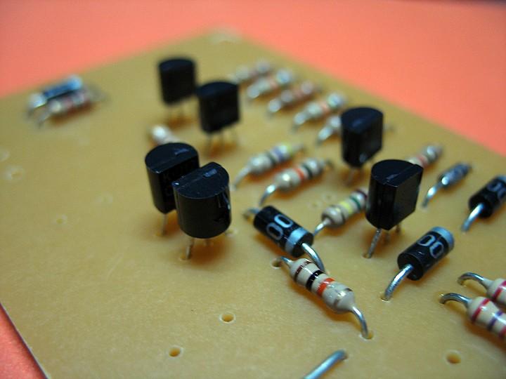
8 Insert and solder the 4 1N4004 diodes while noting their proper lead orientation. Next, insert and solder the 6 NPN transistors, pay particular attention to their proper lead orientation and make sure each is inserted properly with the correct pins in the correct holes.
9


10 Next, insert the power indicator LED2, and the rest of the capacitors. Again, ensure that all components are inserted properly while noting their proper lead orientation. Note that LED1 can be installed with a length of wire if it's to be installed in the front of the chassis. Finally, install the relays and the Faston connectors to finish the build. You may install a euroblock connector if you wish for the power supply connection.

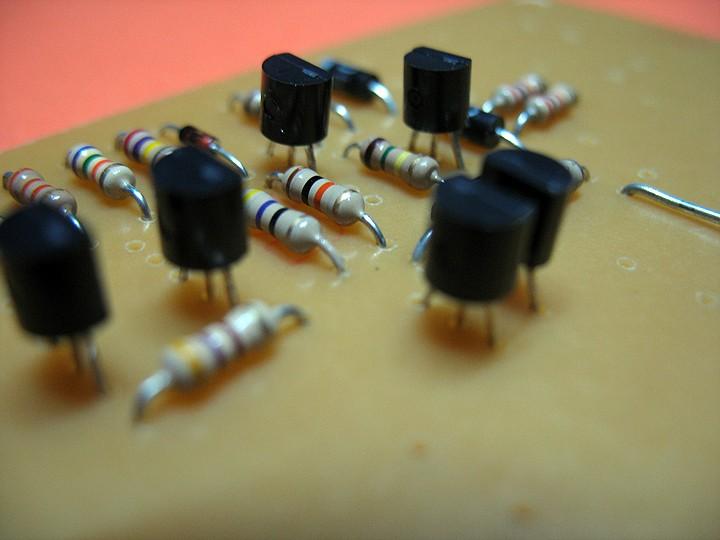
11 Shown here is a version with 6V coil relays for use with a 9 to 12VAC transformer secondary tap or a separate 250mA transformer. Checking Your Work: Building electronics stuff is fun up to the point when you are about to power it on for the first time. To help in reducing the risk of failures and boost a builder s confidence, this is my usual procedure for checking a finished board. Resistors Visually check each resistor, cross reference it with the BOM and make sure that you placed the right value in the right spot. It's also good practice to do a quick resistance test of a resistor using a DMM before soldering it in place. It's very easy to mistake a 5-band 68K resistor with a 68R resistor! Capacitors electrolytic capacitors are polarized so check and pay careful attention to their pin orientation. Make sure the marking on the capacitor matches the polarity marked on the board.

12 Diodes it is so easy to overlook the lead orientation of diodes, especially the small signal types and zener types. Check and make sure that their polarity matches the assigned polarity markings on the board. Transistors these devices have markings on their bodies that may require the use of a magnifying glass. Read and make sure that every transistor is properly oriented on the board and that the particular transistor installed is indeed the type of transistor that is required to be installed in that position. Catastrophic failure may occur if you misplace a transistor or install it the wrong way, so take your time to check and recheck. Wiring it helps if the wires you use are of different colors. For example, all V+ wires are Red, Ground wires are Black, and V- wires are Orange. That way, there won t be any confusion when doing tests and assembly of your amp. Also, make use of suitable thickness wires, but don't overdo it. Remember that it s harder to dress a thick wire. Use AWG #16 stranded hookup wires at least. Of course no one's stopping you from using those ultra high end cables for wiring the amp. Use shielded wire for all small signal carrying wires. Testing and Calibration: Things you ll need: 1. Digital Multi-Meter (DMM). Two of these would come in handy. 2. Suitable Power Transformer. 3. Piece of wire with alligator clips at both ends.

13 Shown below is the recommended wiring diagram for the diyaudio Speaker Delay and DC Protector PCB. Testing Procedures: 1. Setup a suitable power transformer. You can use a 9VAC to 12VAC if you use 6V relay coils or 18VAC to 24VAC is you use 12V relay coils. 2. Connect the probes of your DMM to AMP_IN_1 and SPKR_1. Set to check for resistance. If you have another DMM, connect the other DMM's probes to AMP_IN_2 and SPKR_2, again, set to check for resistance. As it is, you should read infinite resistance or no connection between terminals AMP_IN_1 and SPKR_1, and AMP_IN_2 and SPKR_2. 3. Connect your power transformer to terminal X1 of the board and plug it in. Immediately, you will notice LED2 light up steadily and LED1 start flashing. 4. After about 4 to 8 seconds, LED1 should stop flashing and light steadily. At the same time, both DMMs should read zero resistance. Meaning AMP_IN_1 is connected to SPKR_1 and AMP_IN_2 is connected to SPKR_2.
 7.")
14 5. To conduct a quick test for DC Protection, remove both DMMs but keep the board powered up. 6. Get your piece of wire with alligator clips on both ends and clip one end to the Cathode of Diode D6, it's the lead nearest to the band on the body of the diode. (See drawing) 7. Now connect the other end of the wire to either AMP_IN_1 or AMP_IN_2 and immediately you will notice (or hear) the relays will disengage and LED1 will start to flash again. Remove the alligator clip and after a few seconds, you will hear the relays re-engage and LED1 will stop flashing and lit up steadily. Your Speaker Delay and DC Protector is now tested and ready for duty. Special Note: Please make sure that the output of your Power Amplifier is connected to the board's AMP_IN_1 and AMP_IN_2 connectors because the DC Protection circuit monitors these terminals. Interchanging AMP_IN_1 and SPKR_1 terminals will not cause any faults but if any DC is present this will cause the circuit to disconnect, reconnect, disconnect, reconnect and cycle all over again even if the DC voltage is still present. Listening Tests and Reviews: Using The Speaker Delay and DC Protector board in my amplifier builds has always been a welcome addition. It saves my speakers from being exposed to nasty power amplifier turn-on or turn-off noises. I especially hate the thump I hear during power-on which is a normal thing for most power amplifiers whose VAS section stabilizes later than the rest of the amplifier circuitry does.
15 It's also worthwhile to note that in the years I've used these protection circuits, thankfully, they haven't affected the sound quality coming from my power amplifier. The use of quality relays is a must of course, as poor connection between the contacts will affect the sound. Feedback and Final Notes: Almost all commercial and professional power amplifiers I've seen employ the use of some sort of Speaker Delay and Protection, so why not use one in our DIY power amps? Power amplifiers that are properly designed and built using quality parts exhibit a long service life and excellent track record. Employing auxiliary protection circuits is added insurance for our speakers and makes us feel good knowing that they won't be exposed to any nasty thumps. Enjoy! JD
Pacific Antenna Easy TR Switch Kit
 Pacific Antenna Easy TR Switch Kit Kit Description The Easy TR Switch is an RF sensing circuit with a double pole double throw relay that can be used to automatically switch an antenna between a separate
Effects Loop Installation Guide
 Warnings and Disclaimer Effects Loop Installation Guide You will be working with HIGH VOLTAGE. These voltages CAN BE DEADLY if you are not extremely careful. If you are not comfortable working with HIGH
TKEY-1. CW touch key. (no electromechanical contacts) Assembly manual. Last update: June 20,
 Assembly manual. Last update: June 20,") TKEY-1 CW touch key (no electromechanical contacts) Assembly manual Last update: June 20, 2017 ea3gcy@gmail.com Updates and news at: www.ea3gcy.com Thanks for constructing the TKEY-1A CW touch key Have
TKEY-1 CW touch key (no electromechanical contacts) Assembly manual Last update: June 20, 2017 ea3gcy@gmail.com Updates and news at: www.ea3gcy.com Thanks for constructing the TKEY-1A CW touch key Have
The ability to make basic voltage and resistance measurements using a digital multimeter
 Seventh Circle Audio T15 Microphone Preamp Designed around the excellent THAT 1512 preamp IC, the T15 microphone preamp offers superb performance in any application where extremely low distortion and neutral
These are the illustrated step-by-step guidelines for upgrading your Quad 306 with the Dada Electronics upgrade-kit.
 Quad 306 DIY illustrated guidelines version 1.1 These are the illustrated step-by-step guidelines for upgrading your Quad 306 with the Dada Electronics upgrade-kit. We will replace all electrolytic capacitors,
K8099 NIXIE CLOCK. * optional enclosure TKOK19 (black) - TKOK17 (white) ** optional plexiglass enlcosure B8099 ILLUSTRATED ASSEMBLY MANUAL
 - TKOK17 (white) ** optional plexiglass enlcosure B8099 ILLUSTRATED ASSEMBLY MANUAL") Total solder points: 230 + 74 Difficulty level: beginner 1 2 3 4 5 advanced NIXIE CLOCK K8099 ** * A unique combination of both vintage and modern electronics ILLUSTRATED ASSEMBLY MANUAL H8099IP-1 * optional
Total solder points: 230 + 74 Difficulty level: beginner 1 2 3 4 5 advanced NIXIE CLOCK K8099 ** * A unique combination of both vintage and modern electronics ILLUSTRATED ASSEMBLY MANUAL H8099IP-1 * optional
Assembly Instructions for the KA Electronics Elliptic Equalizer
 Assembly Instructions for the KA Electronics Elliptic Equalizer Install IC sockets Elliptic Equalizer PC Board Stuffing Guide Place the PC Board on the work bench silkscreen side face up. Place twelve
K8086 TELEPHONE RING DETECTOR WITH RELAY OUTPUT. Simply connect in parallel with phone line. ILLUSTRATED ASSEMBLY MANUAL
 Total solder points: 61 Difficulty level: beginner 1 2 3 4 5 advanced TELEPHONE RING DETECTOR WITH RELAY OUTPUT K8086 Simply connect in parallel with phone line. Accepts standard adaptor & telephone plug.
Universal Keying Adapter 3+
 Universal Keying Adapter 3+ The Universal Keying Adapter Version 3+ kit will allow you to key nearly any transmitter or transceiver with a straight key, electronic keyer, computer serial or parallel port
Assembly Instructions (8/14/2014) Your kit should contain the following items. If you find a part missing, please contact NeoLoch for a replacement.
 Your kit should contain the following items. If you find a part missing, please contact NeoLoch for a replacement.") NeoLoch NLT-28P-LCD-5S Assembly Instructions (8/14/2014) Your kit should contain the following items. If you find a part missing, please contact NeoLoch for a replacement. Kit contents: 1 Printed circuit
NeoLoch NLT-28P-LCD-5S Assembly Instructions (8/14/2014) Your kit should contain the following items. If you find a part missing, please contact NeoLoch for a replacement. Kit contents: 1 Printed circuit
KDR00101 DMX Controlled Relay Kit
 KDR00101 DMX Controlled Relay Kit This is a DMX512-A relay kit using ANSI approved RJ-45 connectors for DMX networks. Power requirements are 12 Vdc @ 100 ma. The relay contact rating is 10 Amp @ 120 or
KDR00301 DMX Controlled Relay Kit
 KDR00301 DMX Controlled Relay Kit This is a DMX512-A relay kit using ANSI approved RJ-45 connectors for DMX networks. Power requirements are 12 Vdc @ 200 ma. The relay contact rating is 10 Amp @ 120 or
DMX CONTROLLED RELAY K8072
 Total solder points: 167 Difficulty level: beginner 1 2 3 4 5 advanced DMX CONTROLLED RELAY K8072 f the means o ol. y b y la a re 2 protoc Control DMX51 wn well-kno ILLUSTRATED ASSEMBLY MANUAL Total solder
Have Mercy Building instructions v1.1
 Have Mercy Building instructions v1.1 Table of contents Have Mercy v1.1 PCB layout... 3 Components... 4 Power section... 5 Build sequence... 5 Calibration... 6 Off board wiring... 6 Potentiometers... 6
Pacific Antenna Two Tone Generator
 Pacific Antenna Two Tone Generator Description Our Two Tone Generator kit provides two non-harmonic, sine wave signals for testing audio circuits Outputs of approximately 700Hz and 1900Hz and the combination
MP3 audio amplifier. Build Instructions. Issue 2.0
 MP3 audio amplifier Build Instructions Issue 2.0 Build Instructions Before you put any components in the board or pick up the soldering iron, just take a look at the Printed Circuit Board (PCB). The components
K8086 TELEPHONE RING DETECTOR WITH RELAY OUTPUT. Simply connect in parallel with phone line. ILLUSTRATED ASSEMBLY MANUAL H8086IP-1
 Total solder points: 61 Difficulty level: beginner 1 2 3 4 5 advanced TELEPHONE RING DETECTOR WITH RELAY OUTPUT K8086 Simply connect in parallel with phone line. Accepts standard adaptor & telephone plug.
solutions for teaching and learning
 RKAmp1 Component List and Instructions PCB layout Constructed PCB Schematic RKAmp1 Stereo Amplifier Page 1 Description The RKAmp1 stereo amplifier PCB has been designed around the 2 x 1watt stereo amplifier
Installation instructions DC Protection and Delay unit, Version 1.2 The package should contain: A piece of normal gauge yellow wire for the AC connect
 Installation instructions DC Protection and Delay unit, Version 1.2 How does the unit work? Delay: Basically a capacitor is charged via a resistor, when the voltage of the capacitor reach a certain level,
Button Code Kit. Assembly Instructions and User Guide. Single Button Code Entry System
 Button Code Kit Single Button Code Entry System Assembly Instructions and User Guide Rev 1.0 December 2009 www.alan-parekh.com Copyright 2009 Alan Electronic Projects Inc. 1. Introduction... 4 1.1 Concept
4.1 Parts and Components... IV Assembly Tips... IV Assembly Precautions... IV Required Tools, Equipment and Materials..
 IV PERSONALITY MODULE ASSEMBLY 4.1 Parts and Components............ IV-1 4.2 Assembly Tips............... IV-1 4.3 Assembly Precautions............ IV-1 4.4 Required Tools, Equipment and Materials.. IV-1
Morse Code Practice Oscillator
 Features Description Keyer speed range: Limited only by keying source True Sine wave tone output Tone Volume Control Tone Frequency Control Internal Speaker 1/8 External Speaker/Headphone Jack RCA Key
solutions for teaching and learning
 RKAmp3 Component List and Instructions PCB layout Constructed PCB Schematic RKAmp3 Stereo Amplifier Page 1 Description The RKAmp3 stereo amplifier PCB has been designed around the 2 x 7watt stereo amplifier
Uzebox Kit Assembly Guide
 Uzebox Kit Assembly Guide V1.3 Page 1 of 18 Revision History Version Date Author Description 1.0 01-Nov-2012 A.Bourque Initial release 1.1 6-Nov-2012 A.Bourque Minor corrections 1.2 28-Jan-2014 A.Bourque
K1EL Morse Code Practice Oscillator CPO
 Features This is an oscillator not a Morse keyer Input source can be a keyer or straight key Near Sine wave tone output CPO Tone Volume Control CPO Tone Frequency Control Use headphones or external speaker
LED Sequencer 1.0 / 1.5
 LED Sequencer 1.0 / 1.5 Instruction Manual Eastern Voltage Research, LLC May 2012, Rev 2 1 http://www.easternvoltageresearch.com Introduction to the LED Sequencer 1.0 Thank you for purchasing the LED Sequencer
VG-305A AC Traffic Light Controller Kit
 Galak Electronics Electronic kits and components Website: GalakElectronics.com Email: sales@galakelectronics.com Phone: (302) 832-1978 VG-305A AC Traffic Light Controller Kit Thank you for your purchase
STAGE INTERCOM KIT 1.1 SPECIFICATION. General: The lower section is a small power amplifier designed to drive headphones or a small 8ohm speaker.
 STAGE INTERCOM KIT Version 2.1.1 - March 2018 - EduTek Ltd 1.0 DESCRIPTION This intercom module comprises of two separate circuits sharing the same supply. The upper section is a pre-amplifier designed
Patch Bay. Model 9746 Assembly and Using Manual PAiA Corporation
 Patch Bay Model 9746 Assembly and Using Manual This second-generation 9700-series processing element for modular sound synthesizers is designed to provide great sound and excellent value. A two-section
CHAPTER 5. Voltage Regulator
 CHAPTER 5 Voltage Regulator In your robot, the energy is derived from batteries. Specifically, there are two sets of batteries wired up to act as voltage sources; a 9V battery, and two 1.5V batteries in
KAA Watt x 2 Class-D Audio Amplifier Kit
 KAA10021 50 Watt x 2 Class-D Audio Amplifier Kit This amplifier kit uses Texas Instruments TPA3116D2 stereo audio amplifier IC for driving speakers up to 50 watts @ 4 ohm per channel in stereo mode and
One of the great things about theme parks these days is that sometimes
 Chapter 1 Synchronising Sight and Sound with a Colour-Organ Circuit In This Chapter Preparing the project Constructing your colour organ Playing around with the circuit One of the great things about theme
KDS Channel DMX Controlled Servo Kit
 KDS00801 8-Channel DMX Controlled Servo Kit This is a DMX512-A controlled servo kit using ANSI approved RJ-45 connectors for DMX networks. Power requirements are 8-20 VDC @ 50 ma. The board features an
Advanced Strobe 1.0 Kit
 Kit Instruction Manual Eastern Voltage Research, LLC December 2013, Rev 1 1 http://www.easternvoltageresearch.com Kit Introduction to the Kit Thank you for purchasing the Kit. If you are looking for a
QUANTOM DEFRAKULATOR Build Document last updated june 2018 for PCB version 1.0
 QUANTOM DEFRAKULATOR Build Document last updated june 2018 for PCB version 1.0 The Quantom Defrakulator is a drone synthesizer with 3 square wave oscillators and one LFO (low frequency oscillator). Each
Installation/assembly manual for DCC/Power shield
 Installation/assembly manual for DCC/Power shield The DCC circuit consists of the following components: R1/R6 R2/R3 R4/R5 D1 C2 2 kω resistor ½ Watt (colour code Red/Black/Black/Brown/Brown) 10 kω resistor
AUDIO AMPLIFIER PROJECT
 Intro to Electronics 110 - Audio Amplifier Project AUDIO AMPLIFIER PROJECT In this project, you will learn how to master a device by studying all the parts and building it with a partner. Our test subject:
3 pyro output datalogger altimeter with an ATmega 328 microcontroller Kit assembly instructions
 3 pyro output datalogger altimeter with an ATmega 328 microcontroller Kit assembly instructions Version date Author Comments 1.0 29/05/2013 Boris du Reau Initial version Rocket Type Micro-max Model Mid
IR TRANSMITTER BLOK PCB ASSEMBLY INSTRUCTIONS. Copyright EduTek Ltd Rev. 2
 IR TRANSMITTER BLOK PCB ASSEMBLY INSTRUCTIONS Copyright EduTek Ltd Rev. 2 Circuit Details The circuit is shown below with a parts list of components. Check through this list and identify each component.
8 CHANNEL USB RELAY CARD
 8 CHANNEL USB RELAY CARD Use your computer USB port to connect to the outside world. Total solder points: 363 Difficulty level: beginner 1 2 3 4 5 advanced K8090 ILLUSTRATED ASSEMBLY MANUAL H8090IP-1 Features
ICTD-100CP / ICTD-101CP ICTD-102CP / ICTD-103CP
 PATENT PENDING ICTD-100CP / ICTD-101CP ICTD-102CP / ICTD-103CP Capacitor Trip Devices with Contact Protect Technology TM Operation Manual and Data sheet 2015 Intermountain Electronics, Inc. Important Notice
Uzebox Kit Assembly Guide
 Uzebox Kit Assembly Guide V1.7 Page 1 of 21 Revision History Version Date Author Description 1.0 01-Nov-2012 A.Bourque Initial release 1.1 6-Nov-2012 A.Bourque Minor corrections 1.2 28-Jan-2014 A.Bourque
QUASAR KIT No DIGITAL DOWN TIMER 99 MIN WITH PIC
 QUASAR KIT No 1173 - DIGITAL DOWN TIMER 99 MIN WITH PIC KIT 1173 is a digital countdown timer based on a micro controller, thus securing reliability and excellent operation under any circumstances. It
Total solder points: 240 Difficulty level: beginner advanced LIGHT COMPUTER K5201 ILLUSTRATED ASSEMBLY MANUAL
 Total solder points: 240 Difficulty level: beginner 1 2 3 4 5 advanced LIGHT COMPUTER K5201 16 different patterns and 7 outputs provide a unique light show. ILLUSTRATED ASSEMBLY MANUAL H5201IP-1 Features
Sega MegaDrive 1 RGB Bypass Installation Guide Rev 1.4
 Sega MegaDrive 1 RGB Bypass Installation Guide Rev 1.4 Revision 1 Board See Page 3 for important information Revision 2 Board Onboard 2k2 Pull up Resistor for CSYNC This step by step guide describes the
Advanced Lantern 1.0 Kit. Introduction to the Advanced Lantern 1.0 Kit
 Advanced LED Lantern 1.0 Instruction Manual Eastern Voltage Research, LLC Introduction to the Advanced Lantern 1.0 Kit Thank you for purchasing the Advanced Lantern 1.0 Kit. This kit is an advanced microprocessor
High Power (15W + 15W) Stereo Amplifier
 Stereo Amplifier") High Power (15W + 15W) Stereo Amplifier Build Instructions Issue 1.0 Build Instructions Before you put any components in the board or pick up the soldering iron, just take a look at the Printed Circuit
High Power (15W + 15W) Stereo Amplifier Build Instructions Issue 1.0 Build Instructions Before you put any components in the board or pick up the soldering iron, just take a look at the Printed Circuit
Snail Gear Building instructions V1.0
 Snail Gear Building instructions V1.0 Table of contents Components... 3 PCB layout... 4 General guideline for components... 5 General building tips... 5 Modifications... 6 Biasing... 7 Off board wiring...
Mini Fuzz Face. Vintage fuzz in a neat little package
 Mini Fuzz Face Vintage fuzz in a neat little package Contents of this document are 2016 Pedal Parts Ltd. No reproduction permitted without the express written permission of Pedal Parts Ltd. All rights
dual bipolar voltage controlled step sequencer DIY ASSEMBLY MANUAL v1.03
 dual bipolar voltage controlled step sequencer DIY ASSEMBLY MANUAL v1.03 Contents Contents... 2 Introduction... 3 Part Sourcing Notes for Non Kit Builders... 3 Eurorack Kit Assembly... 4 Resistors and
T100MD PLC Installation Guide
 T100MD-2424+ PLC Installation Guide LCD Display Module MCR 12 to 24V DC Power Supply for PLC Master Control Relay for Output. + - EEPROM Write-Protection when J2 at WP 14-pin LCD Display Port Two-wire
QUASAR ELECTRONICS KIT No Hi-Fi PREAMPLIFIER WITH REMOTE CONTROL
 QUASAR ELECTRONICS KIT No. 1070 Hi-Fi PREAMPLIFIER WITH REMOTE CONTROL General Description This is a hi-fi STEREO preamplifier based on a single integrated circuit which employs a revolutionary new method
Fuzz Face. Vintage fuzz with optional voltage inverter
 Fuzz Face Vintage fuzz with optional voltage inverter Contents of this document are 2014 Pedal Parts Ltd. No reproduction permitted without the express written permission of Pedal Parts Ltd. All rights
Building Morpheus v1.00a
 Building Morpheus v1.00a Version 0.95 Copyright 2009 by William Henning Updated documentation will always be available at Morpheus v0.1 in mid-2008 1 Table of Contents Introduction...4 Top of board:...4
Tone Bender Mk III. Grandaddy of super-cool vintage fuzz tone
 Tone Bender Mk III Grandaddy of super-cool vintage fuzz tone Contents of this document are 2014 Pedal Parts Ltd. No reproduction permitted without the express written permission of Pedal Parts Ltd. All
Assembly Instructions for the KA Electronics RIAA EQ Monitor Switcher
 Assembly Instructions for the KA Electronics RIAA EQ Monitor Switcher Install IC sockets EQ Monitor Switcher PC Board Stuffing Guide Place the PC Board on the bench silkscreen side face up. Drop eleven
Digital Candle 1.0 Kit
 Kit Instruction Manual Eastern Voltage Research, LLC June 2012, Rev 1 1 http://www.easternvoltageresearch.com Introduction to the Kit Thank you for purchasing the Kit. This kit is definitely a favorite
Assembly Instructions for the KA Electronics IGFO Input Gain Filter Output Board
 Assembly Instructions for the KA Electronics IGFO Input Gain Filter Output Board IGFO PC Board Stuffing Guide Install IC sockets Place the PC Board on the work bench silkscreen side face up. Place ten
Step 1 The tools & the Components The tools you need: A good quality soldering iron with a fine point (max 30) Watt or a soldering-station. A desolder
 Watt or a soldering-station. A desolder") Upgrade/revision manual Quad 44 pre amplifier. V2.5 These are the illustrated step-by-step guidelines for upgrading your Quad 44 with the Dada Electronics upgrade-kits. The Quad 44 preamp was the first
Upgrade/revision manual Quad 44 pre amplifier. V2.5 These are the illustrated step-by-step guidelines for upgrading your Quad 44 with the Dada Electronics upgrade-kits. The Quad 44 preamp was the first
EXTENDED RECORD PLAYBACK KIT. Allows you to record and play messages of up to 8 minutes long.
 K8094P 1 ILLUSTRATED LUS TED ASSEMBLY MANUAL AL H8094IP 1 EXTENDED RECORD PLAYBACK KIT Allows you to record and play messages of up to 8 minutes long. The K8094 allows you to record and play messages of
RECORD & PLAYBACK KIT
 ESSENTIAL INFORMATION BUILD INSTRUCTIONS CHECKING YOUR PCB & FAULT-FINDING MECHANICAL DETAILS HOW THE KIT WORKS ADD AN AUDIO MESSAGE TO YOUR PRODUCT WITH THIS RECORD & PLAYBACK KIT Version 2.1 Build Instructions
ArdPicProg. Arduino PIC Programmer Construction Manual. Version 1.2 Release date 03/2015. Gregor Schlechtriem
 ArdPicProg Arduino PIC Programmer Construction Manual Version 1.2 Release date 03/2015 Gregor Schlechtriem webmaster@pikoder.de www.pikoder.de Table of Contents Helpful Hints 3 Contents of the Kit and
RSL PSM-2 Power Supply Module Project: Modifying a FlatCap2
 RSL PSM-2 Power Supply Module Project: Modifying a FlatCap2 Dear Do-It-Yourselfer, The stock FlatCap2 is less than a stellar performer. Used with a CD5 CD player, for example, it gives flabby bass control,
Make Kits and Casemods
 Make Kits and Casemods This weekend, you ll learn how to make a Minty Boost usb charger and a Daisy mp3 player. After you put these together you can put them into customized cases. I made my charger fit
Single cable kit for the FCB1010
 Single cable kit for the FCB1010 1. What is it? With this kit, you can turn your FCB1010 into a phantom powered floorboard, which can do 2-way MIDI communication over one single cable. After installing
Noise Source Model 9751 Assembly and Using Manual
 Noise Source Model 9751 Assembly and Using Manual This second-generation 9700-series processing element for modular sound synthesizers is designed to provide great sound and excellent value. This module
HUB-ee BMD-S Arduino Proto Shield V1.1
 HUB-ee BMD-S Arduino Proto Shield V1.1 User guide and assembly instructions Document Version 0.5 Introduction & Board Guide 2 Schematic 3 Quick User Guide 4 Assembly Guide 6 Kit Contents 7 1) Diodes and
ARRL ETP Solder Hour Clock Kit Construction Manual
 ARRL ETP Solder 101 24-Hour Clock Kit Construction Manual Do a complete parts check cross checking the individual parts against the parts list. Pay particular attention to the color code for the resistors:
USB Controlled DMX interface
 USB Controlled DMX interface Control DMX fixtures using a PC and USB interface. Stand-alone test function that outputs all 512 channels at a time, with adjustable levels. Total solder points: 117 Difficulty
Freeze the Dizz Jameco Part No
 Freeze the Dizz Jameco Part No. 2161431 This project is based on a children s arcade game. Twenty LEDs are placed on a ring and each takes turn to light up forming a rotating light spot. If a push-button
Transcendent Frequency Counter
 Transcendent Frequency Counter with blue 2 x 16 LCD display This manual will guide you how to assemble, test and operate this frequency counter KIT. Features: The transcendent counter has two input channels
BS2p40tm OEM Module. Surface mount/through hole kit By Robert L. Doerr. Manual Revision.5
 BS2p40tm OEM Module Surface mount/through hole kit 2006 By Robert L. Doerr Manual Revision.5 NOTE: The BASIC Stamp and the BS2p40 and Interpreter chip are trademarks of Parallax. This partial kit allows
Shack Clock kit PCB Revision: QCU Rev 1 or QCU Rev 3
 1. Introduction Shack Clock kit PCB Revision: QCU Rev 1 or QCU Rev 3 Thank you for purchasing this QRP Labs Shack Clock kit. The kit uses the same PCB and bag of components as some other QRP Labs kits.
BuffaloLabs WiFi Lantern Assembly guide version 1
 BuffaloLabs WiFi Lantern Assembly guide version 1 Needed equipment: Solder iron Solder wire Cutter Wire stripper (optional) Hot glue gun Overview of the components (not including USB cable and box panels)
DELUXE STEREO AMPLIFIER KIT
 ESSENTIAL INFORMATION BUILD INSTRUCTIONS CHECKING YOUR PCB & FAULT-FINDING MECHANICAL DETAILS HOW THE KIT WORKS CREATE YOUR OWN SPEAKER DOCK WITH THIS DELUXE STEREO AMPLIFIER KIT Version 2.0 Build Instructions
[Note: Power adapter is not included in the kits. Users need to prepare a 9 12 V ( >300mA capacity ) DC power supply]
![[Note: Power adapter is not included in the kits. Users need to prepare a 9 12 V ( >300mA capacity ) DC power supply]](/thumbs/76/74094055.jpg "[Note: Power adapter is not included in the kits. Users need to prepare a 9 12 V ( >300mA capacity ) DC power supply]") 062 LCD Oscilloscope Assembly Notes Applicable Models: 06203KP, 06204KP DN062-18v02 Important Notes 1. Some components shown in the schematic and PCB layout are for options or adjustments. They do not
062 LCD Oscilloscope Assembly Notes Applicable Models: 06203KP, 06204KP DN062-18v02 Important Notes 1. Some components shown in the schematic and PCB layout are for options or adjustments. They do not
Parts List: Part # Tools List: Instructions:
 Parts List: Part # 1 pair of Dayton Audio B652s 300-652 1 Dayton Audio DTA-2 amplifier 300-385 1 MP3 module 320-350 1 7805 +5 VDC voltage regulator 7805 1 12 VDC 2A power supply 129-077 1 2.1 mm panel
A Backlighted LCD for your K1
 A Backlighted LCD for your K1 (K1BKLTKIT) Tom Hammond - NØSS, July 27, 2006 Rev C Thanks to Wayne Burdick, N6KR for suggesting this implementation of backlighting the K1 display. APPLICABILITY This modification
TuBbika SMR-4-PLUS voicecard
 TuBbika SMR-4-PLUS voicecard Assembly instructions We assume you know soldering. If you don t, look first at this tutorial. Be patient! And if you have any doubt, head to the forum never be afraid to ask!
HARDWARE OPERATIONS MANUAL
 HARDWARE OPERATIONS MANUAL Table of Contents INTRODUCTION... 2 SECTION 1: HARDWARE COMPONENT ASSEMBLIES... 2 MECHANICAL HARDWARE AND CASE... 2 PCB ASSEMBLY... 4 ISD RECORDING CIRCUIT... 5 BREADBOARD ASSEMBLY...
K2579 UNIVERSAL START/STOP TIMER. Specifications
 Total solder points: 49 Difficulty level: beginner 1 2 3 4 5 advanced UNIVERSAL START/STOP TIMER K2579 Small size timer provides up to 60 minutes delay. Specifications Relay output with switchover contact.
Little Screamerv2.0. Stripped-back, bufferless Tube Screamer
 Little Screamerv2.0 Stripped-back, bufferless Tube Screamer Contents of this document are 2016 Pedal Parts Ltd. No reproduction permitted without the express written permission of Pedal Parts Ltd. All
ONE CHANNEL DUAL OUTPUT RECEIVER
 Total solder points: 89 Difficulty level: beginner 1 2 3 4 5 advanced ONE CHANNEL DUAL OUTPUT RECEIVER For use with K8058 / VM118R transmitters. K8070 A single transmitter key-press activates two independent
Plasma Panel Replacement Guide DU-42PX12X
 Plasma Panel Replacement Guide DU-42PX12X Panel Replacement: At this point, the panel has been determined to be defective and replacement is necessary. Upon receiving the replacement panel, it must be
Two-wire. Jumper for 12V. J2 Enable Adjust D/A1. Super PLC Warning: Warranty Void if this label is damaged 62256LP-12 CMOS RAM 4.
 T100MD-888+ PLC Installation Guide LCD Display Module 1N4007 (optional) + - 12 to 24V DC Power Supply for PLC Contrast Adjust 14-pin LCD Display port Two-wire RS485 + - Jumper for 12V 1000µ F 5 E.Cap (Optional)
Bill of Materials: Picaxe-based IR Control Module Pair PART NO
 Picaxe-based IR Control Module Pair PART NO. 2171014 The IRGEII is an IR (Infra Red) Transmitter and Receiver pair that uses a 38 KHZ frequency of invisible light to communicate simple instructions. The
Electronics Construction Manual
 Electronics Construction Manual MitchElectronics 2018 Version 1 07/05/2018 www.mitchelectronics.co.uk CONTENTS Introduction 3 How To Solder 4 Resistors 5 Capacitors 6 Diodes and LEDs 7 Switches 8 Transistors
Bill of Materials: Turn Off the Lights Reminder PART NO
 Turn Off the Lights Reminder PART NO. 2209650 Have you ever woke up early in the morning to find out that the kids (or adults) in your home forgot to turn off the lights? I've had that happen a number
The PUMPKIN LIGHT LED
 The PUMPKIN LIGHT LED PUMPKIN LIGHT LED By Mark McCuller Email: mcculler@mail.com DESIGN SUMMARY The PUMPKIN LIGHT LED By: Mark McCuller The Pumpkin Light LED is a battery-powered device that illuminates
ADDENDUM FOR 20, 27, & 28 OPTIONS
 ADDENDUM FOR 20, OPTIONS GENERAL The 20, 27, and 28 option provides for an alarm contact OR an AC transfer switch on EXELTECH XP Series inverters. The alarm relay monitors the inverter s AC output and
EL Wire sequencer / power supply PART NO
 EL Wire sequencer / power supply PART NO. 2206213 The EL Wire sequencer is a EL wire power supply capable of powering 50 plus feet of 2.6mm El Wire and 8 ports controlled by a BS2sx. A menu driven command
T100MD (Rev D-1) PLC Installation Guide
 PLC Installation Guide") T100MD-1616+ (Rev D-1) PLC Installation Guide LCD Display Module 1N4007 (optional) + - 12 to 24V DC Power Supply for PLC EEPROM Write-Protection when J2 at WP 14-pin LCD Display Port Two-wire RS485 + -
T100MD-1616+ (Rev D-1) PLC Installation Guide LCD Display Module 1N4007 (optional) + - 12 to 24V DC Power Supply for PLC EEPROM Write-Protection when J2 at WP 14-pin LCD Display Port Two-wire RS485 + -
Code Practice Oscillator (CPO)
") Code Practice Oscillator (CPO) Overview Many thanks for your purchase of this code practice oscillator or CPO, this guide is intended to allow you to quickly get operational. The CPO comprises an approx.
Code Practice Oscillator (CPO) Overview Many thanks for your purchase of this code practice oscillator or CPO, this guide is intended to allow you to quickly get operational. The CPO comprises an approx.
EE 354 August 1, 2017 Assembly of the AT89C51CC03 board
 EE 354 August 1, 2017 Assembly of the AT89C51CC03 board The AT89C51CC03 board comes as a kit which you must put together. The kit has the following parts: No. ID Description 1 1.5" x 3.25" printed circuit
LDD M SERIES INSTRUCTION MANUAL LDD M SERIES
 TM LDD M SERIES LDD M SERIES INSTRUCTION MANUAL P O Box Bozeman, MT 9 Phone (0) -90 Fax (0) -9 email sales@wavelengthelectronics.com www.wavelengthelectronics.com TABLE OF CONTENTS Features... Customer
Chill Interface PCB Assembly Instructions
 ExcelValley Chill Interface PCB Waveblaster Module MIDI Interface Board Chill Limited Edition V2 Assembly Kit Standalone midi interface board for Waveblaster synthesizer modules. Suitable for most Waveblaster
XYLOPHONE KIT ESSENTIAL INFORMATION. Version 2.0 CREATE YOUR OWN ELECTRONIC MUSICAL INTRUMENT WITH THIS
 ESSENTIAL INFORMATION BUILD INSTRUCTIONS CHECKING YOUR PCB & FAULT-FINDING MECHANICAL DETAILS HOW THE KIT WORKS CREATE YOUR OWN ELECTRONIC MUSICAL INTRUMENT WITH THIS XYLOPHONE KIT Version 2.0 Build Instructions
Digital Flame 1.0 Kit
 Digital Flame 1.0 Kit Instruction Manual Eastern Voltage Research, LLC June 2012, Rev 1 1 http://www.easternvoltageresearch.com Introduction to the Digital Flame 1.0 Kit Thank you for purchasing the Digital
orban FIELD ENGINEERING BULLETIN Purpose: Units Affected: Replacement Kit, Orban Part # Replacing SSM2017 Op-Amps
 orban FIELD ENGINEERING BULLETIN March 27, 2002 Orban Models: 2200, 6200, 6200S, 8200, 8282, 9200 Purpose: Due to the elimination of the SSM2017 by its manufacturer, Orban has had to choose a replacement
Butterfly Laser Diode Mount
 LM14S2 Butterfly Laser Diode Mount Operating Manual LM14S2 Laser On TEC Driver LD Driver THORLABS, Inc. Ph: (973) 579-7227 435 Route 206N Fax: (973) 383-8406 Newton, NJ 07860 USA www.thorlabs.com 10614-D02