Eddie Control Board with Power Connector (#28993) Eddie Control Board PCB (# )
|
|
|
- Marshall Poole
- 6 years ago
- Views:
Transcription
1 Web Site: Forums: forums.parallax.com Sales: Technical: Office: (916) Fax: (916) Sales: (888) Tech Support: (888) Eddie Control Board with Power Connector (#28993) Eddie Control Board PCB (# ) The Eddie Control Board provides a complete single-board solution to control the Eddie Robot Platform (28992). Designed to be flexible and expandable, the Eddie Control Board is also well suited for other mobile robot platforms. While the board has a wide input voltage range, it is primarily targeted to 12 VDC battery-powered applications. The heart of the Eddie Control Board is the Propeller P8X32A microcontroller. The Propeller chip s eight 32-bit cores provide incredible power and flexibility. The board includes high-current motor drivers, an eight-channel 10-bit ADC, and access to lots of digital I/O. Multiple regulated power supplies (12 V, 5 V, and 3.3 V) and three switchable auxiliary power ports support optional accessories for your robot. This document provides details and specifications about the Eddie Control Board hardware only. For additional information and for details about the latest firmware, go to Features Powered by the Propeller P8X32A with eight 32-bit cores Integrated high-current motor drivers Eight-channel 10-bit ADC Up to 16 general purpose digital I/O On-board regulated power supplies for 12 V, 5 V, and 3.3 V. Three auxiliary power ports provide switchable battery voltage for accessories 5 A auxiliary power fuse, and 20 A motor power fuse Four diameter mounting holes for #4 screws, spaced at 4.60 x 3.35 in (11.68 x 8.51 cm) Key Specifications Power requirements: Main board operating voltage (VCC MAIN ) 6.75 to 18 V; Motor driver operating voltage (VCC MOTORS ) 5.5 to 16 V Communication Interface: USB mini-b connector (enumerates as a serial COM port) Operating temperature: 32 to 158 F (0 to 70 C) Dimensions: 5.05 x 3.80 x 0.97 in (12.83 x 9.65 x 2.46 cm) Application Ideas Autonomous navigation robots Telepresence robots Two-wheeled balancing robots Robotic arm Manufacturing automation equipment Note: #28993 includes the Eddie Control Board (# ) and the Eddie Control Board Power Connector (# ). When the Eddie Control Board is purchased as part of the Eddie Robot Platform kit (#28992) the Power Connector is not required; that kit includes the Eddie Wiring Harness. Copyright Parallax Inc. Eddie Control Board (# , 28993) v1.2 2/10/2012 Page 1 of 9


")


 Reset")

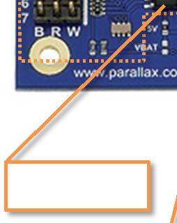
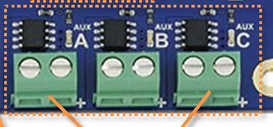
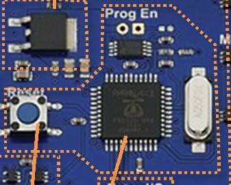
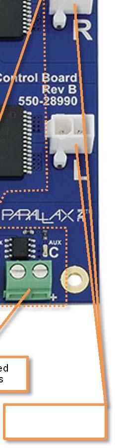
2 Board Overview Digital I/O 5 VDC Regulator 3.3 VDC Regulator Aux. Power Fuse (5 A) Regulated Power Headers Power Out for Kinect Camera 12 VDC Regulator (Kinect Power) Power Input Port Motor Power Fuse (20 A) Integrated H-bridges 10-bit, 8-channel ADC USB Port Power Enable Switch AUX Switched Power Ports Fan Port (5 V) Reset Button Propeller P8X32A Microcontroller Extra I/O Left and Right Motor Plugs Copyright Parallax Inc. Eddie Control Board (# , 28993) v1.2 2/10/2012 Page 2 of 9

3 WARNING! After switching main board power off, wait at least 5 seconds before switching power back on. Rapid and repetitive power cycling of the board and motor power supplies causes significant stress on electronic components and may damage the board and/or connected electronic accessories. After prolonged operation, use care when handling the board as some components may be hot to touch. This board contains components which are sensitive to static electric discharge. Ensure proper grounding prior to operating on or around the board. Absolute Maximum Ratings Absolute Maximum Ratings are limits beyond which device damage may occur. Refer to Electrical Characteristics section (page 4) for operating specifications. Symbol Parameter Value Units Main Board VCC MAIN Supply voltage for main board 24 V H-bridges T A Operating temperature 0 to 70 C T ST Storage Temperature -55 to 150 C VCC MOTORS Supply voltage for motor H-bridges 25 V I MOTORS(MAX) Maximum H-bridge output current (surge) (1) 20 A AUX Switched Power Ports ADC Digital I/O Fan Port I D(AUX) Open-drain MOSFET switch current (2) 5 A V IH(ADC) ADC input high voltage V OUT(5V) V V IL(ADC) ADC input low voltage V OUT(5V) 0.6 V I I/O(MAX) I/O pin current (on any I/O pin) 40 ma I D(FAN) Open-drain MOSFET switch current 320 ma Notes: 1. Each H-bridge has over-current and over-temperature protection; however, repeated stress will reduce life. Therefore the maximum current is limited by the protective 20 A fuse. Maximum current is the combined total for both channels. 2. Maximum current for AUX switched power ports is limited by protective 5 A fuse. Maximum current is the combined total for all channels. Copyright Parallax Inc. Eddie Control Board (# , 28993) v1.2 2/10/2012 Page 3 of 9
4 Electrical Characteristics Unless otherwise noted, all parameters apply at VCC Main = 12V, VCC Motors = 12V, T A = 0C to +70C. Unless otherwise noted, typical values apply for VCC Main = 12V, VCC Motors = 12V, T A = +25C. Symbol Parameter Conditions Min Typ Max Units Power Input Port VCC MAIN Supply voltage for main board V I MAIN(SUPPLY) 12 VDC Regulator Supply current OFF state VCC MAIN = 12V T A = 25C Board state VCC MAIN = 12V T A = 25C 345 A 20.6 ma V OUT(12V) Regulated output voltage V I OUT(12V) Maximum total output current 2.2 A V RIPPLE(12V) Typical V OUT ripple under load I OUT = 1.2A 200 mv P-P 5 VDC Regulator V OUT(5V) Regulated output voltage V I OUT(5V) Maximum total output current 3.0 A V RIPPLE(12V) Typical V OUT ripple under load I OUT = 500mA 15 mv P-P 3.3 VDC Regulator V OUT(3.3V) Regulated output voltage V I OUT(3.3V) Maximum total output current (1) T A 25C 1000 ma T A = 70C 625 ma H-bridges (2) VCC MOTORS Supply voltage for motor H-bridges V I MOTORS(SUPPLY) I OUT(MOTOR) Supply Current Motor driver continuous output current OFF state VCC MOTORS = 12V T A = 25C Motors state VCC MOTORS = 12V T A = 25C 22 A 4.5 ma R ONHS Static high-side resistance 28 R ONLS Static low-side resistance 10 ±10 A f PWM PWM frequency 0 20 khz t OFF(MIN) PWM minimum off time (3) 6 s m Copyright Parallax Inc. Eddie Control Board (# , 28993) v1.2 2/10/2012 Page 4 of 9
5 Symbol Parameter Conditions Min Typ Max Units AUX Switched Power Ports (4) V DSS(AUX) Drain-source breakdown voltage 30 V I D(AUX) Continuous drain current (5) 5 A R DS-ON(AUX) Static drain-source on-resistance 22 m ADC (6) V RANGE Input voltage range for ADC1-7 pins 0 V OUT(5V) V LSB Least significant bit (resolution) 4.88 mv/bit f CLK ADC clock frequency 3.6 MHz t CONV ADC sample conversion time 10 clk cyc. t SAMPLE ADC input sample time 1.5 clk cyc. f SAMPLE ADC throughput rate 200 Ksps Digital I/O (7) Fan Port R S Protective series resistance 4.7 k I D(FAN) Continuous drain current 250 ma Notes: 1. The 3.3 V linear regulator can supply up to 1 A at 25 C. Above 25 C, maximum current is de-rated according to ambient temperature (T A ) based on the following equation: I OUT(3.3V) = (150 C T A )/(75 C/W * 1.7 V). 2. For further details and specifications for the H-bridge drivers, please refer to the component datasheet for the STMicroelectronics VNH2SP30-E. 3. To avoid false Short to Battery detection during PWM operation, the PWM signal must be low for a time longer than 6 s. 4. For further details and specifications for the low-side AUX power MOSFET switches, please refer to the component datasheet for the Diodes Inc. DMG4496SSS. 5. Maximum MOSFET open-drain output current is limited by protective 5 A fuse. 6. For further details and specifications for the ADC, please refer to the component datasheet for the Microchip MCP For further details and specifications for the Propeller microcontroller and its I/O pin capabilities please see the P8X32A component datasheet. Operating Description Power Input Port Main board power and motor power are supplied to the board through a high-current 3-pin header. The header is part of the Molex Mini-Fit Sr. series of connectors. The pin functions are shown below. Pin GND Main Motors Function Common ground for main board power and motor power Input supply for main board circuitry, power supplies, and AUX switched power ports. Power supply for H-bridge drivers only. Power to this pin is routed through the 20 A fuse. The isolation of the Motor power supply from the rest of the board and Main circuitry allows the motors to be fully disabled without affecting operation or power to any other part of the board. Copyright Parallax Inc. Eddie Control Board (# , 28993) v1.2 2/10/2012 Page 5 of 9
6 12 VDC Regulator The integrated 12 VDC buck-boost switching regulator provides a consistent stable output voltage across the entire operating input voltage range. For high values of VCC MAIN the regulator operates entirely in buck mode, but as input voltage decreases the regulator gradually transitions into a buck-boost mode to seamlessly maintain the output voltage at 12 V. The 12 VDC regulator circuit is designed to supply power to a Microsoft Kinect camera through the boardmounted Molex Micro-Fit 3.0 header. Supplied with each Eddie Robot Platform (28990 and 28992), the modified Kinect adapter cable uses the corresponding mating connector to allow easy assembly. The Kinect camera requires a 12 V power supply rated up to 1.08 A capacity. The on-board 12 VDC regulator circuitry was intentionally designed to supply up to 2.2 A total output current to accommodate any extra user-added circuitry requiring regulated 12 V. The regulated power header marked 12V provides convenient access to this 12 VDC regulated supply. Users may draw up to the full rated 2.2 A from this header; however when a Kinect camera is attached, no more than 1.12 A should be drawn from this header to remain below stated limits and ensure proper operation. 5 VDC Regulator The integrated 5 VDC buck switching regulator provides up to 3 A total current to several on-board circuits as well as any attached 5 V sensors and accessories. The 5 VDC regulator also supplies power to the 3.3 V linear regulator. The center column of pins on the Digital I/O headers and ADC headers are connected directly to this 5 VDC regulated supply. The regulated power header marked 5 V also provides convenient access to this power supply. 3.3 VDC Regulator The 3.3 VDC linear regulator provides clean supply voltage to the Propeller microcontroller and other associated 3.3 V circuitry. Note: under certain conditions instantaneous high-current step transients may cause ringing in the output voltage. At T A = 25C, the regulator can supply up to 1 A total output current, but at higher temperature the maximum current must be de-rated according to ambient temperature (T A ) based on the following equation: Regulated Power Headers For convenience, 2-pin female headers are installed to provide access to each regulated supply net. Power may be drawn from these headers to power additional user-circuitry as long as the total output current for each regulator does not exceed the specified ratings. Copyright Parallax Inc. Eddie Control Board (# , 28993) v1.2 2/10/2012 Page 6 of 9
7 Power Enable Switch The power enable switch controls the operating mode of the regulators and H-bridges according to the state table shown below. Position State of Operation 12 VDC and 5 VDC Regulators H-bridge Drivers STBY/OFF (1) * Disabled Disabled Board Enabled Disabled Motors Enabled Enabled Notes: 1. Rev A boards show silkscreen text as OFF, while Rev B and later boards show silkscreen text as STBY. The circuits relating to this feature were not changed. In the STBY/OFF state, the switch does not actually break the electrical connection to the entire board. All the circuits are disabled but battery power is still present and a very small amount of current is drawn (typically around 345 A). The Eddie Robot Platform comes with large capacity sealed lead-acid batteries totaling 14.4 Ah, so this small current draw is insignificant. In fact, the batteries own self-discharge rate is several times larger than the standby current of the Eddie Control Board. Additionally, sealed lead-acid batteries should be recharged at least every few months to maintain proper battery health regardless of whether the batteries were used or not. In applications where battery capacity is in question, external high-current (25 A minimum recommended) power switches should be wired in series with the Main and/or Motors terminals on the power input port connector. H-bridges The board is equipped with two high-current integrated full H-bridge drivers. While each H-bridge IC is technically rated up to a maximum of 30 A output current (according to the device datasheet), design trade-offs and thermal limitations require each driver be de-rated to 10 A continuous per channel. This is more than adequate for the motors included in the Eddie Robot Platform as well as motors typically used in most small to mid-sized robotics applications. The Motors terminal on the power input port is connected to the supply voltage of each H-bridge through a 20 A mini-blade automotive fuse. For safety and circuit reliability, this fuse should only be replaced with an equivalent 20 A fast-blow mini-blade fuse. AUX Switched Power Ports The auxiliary (AUX) switched power ports provide unregulated power from the Main terminal on the power input port through a 5 A mini-blade automotive fuse to the + side (on the right) of each screw terminal. A power MOSFET switch then selectively switches the low side of the terminal (on the left) to ground, turning on whatever accessory is connected to the port. The MOSFET gates for switches A, B, and C are connected to Propeller pins P16, P17, and P18 respectively. These AUX switched power ports are very useful for powering LED light strips, auxiliary motors, and other electronic accessories and allows for these devices to be controlled in software. Copyright Parallax Inc. Eddie Control Board (# , 28993) v1.2 2/10/2012 Page 7 of 9
8 Propeller Microcontroller The Propeller P8X32A contains eight 32-bit microcontroller cores each operating at up to 80 MHz. An onboard 512 K-bit EEPROM provides storage for program memory as well as ample storage for additional non-volatile data. Application firmware can be loaded into RAM or automatically loaded from the external EEPROM on power-up. In some applications it may be useful to lock the firmware into EEPROM so it cannot be overwritten either intentionally or unintentionally. For this purpose, through-hole pads were provided as an option to install a header or jumper wire to disable EEPROM write capability. By default, the pads are left unpopulated so reading, writing, and programming are fully enabled. When a jumper is installed to short the two pads together, then EEPROM programming/writing is disabled but reading will still be enabled. A 5 MHz crystal oscillator and reset button complete the onboard Propeller circuitry. Digital I/O and Extra I/O Most of the Propeller s 32 general purpose I/O pins are used to interface with on-board peripherals, or connect to headers for sensor interfacing. While there are already 12 general purpose digital I/O pins brought out (including the Encoders section), each of these pins has a 4.7 k series resistor for protection. This allows direct 3.3 V or 5 V sensor interfacing while preventing damage to the Propeller. However in situations where direct connection to Propeller I/O pins is necessary (or using a resistance other than 4.7 k), four Extra I/O pins have been brought out to pads through 0 resistors. If necessary, the 0 resistors can be replaced with any other desired value. The Digital I/O pins are brought out to twelve 3-pin headers near the edge of the board. The order of the pins from left to right is: Ground, 5 V, Signal. Some rules of thumb to remember this order is to keep the signal wire (typically colored white) close to the white silkscreen line located toward the center of the board (to the right of the header). Additionally, having the signal wires oriented toward the center of the board results in the shortest signal path back to the Propeller I/O pins. ADC For the analog to digital converter, the board is equipped with the Microchip MCP3008 which is an 8-channel, 10-bit ADC. For further device details about this ADC, please refer to the manufacturer s datasheet. On this board, only seven of the eight ADC channels are brought out to 3-pin headers. The eighth channel is connected through a voltage divider to VCC MAIN, the main supply voltage to the board. This allows convenient measurement and monitoring of the battery voltage level by application code. Fan Port During typical operation, the power dissipated by all the circuits will be minimal and a cooling fan is not necessary. However, when power dissipation becomes an issue due to continuously high motor output current or current draw from the regulators near the stated maximum limits, a cooling fan can be used to improve and extend circuit operation. The fan port is populated with a 0 resistor to the 5 VDC net (located near the fan port just below the ADC). Many 12 V fans still operate well at 5 V and are typically much quieter. If desired, the 0 resistor can be de-soldered and repositioned directly below its current location to instead route VCC MAIN to the fan port. Note that in this configuration, the low-side MOSFET switch will still turn off when the power enable switch is in the STBY/OFF state. Copyright Parallax Inc. Eddie Control Board (# , 28993) v1.2 2/10/2012 Page 8 of 9
9 Additional Resources and Information For additional information and resources go to Revision History Version 1.0 Version 1.1 Version 1.2 Initial product documentation release. In Power Enable Switch section (page 7), updated table and notes to mention silkscreen differences from Rev A to Rev B and later boards. Added further explanation in the Fan Port section (page 8) about voltage configurability option. Updated images for Rev B of the board. Note added to the bottom of page 1. Copyright Parallax Inc. Eddie Control Board (# , 28993) v1.2 2/10/2012 Page 9 of 9
Propeller Proto Board (#32212) Propeller Proto Board USB (#32812) Proto Board Accessory Kit (# )
 Propeller Proto Board USB (#32812) Proto Board Accessory Kit (# )") Web Site: www.parallax.com Forums: forums.parallax.com Sales: sales@parallax.com Technical: support@parallax.com Office: (916) 624-8333 Fax: (916) 624-8003 Sales: (888) 512-1024 Tech Support: (888) 997-8267
Web Site: www.parallax.com Forums: forums.parallax.com Sales: sales@parallax.com Technical: support@parallax.com Office: (916) 624-8333 Fax: (916) 624-8003 Sales: (888) 512-1024 Tech Support: (888) 997-8267
Propeller Activity Board (#32910)
") Web Site: www.parallax.com Forums: forums.parallax.com Sales: sales@parallax.com Technical: support@parallax.com Office: (916) 624-8333 Fax: (916) 624-8003 Sales: (888) 512-1024 Tech Support: (888) 997-8267
Web Site: www.parallax.com Forums: forums.parallax.com Sales: sales@parallax.com Technical: support@parallax.com Office: (916) 624-8333 Fax: (916) 624-8003 Sales: (888) 512-1024 Tech Support: (888) 997-8267
Propeller Project Board USB (#32810)
") Web Site: www.parallax.com Forums: forums.parallax.com Sales: sales@parallax.com Technical: support@parallax.com Office: (916) 624-8333 Fax: (916) 624-8003 Sales: (888) 512-1024 Tech Support: (888) 997-8267
Web Site: www.parallax.com Forums: forums.parallax.com Sales: sales@parallax.com Technical: support@parallax.com Office: (916) 624-8333 Fax: (916) 624-8003 Sales: (888) 512-1024 Tech Support: (888) 997-8267
Web Site: Forums: forums.parallax.com Sales: Technical:
 Web Site: www.parallax.com Forums: forums.parallax.com Sales: sales@parallax.com Technical: support@parallax.com Office: (916) 624-8333 Fax: (916) 624-8003 Sales: (888) 512-1024 Tech Support: (888) 997-8267
Propeller Board of Education (#32900)
") Web Site: www.parallax.com Forums: forums.parallax.com Sales: sales@parallax.com Technical: support@parallax.com Office: (916) 624-8333 Fax: (916) 624-8003 Sales: (888) 512-1024 Tech Support: (888) 997-8267
Web Site: www.parallax.com Forums: forums.parallax.com Sales: sales@parallax.com Technical: support@parallax.com Office: (916) 624-8333 Fax: (916) 624-8003 Sales: (888) 512-1024 Tech Support: (888) 997-8267
Web Site: Forums: forums.parallax.com Sales: Technical:
 Web Site: www.parallax.com Forums: forums.parallax.com Sales: sales@parallax.com Technical: support@parallax.com Office: (916) 624-8333 Fax: (916) 624-8003 Sales: (888) 512-1024 Tech Support: (888) 997-8267
PWR-I/O-DB Power and I/O Daughterboard (#28301)
") Web Site: www.parallax.com Forums: forums.parallax.com Sales: sales@parallax.com Technical: support@parallax.com Office: (916) 624-8333 Fax: (916) 624-8003 Sales: (888) 512-1024 Tech Support: (888) 997-8267
Web Site: www.parallax.com Forums: forums.parallax.com Sales: sales@parallax.com Technical: support@parallax.com Office: (916) 624-8333 Fax: (916) 624-8003 Sales: (888) 512-1024 Tech Support: (888) 997-8267
XBee USB Adapter Board (#32400)
") Web Site: www.parallax.com Forums: forums.parallax.com Sales: sales@parallax.com Technical: support@parallax.com Office: (916) 624-8333 Fax: (916) 624-8003 Sales: (888) 512-1024 Tech Support: (888) 997-8267
Web Site: www.parallax.com Forums: forums.parallax.com Sales: sales@parallax.com Technical: support@parallax.com Office: (916) 624-8333 Fax: (916) 624-8003 Sales: (888) 512-1024 Tech Support: (888) 997-8267
Web Site: Forums: forums.parallax.com Sales: Technical:
 Web Site: www.parallax.com Forums: forums.parallax.com Sales: sales@parallax.com Technical: support@parallax.com Office: (916) 624-8333 Fax: (916) 624-8003 Sales: (888) 512-1024 Tech Support: (888) 997-8267
Board Of Education USB (#28850)
") 599 Menlo Drive, Suite 100 Rocklin, California 95765, USA Office: (916) 624-8333 Fax: (916) 624-8003 Sales: sales@parallax.com 1-888-512-1024 Tech Support: support@parallax.com 1-888-99-STAMP Web Site:
599 Menlo Drive, Suite 100 Rocklin, California 95765, USA Office: (916) 624-8333 Fax: (916) 624-8003 Sales: sales@parallax.com 1-888-512-1024 Tech Support: support@parallax.com 1-888-99-STAMP Web Site:
EZ-Bv4 Datasheet v0.7
 EZ-Bv4 Datasheet v0.7 Table of Contents Introduction... 2 Electrical Characteristics... 3 Regulated and Unregulated Power Pins... 4 Low Battery Warning... 4 Hardware Features Main CPU... 5 Fuse Protection...
Web Site: Forums: forums.parallax.com Sales: Technical:
 Web Site: www.parallax.com Forums: forums.parallax.com Sales: sales@parallax.com Technical: support@parallax.com Office: (916) 624-8333 Fax: (916) 624-8003 Sales: (888) 512-1024 Tech Support: (888) 997-8267
DSP-BASED MOTOR CONTROLLER FOR THREE-PHASE BRUSHLESS DC MOTORS
 DSP-BASED MOTOR CONTROLLER FOR THREE-PHASE BRUSHLESS DC MOTORS FEATURES / BENEFITS Embedded Motor Control DSP (ADMCF328) improves higher level system integration and flexibility 7A phase current (cycle-by-cycle
Proto-DB (#28310): Prototyping Daughterboard
: Prototyping Daughterboard") Web Site: www.parallax.com Forums: forums.parallax.com Sales: sales@parallax.com Technical: support@parallax.com Office: (916) 624-8333 Fax: (916) 624-8003 Sales: (888) 512-1024 Tech Support: (888) 997-8267
Web Site: www.parallax.com Forums: forums.parallax.com Sales: sales@parallax.com Technical: support@parallax.com Office: (916) 624-8333 Fax: (916) 624-8003 Sales: (888) 512-1024 Tech Support: (888) 997-8267
Goal: We want to build an autonomous vehicle (robot)
") Goal: We want to build an autonomous vehicle (robot) This means it will have to think for itself, its going to need a brain Our robot s brain will be a tiny computer called a microcontroller Specifically
Goal: We want to build an autonomous vehicle (robot) This means it will have to think for itself, its going to need a brain Our robot s brain will be a tiny computer called a microcontroller Specifically
MP6500 Stepper Motor Driver, Digital Current Control
 This breakout board for the MPS MP6500 micro stepping bipolar stepper motor driver is Pololu s latest stepper motor driver. The module has a pinout and interface that are very similar to that of our popular
PowerPal Selectable Voltage 3-Amp Breadboard Power Supply (#32133)
") Web Store: www.parallax.com Office: (916) 624-8333 Tutorials: learn.parallax.com Educator Hotline: (916) 701-8625 Sales: sales@parallax.com Sales: (888) 512-1024 Tech Support: support@parallax.com Tech Support:
Web Store: www.parallax.com Office: (916) 624-8333 Tutorials: learn.parallax.com Educator Hotline: (916) 701-8625 Sales: sales@parallax.com Sales: (888) 512-1024 Tech Support: support@parallax.com Tech Support:
DB-Expander Daughterboard-to-SIP (#28325)
") Web Site: www.parallax.com Forums: forums.parallax.com Sales: sales@parallax.com Technical: support@parallax.com Office: (916) 624-8333 Fax: (916) 624-8003 Sales: (888) 512-1024 Tech Support: (888) 997-8267
Web Site: www.parallax.com Forums: forums.parallax.com Sales: sales@parallax.com Technical: support@parallax.com Office: (916) 624-8333 Fax: (916) 624-8003 Sales: (888) 512-1024 Tech Support: (888) 997-8267
ELEV-8 Flight Controller (#80204)
") Web Site: www.parallax.com Forums: forums.parallax.com Sales: sales@parallax.com Technical: support@parallax.com Office: (916) 624-8333 Fax: (916) 624-8003 Sales: (888) 512-1024 Tech Support: (888) 997-8267
Web Site: www.parallax.com Forums: forums.parallax.com Sales: sales@parallax.com Technical: support@parallax.com Office: (916) 624-8333 Fax: (916) 624-8003 Sales: (888) 512-1024 Tech Support: (888) 997-8267
AVR Intermediate Development Board. Product Manual. Contents. 1) Overview 2) Features 3) Using the board 4) Troubleshooting and getting help
 Overview 2) Features 3) Using the board 4) Troubleshooting and getting help") AVR Intermediate Development Board Product Manual Contents 1) Overview 2) Features 3) Using the board 4) Troubleshooting and getting help 1. Overview 2. Features The board is built on a high quality FR-4(1.6
AVR Intermediate Development Board Product Manual Contents 1) Overview 2) Features 3) Using the board 4) Troubleshooting and getting help 1. Overview 2. Features The board is built on a high quality FR-4(1.6
Shack Clock kit. U3S Rev 2 PCB 1. Introduction
 Shack Clock kit U3S Rev 2 PCB 1. Introduction Thank you for purchasing the QRP Labs Shack Clock kit. This clock uses the Ultimate3S QRSS/WSPR kit hardware, but a different firmware version. It can be used
Universal Adapter Board for NI sbrio-9606
 Universal Adapter Board for NI sbrio-9606 This document provides dimensions, pinouts, connectivity information, and specifications for the Universal Adapter Board RS-9002. The devices are referred to inclusively
Rapid40i PIC Prototyping PCB User Manual
 Description This is a PCB designed to facilitate the rapid prototyping of a device based on a 40 pin Microchip PIC microcontroller. To allow users to focus on their application, we take care of key housekeeping
TECHNICAL PRODUCT DATASHEET
 FORM-ENG-0018 REV A 06-02-03 ISO 9001 CERTIFIED Phone: (352) 629-5020 or 800-533-3569 Fax: (352)-629-2902 SUITABLE FOR EXTERNAL DISTRIBUTION TECHNICAL PRODUCT DATASHEET ES-Key Climate Control Module P/N
OpenSprinkler v2.2u Build Instructions
 OpenSprinkler v2.2u Build Instructions (Note: all images below are 'clickable', in order for you to see the full-resolution details. ) Part 0: Parts Check Part 1: Soldering Part 2: Testing Part 3: Enclosure
Brushless DC Motor Controller Product Specification Assembly 025F0200
 Product Specification Assembly 025F0200 Revision History ECN # Date Rev Description By EC40382 071811 A Initial Release D. Stahl EC81620 11/15/17 B Added Agency Approval S. Lavey Page 1 of 11 Table Of
Rover 5. Explorer kit
 Rover 5 Explorer kit The explorer kit provides the perfect interface between your Rover 5 chassis and your micro-controller with all the hardware you need so you can start programming right away. PCB Features:
MPBS1 12V DC-DC Power Supply Rev B
 MPBS1 12V DC-DC Power Supply Rev B Features Small and Compact Form Factor High Efficiency Low Input Voltage:< 8 Volts Compatible with Low Power ATX Motherboards Soft Power On (PS_ON) Power Good (PS_OK)
8051 Intermidiate Development Board. Product Manual. Contents. 1) Overview 2) Features 3) Using the board 4) Troubleshooting and getting help
 Overview 2) Features 3) Using the board 4) Troubleshooting and getting help") 8051 Intermidiate Development Board Product Manual Contents 1) Overview 2) Features 3) Using the board 4) Troubleshooting and getting help 1. Overview 2. Features The board is built on a high quality FR-4(1.6
8051 Intermidiate Development Board Product Manual Contents 1) Overview 2) Features 3) Using the board 4) Troubleshooting and getting help 1. Overview 2. Features The board is built on a high quality FR-4(1.6
HARDWARE MANUAL TMCM Hardware Version 1.0 MODULES FOR BLDC MOTORS
 MODULES FOR BLDC MOTORS MODULES Hardware Version.0 HARDWARE MANUAL + + TMCM-640 + + -axis BLDC controller / driver 5A / 24V DC RS485 + USB interface hall sensor interface encoder interface TRINAMIC Motion
D115 The Fast Optimal Servo Amplifier For Brush, Brushless, Voice Coil Servo Motors
 D115 The Fast Optimal Servo Amplifier For Brush, Brushless, Voice Coil Servo Motors Ron Boe 5/15/2014 This user guide details the servo drives capabilities and physical interfaces. Users will be able to
keyestudio Keyestudio MEGA 2560 R3 Board
 Keyestudio MEGA 2560 R3 Board Introduction: Keyestudio Mega 2560 R3 is a microcontroller board based on the ATMEGA2560-16AU, fully compatible with ARDUINO MEGA 2560 REV3. It has 54 digital input/output
Hitachi H48C 3-Axis Accelerometer Module (#28026)
") Web Site: www.parallax.com Forums: forums.parallax.com Sales: sales@parallax.com Technical: support@parallax.com Office: (916) 624-8333 Fax: (916) 624-8003 Sales: (888) 512-1024 Tech Support: (888) 997-8267
Web Site: www.parallax.com Forums: forums.parallax.com Sales: sales@parallax.com Technical: support@parallax.com Office: (916) 624-8333 Fax: (916) 624-8003 Sales: (888) 512-1024 Tech Support: (888) 997-8267
DMX512-4 Channel PWM Driver Board #805
 DMX512-4 Channel PWM Driver Board #805 Overview The 4-channel PWM driver board provides four open drain (collector) type outputs that can be directly controlled from a DMX512 network. The four channels
Brushless DC Motor Controller Product Specification Assembly 025F0219
 Product Specification Assembly Revision History ECN # Date Rev Description By EC46310 6/14/12 A Initial Release Z. Sheu EC63683 01/27/15 B Correct interface connector part number D. Stahl EC81620 11/15/17
AIC1520. Ferrite Bead GND. *33µF, 16V Tantalum, or 100µF, 10V Electrolytic Bold line indicate high-current traces. USB High-Side Power Switch
 USB High-Side Power Switch FEATURES 120mΩ (5V Input) High-Side MOSFET Switch. 500mA Continuous Load Current. 80µA Typical On-State Supply Current. Current-Limit / Short Circuit Protection. Thermal Limiting
QUICK START GUIDE FOR DEMONSTRATION CIRCUIT 658 MULTI-OUTPUT DC/DC CONVERTER POWERED BY 2-CELL, USB OR WALL ADAPTER
 LTC3456 DESCRIPTION Demonstration Circuit 658 is a complete power management system using the LTC3456 for portable applications powered by a wall adapter, a USB port or a 2-cell alkaline battery, in that
Gyroscope Module 3-Axis L3G4200D (#27911)
") Web Site: www.parallax.com Forums: forums.parallax.com Sales: sales@parallax.com Technical: support@parallax.com Office: (916) 624-8333 Fax: (916) 624-8003 Sales: (888) 512-1024 Tech Support: (888) 997-8267
Web Site: www.parallax.com Forums: forums.parallax.com Sales: sales@parallax.com Technical: support@parallax.com Office: (916) 624-8333 Fax: (916) 624-8003 Sales: (888) 512-1024 Tech Support: (888) 997-8267
EV-VNQ7003SY. VNQ7003SY Evaluation Board. Data brief. Features. Applications. Description
 EV-VNQ7003SY Data brief VNQ7003SY Evaluation Board Features Channel 0- -3 Product status link EV-VNQ7003SY Vcc 4 to 8 V RON(typ) ILIMH(typ) 5 mω 35 A 7 mω 80 A Simple single IC application board dedicated
MD3. Microstepping Motor Driver Page 1 of 7. Description. Software. Mechanical Drawing. Features
 Page 1 of 7 The MD3 is a stepper motor driver with an integrated motion controller that is capable of driving size 14 to 42 stepper motors from 2 to 256 microsteps per step. Peak motor currents are selectable
DEV16T. LCD Daughter board
 LCD Daughter board Table of Contents 1 Introduction...2 2 Features...3 3 Expansion Connectors...4 3.1 Daughter Board Connectors...4 4 LCD Display...5 5 Input Buttons S1 to S4...5 6 Buzzer...5 7 Connector
EV-VND7040AJ. VND7040AJ evaluation board. Features. Applications
 VND7040AJ evaluation board Data brief Features Max transient supply voltage V CC 40 V Operating voltage range V CC 4 to 28 V Typ. on-state resistance (per Ch) R ON 40 mω Current limitation (typ) I LIMH
RN-174. WiSnap M2 Super Module. Features. Description. Applications. ~ page 1 ~ rn-174-ds v1.1 6/1/2011
 WiSnap M2 Super Module Features Development board containing the RN-171 module, status LEDs, power regulator Supports chip antenna (RN-174-C), PCB Trace antenna (RN-174-P), wire antenna (RN- 174-W) and
Hardware MCST Technical Manual W E CREATE MOTION
 Hardware MCST 3601 Technical Manual EN W E CREATE MOTION Imprint Version: 1st edition, 01.10.2014 Copyright by FAULHABER PRECISTEP SA Rue des Gentianes 53 2300 La Chaux-de-Fonds Switzerland All rights
Rapid28iXL PIC Prototyping PCB User Manual
 Description Features This is a PCB designed to facilitate the rapid prototyping of a device based on a 28 pin Microchip PIC microcontroller. To allow users to focus on their application, we take care of
A2K. Absolute Optical Encoder: Kit Version Page 1 of 7. Description. Features
 Description Page 1 of 7 The A2K optical encoder is a 12 bit absolute rotary kit style encoder which reports a shaft angle within a single 360 degree rotation of a shaft. The kit style A2K allows the encoder
XNUCLEO-F030R8, Improved STM32 NUCLEO Board
 XNUCLEO-F030R8, Improved STM32 NUCLEO Board STM32 Development Board, Supports Arduino, Compatible with NUCLEO-F030R8 XNUCLEO-F030R8 Features Compatible with NUCLEO-F030R8, onboard Cortex-M0 microcontroller
Integrated Battery Control System LBCS Step-by-Step Setup Guide
 Integrated Battery Control System LBCS Step-by-Step Setup Guide 1. Components of the System 2. Components of the System 3. LBCS Overview 4. Battery Connections 5. Sense Board Installation 6. Sense Board
Brushless DC Motor Controller Product Specification Assembly 025F0095
 Product Specification Assembly 025F0095 Revision History ECN # Date Rev Description By N/A 1/23/06 1 First issue A. Meeuwsen N/A 2/07/06 2 Added content A. Meeuwsen 06008 3/13/06 A Release for document
Freeduino USB 1.0. Arduino Compatible Development Board Starter Guide. 1. Overview
 Freeduino USB 1.0 Arduino Compatible Development Board Starter Guide 1. Overview 1 Arduino is an open source embedded development platform consisting of a simple development board based on Atmel s AVR
Compass Module 3-Axis HMC5883L (#29133)
") Web Site: www.parallax.com Forums: forums.parallax.com Sales: sales@parallax.com Technical: support@parallax.com Office: (916) 6248333 Fax: (916) 6248003 Sales: (888) 5121024 Tech Support: (888) 9978267
Web Site: www.parallax.com Forums: forums.parallax.com Sales: sales@parallax.com Technical: support@parallax.com Office: (916) 6248333 Fax: (916) 6248003 Sales: (888) 5121024 Tech Support: (888) 9978267
SmartFan Fusion-4. Speed Control and Alarm for DC Fans CONTROL RESOURCES INCORPORATED. The driving force of motor control & electronics cooling.
 SmartFan Fusion-4 Speed Control and Alarm for DC Fans The driving force of motor control & electronics cooling. P/N FUS300-F DC Controls SmartFan Fusion-4 is a digital fan speed control and alarm that
ootbrobotics.com Electronics and Robotics LLC
 2 Warning Before Proceeding... 4 On Board Features... 5 Smart Power Switching... 5 Indicators... 5 Power Indicators... 5 Status LED... 5 RGB Indicator... 5 External Power (EXP) Indicator... 6 USB Serial
RoboClaw 2x30A Dual Channel Motor Controller
 RoboClaw 2x30A, 34VDC Dual Channel Brushed DC Motor Controller Version 2.2 (c) 2016 Ion Motion Control. All Rights Reserved. Feature Overview: 60 Amps Peak Per Channel Channel Bridging Supported Dual Quadrature
OpenSprinkler v2.1u Build Instructions
 OpenSprinkler v2.1u Build Instructions (Note: all images below are 'clickable', in order for you to see the full-resolution details. ) Part 0: Parts Check Part 1: Soldering Part 2: Testing Part 3: Enclosure
Rapid40iXL PIC Prototyping PCB User Manual
 Description This is a PCB designed to facilitate the rapid prototyping of a device based on a 40 pin Microchip PIC microcontroller. To allow users to focus on their application, we take care of key housekeeping
3.3V regulator. JA H-bridge. Doc: page 1 of 7
 Digilent Cerebot Board Reference Manual Revision: 11/17/2005 www.digilentinc.com 215 E Main Suite D Pullman, WA 99163 (509) 334 6306 Voice and Fax Overview The Digilent Cerebot Board is a useful tool for
Power Supply, Arduino MEGA 2560, and Stepper Motors Connections
 Power Supply, Arduino MEGA 2560, and Stepper Motors Connections By: Maram Sulimani Abstract: Arduino MEGA 2560 is required for this project to control the movement of the 3D printer axis and its extruder.
Arduino Uno. Arduino Uno R3 Front. Arduino Uno R2 Front
 Arduino Uno Arduino Uno R3 Front Arduino Uno R2 Front Arduino Uno SMD Arduino Uno R3 Back Arduino Uno Front Arduino Uno Back Overview The Arduino Uno is a microcontroller board based on the ATmega328 (datasheet).
CDN503 HIGH DENSITY I/O ADAPTER USER GUIDE
 CDN503 HIGH DENSITY I/O ADAPTER USER GUIDE 13050301 (c) Copyright DIP Inc., 1996 DIP Inc. P.O. Box 9550 MORENO VALLEY, CA 92303 714-924-1730 CONTENTS DN503 PRODUCT OVERVIEW 1 DN503 INSTALLATION 1 POWER
ARDUINO MEGA 2560 REV3 Code: A000067
 ARDUINO MEGA 2560 REV3 Code: A000067 The MEGA 2560 is designed for more complex projects. With 54 digital I/O pins, 16 analog inputs and a larger space for your sketch it is the recommended board for 3D
Prototyping Module Datasheet
 Prototyping Module Datasheet Part Numbers: MPROTO100 rev 002 Zenseio LLC Updated: September 2016 Table of Contents Table of Contents Functional description PROTOTYPING MODULE OVERVIEW FEATURES BLOCK DIAGRAM
RN-174. WiFly GSX Super Module. Features. Description. Applications. rn-174-ds v1.1 4/20/2011
 www.rovingnetworks.com rn-174-ds v1.1 4/20/2011 WiFly GSX Super Module Features Development board containing the RN-171 module, status LEDs, power regulator Supports chip antenna (-C), PCB Trace antenna
HESC-SERD Manual. High Efficiency & Smart Charging Vehicle Power Supply DC to DC Converter
 HESC-SERD Manual High Efficiency & Smart Charging Vehicle Power Supply DC to DC Converter Manufactured by TRI-M ENGINEERING Engineered Solutions for Embedded Applications Technical Manual P/N: HESC-SERD
RN-174. WiFly GSX Super Module. Features. Description. Applications. rn-174-ds v1.1 3/3/2011
 www.rovingnetworks.com rn-174-ds v1.1 3/3/2011 WiFly GSX Super Module Features Development board containing the RN-171 module, status LEDs, power regulator Supports chip antenna (-C), PCB Trace antenna
Mega128-DEVelopment Board Progressive Resources LLC 4105 Vincennes Road Indianapolis, IN (317) (317) FAX
 (317) FAX") Mega128-DEVelopment Board Progressive Resources LLC 4105 Vincennes Road Indianapolis, IN 46268 (317) 471-1577 (317) 471-1580 FAX http://www.prllc.com GENERAL The Mega128-Development board is designed for
Mega128-DEVelopment Board Progressive Resources LLC 4105 Vincennes Road Indianapolis, IN 46268 (317) 471-1577 (317) 471-1580 FAX http://www.prllc.com GENERAL The Mega128-Development board is designed for
ARDUINO MEGA ADK REV3 Code: A000069
 ARDUINO MEGA ADK REV3 Code: A000069 OVERVIEW The Arduino MEGA ADK is a microcontroller board based on the ATmega2560. It has a USB host interface to connect with Android based phones, based on the MAX3421e
ARDUINO LEONARDO ETH Code: A000022
 ARDUINO LEONARDO ETH Code: A000022 All the fun of a Leonardo, plus an Ethernet port to extend your project to the IoT world. You can control sensors and actuators via the internet as a client or server.
The Sentinel - Talon-SRX Breakout Board, rev A User s Guide
 The Sentinel - Talon-SRX Breakout Board, rev A User s Guide December 13, 2016 - document rev A Thank you for purchasing the the Sentinel Talon-SRX Breakout Board. Within this guide, you will find information
EZ864 UMTS Terminal Telit Cellular GSM Engine
 EZ864 UMTS Terminal Telit Cellular GSM Engine Version: 01.01 EZ864 UMTS Terminal_HD_V01.01 06.Mar.2008-1 - Hardware Interface Description 1. Hardware Features of the EZ864 UMTS Terminal Feature Implementation
A4988 Stepper Motor Driver Carrier with Voltage Regulators
 1 of 6 12/2/2011 6:37 PM A4988 Stepper Motor Driver Carrier with Voltage Regulators Pololu item #: 1183 26 in stock Price break Unit price (US$) 1 19.95 10 17.95 100 13.97 Quantity: backorders allowed
EV-VNH7040AY. VNH7040AY Evaluation Board. Features. Description
 EV-VNH7040AY Evaluation Board Data brief Features Parameter Symbol Value Unit Max transient supply voltage V CC 38 V Operating voltage range V CC 4 to 28 V Typ. on-state resistance (per Ch) R ON 40 mω
ARDUINO LEONARDO WITH HEADERS Code: A000057
 ARDUINO LEONARDO WITH HEADERS Code: A000057 Similar to an Arduino UNO, can be recognized by computer as a mouse or keyboard. The Arduino Leonardo is a microcontroller board based on the ATmega32u4 (datasheet).
February 28,
 February 28, 2014 1 http://www.mattairtech.com/ Table of Contents Overview...3 Introduction...3 Features...4 Hardware...5 Main Header Pins...5 ISP Header Pins...6 Solder Jumpers...6 Onboard 3.3V, 250mA
PMDX-108-Output. 8-Channel Isolated Output Board for PC parallel port pins 2-9. User s Manual
 PMDX-108-Output 8-Channel Isolated Output Board for PC parallel port pins 2-9 User s Manual Date: 25 February 2010 PMDX Web: http://www.pmdx.com 9704-D Gunston Cove Rd Phone: +1 (703) 372-2975 Lorton,
BASIC Stamp Activity Board: Features and Specifications
 27905 w / Power Supply 27906 w/o Power Supply BASIC Stamp Activity Board: Features and Specifications The BASIC Stamp Activity Board (BSAC) is a demonstration board for Parallax BASIC Stamp computers (BS1-IC,
A2T. Absolute Optical Inclinometer Page 1 of 5. Description. Mechanical Drawing. Features
 Description Page 1 of 5 The A2T is a single axis, digital gravity angle sensor. The A2T serves as a full 360 range absolute tilt sensing programmable level with either digital or analog output. Internally,
DSP240-LPI Inverter Controller Card. Technical Brief
 DSP240-LPI Inverter Controller Card Technical Brief September 2006 Manual Release 3.0 Card Revision 3.0 Copyright 2001-2006 Creative Power Technologies P.O. Box 714 MULGRAVE Victoria, 3170 Tel: +61-3-9543-8802
HARDWARE MANUAL TMCM-1640 V 1.04 MODULES FOR BLDC MOTORS
 MODULES FOR BLDC MOTORS MODULES V 1.04 HARDWARE MANUAL + + TMCM-1640 1-axis BLDC controller / driver 5A / 24V DC RS485 + USB interface hall sensor interface hallfx encoder interface + + TRINAMIC Motion
BASIC Stamp 1 Project Board (#27112) Development / Education Platform for the BASIC Stamp 1
 Development / Education Platform for the BASIC Stamp 1") 599 Menlo Drive, Suite 100 Rocklin, California 95765, USA Office: (916) 624-8333 Fax: (916) 624-8003 General: info@parallax.com Technical: support@parallax.com Web Site: www.parallax.com Educational: www.stampsinclass.com
599 Menlo Drive, Suite 100 Rocklin, California 95765, USA Office: (916) 624-8333 Fax: (916) 624-8003 General: info@parallax.com Technical: support@parallax.com Web Site: www.parallax.com Educational: www.stampsinclass.com
RN-174 WiFly Super Module
 RN- WiFly Super Module Features Evaluation board for the RN- module Supports chip antenna (RN--C), PCB trace antenna (RN--P), wire antenna (RN--W), and U.FL connector for an external antenna (RN--U) Ultra-low
Shack Clock kit PCB Revision: QCU Rev 1 or QCU Rev 3
 1. Introduction Shack Clock kit PCB Revision: QCU Rev 1 or QCU Rev 3 Thank you for purchasing this QRP Labs Shack Clock kit. The kit uses the same PCB and bag of components as some other QRP Labs kits.
User Manual Rev. 0. Freescale Semiconductor Inc. FRDMKL02ZUM
 FRDM-KL02Z User Manual Rev. 0 Freescale Semiconductor Inc. FRDMKL02ZUM 1. Overview The Freescale Freedom development platform is an evaluation and development tool ideal for rapid prototyping of microcontroller-based
I2C-AO112DIx I2C-Bus 4-20mA Analog Output Boards Din-Rail supports
 I2C-AO2DIx I2C-Bus 4-2mA Analog Output Boards Din-Rail supports Features ingle Channel Analog Output 2-wire Current Loop 4-2 ma 2 Bits Digital to Analog Converter MCP4725 I2C-Bus Interfacing Khz, 4Khz
Doc: page 1 of 8
 Minicon Reference Manual Revision: February 9, 2009 Note: This document applies to REV C of the board. 215 E Main Suite D Pullman, WA 99163 (509) 334 6306 Voice and Fax Overview The Minicon board is a
Transcendent Frequency Counter
 Transcendent Frequency Counter with blue 2 x 16 LCD display This manual will guide you how to assemble, test and operate this frequency counter KIT. Features: The transcendent counter has two input channels
The Atmel ATmega328P Microcontroller
 Ming Hsieh Department of Electrical Engineering EE 459Lx - Embedded Systems Design Laboratory 1 Introduction The Atmel ATmega328P Microcontroller by Allan G. Weber This document is a short introduction
RADIAN TPCMQ24 SERIES 24VDC Input 1RU Rack-Mount DC-DC Front-Ends 1000W and 1200W 1000W INDUSTRIES & APPLICATIONS
 RADIAN TPCMQ24 SERIES 24VDC Input 1RU Rack-Mount DC-DC Front-Ends 48DC @ 1000W and 1200W 54.4VDC @ 1000W INDUSTRIES & APPLICATIONS FEATURES Telecom Cable Utilities Government Industrial Isolated 5V, ¼
Explorer V1.20. Features
 V1.20 Multi-function USB I/O Expander and Controller Features Dual h-bridge 1.3A motor drive with PWM speed control 4.6V to 10.8V input range USB communication 4x digital inputs 2x analogue inputs 7x 100mA
MINITRONICS v1.0 DATASHEET
 MINITRONICS v. DATASHEET Author Bart Meijer Date 2th of April 23 Document version. ReprapWorld.com PRODUCT OVERVIEW Minitronics is the latest development of ReprapWorld.com. It's designed to be an easy
solutions for teaching and learning
 RKP18Motor Component List and Instructions PCB layout Constructed PCB Schematic Diagram RKP18Motor Project PCB Page 1 Description The RKP18Motor project PCB has been designed to use PIC microcontrollers
MAVRIC-IIB Mega AVR Integrated Controller II Revision B Technical Manual
 MAVRIC-IIB Mega AVR Integrated Controller II Revision B Technical Manual BDMICRO http://www.bdmicro.com/ March 28, 2005 Copyright (c) 2004 BDMICRO All Rights Reserved. MAVRIC-IIB Technical Manual March
Replicape Rev B 3D printer controller board
 Replicape Rev B 3D printer controller board SKU 102991007 Description Replicape is a high end 3D printer electronics package in the form of a Cape that can be placed on a BeagleBone Black. This page is
LED Knight Rider. Yanbu College of Applied Technology. Project Description
 LED Knight Rider Yanbu College of Applied Technology Project Description This simple circuit functions as a 12 LED chaser. A single illuminated LED 'walks' left and right in a repeating sequence, similar
G5803 1A Single Cell Li-Ion Battery Linear Charger
 1A Single Cell Li-Ion Battery Linear Charger Features No External Power MOSFET, Sense Resistor or Blocking Diode Required 1% Regulation Voltage Accuracy Programmable Constant Charge Current Limit up to
Arduino ADK Rev.3 Board A000069
 Arduino ADK Rev.3 Board A000069 Overview The Arduino ADK is a microcontroller board based on the ATmega2560 (datasheet). It has a USB host interface to connect with Android based phones, based on the MAX3421e
MAXREFDES108#: NON-ISOLATED 12V/1A POE POWERED DEVICE POWER SUPPLY
 System Board 6289 MAXREFDES108#: NON-ISOLATED 12V/1A POE POWERED DEVICE POWER SUPPLY To meet the increasing demands for non-isolated Power over Ethernet (PoE) power solutions, Maxim has developed innovative,
Onwards and Upwards, Your near space guide Overview of the NearSys Two Sensor Temperature Array Figure 1. A complete Two Sensor Temperature Array
 The NearSys Two Sensor Temperature Array is a kit that permits a BalloonSat to measure two separate temperatures. When plugged into a flight computer like the BalloonSat Mini, the flight computer provides
Arduino Smart Robot Car Kit User Guide
 User Guide V1.0 04.2017 UCTRONIC Table of Contents 1. Introduction...3 2. Assembly...4 2.1 Arduino Uno R3...4 2.2 HC-SR04 Ultrasonic Sensor Module with Bracket / Holder...5 2.3 L293D Motor Drive Expansion
PowerCassette : 1U HIGH RACK-MOUNT DC/DC CONVERTERS 48VDC to 12 or 24VDC at 700 Watts / 48VDC to 48VDC at 1000 Watts
 PowerCassette : 1U HIGH RACK-MOUNT DC/DC CONVERTERS 48VDC to 12 or 24VDC at 700 Watts / 48VDC to 48VDC at 1000 Watts FEATURES Isolated 5V, ¼ A Standby Output Hot-Swap Operation 12, 24 or 48 VDC Output