Rapid40i PIC Prototyping PCB User Manual
|
|
|
- Elisabeth Owen
- 5 years ago
- Views:
Transcription


1
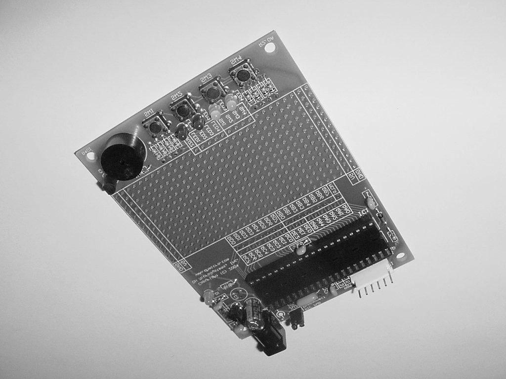
2 Description This is a PCB designed to facilitate the rapid prototyping of a device based on a 40 pin Microchip PIC microcontroller. To allow users to focus on their application, we take care of key housekeeping tasks associated with a microcontroller-based device. To this end, our PCB features several power supply options, a 40 pin footprint for the microcontroller, and several oscillator options. This board also supports in-circuit programming with a dedicated ICSP header. Users can construct their application circuit in our generous a generous prototyping area with space available for several IC s and /or numerous discrete components. To further simplify the construction of prototype PIC devices, on the end of the PCB opposite from the microcontroller and power supply we have provided several common I/O components. There are 4 push buttons, 4 LEDs, and a buzzer that can be configured for use with the prototype application. This board is constructed as a 2-layer throughhole board with clearly marked components on its silkscreen layer, and ample space between components so population of the board can be done by anyone with basic soldering skills. Additional Resources Numerous sources of information are available for both beginning and advanced users. Microchip Technology Inc. manufactures the PIC microcontroller line. Their website can be found at It contains datasheets for all of their microcontrollers, app-notes, and code samples for a variety of applications. Another excellent on-line resource for Microchip PIC development is the Piclist at It contains project info, code examples, and links to PIC related sites. Beginner users might also consider the books published by Square 1 Electronics. They can be found at This list is by no means comprehensive. Many other excellent websites and publications are available and this list is only intended as a starting point for the beginner. Features General: Overall board dimensions 3.00 x PCB is a 2-layer board with solder masks on both sides and a silk screen graphic. 26 x 14 pin prototyping area (364 pins total). Power and GND bus lines run the length of the prototyping area on both sides (not included in proto total pin count). All 33 microcontroller port pins and ~MCLR pin brought out to a clearly labeled strip along the top of the prototyping area. ICSP header. 4 corner mounting holes. Microprocessor: Compatible with all MicroChip PIC 40 pin DIP packaged microprocessors. PIC16C64, 65, 662, 67, 74, 765, 77, 774, 620, PIC16F74, 77, 871, 874, 877, PIC18C442, 452, PIC18F442, 452, 448, 458 (and others). Oscillator Options: Crystal or ceramic resonator with external capacitors (DC-20MHz). Ceramic resonator with internal capacitors (DC- 20MHz). RC oscillator. Power Supply Options: Footprints provided for either TO-92 or TO-220 voltage regulators. Footprint provided for DC power receptacle. Power-on LED. User I/O Options: 4 push buttons. 4 LEDs. Piezo buzzer. Requirements In order to assemble and use this board, a user needs to have basic electronic tools and some skill in their usage, and an 40 pin PIC microcontroller and the tools required to write code and program the executable file onto the controller. Additionally, if this board was purchased as a bare PCB, then a number of discrete components are also required to stock it.
3 Board Schematic Construction Partlist: If you purchased this as a kit, then it included the following components: Printed circuit board IC1-40 pin socket X1-4MHz ceramic resonator VREG1-78L05 voltage regulator (TO-92) DC power receptacle JU1-ICSP header JU2-Jumper block with shorting jumper C1-47uF electrolytic capacitor C2, C4, C5,C8, & C9-0.1uF capacitors R1-470 Ohm, 1/8W, resistor R3-10k Ohm, 1/8W, resistor D1-Green LED D2-1N4148 diode
4 Construction (Cont.) Partlist (Cont.): If it was purchased as a kit including parts to complete the user I/O circuitry then it also included: SW1 - SW4-tactile push-button switches LED1 - LED2-red (x2) and yellow (x2) LEDs BUZZ-5V piezo buzzer Q1-2N2222 (TO-92) NPN transistor R4, & R9 - R12-10k Ohm, 1/8W, resistors R5 R8-470 Ohm, 1/8W, resistors Note: parts are not provided to fill all PCB footprints. The user should stock the board appropriately according to the requirements of any particular design (see construction options discussed on the below). Microcontroller Options: This board will support any 40 pin DIP packaged Microchip PIC microcontroller. The pin descriptions depicted in the schematic on the previous page and on our PCBs represent only basic port definitions for each pin. Refer to the Microchip datasheet for all the features and alternate pin definitions for the microcontroller that you select for use. R3, C8, and D2 are attached to the ~MCLR pin (D2 is added for ICSP compatibility). These components can be omitted and a new reset circuit can be constructed in the prototyping area per instructions found in the Microchip datasheet for your microcontroller. ICSP: Note: refer to Microchip datasheets and appnotes for information on the isolation of ICSP related pins. ICSP signals are available on JU1 (refer to the schematic for pin signal assignments). Depending on what PIC is selected for use the PGM pin may be RB3 or RB5; to configure for either short either (not both) position 3 or 5 on the jumper labeled PGM with a short length of component lead left over from the construction of this board. Refer to the Microchip datasheet for the PIC you select for the assignment of the PGM pin. JU2 isolates the PIC from the boards power supply; it should be disconnected when the prototyping board is attached to an ICSP programmer. This jumper eliminates the possibility of excessive loading of the ICSP programmer by other board components or by the users application circuitry. Re-jumper JU2 when the ICSP programmer is disconnected and the board is to be powered via the onboard power supply. If you are not planning on using an ICSP programmer JU1 can be omitted, JU2 can just be permanently shorted with a bit of component lead, and D2 can be replaced with another bit of component lead. Oscillator Options: Several oscillator options are available with this board: ceramic resonator, crystal oscillator, and RC oscillator (kits ship with a 4MHZ ceramic resonator). Pertinent oscillator parts are R2, C6, C7, and X1. Select these components per instructions found in Microchip datasheets for the microcontroller that you select for use. Power Supply Options: This board will support several different voltage regulators in both TO-92 and TO-220 packages (kits ship with a TO-92 78L05) Note: install only one voltage regulator when assembling your board. Keep in mind the current requirements of your circuitry plus the microcontroller when you are selecting an appropriate voltage regulator. Depending on the requirements for the regulator you select, C1, C2, C3, and C4 may or may not be required and their values will vary. Refer to the manufacturers datasheet for your regulator you select for recommendations. A wall adapter can provide power when the DC power receptacle is installed. A 2.1mm ID, 5MM OD DC power plug with a positive center conductor is required. A bench supply can also be used; in this case omit the power receptacle and solder in red and black wires to the pins labeled Vin and GND respectively. Voltage should be VDC. A power-on LED may be installed by stocking R1 and D1 (a green LED).
5 Construction (Cont.) Assembly: Stock parts in their appropriate locations, paying attention to proper component alignment. Solder components to the PCB with a low wattage soldering iron. Lastly, trim off excess leads and clean off flux residue (if required) with an appropriate solvent. Construct your own circuitry in the open prototyping area. Microcontroller pins are accessed through the labeled strip of pins at the top of the proto area; I/O components are accessed through the labeled pins at the bottom. 5V and GND for your circuit is available on both left and right sides of the proto area in labeled strips. Notes Contact Us We maintain a website where you can get information on our products, obtain literature, and download support files. Visit us online at: your technical support questions to support@dhmicro.com. We try to respond to your questions within an hour if it is received Monday through Friday between the hours of 8am to 5pm (Mountain Time). For sales questions or to place an order, direct your s to sales@dhmicro.com. Refer to the order form and price list available on our website for product pricing, shipping rates, payment instructions, and for other info we need to complete your order. Our mailing address: DH MicroSystems, Inc. P.O. Box 2272 Pocatello, ID Disclaimer: DH MicroSystems, Inc. reserves the right to modify its products or literature, or to discontinue any product at any time without prior notice. The customer is responsible for determining the suitability of any device for any application developed using DH MicroSystems, Inc. components.
Rapid40iXL PIC Prototyping PCB User Manual
 Description This is a PCB designed to facilitate the rapid prototyping of a device based on a 40 pin Microchip PIC microcontroller. To allow users to focus on their application, we take care of key housekeeping
Rapid28iXL PIC Prototyping PCB User Manual
 Description Features This is a PCB designed to facilitate the rapid prototyping of a device based on a 28 pin Microchip PIC microcontroller. To allow users to focus on their application, we take care of
KPIC-0818P (V050919) Devices Included in this Data sheet: KPIC-0818P
 Devices Included in this Data sheet: KPIC-0818P") Devices Included in this Data sheet: KPIC-0818P Features: Carefully designed prototyping area Accepts 8 pin PIC12 series micro-controllers Accepts 14 and 18 Pin PIC16 series Accepts some 8,14 and 18 pin
Devices Included in this Data sheet: KPIC-0818P Features: Carefully designed prototyping area Accepts 8 pin PIC12 series micro-controllers Accepts 14 and 18 Pin PIC16 series Accepts some 8,14 and 18 pin
Advanced Lantern 1.0 Kit. Introduction to the Advanced Lantern 1.0 Kit
 Advanced LED Lantern 1.0 Instruction Manual Eastern Voltage Research, LLC Introduction to the Advanced Lantern 1.0 Kit Thank you for purchasing the Advanced Lantern 1.0 Kit. This kit is an advanced microprocessor
QUASAR KIT No DIGITAL DOWN TIMER 99 MIN WITH PIC
 QUASAR KIT No 1173 - DIGITAL DOWN TIMER 99 MIN WITH PIC KIT 1173 is a digital countdown timer based on a micro controller, thus securing reliability and excellent operation under any circumstances. It
Storage Card Interface Kit
 Storage Card Interface Kit for MultiMediaCards(MMC) and Secure Digital Cards (SD) MMSD3K The MMSD3K is complete development kit interfaced to a SD or MMC card. This board ideal for projects that involve
Advanced Strobe 1.0 Kit
 Kit Instruction Manual Eastern Voltage Research, LLC December 2013, Rev 1 1 http://www.easternvoltageresearch.com Kit Introduction to the Kit Thank you for purchasing the Kit. If you are looking for a
Modtronix Engineering Modular Electronic Solutions SBC28DC. Single board computer for 28 pin DIP PICs
 Modtronix Engineering Modular Electronic Solutions Single board computer for 28 pin DIP PICs Table of Contents 1 Introduction...2 2 Features...4 3 Expansion Connectors...5 3.1 Daughter Board Connectors...5
SRI-02 Speech Recognition Interface
 SRI-02 Speech Recognition Interface Data & Construction Booklet The Speech Recognition Interface SRI-02 allows one to use the SR-07 Speech Recognition Circuit to create speech controlled electrical devices.
SK18A. 18 Pins PIC START-UP KIT. User s Manual V1.1. Dec 2007
 SK18A 18 Pins PIC START-UP KIT User s Manual V1.1 Dec 2007 Information contained in this publication regarding device applications and the like is intended through suggestion only and may be superseded
Assembly Instructions (8/14/2014) Your kit should contain the following items. If you find a part missing, please contact NeoLoch for a replacement.
 Your kit should contain the following items. If you find a part missing, please contact NeoLoch for a replacement.") NeoLoch NLT-28P-LCD-5S Assembly Instructions (8/14/2014) Your kit should contain the following items. If you find a part missing, please contact NeoLoch for a replacement. Kit contents: 1 Printed circuit
NeoLoch NLT-28P-LCD-5S Assembly Instructions (8/14/2014) Your kit should contain the following items. If you find a part missing, please contact NeoLoch for a replacement. Kit contents: 1 Printed circuit
AVR-M Rev 5 ASSEMBLY
 AVR-M Rev 5 ASSEMBLY The AVR_M is a very compact self contained Atmel AVR mcu controller board. It includes an onboard serial programmer (via PC com port), an I2C eeprom and can use a Mega163, Mega16 or
AXE Stack 18. BASIC-Programmable Microcontroller Kit. An inexpensive introduction to microcontroller technology for all ability levels
 Ltd AXE Stack 18 BASIC-Programmable Microcontroller Kit a division of An inexpensive introduction to microcontroller technology for all ability levels Free Windows interface software Programmable in BASIC
Transcendent Frequency Counter
 Transcendent Frequency Counter with blue 2 x 16 LCD display This manual will guide you how to assemble, test and operate this frequency counter KIT. Features: The transcendent counter has two input channels
solutions for teaching and learning
 RKP18Motor Component List and Instructions PCB layout Constructed PCB Schematic Diagram RKP18Motor Project PCB Page 1 Description The RKP18Motor project PCB has been designed to use PIC microcontrollers
IR TRANSMITTER BLOK PCB ASSEMBLY INSTRUCTIONS. Copyright EduTek Ltd Rev. 2
 IR TRANSMITTER BLOK PCB ASSEMBLY INSTRUCTIONS Copyright EduTek Ltd Rev. 2 Circuit Details The circuit is shown below with a parts list of components. Check through this list and identify each component.
Storage Card Interface Kit
 Storage Card Interface Kit for MultiMediaCards(MMC) and Secure Digital Cards (SD) MMSD3F The MMSD3K is complete development kit interfaced to a SD or MMC card. This board ideal for projects that involve
SBC45EC. Single board computer for 44 pin PLCC PICs
 Single board computer for 44 pin PLCC PICs Table of Contents 1 Introduction...3 2 Features...4 3 Expansion Connectors...5 3.1 Frontend Connectors...5 3.1.1 Connecting IDC connectors to the Frontend Connector...5
Exclusive 2.5 GHz Frequency Counter
 Exclusive 2.5 GHz Frequency Counter with blue 2 x 16 LCD display This manual will guide you how to assemble, test and tune this frequency counter KIT. Features: Frequency range from 5 MHz to 2.5GHz Factory
Building RoboPIC 18F4550
 RoboPIC 8F4550 Copyright 206 William Henning Building RoboPIC 8F4550 Copyright 206 William Henning RoboPIC 8F4550 build manual v0.90 The most up to date documentation will always be available at: http://www.mikronauts.com/robot-controllers/robopic-8f4550/
Bill of Materials: 8x8 LED Matrix Driver Game PART NO
 8x8 LED Matrix Driver Game PART NO. 2171031 This Game Maker II kit is a game design platform using a single color 8x8 matrix LED without the need for a shift register or expensive Arduino. The kit includes
AKKON USB CONTROLLER BOARD
 TN002 AKKON USB CONTROLLER BOARD USB Microcontroller board with the PIC18F4550 * Datasheet Authors: Gerhard Burger Version: 1.0 Last update: 20.01.2006 File: Attachments: no attachments Table of versions
PIC 28 Pin Board Documentation. Update Version 5.0
 PIC 28 Pin Board Documentation Update 2009.10 Version 5.0 Table of Contents PIC 28 Pin Board Documentation... 1 Table of Contents... 2 Introduction... 3 Circuit Schematic... 4 The following is the Circuit
PIC Dev 14 Through hole PCB Assembly and Test Lab 1
 Name Lab Day Lab Time PIC Dev 14 Through hole PCB Assembly and Test Lab 1 Introduction: The Pic Dev 14 is a simple 8-bit Microchip Pic microcontroller breakout board for learning and experimenting with
DEVBOARD3 DATASHEET. 10Mbits Ethernet & SD card Development Board PIC18F67J60 MICROCHIP
 DEVBOARD3 DATASHEET 10Mbits Ethernet & SD card PIC18F67J60 MICROCHIP Version 1.0 - March 2009 DEVBOARD3 Version 1.0 March 2009 Page 1 of 7 The DEVBOARD3 is a proto-typing board used to quickly and easily
SBC65EC. Ethernet enabled Single Board Computer
 Ethernet enabled Single Board Computer Table of Contents 1 Introduction...2 2 Features...3 3 Daughter Board Connectors...4 3.1 As a Daughter Board...5 3.2 Expansion boards...5 4 Interfaces...5 4.1 Ethernet...5
TDSDB Features. Description
 TDSDB14550 Features Inexpensive development or project board providing quick start up solution. 5v Pic alternative to the 3.3v TDSDB146J50 Mini B USB socket to provide power and USB functionality. 40 pin
8051 Intermidiate Development Board. Product Manual. Contents. 1) Overview 2) Features 3) Using the board 4) Troubleshooting and getting help
 Overview 2) Features 3) Using the board 4) Troubleshooting and getting help") 8051 Intermidiate Development Board Product Manual Contents 1) Overview 2) Features 3) Using the board 4) Troubleshooting and getting help 1. Overview 2. Features The board is built on a high quality FR-4(1.6
8051 Intermidiate Development Board Product Manual Contents 1) Overview 2) Features 3) Using the board 4) Troubleshooting and getting help 1. Overview 2. Features The board is built on a high quality FR-4(1.6
AVR Intermediate Development Board. Product Manual. Contents. 1) Overview 2) Features 3) Using the board 4) Troubleshooting and getting help
 Overview 2) Features 3) Using the board 4) Troubleshooting and getting help") AVR Intermediate Development Board Product Manual Contents 1) Overview 2) Features 3) Using the board 4) Troubleshooting and getting help 1. Overview 2. Features The board is built on a high quality FR-4(1.6
AVR Intermediate Development Board Product Manual Contents 1) Overview 2) Features 3) Using the board 4) Troubleshooting and getting help 1. Overview 2. Features The board is built on a high quality FR-4(1.6
PICado Alpha Development Board V1.0
 V1.0 Bluetooth Transceiver Module HC-05 Four onboard FET power output stage 34 freely assignable I/O pins ICSP interface 2015 Jan Ritschard, All rights reserved. V1.0 Table of Contents 1. Introduction...
Post Tenebras Lab. Written By: Post Tenebras Lab
 Post Tenebras Lab PTL-ino is an Arduino comptaible board, made entirely out of through-hole components. It is a perfect project to learn how to solder and start getting into the world of micro controllers.
Appendix B. Following is a list of topics in this section:
 Elmer 160 In-Circuit Serial Programming Overview In this section This appendix describes how to design a circuit to support In-circuit Serial Programming (ICSP ). In this appendix, only high voltage programming
Dwarf Boards. DB057 : 40-pin controller board
 Dwarf Boards DB057 : 40-pin controller board PICmicro, In-Circuit Serial Programming and ICSP are registered trademarks of Microchip Technology Inc. DB057 for USB PIC DB057 for non-usb PIC Introduction
BUILDING YOUR KIT. For the Toadstool Mega328.
 BUILDING YOUR KIT For the Toadstool Mega328 www.crash-bang.com @crashbang_proto This work is licensed under a Creative Commons Attribution-ShareAlike 4.0 International License. Congratulations! You re
Thank you for purchasing the RGB Multi-MCU base and driver board from SuperTech-IT and TheLEDCube.com
 CONGRATULATIONS Thank you for purchasing the RGB Multi-MCU base and driver board from SuperTech-IT and TheLEDCube.com In this document, MCU means Microcontroller such as the PIC32, ATmega328P, prototype
VG-305A AC Traffic Light Controller Kit
 Galak Electronics Electronic kits and components Website: GalakElectronics.com Email: sales@galakelectronics.com Phone: (302) 832-1978 VG-305A AC Traffic Light Controller Kit Thank you for your purchase
Images Scientific OWI Robotic Arm Interface Kit (PC serial) Article
 Article") Images Scientific OWI Robotic Arm Interface Kit (PC serial) Article Images Company Robotic Arm PC Interface allows real time computer control and an interactive script writer/player for programming and
Images Scientific OWI Robotic Arm Interface Kit (PC serial) Article Images Company Robotic Arm PC Interface allows real time computer control and an interactive script writer/player for programming and
Electronics Construction Manual
 Electronics Construction Manual MitchElectronics 2019 Version 3 04/02/2019 www.mitchelectronics.co.uk CONTENTS Introduction 3 How To Solder 4 Resistors 5 Capacitors 6 Diodes and LEDs 7 Switches 8 Transistors
A Programmer for the 68HC705C8 MicroController Figure 1 PROG05 As Built PROG05 User Guide Version C1 Page 1 of 14
 A Programmer for the 68HC705C8 MicroController Figure 1 PROG05 As Built PROG05 User Guide Version C1 Page 1 of 14 Table of Contents midon design 1. Introduction...3 2. Description...4 3. Construction...5
SBC44EC. Single board computer for 44 pin PLCC PICs
 Single board computer for 44 pin PLCC PICs Table of Contents 1 Introduction...2 2 Features...3 3 Expansion Connectors...4 3.1 Frontend Connectors...4 3.1.1 Connecting IDC connectors to the Frontend Connector...5
RC Tractor Guy Controller V2.1 Assembly Guide
 RC Tractor Guy Controller V. Assembly Guide Features 0 Push button inputs Dual axis thumb sticks with built-in push button Rotary encoders with built-in push button MCU Socket to suit Meduino Mega 560
Electronics Construction Manual
 Electronics Construction Manual MitchElectronics 2018 Version 1 07/05/2018 www.mitchelectronics.co.uk CONTENTS Introduction 3 How To Solder 4 Resistors 5 Capacitors 6 Diodes and LEDs 7 Switches 8 Transistors
8051 Basic Development Board. Product Manual. Contents. 1) Overview 2) Features 3) Using the board 4) Troubleshooting and getting help
 Overview 2) Features 3) Using the board 4) Troubleshooting and getting help") 8051 Basic Development Board Product Manual Contents 1) Overview 2) Features 3) Using the board 4) Troubleshooting and getting help 1. Overview 2. Features The board is built on a high quality FR-4(1.6
8051 Basic Development Board Product Manual Contents 1) Overview 2) Features 3) Using the board 4) Troubleshooting and getting help 1. Overview 2. Features The board is built on a high quality FR-4(1.6
Assembling the Printed Circuit Board for the EDE1200 Robot
 This board receives instructions from either a CBL2, a LabPro or (with an adapter cable) an original CBL. The board has two 595 shift registers (each providing 8 bits of on-board memory) and two EDE1200
RFID: Read and Display V2010. Version 1.1. Sept Cytron Technologies Sdn. Bhd.
 PR8-B RFID: Read and Display V2010 Version 1.1 Sept 2010 Cytron Technologies Sdn. Bhd. Information contained in this publication regarding device applications and the like is intended through suggestion
8 CHANNEL USB RELAY CARD
 8 CHANNEL USB RELAY CARD Use your computer USB port to connect to the outside world. Total solder points: 363 Difficulty level: beginner 1 2 3 4 5 advanced K8090 ILLUSTRATED ASSEMBLY MANUAL H8090IP-1 Features
Morse Code Practice Oscillator
 Features Description Keyer speed range: Limited only by keying source True Sine wave tone output Tone Volume Control Tone Frequency Control Internal Speaker 1/8 External Speaker/Headphone Jack RCA Key
Goal: We want to build an autonomous vehicle (robot)
") Goal: We want to build an autonomous vehicle (robot) This means it will have to think for itself, its going to need a brain Our robot s brain will be a tiny computer called a microcontroller Specifically
Goal: We want to build an autonomous vehicle (robot) This means it will have to think for itself, its going to need a brain Our robot s brain will be a tiny computer called a microcontroller Specifically
Uzebox Kit Assembly Guide
 Uzebox Kit Assembly Guide V1.3 Page 1 of 18 Revision History Version Date Author Description 1.0 01-Nov-2012 A.Bourque Initial release 1.1 6-Nov-2012 A.Bourque Minor corrections 1.2 28-Jan-2014 A.Bourque
PIC Dev 14 Surface Mount PCB Assembly and Test Lab 1
 Name Lab Day Lab Time PIC Dev 14 Surface Mount PCB Assembly and Test Lab 1 Introduction: The Pic Dev 14 SMD is a simple 8-bit Microchip Pic microcontroller breakout board for learning and experimenting
Sierra Radio Systems. HamStack. Project Board Reference Manual V1.0
 Sierra Radio Systems HamStack Project Board Reference Manual V1.0 Welcome HamStack Project Board Reference Manual Revision 1.0.3 2011 George Zafiropoulos, KJ6VU and John Best, KJ6K This guide provides
Educato. Assembly Instructions
 Product Description The Educato is an Arduino compatible board that has about the functionality of the Arduino Uno. It also has the ability, however, to plug into a solderless breadboard and to have all
CLCD1 Serial 1 wire RS232 LCD development board
 CLCD1 Serial 1 wire RS232 LCD development board Can be used with most 14 pin HD44780 based character LCD displays Use with 1,2,3 or 4 line displays. (Four line LCD shown above) Shown assembled with optional
Schematic Diagram: R2,R3,R4,R7 are ¼ Watt; R5,R6 are 220 Ohm ½ Watt (or two 470 Ohm ¼ Watt in parallel)
") Nano DDS VFO Rev_2 Assembly Manual Farrukh Zia, K2ZIA, 2016_0130 Featured in ARRL QST March 2016 Issue Nano DDS VFO is a modification of the original VFO design in Arduino Projects for Amateur Radio by
Nano DDS VFO Rev_2 Assembly Manual Farrukh Zia, K2ZIA, 2016_0130 Featured in ARRL QST March 2016 Issue Nano DDS VFO is a modification of the original VFO design in Arduino Projects for Amateur Radio by
Arduino IDE Geiger Counter
 Arduino IDE Geiger Counter DIY Kit ver. 2.00 RH-K-GK-2-A http://rhelectronics.net 1 This is ver.2.00 second edition of Geiger project based on Arduino IDE manufactured by RH Electronics http://rhelectronics.net
Digital Candle 1.0 Kit
 Kit Instruction Manual Eastern Voltage Research, LLC June 2012, Rev 1 1 http://www.easternvoltageresearch.com Introduction to the Kit Thank you for purchasing the Kit. This kit is definitely a favorite
KDS Channel DMX Controlled Servo Kit
 KDS00801 8-Channel DMX Controlled Servo Kit This is a DMX512-A controlled servo kit using ANSI approved RJ-45 connectors for DMX networks. Power requirements are 8-20 VDC @ 50 ma. The board features an
Breadboard Voltage. Convenient 5V Supply for Breadboard
 Breadboard Voltage Regulator v2.1 Convenient 5V Supply for Breadboard Turn your 6~18VDC Wall Wart adapter into a regulated 5VDC @ 0.5 Ampere supply for your breadboard experiments! Build Time: 20mins Skill
LED Knight Rider. Yanbu College of Applied Technology. Project Description
 LED Knight Rider Yanbu College of Applied Technology Project Description This simple circuit functions as a 12 LED chaser. A single illuminated LED 'walks' left and right in a repeating sequence, similar
PIC-P40 development board Users Manual
 PIC-P40 development board Users Manual All boards produced by Olimex are ROHS compliant Rev.E, February 008 Copyright(c) 008, OLIMEX Ltd, All rights reserved Page INTRODUCTION: PIC-P40 board is development
Display Real Time Clock (RTC) On LCD. Version 1.2. Aug Cytron Technologies Sdn. Bhd.
 On LCD. Version 1.2. Aug Cytron Technologies Sdn. Bhd.") Display Real Time Clock (RTC) On LCD PR12 Version 1.2 Aug 2008 Cytron Technologies Sdn. Bhd. Information contained in this publication regarding device applications and the like is intended through suggestion
Display Real Time Clock (RTC) On LCD PR12 Version 1.2 Aug 2008 Cytron Technologies Sdn. Bhd. Information contained in this publication regarding device applications and the like is intended through suggestion
QRPometer Assembly Manual Copyright 2012 David Cripe NM0S The 4 State QRP Group. Introduction
 QRPometer Assembly Manual Copyright 2012 David Cripe NM0S The 4 State QRP Group Introduction Thank you for purchasing a QRPometer. We hope you will enjoy building it and and find it a useful addition to
solutions for teaching and learning
 RKOneAnalogue Component List and Instructions PCB layout Constructed PCB Schematic Diagram RKOneAnalogue Software Development PCB Page 1 Description The RKOneAnalogue software development PCB has been
LED Sequencer 1.0 / 1.5
 LED Sequencer 1.0 / 1.5 Instruction Manual Eastern Voltage Research, LLC May 2012, Rev 2 1 http://www.easternvoltageresearch.com Introduction to the LED Sequencer 1.0 Thank you for purchasing the LED Sequencer
RKP08 Component List and Instructions
 RKP08 Component List and Instructions PCB layout Constructed PCB RKP08 Scematic RKP08 Project PCB Page 1 Description The RKP08 project PCB has been designed to use PIC microcontrollers such as the Genie
DMX CONTROLLED RELAY K8072
 Total solder points: 167 Difficulty level: beginner 1 2 3 4 5 advanced DMX CONTROLLED RELAY K8072 f the means o ol. y b y la a re 2 protoc Control DMX51 wn well-kno ILLUSTRATED ASSEMBLY MANUAL Total solder
KDR00101 DMX Controlled Relay Kit
 KDR00101 DMX Controlled Relay Kit This is a DMX512-A relay kit using ANSI approved RJ-45 connectors for DMX networks. Power requirements are 12 Vdc @ 100 ma. The relay contact rating is 10 Amp @ 120 or
Digital Flame 1.0 Kit
 Digital Flame 1.0 Kit Instruction Manual Eastern Voltage Research, LLC June 2012, Rev 1 1 http://www.easternvoltageresearch.com Introduction to the Digital Flame 1.0 Kit Thank you for purchasing the Digital
Section 30. In-Circuit Serial Programming (ICSP )
") Section 30. In-Circuit Serial Programming (ICSP ) HIGHLIGHTS This section of the manual contains the following major topics: 30. Introduction... 30-2 30.2 Entering In-Circuit Serial Programming Mode...
Section 30. In-Circuit Serial Programming (ICSP ) HIGHLIGHTS This section of the manual contains the following major topics: 30. Introduction... 30-2 30.2 Entering In-Circuit Serial Programming Mode...
PICAXE EXPERIMENTER BOARD (AXE090)
") (AXE00) Description: The PICAXE experimenter board allows circuits for any size/revision of PICAXE chip ( / / ) to be quickly tested using a prototyping breadboard. The experimenter board provides power
(AXE00) Description: The PICAXE experimenter board allows circuits for any size/revision of PICAXE chip ( / / ) to be quickly tested using a prototyping breadboard. The experimenter board provides power
Good Idea to Working Electronic Model
 Good Idea to Working Electronic Model by Jan H. Lichtenbelt, March 2011 Abstract Seeing an idea manifest itself into a fully working creation is always satisfying, however so many good ideas go to waste
An open-source hardware+software project. For design files and additional documentation, please visit:
 An open-source hardware+software project. For design files and additional documentation, please visit: http://www.evilmadscientist.com/go/diavolino Support: http://www.evilmadscientist.com/forum/ Distributed
K8099 NIXIE CLOCK. * optional enclosure TKOK19 (black) - TKOK17 (white) ** optional plexiglass enlcosure B8099 ILLUSTRATED ASSEMBLY MANUAL
 - TKOK17 (white) ** optional plexiglass enlcosure B8099 ILLUSTRATED ASSEMBLY MANUAL") Total solder points: 230 + 74 Difficulty level: beginner 1 2 3 4 5 advanced NIXIE CLOCK K8099 ** * A unique combination of both vintage and modern electronics ILLUSTRATED ASSEMBLY MANUAL H8099IP-1 * optional
Total solder points: 230 + 74 Difficulty level: beginner 1 2 3 4 5 advanced NIXIE CLOCK K8099 ** * A unique combination of both vintage and modern electronics ILLUSTRATED ASSEMBLY MANUAL H8099IP-1 * optional
Freeze the Dizz Jameco Part No
 Freeze the Dizz Jameco Part No. 2161431 This project is based on a children s arcade game. Twenty LEDs are placed on a ring and each takes turn to light up forming a rotating light spot. If a push-button
BASIC Stamp Activity Board: Features and Specifications
 27905 w / Power Supply 27906 w/o Power Supply BASIC Stamp Activity Board: Features and Specifications The BASIC Stamp Activity Board (BSAC) is a demonstration board for Parallax BASIC Stamp computers (BS1-IC,
KDR00301 DMX Controlled Relay Kit
 KDR00301 DMX Controlled Relay Kit This is a DMX512-A relay kit using ANSI approved RJ-45 connectors for DMX networks. Power requirements are 12 Vdc @ 200 ma. The relay contact rating is 10 Amp @ 120 or
RFX 328p dev/deployment board - Assembly instructions (long version, v1.3, Feb 12, 2015)
") RFX 328p dev/deployment board - Assembly instructions (long version, v1.3, Feb 12, 2015) Author: Mark Pendrith (support@embeddedcoolness.com) Kit overview The RFX 328/nRF24l01+/Proto dev board is a Arduino
RFX 328p dev/deployment board - Assembly instructions (long version, v1.3, Feb 12, 2015) Author: Mark Pendrith (support@embeddedcoolness.com) Kit overview The RFX 328/nRF24l01+/Proto dev board is a Arduino
PICmicro Microcontroller Lite programmer datasheet
 PICmicro Microcontroller Lite programmer datasheet Contents 1. About this document 2. General information 3. Board overview 4. Getting Started 5. Block schematic and description Appendix A. Circuit diagram
Propeller Proto Board (#32212) Propeller Proto Board USB (#32812) Proto Board Accessory Kit (# )
 Propeller Proto Board USB (#32812) Proto Board Accessory Kit (# )") Web Site: www.parallax.com Forums: forums.parallax.com Sales: sales@parallax.com Technical: support@parallax.com Office: (916) 624-8333 Fax: (916) 624-8003 Sales: (888) 512-1024 Tech Support: (888) 997-8267
Web Site: www.parallax.com Forums: forums.parallax.com Sales: sales@parallax.com Technical: support@parallax.com Office: (916) 624-8333 Fax: (916) 624-8003 Sales: (888) 512-1024 Tech Support: (888) 997-8267
UF-3701 Power Board Construction Guide
 Page 1/5 Soldering and Part Placement See the Chapter 3 of the MIT 6270 Manual for information on electronic assembly, including soldering techniques and component mounting. Construction Information All
Assembly Instructions for the KA Electronics Elliptic Equalizer
 Assembly Instructions for the KA Electronics Elliptic Equalizer Install IC sockets Elliptic Equalizer PC Board Stuffing Guide Place the PC Board on the work bench silkscreen side face up. Place twelve
LIN bus board datasheet EB
 LIN bus board datasheet EB027-00-1 Contents 1. About this document... 2 2. General information... 3 3. Board layout... 4 4. Testing this product... 5 5. Circuit description... 7 Appendix 1 Circuit diagram
um-fpu64 Floating Point Coprocessor 28-pin Breakout Board Introduction Bare um-fpu64 28-pin Breakout Board
 Floating Point Coprocessor Breakout Board Introduction The breakout board has all of the required connections, and provides access to all um- FPU64 pins. It can be used as a development board or for permanently
[Note: Power adapter is not included in the kits. Users need to prepare a 9 12 V ( >300mA capacity ) DC power supply]
![[Note: Power adapter is not included in the kits. Users need to prepare a 9 12 V ( >300mA capacity ) DC power supply]](/thumbs/76/74094055.jpg "[Note: Power adapter is not included in the kits. Users need to prepare a 9 12 V ( >300mA capacity ) DC power supply]") 062 LCD Oscilloscope Assembly Notes Applicable Models: 06203KP, 06204KP DN062-18v02 Important Notes 1. Some components shown in the schematic and PCB layout are for options or adjustments. They do not
062 LCD Oscilloscope Assembly Notes Applicable Models: 06203KP, 06204KP DN062-18v02 Important Notes 1. Some components shown in the schematic and PCB layout are for options or adjustments. They do not
AAZ-0914A USB, Blue tooth and Graphic CPU 50MHZ Antenna Analyzer
 Fox Delta Amateur Radio Projects & Kits FD- AAZ-0914A AAZ-0914A USB, Blue tooth and Graphic CPU 50MHZ Antenna Analyzer AAZ- 0914A KIT: USB Standalone, Blue tooth standalone and Graphic CPU capable 50MHZ*
Lab 0: Wire Wrapping Project: Counter Board
 Lab 0: Wire Wrapping Project: Counter Board September 3, 2008 In this experiment, you will build a simple counter circuit that can be plugged into your breadboard. It will provide a set of TTL output signals
Atmel AVR datasheet. Matrix Multimedia Atmel AVR Board EB Contents
 Atmel AVR datasheet Contents 1. About this document 2. General information 3. Board overview 4. Getting Started 5. Block schematic and description Appendix A. Circuit diagram B. Compatible AVR device C.
REN816XB David Haberle 2010 (Dirknerkle)
") REN816XB David Haberle 2010 (Dirknerkle) www.diychristmas.org The REN816XB is a wireless 8 or 16 channel wireless data Christmas light controller. It is based on the Renard SS16 design- it's essentially
REN816XB David Haberle 2010 (Dirknerkle) www.diychristmas.org The REN816XB is a wireless 8 or 16 channel wireless data Christmas light controller. It is based on the Renard SS16 design- it's essentially
*on-board power supply capability limited. External battery should be used for higher power servos.
 Pan and Tilt Decoder II PART NO. Add affordable Pan and Tilt control to your security cameras using the Pan and Tilt Decoder II and the DFRobot DF05BB Tilt/Pan Kit (5kg), Jameco PN 2144518 or the DAGU
Bolero3M Nexus Emulation Adapter 256BGA 176TQ
 _ V1.4 Adapters Bolero3M Nexus Emulation Adapter 256BGA 176TQ Ordering code IA256BGA176TQ-5646C Supported microcontrollers: Freescale MPC5644B, MPC5644C, MPC5645B, MPC5645C, MPC5646B and MPC5646C ST equivalent
Evaluates: EV Kits Requiring SPI/ Parallel to USB Interface. INTF3000 Interface Board. General Description. Quick Start. Benefits and Features
 INTF3000 Interface Board Evaluates: EV Kits Requiring SPI/ Parallel to USB Interface General Description The INTF3000 interface board is designed to facilitate the interfacing of Maxim s evaluation kit
SK40C ENHANCED 40 PINS PIC START-UP KIT. User s Manual V1.3. March 2012
 SK40C ENHANCED 40 PINS PIC START-UP KIT User s Manual V1.3 March 2012 Information contained in this publication regarding device applications and the like is intended through suggestion only and may be
The PUMPKIN LIGHT LED
 The PUMPKIN LIGHT LED PUMPKIN LIGHT LED By Mark McCuller Email: mcculler@mail.com DESIGN SUMMARY The PUMPKIN LIGHT LED By: Mark McCuller The Pumpkin Light LED is a battery-powered device that illuminates
The FED PIC Flex 2 Development Boards
 The FED PIC Flex 2 Development Boards THE FED PIC Flex Development board offers a host for 28 or 40 pin devices and includes LED's, switches, transistor switches, USB interface, serial port, support circuitry,
Build the Machine Science XBoard, with a programmable microcontroller.
 Build the Machine Science XBoard, with a programmable microcontroller. Site: icode Course: Machine Science Guides Book: Assembling the XBoard Printed by: Guest User Date: Monday, May 24, 2010, 10:46 AM
Manual Main PCB Small-MIDI 4
 Index PARTLIST MAIN PCB... 2 INTRODUCTION... 3 GENERAL... 3 THE CIRCUIT... 3 ASSEMBLY KIT... 4 ASSEMBLY OF THE PCB... 4 An important tip...... 4 ASSEMBLY... 4 THE CONNECTORS... 4 Power supply J1... 4 IDC
SharpSky Focuser Construction. SharpSky Focuser. Construction Document V st December 2012 Dave Trewren 1
 SharpSky Focuser Construction Document V0.12 1st December 2012 Dave Trewren 1 Contents 1 General... 3 1.1 Change Record... 3 1.2 References... 3 2 Introduction... 5 3 SharpSky driver installation... 5
Building and using JasperMIDI
 Building and using JasperMIDI Table of Contents Introduction... Bill Of Materials... 2 Building Choices... 3 Construction... 4 Installing in a Jasper enclosure... 5 Standalone use... 6 Using JasperMIDI...
Figure 3.0, Schematic for display application
 Including lighting for model railroad water towers, bridge, runway, running and crossing lights, rolling hardware and storefront dress-up lights are now easy then ever. While there are several kits readily
Propeller Project Board USB (#32810)
") Web Site: www.parallax.com Forums: forums.parallax.com Sales: sales@parallax.com Technical: support@parallax.com Office: (916) 624-8333 Fax: (916) 624-8003 Sales: (888) 512-1024 Tech Support: (888) 997-8267
Web Site: www.parallax.com Forums: forums.parallax.com Sales: sales@parallax.com Technical: support@parallax.com Office: (916) 624-8333 Fax: (916) 624-8003 Sales: (888) 512-1024 Tech Support: (888) 997-8267