MIC A Evaluation Board
|
|
|
- Lenard Alexander
- 6 years ago
- Views:
Transcription
1 75V/4A Hyper Speed Control Synchronous DC/DC Buck Regulator General Description meter and V IN at Vin and GND terminals with voltmeter. Do not apply power until Step 5. The MIC28500 DC/DC regulator operates over an input 2. Connect Load and Monitor Output supply range of 30V to 75V and provides a regulated output at up to 4A of output current. The output voltage is Connect a load to the Vout and GND terminals. The adjustable down to 0.8V with a typical accuracy of ±1%. load can be either a passive (resistive) or an active The switching frequency is adjustable and once adjusted (as in an electronic load) type. A current meter may be the switching frequency remains fairly constant with placed between the Vout terminal and load to monitor changes in input voltage and output load. the output current. Ensure the output voltage is monitored at the Vout terminal. 3. V The basic parameters of the evaluation board are: IN 30V Limiter Circuit To prevent overstressing of the internal top FET of the 1. Input 30V to 75V MIC28500, the minimum input voltage at full load 2. Output 0.8V to 5V at 4A (1), 12V at 2A (2) kHz Switching Frequency (Adjustable 100kHz should be limited to 30V. This is implemented by using external VIN limiter circuit installed on either EN to 500kHz) pin (dash-line block#1) or VDD Pin (dash-line block#2) as shown in the Evaluation board schematic. On the Notes: MIC28500 evaluation board the limiter circuit on EN 1,2. Refer to thermal de-rating curves shown in Typical Characteristics section. Pin is installed, which shuts off the MIC28500 until the input supply voltage reaches 30V. Datasheets and support documentation can be found on Micrel s web site at: om. 4. Enable Input The EN pin has an internal 100k pull-up resistor to Requirements VDD, which allows the output to be turned on when VDD exceeds its UVLO threshold. An EN connector is The MIC28500 evaluation board requires only a single provided on the evaluation board for users to easily power supply with at least 10A current capability. A access the enable feature. Applying an external logic linear regulator, which includes a Zener and an NPN signal on the EN pin to pull it low or using a jumper to transistor, has been installed on the board to provide short the EN pin to GND will shut off the output of the housekeeping (V DD ) for the MIC The output MIC28500 evaluation board. If in certain application load can either be a passive or an active load. the EN needs to be controlled externally the V IN limiter Precautions circuit should be implemented on VDD pin. The MIC28500 evaluation board does not have 5. Turn on the Power reverse polarity protection. Applying a negative Turn on the VIN supply and verify that the output voltage to the PVIN and GND terminals may damage voltage is regulated to 3.3V. the device. The maximum PVIN of the board is rated at 75V. Exceeding 75V on the PVIN could damage the device Getting Started 1. V IN Supply Connect a supply to the Vin and GND terminals, paying careful attention to the polarity and the supply range (30V < V IN < 75V). Monitor I IN with a current Ordering Information Part Number Description MIC A EV Evaluation Board up to 5V Output MIC A EV Evaluation Board 12V Output Hyper Speed Control is a trademark of Micrel, Inc Micrel Inc Fortune Drive San Jose, CA USA tel +1 (408) fax + 1 (408) July 2011 M
2 Features Feedback Resistors The output voltage on the MIC28500 evaluation board, which is preset to 3.3V, is determined by the feedback divider: V OUT R4 = VREF 1 + R BOTTOM where V REF = 0.8V, and R BOTTOM is one of R5, R6, R7, R8, R9, R10, R11, R12, which corresponds to 0.9V, 1.0V, 1.2V, 1.5V, 1.8V, 2.5V, 3.3V, or 5V. Leaving the R BOTTOM open gives a 0. 8V output voltage. All other voltages not listed above can be set by modifying R BOTTOM value according to: R4 VREF RBOTTOM = VOUT VREF Note that the output voltage should not be set to exceed 5V due to the 6.3V voltage rating on the output capacitors. If higher than 5V output is desired, it is recommended to use the designs shown in Figure 2, where the output capacitors, L1, R3 and R17 are optimized for 12V/2A output. SW Node Test point J11 (VSW) is placed for monitoring the switching waveform, one of the most critical waveforms for the converter. Current Limit The MIC28500 has internal FETs, and the current limit is implemented by sensing the R DS-ON of bottom FET. The MIC28500 has a fixed current limit of 7A (TYP). Loop Gain Measurement The resistor, R13, is placed in series with the regulator feedback path. The control loop gain can be measured by connecting an impedance analyzer across the resistor and selecting the resistor value in between 20Ω to 50Ω. July M
3 MIC V to 5V/4A Evaluation Board Typical Characteristics EFFICIENCY (%) Efficiency (V IN = 48V) vs. Output Current (D02) V IN = 48V f SW = 250kHz 5.0V 3.3V 2.5V 1.8V 1.5V 1.2V 1.0V 0.9V 0.8V Load Current (A) Thermal Derating V OUT = 5V V IN = 30V f SW=250kHz L=10uH V OUT = 3.3V Load Current (A) V OUT = 5V Thermal Derating V IN = 48V f SW =250kHz L=10uH V OUT = 3.3V OUTPUT CURRENT (A) Maximum Ambient Temperature ( C) Maximum Ambient Temperature ( C) Thermal Derating Current (A) Load V IN = 75V f SW =250kHz L=10uH V OUT = 3.3V V OUT = 5V Maximum Ambient Temperature ( C) Die Temperature* : The temperature measurement was taken at the hottest point on the MIC28500 case mounted on a 5 square inch 4 layer, 0.62, FR-4 PCB with 2oz. finish copper weight per layer, see Thermal Measurement section. Actual results will depend upon the size of the PCB, ambient temperature and proximity to other heat emitting components. July M
4 MIC V to 5V/4A Output Evaluation Board Schematic Figure 1. MIC28500 Evaluation board for 0.8V to 5V/4A Output July M
5 Bill of Materials 0.8V to 5V/4A Output Item Part Number Manufacturer Description C1 EEU-FC2A101B Panasonic (1) 100µF Aluminum Capacitor, SMD, 100V 1 C2, C3 C13 C6 C10 C8, C9 C11 C12 C16 C4, C5, C7 Open C14, C15 D1 D2 GRM32ER72A225KA35L Murata C3225X7R2A225KT5 TDK GRM32ER60J107ME20L Murata 12106D107MAT2A AVX 06035C104KAT2A AVX (4) (2) GRM188R71H104KA93D Murata C1608X7R1H104K TDK (4) (2) 2.2µF Ceramic Capacitor, X7R, Size 1210, 100V 2 100µF Ceramic Capacitor, X5R, Size 1210, 6.3V 1 0.1µF Ceramic Capacitor, X7R, Size 0603, 50V 1 GRM188R72A104KA35D Murata 0.1µF Ceramic Capacitor, X7R, Size 0603, 100V 1 C1608X7S2A104K TDK 0805ZC225MAT2A AVX (4) GRM21BR71A225KA01L Murata (2) C2012X7R1A225K TDK (2) GRM188R72A102KA01D Murata C1608X7R2A102K TDK 06031C102KAT2A AVX GRM188R71H472KA01D Murata (2) C1608X7R2A472K TDK 06035C472KAT2A AVX (4) (4) 2.2µF Ceramic Capacitor, X7R, Size 0805, 10V 2 1nF Ceramic Capacitor, X7R, Size 0603, 100V 1 4.7nF Ceramic Capacitor, X7R, Size 0603, 50V 1 GRM21BR71A105KA01L Murata (2) 1µF Ceramic Capacitor, X7R, Size 0805, 10V C2012X7R1A105K TDK 1 Open BAT46W-TP MCC (5) Small Signal Schottky Diode 1 BAT46W-7-F Diodes Inc. (6) MMXZ5232B-TP MCC (5) CMDZ5L6 Central Semi (7) 5.6V Zener Diode 1 D5 CMDZ24L-MIC Central Semi (7) 24V Zener Diode 1 D6 CMDZ3L6-MIC Central Semi (7) 3.6V Zener Diode 1 D4 Open L1 DR R Cooper Bussmann (8) 10µH Inductor, 5.35A RMS, 7A Saturation Current 1 Q1 FCX493 Diodes Inc/ZETEX (6) 100V NPN Transistor 1 R1 CRCW06034R75FKEA Vishay Dale (9) 4.75Ω Resistor, Size 0603, 1% 1 R2, R16 CRCW08051R21FKEA Vishay Dale (9) 1.21Ω Resistor, Size 0805, 1% 2 R3 CRCW060319K6FKEA Vishay Dale (9) 19.6kΩ Resistor, Size 0603, 1% 1 R4 CRCW060310K0FKEA Vishay Dale (9) 10kΩ Resistor, Size 0603, 1% 1 R5 CRCW060380K6FKEA Vishay Dale (9) 80.6kΩ Resistor, Size 0603, 1% 1 Qty. July M
6 Bill of Materials 0.8V to 5V/4A Output (Continued) R6 CRCW060340K2FKEA Vishay Dale (9) 40.2kΩ Resistor, Size 0603, 1% 1 (9) R7 CRCW060320K0FKEA Vishay Dale 20kΩ Resistor, Size 0603, 1% 1 R8 CRCW060311K5FKEA Vishay Dale (9) 11.5kΩ Resistor, Size 0603, 1% 1 R9 CRCW06038K06FKEA Vishay Dale (9) 8.06kΩ Resistor, Size 0603, 1% 1 R10, R23 CRCW06034K75FKEA Vishay Dale (9) 4.75kΩ Resistor, Size 0603, 1% 2 (9) R11 CRCW06033K24FKEA Vishay Dale 3.24kΩ Resistor, Size 0603, 1% 1 R12 CRCW06031K91FKEA Vishay Dale (9) 1.91kΩ Resistor, Size 0603, 1% 1 R13, R24 CRCW Z0EAHP Vishay Dale (9) 0Ω Resistor, Size R14 CRCW080510K0JNEA Vishay Dale (9) 10kΩ Resistor, Size 0805, 1% 1 (9) R15 CRCW060349R9FKEA Vishay Dale 49.9Ω Resistor, Size 0603, 1% 1 R17 (OPEN) CRCW RFKEA Vishay Dale (9) 715Ω Resistor, Size 0603, 1% R18, R19 CRCW KFKEAHP Vishay Dale (9) 100kΩ Resistor, Size 0603, 1% 2 R20 CRCW06032R00FKEA Vishay Dale (9) 2Ω Resistor, Size 0603, 1% 1 R21 (OPEN) CRCW060333K2FKEA Vishay Dale (9) 33.2kΩ Resistor, Size 0603, 1% R22 CRCW060336K5FKEA Vishay Dale (9) 36.5kΩ Resistor, Size 0603, 1% 1 U1 MIC28500YJL Micrel. Inc. (10) 75V/4A Synchronous Buck DC-DC Regulator 1 Notes: 1. Panasonic: 2. Murata: 3. TDK: 4. AVX: 5. MCC: 6. Diode Inc.: 7. Central Semi: 8. Cooper: 9. Vishay: Micrel, Inc.: July M
7 MIC V/2A Output Evaluation Board Typical Characteristics Efficiency vs.output Current Thermal Derating 2 EFFICIENCY (% VIN 75VIN 48VIN Load Current (A) V OUT = 12V f SW =250kHz L=33μH V IN = 48V V IN = 30V 10 V IN = 75V Load Current (A) Maximum Ambient Temperature ( C) Die Temperature* : The temperature measurement was taken at the hottest point on the MIC28500 case mounted on a 5 square inch 4 layer, 0.62, FR-4 PCB with 2oz. finish copper weight per layer, see Thermal Measurement section. Actual results will depend upon the size of the PCB, ambient temperature and proximity to other heat emitting components. July M
8 MIC V/2A Output Evaluation Board Schematic Figure 2. MIC28500 Evaluation board for 12V/2A Output July M
9 Bill of Materials 12V/2A Output Item Part Number Manufacturer Description C1 EEU-FC2A101B Panasonic (1) 100µF Aluminum Capacitor, SMD, 100V 1 C2, C3 C13 C6 C10 C8, C9 C11 C12 C16 C4, C5, C7 Open C14, C15 D1 D2 GRM32ER72A225KA35L Murata C3225X7R2A225KT5 TDK GRM32ER61C476ME15 Murata (2) EMK325BJ476MM-T Taiyo Yuden 06035C104KAT2A AVX (5) (2) GRM188R71H104KA93D Murata C1608X7R1H104K TDK GRM188R72A104KA35D Murata (2) (2) (4) 2.2µF Ceramic Capacitor, X7R, Size 1210, 100V 2 47µF/16V Ceramic Capacitor, X5R, Size µF Ceramic Capacitor, X7R, Size 0603, 50V 1 C1608X7S2A104K TDK 0.1µF Ceramic Capacitor, X7R, Size 0603, 100V ZC225MAT2A AVX (5) GRM21BR71A225KA01L Murata (2) C2012X7R1A225K TDK (2) GRM188R72A102KA01D Murata C1608X7R2A102K TDK 06031C102KAT2A AVX GRM188R71H472KA01D Murata (2) C1608X7R2A472K TDK 06035C472KAT2A AVX (5) (5) 2.2µF Ceramic Capacitor, X7R, Size 0805, 10V 2 1nF Ceramic Capacitor, X7R, Size 0603, 100V 1 4.7nF Ceramic Capacitor, X7R, Size 0603, 50V 1 GRM21BR71A105KA01L Murata (2) 1µF Ceramic Capacitor, X7R, Size 0805, 10V 1 C2012X7R1A105K TDK Open BAT46W-TP MCC (6) Small Signal Schottky Diode 1 BAT46W-7-F Diodes Inc. (7) MMXZ5232B-TP MCC (6) CMDZ5L6 Central Semi (8) 5.6V Zener Diode 1 D5 CMDZ24L-MIC Central Semi (8) 24V Zener Diode 1 D6 CMDZ3L6-MIC Central Semi (8) 3.6V Zener Diode 1 D4 Open L1 DR R Cooper Bussmann (9) 33µH Inductor, 3.28A RMS, 3.84A Saturation Current 1 Q1 FCX493 Diodes Inc/ZETEX (7) 100V NPN Transistor 1 R1 CRCW06034R75FKEA Vishay Dale (10) 4.75Ω Resistor, Size 0603, 1% 1 R2, R16 CRCW08051R21FKEA Vishay Dale (10) 1.21Ω Resistor, Size 0805, 1% 2 R3 CRCW060319K6FKEA Vishay Dale (10) 90.9kΩ Resistor, Size 0603, 1% 1 R4 CRCW060310K0FKEA Vishay Dale (10) 10kΩ Resistor, Size 0603, 1% 1 Qty. July M
10 Bill of Materials 12V/2A Output (Continued) Item Part Number Manufacturer Description R5 (Open) CRCW060380K6FKEA Vishay Dale (10) 80.6kΩ Resistor, Size 0603, 1% R6 (Open) CRCW060340K2FKEA Vishay Dale (10) 40.2kΩ Resistor, Size 0603, 1% R7 (Open) CRCW060320K0FKEA Vishay Dale (10) 20kΩ Resistor, Size 0603, 1% R8 (Open) CRCW060311K5FKEA Vishay Dale (10) 11.5kΩ Resistor, Size 0603, 1% (10) R9 (Open) CRCW06038K06FKEA Vishay Dale 8.06kΩ Resistor, Size 0603, 1% R10 (Open) CRCW06034K75FKEA Vishay Dale (10) 4.75kΩ Resistor, Size 0603, 1% R23 CRCW06034K75FKEA Vishay Dale (10) 4.75kΩ Resistor, Size 0603, 1% 1 R11 (Open) CRCW06033K24FKEA Vishay Dale (10) 3.24kΩ Resistor, Size 0603, 1% (10) R12 (Open) CRCW06031K91FKEA Vishay Dale 1.91kΩ Resistor, Size 0603, 1% R13, R24 CRCW Z0EAHP Vish ay Dale (10) 0Ω Resistor, Size R14 CRCW080510K0JNEA Vishay Dale (10) 10kΩ Resistor, Size 0805, 1% 1 R15 CRCW060349R9FKEA Vishay Dale (10) 49.9Ω Resistor, Size 0603, 1% 1 (10) R17 CRCW RFKEA Vish ay Dale 715Ω Resistor, Size 0603, 1% 1 R18, R19 CRCW KFKEAHP Vishay Dale (10) 100kΩ Resistor, Size 0603, 1% 2 R20 CRCW06032R00FKEA Vishay Dale (10) 2Ω Resistor, Size 0603, 1% 1 R21 (OPEN) CRCW060333K2FKEA Vishay Dale (10) 33.2kΩ Resistor, Size 0603, 1% R22 CRCW060336K5FKEA Vishay Dale (10) 36.5kΩ Resistor, Size 0603, 1% 1 R23 CRCW06034K75FKEA Vishay Dale (10) 4.75kΩ Resistor, Size 0603, 1% 1 U1 MIC28500YJL Micrel. Inc. (11) 75V/4A Synchronous Buck DC-DC Regulator 1 Notes: 1. Panasonic: 2. Murata: m. 3. TDK: 4. Taiyo Yuden: 5. AVX: 6. MCC: 7. Diodes Inc.: 8. Central Semi: 9. Cooper: Vishay: Micrel, Inc.: Qty. July M


 July 2011")
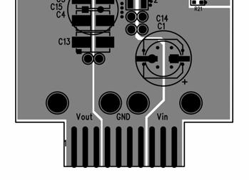
11 Evaluation Board PCB Layout MIC28500 Evaluation Board Silkscreen Top MIC28500 Evaluation Board Copper Layer 1 (Top) July M

12 Evaluation Board PCB Layout (Continued) MIC28500 Evaluation Board Copper Layer 2 MIC28500 Evaluation Board Copper Layer 3 July M
 MIC28500 Evaluation Board")

13 Evaluation Board PCB Layout (Continued) MIC28500 Evaluation Board Copper Layer 4 MIC28500 Evaluation Board Silkscreen Bottom July M
14 MICREL, INC FORTUNE DRIVE SAN JOSE, CA USA TEL +1 (408) FAX +1 (408) WEB Micrel makes no representations or warranties with respect to the accuracy or completeness of the information furnished in this data sheet. This information is not intended as a warranty and Micrel does not assume responsibility for its use. Micrel reserves the right to change circuitry, specifications and descriptions at any time without notice. No license, whether express, implied, arising by estoppel or otherwise, to any intellectual property rights is granted by this document. Except as provided in Micrel s terms and conditions of sale for such products, Micrel assumes no liability whatsoever, and Micrel disclaims any express or implied warranty relating to the sale and/or use of Micrel products including liability or warranties relating to fitness for a particular purpose, merchantability, or infringement of any patent, copyright or other intellectual property right. Micrel Products are not designed or authorized for use as components in life support appliances, devices or systems where malfunction of a product can reasonably be expected to result in personal injury. Life support devices or systems are devices or systems that (a) are intended for surgical implant into the body or (b) support or sustain life, and whose failure to perform can be reasonably expected to result in a significant injury to the user. A Purchaser s use or sale of Micrel Products for use in life support appliances, devices or systems is a Purchaser s own risk and Purchaser agrees to fully indemnify Micrel for any damages resulting from such use or sale Micrel, Incorporated. July M
MIC24051 Evaluation Board
 6A, High-Efficiency, Synchronous DC/DC Buck Regulator with Hyper Speed Control SuperSwitcher II General Description The MIC2451 DC/DC synchronous buck regulator operates over an input supply range of 4.5V
MIC2253 Evaluation Board
 3.5A MHz High Efficiency Boost Regulator with OVP and Softstart General Description The MIC2253 is a high power density MHz PWM DC/DC boost regulator. The 3.5A minimum switch current limit combined with
MIC5165YMM Evaluation Board
 MIC5165YMM Evaluation Board Dual Regulator Controller for DDR3, GDDR3/4/5 Memory Termination Power Good Signal General Description The MIC5165 is a dual regulator controller for high-speed bus termination
MIC5282. General Description. Features. Applications. Typical Applications. 120V IN, 50mA, Ultra-Low I Q, High-PSRR Linear Regulator
 12V IN, 5mA, Ultra-Low I Q, High-PSRR Linear Regulator General Description The high-performance linear regulator offers a very-wide input operating voltage range, up to 12V DC, and supplies an output current
Features. Applications. Regulator with Adjustable Output
 Low-Quiescent Current 150mA LDO Regulator General Description The is a low-quiescent current, μcap lowdropout regulator. With a maximum operating input voltage of 30V and quiescent current of 20μA, it
MIC5281. Features. General Description. Applications. Typical Application. 120V IN, 25mA, Ultra-Low IQ, High-PSRR Linear Regulator
 120V IN, 25mA, Ultra-Low IQ, High-PSRR Linear Regulator General Description The high-performance linear regulator offers a very-wide input operating voltage range, up to 120V DC, and supplies an output
MAQ5281. Features. General Description. Applications. Typical Applications. 120V IN, 25mA, Ultra-Low I Q, High-PSRR Linear Regulator Automotive
 120V IN, 25mA, Ultra-Low I Q, High-PSRR Linear Regulator Automotive General Description The high-performance linear regulator offers a very-wide input operating voltage range, up to 120V DC, and supplies
MAQ5282. Features. General Description. Applications. Typical Applications. 120V IN, 50mA, Ultra-Low I Q, High-PSRR Linear Regulator Automotive
 12V IN, 5mA, Ultra-Low I Q, High-PSRR Linear Regulator Automotive General Description The high-performance linear regulator offers a very-wide input operating voltage range, up to 12V DC, and supplies
MIC2790/1/3. General Description. Features. Applications. Typical Application
 Supervisor with High-Accuracy, Ultra-Fast Propagation Delay, and Capacitor-Programmable Reset Delay General Description The is ideal for monitoring highly-accurate core voltages that require rapid response
MIC2790/1/3. General Description. Features. Applications. Typical Application
 Supervisor with High-Accuracy, Ultra-Fast Propagation Delay, and Capacitor-Programmable Reset Delay General Description The is ideal for monitoring highly-accurate core voltages that require rapid response
Features. Applications
 Push-Button Reset IC General Description The are low-current, ultra-small, pushbutton reset supervisors with long set-up delays. The devices feature two manual reset inputs and two reset outputs. The devices
MIC2782. General Description. Features. Applications. Typical Application. Dual-Input Push Button Reset IC with Immediate and Delayed Outputs
 Dual-Input Push Button Reset IC with Immediate and Delayed Outputs General Description The is a two input, two output push button reset IC. It will generate a reset pulse for a factory programmed reset
Features. LOAD SWITCH or PMIC. LOAD SWITCH or PMIC /RESET
 Dual-Input Push Button Reset IC with Immediate and Delayed Outputs General Description The is a two input, two output push-button reset IC. It will generate a reset pulse for a factory-programmed reset
MIC2039. General Description. Features. Applications. Typical Application. High-Accuracy, High-Side, Adjustable Current Limit Power Switch
 MIC239 High-Accuracy, High-Side, Adjustable Current Limit Power Switch General Description The MIC239 is a high-side MOSFET power distribution switch providing increased system reliability by using 5%
Features. Applications
 HCSL-Compatible Clock Generator for PCI Express General Description The is the smallest, high performance, lowest power, 2 differential output clock IC available for HCSL timing applications. offers -130dBc
MIC2587 Evaluation Board
 MIC2587 Evaluation Board Single Channel, Positive Voltage Hot Swap Controller General Description MIC2587/MIC2587R Hot Swap Controller The MIC2587 is a single-channel, positive voltage hot swap controller
Features. Applications
 Push-Button Reset IC with Voltage Supervisor General Description The are low-current, ultra-small, pushbutton supervisor reset ICs with an integrated supply voltage monitor. The device features two manual
Features. Applications
 Ultra-Precision 1:8 CML Fanout Buffer with Internal I/O Termination General Description The is a 2.5V/3.3V precision, high-speed, fully differential CML 1:8 fanout buffer. The is optimized to provide eight
MIC826. General Description. Features. Applications. Typical Application
 Voltage Supervisor with Watchdog Timer, Manual Reset, and Dual Outputs In 1.6mm x 1.6mm TDFN General Description The is a low-current, ultra-small, voltage supervisor with manual reset input, watchdog
SY89645L. General Description. Features. Block Diagram. Applications. Markets. Precision Low Skew, 1-to-4 LVCMOS/LVTTL-to-LVDS Fanout Buffer
 Precision Low Skew, 1-to-4 LVCMOS/LVTTL-to-LVDS Fanout Buffer General Description The is a 3.3V, fully differential, low skew, 1:4 LVDS fanout buffer that accepts LVTTL or LVCMOS inputs. It is capable
Features. Applications
 3.3V Ultra-Precision 1:4 LVDS Fanout Buffer/Translator with Internal Termination General Description The is a 3.3V, high-speed 2GHz differential low voltage differential swing (LVDS) 1:4 fanout buffer
Figure 1: AAT1106 Evaluation Board.
 Introduction The AAT1106 Evaluation Board contains a fully tested 600mA, 1.5MHz Step-Down DC/DC Regulator. The circuit has an input voltage range of 2.5V to 5.5V and four preset selectable outputs (1.2V,
LM48555 Evaluation Board
 LM48555 Evaluation Board Quick Start Guide 1) Apply power supply voltage to positive terminal of JU4, and source ground to the negative terminal. 2) Short the terminals of JU1 to release the device from
MIC2544A/2548A. General Description. Features. Applications. Typical Application. Programmable Current Limit High-Side Switch
 Programmable Current Limit High-Side Switch General Description The MIC2544A and MIC2548A are integrated, high-side power switches optimized for low loss DC power switching and other power management applications,
Features. Applications
 2.5/3.3V 1-to-1 Differential to LVCMOS/LVTTL Translator Precision Edge General Description Micrel s is a 1-to-1, differential-to-lvcmos / LVTTL translator. The differential input is highly flexible and
Features. Applications
 6GHz, 1:4 CML Fanout Buffer/Translator with Internal I/O Termination General Description The is a 2.5V/3.3V precision, high-speed, fully differential 1:4 CML fanout buffer. Optimized to provide four identical
SM Features. General Description. Applications. Block Diagram
 ClockWorks Fibre Channel (106.25MHz, 212.5MHz) Ultra-Low Jitter, LVDS Frequency Synthesizer General Description The is a member of the ClockWorks family of devices from Micrel and provides an extremely
SM Features. General Description. Typical Application MHz/312.5MHz and MHz/156.25MHz LVDS Clock Synthesizer.
 156.25MHz/312.5MHz and 78.125MHz/156.25MHz LVDS Clock Synthesizer ClockWorks Flex General Description The is a member of the ClockWorks family of devices from Micrel and provides an extremely low-noise
Features. Data Sheet. Micrel Inc Fortune Drive San Jose, CA USA tel +1 (408) fax + 1 (408)
 fax + 1 (408)") Precision Low Power 8:1 MUX with Internal Termination and 1:2 LVPECL Fanout Buffer General Description The SY89859U precision low-power 8:1 MUX with internal termination and 1:2 LVPECL fanout buffer evaluation
Precision Low Power 8:1 MUX with Internal Termination and 1:2 LVPECL Fanout Buffer General Description The SY89859U precision low-power 8:1 MUX with internal termination and 1:2 LVPECL fanout buffer evaluation
Specifications are at T A = 25 C
 Description DC870A is a.5a low dropout linear regulator featuring LT 308. The device is designed for rugged industrial applications and can be paralleled for higher output current or heat spreading. Besides
DEMO MANUAL DC1520A LT3690: 36V/4A µpower Synchronous Buck Regulator DESCRIPTION PERFORMANCE SUMMARY
 DESCRIPTION Demonstration circuit 1520A is a 36V, 4A synchronous Buck Regulator with 70μA Quiescent Current featuring the LT3690. The demo board is designed for 3.3V output from a 4.5V to 36V input with
SM General Description. Features. Block Diagram. ClockWorks TM 125MHz LVDS / 125 MHz HCSL Ultra-Low Jitter Frequency Synthesizer
 ClockWorks TM 125MHz LVDS / 125 MHz HCSL Ultra-Low Jitter Frequency Synthesizer General Description The is a member of the ClockWorks family of devices from Micrel and provides an extremely low-noise timing
MAX5097A Evaluation Kit. Evaluates: MAX5097A
 19-0718; Rev 0; 1/07 MAX5097A Evaluation Kit General Description The MAX5097A evaluation kit (EV kit) demonstrates the MAX5097A in a standard application circuit demonstrating high efficiency. The EV kit
MIC1832. General Description. Features. Applications. Typical Application
 3.3V Voltage Supervisor with Manual Reset, Watchdog Timer and Dual Reset Outputs General Description The is a low-current microprocessor supervisor for monitoring 3.3V and 3V systems. The device features
Features. V CC 2.7V to 5.5V 10k OVERCURRENT GND NC
 MIC225/275 MIC225/275 Single-Channel Power Distribution Switch MM8 General Description The MIC225 and MIC275 are high-side MOSFET switches optimized for general-purpose power distribution requiring circuit
C10, C12, C13, C14, C16. Maxim Integrated Products 1
 9-50; Rev 0; 6/0 MAX968 Evaluation Kit General Description The MAX968 evaluation kit (EV kit) is a fully assembled and tested PC board that implements a switch-mode driver for a Peltier thermoelectric
MIC706P/R/S/T, MIC708R/S/T
 MIC706P/R/S/T, MIC708R/S/T µp Supervisory Circuit General Description The MIC706 and MIC708 are inexpensive microprocessor supervisory circuits that monitor power supplies in 3.0 and 3.3 microprocessor-based
MIC2546/2547. Features. General Description. Applications. Typical Application. Dual Programable Current Limit Switch
 Dual Programable Current Limit Switch General Description The MIC2546 and MIC2547 are integrated high-side dual power switches optimized for low loss dc power switching and other power management applications,
MIC29150/29300/29500/29750
 High-Current Low-Dropout Regulators General Description The are high current, high accuracy, low-dropout voltage regulators. Using Micrel's proprietary Super βeta PNP process with a PNP pass element, these
+Denotes lead-free and RoHS compliant.
 19-2446; Rev 1; 6/08 MAX17062 Evaluation Kit General Description The MAX17062 evaluation kit (EV kit) is a fully assembled and tested surface-mount PCB that provides the voltages required for active-matrix,
Reference Design. 50-W Push-Pull Converter Reference Design Using the UCC38085 (PR100B) Reference Design
 Reference Design") Reference Design 50-W Push-Pull Converter Reference Design Using the UCC38085 (PR100B) Reference Design 1 50-W Push-Pull Converter Reference Design Using the UCC38085 (PR100B) John Bottrill System Power
Reference Design 50-W Push-Pull Converter Reference Design Using the UCC38085 (PR100B) Reference Design 1 50-W Push-Pull Converter Reference Design Using the UCC38085 (PR100B) John Bottrill System Power
Precision CML/LVPECL/LVDS 2:1 MUX with Internal Termination and Fail Safe Input
 Precision CML/LVPECL/LVDS 2:1 MUX with Internal Termination and Fail Safe Input General Description The SY58609U, SY58610U, and SY58611U evaluation boards are designed for convenient setup and quick evaluation
General Description. Features. Component List. Component Suppliers
 General Description The MAX5911 evaluation kit (EV kit) is a fully assembled and tested surface-mount circuit board that demonstrates the MAX5911 fully integrated hot-swap solution for negative supply
Maxim Integrated Products 1
 9-366; Rev ; 2/06 General Description The MAX8727 evaluation kit (EV kit) is a fully assembled and tested surface-mount circuit board that contains a pulse-width-modulated (PWM) step-up DC-DC converter.
EV-110 AAT1157 EVAL 1MHz 1.4A Buck Regulator
 Introduction The AAT1157 evaluation board demonstrates performance, along with the suggested size and placement of external components, for the AAT1157 integrated buck regulator. The external components
MAX16128/MAX16129 Evaluation Kits. Evaluate: MAX16128/MAX General Description. Features. Component List
 General Description The MAX16128/MAX16129 evaluation kits (EV kits) demonstrate high overvoltage protection of the MAX16128/ MAX16129 for automotive applications that must survive load-dump and high-voltage
Features. Applications. MIC4126/27/28 Block Diagram
 Dual 1.5A-Peak Low-Side MOSFET Drivers in Advanced Packaging General Description The MIC4126, MIC4127, and MIC4128 family are highlyreliable dual 1.5A low-side MOSFET drivers fabricated on Micrel s BiCMOS/DMOS
SupIRBuck TM IRDC3891 USER GUIDE FOR IRDC3891 EVALUATION BOARD DESCRIPTION BOARD FEATURES
 IRDC389 SupIRBuck TM USER GUIDE FOR IRDC389 EVUATION BOARD DESCRIPTION The IR389 is a dual synchronous buck converter, providing a compact, high performance and flexible solution in a small 5mm X 6mm Power
Features. Applications
 Micro-Power Voltage Supervisor IttyBitty General Description The is a power supply supervisor that provides undervoltage monitoring, manual reset capability, and power-on reset generation in a compact
MIC705/706/707/708. General Description. Features. Applications. Typical Application. µp Supervisory Circuit
 µp Supervisory Circuit General Description The MIC705, MIC706, MIC707, and MIC708 are inexpensive microprocessor supervisory circuits that monitor power supplies in microprocessor-based systems. The circuit
Development Board EPC9118 Quick Start Guide
 Development Board EPC9118 Quick Start Guide EPC2001C/EPC2021 48 V Buck Converter Revision 1.0 DESCRIPTION The EPC9118 demonstration board is a 5 V output, 400 khz buck converter with a 20 A maximum output
DEMO MANUAL DC1587 LTC3105EDD: Step-Up DC/DC Converter with Power Point Control and LDO Regulator DESCRIPTION
 LTC0EDD: Step-Up DC/DC Converter with Power Point Control and Regulator DESCRIPTION Demonstration circuit 87A is a boost converter optimized for relatively high impedance, very low voltage input power
MIC5159. General Description. Features. Applications. Typical Application. Programmable Current Limit µcap LDO Regulator Controller
 Programmable Current Limit µcap LDO Regulator Controller General Description Micrel s is a precision-voltage regulator controller. Used with an external P-Channel MOSFET, the forms a two-chip low-dropout
2.5Gbps GPON/BPON ONU SERDES
 2.5Gbps GPON/BPON ONU SERDES General Description The SY87725L evaluation board is designed for convenient setup and quick evaluation of the SY87725L using a single power source. The evaluation board is
MAX17105 Evaluation Kit/Evaluation System
 19-4589; Rev 0; 4/09 MAX17105 Evaluation Kit/Evaluation System General Description The MAX17105 evaluation system (EV system) consists of the MAX17105 evaluation kit (EV kit) and the Maxim CMAXQUSB+ command
LMR14050 LMZ20502 LMZ20502
 PMP10743-Test Report Wide V IN, 3 Output Rail Design LMR14050 SIMPLE SWITCHER Converter LMZ20502 SIMPLE SWITCHER Nano Module Overview The reference design below shows the wide input voltage capability,
3.3V DUAL 1:10 PRECISION LVDS FANOUT BUFFER/TRANSLATOR WITH 2:1 INPUT MUX
 3.3V DUAL 1:10 PRECISION LVDS FANOUT BUFFER/TRANSLATOR WITH 2:1 INPUT MUX Precision Edge SY89828L Evaluation Board FEATURES GENERAL DESCRIPTION SY89828L dual 1:10 LVDS fanout buffer Single +3.3V power
S +10.8V to +13.2V Supply Voltage S Output Voltages
 19-5088; Rev 0; 12/09 General Description The MAX17113 evaluation kit (EV kit) is a fully assembled and tested surface-mount PCB that provides the voltages and features required for thin-film transistor
MIC2027/2077. Features. General Description. Applications. Typical Application. Quad USB Power Distribution Switch
 Quad USB Power Distribution Switch General Description The MIC2027 and MIC2077 are quad high-side MOSFET switches optimized for general-purpose power distribution requiring circuit protection. The MIC2027/77
Features VCC MIC1810 RESET RESET
 Microprocessor Reset Circuit General Description The is an inexpensive microprocessor supervisory circuit that monitors power supplies in microprocessor based systems. The function of these devices is
General Description. Features. Related Documentation. Evaluation Board. SY58600/601/602U Evaluation Board
 Ultra-Precision Differential CML and LVPECL Line Driver/Receiver w/internal Termination SY58600/60/60U Evaluation Board General Description The SY58600U, SY5860U and SY5860U evaluation boards are designed
Table 1 summarizes the supported device attribute differences between KSZ9021RN and KSZ9031RNX PHY devices. Device Attribute KSZ9021RN KSZ9031RNX
 to Migration Guide Rev. 1.1 Introduction This document summarizes the hardware pin and software register differences for migrating from an existing board design using the PHY to a new board design using
Features MIC2779L IN OUT HTH GND. Cellular Telephone Battery Monitor
 MIC2779 Voltage Monitor with Adjustable Hysteresis General Description The MIC2779 is a voltage monitor uniquely designed to detect two separate voltage thresholds combined with a delay generator and logic.
LM3881 Power Sequencer Evaluation Board
 LM3881 Power Sequencer Evaluation Board Introduction The LM3881 evaluation board has been designed to permit the designer to connect it directly to the Enable or Remote ON/OFF pins of power supply devices
MIC7401 Evaluation Board
 Configurable PMIC, Five-Channel Buck Regulator plus One-Boost with HyperLight Load, I 2 C Control and Enable General Description The MIC7401 is a powerful, highly-integrated, configurable, power-management
Table 1 summarizes the supported device attribute differences between KSZ9021GN and KSZ9031MNX PHY devices. Device Attribute KSZ9021GN KSZ9031MNX
 to Migration Guide Rev. 1.1 Introduction This document summarizes the hardware pin and software register differences for migrating from an existing board design using the PHY to a new board design using
AN2408 Application note
 Application note 900mA standalone linear Li-Ion battery charger with thermal regulation Introduction One way to minimize the size and complexity of a battery charger is to use a linear-type charger. The
MIC2560. General Description. Features. Applications. Typical Application. PCMCIA Card Socket V CC and V PP Switching Matrix
 PCMCIA Card Socket V CC and V PP Switching Matrix General Description The V CC and V PP Matrix controls PCMCIA (Personal Computer Memory Card International Association) memory card power supply pins, both
LM3410X LED Driver 6-Pin LLP Demo Board
 LM3410X LED Driver 6-Pin LLP Demo Board Introduction The demo board included in this shipment converts 2.7V to 5.5V input, and illuminates four 50mA LED s in series using the LM3410X 1.6MHz LED driver
Maxim Integrated Products 1
 19-2881; Rev 0; 6/03 General Description The MAX1543 evaluation kit (EV kit) is a fully assembled and tested surface-mount circuit board that provides the voltages and features required for active-matrix,
EV1531DQ-002A Low Power, Triple Output Step-Up Plus Charge Pump for TFT Bias
 Monolithic Power Systems EV1531DQ-002A Low Power, Triple Output Step-Up Plus Charge Pump for TFT Bias GENERAL DESCRIPTION The EV1531DQ-002A Evaluation Board is designed to demonstrate the capabilities
Specifications are at T A = 25 C.
 LT3745 16-Channel LED Driver Description Demonstration circuit 1608A features the LT 3745, 16-channel 50mA LED driver with buck controller and serial interface. Each channel has an individually adjustable
Features. o HCSL, LVPECL, or LVDS o Mixed Outputs: LVPECL/HCSL/LVDS. o Ext. Industrial: -40 to 105 C o o. o 30% lower than competing devices
 DSC55704 Crystalless Three Output PCIe Clock Generator General Description The DSC55704 is a Crystalless, three output PCI express clock generator meeting Gen1, Gen2, and Gen3 specifications. The clock
MAX6642 Evaluation System/Evaluation Kit
 19-3417; Rev 0; 9/04 MAX6642 Evaluation System/Evaluation Kit General Description The MAX6642 evaluation kit (EV kit) is an assembled and tested PC board with a mounted MAX6642. The EV kit allows full
MAX8858 Evaluation Kit. Evaluates: MAX8858
 19-4449; Rev 0; 2/09 General Description The MAX8858 evaluation kit (EV kit) is a fully assembled and tested PCB for evaluating the MAX8858 powermanagement IC (PMIC). The MAX8858 PMIC provides a compact
Figure 1: Fully Assembled AAT4621EV Evaluation Kit.
 General Description The AAT4621EV evaluation kit is a fully assembled and tested circuit board designed to demonstrate the features of the AAT4621 SmartSwitch supercapacitor charger. The board accepts
MAX17116Q Evaluation Kit Evaluates: MAX17116 in a 24-Pin TQFN Package
 19-5846; Rev 0; 5/11 MAX17116Q Evaluation Kit General Description The MAX17116Q evaluation kit (EV kit) is a fully assembled and tested surface-mount PCB that evaluates the MAX17116 dual-output DC/DC power
ZXTR21XXEV1 USER GUIDE
 ZXTR1XXEV1 USER GUIDE Description The board is intended for the evaluation of ZXTR1XXF series high voltage 0V linear regulators with fixed 5V, 8V and 1V output voltages in SOT3. Refer to table 1 for detailed
EVALUATION BOARD DATA SHEET EV142
 EV2 Evaluation Board for the AAT272. A Step-Up Current Regulator Introduction The AAT272 EVAL board demonstrates the functionality of the AAT272 and its application as a high current white LED flash driver.
XR76117/21. PowerBlox 15A and 20A Synchronous Step Down COT Regulator GENERAL DESCRIPTION EVALUATION BOARD MANUAL FEATURES
 XR76117/21 November 2016 GENERAL DESCRIPTION The XR76117 and XR76121 are synchronous step-down regulators combining the controller, drivers, bootstrap diode and MOSFETs in a single package for point-of-load
DSC2033. Low-Jitter Configurable Dual LVDS Oscillator. General Description. Features. Block Diagram. Applications
 General Description The series of high performance dual output LVDS oscillators utilize a proven silicon MEMS technology to provide excellent jitter and stability while incorporating additional device
IS31LT3918 T8 Lighting Evaluation Board Guide
 Description Quick Start The IS31LT3918 LED driver IC is a peak current detection buck converter which operates in constant off time mode. It operates over a very wide input voltage supply range of 6VDC
Features. Applications. Micrel Inc Fortune Drive San Jose, CA USA tel +1 (408) fax + 1 (408)
 fax + 1 (408)") Microprocessor Reset Circuits General Description The MIC809 and MIC810 are inexpensive microprocessor supervisory circuits that monitor power supplies in microprocessor-based systems. The function of
Microprocessor Reset Circuits General Description The MIC809 and MIC810 are inexpensive microprocessor supervisory circuits that monitor power supplies in microprocessor-based systems. The function of
Evaluates: MAX14571 MAX MAX14571 Evaluation Kit. General Description. Features. MAX14571 EV Kit Photo
 General Description The MAX14571 evaluation kit (EV kit) demonstrates the MAX14571 adjustable overvoltage and overcurrent protector in a 14-pin TSSOP surface-mount package with an exposed pad. The EV kit
Features MIC2551A VBUS R S. 1.5k D+ D GND VM D SPD SUS GND. Typical Application Circuit
 MIC2551 USB Transceiver General Description The MIC2551 is a single chip transceiver that complies with the physical layer specifications of the Universal Serial Bus (USB) 2.0. It supports both full speed
Micrel Inc Fortune Drive San Jose, CA USA tel +1 (408) fax + 1 (408)
 fax + 1 (408)") DSC2311KL2R008 Crystalless Configurable Clock Generator General Description DSC2311KL2R008 is a crystalless clock generator that is factory configurable to simultaneously output two separate frequencies
DSC2311KL2R008 Crystalless Configurable Clock Generator General Description DSC2311KL2R008 is a crystalless clock generator that is factory configurable to simultaneously output two separate frequencies
IRDCiP1201-A, 300kHz, Dual 15A, 3.14V IN
 REFERENCE DESIGN International Rectifier 33 Kansas Street, El Segundo, CA 95 USA IRDCiP11-A IRDCiP11-A, 3kHz, Dual 15A, 3.V IN to 5.5V IN Dual Output Synchronous Buck Converter using ip11 Overview The
ZLED7030KIT-D1 Demo Kit Description
 ZLED7030KIT-D Demo Kit Description Kit Important Notice Restrictions in Use IDT s ZLED7030KIT-D Demo Kit hardware is designed for ZLED7030 demonstration, evaluation, laboratory setup, and module development
DEMO MANUAL DC1786A LTC2871IUHF RS232/RS485 Multiprotocol Transceiver with Integrated Termination DESCRIPTION QUICK START PROCEDURE
 DESCRIPTION Demonstration circuit 1786A showcases the LTC2871 RS232/RS485 multiprotocol transceiver with integrated termination. Separate supply inputs power the interface and logic sections, permitting
February 2003 PMP EVMs SLVU081
 User s Guide February 2003 PMP EVMs SLVU081 IMPORTANT NOTICE Texas Instruments Incorporated and its subsidiaries (TI) reserve the right to make corrections, modifications, enhancements, improvements, and
Control Circuitry 2 M1. Micrel Inc Fortune Drive San Jose, CA USA tel +1 (408) fax + 1 (408)
 fax + 1 (408)") Crystal-less Configurable Clock Generator General Description The is a programmable, high performance dual LVDS output oscillator utilizing Micrel's proven silicon MEMS technology to provide excellent
Crystal-less Configurable Clock Generator General Description The is a programmable, high performance dual LVDS output oscillator utilizing Micrel's proven silicon MEMS technology to provide excellent
DEMO MANUAL DC2016A LTM V IN, 5.4A Buck-Boost μmodule Regulator. Description
 Description Demonstration circuit 216A features the LTM854, a synchronous buck-boost μmodule regulator that accepts input voltages lower, higher or the same as the output, but is also highly efficient
DEMO MANUAL DC1851A LTC2872 Dual Multiprotocol Transceiver with Integrated Termination DESCRIPTION PERFORMANCE SUMMARY
 DESCRIPTION Demonstration circuit 1851A showcases the LTC 2872 RS232/RS485 dual multiprotocol transceiver with integrated termination. Separate supply inputs power the interface and logic sections, permitting
QUICK START GUIDE FOR DEMONSTRATION CIRCUIT DC512B
 LTC4100 DESCRIPTION Demonstration circuit DC512B is a single battery switching step-down charge controller featuring the LTC4100. The recommended input power is 15 to 20V at 3.5A. A two-position jumper
Features. Slot A Address and data lines between logic controller and PCMCIA cards not shown. System Power Supply 12V 3.3V V CC5 IN A V PP OUT
 MIC2564A Dual Serial PCMCIA/CardBus Power Controller General Description The MIC2564A is dual-slot PC Card PCMCIA (Personal Computer Memory Card International Association) and CardBus power controller.
1:4 LVPECL/CML FANOUT BUFFER WITH INTERNAL TERMINATION
 1:4 LVPECL/CML FANOUT BUFFER WITH TERNAL TERMATION Precision Edge SY58020/21/22U EVALUATION BOARD FEATURES DESCRIPTION Precision, fully differential 1:4 fanout buffer family SY58020U 6GHz any diff. input-to-cml
Specifications are at T A = 25 C
 DESCRIPTION The demo circuit 1559A features the LTM8046, a 2kVAC, 2.5W isolated flyback μmodule converter. The demo circuit is designed for a 5V output from a 3.2V to 26V input. The typical current capability
AL5812EV3 User Guide 150mA, 60V Low-side Adjustable Linear LED Driver
 General Description The AL5812 is an adjustable Linear LED driver offering excellent temperature stability and output handling capability. The AL5812 simplifies the design of linear and isolated or non-isolated
DEMO MANUAL DC1205A LT3592: Step-Down 500mA LED Driver with 10:1 Dimming DESCRIPTION
 LT59: Step-Down 500mA LED Driver with 0: Dimming DESCRIPTION Demonstration circuit 05A features the LT59 6V step-down 500mA LED driver with 0: dimming. The demonstration circuit is designed to drive two
MAX6692 Evaluation System/Evaluation Kit
 19-2707; Rev 0; 10/02 MAX6692 Evaluation System/Evaluation Kit General Description The MAX6692 evaluation system (EV system) consists of a MAX6692 evaluation kit (EV kit) and a companion Maxim SMBus interface