Features. Applications
|
|
|
- Agatha Barker
- 6 years ago
- Views:
Transcription
 1:4 fanout buffer optimized for ultra-low skew applications.")
1 3.3V Ultra-Precision 1:4 LVDS Fanout Buffer/Translator with Internal Termination General Description The is a 3.3V, high-speed 2GHz differential low voltage differential swing (LVDS) 1:4 fanout buffer optimized for ultra-low skew applications. Within device skew is guaranteed to be less than 20ps over supply voltage and temperature. The differential input buffer has a unique internal termination design that allows access to the termination network through a VT pin. This feature allows the device to easily interface to different logic standards. A VREF-AC reference is included for AC-coupled applications. The is part of Micrel s high-speed clock synchronization family. For 2.5V applications, the SY89832U provides similar functionality while operating from a 2.5V ±5% supply. For applications that require a different I/O combination, consult the Micrel website at and choose from a comprehensive product line of high-speed, low-skew fanout buffers, translators and clock generators. Datasheets and support documentation are available on Micrel s web site at: Functional Block Diagram Features Guaranteed AC performance over temperature and voltage: DC-to > 2GHz throughput <600ps propagation delay (IN-to-Q) <20ps within-device skew <150ps rise/fall times Ultra-low jitter design: 98fs RMS phase jitter Patented Any-In input termination and VT pin accepts DC- and AC-coupled inputs High-speed LVDS outputs 3.3V power supply operation: Industrial temperature range: -40 C to +85 C Available in 16-pin (3mm 3mm) QFN package Applications Processor clock distribution SONET clock distribution Fibre Channel clock distribution Gigabit Ethernet clock distribution Typical Performance Precision Edge is a registered trademark of Micrel, Inc. Micrel Inc Fortune Drive San Jose, CA USA tel +1 (408) fax + 1 (408) September 10, 2014 Revision 3.0
2 Ordering Information (1) Part Number Package Type Operating Range Package Marking Lead Finish MG QFN-16 Industrial 833L with Pb-Free Bar Line Indicator MG TR (2) QFN-16 Industrial 833L with Pb-Free Bar Line Indicator Notes: 1. Contact factory for die availability. Dice are guaranteed at T A = 25 C, DC Electricals only. 2. Tape and Reel. NiPdAu Pb-Free NiPdAu Pb-Free Pin Configuration 16-Pin 3mm 3mm QFN Pin Description Pin Number Pin Name Pin Function 15, 16 Q0, /Q0 1, 2 Q1, /Q1 3, 4 Q2, /Q2 5, 6 Q3, /Q3 8 EN 9, 12 /IN, IN 10 VREF-AC LVDS Differential Outputs: Normally terminated with 100Ω across the pair (Q, /Q). See LVDS Outputs section. Unused outputs should be terminated with a 100Ω resistor across each pair. This single-ended TTL/CMOS-compatible input functions as a synchronous output enable. The synchronous enable ensures that enable/disable will only occur when the outputs are in a logic LOW state. Note that this input is internally connected to a 25kΩ pull-up resistor and will default to logic HIGH state (enabled) if left open. Differential Inputs: These input pairs are the differential signal inputs to the device. Inputs accept ACor DC-Coupled differential signals as small as 100mV. Each pin of a pair internally terminates to a VT pin through 50Ω. Note that these inputs will default to an intermediate state if left open. Please refer to the Input Interface Applications section for more details. Reference Voltage: These outputs bias to V CC-1.4V.They are used when AC coupling the inputs (IN, /IN). For AC-Coupled applications, connect VREF-AC to VT pin and bypass with 0.01µF low ESR capacitor to V CC. See Input Interface Applications section for more details. Maximum sink/source current is ±1.5mA. Due to the limited drive capability, each VREF-AC pin is only intended to drive its respective VT pin. September 10, Revision 3.0
3 Pin Description (Continued) Pin Number Pin Name Pin Function 11 VT 13 GND 7, 14 VCC Input Termination Center-Tap: Each side of the differential input pair terminates to a VT pin. The VT pins provide a center-tap to a termination network for maximum interface flexibility. See Input Interface Applications section for more details. Ground. GND pins and exposed pad must be connected to the most negative potential of the device ground. Positive Power Supply: Bypass with 0.1µF//0.01µF low ESR capacitors and place as close to each VCC pin as possible. Truth Tables IN /IN EN Q /Q X X 0 0 (3) 1 (3) Note: 3. On next negative transition of the input signal (IN). September 10, Revision 3.0
4 Absolute Maximum Ratings (4) Supply Voltage (V CC ) V to +4.0V Input Voltage (V IN ) to VCC +0.3V LVDS Output Current (I OUT ) mA Input Current Source or Sink Current on (I VT )... ±2mA Maximum Operating Junction Temperature C Lead Temperature (Soldering, 20 s) C Storage Temperature (T S ) C to +150 C Operating Ratings (5) Supply Voltage Range V to +3.6V Ambient Temperature (T A ) C to +85 C Junction Thermal Resistance (6) QFN (θj A ) Still-Air C/W QFN (ΨJ B ) C/W Electrical Characteristics (7) T A = 40 C to +85 C, unless otherwise stated. Symbol Parameter Condition Min. Typ. Max. Units V CC Power Supply Voltage Range V I CC Power Supply Current No load, maximum V CC ma R IN Input Resistance (IN-to-VT) Ω R DIFF-IN Differential Input Resistance (IN-to-/IN) Ω V IH Input HIGH Voltage (IN-to-/IN) 0.1 V CC V V IL Input LOW Voltage (IN-to-/IN) 0.3 V IH 0.1 V V IN Input Voltage Swing (IN-to-/IN) Note 8, see Figure V CC V V DIFF_IN Differential Input Voltage Note 8, see Figure V IIN Input Current (IN, /IN) Note ma V REF-AC Reference Voltage V CC V CC V CC V Notes: 4. Permanent device damage may occur if absolute maximum ratings are exceeded. This is a stress rating only and functional operation is not implied at conditions other than those detailed in the operational sections of this data sheet. Exposure to absolute maximum rating conditions for extended periods may affect device reliability. 5. The data sheet limits are not guaranteed if the device is operated beyond the operating ratings. 6. Package thermal resistance assumes exposed pad is soldered (or equivalent) to the device's most negative potential on the PCB. ψjb and θja values are determined for a 4-layer board in still-air number, unless otherwise stated. 7. The circuit is designed to meet the DC specifications shown in the above table after thermal equilibrium has been established. 8. Due to the internal termination (see "Input Buffer Structure" section) the input current depends on the applied voltages at IN, /IN and VT inputs. Do not apply a combination of voltages that causes the input current to exceed the maximum limit. September 10, Revision 3.0
5 LVDS Outputs DC Electrical Characteristics (9) V CC = 3.3V±10%, R L = 100Ω across the outputs; T A = -40 C to +85 C. Symbol Parameter Condition Min. Typ. Max. Units V OUT Output Voltage Swing See Figure mv V DIFF_OUT Differential Output Voltage Swing See Figure mv V OCM Output Common Mode Voltage V V OCM Change in Common Mode Voltage mv Note: 9. The circuit is designed to meet the DC specifications shown in the above table after thermal equilibrium has been established. LVTTL/CMOS DC Electrical Characteristics (9) V CC = 3.3V±10%, T A = -40 C to +85 C. Symbol Parameter Condition Min. Typ. Max. Units V IH Input HIGH Voltage 2.0 V CC V V IL Input LOW Voltage V I IH Input HIGH Current V I IL Input LOW Current -300 mv AC Electrical Characteristics (10) V CC = 3.3V±10%, R L = 100Ω across the outputs; T A = -40 C to +85 C unless otherwise stated Symbol Parameter Condition Min Typ Max Units f MAX Maximum Frequency V OUT 200mV 2.0 GHz t pd Propagation Delay IN-to-Q V IN < 400mV ps V IN 400mV ps t SKEW Within-Device Skew Note ps Part-to-Part Skew Note ps t S Set-up Time EN to IN, /IN Note ps t H Hold Time EN to IN, /IN Note ps t JITTER Additive Jitter Output = 622MHz Integration Range: 12kHz 20MHz 98 fs t r, t f Output Rise/Fall Times (20% to 80%) At full output swing ps Notes: 10. High-frequency AC parameters are guaranteed by design and characterization. 11. Within device skew is measured between two different outputs under identical input transitions. 12. Part-to-part skew is defined for two parts with identical power supply voltages at the same temperature and no skew at the edges at the respective inputs. 13. Set-up and hold times apply to synchronous applications that intend to enable/disable before the next clock cycle. For asynchronous applications, set-up and hold times do not apply. September 10, Revision 3.0
6 Timing Diagram September 10, Revision 3.0

7 Typical Characteristics V CC = 3.3V, GND = 0V, V IN = 400mV, R L = 100Ω across the outputs; T A = 25 C unless otherwise stated. September 10, Revision 3.0
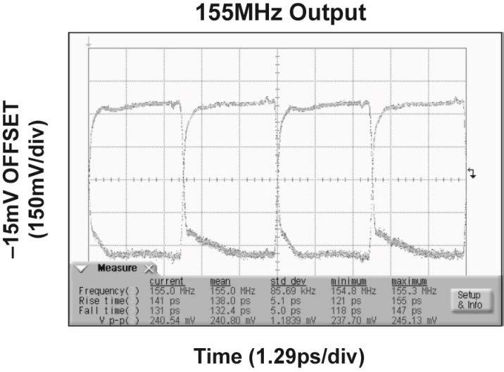
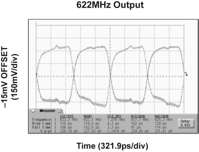
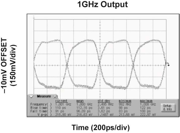
8 Functional Characteristics September 10, Revision 3.0
9 Additive Phase Noise Plot September 10, Revision 3.0
10 Input Stage Figure 1. Simplified Differential Input Buffer LVDS Outputs LVDS specifies a small swing of 325mV typical, on a nominal 1.20V common mode above ground. The common-mode voltage has tight limits to permit large variations in ground noise between a LVDS driver and receiver. Figure 2. LVDS Differential Measurement Figure 3. LVDS Common Mode Measurement Figure 4. Single-Ended Swing Figure 5. Differential Swing September 10, Revision 3.0
11 Input Interface Applications Figure 6. DC-Coupled CML Input Interface Figure 7. AC-Coupled CML Input Interface Figure 8. DC-Coupled LVPECL Input Interface Figure 9. AC-Coupled LVPECL Input Interface Figure 10. LVDS Input Interface Figure 11. AC-Coupled LVDS Input Interface Note: Be certain that the LVDS driver can be AC-coupled. September 10, Revision 3.0
12 Package Information (14) 16-Pin 3mm 3mm QFN (MM) Note: 14. Package information is correct as of the publication date. For updates and most current information, go to September 10, Revision 3.0

13 MICREL, INC FORTUNE DRIVE SAN JOSE, CA USA TEL +1 (408) FAX +1 (408) WEB Micrel, Inc. is a leading global manufacturer of IC solutions for the worldwide high-performance linear and power, LAN, and timing & communications markets. The Company s products include advanced mixed-signal, analog & power semiconductors; high-performance communication, clock management, MEMs-based clock oscillators & crystal-less clock generators, Ethernet switches, and physical layer transceiver ICs. Company customers include leading manufacturers of enterprise, consumer, industrial, mobile, telecommunications, automotive, and computer products. Corporation headquarters and state-of-the-art wafer fabrication facilities are located in San Jose, CA, with regional sales and support offices and advanced technology design centers situated throughout the Americas, Europe, and Asia. Additionally, the Company maintains an extensive network of distributors and reps worldwide. Micrel makes no representations or warranties with respect to the accuracy or completeness of the information furnished in this datasheet. This information is not intended as a warranty and Micrel does not assume responsibility for its use. Micrel reserves the right to change circuitry, specifications and descriptions at any time without notice. No license, whether express, implied, arising by estoppel or otherwise, to any intellectual property rights is granted by this document. Except as provided in Micrel s terms and conditions of sale for such products, Micrel assumes no liability whatsoever, and Micrel disclaims any express or implied warranty relating to the sale and/or use of Micrel products including liability or warranties relating to fitness for a particular purpose, merchantability, or infringement of any patent, copyright, or other intellectual property right. Micrel Products are not designed or authorized for use as components in life support appliances, devices or systems where malfunction of a product can reasonably be expected to result in personal injury. Life support devices or systems are devices or systems that (a) are intended for surgical implant into the body or (b) support or sustain life, and whose failure to perform can be reasonably expected to result in a significant injury to the user. A Purchaser s use or sale of Micrel Products for use in life support appliances, devices or systems is a Purchaser s own risk and Purchaser agrees to fully indemnify Micrel for any damages resulting from such use or sale Micrel, Incorporated. September 10, Revision 3.0
Features. Applications
 6GHz, 1:4 CML Fanout Buffer/Translator with Internal I/O Termination General Description The is a 2.5V/3.3V precision, high-speed, fully differential 1:4 CML fanout buffer. Optimized to provide four identical
Features. Applications
 Ultra-Precision 1:8 CML Fanout Buffer with Internal I/O Termination General Description The is a 2.5V/3.3V precision, high-speed, fully differential CML 1:8 fanout buffer. The is optimized to provide eight
SY89645L. General Description. Features. Block Diagram. Applications. Markets. Precision Low Skew, 1-to-4 LVCMOS/LVTTL-to-LVDS Fanout Buffer
 Precision Low Skew, 1-to-4 LVCMOS/LVTTL-to-LVDS Fanout Buffer General Description The is a 3.3V, fully differential, low skew, 1:4 LVDS fanout buffer that accepts LVTTL or LVCMOS inputs. It is capable
Features. Applications
 2.5/3.3V 1-to-1 Differential to LVCMOS/LVTTL Translator Precision Edge General Description Micrel s is a 1-to-1, differential-to-lvcmos / LVTTL translator. The differential input is highly flexible and
2.5V, 3.2Gbps, DIFFERENTIAL 4:1 LVDS MULTIPLEXER WITH INTERNAL INPUT TERMINATION
 2.5V, 3.2Gbps, DIFFERENTIAL 4:1 LVDS MULTIPLEXER WITH TERNAL PUT TERMATION FEATURES Selects among four differential inputs Guaranteed AC performance over temp and voltage: DC-to > 3.2Gbps data rate throughput
3.3V, 2.0GHz ANY DIFF. IN-TO-LVDS PROGRAMMABLE CLOCK DIVIDER FANOUT BUFFER W/ INTERNAL TERMINATION
 3.3V, 2.0GHz ANY DIFF. -TO-LVDS PROGRAMMABLE CLOCK DIVIDER FANOUT BUFFER W/ TERNAL TERMATION FEATURES Guaranteed AC performance > 2.0GHz f MAX output toggle > 3.0GHz f MAX input < 800ps t PD (matched-delay
3.3V, 3.2Gbps DIFFERENTIAL 4:1 LVDS MULTIPLEXER with INTERNAL INPUT TERMINATION
 3.3V, 3.2Gbps DIFFERENTIAL 4:1 LVDS MULTIPLEXER with TERNAL PUT TERMATION FEATURES Selects among four differential inputs Guaranteed AC performance over temp and voltage: DC-to > 3.2Gbps data rate throughput
SM Features. General Description. Applications. Block Diagram
 ClockWorks Fibre Channel (106.25MHz, 212.5MHz) Ultra-Low Jitter, LVDS Frequency Synthesizer General Description The is a member of the ClockWorks family of devices from Micrel and provides an extremely
SM Features. General Description. Typical Application MHz/312.5MHz and MHz/156.25MHz LVDS Clock Synthesizer.
 156.25MHz/312.5MHz and 78.125MHz/156.25MHz LVDS Clock Synthesizer ClockWorks Flex General Description The is a member of the ClockWorks family of devices from Micrel and provides an extremely low-noise
SM General Description. Features. Block Diagram. ClockWorks TM 125MHz LVDS / 125 MHz HCSL Ultra-Low Jitter Frequency Synthesizer
 ClockWorks TM 125MHz LVDS / 125 MHz HCSL Ultra-Low Jitter Frequency Synthesizer General Description The is a member of the ClockWorks family of devices from Micrel and provides an extremely low-noise timing
MIC705/706/707/708. General Description. Features. Applications. Typical Application. µp Supervisory Circuit
 µp Supervisory Circuit General Description The MIC705, MIC706, MIC707, and MIC708 are inexpensive microprocessor supervisory circuits that monitor power supplies in microprocessor-based systems. The circuit
Features. Applications
 Micro-Power Voltage Supervisor IttyBitty General Description The is a power supply supervisor that provides undervoltage monitoring, manual reset capability, and power-on reset generation in a compact
SY55854U. General Description. Features. Functional Block Diagram. Applications. 2 x 2 Protection Crosspoint Switch
 2 x 2 Protection Crosspoint Switch General Description The is a fully differential, CML, 2 x 2-crosspoint switch. The non-blocking design allows any input to be connected to any output. Varying the state
3.3V 1GHz PRECISION 1:22 LVDS FANOUT BUFFER/TRANSLATOR WITH 2:1 INPUT MUX
 3.3V 1GHz PRECISION 1:22 LVDS FANOUT BUFFER/TRANSLATOR WITH 2:1 INPUT MUX FEATURES High-performance, 1GHz LVDS fanout buffer/ translator 22 differential LVDS output pairs Guaranteed AC parameters over
Features. Applications
 HCSL-Compatible Clock Generator for PCI Express General Description The is the smallest, high performance, lowest power, 2 differential output clock IC available for HCSL timing applications. offers -130dBc
SY89610L. General Description. Features. Applications MHz to 694MHz Jitter Attenuator and Low Phase Noise Frequency Synthesizer
 77.75MHz to 694MHz Jitter Attenuator and Low Phase Noise Frequency Synthesizer General Description The is a 3.3V, fully differential jitter attenuator and frequency synthesizer that accepts a noise clock
Features. Applications. Micrel Inc Fortune Drive San Jose, CA USA tel +1 (408) fax + 1 (408)
 fax + 1 (408)") Microprocessor Reset Circuits General Description The MIC809 and MIC810 are inexpensive microprocessor supervisory circuits that monitor power supplies in microprocessor-based systems. The function of
Microprocessor Reset Circuits General Description The MIC809 and MIC810 are inexpensive microprocessor supervisory circuits that monitor power supplies in microprocessor-based systems. The function of
ANTC205. Introduction
 ANTC205 Introduction The JitterBlocker takes very noisy and jittery clocks and cleans out all the deterministic and excessive jitter. It can handle thousands of picoseconds of period jitter at its input
3.3V 1GHz DUAL 1:10 PRECISION LVDS FANOUT BUFFER/ TRANSLATOR WITH 2:1 INPUT MUX
 3.3V 1GHz DUAL 1:1 PRECISION LVDS FANOUT BUFFER/ TRANSLATOR WITH 2:1 INPUT MUX FEATURES High-performance dual 1:1, 1GHz LVDS fanout buffer/translator Two banks of 1 differential LVDS outputs Guaranteed
MAQ5281. Features. General Description. Applications. Typical Applications. 120V IN, 25mA, Ultra-Low I Q, High-PSRR Linear Regulator Automotive
 120V IN, 25mA, Ultra-Low I Q, High-PSRR Linear Regulator Automotive General Description The high-performance linear regulator offers a very-wide input operating voltage range, up to 120V DC, and supplies
Control Circuitry 2 M1. Micrel Inc Fortune Drive San Jose, CA USA tel +1 (408) fax + 1 (408)
 fax + 1 (408)") Crystal-less Configurable Clock Generator General Description The is a programmable, high performance dual LVDS output oscillator utilizing Micrel's proven silicon MEMS technology to provide excellent
Crystal-less Configurable Clock Generator General Description The is a programmable, high performance dual LVDS output oscillator utilizing Micrel's proven silicon MEMS technology to provide excellent
DSC2033. Low-Jitter Configurable Dual LVDS Oscillator. General Description. Features. Block Diagram. Applications
 General Description The series of high performance dual output LVDS oscillators utilize a proven silicon MEMS technology to provide excellent jitter and stability while incorporating additional device
MAQ5282. Features. General Description. Applications. Typical Applications. 120V IN, 50mA, Ultra-Low I Q, High-PSRR Linear Regulator Automotive
 12V IN, 5mA, Ultra-Low I Q, High-PSRR Linear Regulator Automotive General Description The high-performance linear regulator offers a very-wide input operating voltage range, up to 12V DC, and supplies
MIC826. General Description. Features. Applications. Typical Application
 Voltage Supervisor with Watchdog Timer, Manual Reset, and Dual Outputs In 1.6mm x 1.6mm TDFN General Description The is a low-current, ultra-small, voltage supervisor with manual reset input, watchdog
Micrel Inc Fortune Drive San Jose, CA USA tel +1 (408) fax + 1 (408)
 fax + 1 (408)") DSC2311KL2R008 Crystalless Configurable Clock Generator General Description DSC2311KL2R008 is a crystalless clock generator that is factory configurable to simultaneously output two separate frequencies
DSC2311KL2R008 Crystalless Configurable Clock Generator General Description DSC2311KL2R008 is a crystalless clock generator that is factory configurable to simultaneously output two separate frequencies
Features. o HCSL, LVPECL, or LVDS o Mixed Outputs: LVPECL/HCSL/LVDS. o Ext. Industrial: -40 to 105 C o o. o 30% lower than competing devices
 DSC55704 Crystalless Three Output PCIe Clock Generator General Description The DSC55704 is a Crystalless, three output PCI express clock generator meeting Gen1, Gen2, and Gen3 specifications. The clock
Features. Applications
 Push-Button Reset IC General Description The are low-current, ultra-small, pushbutton reset supervisors with long set-up delays. The devices feature two manual reset inputs and two reset outputs. The devices
Features. Applications. Regulator with Adjustable Output
 Low-Quiescent Current 150mA LDO Regulator General Description The is a low-quiescent current, μcap lowdropout regulator. With a maximum operating input voltage of 30V and quiescent current of 20μA, it
MIC1832. General Description. Features. Applications. Typical Application
 3.3V Voltage Supervisor with Manual Reset, Watchdog Timer and Dual Reset Outputs General Description The is a low-current microprocessor supervisor for monitoring 3.3V and 3V systems. The device features
Control Circuitry 2 M1. Micrel Inc Fortune Drive San Jose, CA USA tel +1 (408) fax + 1 (408)
 fax + 1 (408)") DSC2044FE1H0002 Crystalless Configurable Clock Generator General Description The DSC2044FE1H0002 is a programmable, high performance dual HCSL output oscillator utilizing Micrel's proven silicon MEMS technology
DSC2044FE1H0002 Crystalless Configurable Clock Generator General Description The DSC2044FE1H0002 is a programmable, high performance dual HCSL output oscillator utilizing Micrel's proven silicon MEMS technology
MIC5281. Features. General Description. Applications. Typical Application. 120V IN, 25mA, Ultra-Low IQ, High-PSRR Linear Regulator
 120V IN, 25mA, Ultra-Low IQ, High-PSRR Linear Regulator General Description The high-performance linear regulator offers a very-wide input operating voltage range, up to 120V DC, and supplies an output
DUAL TTL-to-DIFFERENTIAL PECL TRANSLATOR
 DUAL TTL-to-DIFFERENTIAL PECL TRANSLATOR FEATURES DESCRIPTION 300ps typical propagation delay
MIC706P/R/S/T, MIC708R/S/T
 MIC706P/R/S/T, MIC708R/S/T µp Supervisory Circuit General Description The MIC706 and MIC708 are inexpensive microprocessor supervisory circuits that monitor power supplies in 3.0 and 3.3 microprocessor-based
NOT RECOMMENDED FOR NEW DESIGNS SINGLE SUPPLY QUAD PECL/TTL-TO-PECL
 NOT RECOMMENDED FOR NEW DESIGNS Micrel, Inc. SINGLE SUPPLY QUAD PECL/TTL-TO-PECL FEATURES Quad PECL version of popular ECLinPS E Low skew Guaranteed skew spec TTL enable input Selectable TTL or PECL clock
ZL40218 Precision 1:8 LVDS Fanout Buffer
 Precision 1:8 LVDS Fanout Buffer Data Sheet Features Inputs/Outputs Accepts differential or single-ended input LVPECL, LVDS, CML, HCSL, LVCMOS Eight precision LVDS outputs Operating frequency up to 750
MIC5282. General Description. Features. Applications. Typical Applications. 120V IN, 50mA, Ultra-Low I Q, High-PSRR Linear Regulator
 12V IN, 5mA, Ultra-Low I Q, High-PSRR Linear Regulator General Description The high-performance linear regulator offers a very-wide input operating voltage range, up to 12V DC, and supplies an output current
DSC Q0093. General Description. Features. Applications. Block Diagram. Crystal-less Configurable Clock Generator
 Crystal-less Configurable Clock Generator General Description The is a four output crystal-less clock generator. It utilizes Microchip's proven PureSilicon MEMS technology to provide excellent jitter and
Features. Data Sheet. Micrel Inc Fortune Drive San Jose, CA USA tel +1 (408) fax + 1 (408)
 fax + 1 (408)") Precision Low Power 8:1 MUX with Internal Termination and 1:2 LVPECL Fanout Buffer General Description The SY89859U precision low-power 8:1 MUX with internal termination and 1:2 LVPECL fanout buffer evaluation
Precision Low Power 8:1 MUX with Internal Termination and 1:2 LVPECL Fanout Buffer General Description The SY89859U precision low-power 8:1 MUX with internal termination and 1:2 LVPECL fanout buffer evaluation
Precision CML/LVPECL/LVDS 2:1 MUX with Internal Termination and Fail Safe Input
 Precision CML/LVPECL/LVDS 2:1 MUX with Internal Termination and Fail Safe Input General Description The SY58609U, SY58610U, and SY58611U evaluation boards are designed for convenient setup and quick evaluation
MIC2790/1/3. General Description. Features. Applications. Typical Application
 Supervisor with High-Accuracy, Ultra-Fast Propagation Delay, and Capacitor-Programmable Reset Delay General Description The is ideal for monitoring highly-accurate core voltages that require rapid response
MIC2790/1/3. General Description. Features. Applications. Typical Application
 Supervisor with High-Accuracy, Ultra-Fast Propagation Delay, and Capacitor-Programmable Reset Delay General Description The is ideal for monitoring highly-accurate core voltages that require rapid response
Features. Applications
 Push-Button Reset IC with Voltage Supervisor General Description The are low-current, ultra-small, pushbutton supervisor reset ICs with an integrated supply voltage monitor. The device features two manual
VDD = V, TA = -40 C to +85 C, outputs terminated with 100 Ohms between Q and /Q.³
 Ultra-Low Jitter 200MHz LVDS XO ClockWorks FUSION General Description The is an ultra-low phase jitter XO with LVDS output optimized for high line rate applications. Features 200MHz LVDS Typical phase
MIC2782. General Description. Features. Applications. Typical Application. Dual-Input Push Button Reset IC with Immediate and Delayed Outputs
 Dual-Input Push Button Reset IC with Immediate and Delayed Outputs General Description The is a two input, two output push button reset IC. It will generate a reset pulse for a factory programmed reset
1.8V to 3.3V LVCMOS High Performance Clock Buffer Family
 1.8V to 3.3V LVCMOS High Performance Clock Buffer Family 5PB11xx DATASHEET Description The 5PB11xx is a high-performance LVCMOS Clock Buffer Family. It has best-in-class Additive Phase Jitter of 50fsec
Features. LOAD SWITCH or PMIC. LOAD SWITCH or PMIC /RESET
 Dual-Input Push Button Reset IC with Immediate and Delayed Outputs General Description The is a two input, two output push-button reset IC. It will generate a reset pulse for a factory-programmed reset
1:4 LVPECL/CML FANOUT BUFFER WITH INTERNAL TERMINATION
 1:4 LVPECL/CML FANOUT BUFFER WITH TERNAL TERMATION Precision Edge SY58020/21/22U EVALUATION BOARD FEATURES DESCRIPTION Precision, fully differential 1:4 fanout buffer family SY58020U 6GHz any diff. input-to-cml
BLOCK DIAGRAM PIN ASSIGNMENT ICS LOW SKEW, DUAL, 1-TO-5 DIFFERENTIAL- TO-LVDS FANOUT BUFFER PRELIMINARY ICS854210
 LOW SKEW, DUAL, 1-TO-5 DIFFERENTIAL- TO-LVDS FANOUT BUFFER ICS854210 GENERAL DESCRIPTION The ICS854210 is a low skew, high performance ICS dual 1-to-5 Differential-to-LVDS Fanout Buffer HiPerClockS and
Features. Applications. MIC4126/27/28 Block Diagram
 Dual 1.5A-Peak Low-Side MOSFET Drivers in Advanced Packaging General Description The MIC4126, MIC4127, and MIC4128 family are highlyreliable dual 1.5A low-side MOSFET drivers fabricated on Micrel s BiCMOS/DMOS
PCIe 3.0 Clock Generator with 4 HCSL Outputs. Description OE VDDXD S0 S1 S2 X1 X2 PD OE GNDXD IREF CLK0 CLK0 CLK1 CLK1 CLK2 CLK2 CLK3 CLK3
 PCIe 3.0 Clock Generator with 4 HCSL Outputs Features PCIe 3.0 complaint PCIe 3.0 Phase jitter: 0.48ps RMS (High Freq. Typ.) LVDS compatible outputs Supply voltage of 3.3V ±5% 25MHz crystal or clock input
ZL40223 Precision 2:8 LVDS Fanout Buffer with Glitchfree Input Reference Switching and On-Chip Input Termination Data Sheet
 Features Inputs/Outputs Accepts two differential or single-ended inputs LVPECL, LVDS, CML, HCSL, LVCMOS Glitch-free switching of references On-chip input termination and biasing for AC coupled inputs Eight
MIC2560. General Description. Features. Applications. Typical Application. PCMCIA Card Socket V CC and V PP Switching Matrix
 PCMCIA Card Socket V CC and V PP Switching Matrix General Description The V CC and V PP Matrix controls PCMCIA (Personal Computer Memory Card International Association) memory card power supply pins, both
PI6C GHz 1:4 LVPECL Fanout Buffer with Internal Termination GND Q0+ Q0- REF_IN+ V TH V REF-AC REF_IN- Q1+ Q1- Q2+ Q2- Q3+ Q3- VDD.
 Features ÎÎInput Clock Frequency up to 6 GHz Typical ÎÎ4 pairs of differential LVPECL outputs ÎÎLow additive jitter, < 0.05ps (max) ÎÎInput CLK accepts: LVPECL, LVDS, CML, SSTL input level ÎÎOutput to
Differential-to-LVDS Buffer/Divider with Internal Termination
 Differential-to-LVDS Buffer/Divider with Internal Termination IDT8S89872I DATA SHEET General Description The IDT8S89872I is a high speed Differential-to-LVDS Buffer/Divider with Internal Termination. The
Pin Configuration and Selector Guide appear at end of data sheet. Typical Operating Circuits
 Rev 2; 4/08 106.25MHz/212.5MHz/425MHz General Description The DS4106, DS4212, and DS4425 ceramic surfacemount crystal oscillators are part of Maxim s DS4-XO series of crystal oscillators. These devices
3.3V DUAL 1:10 PRECISION LVDS FANOUT BUFFER/TRANSLATOR WITH 2:1 INPUT MUX
 3.3V DUAL 1:10 PRECISION LVDS FANOUT BUFFER/TRANSLATOR WITH 2:1 INPUT MUX Precision Edge SY89828L Evaluation Board FEATURES GENERAL DESCRIPTION SY89828L dual 1:10 LVDS fanout buffer Single +3.3V power
General Description. Features. Related Documentation. Evaluation Board. SY58600/601/602U Evaluation Board
 Ultra-Precision Differential CML and LVPECL Line Driver/Receiver w/internal Termination SY58600/60/60U Evaluation Board General Description The SY58600U, SY5860U and SY5860U evaluation boards are designed
CKSET V CC _VCO FIL SDO+ MAX3952 SCLKO+ SCLKO- PRBSEN LOCK GND TTL
 19-2405; Rev 0; 4/02 10Gbps 16:1 Serializer General Description The 16:1 serializer is optimized for 10.3Gbps and 9.95Gbps Ethernet applications. A serial clock output is provided for retiming the data
Table 1 summarizes the supported device attribute differences between KSZ9021RN and KSZ9031RNX PHY devices. Device Attribute KSZ9021RN KSZ9031RNX
 to Migration Guide Rev. 1.1 Introduction This document summarizes the hardware pin and software register differences for migrating from an existing board design using the PHY to a new board design using
Low Skew, 1-to-16 Differential-to-LVDS Clock Distribution Chip
 Low Skew, 1-to-16 Differential-to-LVDS Clock Distribution Chip ICS8516 DATASHEET GENERAL DESCRIPTION The ICS8516 is a low skew, high performance 1-to-16 Differentialto-LVDS Clock Distribution Chip. The
Table 1 summarizes the supported device attribute differences between KSZ9021GN and KSZ9031MNX PHY devices. Device Attribute KSZ9021GN KSZ9031MNX
 to Migration Guide Rev. 1.1 Introduction This document summarizes the hardware pin and software register differences for migrating from an existing board design using the PHY to a new board design using
ICS548A-03 LOW SKEW CLOCK INVERTER AND DIVIDER. Description. Features. Block Diagram DATASHEET
 DATASHEET ICS548A-03 Description The ICS548A-03 is a low cost, low skew, high-performance general purpose clock designed to produce a set of one output clock, one inverted output clock, and one clock divided-by-two.
DS90LV804 4-Channel 800 Mbps LVDS Buffer/Repeater
 DS90LV804 4-Channel 800 Mbps LVDS Buffer/Repeater General Description The DS90LV804 is a four channel 800 Mbps LVDS buffer/ repeater. In many large systems, signals are distributed across cables and signal
BLOCK DIAGRAM PIN ASSIGNMENT I Data Sheet. Low Skew, 1-to-9 Differential-to-HSTL Fanout Buffer ICS852911I
 Low Skew, 1-to-9 Differential-to-HSTL Fanout Buffer 852911I Data Sheet GENERAL DESCRIPTION The 852911I is a low skew, 1-to-9 Differential-to-HSTL Fanout Buffer. The 852911I has two selectable clock inputs
PI6LC48L0201A 2-Output LVDS Networking Clock Generator
 Features ÎÎTwo differential LVDS output pairs ÎÎSelectable crystal oscillator interface or LVCMOS/LVTTL single-ended clock input ÎÎSupports the following output frequencies: 62.5MHz, 125MHz, 156.25MHz
Features MIC2551A VBUS R S. 1.5k D+ D GND VM D SPD SUS GND. Typical Application Circuit
 MIC2551 USB Transceiver General Description The MIC2551 is a single chip transceiver that complies with the physical layer specifications of the Universal Serial Bus (USB) 2.0. It supports both full speed
MC FPGA Bridge IC. for. MIPI D-PHY Systems and SLVS to LVDS Conversion DATASHEET. Version August Meticom GmbH
 FPGA Bridge IC for MIPI D-PHY Systems and SLVS to LVDS Conversion DATASHEET Version 1.09 August 2016 Meticom GmbH Meticom GmbH Page 1 of 14 Revision History Version Date of Issue Change 1.01 April 25,
MC Channel FPGA Bridge IC. for. MIPI D-PHY Systems and SLVS to LVDS Conversion PRELIMINARY DATASHEET. Version August 2014.
 MC20901 5 Channel FPGA Bridge IC for MIPI D-PHY Systems and SLVS to LVDS Conversion PRELIMINARY DATASHEET Version 1.06 August 2014 Meticom GmbH Meticom GmbH Page 1 of 17 Revision History MC20901 Version
Features VCC MIC1810 RESET RESET
 Microprocessor Reset Circuit General Description The is an inexpensive microprocessor supervisory circuit that monitors power supplies in microprocessor based systems. The function of these devices is
2:1 MULTIPLEXER CHIP FOR PCI-EXPRESS ICS Description. Features. Block Diagram DATASHEET
 DATASHEET 2:1 MULTIPLEXER CHIP FOR PCI-EXPRESS ICS557-08 Description The ICS557-08 is a 2:1 multiplexer chip that allows the user to select one of the two HCSL (Host Clock Signal Level) or LVDS input pairs
ICS8543I. Features. General Description. Pin Assignment. Block Diagram LOW SKEW, 1-TO-4 DIFFERENTIAL-TO-LVDS FANOUT BUFFER
 LOW SKEW, 1-TO-4 DIFFERENTIAL-TO-LVDS FANOUT BUFFER ICS8543I General Description The ICS8543I is a low skew, high performance ICS 1-to-4 Differential-to-LVDS Clock Fan Buffer and a member of the family
2:1 MULTIPLEXER CHIP FOR PCI-EXPRESS ICS Features
 DATASHEET 2:1 MULTIPLEXER CHIP FOR PCI-EXPRESS ICS557-08 Description The ICS557-08 is a 2:1 multiplexer chip that allows the user to select one of the two HCSL (Host Clock Signal Level) input pairs and
MPC9817ENR2. Clock Generator for PowerQUICC and PowerPC Microprocessors and Microcontrollers DATA SHEET NRND
 Clock Generator for PowerQUICC and PowerPC Microprocessors and Microcontrollers MPC9817 DATA SHEET NRND The MPC9817 is a PLL-based clock generator specifically designed for Freescale Semiconductor Microprocessor
PTN3310/PTN3311 High-speed serial logic translators
 INTEGRATED CIRCUITS Supersedes data of 2002 Oct 24 2004 Feb 24 FEATURES Meets LVDS EIA-644 and PECL standards 2 pin-for-pin replacement input/output choices: PIN CONFIGURATIONS GND1 1 8 V CC1 LVDS in,
MIC24051 Evaluation Board
 6A, High-Efficiency, Synchronous DC/DC Buck Regulator with Hyper Speed Control SuperSwitcher II General Description The MIC2451 DC/DC synchronous buck regulator operates over an input supply range of 4.5V
PI6C557-01BQ. PCIe 3.0 Clock Generator with 1 HCSL Outputs. Features. Description. Pin Configuration (16-Pin TQFN) Block Diagram
 Block Diagram") s Features ÎÎPCIe 3.0 compliant à à Phase jitter - 0.45ps RMS (High Freq. Typ.) ÎÎLVDS compatible output ÎÎSupply voltage of 3.3V ±10% ÎÎ25MHz crystal or clock input frequency ÎÎHCSL outputs, 0.8V Current
s Features ÎÎPCIe 3.0 compliant à à Phase jitter - 0.45ps RMS (High Freq. Typ.) ÎÎLVDS compatible output ÎÎSupply voltage of 3.3V ±10% ÎÎ25MHz crystal or clock input frequency ÎÎHCSL outputs, 0.8V Current
2 TO 4 DIFFERENTIAL CLOCK MUX ICS Features
 DATASHEET 2 TO 4 DIFFERENTIAL CLOCK MUX ICS557-06 Description The ICS557-06 is a two to four differential clock mux designed for use in PCI-Express applications. The device selects one of the two differential
Low Skew, 1-to-8, Differential-to-LVDS Clock
 Low Skew, 1-to-8, Differential-to-LVDS Clock 85408 DATA SHEET General Description The 85408 is a low skew, high performance 1-to-8 Differential-to-LVDS Clock Distribution Chip. The 85408 CLK, nclk pair
PI6C GND REF_IN+ V TH V REF-AC REF_IN- Q0+ Q0- Q1+ Q1- VDD. 6 GHz / 12 Gbps Clock / Data Fanout Buffer with Internal Termination.
 Features ÎÎInput Clock Frequency up to 6 GHz Typical ÎÎMaximum Input Data Rate up to 12 Gbps Typical ÎÎ2 pairs of differential CML outputs ÎÎLow additive jitter, < 0.05ps (max) ÎÎInput accepts: CML, LVDS,
Wireless Access Point Server/Storage DIFF1 DIFF2
 PCI-EXPRESS GEN 1, GEN 2, AND GEN 3 1:2 FAN-OUT CLOCK BUFFER Features PCI-Express Gen 1, Gen 2, and Gen 3 compliant devices Two low-power PCIe clock outputs Supports Serial-ATA (SATA) at 100 MHz No termination
Features. Slot A Address and data lines between logic controller and PCMCIA cards not shown. System Power Supply 12V 3.3V V CC5 IN A V PP OUT
 MIC2564A Dual Serial PCMCIA/CardBus Power Controller General Description The MIC2564A is dual-slot PC Card PCMCIA (Personal Computer Memory Card International Association) and CardBus power controller.
DS90LV004 4-Channel LVDS Buffer/Repeater with Pre-Emphasis
 DS90LV004 4-Channel LVDS Buffer/Repeater with Pre-Emphasis General Description The DS90LV004 is a four channel 1.5 Gbps LVDS buffer/repeater. High speed data paths and flow-through pinout minimize internal
MIC2544A/2548A. General Description. Features. Applications. Typical Application. Programmable Current Limit High-Side Switch
 Programmable Current Limit High-Side Switch General Description The MIC2544A and MIC2548A are integrated, high-side power switches optimized for low loss DC power switching and other power management applications,
T1/E1 CLOCK MULTIPLIER. Features
 DATASHEET ICS548-05 Description The ICS548-05 is a low-cost, low-jitter, high-performace clock synthesizer designed to produce x16 and x24 clocks from T1 and E1 frequencies. Using IDT s patented analog/digital
FIN1101 LVDS Single Port High Speed Repeater
 FIN1101 LVDS Single Port High Speed Repeater General Description This single port repeater is designed for high speed interconnects utilizing Low Voltage Differential Signaling (LVDS) technology. It accepts
MIC29150/29300/29500/29750
 High-Current Low-Dropout Regulators General Description The are high current, high accuracy, low-dropout voltage regulators. Using Micrel's proprietary Super βeta PNP process with a PNP pass element, these
TF10CP02 / TF10CP Gbps 2x2 LVDS Crosspoint Switches. Features. Description. Applications. Function Diagram. Ordering Information.
 Features DC to 1.5 Gbps low jitter, low skew, low power operation Pin configurable, fully differential, non-blocking architecture eases system design and PCB layout On-chip 100W input termination minimizes
MIC A Evaluation Board
 75V/4A Hyper Speed Control Synchronous DC/DC Buck Regulator General Description meter and V IN at Vin and GND terminals with voltmeter. Do not apply power until Step 5. The MIC28500 DC/DC regulator operates
PCI EXPRESS Jitter Attenuator
 PCI EXPRESS Jitter Attenuator ICS874003-02 DATA SHEET General Description The ICS874003-02 is a high performance Differential-to- LVDS Jitter Attenuator designed for use in PCI Express systems. In some
MX877RTR. 8-Channel, 60V Driver with Push-Pull Output, 3 Wire Interface INTEGRATED CIRCUITS DIVISION. Features. Description.
 8-Channel, 6V Driver with Push-Pull Output, 3 Wire Interface Features Eight (8) Outputs Rated at 6V, ±8mA Push-Pull Driver Configuration 6V to 6V Driver Supply Range 2.7V to 5.5V Logic Supply Range 3-Wire
MIC2546/2547. Features. General Description. Applications. Typical Application. Dual Programable Current Limit Switch
 Dual Programable Current Limit Switch General Description The MIC2546 and MIC2547 are integrated high-side dual power switches optimized for low loss dc power switching and other power management applications,
E P AP3615. Pin Assignments. Description. Features. Applications 5 CHANNEL CHARGE PUMP CURRENT SINK FOR LED DRIVER AP3615
 AGND PGND VIN EN VOUT1 NC VOUT2 D1 5 CHANNEL CHARGE PUMP CURRENT SINK FOR LED DRIVER Description The is a step-up DC-DC converter based on 1x/1.5x charge pump and low dropout current sink, which helps
1.8 V, 12-LVDS/24-CMOS Output, Low Power Clock Fanout Buffer ADCLK854
 .8 V, 2-LVDS/24-CMOS Output, Low Power Clock Fanout Buffer AD854 FEATURES 2 selectable differential inputs Selectable LVDS/CMOS outputs Up to 2 LVDS (.2 GHz) or 24 CMOS (250 MHz) outputs
CAP+ CAP. Loop Filter
 STS-12/STS-3 Multirate Clock and Data Recovery Unit FEATURES Performs clock and data recovery for 622.08 Mbps (STS-12/OC-12/STM-4) or 155.52 Mbps (STS-3/OC-3/STM-1) NRZ data 19.44 MHz reference frequency
2.5Gbps GPON/BPON ONU SERDES
 2.5Gbps GPON/BPON ONU SERDES General Description The SY87725L evaluation board is designed for convenient setup and quick evaluation of the SY87725L using a single power source. The evaluation board is
MIC2039. General Description. Features. Applications. Typical Application. High-Accuracy, High-Side, Adjustable Current Limit Power Switch
 MIC239 High-Accuracy, High-Side, Adjustable Current Limit Power Switch General Description The MIC239 is a high-side MOSFET power distribution switch providing increased system reliability by using 5%
Features MIC2779L IN OUT HTH GND. Cellular Telephone Battery Monitor
 MIC2779 Voltage Monitor with Adjustable Hysteresis General Description The MIC2779 is a voltage monitor uniquely designed to detect two separate voltage thresholds combined with a delay generator and logic.
FIN1102 LVDS 2 Port High Speed Repeater
 LVDS 2 Port High Speed Repeater General Description This 2 port repeater is designed for high speed interconnects utilizing Low Voltage Differential Signaling (LVDS) technology. The FIN1102 accepts and
PCI EXPRESS Jitter Attenuator
 PCI EXPRESS Jitter Attenuator ICS874003-04 DATA SHEET General Description The ICS874003-04 is a high performance ICS Differential-to-LVDS Jitter Attenuator designed for use HiPerClockS in PCI Express systems.
F USB Charger Controller F Release Date: Dec., 2011 Version: V0.11P. Nov., 2011 Data Sheet
 USB Charger Controller Release Date: Dec., 2011 Version: V0.11P F75204 Datasheet Revision History Version Date Page Revision History Data Brief 2011/10 - Data Brief 0.10P 2011/ 11 Up Date AC/DC SPECs 0.11P