Data. Table of Contents. Rising. Parts and Assembly Guide. 1. Rising Data Hardware Setup Arduino Integration SD Card Integration 3-1
|
|
|
- MargaretMargaret Elliott
- 6 years ago
- Views:
Transcription
1 Rising Data
2 Table of Contents Rising Data Chapters Parts and Assembly Guide 1. Rising Data Hardware Setup 2. Arduino Integration 3. SD Card Integration 4-A. 9DoF Integration 4-B. BME280 Integration 5. TMP-36 Integration 6. Battery Board Integration 7. Building the Payload 8. Building the Rocket Additional Payload Photos Pages Acknowledgement: Funding for the Rising Data program has been provided by NASA s Minority University Research and Education Program #NNX15AV98A. This guide was developed by the Education and Public Outreach group at Sonoma State University, under the direction of Prof. Lynn Cominsky. Questions about this guide should be sent to lynnc@universe.sonoma.edu. Reference: All videos and guides used in Rising Data are linked here: II
.")

 identical pins, and all the documentation provided by the manufacturer is for the 5V version. Don t let this confuse you.")
3 Parts and Assembly Guide Rising Data Parts Arduino Pro Trinket 3V This device provides the processing power for the payload. It uses an ATMega328 Processor that runs regular Arduino C/Processing Code written with the Arduino IDE (Integrated Development Environment). While this device has a USB Port capable of powering the device and loading code, it does NOT have an on-board FTDI chip with which many other Arduinos come equipped. This means that in order to have serial communication with the device, it is necessary to use an FTDI cable instead of a regular USB cable. There are two versions of the Pro Trinket that use 3.3V and 5V for logic levels. For Rising Data, we are using 3.3V, so be careful if ordering additional boards. The 5V has (almost) identical pins, and all the documentation provided by the manufacturer is for the 5V version. Don t let this confuse you. Instructions for testing the Arduino are in sections 1 and 2. MicroSD Card Device This device provides mechanical and electrical connections to the pins on a micro SD card. Unlike other SD breakout boards, this does not provide any kind of integrated processor or logic level conversion. It only provides a mechanical socket for the SD card, and brings the SD card pins out into a DIP mountable format. This device connects to the Arduino over an SPI bus. It allows us to quickly log data as we collect it. The software we provide allows us to write to an SD card formatted FAT16/32, so it can be removed and read as a text file from a regular computer. Instructions for wiring and testing the SD Card are in section 3. 9DoF (Nine Degrees of Freedom) Device This device incorporates three sub-sensors: a 3-axis accelerometer, a 3-axis gyro, and a 3-axis magnetometer. This provides telemetry to analyze after flights. It communicates with the Arduino over an I 2 C interface. Instructions for wiring and testing the 9DoF are in section 4. 1
 and SD card")


4 Protoboard These boards have been custom designed for the Rising Data project. On the top side of the board, there are special areas for soldering the socket that holds the Arduino (upper) and SD card (lower). On the bottom side of the board, the 9DoF and TMP-36 sockets can be soldered in the lower area. There is also room for additional devices in this lower area. Note that there are traces built into the board that connect the power and ground pins for the Arduino to the inside and outside rails, respectively. There are also holes in all four corners of the board that connect to posts to allow the board to become part of the stack that comprises the payload. Some of the posts are connected to ground, and others to 3V power supplied by the battery board. Top Side Bottom Side Lower Upper TMP-36 The TMP-36 is a relatively linear analog device, which means that the voltage it puts out is proportional to the ambient temperature. It has three pins: Power, data and ground. Power Data Female Header Socket We will be attaching all our parts using rows of female header sockets so that parts can be easily attached and removed from the protoboard. These will be soldered to the protoboard (instead of the parts). 2 Ground Flat side with writing


5 Assembly Information Place Socket Put the part through the holes you intend to solder it into. You may also decide to tape the part in place so it doesn t fall out when you pass it off to have it checked or when you move it around to solder it. Wiring Placement First cut the wires to the desired length. You want the wire to fit comfortably between the two pins it connects, but you don t want enough extra slack that it could get snagged when being handled. Be sure to leave about an extra inch past what you need for the next step (stripping the ends). Strip about ½ inch off each end of the wire so you can connect it to the board with solder. After putting the wires through the appropriate holes, fold them over as shown. This will keep them from falling out in the time between placing them and soldering them. For the very short jumper wires used to connect power and ground to the devices, you may find it difficult to strip the wires and leave a tiny bit of insulation in place. Consult the wire stripping help guide on page 4 if you are having trouble. Check Pass the payload to a partner to have them confirm your placement. This step is critical to avoid mistakes that are very difficult to reverse. You should be checking the placement against the images in the document. You should be ensuring that parts are placed one row over from the edge, to allow the ground jumper pins to be connected as shown in the diagrams. You should also be checking to insure that the part is being placed through the correct face (top or bottom) of the board. The top face of the board is the one with writing on it, the bottom face has no writing. Placing the part through the wrong face will prevent the payload from operating. 3
 ; delay (1000); Solder This is the step in which")


6 HelloWorld void setup () { Serial.begin (115200) ; void setup () { Serial.prin ng ( Hello World ) ; delay (1000); Solder This is the step in which you will solder parts in place. Test Software The final step for each new part is to check the software. You should test both the new software for each part and the software that previously functioned corectly. Cutting and Stripping Wires Cutting wires to length and stripping their insulation for use on a breadboard or protoboard is a basic skill needed for building test and experimental circuits. This brief guide shows how this can be done. 4

.")

7 The following link also has information about stripping wires: Soldering Basics You should be able to do this soldering with proper supervision. You will need the following tools, which are shown to the right: A pair of safety goggles Electrical Tape Helping hands (something to hold the board still while you are soldering). You can also use vises or clamps Solder wire Brass sponge A soldering iron Regular Pliers Needle nose pliers Small flat head screwdriver Wire cutters When soldering, remember to always wear safety goggles. Additionally, make sure you ve read the user s manual for your soldering iron for specific information related to its use. Before you begin, be sure to turn the soldering iron on so that it is hot enough when you wish to begin soldering. 5


8 1. Take the soldering wire and unravel about 6-10 inches of it so that you have plenty of slack. 2. Take the soldering iron out of its holder and touch the tip of it on the brass sponge to be sure it is clean and ready. 3. Hold the soldering iron with one hand up against the side of the lead as close to the board as you can. You will want to hold it at an angle as shown to the right. 4. On the other side of the lead you will hold the tip of the soldering wire. As you do this, you will see the wire starting to melt and it will form a small pyramid shape of solder around your lead. As soon as you see this happen, remove the wire first and then the iron. 5. Place the iron back in its holder and look closely to be sure you ve made a good connection. Solder Header Pin lead Soldering Iron 5 Soldering Video: For more information about soldering see the video at: Completed Protoboard: 9DoF TMP-36 Bottom SD Card Arduino Top 6


 Solder Header Pins onto")


9 Rising 1. Rising Data Hardware Setup Data Part 1 Hardware Preparation: The Arduino Pro Trinket and FTDI cables are prepared to prepared in order to talk to the payload from the computer. Header pins are soldered on to the Arduino as well as onto the 9DoF and SD card sticks. Part 2 Integration Testing: The Arduino is connected to the computer and data are sent back and forth to verify that the serial connection is working. Note: There are two version of the Arduino Pro Trinket being sold by Adafruit, the 5V and 3.3V variants. In many instances throughout the documentation we inherited from Adafruit, the 5V version is referenced or imaged. We will always be using the 3.3V version, even when the documentation might suggest otherwise. Part 1 Hardware Preparation: 1) Solder Header Pins onto Arduino: The Arduino needs two 12-pin and one six-pin header pins. Break off the lengths from the 40-pin sticks that are provided in your kit. The longer pin side of each stick will eventually be plugged into sockets soldered onto the green protoboard, and the shorter pin side will be soldered to the Arduino itself. Solder each of the two 12-piece header pins onto the sides of the Arduino facing downwards. Solder one of the 6-piece header pins along the bottom of the Arduino facing upwards. 2) Solder Header Pins onto the 9DoF: For the 9DoF, break off a piece with four header pins. Again, the shorter side will be soldered to the 9DoF itself, while the longer side will eventually be plugged into sockets on the green protoboard. 1-1

 Pin Back Unused Lines on the FTDI cable: We will use the black, brown, red, orange, yellow, and")


10 3) Solder Header Pins onto the SD Card: For the SD card, break off a piece with 7 header pins. Again, the shorter side will be soldered to the SD card itself, while the longer side will eventually be plugged into sockets on the green protoboard. 4) Pin Back Unused Lines on the FTDI cable: We will use the black, brown, red, orange, yellow, and green wires from the FTDI cable. The unused cables can be secured back on the base using a cable tie or small zip tie to keep them out of the way. Part 2 Integration Testing for the Arduino: FTDI Pins: Connect FTDI Pins to header pins on the Arduino as shown in the image: Note: Physicists might find it easy to remember the order as Black, Brown, [R,O,Y,G] when going from left to right. FTDI USB: Connect the USB side of the cable to your computer s USB port. 1-2

11 IDE Software Testing Hello World : Open Sketch: Open the sketch found at RisingData/src/HelloWorld/HelloWorld.ini This very simple program is designed to communicate a simple message over the serial connection. Compiling, loading, and running this sketch will show us that the serial communications are working correctly. Select Device: Go to Tools Board and select the Arduino Pro Trinket 3V/12Mhz (FTDI) option. 1-3


12 Select COM Port: Go to Tools Port and select the listed COM port. Unless you have multiple devices connected, there will only be one in the list, through the number assigned to it is likely to be different than the one depicted here. Compile and Upload: Compile and upload the code to your device by pressing When finished, you should see the following at the bottom of your window: 1-4

13 Open the Serial Monitor: Open the serial monitor by pressing Make sure you change the baud rate (bottom right corner) from the default value of 9600 to the new value of You should then see Hello World written to the screen at a rate of once per second. This means everything is working and we are ready to start testing the other chips once they are plugged and wired into the protoboard. 1-5


14 HelloWorld void setup () { Serial.begin (115200) ; void setup () { Serial.prin ng ( Hello World ) ; delay (1000); 2. Arduino Integration Rising Data In this section, we will connect the Arduino to the protoboard. If you have not already done so, unplug the Arduino Pro Trinket from the FTDI cable. You will first connect the header socket rows ( sockets ) to the protoboard, then you will plug the Arduino in and repeat the software test that you ran in the previous section ( Hello world ). Place sockets Insert the two 12-pin female sockets into the protoboard as shown. Note that they should go through the innermost pair of hole rows. Also note that the sockets go into the top side of the protoboard (the side with writing on it) Arduino sockets Check Have a partner check your work by plugging the Arduino into the sockets to ensure it fits. Solder Solder both sockets in place. Test Software Connect the FTDI cable to the Arduino and repeat the Hello World software test described in the previous section (Rising Data Hardware Setup). 2-1

, from the SD card to the Arduino (blue), a shared clock line to ensure synchronous operations (yellow), and a Chip")
15 3. SD Card Integration Rising Data In this section, we will connect the SD card device to the Arduino using a standard Serial Interface connection. We will then insert an SD card, write some text into a file on that SD card, and finally insert the SD card into a computer card reader so that we can view the text file on the computer. Part 1 - Wiring and Soldering The SD Card communicates over an interface called Serial Peripheral Interface or SPI. The SPI bus has three lines for data going from the Arduino to the SD card (green), from the SD card to the Arduino (blue), a shared clock line to ensure synchronous operations (yellow), and a Chip Select so the Arduino can specify which device on the SPI bus it wants to talk to (orange). Of course, the device also requires a 3.3V power line (red) and a ground line (Black). The goal is to wire the SD card to the Arduino as shown in the schematic. Note that the top pin (CD) on the SD card is not used in this configuration. Also remember that your protoboards provide power and ground rails, so you don t need to connect the SD card pins directly to the Arduino pins. Instead, connect the power (VCC) and ground (GND) pins on the SD card device to the correct rails on the protoboard. The SDI connections are: Color Pin Start Pin Finish Red VCC Power Rail Black GND Ground Rail Blue DO 12 Orange on schematics CS 10 Yellow SCK 13 Green DI 11 Note: we use orange for readability in the diagrams to represent the white wire used on the device The SD card device will be plugged into a socket on the top of the protoboard after some connecting wires are attached on the bottom of the board. Place Socket Insert the 7-pin socket into the protoboard as shown. Note the placement from the edge. The outside row is the power rail, then skip a row, then place the socket. Also note that the socket goes into the top of the protoboard (the side with writing on it). 3-1
 ; delay (1000); SD card socket Place Wires The wires are")


16 HelloWorld void setup () { Serial.begin (115200) ; void setup () { Serial.prin ng ( Hello World ) ; delay (1000); SD card socket Place Wires The wires are placed on the bottom side of the protoboard, including the red and black jumpers for power and ground. The wiring placement assumes that the SD card device will be located on the top side, as shown above: Check Have a partner check your work. Solder If your partner agrees that you have placed the wires and the socket correctly, you can solder these parts in place. Test Software Plug the SD card reader into the socket on the top side of the board. Proceed to test the SD card using the software described on page


17 Part 2 - SD Card Software We will use a Windows 7 or 10 computer to format the SD card as FAT32. To keep the payload small, we are using a micro SD card. This is the same type of small form factor storage device you might see in your cell phones or tablets. However, most card readers are not equipped to read a device this small. With your SD card, you will also have received a micro to standard SD adapter as pictured in the upper right corner. This lets the micro SD card fit into your computer s card reader. Put the card into your computer s card reader and it should be recognized by windows. Next, go to Start Computer You should see your device listed under Devices and Removable Storage. Right click on the device, and select Format You will be presented with a dialogue window like the one to the right. Make sure the File System shows as FAT32 and then press start. You will be warned (and rightly so) that this process will delete all the information on the drive. If you have any data on this drive, be sure to save it somewhere safe before continuing. When complete, you will get a process complete message. At this point you may remove the SD card from the computer and place it in the SD card device on your payload. 3-3


18 SD Software Next, open the sketch RisingData/src/SDCard/SDCard. ino. You can upload this sketch as written, then open the serial monitor, and see the phrase Hello World being written to the screen every second. This text is also getting written into a text file on the SD card. Data Analysis In the future, you will be able to copy the data from the SD card to your computer and analyze it using software. In this example, data is just a simple string being repeated, but in a real-world experiment this would be replaced with measurements from sensors or data from other devices. 1) Power down the experiment by disconnecting the FTDI cable from your computer (or flipping the switch if you are running on batteries). 2) Remove the SD card from the socket and place it inside the microsd SD adapter used in part 2. 3) Place the SD card into your computer s card reader. On the device, you should see a file called MYFILE.TXT that contains the data on the SD card. 3-4
19 Appendix: Code Tour These lines import two libraries. The first, SPI, is the library that implements the SPI interface. The second, SD, is the library that contains the functions which read and write from the SD card using a FAT32 file system. The SPI interface requires a dedicated chip select line to be assigned to each and every device on the bus. This line is driven high to put the desired device(s) into a listening state. In our case, we are only using one device so we only have one chip select line. We assigned pin 10, because it happens to be next to the pins for the SPI bus. The setup loop first initializes the serial port for debugging. We use a higher than default baud rate of , as it will be useful later in the project. Next we try and initialize the SD card. In our logic, we specify that if the SD card location on the chip select line does not report that it has initialized successfully, we go into an infinite loop to stop program execution. Otherwise, we print that the card initialized and we move on. 3-5
.")

20 4-A 9DoF Integration Rising Data In this section, we will connect the 9 Degrees of Freedom (9DoF) device to the Arduino using a standard I 2 C connection. We will then read some values from the device and print them to the serial line. Note: These instructions assume that you will NOT be connecting the BME280 sensor described in Section 4-B (p.4-5). Part 1 - Wiring and Soldering The 9DoF board communicates with the Arduino over an Inter Integrated Circuit (I 2 C) connection. The Serial Bus has two lines for data and does not use a clock or chip select line. The goal is to wire the 9DoF board to the Arduino as shown in the schematic. Remember that the protoboards provide power and ground rails, so you don t need to use wires to bring power and ground to the pins on the protoboard. The IC connections are: Color Pin Start Pin Finish Red VDD Power Rail Black GND Ground Rail Yellow SDA A4 Green SCL A5 The 9DoF board will be plugged into a socket on the protoboard after some connecting wires are attached. Both the 9DoF and the wires will be attached to the bottom side of the protoboard. In the drawings below, we show one possible location for the 9DoF and the correct wiring for this location. Place Socket Insert the 4-pin socket into the protoboard as shown. Note the placement from the edge. The outside row is the power rail, then skip a row, then place the socket. Also note that the socket goes into the bottom of the protoboard (the side without writing.) 4-1
 ; delay (1000); 9DoF socket SD card wires Place Wires Attach power and ground jumpers to the rails and the yellow and")

21 HelloWorld void setup () { Serial.begin (115200) ; void setup () { Serial.prin ng ( Hello World ) ; delay (1000); 9DoF socket SD card wires Place Wires Attach power and ground jumpers to the rails and the yellow and green wires that connect the 9DoF to the Arduino. Note: SD card wires have been omitted for simplicity. Check Have a partner check your work. Solder If your partner agrees that you have placed the wires and the socket correctly, you can solder these parts in place. Test Software Plug in the 9Dof into the socket and proceed to the software test in Part

22 Part 2-9DoF Software Once the 9DoF is plugged into the board, open the sketch RisingData/src/NineDoF/NineDoF.ino. You can upload the sketch as written and then open the serial monitor to see the output of the 9DoF device. Feel free to move the device around and see what effect that has on the sensor readings. Also repeat the tests for the SD card and check to make sure the 9DoF data have been written to the SD card by copying the data onto your computer. Appendix: Code Tour These lines import the I 2 C and 9DoF libraries respectively. The 9DoF library in particular hides a great deal of the complexity of reading data from that device. 9DoF I 2 C: The I 2 C bus expects each connected device to have an address. This allows the bus to not require a chip select for each device and simplifies wiring. The 9DoF board is actually two devices connected together over an integrated I 2 C connection. This is why we reference the Magnetometer and Accelerometer/Gyroscope with different addresses. Our setup loop first initializes the serial port for debugging. The first line defines some objects we will reference later. LM9DS1 is the part number of the 9DoF device we are using. The second two lines are the address of the Magnetometer and Acceleration/Gryo Sensor used by the I 2 C bus. 4-3

23 Next we set the 9DoF to communicate over the correct interface. Then, we specify the addresses of the Magnetometer and the Accelerometer/ Gyroscope. Finally, we attempt to start the device. If the device does not start properly, we enter an infinite loop to stop the program from continuing. Our main program loop prints the values from each of the sensors, then a blank line, then waits 250 milliseconds before repeating. Most of the complexity here is in the print functions that are being called, which all have the same structures. This line of code does three things: 1. askes the sensor to take a reading; 2. prints text with the name of the sensor; 3. calls a set of nested functions. Let s deconstruct this line of code: The first function here references the raw sensor reading for gyroscope s x-axis. Reality Check: Look at the three values for the (x, y, z) components of acceleration. If the device is motionless, how should these 3 values relate to each other? The next function takes that raw value, and converts it into a calibrated value with real units. The final function prints that calibrated value with 2 decimal places of accuracy. This pattern is repeated for each axis of each sensor, until we finally end up printing out all 9 values that this sensor is capable of measuring: Gyroscope(x,y,z) measured in degrees/second Acceleration (x,y,z) measured in g Magnetometer (x,y,z) measured in gauss 4-4

24 4-B BME280 Integration Rising Data In this section, we will connect the Barometric Pressure, Temperature, and Humidity sensor (BME280) breakout to our Arduino by means of a standard SPI connection. We will then read some values from the device and print them to the serial line. Note: These instructions assume that you will NOT be connecting the 9 Degrees of Freedom sensor described in Section 4-A (p.4-1). Part 1 - Wiring and Soldering The BME280 board communicates with the Arduino over a Serial Peripheral Interface (SPI) connection. The SPI bus has three lines for data going from the Arduino to the BME280 (green), from the BME280 to the Arduino (blue), a shared clock line to ensure synchronous operations (yellow), and a Chip Select so the Arduino can specify which device on the SPI bus it wants to talk to (orange). Of course, the device also requires a 3.3V power line (red) and a ground line (black). The goal is to wire the BME280 board to the Arduino as shown in the schematic. Note that that 3Vo pin on the BME280 is not used in this configuration. Also remember that your prototyping boards provide power and ground rails, so you don t need to bring power and ground all the way back to the pins on the Arduino to connect power and ground. Lastly, if you are using this device in concert with the SD Card (which also uses the SPI bus) the lines for the Clock, MOSI and MISO will be shared with the SD card, but the Chip Select (CS) line will not be shared. The SPI connections are: Color Function Pin Start Pin Finish Red Power Vin 3V Black Ground GND G Yellow Clock SCK 13 Blue Master In/Slave Out SDO 12 Green Master Out/Slave In SDI 11 Green Select CS 9 Place Socket Insert the 7-pin socket into the protoboard as shown. Note the placement from the edge. The outside row is the power rail, then skip a row, then place the socket. Also note that the socket goes into the bottom of the protoboard (the side without writing.) 4-5
 ; delay (1000); BME280 socket SD card wires Place Wires")


25 HelloWorld void setup () { Serial.begin (115200) ; void setup () { Serial.prin ng ( Hello World ) ; delay (1000); BME280 socket SD card wires Place Wires Attach power and ground jumpers to the rails and the yellow, blue and green wires that connect the BME280 to the SPI bus. Then connect the orange wire to the Arduino. Note: SD card wires have been omitted for simplicity. Check Have a partner check your work. Solder If your partner agrees that you have placed the wires and the socket correctly, you can solder these parts in place. Test Software Plug in the BME280 into the socket and proceed to the software test in Part

26 Part 2 - BME280 Software Once the BME280 is plugged into the board, open the sketch RisingData/src/BME280/BME280.ino.. You can upload the sketch as written and then open the serial monitor to see the output of the BME280 device. Feel free to move the device to areas of higher or lower temperature, humidity, or pressure to see how the output changes. Appendix: Code Tour BME280 SPI: The first line of code imports the SPI library. The second line of code imports the common libraries for all the sensors Adafruit makes. The third line imports the library specific to the BME280. The SPI bus expects each connected device to have a dedicated select line. This means the devices don t need software addresses. This makes the SPI bus somewhat more difficult to wire, but simpler in software. The devices on the SPI bus share the same lines for Clock, MISO and MOSI, so to choose a device (SD Card or BME280), we drive the select line low. The first line specifies the chip select pin for this device is 9. The next line specifies the pressure at sea level: this is used by the chip to determine altitude. Finally, a new variable is created that represents the BME
 function to start the device. Depending on if we fail or succeed, a message is printed indicating the status of the initialization.")
27 In the setup function the serial interface is initialized at 9600 baud. A message is printed indicating we are beginning the initialization process, and then we call the bme.begin() function to start the device. Depending on if we fail or succeed, a message is printed indicating the status of the initialization. We print a blank line and wait one second before continuing on success. In the main loop, we start by printing out the current value of the temperature. We use the bme.readtemperature() function to return the current measurement of temperature expressed in degrees C. Next we print the current value of the pressure. We use the bme.readpressure() function to return the current measurement of pressure expressed in pascals. Next we print the current value of altitude. We use the bme.readaltitude() function, and pass the pressure at sea level as an argument. It should be noted that the device is using the pressure to calculate the altitude, but you could calculate it yourself based on the pressure reading if you so choose. Finally, we print the current value of humidity. We use the bme.readhumidity() function to return the current % humidity. We then print a blank line and wait 1 second before repeating the loop. Reality Check: Do the values for temperature, pressure, humidity and altitude make sense? If possible, compare them against known values. 4-8


28 5. TMP-36 Integration Rising Data In this section we will connect the TMP-36 analog temperature sensor to the Arduino. We will then read some values from the device and print them to the serial line. Part 1 - Wiring and Soldering: The TMP-36 is a relatively linear analog device, which means that the voltage it puts out is proportional to the ambient temperature. It has three pins: power, data and ground. Wire the TMP-36 as shown in the schematic. Remember that the protoboards provide power and ground rails, so you don t need to use wires to bring power and ground to the pins on the Arduino. The connections are: Color Pin Start Pin Finish Red Power Power Rail Black Ground Ground Rail Yellow Data A3 Flat side with writing The TMP-36 sensor will be plugged into a socket on the bottom of the protoboard. It only needs one new wire to connect to the Arduino, and this wire will also be placed on the bottom side on the board. Place Sockets Insert the 3-pin socket into the protoboard as shown. Note the placement from the edge. The outside row is the power rail, then skip a row and place the socket. Also note that the socket goes into the bottom of the protoboard (the side with no writing on it). 9DoF socket TMP-36 socket 9DoF wires SD card wires 5-1
 ; delay (1000); Place Wires Attach power and ground jumpers to the rails and the yellow wire from the data pin of the TMP-36 to the Arduino.")

29 HelloWorld void setup () { Serial.begin (115200) ; void setup () { Serial.prin ng ( Hello World ) ; delay (1000); Place Wires Attach power and ground jumpers to the rails and the yellow wire from the data pin of the TMP-36 to the Arduino. Note: the 9Dof and SD card wires have been omitted for simplicity. Check Have a partner check your work. Solder If your partner agrees that you have placed the wires and the socket correctly, you can solder these parts in place. Test Software Plug the TMP-36 into the socket and proceed to the software test. Be careful to plug the temperature sensor into the socket so that the flat side with the writing on it is facing out. If you plug it in backwards, it will rapidly heat up and destroy the sensor. Flat side 5-2


30 Part 2 - TMP-36 Software: Open the sketch RisingData/src/TempSensor/TempSensor.ino. You can upload the sketch as written and then open the serial monitor to see the output of the TMP-36 device. Also repeat the tests for the SD card and check to make sure the TMP-36 data have been written to the SD card by copying the data onto your computer. Appendix: Code Tour The only thing done in the setup is to start up the serial connection for debugging. The main program loop reads the raw value from the temp sensor, calibrates it, and prints it. This is accomplished by using the following functions. This function polls analog sensor 3 to which the temperature sensor is attached and returns that value as an integer. This function expects an integer as input and uses a linear interpolation to calculate the appropriate value. 5-3

31 Calibration: The Arduino TMP-36 code includes instructions that convert the Analog to Digital units (ADUs) returned from the Arduino into temperature in degrees Celsius. The numerical values that do this conversion were determined for a representative TMP-36 sensor, but you may wish to do your own calibration of the sensor to better understand this process. In order to do so, we have provided you with a special TMP- 36 sensor that is on a long wire leash and that has been rubberized to allow it to be dunked into water of various temperatures. Here is one way to do the calibration: 1. Remove the TMP-36 from the payload and set it aside. Replace the TMP-36 with the specially created TMP-36 on a leash. This is an identical sensor that has been attached to long leads and protected with a layer of rubber so it can be safely submerged in water. 2. Prepare two cups of water, one boiling (or very hot) and one that contains many ice cubes. Be sure to use well insulated cups if possible to minimize the change in water temperature over the course of the calibration. Stick a normal thermometer into the hot water to accurately record the temperature in degrees Celsius. What should the temperature of the ice-cube water be? 3. Comment out the code that currently prints the temperature, and replace it with the following code that will print out the uncalibrated ADC value in ADUs: 4. Place both the leashed TMP-36 sensor and a known working thermometer in the first of the two cups. Run the TMP- 36 software and monitor the serial data until you see the ADC reading reach some kind of equilibrium. Record the ADC number and the temperature. 5. Repeat step 4 in the cup at the other temperature. 6. Create a plot of Temperature vs ADU values that includes the two values you measured. (If you want, you can use additional cups at different water temperatures to add additional points to the fitting process, but two points will work pretty well if the points are significantly colder and hotter than room temperature.) Fit a line that goes through your measured values that is of the form y = mx + b where m is the slope and b is the y-intercept. In this equation, the variable x represents the ADU values, and the linear fit returns the temperature in degrees Celsius for y. Note about ADUs: The Analog to digital converter on the Arduino has 10 bits, that span a range of 3.3 Volts. The Arduino converts the voltage read from the data line of the TMP-36 into ADUs using a linear relationship (so a reading of 3.3 V will return an ADU value of = 1023). We then further convert the ADU value into a temperature using a second linear relationship. 7. Replace the value in the calibratesensor word for m (slope) and b (intercept) with the values you have empirically calculated. 8. Delete the line we added to display the uncalibrated ADC and uncomment the original code. 9. Replace the leashed TMP-36 with your original one and run the program. You should now see reasonable and more accurate numbers for the temperature being output to the serial monitor. 5-4


32 6. Battery Board Integration Rising Data In this document we will connect the components of the Battery Board to deliver power from the batteries to the experiment. We will then use multi-meters to test that we can switch on and off a 3.3V power source at the exterior rails of the proto-board. The battery board does not include any software. Part 1 - Placement and Wiring Switch Voltage Regulator If you follow the path of the power lines, in the schematic drawing to the right, you should see that power comes out of the battery and goes into the V in pin on the voltage regulator. The input voltage to the pin can fluctuate, but the regulator will ensure that the output pin always gives us exactly 3.3V. The output of the regulator goes through a manual switch that allows us to open or close the circuit to control power to the entire experiment. Note that the switch has 3 pins; moving the switch from side to side controls which two pins are electrically connected. Ba ery Holder Place Regulator and Power Switch Place the regulator and power switch into the board on the top side. Note the alignment to the top of the board. Make note of which pins align with which rows. Remove the switch and regulator when done. Rising Data Arduino Prototying Board TOP Schematic of the Battery Board circuit Place Wires Strip and place wires on the bottom side of the board to connect the ground and power for the regulator. Cut wires to fit as cleanly as possible. 6-1

33 Place wire connecting the output of the switch to the input of the regulator. Place the battery holder over the center of the full protoboard. Cut and place the power and ground wires to the input on the switch and ground respectively. Check the placement of your regulator and switch and ensure that you are not blocking the pins needed by those parts. Check Have a partner check your work. 6-2


34 Part 2 - Soldering and Securing Solder Wires If your partner agrees that you have placed the wires correctly, you can solder these parts in place. Clip leads after soldering. Solder/Glue Regulator, Switch and Battery Holder Place the regulator and switch through the top of the battery board. Double check that the placement aligns with existing wires. Solder parts in place. Clip leads after soldering. Use rubber bands to hold the battery case on the board 6-3
 Part 3 - Testing Insert three AA batteries into the battery holder. This board should provide a 3.")
 place the probes of your multi-meter through the power and ground rail holes.")
35 Make sure the battery holder has ample room around the corners for the threaded standoffs to pass through. Use tape to hold the battery holder in place while the epoxy dries (~ 1 hr) Part 3 - Testing Insert three AA batteries into the battery holder. This board should provide a 3.3v source to the power and ground rails when switched on, and no voltage when switched off. Test 1: With the device in the off position (switch towards the battery cradle) place the probes of your multi-meter through the power and ground rail holes. You should get a value very close to zero. Test 2: Switch the device to the on position (away from the battery cradle) and you should see the voltage jump up to around 3.3V. 6-4


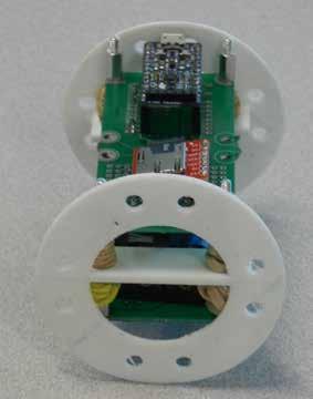
36 7. Building the Payload Rising Data Material Needed: 20 3/8 Hex Standoffs Two 3D printed Sleds Eight Rubber Bands Battery Board Payload Board 2. Place one 3/8 hex standoff through each of the outside holes on the battery board. Note that the battery side is facing up. Assembling the Payload 1. Using 12 of your 3/8 hex standoffs, create 4 11/8 standoffs by connecting 3 standoffs together as shown: 3. screw the 11/8 rails onto the threaded standoffs as shown. 7-1


37 4. wrap rubber bands around the rails as shown 6. Wrap another set of rubber bands around the rails as shown: 5. Place the 3D printed sleds over the rails as shown: 7. Place the protoboard as shown and secure it in place with the last four 3/8 hex standoffs See additional photos of the finished payload assembly at the end of the guide. 7-2


.")
38 8. Building the Rocket Rising Data Introduction The following are steps and methods to make building and modifying the Estes Big Daddy rocket easier. The modifications are neecessary to be able to fly the Rising Data payloads. There is a Youtube video available: SSU Rising Data that shows the construction of the engine mount (the hardest part of the build) and the modifications to the rocket. Do Not Attach The Rubber Shock Cord! Refer to the shock cord, parachute and recovery system section covered in the modifications segment and in the video. Note: you will not need the yellow and the orange tubes provided in the kit. Assembling the Engine Mount Material, Tools and Supplies Needed: Estes Big Daddy Rocket Kit and modification parts bag Needed in addition to the Rocket Kit: Pencil Drill with 9/64 bit Glue Hacksaw Hobby knife Masking tape Ruler Metric ruler Aluminum Scrubbing Pad Sandpaper Scissors Small Phillips screwdriver 2. Make a small incision with a sharp knife on the third mark (8.9 cm from the bottom). Remove the following from the small plastic bag in the rocket kit: B Engine mount tube: Light brown tube D Engine hook: Flat bent metal piece C Green engine block: Short green tube 1. Using a ruler measure from one end of the engine mount tube and make marks at 6 mm, 25 mm, 8.9 cm and 9.8 cm. 3. Place the end of the engine hook with the 90 bend into the incision you just made. Lay the rest of the engine hook against the tube. 8-1


 of the engine motor tube. 6.")


39 4. Use a piece of masking tape around the engine mount tube at the 25 mm mark to hold the engine hook in place. 7. Remove the centering rings out of the white cardboard and then remove the center pieces. 5. At the end of the tube where your 9.8 cm mark is, place a light ring of glue inside the tube. You should be able to see the engine hook sticking through the tube. 8. Place a ring of glue on the first mark (5mm) and the fourth mark (9.8 cm) of the engine motor tube. 6. Now take the green engine block tube and place it into the glue. Push it down until it contacts the protruding engine hook inside the engine mount tube. 9. Insert the brown tube through the centering rings lining them up with the marks on the tube. The notched ring goes on the bottom, and the un-notched ring goes on the top (the end with the green ring). Reinforce with some glue and let dry COMPLETELY. 8-2


40 2. Make a mark 13 mm from the top of the fin slots. You are now done building the engine mount. Preparing the Fins 3. Put a ring of glue on the inside of the body tube at the mark. 1. Punch out the fins from the balsa wood panels 2. Sand the fins as desired. 3. Take the rectangular fin inserts and test to see if they fit perpendicularly between the two centering rings of the engine mount. Do not glue! 4. Insert the entire engine mount into the bottom of the body tube. It is in the correct position when the top centering ring of the engine mount is aligned with the previously made mark (13 mm from the top of the fin slots). Mark the Main Tube 1. Draw a straight line from top to bottom of the main body tube between two of the fin slots. 8-3


41 5. NOTE: the engine hook must line up with the straight line made in Step One of this section. 3. Repeat for all four fins. Make sure that each fin is perpendicular to the rocket body. Do Not Install The Shock Cord at this time. Attaching the Fins Attaching the Launch Lug 1. Make a mark 11.4 cm from the bottom of the Rocket Body. Make sure that this mark is along the top to bottom lengthwise mark you made in a previous section. 1. Apply a thin layer of glue on the edge of the fin with the rectangular insert. 2. Insert the fin into a fin slot of the body tube. Glue both sides of the fin where it meets the body tube. 2. Apply a dab of glue on the launch lug, and place it on the lengthwise mark, going up from the mark from step one (11.4 cm from the bottom). Use a piece of masking tape to hold this until the glue dries. Let the glue dry


 to the other end of the black")

42 Modification as shown on YouTube The instructions below are steps selected from the video. It is strongly recommended to follow along: SSU Rising Data 1. The masking tape marks where to cut the base off the nose cone. 3b. Remove the disc. Then use a 9/64 bit and drill the nose cone on the mold line. Repeat on the opposite side of the cone. Then use the screws to secure the disc. 4. Tie the orange streamer to the shock cord 16 cm from the nose cone. 2. Insert the disc to one end of the black shock cord. Tie four or more overhand knots to secure it. 5. Attach the baffle (scrubbing pad) to the other end of the black shock cord at about 30 cm from the end. 3a. Place the white disc in the nose cone. Hold up the cone to the light to see the disc s edges and mark two lines on either side by the cone s mold line. Repeat on the opposite side of the cone. Final result of the modification assembly 8-5


43 Attaching the Shock Cord 1. Cut out the strip of paper (which will serve as the shock cord mount) with a pair of scissors. 4. When dried, place a dab of glue on the third section and fold the folded first and second sections on the third section. 2. Place a dab of glue on the second section of the piece of paper, and place one end of the black shock cord on the glue. 5. Next, place a dab of glue on the inside of the white tube, 8.9 cm from the top. 6. Place the paper shock cord mount onto the dab of glue on the inside of the rocket and let dry. Attaching the Parachute 3. Fold the first section on the second and let dry. 1. Cut the rubber shock cord in half. Attach one end to the cross bar on the 3D printed end of the payload sled. 8-6


44 2. Find the centers of the parachute s shroud lines. Tie them into a loop as a group. Tie the remaining end of the rubber shock cord to the loop you just formed. 3. Test the fit of the nose cone on the body. It should not be too tight or too loose, but just right! Congratulations, you have built a Big Daddy Rocket! Final Assembly 1. Finally, fold the parachute, and place it inside the body of the rocket. 2. Afterward, close the body cavity by placing the nose cone inside the top end of the rocket body. 8-7


45 Additional Payload Photos Rising Data Finished Payload Photos 9-1
46 Rising Data lbym.sonoma.edu/risingdata
Data. Table of Contents. Parts and Assembly Guide. 1. Rising Data Hardware Setup Arduino Integration SD Card Integration 3-1
 Rising Data Rising Data Table of Contents Chapters Parts and Assembly Guide 1. Rising Data Hardware Setup 2. Arduino Integration 3. SD Card Integration 4. 9DoF Integration 5. TMP-36 Integration 6. Battery
Teensy 3.5/3.6 Breakout (Revision A, Standard)
") Teensy 3.5/3.6 Breakout (Revision A, Standard) This is a breakout for the Teensy 3.5 and Teensy 3.6 development boards by PJRC. Included are all the pin headers you need to assemble it, a switch to select
Teensy 3.5/3.6 Breakout (Revision A, Standard) This is a breakout for the Teensy 3.5 and Teensy 3.6 development boards by PJRC. Included are all the pin headers you need to assemble it, a switch to select
Arduino Panel Meter Clock. By Russ Hughes
 Arduino Panel Meter Clock By Russ Hughes (russ@owt.com) OVERVIEW My father has been a lifelong Ham Radio Operator with a fondness for almost anything with a panel meter. After seeing the Trinket Powered
Adafruit BME280 Humidity + Barometric Pressure + Temperature Sensor Breakout
 Adafruit BME280 Humidity + Barometric Pressure + Temperature Sensor Breakout Created by lady ada Last updated on 2018-08-22 03:49:22 PM UTC Guide Contents Guide Contents Overview Pinouts Power Pins: SPI
OpenSprinkler v2.2u Build Instructions
 OpenSprinkler v2.2u Build Instructions (Note: all images below are 'clickable', in order for you to see the full-resolution details. ) Part 0: Parts Check Part 1: Soldering Part 2: Testing Part 3: Enclosure
3 pyro output datalogger altimeter with an ATmega 328 microcontroller Kit assembly instructions
 3 pyro output datalogger altimeter with an ATmega 328 microcontroller Kit assembly instructions Version date Author Comments 1.0 29/05/2013 Boris du Reau Initial version Rocket Type Micro-max Model Mid
Lab 0: Wire Wrapping Project: Counter Board
 Lab 0: Wire Wrapping Project: Counter Board September 3, 2008 In this experiment, you will build a simple counter circuit that can be plugged into your breadboard. It will provide a set of TTL output signals
OpenSprinkler v2.1u Build Instructions
 OpenSprinkler v2.1u Build Instructions (Note: all images below are 'clickable', in order for you to see the full-resolution details. ) Part 0: Parts Check Part 1: Soldering Part 2: Testing Part 3: Enclosure
PARTS LIST 1 x PC Board 36 x 5mm Red LED 36 x 12mm LED Standoff 36 x NPN Transistor 36 x 10kΩ Resistor OTHER PARTS YOU MAY NEED
 PARTS LIST 1 x PC Board 36 x 5mm Red LED 36 x 12mm LED Standoff 36 x NPN Transistor 36 x 150Ω Resistor 36 x 10kΩ Resistor 17 x Mini Toggle on-off 8 x Mini Toggle (on)-off-(on) 1 x 470Ω Resistor 1 x 47µF
Adafruit BME280 Humidity + Barometric Pressure + Temperature Sensor Breakout
 Adafruit BME280 Humidity + Barometric Pressure + Temperature Sensor Breakout Created by lady ada Last updated on 2017-01-11 09:01:04 PM UTC Guide Contents Guide Contents Overview Pinouts Power Pins: SPI
Parts List: Part # Tools List: Instructions:
 Parts List: Part # 1 pair of Dayton Audio B652s 300-652 1 Dayton Audio DTA-2 amplifier 300-385 1 MP3 module 320-350 1 7805 +5 VDC voltage regulator 7805 1 12 VDC 2A power supply 129-077 1 2.1 mm panel
Adafruit BME680. Created by lady ada. Last updated on :10:23 AM UTC
 Adafruit BME680 Created by lady ada Last updated on 2018-01-22 05:10:23 AM UTC Guide Contents Guide Contents Overview Pinouts Power Pins: SPI Logic pins: I2C Logic pins: Assembly Prepare the header strip:
Adafruit BMP280 Barometric Pressure + Temperature Sensor Breakout
 Adafruit BMP280 Barometric Pressure + Temperature Sensor Breakout Created by lady ada Last updated on 2017-12-09 06:21:37 PM UTC Guide Contents Guide Contents Overview Pinouts Power Pins: SPI Logic pins:
RC Tractor Guy Controller V2.1 Assembly Guide
 RC Tractor Guy Controller V. Assembly Guide Features 0 Push button inputs Dual axis thumb sticks with built-in push button Rotary encoders with built-in push button MCU Socket to suit Meduino Mega 560
The Radio Control Temperature Logger (RCTL) Manual For hardware version 1.0 Manual version 1.0b
 Manual For hardware version 1.0 Manual version 1.0b") The Radio Control Temperature Logger (RCTL) Manual For hardware version 1.0 Manual version 1.0b All materials owned by Dan Gebhardt Introduction This device records the temperature of a model engine during
The Radio Control Temperature Logger (RCTL) Manual For hardware version 1.0 Manual version 1.0b All materials owned by Dan Gebhardt Introduction This device records the temperature of a model engine during
BalloonSat Sensor Array
 BalloonSat Sensor Array The PICAXE-08M2 in the BalloonSat flight computer is a digital device. Being digital, it functions best with a series of on and off voltages and does not interact very well with
When you are ready to build your computer you will have the following materials to work with.
 Copyright 2009 BOSMA Enterprises Chapter 3 Putting the Computer Together When you are ready to build your computer you will have the following materials to work with. 1. One motherboard. 2. One ribbon
4.1 Parts and Components... IV Assembly Tips... IV Assembly Precautions... IV Required Tools, Equipment and Materials..
 IV PERSONALITY MODULE ASSEMBLY 4.1 Parts and Components............ IV-1 4.2 Assembly Tips............... IV-1 4.3 Assembly Precautions............ IV-1 4.4 Required Tools, Equipment and Materials.. IV-1
Wii Nunchuk Transceiver. Wiring Diagrams
 Wii Nunchuk Transceiver Wiring Diagrams Wii Nunchuk Controller Wiring SCL SCL SDA +3v3 +3v3 Det SDA To Nunchuk Controller Top View Bottom View Bottom View 2.4GHz Wireless Transceiver CMD RXD TXD VCC 220Ω
Post Tenebras Lab. Written By: Post Tenebras Lab
 Post Tenebras Lab PTL-ino is an Arduino comptaible board, made entirely out of through-hole components. It is a perfect project to learn how to solder and start getting into the world of micro controllers.
keyestudio Keyestudio MEGA 2560 R3 Board
 Keyestudio MEGA 2560 R3 Board Introduction: Keyestudio Mega 2560 R3 is a microcontroller board based on the ATMEGA2560-16AU, fully compatible with ARDUINO MEGA 2560 REV3. It has 54 digital input/output
Warranty Disclaimer. Limitation of Liability
 Warranty Disclaimer Purchaser acknowledges that Top Cat Engineering L.L.C.has agreed to provide this kit for evaluation purposes only. Purchaser further acknowledges that Top Cat Engineering has no obligations
Adafruit USB Power Gauge Mini-Kit
 Adafruit USB Power Gauge Mini-Kit Created by Bill Earl Last updated on 2017-07-14 11:55:04 PM UTC Guide Contents Guide Contents Overview Assembly Basic Assembly Solder the female connector. Solder the
ROTOPOD PERISCOPE LIGHTING KIT
 ROTOPOD PERISCOPE LIGHTING KIT (for ULTIMATE Periscopes) 14-MAR-2013_rev 2.0 I designed the Periscope Lighting Kit to be as flexible as possible. Every LED is individually controllable. I have provided
Pacific Antenna Two Tone Generator
 Pacific Antenna Two Tone Generator Description Our Two Tone Generator kit provides two non-harmonic, sine wave signals for testing audio circuits Outputs of approximately 700Hz and 1900Hz and the combination
Constructing a Low-Cost Mobile Eye Tracker
 ==== Constructing a Low-Cost Mobile Eye Tracker ==== Section 1: Introduction This is a detailed set of instructions on how to build a low-cost mobile eye-tracking system from off-the-shelf components.
Figure 1. The completed programming kit List of Parts
 Many NearSys kits are programmed through a three pin header soldered to the PCB. Since a three pin receptacle is not a common termination for a serial cable, this kit contains the parts to make one. In
A Backlighted LCD for your K1
 A Backlighted LCD for your K1 (K1BKLTKIT) Tom Hammond - NØSS, July 27, 2006 Rev C Thanks to Wayne Burdick, N6KR for suggesting this implementation of backlighting the K1 display. APPLICABILITY This modification
The GENIE Light Kit is ideal for introducing simple lighting projects, such as an electronic die, a wearable badge or a night-time warning system.
 Introduction 1 Welcome to the GENIE microcontroller system! The GENIE Light Kit is ideal for introducing simple lighting projects, such as an electronic die, a wearable badge or a night-time warning system.
An open-source hardware+software project. For design files and additional documentation, please visit:
 An open-source hardware+software project. For design files and additional documentation, please visit: http://www.evilmadscientist.com/go/diavolino Support: http://www.evilmadscientist.com/forum/ Distributed
1/Build a Mintronics: MintDuino
 1/Build a Mintronics: The is perfect for anyone interested in learning (or teaching) the fundamentals of how micro controllers work. It will have you building your own micro controller from scratch on
Onwards and Upwards, Your near space guide Overview of the NearSys Two Sensor Temperature Array Figure 1. A complete Two Sensor Temperature Array
 The NearSys Two Sensor Temperature Array is a kit that permits a BalloonSat to measure two separate temperatures. When plugged into a flight computer like the BalloonSat Mini, the flight computer provides
Quicksilver 606 TR-606 CPU Upgrade
 Quicksilver 606 TR-606 CPU Upgrade D650C 128 Installation Guide Social Entropy Electronic Music Instruments TABLE OF CONTENTS WARNINGS... 1 OVERVIEW... 2 WHAT'S IN THE BOX... 3 OPENING THE TR-606 CASE...
How to Assemble a Desktop PC
 How to Assemble a Desktop PC By Taylor Koch iii Table of Contents Introduction to Building a Desktop PC... 1 Preparation and Precautions... 3 PC Parts... 3 Basic Tools... 3 Safety Precautions... 3 Installing
Bill of Materials: Turn Off the Lights Reminder PART NO
 Turn Off the Lights Reminder PART NO. 2209650 Have you ever woke up early in the morning to find out that the kids (or adults) in your home forgot to turn off the lights? I've had that happen a number
GPS Series. Build a GPS Smart Logger. By Michael Simpson. As seen in November 2008 of Servo Magazine Pick up an issue at
 GPS Series By Michael Simpson Build a GPS Smart Logger As seen in November 2008 of Servo Magazine Pick up an issue at www.servomagazine.com I recently did a GPS series covering various GPS modules and
Shack Clock kit. U3S Rev 2 PCB 1. Introduction
 Shack Clock kit U3S Rev 2 PCB 1. Introduction Thank you for purchasing the QRP Labs Shack Clock kit. This clock uses the Ultimate3S QRSS/WSPR kit hardware, but a different firmware version. It can be used
HP Pavilion dv7-6c90us Cooling fan Replacement
 HP Pavilion dv7-6c90us Cooling fan Replacement This guide will walk you through the process of replacing the cooling fan in an HP Pavilion dv7 laptop. Written By: Angelina Clayton ifixit CC BY-NC-SA www.ifixit.com
Part 2: Building the Controller Board
 v3.01, June 2018 1 Part 2: Building the Controller Board Congratulations for making it this far! The controller board uses smaller components than the wing boards, which believe it or not, means that everything
Building the VMW Time Circuitry Meter by Vincent M. Weaver 6 May 2014
 Building the VMW Time Circuitry Meter http://www.deater.net/weave/vmwprod/hardware/time_circuit/ by Vincent M. Weaver 6 May 2014 1 Introduction This is a work in progress. I will update it as I complete
Universal Keying Adapter 3+
 Universal Keying Adapter 3+ The Universal Keying Adapter Version 3+ kit will allow you to key nearly any transmitter or transceiver with a straight key, electronic keyer, computer serial or parallel port
Last Updated May 11, Electronics and Robotics LLC. ootbrobotics.com
 µpad Proto Base Assembly Guide Last Updated May 11, 2015 Table of Contents Required Tools... 5 Recommended Tools... 5 Assembly Procedure... 6 Step 1: Break Pin Headers to Size... 6 Table 1: Header Cut
AT42QT1010 Capacitive Touch Breakout Hookup Guide
 Page 1 of 7 AT42QT1010 Capacitive Touch Breakout Hookup Guide Introduction If you need to add user input without using a button, then a capacitive touch interface might be the answer. The AT42QT1010 Capacitive
Phi -1 shield Documentation. Table of content
 Phi -1 shield Documentation Last reviewed on 01/03/11 John Liu Table of content 1. Introduction: 2 2. List of functions: 2 3. List of possible projects: 2 4. Parts list: 3 5. Shield pin usage: 3 6. List
Assembly of the TACOS WAT-910BD Housing v2
 1) Circuit Diagram 2) Assembly of PCB a)tools Required. Only simple hand tools are necessary to complete the assembly of the PCB. - Soldering Iron and solder - Needle nose pliers - Wire clippers/trimmers
The Basic Counter. Hobby Electronics Soldering Kit. Instruction Guide
 The Basic Counter Hobby Electronics Soldering Kit Instruction Guide TM For the best outcome, follow each step in order. We recommend reading this guide entirely before you get started. Tools required:
Figure 1. A complete Temperature Sensor
 The NearSys Temperature Sensor is a kit that permits a BalloonSat to measure the temperature of the air, interior, or object the sensor itself is placed in contact with. When plugged into a flight computer
Mailbox Notification Service. Created by Adam Kohring
 Mailbox Notification Service Created by Adam Kohring Last updated on 2015-06-24 10:20:07 PM EDT Guide Contents Guide Contents Overview Parts List Adafruit Products Additional Products Print the Circuit
EE 354 August 1, 2017 Assembly of the AT89C51CC03 board
 EE 354 August 1, 2017 Assembly of the AT89C51CC03 board The AT89C51CC03 board comes as a kit which you must put together. The kit has the following parts: No. ID Description 1 1.5" x 3.25" printed circuit
VG-305A AC Traffic Light Controller Kit
 Galak Electronics Electronic kits and components Website: GalakElectronics.com Email: sales@galakelectronics.com Phone: (302) 832-1978 VG-305A AC Traffic Light Controller Kit Thank you for your purchase
Button Code Kit. Assembly Instructions and User Guide. Single Button Code Entry System
 Button Code Kit Single Button Code Entry System Assembly Instructions and User Guide Rev 1.0 December 2009 www.alan-parekh.com Copyright 2009 Alan Electronic Projects Inc. 1. Introduction... 4 1.1 Concept
Advanced Strobe 1.0 Kit
 Kit Instruction Manual Eastern Voltage Research, LLC December 2013, Rev 1 1 http://www.easternvoltageresearch.com Kit Introduction to the Kit Thank you for purchasing the Kit. If you are looking for a
Revised: Page 1
 Brought To You By And Designed By: Revised: 2017-05-07 Page 1 Features Of The Universal PSU Kit: Fits all standard Apple II and /// Power Supply Enclosures. (all parts included, user supplies household
Building the FlipChip Tester
 Building the FlipChip Tester 1. Assembly of the Core Board You will need a fine low-wattage soldering iron and a Voltmeter. Take your time to solder the components on the Core Board. Better to spend a
Single cable kit for the FCB1010
 Single cable kit for the FCB1010 1. What is it? With this kit, you can turn your FCB1010 into a phantom powered floorboard, which can do 2-way MIDI communication over one single cable. After installing
Adafruit Terminal Block Breakout FeatherWing
 Adafruit Terminal Block Breakout FeatherWing Created by lady ada Last updated on 2017-01-04 04:53:26 AM UTC Guide Contents Guide Contents Overview Pinouts Assembly Downloads Datasheets & Files Schematic
EQ573 Assembly guide. EQ573 Assembly guide Main board 1. Diodes. 2. Resistors (1) 3. Test pins. 4. Ceramic capacitors.
 3. Test pins. 4. Ceramic capacitors.") EQ573 Assembly guide Safety warning The kits are main powered and use potentially lethal voltages. Under no circumstance should someone undertake the realisation of a kit unless he has full knowledge about
EQ573 Assembly guide Safety warning The kits are main powered and use potentially lethal voltages. Under no circumstance should someone undertake the realisation of a kit unless he has full knowledge about
MACRO MODCHIP FOR XBOX360 CG2 INSTALLATION INSTRUCTIONS
 MACRO MODCHIP FOR XBOX360 CG2 INSTALLATION INSTRUCTIONS List of tools and materials needed: Modchip, flexible LED add-on board, 6 tac switches Microsoft wireless CG2 controller Soldering iron and thin
BuffaloLabs WiFi Lantern Assembly guide version 1
 BuffaloLabs WiFi Lantern Assembly guide version 1 Needed equipment: Solder iron Solder wire Cutter Wire stripper (optional) Hot glue gun Overview of the components (not including USB cable and box panels)
Hardware Overview and Features
 Hardware Overview and Features Don t snap apart your LilyPad ProtoSnap Plus until you're ready to use the pieces in a project. If you leave the pieces attached to the board, you'll be able to prototype
Rover 5. Explorer kit
 Rover 5 Explorer kit The explorer kit provides the perfect interface between your Rover 5 chassis and your micro-controller with all the hardware you need so you can start programming right away. PCB Features:
Propeller Project Board USB (#32810)
") Web Site: www.parallax.com Forums: forums.parallax.com Sales: sales@parallax.com Technical: support@parallax.com Office: (916) 624-8333 Fax: (916) 624-8003 Sales: (888) 512-1024 Tech Support: (888) 997-8267
Web Site: www.parallax.com Forums: forums.parallax.com Sales: sales@parallax.com Technical: support@parallax.com Office: (916) 624-8333 Fax: (916) 624-8003 Sales: (888) 512-1024 Tech Support: (888) 997-8267
Connecting igaging DigiMAG Scales to the Caliper2PC Interface A step by step Guide
 What is an igaging DigiMAG Scale? The igaging DigiMAG are digital linear scales that are easily connectable to the Caliper2PC interface. They consist of two parts, the encoder and the readout unit. The
Prototyping & Engineering Electronics Kits Basic Kit Guide
 Prototyping & Engineering Electronics Kits Basic Kit Guide odysseyboard.com Please refer to www.odysseyboard.com for a PDF updated version of this guide. Guide version 1.0, February, 2018. Copyright Odyssey
Introduction to Arduino (programming, wiring, and more!)
") Introduction to Arduino (programming, wiring, and more!) James Flaten, MN Space Grant Consortium with Ben Geadelmann, Austin Langford, et al. University of MN Twin Cities Aerospace Engineering and Mechanics
Introduction to Arduino (programming, wiring, and more!) James Flaten, MN Space Grant Consortium with Ben Geadelmann, Austin Langford, et al. University of MN Twin Cities Aerospace Engineering and Mechanics
Construction Construction Instructions
 Semi-Virtual Diskette SVD Construction Construction Instructions PCB version 2.0 September 2004 Eric J. Rothfus Table of Contents Table of Contents... i Parts List...1 Construction Overview...5 PCB Construction...
Physics 120/220 Lab Equipment, Hints & Tips
 Physics 120/220 Lab Equipment, Hints & Tips Solderless Breadboard... 2 Power supply... 4 Multimeters... 5 Function generator... 5 Oscilloscope... 6 10X probe... 7 Resistor color code... 7 Components...
Arduino Uno. Arduino Uno R3 Front. Arduino Uno R2 Front
 Arduino Uno Arduino Uno R3 Front Arduino Uno R2 Front Arduino Uno SMD Arduino Uno R3 Back Arduino Uno Front Arduino Uno Back Overview The Arduino Uno is a microcontroller board based on the ATmega328 (datasheet).
AT42QT101X Capacitive Touch Breakout Hookup Guide
 Page 1 of 10 AT42QT101X Capacitive Touch Breakout Hookup Guide Introduction If you need to add user input without using a button, then a capacitive touch interface might be the answer. The AT42QT1010 and
Reflowing Xbox 360 Motherboard
 Reflowing Xbox 360 Motherboard Reflow the solder on your Xbox 360's motherboard. Written By: Andrew Bookholt ifixit CC BY-NC-SA www.ifixit.com Page 1 of 31 INTRODUCTION Use this guide to reflow the solder
Assembling the Printed Circuit Board for the EDE1200 Robot
 This board receives instructions from either a CBL2, a LabPro or (with an adapter cable) an original CBL. The board has two 595 shift registers (each providing 8 bits of on-board memory) and two EDE1200
Nov. 07, 2013 p. 5 - changed the B axis unit value to from Changed by Randy per Frank s request.
 Correction notes Nov. 07, 2013 p. 5 - changed the B axis unit value to 45.1389 from 40.0000. Changed by Randy per Frank s request. Jan. 22, 2018 p. 5 - changed the B axis unit value and corresponding picture
Metro Minimalist Clock
 Metro Minimalist Clock Created by John Park Last updated on 2018-08-22 04:01:22 PM UTC Guide Contents Guide Contents Overview For this build you'll need: Clock Circuit Code the Clock Display the Clock
Insert the male, 90 angled, 2x10 connectors into the corresponding 2x10 sockets and put them in place, flat under the PCB. Solder.
 MC624 Assembly guide Safety warning The kits are main powered and use potentially lethal voltages. Under no circumstance should someone undertake the realisation of a kit unless he has full knowledge about
Flight Data Recorder Hardware Version 1.0
 Flight Data Recorder Hardware Version 1.0 By R. G. Sparber Scope The Flight Data Recorder (FDR) hardware is described here. The software is described in a separate document. The reader can etch their own
Experimental Procedure
 1 of 14 9/10/2018, 11:38 AM https://www.sciencebuddies.org/science-fair-projects/project-ideas/robotics_p028/robotics/obstacle-avoiding-robot (http://www.sciencebuddies.org/science-fair-projects /project-ideas/robotics_p028/robotics/obstacle-avoiding-robot)
Adafruit 1-Wire Thermocouple Amplifier - MAX31850K
 Adafruit 1-Wire Thermocouple Amplifier - MAX31850K Created by lady ada Last updated on 2015-04-09 03:45:15 PM EDT Guide Contents Guide Contents Overview Pinouts Power Pins Address Pins Data Pin Themocouple
INSTRUCTIONS FOR THE INSTALLATION OF THE INFINITY "L" DISPLAY HOOD (INTO PREVIOUSLY INSTALLED INFINITY "L" SYSTEMS)
") Doc. 6001025 Rev B INSTRUCTIONS FOR THE INSTALLATION OF THE INFINITY "L" DISPLAY HOOD (INTO PREVIOUSLY INSTALLED INFINITY "L" SYSTEMS) Rev. B Doc. 6001025 Page 1 of 13 IMPORTANT NOTICE This document covers
Doc. 6001025 Rev B INSTRUCTIONS FOR THE INSTALLATION OF THE INFINITY "L" DISPLAY HOOD (INTO PREVIOUSLY INSTALLED INFINITY "L" SYSTEMS) Rev. B Doc. 6001025 Page 1 of 13 IMPORTANT NOTICE This document covers
K8099 NIXIE CLOCK. * optional enclosure TKOK19 (black) - TKOK17 (white) ** optional plexiglass enlcosure B8099 ILLUSTRATED ASSEMBLY MANUAL
 - TKOK17 (white) ** optional plexiglass enlcosure B8099 ILLUSTRATED ASSEMBLY MANUAL") Total solder points: 230 + 74 Difficulty level: beginner 1 2 3 4 5 advanced NIXIE CLOCK K8099 ** * A unique combination of both vintage and modern electronics ILLUSTRATED ASSEMBLY MANUAL H8099IP-1 * optional
Total solder points: 230 + 74 Difficulty level: beginner 1 2 3 4 5 advanced NIXIE CLOCK K8099 ** * A unique combination of both vintage and modern electronics ILLUSTRATED ASSEMBLY MANUAL H8099IP-1 * optional
Uzebox Kit Assembly Guide
 Uzebox Kit Assembly Guide V1.3 Page 1 of 18 Revision History Version Date Author Description 1.0 01-Nov-2012 A.Bourque Initial release 1.1 6-Nov-2012 A.Bourque Minor corrections 1.2 28-Jan-2014 A.Bourque
BMC24. MIDI TO GATE CONVERTER DOCUMENTATION. This documentation is for use with the "Euro Style" bottom board.
 BMC24. MIDI TO GATE CONVERTER DOCUMENTATION. This documentation is for use with the "Euro Style" bottom board. A. USING THE MIDI TO GATE CONVERTER B. PARTS LIST C. BUILDING INSTRUCTIONS D. SCHEMATICS Revision.
ARDUINO MEGA 2560 REV3 Code: A000067
 ARDUINO MEGA 2560 REV3 Code: A000067 The MEGA 2560 is designed for more complex projects. With 54 digital I/O pins, 16 analog inputs and a larger space for your sketch it is the recommended board for 3D
Adafruit 1-Wire Thermocouple Amplifier - MAX31850K
 Adafruit 1-Wire Thermocouple Amplifier - MAX31850K Created by lady ada Last updated on 2018-08-22 03:40:09 PM UTC Guide Contents Guide Contents Overview Pinouts Power Pins Address Pins Data Pin Themocouple
Alesis MMT8 16x Memory Expansion Modification (Black model MMT8 s) Equipment. Components required. Other bits:
 Equipment. Components required. Other bits:") Alesis MMT8 16x Memory Expansion Modification (Black model MMT8 s) by Graham Meredith, 006 Revised 15 th January 009 gmeredith1@yahoo.com.au This modification expands the memory of the Alesis MMT8 to 16x
Alesis MMT8 16x Memory Expansion Modification (Black model MMT8 s) by Graham Meredith, 006 Revised 15 th January 009 gmeredith1@yahoo.com.au This modification expands the memory of the Alesis MMT8 to 16x
Onwards and Upwards, Your near space guide. Figure 1. CheapBot Line Follower
 The CheapBot Line Follower is a plug-in single-board sensor for almost any programmable robot brain. With it, a robot can detect the presence of a black or white zone beneath its two sensors. In its simplest
BS2p40tm OEM Module. Surface mount/through hole kit By Robert L. Doerr. Manual Revision.5
 BS2p40tm OEM Module Surface mount/through hole kit 2006 By Robert L. Doerr Manual Revision.5 NOTE: The BASIC Stamp and the BS2p40 and Interpreter chip are trademarks of Parallax. This partial kit allows
Adafruit VL53L0X Time of Flight Micro-LIDAR Distance Sensor Breakout
 Adafruit VL53L0X Time of Flight Micro-LIDAR Distance Sensor Breakout Created by lady ada Last updated on 2016-12-05 06:40:45 PM UTC Guide Contents Guide Contents Overview Sensing Capablities Pinouts Power
CP5176 Assembly guide. Soldering. CP5176 Assembly guide Main PCB PCB split. Document revision 2.1 Last modification : 12/11/17
 CP5176 Assembly guide Safety warning The kits are main powered and use potentially lethal voltages. Under no circumstance should someone undertake the realisation of a kit unless he has full knowledge
ATTiny84/85 AVR adapter kit building and usage instructions
 ATTiny84/85 AVR adapter kit building and usage instructions Version date Author Comments 1.0 25/06/2013 Boris du Reau Initial version 1.1 30/09/2013 Boris du Reau Updated document 1 Goal... 2 2 Kit content...
Bill of Materials: Programming Interface for AVR PART NO
 Programming Interface for AVR PART NO. 2174664 "Programmers" for the AVR family of microcontrollers actually terminate in a 6-pin header socket, with no convenient means to directly connect to the chip
Casio CZ. Non volatile memory modification Installation instructions version copyright 2013 Artefacts
 Casio CZ Non volatile memory modification Installation instructions version 2.0 2017 www.artefacts.nl copyright 2013 Artefacts Introduction The Casio CZ-101 and CZ-1000 do not have a separate backup battery
the TS-520 Noise Blanker board to and making wiring changes to your SB-303 receiver!!!!
 The Kenwood TS-520 s Noise Blanker board, ID# X54-1080-10, can be installed in a Heathkit SB-303 receiver quite easily. The Noise Blanker board operates directly off of the SB-303 s 15VDC supply. Therefore,
3 Indexer Installation For PRSalpha Tools
 888-680-4466 ShopBotTools.com 3 Indexer Installation For PRSalpha Tools Copyright 2016 ShopBot Tools, Inc. page 1 Copyright 2016 ShopBot Tools, Inc. page 2 Table of Contents General Safety and Precautions...5
Dwarf Boards. DB057 : 40-pin controller board
 Dwarf Boards DB057 : 40-pin controller board PICmicro, In-Circuit Serial Programming and ICSP are registered trademarks of Microchip Technology Inc. DB057 for USB PIC DB057 for non-usb PIC Introduction
Construction manual. (Almost Ready To Control) Stand , V1.05
 Stand , V1.05") V.3 ARTC Construction manual V.3 ARTC (Almost Ready To Control) Stand 5.08.206, V.05 Qube Solutions UG (limited liability) Arbachtalstr. 6, 72800 Eningen, GERMANY http://www.qube-solutions.de/ http://
V.3 ARTC Construction manual V.3 ARTC (Almost Ready To Control) Stand 5.08.206, V.05 Qube Solutions UG (limited liability) Arbachtalstr. 6, 72800 Eningen, GERMANY http://www.qube-solutions.de/ http://
Educato. Assembly Instructions
 Product Description The Educato is an Arduino compatible board that has about the functionality of the Arduino Uno. It also has the ability, however, to plug into a solderless breadboard and to have all
IQ32 Upgrade Kit Assembly Instructions
 IQ32 Upgrade Kit Assembly Instructions Jim Veatch WA2EUJ September 17, 2018 TABLE OF CONTENTS 1. INTRODUCTION... 3 2. IQ-32 UPGRADE KIT INVENTORY... 4 3. PREPARING THE RS-HFIQ AND SIDE PANELS... 6 4. CONNECTING
edrive RAM Battery Alternate Replacement Procedure
 edrive RAM Battery Summary This technical note describes the process for replacing the TINI RAM battery with a higher capacity battery. With the edrive turned on, the external battery can be changed without
Elecraft K3 KPA3 Power Connector Replacement Revision B, June 30, 2017 Copyright 2017, Elecraft, Inc. All Rights Reserved
 Introduction Elecraft K3 KPA3 Power Connector Replacement Revision B, June 30, 2017 Copyright 2017, Elecraft, Inc. All Rights Reserved The connectors furnishing high current to the KPA3 module have failed
[Note: Power adapter is not included in the kits. Users need to prepare a 9 12 V ( >300mA capacity ) DC power supply]
![[Note: Power adapter is not included in the kits. Users need to prepare a 9 12 V ( >300mA capacity ) DC power supply]](/thumbs/76/74094055.jpg "[Note: Power adapter is not included in the kits. Users need to prepare a 9 12 V ( >300mA capacity ) DC power supply]") 062 LCD Oscilloscope Assembly Notes Applicable Models: 06203KP, 06204KP DN062-18v02 Important Notes 1. Some components shown in the schematic and PCB layout are for options or adjustments. They do not
062 LCD Oscilloscope Assembly Notes Applicable Models: 06203KP, 06204KP DN062-18v02 Important Notes 1. Some components shown in the schematic and PCB layout are for options or adjustments. They do not