Solar Analysis System Quick Start Instructions
|
|
|
- Gervase Allison
- 5 years ago
- Views:
Transcription


1 RaySphere and RaySphere 1700 Description Solar Analysis System Quick Start Instructions RaySphere is a calibrated high-performance measurement device. It is designed for testing the spectral distribution of all types of Solar Simulators and for validating the simulator for the spectral match test in accordance with the international standard IEC : Solar Simulator Performance Requirements. The RaySphere series of products consists of RaySphere and RaySphere They provide the following features: Intuitive graphical interface Graphical and table display of classification results by wavelength bin Output of actual spectra in mw/cm 2 /nm Output of actual measurement and triggering timing with +/-44 µs resolution Printable classification report RAYSPHERE
2 RaySphere contains one QE65000 spectrometer, while RaySphere 1700 contains two spectrometers (QE65000 and NIRQuest512), a trigger unit to control the measurement procedure and a hub. The trigger sources can be a flash from the solar simulator, an electrical trigger pulse (high level with +5 V or +24 V), or a measurement can be generated manually at any time. RaySphere software allows full control during the testing and generates a test report with the classification of the simulator. This document provides you with information for testing a solar simulator with your RaySphere or RaySphere 1700 product. Detailed information for the RaySphere and RaySphere 1700 are provided in the RaySphere Solar Analysis System Installation and Operation Manual. Parts Included The RaySphere package consists of the following items: Pelican case: The transport box for the complete RaySphere System RaySphere main body Power Supply Four Power Cables, one each for USA, Europe, UK, and Australia Power Supply Connection Cable SubD-type, 3-meter length USB cable (USB-CBL-1): Connects RaySphere to a computer s USB port (3-meter length) RaySphere CD: Contains RaySphere software and calibration files and manuals Software and Technical Resources CD: Contains software, operating instructions, and product information for all Ocean Optics software, spectrometers, and spectroscopic accessories. You need Adobe Acrobat Reader version 6.0 or higher to view these files (version 7.0 is included on the CD). Documentation is also available on our website at Passwords: For any Ocean Optics software that you have purchased. Passwords are located on the back of the Software and Technical Resources CD jacket. Calibration documents Important Safety Notices 1. Read the instructions first to avoid any damages. 2. Store your RaySphere system at above -10 C and below 50 C to avoid any damages. 3. This is a calibrated measurement device. Handle the system with care. The calibration precision may be lost if any dust or other pollutant enters the integrating sphere. When the system is not in use, store it with a dust protector. When removing the dust protector, be sure to keep pollutants from entering the integrating sphere aperture. 4. Recalibration is recommended after one year of use, or sooner if the measurements do not seem to be accurate. More frequent recalibration may be needed of the RaySphere has suffered any heavy shocks or is being used in a dusty environment. 5. The RaySphere is heavy. Take care to keep it from falling. 2 RAYSPHERE
3 6. If the seal on the screws is broken, then the calibration is no longer valid. 7. Do not cover vents. 8. Do not cover the holes at the top of the RaySphere s main body. RaySphere and RaySphere 1700 Instructions 9. To ship the RaySphere, pack it in the Pelican case, which is optimized for transport. Hand carrying the RaySphere is recommended for all traveling. 10. Contact your Ocean Optics regional headquarters for questions about RaySphere. 11. Be sure to follow all safety instructions for your solar simulator. Installing Software Caution Install the software BEFORE connecting the spectrometer to your PC. The SpectraSuite software installs the drivers required for spectrometer installation. If you do not install SpectraSuite first, the system will not properly recognize the spectrometer. RaySphere includes special software for operating your RaySphere system. This software is located on the RaySphere CD. The installation instructions are included below. In addition, if you have purchased and are using SpectraSuite, follow the instructions in the SpectraSuite Spectrometer Operating Software Installation and Operation Manual for software installation instructions. Caution Do not run SpectraSuite and RaySphere software at the same time on the computer. Procedure To install RaySphere software from the RaySphere CD, 1. Close all other applications running on the computer. 2. Load the RaySphere CD. The CD contains the calibration data, fundamental settings and the software for operating the RaySphere on a 32-bit or 64-bit computer. 3. Select the Setup CD folder. 4. Select the installation file for either a 32- or 64-bit system. The setup process begins and the following screen appears: RAYSPHERE


4 5. Click the Install button. Then follow the prompts in the installation wizard. Note If the following screen appears during the installation, select Repair: 6. Click Close when the installation is completed. It is not necessary to restart your computer. 4 RAYSPHERE
5 Assembling RaySphere RaySphere and RaySphere 1700 Instructions Follow the steps below to set up your RaySphere for use. It is recommended to perform 3 spectrum recordings (and to excite 3 flashes) within 5 minutes and to use the data from the last flash for the validation and certificate. Procedure 1. Connect the power cable to the power supply. 2. Connect the RaySphere unit to the power supply with the SubD cable. 3. Switch on the power supply. 4. Connect the RaySphere to your computer using a USB cable. Caution Be sure to switch on the power supply before connecting the RaySphere to your computer. Your RaySphere is now ready to use after 20 minutes of warm-up time. Using RaySphere with a Flash Solar Simulator Procedure 1. Place the assembled RaySphere main body close to the test plane so that its aperture is centered in the middle of the test plane. 2. If you are using an electrical trigger signal, select the correct input level for trigger signal at the power supply, and apply the signal cable to the BNC-connector on the power supply. 3. Make sure that the RaySphere software has been installed on the computer you intend to use. 4. Switch on the RaySphere power supply. Caution Always be sure to switch on the power supply before connecting the RaySphere to your computer. 5. Connect RaySphere via USB cable with your computer. 6. Start the RaySphere software. 7. Press Load Config ( ) on the System tab to load your solar simulator configuration file. 8. Wait 20 minutes for RaySphere to reach the thermal equilibrium. Measure the dark spectrum again. RAYSPHERE
6 9. Press QE65000 ( ) and NIR ( ) in the Spectrometer tab. Use the opening dialog box for recording a dark spectrum measurement. 10. Press Start ( ) in the software interface. 11. Generate 5 single flashes with maximum speed of 1 Hz within 3 minutes. RaySphere records the data. 12. Select Save All ( ) in the RaySphere software. Include the serial number of the flasher in the name of the file. The test report is generated automatically. Using RaySphere with a Continuous Solar Simulator Procedure 1. Switch on the solar simulator. 3. Make sure that the RaySphere software has been installed on the computer you intend to use. 4. Switch on the RaySphere power supply. Caution Always be sure to switch on the power supply before connecting RaySphere to your computer. 5. Connect RaySphere via USB cable with your computer. 6. Start the RaySphere software. 7. Wait 20 minutes for RaySphere to reach thermal equilibrium. 8. Press Load Config ( ) on the System tab to load your solar simulator configuration file. 9. Cover the RaySphere aperture (you can use the dust protector). Take a dark spectrum measurement by pressing QE65000 ( ) and NIR ( ) in the Spectrometer tab. 10. Uncover the RaySphere aperture. 11. Place the assembled RaySphere main body close to the test plane so that its aperture is centered in the middle of the test plane. 12. Press Sample ( ) in the RaySphere software interface 5 times each second. The RaySphere records the data. 13. Select Save All ( ) in the RaySphere software. Include the serial number of the flasher in the name of the file. The test report is generated automatically. 6 RAYSPHERE
7 Validating the Test Results Check the following to be sure that you are collecting valid data: The RaySphere was allowed to warm up for at least 20 minutes before starting the test. No error or warning messages were received when the calibration file was loaded. The spectra recording was during the stable flash time phase. Check that all marks for Start and End of Recording in the Photocurrent graph are at a stable flash time. Specifications Specification Value Electrical: Input voltages Input frequency Power Overvoltage protection Fuse Trigger connection VAC Hz 75 W % of main output M1.6 A BNC connector Connector: SMA 905 Optical: Optical input power Wavelength range*: RaySphere RaySphere W to 2000 W nm 300 nm 1700 nm Optical Trigger: Trigger delay ms Time resolution 0.87 µs Jitter 150 ns Internal time resolution 2.54 µs Electrical Trigger: Electrical trigger type High level Minimum high time Connector High level 5 V or 24 V (selected at the power supply. Galvanically isolated input.) 100 ns BNC RAYSPHERE
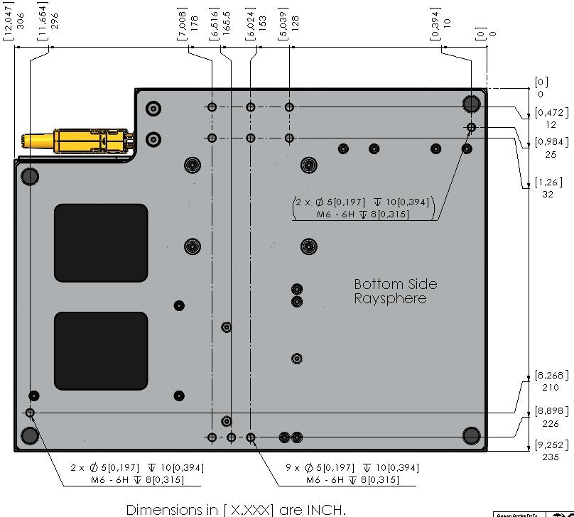
8 Specification Value Delays and Timing: Fixed internal delay*: NIRQuest QE65000 Internal delay External delay 1030 µs 768 µs Selectable in 500 ns increments. Maximum steps ms General: Operating temperature 15 C 33 C Storage temperature -10 C 45 C Dimensions (l x w x h) Weight RaySphere RaySphere 1700 USB Cable 30.7 cm x 23.5 cm x 6.6 cm 4.2 kg (main body) 5.7 kg (main body) No longer than 5 m *See the specific spectrometer manuals for more details Mounting Options for RaySphere Main Body and Mechnical Diagram The technical drawing shows the back side of the RaySphere main body. The system can be mounted at the indicated M6 rods only. WARNINGS Do not bend the system for tight mounting! Mounting on uneven surfaces may bend the RaySphere system. This may cause increased measurement uncertainties. 8 RAYSPHERE
9 RAYSPHERE
10 10 RAYSPHERE
STS Spectrometer Getting Started
 STS Spectrometer Getting Started STS is a family of compact, low-cost spectrometers ideal for embedding into OEM devices. STS provides remarkable performance for a spectrometer of its size (just 40 mm
Absolute Irradiance Installation and Operation Manual
 Absolute Irradiance Installation and Operation Manual For Products: JAZ-IRRAD Document: JAZ-A-IRRAD-02-201505 AMERICAS & WORLD HEADQUARTERS Phone: +1 727-733-2447 Fax: +1 727-733-3962 Sales: Orders: Support:
2 1.1 Safety using methods Definition of warning symbols Standard accessories Installation...
 Table of Contents 1 Satety precautions... 2 1.1 Safety using methods...2 1.2 Definition of warning symbols...2 2 Standard accessories......6 3 Installation... 7 3.2 Leg frame... 7 3.3 Installation and
EA003 OPTICAL TACHOMETER CALIBRATION ADAPTER OPERATION MANUAL
 EA003 OPTICAL TACHOMETER CALIBRATION ADAPTER Ü EA003 Optical Tachometer Calibration Adapter Operation Manual Version 2.00 April 2014 All product names are trademarks of their respective companies Guarantee
LXEM145 SERIES Lanx Australis single Phase KWh Meter 45Amp. User manual
 LXEM145 SERIES Lanx Australis single Phase KWh Meter 45Amp Single phase two wire DIN rail energy meter (One module) 1.1 Safety instruction 1.2 Foreword 1.3 Performance criteria 1.4 Specifications 1.5 Basic
TrueChrome Camera Quick Start Guide
 TrueChrome Camera Quick Start Guide This Quick Start Guide is for TrueChrome series cameras. To ensure security and best use experience, we recommend that you read this guide thoroughly and carefully before
NL-01 NL-01. The NL-01 InoxLaser uses time-offlight laser technology for continuous non-contact distance or level measurement.
 The InoxLaser uses time-offlight laser technology for continuous non-contact distance or level measurement. Able to measure to any solid surface, at any angle, the an ideal sensor for level, positioning
Table of Contents. Table of Contents
 Table of Contents Table of Contents Table of Contents... 1 Installation Guidelines... 3 Introduction... 3 System Requirements... 3 Equipment Standards - Windows... 3 Equipment Standards - Mac... 4 Equipment
Operating Manual RISH DPM Hz
 Operating Manual RISH DPM 72mm x 144mm 96mm x 96mm 48mm x 96mm 2-60-006-00-00512_Rev. B - 7/2016 DIGITAL MULTIFUNCTION INSTRUMENT Programmable Digital Panel Meter Installation & Operating Instructions
L610 L620 L630 SIMPLE LOGGER THERMOCOUPLE MODULE E N G L I S H. User Manual
 SIMPLE LOGGER THERMOCOUPLE MODULE L610 L620 L630 E N G L I S H User Manual Owner s Record The serial number for the Models L610, L620 and L630 is located on the side of the case. Please record this number
Light Sources opmaak.indd :32:50
 Light Sources Introduction Illumination light sources are needed for transmission, absorption and reflection spectroscopic setups. For the convenient coupling of the light into our range of fiber optic
SYNCERITY TM 1024 x 256
 ELEMENTAL ANALYSIS FLUORESCENCE GRATINGS & OEM SPECTROMETERS OPTICAL COMPONENTS PARTICLE CHARACTERIZATION RAMAN SPECTROSCOPIC ELLIPSOMETRY SPR IMAGING SYNCERITY TM 1024 x 256 Open-Electrode TE-Cooled CCD
HD Lite Camera. Quick Start Guide
 HD Lite Camera Quick Start Guide This Quick Start Guide is for HD Lite cameras. To ensure security and best use experience, we recommend that you read this guide thoroughly and carefully before operating
K1C024B body for BCD encoded output switch - 1 pole A - for Ø 22 mm
 Characteristics body for BCD encoded output switch - 1 pole - 45-12 A - for Ø 22 mm Main Range of product Product or component type Component name [Ith] conventional free air thermal current Sub-assembly
SPECTROMETERS USER MANUAL. Ver. 1.2_09/16. Making spectroscopy brighter
 SPECTROMETERS USER MANUAL Making spectroscopy brighter 1 Table of contents 1. General Safety Rules... 2 2. Items Supplied... 2 3. Introduction... 3 4. Installation and Operation... 4 4.1. Notes... 7 5.
ITA100 MKII 100mW green DMX laser
 ITA100 MKII 100mW green DMX laser User manual Safety instructions WARNING! Always keep this device away from moisture and rain! Hazardous electrical shocks may occur! WARNING! Only connect this device
ProEM -HS:1024BX3 FEATURES BENEFITS
 The ProEM-HS: 124BX3 is the most advanced EMCCD camera on the market utilizing the latest low-noise readout electronics and a 124 x 124 EMCCD. This camera delivers single photon sensitivity and the best
User's Guide. Model W 3-in-1 Switching DC Power Supply
 User's Guide Model 382260 80W 3-in-1 Switching DC Power Supply Introduction Congratulations on your purchase of the Extech 80W 3-in-1 Switching DC Power Supply. The Model 382260 has three output ranges
Spectrometer Visible Light Spectrometer V4.4
 Visible Light Spectrometer V4.4 Table of Contents Package Contents...3 Trademarks...4 Manual Driver and Application installation...5 Manual Application Installation...6 First Start of the Application...8
NL-02 NL-02. The NL-02 InoxLaser uses time-offlight laser technology for continuous non-contact distance or level measurement.
 www.lightware.co.za info@lightware.co.za The InoxLaser uses time-offlight laser technology for continuous non-contact distance or level measurement. Able to measure to any solid surface, at any angle,
F-712.PM1 Optical Power Meter
 MP165E, applies to F-712.PM1 F-712.PM1 Optical Power Meter Optical Power Meter for 400-1550 nm Wavelength Range, to 1 ma Input Current, 20 khz Signal Bandwidth, Logarithmic Output ±5 V, Benchtop Device,
Prizmatix. Optical Specifications. Mic-LED-635 spectrum. BLCC-02 Benchtop LED Current Controller Specifications
 Mic-LED-635 High Power Collimated Red LED Light Source for Fluorescence Microscopy Featuring Prizmatix Modular Design for Multi-Wavelength and Fiberoptic Setup Ver. 01 Introduction The compact Mic-LED-635,
OX 5022-CK OX 5042-CK
 QUICK START USER GUIDE OX 5022-CK OX 5042-CK Statement of Compliance Chauvin Arnoux, Inc. d.b.a. AEMC Instruments certifies that this instrument has been calibrated using standards and instruments traceable
K1D004ACH cam switch - 4-pole A - for Ø 22 mm
 Characteristics cam switch - 4-pole - 45-12 A - for Ø 22 mm Main Range of product Product or component type Component name [Ith] conventional free air thermal current Mounting location Fixing mode Cam
20 MHz/16-bit readout 61 fps rate at full-frame resolution. Use ROI/binning for hundreds of frames per second.
 ProEM -HS: 512BX3 The ProEM -HS: 512BX3 is the most advanced EMCCD camera on the market. It features Princeton Instruments patented excelon 3 technology which delivers the best combination of sensitivity,
Copyright 2018 Xi'an NovaStar Tech Co., Ltd. All Rights Reserved. No part of this document may be copied, reproduced, extracted or transmitted in any
 CVT4K-S Fiber Converter Document Version: V1.0.1 Document Number: NS110100433 Copyright 2018 Xi'an NovaStar Tech Co., Ltd. All Rights Reserved. No part of this document may be copied, reproduced, extracted
CL600 SIMPLE LOGGER RMS CLAMP-ON MODULE E N G L I S H. User Manual
 SIMPLE LOGGER RMS CLAMP-ON MODULE CL600 E N G L I S H User Manual Owner s Record The serial number for the Simple Logger Model CL600 is located on the back of the instrument. Please record this number
Optical Fiber Assemblies
 Optical Fiber Assemblies Installation and Operation Instructions Overview Ocean Optics offers an extensive line of standard and premium grade optical fibers and accessories including patch cords, bifurcated
OLS Series Light Sources, OPM Series Optical Power Meters, and Related Test Kits User s Guide
 OLS Series Light Sources, OPM Series Optical Power Meters, and Related Test Kits User s Guide 2004-2009, AFL Telecommunications, all rights reserved. COM4-00-1001 Revision E, 2009-06-16 Specifications
Raman Spectrometer Installation Manual
 RI Raman Spectrometer Instruction Manual Application software (included in standard configuration) Connection RI RAMAN is recognized by Windows operational system as standard HID device. That is why there
SDM120 SERIES. SDM120 series User Manual. Single phase two wire DIN rail energy meter (One module)
") SDM120 SERIES Single phase two wire DIN rail energy meter (One module) User manual ------------ 1.1 Safety instruction 1.2 Foreword 1.3 Performance criteria 1.4 Specifications 1.5 Basic errors 1.6 Dimension
SDM120 SERIES Single phase two wire DIN rail energy meter (One module) User manual ------------ 1.1 Safety instruction 1.2 Foreword 1.3 Performance criteria 1.4 Specifications 1.5 Basic errors 1.6 Dimension
Getting Started. Here's how to get started using your Zip 250 drive: 1. Unpack the Zip 250 drive and accessories.
 Getting Started IMPORTANT! Before installing or using your Zip 250 drive, read and follow the USB guidelines to ensure reliable performance of your USB devices. Here's how to get started using your Zip
TSR 3DXP and TSR 6DXP User s Manual May 2011
 TSR 3DXP and TSR 6DXP User s Manual May 2011 13000-60200-MAN (Rev. 4) Table of Contents DTS Support... 3 Introducing the TSR 3DXP and TSR 6DXP Shock Recorders... 4 Overview of TSR Features... 4 Triaxial
SF10 SF10. Features: The SF10 laser altimeter is ideal for automated landings and precision hovering.
 The is a compact, lightweight laser altimeter for above-groundlevel altitude measurement from small fixed wing or multi-rotor craft. The laser altimeter is ideal for automated landings and precision hovering.
NL-02 NL-02. The NL-02 InoxLaser uses time-offlight laser technology for continuous non-contact distance or level measurement.
 www.lightware.co.za info@lightware.co.za The InoxLaser uses time-offlight laser technology for continuous non-contact distance or level measurement. Able to measure to any solid surface, at any angle,
FluxGage. FluxGage. LED Luminaire Measurement System User Manual
 FluxGage FluxGage LED Luminaire Measurement System User Manual 1 Acronyms... 3 2 Introduction... 4 2.1 Operation principle... 4 3 Specifications... 5 4 Mechanical and Electrical Installation... 9 4.1 Unpacking...
Part No. Z , IA Nov OPERATION MANUAL. High Voltage Digitalmeter A
 Part No. Z1-109-920, IA001723 Nov. 2005 OPERATION MANUAL High Voltage Digitalmeter 149-30A Use of Operation Manual Please read through and understand this Operation Manual before operating the product.
Click Desktop Kit. Click Desktop Kit
 Click Desktop Kit Click Desktop Kit The Click Desktop Kit is a desktop-mounted set that gives you the building blocks necessary to work with your Click modules at your computer, whether you re testing
2.2. Facilities Requirements
 2.2. Facilities Requirements Facilities requirements for the alpha-se system are listed in Table 2-1 and the system dimensions are given in Figure 2-1. As shown in Figure 2-2, the preferred clear work
Part No. Z , IA Mar OPERATION MANUAL. High Voltage Digitalmeter A
 Part No. Z1-109-820, IA001704 Mar. 2011 OPERATION MANUAL High Voltage Digitalmeter 149-10A Use of Operation Manual Please read through and understand this Operation Manual before operating the product.
HD Mini IR Waterproof Fixed Network Camera. Quick Start Guide. Version 1.2.0
 HD Mini IR Waterproof Fixed Network Camera Quick Start Guide Version 1.2.0 Welcome Thank you for purchasing our Network camera! This user s manual is designed to be a reference tool for your system. Please
Getting Started Instructions for the Access USB and Access 2 USB Probers
 Getting Started Instructions for the Access USB and Access 2 USB Probers PC Recommended Requirements The following recommendations are provided to assist you in purchasing the correct computer system to
PicoVNA. USB vector network analyzer. Quick Start Guide
 PicoVNA USB vector network analyzer Quick Start Guide CONTENTS 1. Introduction... 1 2. Safety information... 1 2.1 Symbols... 2 2.2 Maximum input and output ranges... 2 2.3 Grounding... 3 2.4 External
Quick Start Guide: Welcome to OceanView
 Quick Start Guide: Welcome to OceanView Contents: Ctrl + Click a Topic Below for More Information Introduction to OceanView... 3 Welcome Screen... 3 Data Window... 3 Schematic View... 3 Persistence...
Quick Start Manual. Color Image Scanner
 Color Image Scanner EN All rights reserved. No part of this publication may be reproduced, stored in a retrieval system, or transmitted in any form or by any means, electronic, mechanical, photocopying,
FL MC 2000T. Fiber optic converter for 10/100Base-Tx to single- or multi-mode fiberglass with SC-duplex and ST connections. Data sheet 3379_en_B
 Fiber optic converter for 10/100Base-Tx to single- or multi-mode fiberglass with SC-duplex and ST connections Data sheet 3379_en_B 1 Description PHOENIX CONTACT 2015-07-14 2 Features Media converters provide
Blue Weapon Laser. User manual UK. Version 1.0
 Blue Weapon Laser User manual 152.754UK Version 1.0 CAUTION 15. Disposal : Please disposal of the unserviceable device according to the current statutory requirements. Please read this manual fully before
Single Photon Counting Module
 Description Laser Components COUNT series of s has been developed to offer a unique combination of high quantum efficiency, wide dynamic range and ease of use for photon counting applications. Combining
Application Wavelength Range Type Principle Product. Color / VIS / NIR nm Tungsten Halogen Continuous AvaLight-HAL(-S)
") Introduction Illumination light sources are needed for transmission, absorption and reflection spectroscopic setups. For the convenient coupling of the light into our range of fiber optic cables, bundles
Introduction Illumination light sources are needed for transmission, absorption and reflection spectroscopic setups. For the convenient coupling of the light into our range of fiber optic cables, bundles
Startup Guide C01
 Startup Guide 4012988-00 C01 Startup Guide English Where to Find Information........................ 2 Safety Instructions.............................. 4 Important Safety Instructions...........................
Part No. Z , IA Jul OPERATION MANUAL. High Voltage Digitalmeter A
 Part No. Z1-109-820, IA001705 Jul. 2016 OPERATION MANUAL High Voltage Digitalmeter 149-10A Use of Operation Manual Please read through and understand this Operation Manual before operating the product.
Dahua HD Fixed-focal Pinhole Network Camera
 Dahua HD Fixed-focal Pinhole Network Camera Quick Start Guide Dahua HD Fixed-focal Pinhole Network Camera Quick Start Guide Version 1.0.0 Dahua Technology CO., LTD Dahua HD Fixed-focal Pinhole Network
SF30 SF30. The SF30 is a high speed, light weight laser rangefinder for mapping and obstacle detection by robotic vehicles such as UAVs.
 The is a high speed, light weight laser rangefinder for mapping and obstacle detection by robotic vehicles such as UAVs. The can take up to 36633 readings per second and can be incorporated into scanning
High speed laser. altimeter for. accurate mapping. and obstacle. detection. Features: SF30 Accelerated laser rangefinder Product manual
 SF30 Accelerated laser rangefinder High speed laser altimeter for accurate mapping and obstacle detection. Features: Update rate of 20K readings per second Accurate, reliable measurements unaffected by
OTO Photonics. Sidewinder TM Series Datasheet. Description
 OTO Photonics Sidewinder TM Series Datasheet Description SW (Sidewinder TM ) Series spectrometer,built with the InGaAs type sensor and high performance 32bits RISC controller in, is specially designed
GV-RK1352 and GV-R1352 Card Reader
 GV-RK1352 and GV-R1352 Card Reader The GV-RK1352 and GV-R1352 are card readers designed to recognize identifications cards. GV-RK1352 comes with keypad, allowing it to also recognize PIN codes. Featured
PRO-75 SERIES. User manual
 PRO-75 SERIES DIN rail single phase two wire energy meter 1.1 Safety instruction 1.2 Foreword 1.3 Performance criteria 1.4 Specifications 1.5 Basic errors 1.6 Description 1.7 Dimensions 1.8 Installation
SE800 Short Manual SENTECH Instruments GmbH
 SE800 Spectroscopic Ellipsometry Documentation SE800 Page 2 of 16 Documentation SE800 SE 800 Page 3 of 16 Documentation SE800 Document Information: Authors: Date: File: Version: 2/5/2004 3:24:34 PM SE800_ShortManual.doc
Red Tide USB650 Fiber Optic Spectrometer. Installation and Operation Manual Document Number RT
 1. Red Tide USB650 Fiber Optic Spectrometer Installation and Operation Manual Document Number 170-00000-RT-02-1106 Offices: Ocean Optics, Inc. World Headquarters 830 Douglas Ave., Dunedin, FL, USA 34698
Spectro-115E TM and Spectro-115U TM Spectroelectrochemical System. Operator s Manual
 Spectro-115E TM and Spectro-115U TM Spectroelectrochemical System Operator s Manual Limited Warranty Gamry Instruments, Inc. warrants to the original user of this product that it shall be free of defects
OPERATOR MANUAL OSD461A/OSD463A AUDIO FIBER OPTIC TRANSMISSION SYSTEM
 OPERATOR MANUAL OSD461A/OSD463A AUDIO FIBER OPTIC TRANSMISSION SYSTEM OSD461A/OSD463A AUDIO FIBER OPTIC TRANSMISSION SYSTEM Document No. 101052 Rev. 01 PAGE 2 INDEX 1 1 TECHNICAL SUMMARY... 4 1.1 BRIEF
TC100 Precision Thermocouple Calibrator
 TC100 Precision Thermocouple Calibrator Table of Contents 1. Introduction.....................1 2. Accessories....................5 3. Set-Up Basic/Advanced...........5 4. Operating Procedure.............6
Quick Setup & Getting Started
 Quick Setup & Getting Started HP Compaq Business PC Copyright 2007 Hewlett-Packard Development Company, L.P. The information contained herein is subject to change without notice. Microsoft, Windows, and
Laserlyte-Flex Alignment System
 Laserlyte-Flex Alignment System premier & acculase modulatable/ machine vision lyte-mv/dragonfly green/ imatronic/laserlyte/laserlyte-flex/guideline/hawkeye detector/ firefly green/firefly green mini/thread
NVR SERIES 4/8/16/24/32 - Channel Network Video Recorder V
 NVR SERIES 4/8/16/24/32 - Channel Network Video Recorder V2.0 2017-03-29 1 Copyright Copyright 2017 by Digisol Systems Ltd. All rights reserved. Company has an ongoing policy of upgrading its products
RoHS COMPLIANT 2002/95/EC
 Document ID: SL.QC... May Revision: ATTENTION ELECTROSTATIC SENSITIVE DEVICES RoHS COMPLIANT /95/EC Page of 9 Contents Product Description / Applications / Features... Mechanical specification... Electrical
PR3400 Series 1.4Mp USB Cameras Hardware Guide
 PR3400 Series 1.4Mp USB Cameras Hardware Guide Manufactured by: SPOT Imaging Solutions, a division of Diagnostic Instruments, Inc. 6540 Burroughs Ave. Sterling Heights, MI 48314-2133 USA Toll-Free: 866-604-SPOT
A Global Laser Brand. Versatile Module
 A Global Laser Brand Versatile Module The Versatile Module The VM (Versatile Module) from Imatronic provides a high quality and cost effect OEM solution to a wide range of applications including Machine
DPSS Laser. Quick Start Guide. What is in the box What does it do? How to build a setup Installation of required drivers...
 DPSS Laser Quick Start Guide What is in the box... 3 What does it do?... 5 How to build a setup... 6 Installation of required drivers... 12 Safety instructions... 15 How to operate the laser... 16 Installation
1510A. MTI Instruments, Inc. 325 Washington Avenue Extension, Albany, New York USA Phone: (518) FAX: (518)
 FAX: (518)") Revision 3.1 August 7, 2014 1510A Precision Signal Source Note: Performing a user calibration with the software package will result in an accuracy of 2% at best. A factory cal is required to achieve the
Revision 3.1 August 7, 2014 1510A Precision Signal Source Note: Performing a user calibration with the software package will result in an accuracy of 2% at best. A factory cal is required to achieve the
Single Photon Counting Module COUNT blue -Series
 Single Photon Counting Module COUNT blue -Series Description Laser Components COUNT blue series of Single Photon Counting Modules has been developed to offer a unique combination of high quantum efficiency,
User Manual. 3KW/5KW PV Inverter
 User Manual 3KW/5KW PV Inverter (IP 20) Version: 1.0 Table Of Contents 1. Introduction... 1 1-1. Overview... 1 1-1. Affecting Factors for Performance of the Inverter... 1 2. Important Safety Warning...
RA3211 PON optical power meter
 1. Overview RA3211 PON optical power meter is a tester designed for design, operation and maintenance of FTTX network. It is able to concurrently measure the optical power values of voice, data and video
Specifications, Installation, and Operating Instructions
 Specifications, Installation, and Operating Instructions Model: Power Vantage AC Panel Protector CAUTION: The installation of a surge protection device () must be done by qualified electrical personnel.
OPERATOR MANUAL OSD361 FIBER OPTIC CCTV TRANSMITTER MODULE
 OPERATOR MANUAL OSD361 FIBER OPTIC CCTV TRANSMITTER MODULE OSD361 FIBER OPTIC CCTV TRANSMITTER MODULE Document No. 10102303 PAGE 1 INDEX 1 1 TECHNICAL SUMMARY... 3 1.1 BRIEF DESCRIPTION...3 1.1.1 OVERVIEW...
PM Series Power Meter
 PM Series Power Meter Quick Setup Guide - PMC-1000, PMC- 1001, PMM-1000, PMB-1960 Safety Information DANGER! HAZARD OF ELECTRIC SHOCK, EXPLOSION, OR ARC FLASH Follow safe electrical work practices. See
External Triggering Options
 380 Main Street Dunedin, FL 34698 (727) 733-2447 (727) 733-3962 fax External Triggering Options Our S2000 and S1024DW Spectrometers provide four methods of acquiring data. In the Normal Mode, Ocean Optics
OBSOLETE. CanWorks itrax Two-Channel Control Unit Installation. Instruction Sheet P/N A
 Instruction Sheet P/N 1047805A CanWorks itrax Two-Channel Installation WARNING: Allow only qualified personnel to perform the following tasks. Follow the safety instructions in this document and all other
MAXIMA+ Series Rotary Level Indicator
 MAXIMA+ Series Rotary Level Indicator BinMaster: Division of Garner Industries 7201 N. 98th St., Lincoln, NE 68507 402-434-9102 email: info@binmaster.com www.binmaster.com OPERATING INSTRUCTIONS PLEASE
ADC2000-PCI A/D Converter Operating Instructions
 ADC2000-PCI A/D Converter Operating Instructions Rev. 2.02 05062005 Offices: Ocean Optics, Inc. 830 Douglas Ave., Dunedin, FL, USA 34698 Phone 727.733.2447 Fax 727.733.3962 8:30 a.m.-6 p.m. EST Ocean Optics
QUICK SETUP GUIDE PMC-1000, PMC-1001, PMM-1000, PMB PM Series Power Meter. Safety Information. Equipment Maintenance and Service.
 PM Series Power Meter QUICK SETUP GUIDE PMC-1000, PMC-1001, PMM-1000, PMB-1960 Safety Information DANGER! HAZARD OF ELECTRIC SHOCK, EXPLOSION, OR ARC FLASH Follow safe electrical work practices. See NFPA
Installation and Operation Back-UPS BR1000G-IN / BR1500G-IN
 Installation and Operation Back-UPS BR1000G-IN / BR1500G-IN Important Safety Information Read the instructions carefully to become familiar with the equipment before trying to install, operate, service
VDL-004. Miniature Manual Variable Optical Delay Line. User Guide
 VDL-004 Miniature Manual Variable Optical Delay Line User Guide Version: 1.1 Date: July 24, 2018 General Photonics Corporation is located in Chino, California. For more information visit the company's
H704-42(H)(E), H704-42/1(H)(E)
(E), H704-42/1(H)(E)") POWER MONITORING INSTALLATION GUIDE H704-42(H)(E), H704-42/1(H)(E) Branch Current Monitor DANGER NOTICE Installer's Specifications General: Operating Temp. Range 0 to 60 C (32 to 140 F) (
POWER MONITORING INSTALLATION GUIDE H704-42(H)(E), H704-42/1(H)(E) Branch Current Monitor DANGER NOTICE Installer's Specifications General: Operating Temp. Range 0 to 60 C (32 to 140 F) (
Installing TAM Air Assistant Software TM
 Installing TAM Air Assistant Software TM Installation Instructions This document describes how to make a new installation of TAM Air Assistant. TAM Air Assistant is intended to be installed on a PC running
CM/CS SERIES. Compact 100V amplifiers. Item ref: UK, UK, UK User Manual. CM/CS Series User Manual
 CM/CS SERIES Compact 100V amplifiers Item ref: 953.100UK, 953.101UK, 953.102UK User Manual Caution: Please read this manual carefully before operating Damage caused by misuse is not covered by the warranty
DRT-301 A/D. User manual. Three phase four wire DIN rail energy meter. (Seven modules) 1.1 Safety instruction. 1.2 Foreword. 1.3 Performance criteria
 1.1 Safety instruction. 1.2 Foreword. 1.3 Performance criteria") DRT-301 A/D Three phase four wire DIN rail energy meter (Seven modules) 1.1 Safety instruction 1.2 Foreword 1.3 Performance criteria 1.4 Specifications 1.5 Basic errors 1.6 Structure Diagram 1.7 Dimensions
DRT-301 A/D Three phase four wire DIN rail energy meter (Seven modules) 1.1 Safety instruction 1.2 Foreword 1.3 Performance criteria 1.4 Specifications 1.5 Basic errors 1.6 Structure Diagram 1.7 Dimensions
Table of Contents. 1. Introduction Package Contents Function Installation Web Interface... 5
 User Manual Table of Contents 1. Introduction... 1 2. Package Contents... 2 3. Function... 3 4. Installation... 4 5. Web Interface... 5 6. Specifications... 8 1. Introduction The ServerLink PDU is a network
800 nm µm Spectroscopy InGaAs PDA. Specifications Summary. Active pixels 512 or Pixel well depth (typical)
") Quantum efficiency (%) 100 90 80 70 60 50 40 30 Spectroscopy 20 10 0 1 1.2 1.4 1.6 1.8 2 2.2 2.4 Wavelength (µm) Features and Benefits 0.8 to 2.2 μm Operating wavelength range Peak QE of > 70% High detector
Quantum efficiency (%) 100 90 80 70 60 50 40 30 Spectroscopy 20 10 0 1 1.2 1.4 1.6 1.8 2 2.2 2.4 Wavelength (µm) Features and Benefits 0.8 to 2.2 μm Operating wavelength range Peak QE of > 70% High detector
ActiveSite. icolor Player. Product Guide
 ActiveSite Product Guide Compact, affordable, set-and-forget DMX Controller is a simple, highly compact, and affordable DMX control solution. can control a full DMX universe, and can play one of six configurable
Managed 100 Mbps Ethernet Switches TOP FRONT. Click 340/341/342
 Managed 100 Mbps Ethernet Switches Click 340/341/342 The Click 340/341/342 are compact managed Ethernet switches that add network configuration capability, remote monitoring and diagnostics, and integral
Machine Vision Lyte-MV
 Machine Vision Lyte-MV premier & acculase modulatable/machine vision lyte-mv/dragonfly green/ imatronic/laserlyte/laserlyte-flex/guideline/hawkeye detector/ firefly green/firefly green mini/thread mountable
XTM1250SA DIN rail three phase four wire LCD display energy meter
 XTM1250SA DIN rail three phase four wire LCD display energy meter 1.1 Safety instruction 1.2 Foreword 1.3 Performance criteria 1.4 Specifications 1.5 Intrinsic errors 1.6 Description 1.7 Dimensions 1.8
MAXIMA + Series ROTARY LEVEL CONTROL
 Price $5.00 MAXIMA + Series ROTARY LEVEL CONTROL OPERATING INSTRUCTIONS PLEASE READ CAREFULLY Division of Garner Industries 7201 North 98th Street Lincoln, NE 68507-9741 (402) 434-9102 925-0268 Rev. A
Trigger high-speed, retro-reflective sensors for bottles. Dimensioned drawing
 Trigger high-speed, retro-reflective sensors for bottles Dimensioned drawing en 01-2013/11 50121192 10-30 V DC 0 3.6m 5 khz We reserve the right to make changes DS_PRK18BFX_en_50121192.fm Trigger high-speed,
Compatible with Windows 8/7/XP, and Linux; Universal programming interfaces for easy custom programming.
 PI-MAX 4: 1024f The PI-MAX4:1024f from Princeton Instruments is the next generation, fully-integrated scientific intensified CCD camera (ICCD) system featuring a 1k x 1k full-frame CCD fiberoptically coupled
A803 INSTRUCTION MANUAL
 A803 INSTRUCTION MANUAL A803 Manual Rev C, 2/2014 Page 1 10 Technology Drive Peabody, MA 01960 Ph: 978-818-6180 Fax: 978-818-6181 Web: www.intl-lighttech.com 2011 International Light Technologies For most
Light-Source Mainframe
 Light-Source SERIES Document Number: SGD-0908-001 Specification & User Manual Table of Contents Disclaimer... 3 Range Of Limitations... 3 Dimensions and Materials... 3 Features... 3 Specifications... 4
OPERATING MANUAL AC POWER DISTRIBUTION UNITS VIGILANT SERIES
 OPERATING MANUAL AC POWER DISTRIBUTION UNITS VIGILANT SERIES www.unipowerco.com Manual No. PDUAC1USM-2 pduac1us-man-rev2-0115.indd 2015 UNIPOWER LLC All Rights Reserved NORTH AMERICA 3900 Coral Ridge Drive,
Manual Supplement. This supplement contains information necessary to ensure the accuracy of the above manual.
 Manual Supplement Manual Title: TiS10, TiS20, TiS40, TiS45, TiS50, TiS55, TiS60, TiS65, TiS75 User, Web Only & Part Number: 4633357 Supplement Issue: 7 Print Date: July 2015 Issue Date: 10/17 Revision/Date: