VitalCare TM 506N3 Series Patient Monitor Service Manual
|
|
|
- Curtis Taylor
- 5 years ago
- Views:
Transcription
1 VitalCare TM 506N Series Patient Monitor Service Manual Cat. No. 446 Date 08/07 Part No. 978B0 Revision
2 Copyright COPYRIGHT CRITICARE SYSTEMS, INC., 007 CRITICARE SYSTEMS, INC. (Criticare) owns all rights to this unpublished work and intends to maintain this work as confidential. Criticare may also seek to maintain this work as an unpublished copyright. This publication is to be used solely for the purposes of reference, operation, maintenance, or repair of Criticare equipment. No part of this publication may be reproduced in any manner or disseminated for other purposes. In the event of inadvertent or deliberate publication, Criticare intends to enforce its rights to this work under copyright laws as a published work. Those having access to this work may not copy, use, or disclose the information in this work unless expressly authorized by Criticare to do so. All product specifications, as well as information contained in this publication, are subject to change without notice. All information contained in this publication is believed to be correct. Criticare Systems, Inc., shall not be liable for errors contained herein nor for incidental or consequential damages in connection with the furnishing, performance, or use of this material. This publication may refer to information and products protected by copyrights or patents and does not convey any license under the patent rights of Criticare Systems, Inc., nor the rights of others. Criticare Systems, Inc., does not assume any liability arising out of any infringements of patents or other rights of third parties. PROPERTY OF CRITICARE SYSTEMS, INC. ALL RIGHTS RESERVED DOX oximetry and ComfortCuff NIBP technology are trademarks of Criticare Systems, Inc. OxiMax SpO technology is a registered trademark of Nellcor Puritan Bennett Inc. FILAC and FasTemp are registered trademarks of TYCO Healthcare. TurboTemp is a registered trademark of Cardinal Health, Inc. Page ii VitalCare TM 506N Series Service Manual Criticare Systems, Inc.
3 Contents Copyright... ii Contents... iii Warranty... ix Service Return Policy... x EC Declaration... xi Section Introduction Description...- Intended Use...- About this Manual...- Non-Invasive Blood Pressure (NIBP)...- Comfort Cuff Technology...- Description of NIBP Measurement...- Cuff Inflation and Pressure Protection...-4 Heart Rate...-5 DOX Pulse Oximetry Measurement (SpO )...-5 Definition...-5 DOX Digital Oximetry...-5 Method...-6 SpO Clinical Testing and Accuracy...-6 Nellcor Pulse Oximetry Measurement (SpO )...-7 Definition...-7 Method...-7 Automatic Calibration...-8 Accuracy of OxiMax Sensors...-8 Functional versus Fractional Saturation...-8 Measured versus Calculated Saturation...-9 Temperature...-0 Predictive Mode...-0 Continuous Mode...- Axillary Measurements...- Clinical Testing and Accuracy...- Specifications...- Symbols...-6 Safety...-8 Software Error Related Hazard Mediation...-9 Potential Interference...-9 Leakage Current...-9 Voltage Fluctuations...-0 Defibrillation, HF, and Electronic Device Protection...-0 Biocompatibility...-0 Latex Content...-0 DEHP Content...-0 Criticare Systems, Inc. VitalCare TM 506N Series Service Manual Page iii
4 Section Service Menus Introduction... - Service Mode... - Service Menus... - Primary Service Displays... - Secondary Service Displays... - Service Display List... - Self Tests NIBP Calibration Mode LCD Text Display Using the Menus Exit the Menu Factory Defaults Alarm Menu Parameter Setup Printer Setup Configuration Menu NIBP Cycle Menu Trend Menu Patient Menu User Defaults Setting User Defaults Power Up in Service Mode... - Saving Unit Defaults... - Alarm Menu... - Alarm Volume... - Pulse Volume... - High Pulse Low Pulse High SpO Low SpO High Systolic Low Systolic High Diastolic Low Diastolic High MAP Low MAP High Temperature Low Temperature Parameter Setup Menu Temperature Mode Degrees F/C SpO Search NIBP Tone SpO Average Printer Setup Menu On NIBP On Alarm Interval Print To Serial Baud Rate Page iv VitalCare TM 506N Series Service Manual Criticare Systems, Inc.
5 Configuration Menu...-7 Date...-7 Time...-7 Hour...-7 Minute...-7 Day...-7 Month...-7 Year...-7 Contrast...-7 Temperature...-7 SpO...-7 NIBP...-7 Enable MAP...-7 International Configuration Settings...-8 Language...-8 Trend Button Settings...-8 Interval...-8 Format...-8 Span...-8 Patient Button Settings...-8 Section Theory of Operation System Architecture...- Module Architecture...- Main Board...- Display Board...- NIBP Module...- DOX Module...- Nellcor Module...- Nellcor Carrier Board...- Temperature Modules...-4 FasTemp Isolation Board...-4 Printer Module...-4 Block Diagram...-5 Section 4 Cleaning and Disinfecting Cleaning and Disinfecting...4- Blood Pressure Cuffs...4- DOX Pulse Oximeter Sensors...4- OxiMax Pulse Oximeter Sensors...4- Temperature Probes Accidental Wetting Criticare Systems, Inc. VitalCare TM 506N Series Service Manual Page v
6 Section 5 Preventative Maintenance Incoming Inspection Maintenance Schedule Long-Term Storage Service Checks Calibration Serviceable Components Battery Removal/Replacement Fuse Removal/Replacement Annual Testing Accessory Testing Functional and Safety Testing Equipment and Tools Test Fixtures Electrical Safety Tests Withstanding Voltage Test (Hi-Pot) Equipment Needed Setup Hi-Pot Tester Hi-Pot Performance Test Leakage Testing Setup Procedure (Self-Test) Leakage Procedure Functional Tests System Check Speaker Performance, Alarms Verification Power Supply Performance Printer Performance Monitoring Module Verification NIBP Verification NIBP Seal Test SpO Verification: CSI DOX Only SpO Verification: Nellcor Only Temperature Verification Functional and Safety Testing Checklist Section 6 Service Testing & Calibration Monitor Testing Service Checks Field Service Testing Equipment and Tools Communication Testing Equipment Required Pinout Chart Procedure DOX SpO Performance Testing Programming the SmartSat Analyzer Test Procedure Nellcor SpO Performance Testing Programming the SmartSat Analyzer Test Procedure Page vi VitalCare TM 506N Series Service Manual Criticare Systems, Inc.
7 NIBP Calibration Equipment Required Installing the PC Service Program Configuring the Ports Setup Calibrate Safety Test...6- Speed Test Leak Test Accuracy Test Other Module Testing and Calibration...6- Section 7 Disassembly Before You Begin...7- Service Safety...7- Electrostatic Discharge Protection...7- Tools Needed...7- Replace the Printer...7- Replace the Temperature Boards Replacing the FasTemp Isolation Board Replacing the FasTemp Board Replacing the TurboTemp Board...7- Replace the SpO Board...7- DOX SpO with TurboTemp or without Temperature DOX SpO with FasTemp Nellcor SpO PCB/Carrier Board with TurboTemp or without Temperature Nellcor SpO with FasTemp Front Bezel Service...7- Disassemble Front Bezel from Rear Housing...7- Replace Main Board Replace Speaker Replace LCD and LED Display Boards...7- Replace Membrane Chassis Service/Pump Disassembly Replace ComfortCuff NIBP Module Replace Power Supply Completion of Service Section 8 Troubleshooting Troubleshooting Guide...8- Criticare Systems, Inc. VitalCare TM 506N Series Service Manual Page vii
8 Section 9 Drawings and Schematics List of Drawings Assembly Parts Lists PCB Drawing List Final Assemblies DN DNP DNT DNTP LN LNP LNT LNTP DNV DNVP LNV LNVP N NP NT NTP NV NVP Base Assemblies Without Temperature With Temperature NIBP Only NIBP/TEMP Front Bezel Non-Temperature Temperature NIBP Only NIBP/TEMP Rear Housing Assembly Chassis Assembly NIBP Module Pneumatic PCB Assembly Printer Assembly Appendix A Main Board Upgrades Overview... A- Battery Disconnect Warning Inducator... A- Backward Compatability... A- Upgrading the Main Board... A- Removing the old Main Board... A- Installing the new Main Board... A-4 Page viii VitalCare TM 506N Series Service Manual Criticare Systems, Inc.
9 Warranty Workmanship & Materials Exemptions Safety, Reliability & Performance In Case of Emergency Contact Criticare Systems, Inc. (CSI) warranties the 506N Series monitor to be free from defects in workmanship and materials for a period of one () year from date of shipment under normal use and service. The monitor warranty does not include batteries, sensors, probes, cables, cuffs, and hoses. CSI s obligation under this warranty is limited to repairing or replacing, at CSI s option, any part which upon CSI s examination proves defective. Nellcor accessories carry a 90 day warranty. EXCEPT AS DESCRIBED IN THE PARAGRAPH ABOVE, CSI MAKES NO WARRANTIES, EXPRESS OR IMPLIED, INCLUDING ANY WARRANTY OF MERCHANTABILITY OR FITNESS FOR A PARTICULAR PURPOSE. CSI s obligation or liability under this warranty does not include any transportation or other charges or liability for direct, indirect or consequential damages or delay resulting from the improper use or application of the product or the substitution upon it of parts or accessories not approved by CSI or repair by anyone other than a CSI authorized representative. This warranty shall not extend to any instrument which has been subjected to misuse, negligence or accident; any instrument from which CSI s original serial number tag or product identification markings have been altered or removed; or any product of any other manufacturer. Criticare Systems, Inc. is not responsible for the effects on safety, reliability and performance of the 506N Series patient monitors if: assembly operations, extensions, readjustments, modifications or repairs are carried out by persons other than those authorized by Criticare Systems, Inc., or the 506N Series monitors are not used in accordance with the instructions for use, or the electrical installation of the relevant room does not comply with NFPA 70: National Electric Code or NFPA 99: Standard for Health Care Facilities (Outside the United States, the relevant room must comply with all electrical installation regulations mandated by the local and regional bodies of government). CRITICARE SYSTEMS, INC. Telephone: (6) Crossroads Circle Tech Support: (800) Waukesha, WI 586 Orders: (800) USA Fax: (6) Internet: Criticare Systems, Inc. VitalCare TM 506N Series Service Manual Page ix
10 Service Return Policy Return Procedure Incoming Inspection In the event that it becomes necessary to return a unit to Criticare Systems, Inc., the following procedure should be followed: Obtain return authorization. Contact the CSI Service Department at to obtain a Customer Service Authorization (CSA) number. (Outside the US, call ) The CSA number must appear on the outside of the shipping container. Return shipments will not be accepted if the CSA number is not clearly visible. Please provide the model number, serial number, and a brief description of the reason for return. Freight policy. The customer is responsible for freight charges when equipment is shipped to CSI for service (this includes customs charges). Loaner service. In the U.S. If it is necessary to provide a loaner system, CSI will ship a loaner by overnight courier. The loaner system must be returned to CSI at the customer s expense within one week after receipt of the repaired goods. If the unit is not returned to CSI within that time, the customer will be invoiced for the full purchase price of the equipment. Outside the U.S. No loaners are available from CSI internationally. Contact your local CSI representative. The following incoming inspection is required whether it is a first time arrival or a return from service. Prior to clinical use, the instrument should be inspected for the following.. The quality inspection seal on the instrument should be unbroken. This seal indicates that the instrument has been tested according to manufacturers specifications.. No physical damage is observed.. The instrument's battery is to be charged by connecting the instrument to a power outlet for a minimum of 6 hours prior to clinical use. 4. When connecting the instrument to a power outlet and then turning the instrument on, all displays appear to function correctly and no system errors occur. If a discrepancy to these inspection items is observed, do not use the instrument and immediately report the discrepancy to the CSI Service Department. Page x VitalCare TM 506N Series Service Manual Criticare Systems, Inc.
11 EC Declaration of Conformity 506N Series Patient Monitors To view the Declaration of Conformity, visit the Criticare website at Contact Criticare s customer service department at (6) to obtain a faxed copy of the Declaration. Representative in the European Union Criticare Systems Limited c/o Wright Hassall 9 Clarendon Place Leamington Spa Warwickshire CV 5QP T: 0044 (0) F: 0044 (0) For the Attention of: Ref. 45 (or) Mr. L. A. Heizler Criticare Systems, Inc. VitalCare TM 506N Series Service Manual Page xi
12
13 Section Introduction Description The 506N Series patient monitor is a compact vital signs monitor that measures heart rate and non-invasive blood pressure (NIBP). Heart rate measurement is determined primarily by the plethysmographic waveform. For units without the oximeter module, or when the oximeter is not in use, heart rate is determined from the blood pressure data using an oscillometric method that measures during inflation. Optional configurations include blood oxygen saturation (SpO ), predictive oral/axillary/rectal temperature and/or an internal printer. Models are available with a choice of oximeter (DOX or Nellcor OxiMax) and a choice of predictive temperature (FasTemp or TurboTemp). The following models are available. 506N: NIBP, heart rate 506NP: 506DN: 506DNP: 506DNT: 506DNTP: 506DNV: 506DNVP: 506LN: 506LNP: 506LNT: 506LNTP: 506LNV: 506LNVP: 506NT: 506NTP: 506NV: 506NVP: NIBP, printer, heart rate DOX SpO, NIBP, heart rate DOX SpO, NIBP, printer, heart rate DOX SpO, NIBP, FasTemp temperature, heart rate DOX SpO, NIBP, FasTemp temperature, printer, heart rate DOX SpO, NIBP, TurboTemp temperature, heart rate DOX SpO, NIBP, TurboTemp temperature, printer, heart rate Nellcor SpO, NIBP, heart rate Nellcor SpO, NIBP, printer, heart rate Nellcor SpO, NIBP, FasTemp temperature, heart rate Nellcor SpO, NIBP, FasTemp temperature, printer, heart rate Nellcor SpO, NIBP, TurboTemp temperature, heart rate Nellcor SpO, NIBP, TurboTemp temperature, printer, heart rate NIBP, FasTemp temperature, heart rate NIBP, FasTemp temperature, printer, heart rate NIBP, TurboTemp temperature, heart rate NIBP, TurboTemp temperature, printer, heart rate Criticare Systems, Inc. VitalCare TM 506N Series Service Manual Page -
14 Section Introduction Intended Use This equipment is intended for use only by qualified medical providers in conjunction with established medical protocols. All models in the 506N series are designed to monitor physiological parameters of patients, providing the health care provider with physiological data, alarms, and trend records. The monitor is designed to be used with only one patient at a time. About this Manual This manual contains only the information required to service the monitor. For information on operation, monitoring, and setting up the monitor, consult the 506N Series Patient Monitor Operator s Manual. This manual is designed to help diagnose and service the sub-assemblies of the 506N Series monitor. Parts lists and block diagrams are included to help the technician understand how the monitor systems operate. Criticare Systems, Inc., does not intend for repair to be performed on the circuit boards by anyone except the Criticare Service Department. NOTE: The proceeding items in this section address all possible functions and options of the 506N Series patient monitor. Depending on the model and features of your unit, some items may not apply. Page - VitalCare TM 506N Series Service Manual Criticare Systems, Inc.
15 Section Introduction Non-Invasive Blood Pressure (NIBP) Comfort Cuff Technology Description of NIBP Measurement The 506N Series monitor uses ComfortCuff technology to determine non-invasive blood pressure by means of oscillometry. The oscillometric method detects volume displacements within the artery and senses pressure variations within the blood pressure cuff during inflation. The monitor uses cuffs ranging in size from neonate cuffs to adult thigh cuffs. ComfortCuff technology measures NIBP while the cuff inflates. Consequently, a measurement is obtained more quickly and with less discomfort than with monitors which measure NIBP during cuff deflation. This device was clinically tested per the requirements of EN 060 and AAMI SP-0. The NIBP monitor generates alarm messages in situations of extremely irregular heart beat or patient motion. The monitor automatically attempts a second measurement in either case. The NIBP cuff begins to inflate at the beginning of the NIBP measurement cycle. As the cuff pressure approaches the diastolic pressure of the patient, the cuff pressure waveform begins to indicate the pulse waveform. The cuff pressure at this point is equal to the patient's diastolic pressure, which is stored by the monitor. As cuff pressure continues to increase, the pulse waveform (as measured from BP cuff pressure fluctuation) becomes stronger, reaching its maximum at the patient's mean arterial pressure (i.e., when cuff pressure = mean BP). The monitor stores this value as mean pressure. As cuff pressure increases further, it approaches the patient's systolic pressure, and the cuffs pulse waveform decreases in amplitude. The cuff pulse waveform disappears at the point where cuff pressure is equal to the patient's systolic pressure. When the monitor determines that the cuff waveform has decreased to zero amplitude, it stores the cuff pressure value as the systolic pressure, and releases the pressure from the cuff. This typically occurs at about 0 mmhg over the patient's systolic pressure. The cuff then rapidly deflates. Because of the pulsatile nature of the pressure values, the inflation range needs to exceed the systolic and diastolic values. The dynamic measurement ranges are: Adult: Pediatric: Neonate: 5 to 80 mmhg 5 to 0 mmhg 5 to 0 mmhg Criticare Systems, Inc. VitalCare TM 506N Series Service Manual Page -
16 Section Introduction Cuff Inflation and Pressure Protection The maximum allowable cuff pressure is 00 mmhg adult mode (50 mmhg in neonate mode). Adult mode cuff pressure is allowed to remain above 5 mmhg for a maximum of 80 seconds. Neonatal mode cuff pressure is allowed to remain above 5 mmhg for a maximum of 90 seconds. The monitor automatically deflates the cuff if the time limit is violated. The monitor contains hardware protection for overpressure conditions, pressure transducer failures, or microprocessor and pump control circuit failures. B.P Cuff Inflation Pressure (Shown during inflation) Pressure in mmhg Systolic Pressure Actual Blood Pressure Waveform Diastolic Pressure Cuff deflates rapidly after monitor determines systolic pressure Time Pulse Waveform (Measured from B.P. Cuff Pressure Fluctuation) Diastolic Pressure Mean Pressure Systolic Pressure Figure -: NIBP Cuff Pressure and Pulse over Time Page -4 VitalCare TM 506N Series Service Manual Criticare Systems, Inc.
17 Section Introduction Heart Rate Heart rate measurement is determined primarily by the plethysmographic (SpO ) waveform. When the oximeter is not in use, the heart rate is determined from the blood pressure data using an oscillometric method that measures during inflation. The unit of measurement is beats per minute. Under conditions where the plethysmographic based heart rate and the oscillometric heart rate are both beyond the detectable limits of the monitor, no heart rate is reported. Also, no heart rate is reported where the amplitude of the plethysmographic waveform and oscillometric waveform are beyond the detectable limits. The monitor reports error messages if valid measurements cannot be obtained. The monitor continues to look for valid SpO based heart rate measurements and attempts a second NIBP measurement if the first attempt fails. DOX TM Pulse Oximetry Measurement (SpO ) Definition The 506N Series monitor is available with Digital Oximetry (DOX ) technology to measure blood oxygen saturation (SpO ). Hemoglobin exists in the blood in several forms: Oxygenated (Oxyhemoglobin) Reduced (Deoxyhemoglobin) Dyshemoglobins (carboxyhemoglobin and methemoglobin.) In the monitor, SpO (pulse arterial oxygen saturation) is the ratio of oxygenated hemoglobin to the sum of oxygenated hemoglobin plus hemoglobin which is available for binding to oxygen, as expressed in the following formula: percent oxygen saturation = x 00 oxyhemoglobin oxyhemoglobin + deoxyhemoglobin Dyshemoglobins, such as carboxyhemoglobin and methemoglobin, are not directly measured and therefore are not factored into the measurement. DOX Digital Oximetry The monitor does not use analog circuitry for signal processing. Digital signal processing in the microprocessor results in lower noise from circuitry components, resulting in a cleaner signal and better performance under low perfusion conditions. There is also improved rejection of noise from the patient and environment, due to the availability of the true, unfiltered sensor signal for digital signal processing. Criticare Systems, Inc. VitalCare TM 506N Series Service Manual Page -5
18 Section Introduction Method The digital pulse oximeter measures oxygen saturation and pulse rate using the principles of spectrophotometry and plethysmography. The sensor is completely non-invasive, and there is no heat source that could burn the patient. The pulse oximeter sensor contains two types of LEDs; each type emits a specific wavelength of light. Since oxygenated hemoglobin and deoxygenated hemoglobin absorb light selectively and predictably, the amounts of these two compounds can be determined by measuring the intensity of each wavelength that passes through the measuring site. The light from the LEDs shines into a pulsating vascular bed. A photodetector located opposite or alongside the LEDs measures the intensity of each wavelength transmitted through the monitoring site. The light intensity is converted to an electrical signal, which is input to the monitor. The effects of skin pigmentation, venous blood, and other tissue constituents are eliminated by separating out the pulsating absorption data. SpO is calculated with every pulse and averaged with the results from previous pulses to arrive at the current numeric display value. The display is updated at least once per second with the numeric values that were calculated during the intervening period. The plethysmographic pulse bar is not auto-gained. The amplitude display of the plethysmographic pulse bar is proportional to the pulse volume changes occurring in the tissue illuminated by the SpO sensor. SpO Clinical Testing and Accuracy All Criticare Systems, Inc., oximeters have SpO calibration tables which were originally generated by monitoring desaturated human patients or volunteers and matching their displayed SpO value to the value determined by sampling arterial blood and measuring functional SaO with a clinical laboratory grade multi wavelength optical oximeter (i.e. CO-oximeter). The final SpO calibration curve was then generated based upon numerous patients' data over the range of 40 to 99% SaO. All accepted data were taken from patients with dyshemoglobin (i.e., carboxyhemoglobin, methemoglobin) concentrations near zero. This oximeter is a two-wavelength device, which is calibrated to measure functional SpO only when dyshemoglobin concentrations are near zero. The accuracy specifications of this device will not be met with high concentrations of dyshemoglobins. Significant concentrations of carboxyhemoglobin results in a higher displayed SpO value than is actually present in the patient. Page -6 VitalCare TM 506N Series Service Manual Criticare Systems, Inc.
19 Section Introduction Nellcor Pulse Oximetry Measurement (SpO ) Definition The 506N Series monitor is also available with Nellcor OxiMax technology to measure blood oxygen saturation (SpO ). The Nellcor OxiMax uses pulse oximetry to measure functional oxygen saturation in the blood. Pulse oximetry works by applying an OxiMax sensor to a pulsating arteriolar vascular bed, such as a finger or toe. The OxiMax sensor contains a dual light source and a photo detector. Because a measurement of SpO is dependent upon light from the OxiMax sensor, excessive ambient light can interfere with this measurement. Criticare s implementation of the OxiMax oximeter rounds down SpO saturation values above 99.6% that might normally be reported as 00% oxygen saturation in other implementations. Method Pulse oximetry is based on two principles: that oxyhemoglobin and deoxyhemoglobin differ in their absorption of red and infrared light (spectrophotometry), and that the volume of arterial blood in tissue (and hence, light absorption by that blood) changes during the pulse (plethysmography). A pulse oximeter determines SpO by passing red and infrared light into an arteriolar bed and measuring changes in light absorption during the pulsatile cycle. Red and infrared lowvoltage light-emitting diodes (LED) in the oximetry OxiMax sensor serve as light sources; a photo diode serves as the photo detector. Because oxyhemoglobin and deoxyhemoglobin differ in light absorption, the amount of red and infrared light absorbed by blood is related to hemoglobin oxygen saturation. To identify the oxygen saturation of arterial hemoglobin, the monitor uses the pulsatile nature of arterial flow. During systole, a new pulse of arterial blood enters the vascular bed, and blood volume and light absorption increase. During diastole, blood volume and light absorption reach their lowest point. The pulse oximeter bases its SpO measurements on the difference between maximum and minimum absorption (measurements at systole and diastole). By doing so, it focuses on light absorption by pulsatile arterial blood, eliminating the effects of nonpulsatile absorbers such as tissue, bone, and venous blood. The display is updated at least once per second with the numeric values that were calculated during the intervening period. The plethysmographic pulse bar is not auto-gained. The amplitude display of the plethysmographic pulse bar is proportional to the pulse volume changes occurring in the tissue illuminated by the SpO sensor. Criticare Systems, Inc. VitalCare TM 506N Series Service Manual Page -7
20 Section Introduction Automatic Calibration During monitoring, the instrument's software selects coefficients that are appropriate for the wavelength of that individual OxiMax sensor's red LED; these coefficients are then used to determine SpO. Additionally, to compensate for differences in tissue thickness, the light intensity of the OxiMax sensor's LEDs is adjusted automatically. Accuracy of OxiMax Sensors The accuracies of the OxiMax sensors are listed in the following chart: Reusable Sensors Single Use Sensors OxiMax Sensor Models SpO Range 70-00% MAX-A, MAX-AL ± MAX-N (Adult) ± MAX-N (Neonate) ± MAX-P ± MAX-I ± MAX-FAST ± D-YS (Infant to Adult) ± D-YS (Neonate) ± 4 D-YS & D-YSE (Neonate) ±.5 D-YS & D-YSPD ±.5 DS-00A ± OXI-A/N (Adult) ± OXI-A/N (Neonate) ± 4 OXI-P/I ± Functional versus Fractional Saturation This pulse oximeter measures functional saturation ñ oxygenated hemoglobin expressed as a percentage of the hemoglobin that can transport oxygen. It does not detect significant amounts of dysfunctional hemoglobin, such as carboxyhemoglobin or methemoglobin. In contrast, hemoximeters such as the IL48 report fractional saturation ñ oxygenated hemoglobin expressed as a percentage of all measured hemoglobin, including measured dysfunctional hemoglobins. To compare functional saturation measurements to those from an instrument that measures fractional saturation, fractional measurements must be converted as follows: functional saturation = x 00 fractional saturation 00 - (%carboxyhemoglobin + % methemoglobin ) Page -8 VitalCare TM 506N Series Service Manual Criticare Systems, Inc.
21 Section Introduction Measured versus Calculated Saturation When saturation is calculated from a blood gas partial pressure of oxygen (PO ), the calculated value may differ from the SpO measurement of a pulse oximeter. This usually occurs because the calculated saturation was not appropriately corrected for the effects of variables that shift the relationship between PO and ph, temperature, the partial pressure of carbon dioxide (PCO ),,-DPG, and fetal hemoglobin. See Figure -: Oxyhemoglobin Dissociation Curve. * ph } 00 * Temperature * PCO *,-DPG * Fetal Hb Saturation (%) 50 } * ph * Temperature * PCO *,-DPG PO (mmhg) Figure -: Oxyhemoglobin Dissociation Curve Criticare Systems, Inc. VitalCare TM 506N Series Service Manual Page -9
22 Section Introduction Temperature The 506N Series monitor is available with an optional temperature module utilizing either FILAC FasTemp or Alaris (IVAC) TurboTemp technology. Two modes are available: Predictive and Continuous. Predictive Mode The default mode is Predictive Mode. This allows the thermometer to predict the end point that the thermistor would reach if it were left in the mouth until it reached mouth temperature. This predictive feature allows the thermometer to arrive at an accurate oral temperature reading within about 0 seconds. When the probe is withdrawn from the isolation chamber, the probe's tip is preheated for approximately two seconds. During this preheat mode the temperature site LED blinks. An audio beep sounds if the preheat is terminated. Predictive temperature measurement begins and is indicated by the rightmost TEMPERATURE display digit sequencing its segments in a clockwise fashion (pinwheel). When the final predictive temperature is achieved, an audible high-low tone sounds and the temperature reading (in degrees and tenths of a degree) appears on the TEMPERATURE display along with either C or F in place of the pinwheel to indicate a final stable temperature reading. FASTEMP MODULE In the event the FasTemp module is unable to achieve a predictive temperature within thirty seconds, and the sensed temperature is above 0 C, the FasTemp enters the Direct Mode in which the current sensed temperature is displayed. To distinguish this mode the temperature site LED blinks. The monitor continues to search for a stable measurement in the Direct Mode and attempts to arrive at a final stable temperature as described above. The site indicator continues to flash until a stable measurement displays. Should the sensed temperature be 0 C or lower or higher than 4 C at the end of the thirty second interval, a Low Priority alarm sounds and a TEMP:INVALID message appears in the LCD message screen. The TEMPERATURE LEDs show dashes. TURBOTEMP MODULE In the event the TurboTemp module is unable to achieve a predictive temperature within one minute the monitor will time out and respond with a message. Should the sensed temperature be above 06 F (4. C) or higher within a thirty second interval, a Low Priority alarm sounds and a TEMP:INVALID message appears in the LCD message screen. The TEMPERATURE LEDs show dashes. Page -0 VitalCare TM 506N Series Service Manual Criticare Systems, Inc.
23 Section Introduction Should the sensed temperature be between 80.0 and 94.0 F at the end of the thirty second interval, a Low Priority alarm sounds and a TEMP:CONTACT message appears in the LCD message screen. This message implies non-contact with human tissue. Continuous Mode In Continuous Mode, the thermometer continuously measures the patient's temperature as it rises or falls. This method is not predictive and does not pre-heat the probe prior to attempting a measurement. The temperature displayed is the probe temperature. The probe must be allowed time to attain a stable temperature using the same technique as a mercury thermometer. After proper probe cover installation and application of the temperature probe in either the oral, axillary, or rectal cavity, the temperature measurement begins. The temperature display shows the current probe temperature readings, along with an F or C. As the patient's temperature rises or falls, the display changes accordingly. All temperature site LEDs are turned off in Continuous Mode. All displayed measurements are considered to be unstable. Axillary Measurements Clinical Testing and Accuracy The TurboTemp thermometer measures axillary (arm pit) temperature using the continuous operating mode. The temperature site LED will flash indicating that the displayed temperature must be observed over time to determine a stable measurement. Predictive thermometry measures temperature at discrete intervals and then calculates the rate of change according to a proven algorithm. The FILAC FasTemp electronic thermometer in its predictive mode has been tested to comply with EN 470- and ASTM E:98. The FILAC FasTemp meets these standards in predictive mode to provide highly accurate predictive measurements. When patient fevers (at or above 7.6 C/99.7 F) are encountered by FILAC FasTemp, measurement time may exceed 0 seconds in order to achieve the accuracy necessary for those conditions. The Alaris TurboTemp electronic thermometer has been tested to the accuracy of ±0. C (±0. F) in the continuous operation mode using a calibrated water bath. The accuracy range of 98.0 F to 0.0 F meets the range specified in ASTM specification #, Table. Criticare Systems, Inc. VitalCare TM 506N Series Service Manual Page -
24 Section Introduction Accuracy: 70 to 00: ±% 50 to 69: ±% 0 to 49: Unspecified Statistical, represents one st. dev. (~66%) of clinical samples Range: -99% Resolution: % Indications Numerical, Audible (pulse tone pitch varies with SpO ) Method: Dual wavelength LED Operation: Continuous Use Sensor Wavelength: 660nm/905nm Sensor Power: <80mW SpO Pulse Rate Range: 0 to 00 SpO Pulse Rate Accuracy: ± bpm Nellcor SpO (OxiMax) Accuracy: 70 to 00: ±% Below 69: Unspecified Neonate: 70 to 00: ±% Statistical, represents one st. dev. (~66%) of clinical samples (Sensor accuracy is found in Accuracy of OxiMax Sensors on page -8) Range: -99% Resolution: % Indications Numerical, Audible (pulse tone pitch varies with SpO ) Method: Dual wavelength LED Operation: Continuous Use Motion Artifact Rejection: yes SpO Pulse Rate Range: 0 to 00 bpm SpO Pulse Rate Accuracy: ± bpm (0 to 50 bpm) Page - VitalCare TM 506N Series Service Manual Criticare Systems, Inc.
25 Section Introduction ComfortCuff NIBP Technique: Oscillometric measure upon inflation Average Measurement Time: <0 sec. Automatic Measurement Cycles:,,, 5, 0, 5, 0, 45, 60 min.;, 4 hrs Inflation Pressure Range: Adult: 0 to 00 mmhg Pediatric: 0 to 50 mmhg Neonate: 0 to 50 mmhg Max Inflation: Adult: 00 Pediatric, Neonate: 50 NIBP Pulse Rate Range: 0 to 40 Resolution: mmhg NIBP Pulse Rate Accuracy: ± bpm or % STAT mode: 5 min. of consecutive readings Clinical Accuracy: SP0:00 Clinical Mean Error: Less than ±5 mmhg Clinical Standard Deviation: Less than ±6.9 mmhg Static Transducer Accuracy: ± mmhg Temperature (FasTemp) Measurement Range: 0.0 C to 4.0 C (85.0 F to 0.0 F) Response Time Oral: 4 to 0 sec. typical Response Time Axial/Rectal: 0 sec. typical Continuous Mode Accuracy: ±0. C, ±0. F full range Predictive Mode Accuracy: For ambient temperatures 8.0 C to 8.0 C: ±0. C (5.5 C to 4.0 C) For full range ambient temperatures 0.0 C to 40.0 C, 50.0 F to 04.0 F: ±0. C (0.0 C to 6.9 C) ±0. C (7.0 C to 9.0 C) ±0. C (9. C to 4.0 C) ±0.5 F (85.0 F to 96. F) ±0. F (96.4 F to 97.9 F) ±0. F (98.0 F to 0.0 F) ±0. F (0. F to 06.0 F) ±0.5 F (06. F to 0.0 F) Display Resolution: ±0. C (±0. F) Compliance Standards: EN 470-:998, ASTM E Temperature (TurboTemp) Predictive Measurement Range: 5.6 C to 4.0 C (96.0 F to 06.0 F) Continuous Measurement Range: 6.0 C to 4. C (80.0 F to 06.0 F) Response Time: 0 sec. typical (oral measurements) Continuous Mode Accuracy: ±0. C, ±0. F full range Display Resolution: ±0. C (±0. F) Criticare Systems, Inc. VitalCare TM 506N Series Service Manual Page -
26 Section Introduction Heart Rate Alarms Source: Accuracy Range: Accuracy: Characteristics: Indication: Levels: Alarm Modes: Volume: Silence: Plethysmograph or oscillometric NIBP data 0 to 40 (for all parameters) 506LN Series: ± bpm or % (for all parameters) 506DN Series: ± bpm or % (for all parameters) EN 475, Adjustable Audible; Visual High, Medium, Low, Informational Adult, Pediatric, Neonate User Adjustable Yes; minutes or permanent Communications Com Port: Serial; DB-9 serial connector Display & Controls Display: Status Indicators: Keys: Languages: Trend Reports & Memory Types: Trend Report Length: Review Mode: Interval (Review Mode): Data Types: LCD Text, LED Alarm Silence, Battery Status, Sensor, AC Power, Patient Size, Temperature Source Up to ; membrane-activated English, French, German, Italian, Portuguese, Spanish, Danish, Dutch Tabular Trend Reports (User configurable by interval and parameters, multi parameter trend reports) 4 hours max; selectable intervals On-panel review of trend reports SpO recorded every minute, every valid NIBP measurement and predictive temperature measurement recorded NIBP (Systolic, Diastolic, Mean), Heart Rate, SpO Percent, Temperature Printer Recorder Type: Data Formats: Interval Print: Data Types: Selectable Print Types: Internal thermal printer Tabular,, 5, 0, 5, 0, 60 minutes;, 4, 8,, 4 hours NIBP, SpO, Pulse, Temperature Print on NIBP and/or alarm Page -4 VitalCare TM 506N Series Service Manual Criticare Systems, Inc.
27 Section Introduction Mechanical/Electrical Weight: Size (without temperature): Size (with temperature): Battery: Rating: Battery Life: Recharge Time: Power Requirements: Environmental Operating Temperature: Storage Temperature: Operating and Storage Humidity: Medical Device: Electrical Protection: Degree of Protection: Protection against ingress:.0 kg; 6.7 lbs. (base unit with battery) cm (H) x 8 cm (W) x 6.5 cm (D) 8.7 in. (H) x 7. in. (W) x 6.5 in. (D) cm (H) x cm (W) x 6.5 cm (D) 8.7 in. (H) x 8.7 in. (W) x 6.5 in. (D) Rechargeable; Sealed lead acid battery 6V, 7. Amp Hours 8 hours, with NIBP every 5 minutes 6 hours VAC (±0%), Hz 0 to 45 C ( to F) -5 to 50 C ( to F) 5% to 90%; non-condensing Class II Equipment Class I Equipment Type CF, Defibrillator-Proof IPX rating, Drip-Proof Equipment All specifications are subject to change without notice. Criticare Systems, Inc. VitalCare TM 506N Series Service Manual Page -5
28 Section Introduction Symbols Symbol Definition Refer to Operator s Manual for Information Shock Hazard Not For Use with Flammable Anesthetic Gasses European Community Mark of Approval Electrical Testing Laboratories (ETL) Mark IPX Identifies the degree of protection against fluid as drip-proof Type CF Equipment, defib proof Do not dispose of in municipal waste. Wheeled bin symbol indicates separate collection for electrical and electronic equipment. (WEEE Directive 00/96/EEC) Alternating Current (AC) Fuse Technical Support Phone Number Non-Invasive Blood Pressure, Connection Systolic blood pressure Mean blood pressure Diastolic blood pressure Temperature Monitoring SpO Sensor Monitoring, Connection Heart Rate Page -6 VitalCare TM 506N Series Service Manual Criticare Systems, Inc.
29 Section Introduction Symbol Definition Communication Transmit/Receive Port Not a Sensor Connection Criticare Systems, Inc. VitalCare TM 506N Series Service Manual Page -7
30 Section Introduction Safety Definitions for Warning and Caution symbols:! WARNING!! CAUTION! Designates a possible dangerous situation. Non-observance may lead to death or the most severe injuries. Designates a possible dangerous situation. Non-observance may lead to minor injuries or damage to the product. NOTE: Indicates that important information follows, a tip that can help you recover from an error, or point you to related details in the manual.! WARNING! Read this manual entirely before attempting clinical use of the monitor. A possible explosion hazard exists! Do not use the monitor in the presence of flammable anesthetics. Cables, cords, and leadwires may present a risk of entanglement or strangulation! Verify safe and proper positioning of these items after patient application. Unapproved modifications to the monitor may cause unexpected results and present a hazard to the patient. Risk of electrical shock! Do not remove cover. Refer servicing to qualified personnel. U.S. Federal law restricts this device to sale by or on the order of a physician.! CAUTION! Use the monitor only with recommended accessories! Use of unapproved accessories may cause inaccurate readings. Equipment accuracy may be affected at extreme temperatures. Do not store equipment at extreme temperature. Temperatures exceeding specified storage temperatures could damage the system. Do not press on the keys with surgical instruments or other tools. Sharp or hard objects could damage the keys. Use only your fingertips to press on the keys. Changes or modifications not expressly approved by Criticare Systems, Inc., may void the user's authority to operate the equipment and may also void the warranty. Page -8 VitalCare TM 506N Series Service Manual Criticare Systems, Inc.
31 Section Introduction Software Error Related Hazard Mediation Criticare Systems, Inc., has quality control practices and procedures in place to review potential hazards as they relate to software. The monitor is Year 000 Compliant and utilizes a 4 digit year for all date, time, and leap year calculations. Potential Interference This device has been successfully tested to IEC specified levels for emissions of and resistance to electromagnetic energy fields. External disturbances which exceed these levels may cause operational issues with this device. Other devices which are sensitive to a lower level of emissions than those allowed by IEC may experience operational issues when used in proximity to this device. MAGNETIC FIELDS Use of the monitor in an MRI environment may interfere with MRI image quality. Use of MRI may interfere with the monitor. RADIO FREQUENCY INTERFERENCE The monitor conforms with IEC for radio frequency interference, and will operate with negligible adverse effects. CONDUCTED TRANSIENTS The monitor conforms with IEC , and IEC for conducted transients, and will operate with negligible adverse effects. X-RAY The monitor will operate with negligible adverse effects in an x-ray environment. However, the monitor should not be placed directly in the x-ray beam, which could damage the internal electronics of the monitor. OTHER INTERFERENCE There is a negligible adverse effect to the monitor from electrocautery, electrosurgery, infrared energy, pacemakers, or defibrillation. Leakage Current The monitor complies with leakage current limits required by medical safety standards for patient-connected devices. Standards include the International Electrotechnical Commission (IEC) 600-, st edition, 00 Part. A hazard caused by the summation of leakage currents is possible, when several pieces of equipment are interconnected. Criticare Systems, Inc. VitalCare TM 506N Series Service Manual Page -9
32 Section Introduction Voltage Fluctuations Defibrillation, HF, and Electronic Device Protection Biocompatibility Latex Content DEHP Content The monitor is suitable for connection to AC (mains) voltage as defined by EN and EN When operated in the line voltage range specified in this manual any fluctuation will have a negligible effect. Very low line voltage will cause the monitor to revert to battery power. Very high line voltage may cause damage to the charger circuits. The monitor is designed with circuitry that will turn the unit off before spurious readings can be caused by a low battery condition. The monitor when used with its recommended accessories is protected against the effects of the discharge of a defibrillator and the use of HF electrosurgical equipment. The monitor presents no known adverse effects to pacemakers or other medical safety equipment. All patient-contact or user-contact materials in this monitor and it's accessories have passed ISO 099-5, -0, & - biocompatibility tests or have been in use in clinical environments in large numbers over an extended period of time predating these standards. All Criticare Systems, Inc., products, including patient monitors and accessories, are free from latex in any location that may result in patient contact. All Criticare Systems, Inc., products currently shipping are free of DBP and DEHP in any areas that would be intended for patient contact with blood, mucous membranes, or continuous skin/tissue contact. Page -0 VitalCare TM 506N Series Service Manual Criticare Systems, Inc.
33 Section Service Menus Introduction There is one primary service boot that uses the DOWN arrow at power up takes the monitor into Service Mode. A secondary service boot uses the NIBP START/STAT/STOP key at power up and takes the monitor into NIBP Calibration Mode. These service software tools allow downloading of software upgrades for the 506N Series operating system and for calibration of the NIBP module in the field. To exit the SERVICE DISPLAY power cycle the 506N Series monitor. Service Mode! WARNING! Never service a monitor while it is attached to a patient. Never enter the service menu while monitoring a patient. Service Menus The built-in SERVICE DISPLAY is displayed if the DOWN ARROW button is held on power up and no upgrade tool is attached to the external serial port. The SERVICE DISPLAY reports detailed information about the serial number and software revision of the specific monitor. The SERVICE DISPLAY contains special facility-specified configurations not intended for general users. The SERVICE DISPLAY has available a series of tests to be selected and executed by the user. Push the MENU key to start the test that appears in the LCD message bar. To skip to the next test push the DOWN ARROW key to go to the next test. When the service tests are complete, the message END OF TESTS appears in the LCD message bar. Primary Service Displays To access the Service Display, press the DOWN arrow key while pressing the POWER key. The LCD display should read SERVICE DISPLAY. After the greeting screens clear, the primary service menus are accessible by using the UP/DOWN ARROW keys to scroll through each primary menu item. Each primary service menu shall have at least one secondary service menu. The primary service menus are: REVISIONS BOARD SETUPS DEFAULT SETUPS TEST MENU Criticare Systems, Inc. VitalCare TM 506N Series Service Manual Page -
34 Section Service Menus Secondary Service Displays Pressing the MENU key once within a primary service menu item accesses the secondary service menu item(s). Service Display List With the exception of the REVISIONS service item, an arrow (<--) points at the secondary service menu item to designate that the user is in this mode. Press UP and DOWN arrow keys to scroll through secondary service menu items. Press the MENU key to choose the desired secondary service menu. This toggles the arrow to point the other way {-->} and moves to the value selection. Hold the MENU key to return to the primary service menu item. The following is a list of service primary and secondary menu items follows and each default and description/values. Primary Menu Secondary Menu Default Description REVISIONS 506N_SERIES N/A Model series Revision nn.nn N/A Main software revision nn.nn is alphanumeric revision identifier decimal point may vary MMM DD YYYY N/A Main software revision date S/N: nnnnnnnnn N/A Monitor serial number APP. CS. :nnnn N/A Main software checksum SpO XXXXX nn.nn N/A SpO module revision where XXXXX is a three to five character name for the type of SpO module; nn.nn is alphanumeric revision identifier decimal point may vary. SpO NOT SENT N/A SpO module did not send software revision information. This message displays if no module is present. NIBP XXXXX nn.nn N/A NIBP module revision where XXXXX is a three to five character name for the type of NIBP module; nn.nn is alphanumeric revision identifier decimal point may vary. NIBP NOT SENT N/A NIBP module did not send software revision information. This message displays if no module is present. TEMP XXXXX nn.nn N/A Temperature module revision where XXXXX is a three to five character name of the type of temperature module; nn.nn is alphanumeric revision identifier decimal point may vary. TEMP NOT SENT N/A Temperature module did not send software revision information. This message displays if no module is present. NOTE: When entering Revisions, if accessed to quickly some revisions may not show. Wait 5-0 seconds before entering to allow the processor to acknowledge the revisions. If a revision does not show, either that module is not present in the device or the processor is not functioning correctly. Page - VitalCare TM 506N Series Service Manual Criticare Systems, Inc.
35 Section Service Menus Primary Menu Secondary Menu Default Description BOARD SETUPS DEFAULT SETUPS SpO NONE Selects which type of SpO module is installed in monitor. Choices are NONE, DOX (Criticare Digital Oximetry), and NCOR (Nellcor) NIBP 00 Selects which type of NIBP module is installed in monitor. Choices are NONE and 00. TEMP NONE Selects which type of Temperature module is installed in monitor. Choices are NONE, FSTMP (FasTemp) and Turbo (TurboTemp). CONFIG USER USER Selects which type of configuration defaults are restored when the MENU key is held on power up. Choices are USER, HOSP. (hospital), ALT C. (alternate care). STORE USER NO Allows the storing of current configuration settings as USER DEFAULTS. Choices are NO and YES. Pressing the MENU key with YES displayed causes this line in the LCD to be replaced by CONFIRM with the choices of NO and YES. Pressing the MENU key with YES displayed shall store to memory. DONE replaces YES in the selection upon completion. AUDIO OFF YES Selects the nature of Alarm Volume setting of OFF in the MAIN MENU, ALARMS configuration. YES indicates true silencing of the audio alarm. NO causes the audio to not annunciate alarms but sounds a double beep every two minutes for verification that the audio circuit still functions. LINE FREQ 60 The monitor has a 60 Hz frequency setting for domestic U.S. use and a 50 Hz setting for international use. The frequency must be set correctly to the local AC (Mains) power frequency for the monitor to function correctly. Contact your distributor for more information about which setting to use. TEST MENU LED TEST OFF Tests all segments of the numeric LED display and the single LEDs. Choices are OFF and ON. Press the MENU key with ON displayed to begin the test. This test cannot be canceled once started. The message DONE replaces ON in the selection when the test is completed. PRINT TEST OFF Tests the internal printer by printing all printable characters on the printer paper. Choices are OFF and ON. Press the MENU key with ON displayed to begin the test. The message DONE replaces ON in the selection when the test is completed. NIBP SEAL OFF Tests NIBP pressure seals and transducer. Choices are OFF and ON. Press the MENU key with ON displayed to begin the test sequence with a new prompt message. Criticare Systems, Inc. VitalCare TM 506N Series Service Manual Page -
36 Section Service Menus Self Tests NIBP SEAL To perform the NIBP Seal test:. Press the UP/DOWN arrow keys to scroll to TEST MENU.. Press the MENU key to select TEST MENU.. Press the UP/DOWN arrow keys to scroll to NIBP SEAL. 4. Press the MENU key to shift the display arrow to point to the right. 5. Press the UP/DOWN arrow keys to select ON. Press the MENU key. The test window shall appear: START TO SEAL XXXX.X mmhg The valves close so that the pneumatic circuit can be checked for leaks. This provides a simple field test for verifying the safety and static pressure accuracy of the NIBP transducer. The current pressure is displayed on the second LCD line with an accuracy of ±% for all pressures from 0 to 00mmHg. The format allows for the display of negative numbers that indicate negative zero offsets. Press the MENU key a second time to terminate the test. LED TEST Press the MENU key to begin the test. The LED test exercises all numeric and point LED s (except for the POWER LED). This provides a simple field test for verifying the safety of the LED display. Upon test completion, the message DONE displays in the bottom line of the LCD. Press an ARROW key with DONE displayed to scroll to the next or previous secondary service menu item. Press the MENU key with DONE displayed to re-enter the LED TEST. Press an ARROW key to replace the message DONE to OFF to prevent accidental restarting of the LED TEST. Page -4 VitalCare TM 506N Series Service Manual Criticare Systems, Inc.
37 Section Service Menus PRINT TEST The PRINT TEST tests the internal printer by printing all printable characters on the printer paper. The Criticare banner should print first, followed by PRINTER TEST: CSI 506N SERIES REV XX.XX TEST PRINT Upon test completion, the message DONE displays in the bottom line of the LCD. Press an ARROW key with DONE displayed to scroll to the next or previous secondary service menu item. Press the MENU key with DONE displayed to re-enter the PRINT TEST. Press an ARROW key to replace the message DONE to OFF to prevent accidental restarting of the PRINT TEST. NOTE: Monitors built prior to 007 have an additional alternate print test built in to the firmware which is no longer applicable. Criticare Systems, Inc. VitalCare TM 506N Series Service Manual Page -5
38 Section Service Menus NIBP Calibration Mode To enter the NIBP Calibration mode:. Press the POWER key and the NIBP/START/STAT/STOP key at the same time.. The 506N Series monitor attempts to connect to extended NIBP calibration tools through the external serial port, identifying itself as a 506N Series monitor.. The message CHECKING FOR NIBP TOOLS... should appear in the LCD message bar. A service calibration application, called NIBP SERVICE (pn 9708A00), may be run on a connected PC. See NIBP Calibration in Section 6 for testing details. Page -6 VitalCare TM 506N Series Service Manual Criticare Systems, Inc.
39 Section Service Menus LCD Text Display Using the Menus This LCD window is a two-line textual display for alarms, messages, menu items, and settings. The LCD display backlight automatically turns on whenever you access the menu or the system displays an alarm or a message. In the absence of alarm or message, the LCD returns to home state. The bottom line will display New Patient and the top line will be either blank or show the time of day (Rev.E Main Software and later). To access the MAIN MENU press the MENU key. This displays the main menu and the first main menu choice. The menu choices appear in the second line as you press the DOWN ARROW key. They appear in the reverse order when you press the UP ARROW key. The monitor has four main menu headings. Each of these headers has its own submenu: ALARM MENU PARAMETER SETUP PRINTER SETUP CONFIGURATION Press the UP ARROW or DOWN ARROW key to scroll through these four options. Press the MENU key to access the desired menu when it displays. To access a menu setting, press the MENU key a second time when the desired heading is visible. The header moves to the top text line. Specific settings for each header appear underneath as a submenu. To view or find a current setting scroll through the appropriate submenu using the UP/DOWN ARROW keys. The settings appear below the header. Each setting has a name, an arrow, and the current value listed. To change the current setting, press the MENU key again to choose the setting. This changes the left arrow to a right arrow, allowing you to change the item. Use the UP/DOWN ARROW keys to select the desired setting value. Press the MENU key to change the selected value to the current setting. The arrow changes back to a left arrow. Exit the Menu To exit a menu, press and hold the MENU key. The monitor beeps once when you press the key and double-beeps when you hold the key. The LCD text window returns to reporting messages or goes blank if no messages exist. If there has been no keypad activity for 0 seconds the menu clears. The LCD text window returns to reporting messages or goes blank if no messages exist. Criticare Systems, Inc. VitalCare TM 506N Series Service Manual Page -7
40 Section Service Menus Factory Defaults To recall factory defaults from memory, hold the MENU key while you press the POWER key to turn on the monitor. Settings affect the ALARMS, PARAMETERS, PRINTER SETUP, CONFIGURATION, and the NIBP CYCLE Menus. NOTE: Alarms Menu, Parameter Setup, Printer Setup, and Configurations Menu are all accessed through the Menu key on the front panel. The NIBP Cycle Menu, Trend Menu and Patient Type are entered through individual keys on the front panel. Alarm Menu Parameter Setup Alarm Type Range Adult Pediatric Neonate Alarm Volume to 0, Off Pulse Volume -0, Off Off Off Off Pulse Rate High 80 to 50, Off Pulse Rate Low 0 to50, Off SpO High 70 to 98, Off Off Off Off SpO Low to 98, Off NIBP Systolic High 75 to 40, Off NIBP Systolic Low 50 to 50, Off NIBP Diastolic High 50 to 80, Off NIBP Diastolic Low 5 to 50, Off 0(40) 0(40) 0(0) NIBP Mean High 70 to 00, Off 50(Off) 50(Off) 00(Off) NIBP Mean Low 5 to5, Off 50(Off) 50(Off) 40(Off) Temperature High to 40.6 C 7.8 C 7.8 C 7.8 C 87.8 to 05.0 F 00.0 F 00.0 F 00.0 F Temperature Low to 40.6 C.9 C.9 C.9 C 87.8 to 05.0 F 9.0 F 9.0 F 9.0 F The monitor returns a minimum low value of 90 on power up. ( )Alternative Care settings. Parameter Options Factory Default Value NIBP Tone Begin, End, None, *Both None SpO Search 0, 0, 0, 40 0 (DN Series) SpO Average DN Series:, 6, 9,,5, 8, LN Series: F, N (DN Series) N (LN Series) Temperature Mode Pred, Cont Pred Degrees F/C F/C F The monitor returns to this setting on power up. * Not available prior to Revision.5A Main Software. Page -8 VitalCare TM 506N Series Service Manual Criticare Systems, Inc.
41 Section Service Menus Printer Setup Setting Options Factory Default Value Print on NIBP On, Off On Print on alarm On, Off Off Interval 0, 0, 0 seconds; Off,, 5, 0, 5, 0, 60 minutes;, 4, 8,, 5, 4 hours; Off Output Printer, Serial, Off Printer (with internal printer) Serial (without internal printer) Serial Text, CSV, CUSP, Off Text Baud Rate 400, 4800, 9600, 900, Configuration Menu Setting Options Factory Default Value Date MM-DD-YYYY, DD-MM-YYYY MM-DD-YYYY Time 4-Hour, AM/PM 4-Hour(AM/PM) Hour 0 - N/A Minute -59 N/A Day - N/A Month JAN through DEC N/A Year N/A Contrast 5-95% 50% Enable MAP On/Off On(Off) NIBP On/Off On SpO On/Off On TEMP On/Off On Line Frequency*+ 50 Hz, 60 Hz 60 Hz Language* English, French, German, Spanish, Italian, N/A Portuguese, Danish, Dutch Size Last, Adult, Pediatric, Neonate Last The monitor returns to this setting on power up. N/A This setting does not have a factory default value. ( ) Alternative Care Settings * The setting is only available after a MENU power up. + Prior to Revision.E Main Software. After.E, line frequency is set in Service Mode. NIBP Cycle Menu Factory Setting Options Default Value NIBP Cycle,,, 5 0, 5, 0, 45, 60 minutes; or 4 hours; Off Off NOTE: The NIBP CYCLE menu is accessed using the NIBP CYCLE key located on the front panel. All other default settings are accessed using the MENU key with the UP/DOWN keys. Criticare Systems, Inc. VitalCare TM 506N Series Service Manual Page -9
42 Section Service Menus Trend Menu Setting Options Factory Default Value Trend Int.,, 5, 0, 5, 0, 60 minutes, Off 5 minutes Trend Format BPT, BP, Last, No BPT, All BPT Trend Span 0, 5, 0, 60 minutes, 4, 8,, 4 hours, All 4 hours NOTE: The Trend menu is accessed by pressing the TREND key located on the front panel. Patient Menu Setting Options Factory Default Value Mode Adult, Pediatric, Neonatal Adult User Defaults Setting User Defaults This is a default setting profile that can be set for a facility s special needs. The settings are located in a protected menu to inhibit unauthorized changes to the USER defaults settings.the user defaults are initially set to the same settings as the HOSP (hospital) defaults. User defaults setup should be performed by qualified personnel. A facility can save settings in a USER default setting. Once the settings are made, the settings can be saved under a USER setting profile on the monitor. To set settings different from the HOSP (hospital) defaults:. Power up the monitor. Wait for the screen to display PATIENT.. Press the PATIENT key to set the settings for each patient size.. Press the MENU key. 4. Adjust the settings in ALARM MENU, PARAMETER SETUP, and CONFIGURATION for each patient size. NOTE: It is not possible to store USER defaults for LOW SPO <85%, NIBP ON/OFF, SPO ON/OFF, TEMP ON/OFF, TEMP MODE, and LANGUAGE. Each of the ignored user defaults is controlled independently of the USER default settings. LOW SPO returns to a default value of 85% if the current setting is below 85%. 5. Verify all settings are set correctly. Page -0 VitalCare TM 506N Series Service Manual Criticare Systems, Inc.
43 Section Service Menus Power up in Service Mode The monitor needs to be powered up in the Service mode. To power up the monitor in Service mode:. Power off the monitor.. While holding the DOWN arrow key, press the ON/OFF (Power) key.. Continue holding the DOWN arrow key until SERVICE DISPLAY appears in the top line of the LCD display. SERVICE DISPLAY REVISIONS Figure -: SERVICE DISPLAY Message BOARD SETUPS. Press the DOWN arrow key until BOARD SETUPS appears in the second line of the LCD display. SERVICE DISPLAY BOARD SETUPS Figure -: BOARD SETUPS Menu. Press the MENU key to enter the BOARD SETUPS menu.. Verify that the board setups are correct for this monitor. Board Configuration Setting SpO CSI DOX DOX Nellcor No SpO NCOR NONE NIBP CSI Comfort Cuff 00 No NIBP NONE TEMP FasTemp FSTMP TurboTemp No Temperature TURBO NONE 4. Press and hold the MENU key to exit the BOARD SETUPS menu. Saving Unit Defaults CONFIGURATION DEFAULTS. Press the DOWN arrow key until DEFAULT SETUPS appears in the second line of the LCD display.. Press the MENU key to access the DEFAULT SETUPS menu.. Press the DOWN arrow key until CONFIG DEF (configure defaults) option appears in the second line of the LCD display. 4. Press the MENU key to change the default. The arrow in that display line should point to the right. 5. Press the UP or DOWN arrow keys until USer appears. Criticare Systems, Inc. VitalCare TM 506N Series Service Manual Page -
44 Section Service Menus 6. Press the MENU key. The arrow in that display line should point to the left. 7. Scroll DOWN to STORE USER. 8. Press the MENU key. The arrow in that display line should point to the right. 9. Press the UP or DOWN arrow keys until YES appears. 0.The monitor asks to CONFIRM. Press the UP or DOWN arrow key until YES appears..press the MENU key. The message STORE USER<-DONE should appear..press and hold the MENU key to exit the DEFAULT SETUPS menu..power cycle monitor to exit Service mode. Page - VitalCare TM 506N Series Service Manual Criticare Systems, Inc.

45 Section Service Menus NOTE: The following is a list of possible menus and submenus. Depending on the model and configuration of your monitor, some submenus listed may not be applicable. Alarm Menu Press the MENU key to enter menus. Press the UP/DOWN keys until the ALARM MENU displays. Press the MENU key to enter the ALARM MENU. Press the UP/DOWN keys to move through the alarm submenu until the desired item setting displays in the LCD window. Press the MENU key to select that item, then use the UP/DOWN keys to scroll through the setting options for that item. When the desired setting displays on the LCD, press the MENU key to select that setting. Alarm limits are set separately for adult, pediatric, and neonatal modes and are saved independently. LEDs Adult Pediatric Neonate PATIENT key To set adult alarm limits, enter the ALARM MENU while you are in the adult mode. Change the patient mode by pressing the PATIENT key until the ADULT LED is lit. Confirm that the ADULT indicator on the front panel is lit. Set all desired alarm limits for adult monitoring conditions. To set pediatric alarm limits, enter the ALARM MENU while you are in the pediatric mode. Change the patient mode by pressing the PATIENT key until the PEDIATRIC LED is lit. Confirm that the PEDIATRIC indicator on the front panel is lit. Set all desired alarm limits for pediatric monitoring conditions. To set neonate alarm limits, enter the ALARM MENU while you are in the neonate mode. Change the patient mode by pressing the PATIENT key until the NEONATE LED is lit. Confirm that the NEONATE indicator on the front panel is lit. Set all desired alarm limits for neonate monitoring conditions. Alarm Volume This setting adjusts the volume of the audible alarm tone. Choices are through 0 and Off (Where is the softest and 0 is the loudest). A tone is generated at each volume level as the alarm volume setting is changed. The factory hospital default setting is 4; the factory alternative care default setting is. The monitor returns to the value upon a power cycle if the alarm volume had been turned off or set to. Pulse Volume Sets the volume for the audible pulse tone from Off, and through 0, with being the softest and 0 the loudest. The factory default value is Off. Criticare Systems, Inc. VitalCare TM 506N Series Service Manual Page -
46 Section Service Menus High Pulse Select the high alarm limit for pulse rate. Choices are 80 to 50 bpm and Off. Resolution is bpm. The factory default value is 50 for Adult and Pediatric modes and 80 for Neonate mode. Low Pulse Select the low alarm limit for pulse rate. Choices are off and 0 to 50 bpm and Off. Resolution is bpm. The factory default value is 40 for Adult and Pediatric modes and 90 for Neonate mode. High SpO Select the high alarm limit for SpO. Choices are 70-98%, and OFF. the factory default setting is OFF for both adult and neonatal modes. The resolution is % blood oxygen saturation. The factory default value is OFF. Low SpO Select the low alarm limit for SpO. Choices are OFF and to 98%. The factory default value is 90. If LOW SPO is set to 98%, the HIGH SPO alarm may not be changed from the OFF setting. The LOW SPO setting returns to a minimum value of 90% after a power cycle. High Systolic Select the high alarm limit for systolic blood pressure. Choices are 75 to 40 mmhg and Off. The factory default value is 00 for Adult and Pediatric modes and 40 for Neonate mode. Low Systolic Select the low alarm limit for systolic blood pressure. Choices are 50 to 50 mmhg and Off. The factory default value is 50. High Diastolic Select the high alarm limit for diastolic blood pressure. Choices are 50 to 80 mmhg and Off. The factory default value is 00 for Adult and Pediatric modes and 80 for Neonate mode. Low Diastolic Select the low alarm limit for diastolic blood pressure. Choices are 5 to 50 mmhg and Off. The factory default value is 0 for Hospital defaults. The factory default value is 40 for Adult and Pediatric modes and 0 for Neonate mode for Alternate Care defaults. High MAP Low MAP Select the high alarm limit for mean arterial blood pressure. Choices are 70 to 00 mmhg and Off. The factory default value is 50 for Adult and Pediatric modes and 00 for Neonate mode for Hospital defaults. The default value for all modes is Off for Alternate Care defaults. Select the low alarm limit for mean arterial blood pressure. Choices are 5 to 5 mmhg and Off. The factory default value is 50 for Adult and Pediatric modes and 40 for Neonate mode for hospital defaults. The default value for all modes is Off for Alternate Care defaults. Page -4 VitalCare TM 506N Series Service Manual Criticare Systems, Inc.
47 Section Service Menus High Temperature Select the high alarm limit for temperature. Choices are degrees F ( degrees C) and Off. The factory default value is 00.0 degrees F (7.8 degrees C). Low Temperature Select the high alarm limit for temperature. Choices are degrees F ( degrees C) and Off. The factory default value is 9.0 degrees F (.9 degrees C). Parameter Setup Menu Press the MENU key to enter menus. Press the UP/DOWN keys until the PARAMETER SETUP displays. Press the MENU key to enter the PARAMETER SETUP. Press the UP/DOWN arrow keys to move through the parameter setup menu until the desired submenu item is displayed in the LCD window. Press the MENU key to select that item, then use the UP/DOWN keys to scroll through the setting options for that item. When the desired setting is displayed on the LCD, press the MENU key to select that setting. Temperature Mode Degrees F/C SpO Search NIBP Tone Selects PRED (predictive) or CONT (continuous) mode of temperature monitoring. The factory default value is PRED and the monitor returns to predictive mode after each power cycle. Toggles between degrees Fahrenheit (F) and degrees Celsius (C) for the temperature display. The factory default value is Fahrenheit. 506DN monitors only! The search time is the length of time that the monitor searches for a valid SpO signal before clearing the displayed SpO value. Choices are 0, 0, 0 or 40 seconds. The factory default value is 0 seconds. Selects when the NIBP tone is generated. Choices are NONE, no tone is generated; BEGIN, a tone is generated at the beginning of an NIBP measurement; END, a tone is generated upon completion of an NIBP measurement; and BOTH, a tone is generated at the beginning and upon completion of an NIBP measurement. The factory default value is NONE. SpO Average Averaging time is the period of time over which the displayed SpO percent value is averaged. For monitors with DOX SpO, the available averaging times are, 6, 9,,5,8, and seconds. The factory default value is seconds. For monitors with Nellcor SpO, the available averaging times are F (Fast) and N (Normal). The factory default value is N. Criticare Systems, Inc. VitalCare TM 506N Series Service Manual Page -5
48 Section Service Menus Printer Setup Menu On NIBP On Alarm Interval Print To Serial Press the MENU key to enter menus. Press the UP/DOWN key until the monitor displays PRINTER SETUP. Press the menu key to select the PRINTER SETUP menu. Press the UP/DOWN keys to move through the printer setup menu until the desired item setting is displayed in the LCD window. Press the MENU key to select that item, then use the UP/DOWN keys to scroll through the setting options for that item. When the desired setting is displayed on the LCD, press the MENU key to select that setting. The monitor prints data when an NIBP reading is taken. Choices are ON or OFF. The factory default is On. The monitor prints data during a medium level alarm limit violation. Choices are ON or OFF. The factory default is OFF. This sets the time interval for automatic interval printing of vital signs data. Choices are 0, 0, or 0 seconds;,, 5, 0, 5, 0, or 60 minutes;, 4, 8,, or 4 hours, and OFF. The factory default is OFF. Sets the output device of the monitor. Use Printer for the internal printer of the 506N Series. External printing and downloading is available using the Serial setting. Choose OFF to disable printing. Sets the data format for the external serial port (for sending data to an external device). The choices are TEXT, CSV, CUSP, and OFF. See the VitalCare 506N Series Operator Manual for more information. Baud Rate Sets the baud rate of the monitor. Selections are 400, 4800, 9600, 900, and The default is 900 baud rate. Page -6 VitalCare TM 506N Series Service Manual Criticare Systems, Inc.
49 Section Service Menus Configuration Menu Press the MENU key to enter menus. Press UP or DOWN key to display CONFIGURATION. Press the MENU key to select the Configuration submenu. Press the UP/DOWN keys to move through the configuration submenu until the desired item setting is displayed in the LCD window. Press the MENU key to select that item, then use the up and down arrow keys to scroll through the setting options for that item. When the desired setting is displayed on the LCD, press the MENU key to select that setting. Date Time Hour Minute Day Month Year Sets the date format to MM-DD-YYYY (month-day-year) or DD-MM-YYYY (day-month-year).the factory default setting is MM-DD-YYYY. Sets the monitor time to 4-Hour or AM/PM. The default is 4-Hour. Sets the current hour (4-hour format). Sets the current minute. Sets the current day. Sets the current month. Sets the current year. Contrast Adjusts the LCD message bar contrast from 5% to 95% in 5% increments. The contrast changes as the adjustment is made. The factory default is 50%. Temperature SpO NIBP Enable MAP Turns the temperature function ON or OFF. This automatically resets to ON when restarting the monitor. Turns the SpO function ON or OFF. This automatically resets to ON when restarting the monitor. Turns the NIBP function ON or OFF. This automatically resets to ON when restarting the monitor. Enables (ON) or disables (OFF) MAP display on the monitor. Also removes MAP from the headers and printouts when set to OFF. The factory default is ON. Criticare Systems, Inc. VitalCare TM 506N Series Service Manual Page -7
50 Section Service Menus International Configuration Settings Language Trend Button Settings Interval The language setting only appears in the CONFIGURATION submenu after the monitor has been started in the factory default mode (Press the MENU key during power up). This setting is intended to be set once upon arrival at a final destination. The language setting does not appear again until default settings are recalled again. The monitor has language settings available in English, French, German, Italian, Spanish, Portuguese, Danish, and Dutch. The monitor must be restarted before the language setting change activates. Press and hold the TREND button to set the trend settings. Sets the interval of time you wish the data to print in the trend span. Choices are,, 5, 0, 5, 0, or 60 M (minutes), and Off. The factory default setting is M. NOTE: Off is not available if FORMAT is set to NO BPT. Format Sets the format of trended data. Choices are BP, BPT, NO BPT, LAST and ALL. The factory default setting is BPT. Span Sets the amount of trend data you wish to print. Choices are: 0, 5, 0, or 60 M (minutes);, 4, 8,, or 4 H (hours); and ALL. The factory default setting is 4 H. Patient Button Settings Press the PATIENT button to select the patient mode. Choices are Adult, Pediatric, and Neonatal. The factory default setting is Adult. Page -8 VitalCare TM 506N Series Service Manual Criticare Systems, Inc.
51 Section Theory of Operation System Architecture The 506N Series circuitry consists of a Main Board, Display Board, LCD Module, SpO Module, and NIBP module. Units with temperature also have a Temperature module with an Isolation Module. Units with an internal printer have a Printer Module. Units with Nellcor SpO have an additional Carrier Board for the Nellcor module. The Main Board, LCD module, and a Display Board are considered a Main Module. This module is located in the front panel of the 506N Series enclosure. Both the LCD module and the Display Board mount to the Main Board which, in turn, mounts to the front panel. Affixed to the front panel is the membrane switch and overlay that connects directly to the Main Board. The rear half of the enclosure houses the 6-Volt lead acid battery, AC-to-DC Power Supply, NIBP Module, optional Printer Module, optional SpO Module, and optional Temperature Module. All nonpower modules have electrical connections to the Main Board via miniature mm pitch cable assemblies. The basic configuration of the 506N Series monitor consists of an NIBP module. The mechanical design of the enclosure permits configuration of the basic 506N Series monitor with optional modules of Temperature, Printer, and SpO using the base monitor configuration. The lead acid battery is contained in a compartment accessible with a tool. The design of the compartment prevents the 506N Series circuitry from being exposed when the battery compartment is opened. Thus the 506N Series monitor does not require recalibration or functional testing due to a possible tampering of critical electronics. External connectors consist of: An RS- COM port, AC (Mains) Power, NIBP Comfort Cuff (pneumatic), SpO sensor, and Temperature probe. Criticare Systems, Inc. VitalCare TM 506N Series Service Manual Page -
52 Section Theory of Operation Electrical isolation of patient connections observes EN To this end, isolated DC power supplies are contained on the DOX SpO and TurboTemp Technologies employing an adapter or isolation boards: the Nellcor Carrier Board and the FasTemp Isolation Board. Additional isolation is incorporated through a medical grade AC-to-DC power supply conforming to 4000VAC isolation and an isolated supply for the external COM function. This supply conforms to 4000VAC isolation. The 506N Series consists of a modular architecture. The software design supports this hardware philosophy by employing an RTOS to simplify prioritization of the functions resident on the main processor. Module Architecture Main Board (pn 984A00//) The hardware design of the 506N Series monitor relies on multiple serial communication channels wherein the Main Board functions as the hub. Signal and display processing is off-loaded to the various vital signs technology modules, the Display Board, and the LCD Module. The Main Board collects the vital signs information, then stores, formats, and outputs the data either electronically through the external serial port or in hardcopy via the optional internal printer module. There is a power supply section of the Main Board wherein regulated DC voltages are generated for various logic and analog functions as well as the battery charging function. Display Board (pn 988A00) The Display Board contains all seven-segment LED displays and their drivers. The Display Board connects to the Main Board via a dual row, inch pitch stacking pin connector. Data to the displays is transmitted serially in a synchronous manner. LED DISPLAYS Three 0.5-inch amber LED displays indicate the Pulse Rate. Two 0.5-inch green LED displays indicate the SpO percentage with a companion 0-segment green LED pulse bar. Two sets of three 0.5-inch red LED displays indicate Systolic (SYS) and Diastolic (DIA) NIBP pressures. Three 0.9-inch red LED displays indicate the Mean Arterial Pressure (MAP). For units with optional temperature, five 0.9-inch red LED displays indicate the temperature, with the right-most digit dedicated to indicate C (Celsius) or F (Fahrenheit). LED OVERLAY ICONS Additionally, chip LEDs shall be used to illuminate front panel overlay icons. These include icons for the Battery indicator, AC Power indicator, No Sensor indicator, Alarm Silence indicator, and Patient Size indicators. Units with the optional Temperature feature also have Temperature Site indicators. Page - VitalCare TM 506N Series Service Manual Criticare Systems, Inc.
53 Section Theory of Operation NIBP Module (pn 9947A00) DOX Module (pn 99A00) Nellcor Module (pn 8459B00/) This module connects to the Main Board. The upgraded NIBP algorithm firmware installed conforms to EN060. This module is the Criticare Digital Oximetry circuit. The circuitry is configured in a physical geometry to be compatible with the Nellcor OxiMax and Nellcor Carrier Board real estate. In this manner the DOX module and the Nellcor SpO module fit in the same location within the 506N enclosure and utilize the same cable assembly to connect to the Main Board. Additionally, the DOX Module provides electrical isolation of 500VAC minimum through power and serial interface connections. The DOX SpO sensor connector is mounted directly onto the Module. The Nellcor pulse oximetry module is a small printed circuit board assembly that provides the core components of a low power pulse oximeter system with OxiMax performance. It is designed for OEM use and supports the full line of Nellcor OxiMax sensors, including the new MaxFast forehead sensor. Nellcor OxiMax technology is a system that uses calibration data contained in Nellcor brand OxiMax sensors when calculating the patient s SpO. Using calibration data from the individual sensor rather than the pulse oximeter board significantly improves the accuracy of the information because the calibration coefficients used in the calculations are tailored to the information detected in the sensor. Nellcor Carrier Board (pn 987A00) The Nellcor Carrier board is designed to allow the Nellcor MP00 OxiMax module to mount directly on top in a mother/daughter board arrangement. The Nellcor Carrier board provides electrical isolation of 500VAC minimum through power and serial interface connections. The Nellcor sensor connector is mounted directly onto the Carrier Board. Criticare Systems, Inc. VitalCare TM 506N Series Service Manual Page -
54 Section Theory of Operation Temperature Modules The 506N Series offers a choice of two leading predictive temperature technologies: FILAC FasTemp and Alaris TurboTemp. Each operate in a similar manner. Patient temperature sensing is accomplished by utilizing a negative-temperature coefficient (NTC) thermistor located in the probe tip. A heating element under algorithmic control heats the tip to accelerate the temperature measuring process. Active circuitry on the temperature module converts the analog signals from the probe to a digital format, which is then used by the microprocessor located on the printed circuit board. Software algorithms executed in the microprocessor convert the digital information to a format for processing by the 506N main processor. FASTEMP MODULE (PN 8460B00) The FILAC FasTemp OEM Module is purchased from Tyco Healthcare/Kendall to utilize their fast predictive temperature algorithm. ALARIS TURBOTEMP MODULE (PN 940A00) Criticare Systems, Inc. produces the Alaris TurboTemp module under license from Cardinal Health. This module utilizes the Alaris TurboTemp predictive algorithm. FasTemp Isolation Board (pn 986A00/) Printer Module The FasTemp Isolation board is designed to provide electrical isolation of 500VAC minimum through power and serial interface connections. This board is mounted in proximity to the FILAC FasTemp module but not physically attached. Electrical connections to the FasTemp board are:. Power;. RS- serial; and. TALK Mode control line. The printer module consists of the pn 989A00 Printer Board and the Seiko LTP45 printer, all mounted within a plastic enclosure. The enclosure is mounted in place of a blank panel on the main 506N enclosure when the printer option is selected. Electrical connection to the Main Board via a ribbon cable supplies both power and digital control lines. Page -4 VitalCare TM 506N Series Service Manual Criticare Systems, Inc.
55 Section Theory of Operation Block Diagram The following block diagram is provided for the general understanding of the 506N Series monitoring system. The diagram below shows the system module interconnections. 506LN Series SpO Sensor SpO Sensor 506DN Series J J NELLCOR MODULE J4 J NELLCOR CARRIER BOARD (987A00) DOX SpO (989A00) J J Print Head J Print Motor J4 PRINTER (989A00) J PAPER FEED button J Speaker Not Used LCD Connector J4 J J J Not Used J5 J6 DISPLAY BOARD (988A00) J J7 MAIN BOARD (984A00//) J8 J9 J0 J NIBP Module VDC Input Front Membrane FasTemp J TEMPERATURE ISOLATION BOARD (986A00) J J J4 TurboTemp TEMPERATURE MODULE (940A00) J To FasTemp Temperature Module Power Communication P P J RS Communication Not Used Battery Figure -: 506N Series Board Interconnect Block Diagram Criticare Systems, Inc. VitalCare TM 506N Series Service Manual Page -5
56

57 Section 4 Cleaning and Disinfecting Cleaning and Disinfecting! WARNING! Shock Hazard! Turn the power off and disconnect the AC power before cleaning the monitor and accessories. Shock Hazard! Never immerse the monitor. The monitor has an internal power source that is active when the unit is unplugged. Do not use abrasive cleaners on the monitor or on any sensors or probes. Abrasive cleaners can damage the monitor and accessories. The exterior surface of the monitor, except for the display screen, you may wipe clean with alcohol and dry with a soft, dry cloth. It is best to use a cotton cloth to clean the monitor. Paper towels or tissues can scratch the surface of the display. Do not use full strength alcohol on the LCD display. Repeated use of strong cleaners can damage the screen. Clean the display window by wiping it with a clean, soft, lint-free cloth sprayed with common glass cleaner. Do not spray glass cleaner directly on the display. Blood Pressure Cuffs To clean the reusable blood pressure cuff wipe it with a damp cloth or sponge. If necessary, disinfect the cuff with 70% alcohol, mild bleach solution, or other disinfectant. Disposable blood pressure cuffs are for single patient use and are not intended to be disinfected. Sterilize the cloth cuff and neoprene bag with commercially available disinfectants such as ethylene oxide (EtO). Rinse thoroughly to remove any residual disinfectants. Do not allow liquids to enter the neoprene bag. You may sterilize the cloth cuff in an autoclave. If the cuffs become grossly soiled with blood or other body fluids, you should launder the cloth cuffs by hand or machine. Remove the neoprene inflation bag before you launder or sterilize the dacron cloth cuff. Feed the inflation tube back through the hole and then pull out the cloth flap. Figure 4-: Remove the Inflation Bag Flap Criticare Systems, Inc. VitalCare TM 506N Series Service Manual Page 4-
58 Section 4 Cleaning and Disinfecting Roll up the inflation bag and slide it out the open slot in the cloth cuff. Be sure to observe the following laundering precautions (do NOT launder disposable cuffs and neoprene inserts.): Remove the inflatable bag from the cuff before you launder or sterilize the cuff. Strong bleach solutions will damage the cuff. Temperatures over 75 F (5 C) will damage the cuff. Close the Velcro fastener before you launder the cuff. Soaking the cuff in dark-colored solutions may stain or discolor the cuff. Hand laundering (as opposed to machine laundering) prolongs the life of the cuff. Wash the cuff in warm, soapy water. Rinse the cuff thoroughly. After cleaning the cuff, allow the cuff to air dry, then insert the inflation bag in the cuff. DOX Pulse Oximeter Sensors! CAUTION! Do not immerse any Criticare pulse oximeter sensor connector in any liquid. Doing so may damage the connector. The SpO sensor may be wiped clean with alcohol. The SpO sensor may be disinfected by placing the paddles and cable in a % glutaraldehyde solution. Place only the sensor paddles and cable in the solution. OxiMax Pulse Oximeter Sensors D-YS SENSOR Remove the disposable wrap from the D-YS by peeling it away from the sensor. The sensor may be surface-cleaned with a solution such as 70% isopropyl alcohol. If low-level disinfection is required, use a :0 bleach solution. Do not use undiluted bleach (5%~5.5% sodium hypochlorite) or any cleaning solution other than those recommended here because permanent damage to the sensor could occur.! CAUTION! Do not expose connector pins to cleaning solution as this may damage sensor. To clean or disinfect the sensor using the recommended wipe method:. Saturate a clean, dry gauze pad with the cleaning solution. Wipe all surfaces of the sensor and the cable with this gauze pad.. Saturate another clean, dry gauze pad with sterile or distilled water. Wipe all surfaces of the sensor and cable with this gauze pad. Page 4- VitalCare TM 506N Series Service Manual Criticare Systems, Inc.
59 Section 4 Cleaning and Disinfecting. Dry the sensor and cable by wiping all surfaces with a clean, dry gauze pad. To clean or disinfect the sensor using the recommended soak method:. Place the sensor in the cleaning solution, such that the sensor head(s) and desired length of cable are completely immersed.! CAUTION! Do not immerse the connector end of the cable as this may damage the sensor.. Dislodge air bubbles by gently shaking the sensor and cable.. Soak the sensor and the cable for 0 minutes. 4. Remove from cleaning solution. 5. Place the sensor and the cable in room temperature sterile or distilled water for 0 minutes. 6. Remove from the water. 7. Dry the sensor and cable by wiping all surfaces with a clean, dry gauze pad.! CAUTION! Using excessive force when removing the disposable wrap may damage the sensor. Do not sterilize by irradiation, steam, or ethylene oxide (EtO). DS-00A SENSOR The DS-00A may be surface-cleaned by wiping it with a solution such as 70% isopropyl alcohol. If low-level disinfection is required, use a :0 bleach solution. Do not use undiluted bleach (5%~5.5% sodium hypochlorite) or any cleaning solution other than those recommended here because permanent damage to the sensor could occur. To clean or disinfect the sensor:. Saturate a clean, dry gauze pad with the cleaning solution. Wipe all surfaces of the sensor and cable with this gauze pad.. Saturate another clean, dry gauze pad with sterile or distilled water. Wipe all surfaces of the sensor and cable with this gauze pad.. Dry the sensor and cable by wiping all surfaces with a clean, dry gauze pad.! CAUTION! Do not sterilize by irradiation, steam, or ethylene oxide (EtO). Criticare Systems, Inc. VitalCare TM 506N Series Service Manual Page 4-
60 Section 4 Cleaning and Disinfecting EAR CLIP! CAUTION! To avoid damage to the Dura-Y sensor, remove the sensor from the ear clip before cleaning either piece. To clean the sensor, refer to the instructions in the Dura-Y sensor Directions for Use. Do not sterilize the ear clip by irradiation, steam, or ethylene oxide. The ear clip may be cleaned by wiping or soaking it (for 0 minutes) in isopropyl alcohol (70%). If the ear clip is soaked, be sure to rinse it with water and air dry it prior to use on the next patient. After each cleaning and prior to use again, the ear clip should be inspected for cracking or breakage, and discarded if any defects are noted. Discard if loss of spring tension allows slippage or movement of the ear clip from its proper position on the ear lobe or pinna. Slippage caused by loss of spring tension may result in inaccurate sensor readings. Temperature Probes To clean the probe tip, use a damp cloth with diluted detergent. Page 4-4 VitalCare TM 506N Series Service Manual Criticare Systems, Inc.
61 Section 4 Cleaning and Disinfecting Accidental Wetting! WARNING! Shock Hazard! The monitor is an AC powered device and an immersed monitor presents a danger to anyone who handles the device. The action to be taken following accidental wetting of the equipment is as follows:. Turn the power off! Disconnect the AC power from the monitor.. If monitoring a patient, transfer the patient to another monitor as quickly as possible.. Use a clean, dry towel or cloth to remove the liquid from the monitor housing. 4. A service technician should inspect the monitor as soon as possible. 5. If the internal mechanism is saturated, allow the liquid to drain out for 4 hours before shipping. 6. If liquid has entered the monitor, it needs to be dried and cleaned internally. Full testing is required before the monitor can be used. Contact the Criticare Service Department as soon as possible. Time is critical! The longer any liquid remains in the monitor, the more damage it can do. It is important to service the monitor immediately after any liquid is spilled into it. Criticare Systems, Inc. VitalCare TM 506N Series Service Manual Page 4-5
62
63 Section 5 Preventative Maintenance Incoming Inspection You should inspect all new monitors upon arrival for shipping damage before you place them into operation. The monitor should be free from dents, cracks, or other physical damage. The quality inspection seal of the monitor should be unbroken; this indicates that the monitor has been tested according to the manufacturer s specifications. If further incoming inspection or testing is desired, the manufacturer recommends you use Speaker Performance, Alarms Verification in this section as an incoming inspection test. You may perform additional electrical safety testing with Electrical Safety Tests in this section as part of an incoming inspection in accordance with the policies of the health care provider. Maintenance Schedule Every Patient Clean and disinfect the NIBP cuff and the SpO cable as needed. Inspect the accessories for damage. Every Day Charge the monitor s battery as necessary. Every Months Clean the exterior of the unit (or clean as needed). Inspect the monitor and AC (mains) cord for damage. Every Year Perform the annual safety tests that are described in this section. Long-Term Storage Service Checks No special preparation is necessary for long term storage of the monitor. Although the battery does not have to be removed from the monitor for long term storage, the battery does drain to an unrecoverable state after months without periodic charging. If the monitor shows any signs of physical damage, contact the Criticare Service Department for repair. Technical Service (US): (800) International Customer Service: (6) Calibration No periodic calibration of the monitor is necessary. It is recommended to perform an NIBP calibration verification as part of the annual safety testing. Criticare Systems, Inc. VitalCare TM 506N Series Service Manual Page 5-
64 Section 5 Preventative Maintenance Serviceable Components The only user-serviceable parts inside the monitor are the battery and the fuses. Refer all other maintenance inside the monitor to a qualified technician. For more information about troubleshooting power problems, refer to Troubleshooting in Section 8. Battery Removal/ Replacement BATTERY SAFETY Although the battery requires no maintenance, you should allow the battery to fully charge at least once every three months. For optimal battery performance, the battery should never be left in a drained state for any period longer than 4 hours.! CAUTION! Do not open the case. Sensitive electronic components may be damaged by electrostatic discharge. Opening the case requires an electrostatic discharge (ESD) protected work bench. Shock hazard. The interior of the case contains exposed circuitry. Do not short circuit the battery terminals! The resulting highcurrent discharge can cause burns. Charge the battery completely after extended battery use to ensure a fully-charged battery is available for the next use. Explosion hazard! Keep lighted cigarettes, sparks, and flames away from the battery. The battery contains sulfuric acid electrolyte which can cause severe burns and eye damage, as well as illness from sulfur oxide fumes. Do not crack, cut, burn, or dissolve (with solvents) the battery case. Damaging the battery case can cause the release of sulfuric acid. If sulfuric acid is released from the battery, wear eye protection and rubber gloves to handle the battery, and use a solution of baking soda in water to neutralize the sulfuric acid. The used battery is a potential environmental hazard and must be disposed of properly. Dispose the old battery in accordance with local and federal laws. Do not incinerate. Page 5- VitalCare TM 506N Series Service Manual Criticare Systems, Inc.
65 Section 5 Preventative Maintenance REMOVE THE BATTERY. Turn the monitor off and disconnect the monitor from the AC (Mains) power source.. Remove the four (4) Phillips screws from the battery cover on the back of the monitor. Remove the battery cover. Figure 5-: Remove Screws. Remove the battery (pn 8058B00) from the monitor. Figure 5-: Remove Battery 4. Label and remove the cables connected to the battery. NOTE: Printing faces inward. Criticare Systems, Inc. VitalCare TM 506N Series Service Manual Page 5-

66 Section 5 Preventative Maintenance REPLACE THE BATTERY. Attach the battery cables to the new battery (pn 8058B00). IMPORTANT: Connect the red battery cable to the positive battery terminal and the black cable to the negative battery terminal. BLK RED Figure 5-: Connecting the Battery. Slide battery into the battery bay.. Reattach the battery cover with the four (4) screws removed earlier. Fuse Removal/ Replacement There are two AC power fuses located at the rear of the monitor directly below the AC power entry socket. Use 0.5A 50V time delay fuses (T 500MA L 50V).. With a flat blade screwdriver, turn the fuse cover(s) out.. Gently pull the fuse cover(s) with fuse(s) out of the fuse assembly. Fuse Covers Fuses Fuse Wells Figure 5-4: 506N Series Fuses. Gently pull the fuse(s) out of the fuse cover(s). 4. Reassemble in reverse order. Page 5-4 VitalCare TM 506N Series Service Manual Criticare Systems, Inc.
67 Section 5 Preventative Maintenance Annual Testing You may perform the following tests as part of a periodic safety check. The following safety tests are designed so that the monitor s quality/warranty seal does not need to be broken. If the monitor fails any portion of these tests contact Criticare Support for additional information. Descriptions of service tests can be found in Service Testing & Calibration in Section 6. Some tests may require specialized equipment. Accessory Testing Functional and Safety Testing Check the patient cables (temperature cables, SpO cable, etc.) monthly for damage, loose wires/connections, loose connectors, cracked housing, etc. Check the cuffs for leakage as part of the NIBP verification. Annual testing should include electrical safety testing, the withstanding voltage, and electrical leakage tests. Additional functional tests and verifications are provided that you may perform as designated by hospital protocols or as necessary. A complete list of functional and safety tests are included here.. Electrical Safety Tests a. Withstanding Voltage (Hi-Pot) b. Electrical Leakage. Functional Tests a. System Check (LED test) b. Speaker Performance and Alarm Verification c. Power Supply Performance d. Printer Performance. Vital Sign Modules Verifications a. NIBP b. Oximeter (SpO )--DOX or Nellcor c. Temperature Criticare Systems, Inc. VitalCare TM 506N Series Service Manual Page 5-5
68 Section 5 Preventative Maintenance Equipment and Tools The following procedures assume that the technician has an ESD safe workbench available, a set of electronic hand tools, and a digital multimeter with a 0 amp setting. You need a withstanding voltage tester (Hi-Pot), an oscilloscope, and an electrical leakage tester for safety testing. At the beginning of each test special equipment may be listed. You may also need a variety of customized cables, clips, and test fixtures to complete all the tests. The following tools are needed for these procedures: Set of hand tools, Digital multimeter (0A), Oscilloscope, Power supply, Setra 50- (or equivalent) manometer with Tee, Dynatech D (or equivalent) leakage tester, Dynatech cufflink NIBP simulator with neonatal and adult cuffs, 75DT Associated Research withstanding voltage tester (or equivalent), Smart Sat SS-00A pulse oximetry analyzer (or equivalent), Computer with CSI NIBP Service program (9708A00) and WFSDLOAD program, 506N SpO Hi-Pot cable (units with DOX SpO ), 506N SpO leakage cable (units with DOX SpO ), 506N FasTemp Hi-Pot cable (units with FasTemp), 506N FasTemp leakage cable (units with FasTemp), 506N Nellcor Hi-Pot cable (units with Nellcor SpO ), 506N Nellcor leakage cable (units with Nellcor SpO ), 506N TurboTemp Hi-Pot cable (units with TurboTemp,) 506N TurboTemp leakage cable (units with TurboTemp), Screw in order to Hi-Pot to case, Serial cable with null modem, Nellcor SpO cable and extender (units with Nellcor SpO ), AC (Mains) Power cord, 700 cc factory test block, Cat 5SD finger sensor (or equivalent) with optical load (foam packing peanut), Oral Temperature Probe (Blue) (units with FasTemp), Rectal Temperature Probe (Red) (units with FasTemp), Cat 546 simulated temperature plug and chamber (units with FasTemp), Alaris Temp Probe (units with TurboTemp), and Alaris No. TE 8 Probe Simulator (units with TurboTemp). To order Alaris Probe Simulator, contact Cardinal Health/Alaris Customer Service Page 5-6 VitalCare TM 506N Series Service Manual Criticare Systems, Inc.
69 Section 5 Preventative Maintenance Test Fixtures DOX SP0 HI-POT TEST FIXTURE DOX SPO LEAKAGE TEST FIXTURE NELLCOR HI-POT TEST FIXTURE Criticare Systems, Inc. VitalCare TM 506N Series Service Manual Page 5-7
70 Section 5 Preventative Maintenance NELLCOR LEAKAGE TEST FIXTURE FASTEMP HI-POT TEST FIXTURE FASTEMP LEAKAGE TEST FIXTURE Page 5-8 VitalCare TM 506N Series Service Manual Criticare Systems, Inc.
71 Section 5 Preventative Maintenance TURBOTEMP HI-POT TEST FIXTURE TURBOTEMP LEAKAGE TEST FIXTURE Criticare Systems, Inc. VitalCare TM 506N Series Service Manual Page 5-9
72 Section 5 Preventative Maintenance Electrical Safety Tests Withstanding Voltage Test (Hi-Pot) Perform this test whenever the monitor housing is opened before using the monitor on patients.! WARNING! High Voltage! The following test procedure requires working with exposed electrical circuits and should only be attempted by experienced technicians. Equipment Needed This test requires a Kikusui 75DT Associated Research (or equivalent) Hi-Pot tester. The tester should be rated for 4000 VAC maximum. Setup Hi-Pot Tester Hi limit = ma Lo Limit =0.0uA Arc Fail = OFF Arc Sense = 5 Ramp Hi = Off Charge Lo = 0.0 ua Ramp Time = second Dwell Time = second AC/DC =DC Page 5-0 VitalCare TM 506N Series Service Manual Criticare Systems, Inc.
73 Section 5 Preventative Maintenance Hi-Pot Performance Test NOTE: Do not power up the 506N Series monitor during the Hi-Pot steps. The following table is an aid to assist in determining which monitor is being tested and which steps need to be performed: Model (CAT) Number Assembly Part Number SpO Cable Type Temperature Cable Type 506DN 9975A00 DOX 506DNP 9975A00 DOX 506DNT 9975A00 DOX FasTemp 506DNTP 9975A004 DOX FasTemp 506LN 9975A005 Nellcor 506LNP 9975A006 Nellcor 506LNT 9975A007 Nellcor FasTemp 506LNTP 9975A008 Nellcor FasTemp 506DNV 9975A009 DOX TurboTemp 506DNVP 9975A00 DOX TurboTemp 506LNV 9975A0 Nellcor TurboTemp 506LNVP 9975A0 Nellcor TurboTemp 506N 9975A00 506NP 9975A0 506NT 9975A0 FasTemp 506NTP 9975A0 FasTemp 506NV 9975A04 TurboTemp 506NVP 9975A05 TurboTemp Criticare Systems, Inc. VitalCare TM 506N Series Service Manual Page 5-
74 Section 5 Preventative Maintenance ALL MODELS. Connect the 506N Series monitor to the measurement receptacle of the Hi-Pot tester. Test Hot/Neutral to Ground at 5VDC.. Install a screw into the roll stand-mounting insert located on the rear of the enclosure. Attach the ground test lead of the Hi-Pot tester to the screw and the red test lead to Hot/Neutral. Test at 5VDC. MODELS WITH DOX SPO. Connect the DOX SpO Hi-Pot cable to the ground test lead of the Hi-Pot tester and connect to the SpO connector on the monitor. Attach the red test lead to Hot/Neutral and test at 44VDC.. Connect the DOX SpO Hi-Pot cable to the red lead of the Hi-Pot tester and connect the ground test lead to the Hi-Pot tester to the DB9 shell of the 506N. Test at VDC. MODELS WITH NELLCOR SPO. Connect the Nellcor SpO Hi-Pot cable to the ground test lead of the Hi-Pot tester. Attach the red test lead to Hot/Neutral. Test at 44VDC.. Connect the Nellcor SpO Hi-Pot cable to the red lead of the Hi-Pot tester and connect the ground test lead of the Hi-Pot tester to the DB9 shell of the 506N. Test at VDC. MODELS WITH FASTEMP TEMPERATURE. Connect the FasTemp Hi-Pot cable to the ground test lead of the Hi-Pot tester. Attach the red test lead to the Hot/Neutral. Test at 44VDC.. Connect the FasTemp Hi-Pot cable to the red lead of the Hi-Pot tester and connect ground test lead of the Hi-Pot tester to the DB9 shell of the 506N. Test at VDC.. If the monitor has DOX SpO, connect the red lead of the Hi-Pot tester to the DOX SpO Hi-Pot cable and connect the ground test lead of the Hi-Pot tester to the FasTemp cable. Test at VDC. If the monitor has Nellcor SpO, connect the red lead of the Hi-Pot tester to Nellcor SpO cable and connect ground test lead of the Hi-Pot tester to the FasTemp cable. Test at VDC. Page 5- VitalCare TM 506N Series Service Manual Criticare Systems, Inc.
75 Section 5 Preventative Maintenance MODELS WITH TURBOTEMP TEMPERATURE. Connect the TurboTemp Hi-Pot cable to the ground test lead of the Hi-Pot tester. Attach the red test lead to Hot/Neutral. Test at 44VDC.. Connect the TurboTemp Hi-Pot cable to the red lead of the Hi-Pot tester and connect the ground test lead of the Hi-Pot tester to the DB9 shell of the 506N. Test at VDC.. If the monitor has DOX SpO, red lead of the Hi-Pot tester to the DOX SpO Hi-Pot cable and connect the ground test lead of the Hi-Pot tester to the TurboTemp cable. Test at VDC. If the monitor has Nellcor SpO, connect the red lead of the Hi-Pot tester to the Nellcor SpO cable and connect the ground test of the Hi-Pot tester to the TurboTemp cable. Test at VDC. Leakage Testing Setup Procedure (Self-Test) This test requires a Dynatech D Safety Analyzer (or equivalent) leakage testing device. Perform a self test, if applicable, to ensure proper operation of the leakage tester. If the self test fails, don t proceed with this test. For Dynatech D only:. Perform a self test on the Dynatech D. Set the MODE switch to SELF test. The display should read 000 (±0) and the CURRENT SOURCE ACTIVE lamp should be on.! CAUTION! If these conditions are not met do not continue with the leakage test.. Set the MODE switch on the Dynatech to L-L. The display should read 0 to 40 VAC (or 0 to 0 VAC if supply voltage is 0 VAC). Set the MODE switch to L-GND. The display should read no more than 5% of the previous line voltage measurement. Set the MODE switch to L-GND. This reading should be the same as the first reading, ±5 VAC. Criticare Systems, Inc. VitalCare TM 506N Series Service Manual Page 5-
76 Section 5 Preventative Maintenance Leakage Procedure NOTE: The monitor must be on throughout the leakage test. This test should be performed at a supply voltage of 0VAC. If supply voltage is 0VAC, then acceptable leakage current limits are one-half the value stipulated. NOTE: If attaching acceptable leakage measurements to the check sheet, check PASS on each step completed.. Connect the monitor to the measurement receptacle of the leakage tester.. Configure the leakage tester to test internal case leakage (Dynatech D: MODE = CASE LEAKAGE/GROUND CONDUCTOR). Record measurements on the check sheet for the following: Normal Polarity (<00uA) Reverse Polarity (<00uA) Normal Polarity, Open Neutral (<500uA) Reverse Polarity, Open Neutral (<500uA). Configure the leakage tester to test external case leakage (Dynatech D: MODE = CASE LEAKAGE/EXT. LEAD). Clip the external leakage test lead to the DB9 shell of the monitor. Record measurements on the check sheet for the following: Normal Polarity (<00uA) Reverse Polarity (<00uA) Normal Polarity, Open Ground (<500uA) Reverse Polarity, Open Ground (<500uA) 4. If the monitor has DOX SpO : Connect the DOX SpO leakage cable to the LA terminal on leakage tester. If the monitor has Nellcor SpO : Connect the Nellcor SpO leakage cable to the LA terminal on leakage tester. Record the measurement on the check sheet or attach print out of the acceptable test result to the check sheet and test. Configure the leakage tester to measure the patient connection to GND leakage. (Dynatech D: MODE = ECG, LEADS = ALL TO GND). Normal Polarity (<0uA) Normal Polarity, Open Ground (<50uA) 5. Remove the SpO cable Page 5-4 VitalCare TM 506N Series Service Manual Criticare Systems, Inc.
77 Section 5 Preventative Maintenance 6. If the monitor has Temperature: Connect the FasTemp or TurboTemp leakage cable to the RA terminal on leakage tester. Record the measurement on the check sheet or attach print out of the acceptable test result to the check sheet and test. Configure the leakage tester to measure the patient connection to GND leakage. (Dynatech D: MODE = ECG, LEADS = ALL TO GND). Normal Polarity (<0uA) Normal Polarity, Open Ground (<50uA) 7. If the monitor has Temperature: Configure the leakage tester to measure patient interlead leakage. (Dynatech D: MODE = ECG, LEADS = RA-LA). Normal Polarity (<0uA) Normal Polarity, Open Ground (<50uA)! WARNING! Hazardous voltage are present on the test leads. Do not touch these leads or the monitor while performing this test. 8. If the monitor has DOX SpO : Connect the DOX SpO leakage cable to the LA terminal on leakage tester. If the monitor has Nellcor SpO : Connect the Nellcor SpO leakage cable to the LA terminal on leakage tester. Record the measurement on the check sheet or attach print out of the acceptable test result to the check sheet and test. Configure the leakage tester to measure patient isolation. (Dynatech D: MODE = ECG, LEADS =ISOLATION TEST) Normal Polarity (<50uA) Press the isolation button. 9. If the monitor has Temperature: Connect the FasTemp or TurboTemp leakage cable to the RA terminal on leakage tester. Record the measurement on the check sheet or attach print out of the acceptable test result to the check sheet and test. Configure the leakage tester to measure patient isolation. (Dynatech D: MODE = ECG, LEADS =ISOLATION TEST) Normal Polarity (<50uA) Press the isolation button. Criticare Systems, Inc. VitalCare TM 506N Series Service Manual Page 5-5
78 Section 5 Preventative Maintenance Functional Tests System Check Confirm the proper start up of the monitor. No cable should be attached to the external serial port during this test.. Press the POWER key to start the monitor. The monitor performs a short LED test on start up. Check each numerical display for missing segments. The alarm, no sensor detected, and patient size icons should also illuminate briefly during the test. The monitor displays the following messages: CRITICARE SYSTEMS INC. 506N SERIES REVISION x.x (C) 00X Confirm that the background of the LCD display illuminates a light blue color when the monitor turns on. The backlight turns off after 0 seconds if there is no monitoring activity or alerts.. Hold the MENU key while you restart the monitor. The reset to defaults message appears. Depending on configuration of the unit, this message may appear as USER DEFAULTS, HOSPITAL DEFAULTS, or ALT. C. DEFAULTS.. Press the MENU key and press the UP/DOWN arrow keys to scroll to the CONFIGURATION menu. Press the MENU key to enter the CONFIGURATION menu. 4. Press the UP/DOWN arrow keys to scroll to CONTRAST. Check the LCD CONTRAST setting. Adjust the contrast as necessary. 5. Continue in the CONFIGURATION menu. Ensure the time and date are correct. For models including the optional printer module:. Press the PRINT key to test the printer. The monitor should print the title CSI 506N Series REV x.x.. Confirm that the current date and time prints correctly below the title. Additional text also prints to provide space for the entry of patient information.. Press the PAPER FEED key and confirm that the paper advances by approximately six blank lines. Page 5-6 VitalCare TM 506N Series Service Manual Criticare Systems, Inc.
79 Section 5 Preventative Maintenance Speaker Performance, Alarms Verification This applies to all 506N Series monitors. To verify alarm circuitry:. Set the alarm volume to 0 in the ALARMS menu.. In the CONFIGURATION menu, turn off the temperature monitoring module. The LEDs for the temperature display should go blank.. With no cuff attached press the NIBP START/STAT/STOP key. The monitor attempts to inflate and responds with a message: BP: CHECK CUFF. 4. Listen for the low level alarm tone. It is a burst of two pulses at the same pitch. The bursts should repeat every 0 seconds. 5. Set the alarm level to and cause another CHECK CUFF alarm. The volume should be decreased but still audible. 6. Set the alarm volume to OFF and cause another CHECK CUFF alarm. No alarm tone should be audible. Confirm that the alarm bell indicator LED flashes. 7. Return the alarm volume setting to In the CONFIGURATION menu, turn on the temperature module and turn off the NIBP monitoring module. The LEDs for the temperature display should light up and the NIBP display should go blank. 9. Confirm that no probe cable is connected to the monitor. Check the informational message on the LCD display. The message TEMP: NO PROBE should appear. There should be no alarm tone. 0.Attach a temperature simulator to the temperature connection (set to 98.6 F). The message TEMP:NO PROBE should go away. Ensure the probe is withdrawn from the probe chamber/ well..check the temperature alarm settings and access..if unit has TurboTemp temperature, set the simulator to 0 F. If the unit has FasTemp Temperature, only 98.6 F is available..listen for the medium level alarm tone. It should appear at a higher pitch than the low level alarm tone. It is a burst of three pulses all at the same pitch. The bursts should repeat every 5 seconds. Criticare Systems, Inc. VitalCare TM 506N Series Service Manual Page 5-7
80 Section 5 Preventative Maintenance 4.Access the ALARM VOLUME located in the ALARMS MENU. Press the MENU key. Select ALARM MENU. Press the MENU key again. ALARM VOLUME <- 4 should appear. Press MENU key again and the arrow turns (ALARM VOLUME -> 4). Verify an audible change from 0 to 0 with each volume level setting. 5.Press the alarm SILENCE key. Verify that a red LED lights up the alarm silence indicator on the front membrane. Press and hold the alarm SILENCE key. Verify the red LED flashes continuously and all alarms are silenced. 6.Restart the monitor to reset the NIBP module to ON. Power Supply Performance Printer Performance This applies to all 506N Series monitors.. Verify the green AC LED lights up the AC power symbol on the front membrane when the monitor is plugged into the AC inlet.. Verify the monitor powers up on AC only.. Verify the monitor powers up on DC only with a battery. This applies to all 506N Series monitors.. Press the PRINT button when in the normal operating screen. Observe that the monitor prints out the currently displayed information. NOTE: For non-printer units, attached a test printer to the unit and verify that the monitor prints out what is currently displayed information. Page 5-8 VitalCare TM 506N Series Service Manual Criticare Systems, Inc.
81 Section 5 Preventative Maintenance Monitoring Module Verification NIBP Verification This applies to all 506N Series monitors. The NIBP verification requires Dynatech Nevada NIBP Analyzer. Connect the 506N Series monitor to a Dynatech Nevada NIBP Analyzer set for the following operation. NIBP Analyzer Settings Adult 0/80 (90); Heart Rate 0 bpm Pressure Adjustments: Gain 00%; Shift 4 Use a tee connection with an adult dummy cuff. Connect to the 0-00 mmhg port of the NIBP analyzer. A neonatal dummy cuff is also required for complete testing. Patient Patient It is recommended that the actual cuffs (to be used with the monitor) are setup as dummy cuffs for this verification. Wrap the cuff snug around a sturdy cylinder.. Connect the monitor to an AC power source and turn on the monitor. Set the monitor to the ADULT Mode (Adult Patient) by pressing the PATIENT key until the ADULT icon illuminates.. Press the NIBP START/STAT/STOP key and allow the monitor to take at least four (4) readings. The systolic, diastolic and mean readings should not vary by more than ±4% or ±4mmHg (whichever is greater) from the calculated average. Each reading shall not vary more than 8 mmhg from the simulator setting. Leave the monitor connected to the NIBP analyzer. Change the NIBP analyzer setting to the neonate configuration with a simulator setting of 80/50 (6) mmhg; Heart Rate 80 bpm. A neonatal dummy cuff must be used during this test.. Set the monitor to NEONATE Mode by pressing the PATIENT key until the NEONATE icon illuminates.. Press the NIBP START/STAT/STOP key and allow the monitor to take at least four (4) readings. The systolic, diastolic and mean readings should not vary by more than ±4% or ±4mmHg (whichever is greater) from the calculated average. Each reading shall not vary more than 8 mmhg from the simulator setting.. If the monitor continues to fail verification contact the Criticare Technical Support Department. Criticare Systems, Inc. VitalCare TM 506N Series Service Manual Page 5-9
82 Section 5 Preventative Maintenance NIBP Seal Test EQUIPMENT REQUIRED Digital manometer, calibrated (accuracy of ±0.05%) Manual squeeze bulb with valve Tee connector SETUP. Connect the manual squeeze bulb to the tee connector.. Connect the digital manometer to the tee connector.. Connect the tee connector to the NIBP connector on the monitor. PROCEDURE The 506N Series monitor has a simple test mode for checking the seal and pressure transducer. The instructions are as follows:. Press the POWER key while holding the DOWN arrow key.. The monitor begins its normal boot sequence but enters the Service Mode instead. The LCD shows the message SERVICE DISPLAY.. Press the DOWN arrow to scroll through the menu options to TEST MENU. 4. Press the DOWN arrow to scroll through the test menu options to NIBP SEAL <-- OFF. 5. Press the MENU key. The display should read NIBP SEAL --> OFF. 6. Press the DOWN arrow once to turn the test to ON. 7. Press the MENU key to start the test. The monitor will then function as a plain pressure meter allowing the technician to manual test the pressure transducer with a manometer. Pump up the manual squeeze bulb. Verify that the manometer readings agree with the monitor readings. The accuracy of the pressure transducer for static pressure measurements should be within ± mmhg or ±% of reading, whichever is greater. The current pressure will be displayed in the LCD window. Page 5-0 VitalCare TM 506N Series Service Manual Criticare Systems, Inc.
83 Section 5 Preventative Maintenance SpO Verification: CSI DOX Only SpO Verification: Nellcor Only NOTE: This procedure is for models with the optional DOX SpO Oximeter.. Disconnect the DOX SpO sensor from the unit after power up.. Verify a red LED lights up the sensor signal symbol on the front of the membrane.. Using a SpO finger sensor, verify heart rate and plethysmograph operation displayed on the LED s within 5 seconds. Verify no SpO error messages appear (alarm violations may occur depending on individual readings and monitor set-up). 4. Verify the 0-segment green LED bar graph displays the relative strength of the pulse by lighting a proportional number of LED segments. Remove your finger from the sensor. 5. Verify SPO: SENSOR message is displayed when the finger sensor is plugged in, but with no finger inserted in the sensor. 6. Verify SPO: HIGH AMBIENT message appears by introducing a higher than normal amount of ambient light on the SpO sensor detector. 7. Using an optical load to simulate a small signal (such as a foam packing peanut), verify that the message SPO: LOST appears on the display. 8. Verify SPO: NO SENSOR message is displayed when there is nothing connected to the SpO connector. NOTE: This procedure is for models with the optional Nellcor SpO Oximeter.. Disconnect the OxiMax SpO sensor from the unit after power up.. Verify a red LED lights up the sensor symbol on the front membrane.. Using a Nellcor SpO finger sensor, verify heart rate and plethysmograph operation displayed on the LED s within 5 seconds. Verify no SpO error messages appear (alarm violations may occur depending on individual readings and monitor set-up). 4. Verify the 0-segment green LED bar graph displays the relative strength of the pulse by lighting a proportional number of LED segments. 5. Verify SPO: PULSE LOST message appears after the unit has taken a reading, then removing your finger from the sensor. Criticare Systems, Inc. VitalCare TM 506N Series Service Manual Page 5-
84 Section 5 Preventative Maintenance 6. Remove the finger sensor and reconnect to the connector on the monitor. Verify SPO: SENSOR message is displayed when the finger sensor is plugged in, but with no finger inserted in the sensor. 7. Remove the sensor from the monitor. Verify SPO: NO SENSOR message is displayed when there is nothing connected to the SpO connector. Page 5- VitalCare TM 506N Series Service Manual Criticare Systems, Inc.
85 Section 5 Preventative Maintenance Temperature Verification NOTE: This procedure is for models with the optional temperature model (both FasTemp and TurboTemp).. Verify the TEMP: NO PROBE message displays when there is no temperature probe connected to the side panel.. For FasTemp models, add the blue chamber with probe. Probe should be inserted into the blue chamber. Axial Rectal Oral For TurboTemp models, plug temperature probe into connector. Probe should be inserted into probe well.. Select the ORAL version, if not already set for, by pressing the ORAL/AXIAL button on the membrane switch. 4. Remove the probe. The LED should flash by the head of the human icon. 5. Place the probe into a probe cover and insert into mouth to verify a temperature reading appears. Reinsert the probe into the chamber/well. 6. Select the AXIAL version by pressing the ORAL/AXIAL button on the membrane switch. 7. Remove the probe. The LED should flash by the upraised arm of the human icon. 8. Place the probe under an armpit to verify a temperature reading appears. 9. Remove the probe cover and reinsert the probe into the chamber/well. 0.For FasTemp models, remove the blue box. The message TEMP: NO PROBE should appear. For TurboTemp models, Disconnect temperature probe from the connector. The message TEMP: NO PROBE should appear..for FasTemp models, connect the simulator box to the guide that just contains the cal tool probe. Insert the temperature probe to activate the switch, then remove. A simulated temperature of 7.0 C ±0. or 98.6 F ±0. should appear. Remove the Simulator box. For TurboTemp models, connect an Alaris No. TE 8 TurboTemp probe simulator to the probe connector on the unit. Ensure Axial is selected on the unit. Set the simulator to 98.6 F. Withdraw the temperature probe from the well. A simulated temperature of 7.0 C ±0. or 98.6 F ±0. should appear. Remove the probe simulator..for FasTemp models, connect a red rectal chamber and probe to the guide with the probe attached. For TurboTemp models, connect a red rectal temperature probe to the connector. Criticare Systems, Inc. VitalCare TM 506N Series Service Manual Page 5-
86 Section 5 Preventative Maintenance.Remove the probe. The LED should flash by the legs on the human icon. 4.Place the probe into a probe cover and place the probe under an armpit to verify a temperature reading appears. Reinsert the probe into the chamber/well. Optional: Other temperatures and functions may be verified with the Alaris TurboTemp Probe Simulator. (TurboTemp models only.) Simulator Setting Thermometer Reading ±0. F (6.7 ±0. C) ±0. F (6.7 ±0. C) ±0. F (7.0 ±0. C) ±0. F (8.9 ±0. C) ±0. F (4. ±0. C) B.P ±0. F (4. ±0. C) Verify TEMP: BAD PROBE message displays when the Broken Probe button is pressed on IVAC simulator when the dial is set for B.P. Page 5-4 VitalCare TM 506N Series Service Manual Criticare Systems, Inc.
87 Section 5 Preventative Maintenance Functional and Safety Testing Checklist Use the checklist on the following pages to record the successful completion of the annual safety tests and verification. Functional and Safety Testing Checklist (Page of ) Copy this checklist as needed to record results. Model Unit serial number Tested by Software Rev. Date Electrical Safety Tests Hi-Pot Tests PASS FAIL N/A Hi-Pot Hot/Neutral to 5VDC Hi-Pot Hot/Neutral to Metal 5VDC Hi-Pot Hot/Neutral to DOX SpO 44VDC (DOX SpO ) Hi-Pot DOX SpO to DB-9 VDC (DOX SpO ) Hi-Pot Hot/Neutral to Nellcor 44VDC (Nellcor SpO ) Hi-Pot Nellcor SpO to DB-9 VDC (Nellcor SpO ) Hi-Pot Hot/Neutral to FasTemp 44VDC (Temperature) Hi-Pot FasTemp cable to DB-9 VDC (Temperature) Hi-Pot DOX SpO to FasTemp cable VDC (DOX SpO, Temp) Hi-Pot Nellcor SpO to FasTemp VDC (Nellcor SpO, Temp) Hi-Pot Hot/Neutral to TurboTemp 44VDC (Temperature) Hi-Pot TurboTemp cable to DB-9 VDC (Temperature) Hi-Pot DOX SpO to TurboTemp cable VDC (DOX SpO, Temp) Hi-Pot Nellcor SpO to TurboTemp VDC (Nellcor SpO, Temp) Leakage Tests PASS FAIL N/A Leakage GND CONDUCTOR Normal Polarity (<00uA) ua ua Leakage GND CONDUCTOR Normal Reverse (<00uA) ua ua Leakage Open GND and Open Neutral Normal Polarity (<500uA) ua ua Leakage Open GND and Open Neutral Reverse Polarity (<500uA) ua ua Leakage Case Normal Polarity (<00uA) ua ua Leakage Case Reverse Polarity (<00uA) ua ua Leakage Case Normal Polarity Open Ground (<500uA) ua ua Leakage Case Reverse Polarity Open Ground (<500uA) ua ua DOX SpO LEAKAGE Normal Polarity (<0uA) ua ua DOX SpO LEAKAGE Normal Polarity Open GND (<50uA) ua ua Nellcor SpO LEAKAGE Normal Polarity (<0uA) ua ua Nellcor SpO LEAKAGE Normal Polarity Open GND (<50uA) ua ua FasTemp LEAKAGE Normal Polarity (<0uA) ua ua FasTemp LEAKAGE Normal Polarity Open GND (<50uA) ua ua FasTemp LEAKAGE Normal Polarity (<0uA) ua ua FasTemp LEAKAGE Normal Polarity Open GND (<50uA) ua ua TurboTemp LEAKAGE Normal Polarity (<0uA) ua ua TurboTemp LEAKAGE Normal Polarity Open GND (<50uA) ua ua TurboTemp LEAKAGE Normal Polarity (<0uA) ua ua TurboTemp LEAKAGE Normal Polarity Open GND (<50uA) ua ua Isolation test DOX SpO (<50uA) ua ua Isolation test Nellcor SpO (<50uA) ua ua Isolation test FasTemp (<50uA) ua ua Isolation test TurboTemp (<50uA) ua ua Criticare Systems, Inc. VitalCare TM 506N Series Service Manual Page 5-5
88 Section 5 Preventative Maintenance Functional and Safety Testing Checklist (Page of ) PASS FAIL N/A Functional Tests Alarm Functions Verify Pulse volume operation from 0 to 0 Verify Alarm volume operation from 0 to 0 Verify minute Alarm Silence function Verify permanent Alarm Silence function Display Functions Verify Green Charge LED w/ac power connected Powerup Function Verify unit powers up with AC plug in Verify unit powers up on battery NIBP Function Simulator set to Adult min cycle (Each reading does not vary by more than ±4% or ±4mmHg (whichever is greater) from the calculated average.) /, /, /, / Average: / Simulator set to Neonate Stat mode (Each reading does not vary by more than ±4% or ±4mmHg (whichever is greater) from the calculated average.) /, /, /, / Average: / Seal Test SpO Functions Verify SPO: NO SENSOR condition (DOX, NELLCOR) Verify SPO: SENSOR condition (DOX, NELLCOR) Verify SPO: HIGH AMBIENT condition (DOX only) Take SPO & HR readings (DOX, NELLCOR) Verify LED Bargraph (DOX, NELLCOR) Sensor symbol operation (DOX, NELLCOR) Verify SPO: LOST condition (DOX only) Verify SPO: PULSE LOST condition (NELLCOR only) FasTemp Temperature Functions Verify TEMP: NO PROBE condition Verify Temperature readings Blue box Oral Verify Temperature readings Blue box Axial Verify Temperature Simulator readings 7.0 C or 98.6 F Verify Temperature Readings Red box Rectal TurboTemp Temperature Functions Verify TEMP: NO PROBE appears Connect the Alaris TE 8 probe and LED blinking Verify 98 degrees at the Start position Verify that the temp reads 80. F ±0. or 6.8 C ±0. Verify that the temp reads 98.0 F ±0. or 6.7 C ±0. Verify that the temp reads 98.6 F ±0. or 7.0 C ±0. Verify that the temp reads 0.0 F ±0. or 8.9 C ±0. Verify that TEMP: INVALID 07.8 Verify that BP reads 06.0 degrees or ---.-F Verify that TEMP: BAD PROBE appears when BP is pressed Verify that the rectal LED illuminates when probe is inserted and withdrawn Page 5-6 VitalCare TM 506N Series Service Manual Criticare Systems, Inc.
89 Section 5 Preventative Maintenance Functional and Safety Testing Checklist (Page of ) PASS FAIL N/A Printer Function Verify paper auto feeds into printer Verify that after pressing PRINT, information is contained on paper Verify PAPER FEED button and paper advances Verify that Trends exits in memory Set Time, Date to correct time CERTIFICATION THAT THE UNIT IS CALIBRATED AND FUNCTIONING PROPERLY. NAME DATE COMMENTS Criticare Systems, Inc. VitalCare TM 506N Series Service Manual Page 5-7
90
91 Section 6 Service Testing & Calibration Monitor Testing Service Checks If the monitor fails any portion of these tests contact the Criticare Service Department for additional information. See Functional and Safety Testing in Section 5 for functional and electrical safety tests. Monitoring module verifications are also located in Service Checks in Section 5. If the monitor shows any signs of physical damage return it to Criticare for repair.! WARNING! If the unit fails any tests, contact Criticare. Do not use the monitor for patient monitoring until you fix the problem. No user-serviceable parts exist inside the monitor. Do not remove the cover. Refer all servicing to a qualified technician. Field Service Testing! WARNING! Service testing procedures require working with exposed electrical circuits and only experienced electrical or biomedical technicians should attempt these procedures. Any time a monitor is altered through repair or hardware adjustment, you should fully test it before use.! CAUTION! Always follow ESD precautions when you perform any of the procedures discussed in this section. The manufacturer recommends that a serviced monitor be allowed to run for 4 hours before you place the monitor back into operation. Modules and PCBs that you have repaired may require more extensive testing than what is described in this manual. The following tests are designated for monitors that require service repairs. Opening the monitor may void your warranty, so it is important to contact Criticare customer service before you attempt any repair. The pre-assembly testing of printed circuit boards (PCBs) is not covered in this manual. Disassembly of surface mounted components on PCBs in not recommended. Tests provided here are only for the identification of damaged or degraded PCBs. Criticare Systems, Inc. VitalCare TM 506N Series Service Manual Page 6-
92 Section 6 Service Testing & Calibration Any time you open a monitor s case you should perform the electrical safety tests before you return the monitor to operation. If you serviced the monitor you should also perform the associated functional tests. Additional tests that are specific to modules and assemblies you should perform when you service, adjust, calibrate, or otherwise disassemble any assemblies. See the following table. Field Service Testing Required Test Recommended Test Withstanding Voltage (Hi-Pot) Electrical Leakage Functional Testing SpO Verification NIBP Verification Temperature Verification Communication Testing SpO Performance Testing NIBP Module Calibration Power Supply Calibration Communication Board Calibration No Fault (case opened) Battery NIBP Module Temperature Board DOX SpO Board Nellcor SpO Module Nellcor SpO Carrier Board Main Board Communications Board EPROM (Firmware update) Display/LCD Board Keypad Front Enclosure Disassembled Printer Monitor Dropped Software Download Annual Safety Test Equipment and Tools The following procedures assume that the technician has available an ESD safe workbench, a set of electronic hand tools, and a digital multimeter with a 0-amp setting. Servicing of the NIBP module requires a calibration work station. At the beginning of each test special equipment may be listed. A variety of customized cables, clips, and test fixtures may also be needed to complete all the tests. Contact Criticare Service for additional information. Page 6- VitalCare TM 506N Series Service Manual Criticare Systems, Inc.

93 Section 6 Service Testing & Calibration Communication Testing Equipment Required Windows-compatible computer with DB-9 serial port NOTE: If your computer uses USB ports instead of a serial port a USB/Serial converter with software is needed to complete this procedure. Install the converter and software on the computer as directed by the converter manufacturer. The following adapters are recommended. IOmega USB to Serial/PDA Converter Cable...GUCA Keyspan USB Serial Adapter...USA-9HS Serial download cable (pn 8706B00) A common computer terminal program Pinout Chart Procedure Pinout Chart PIN SIGNAL CD (Carrier Detect) RX TX 4 DTR 5 Ground 6 DSR 7 RTS 8 CTS 9 RI (Not Used) Figure 6-: Pinout Chart. Set the print device to SERIAL in the PRINTER SETUP menu. Printing is then be routed to the communications port instead of the internal printer.. Set the serial format to TEXT in the CONFIGURATION Menu to simulate the tabular printout of the internal printer.. Connect the COM port to the serial port on the computer or the USB port (with adapter) on the laptop. 4. Start Hyper Terminal from the Accessories Communication menu on the PC. Settings: 900 bps, 8-N-, or Auto Detect. Figure 6-: PC HyperTerminal 5. Press the PRINT key on the monitor to initiate a print of data. 6. Ensure data prints to the computer. Criticare Systems, Inc. VitalCare TM 506N Series Service Manual Page 6-
94 Section 6 Service Testing & Calibration DOX SpO Performance Testing This test requires a SmartSat Pulse Oximetry Analyzer, Model SS- 00A. The SmartSat is a programmable simulator and probe analyzer. The SmartSat is the recommended device for testing the DOX SpO module. The SmartSat, model SS-00A, is available from Clinical Dynamics Corp. of Wallingford, CT. The SmartSat comes standard with a Lemo style connection. The Cat. No. 9A adapter that converts Lemo to DB-9 style SpO connections is needed for the 506N Series monitor. The analyzer also has a custom port designed for testing DOX SpO sensors. Programming the SmartSat Analyzer Test Procedure The SmartSat can be used for spot checking SpO values using the manual settings. The manufacturer recommends using a timed and programmed sequence to ensure that there is optimal performance. Auto Seq: Model 506N Oximeter DOX Level SPO Limits Heart rate Limits. Verify the SpO module as described in SpO Verification: CSI DOX Only in Section 5.. Attach the monitor to the SmartSat.. Start the SmartSat programmed sequence: SmartSat Auto Sequence. Verify that the monitor s reported SpO values are within the limits specified. Level Saturation Limits Heart Rate Limits (%) (%) (bpm) (bpm) Even if the monitor fails only one level, rerun the sequence after 0 seconds. Only if the monitor is successful the second time, do you pass the monitor. 5. If the monitor fails again, contact the Criticare Service Department. Page 6-4 VitalCare TM 506N Series Service Manual Criticare Systems, Inc.
95 Section 6 Service Testing & Calibration Nellcor SpO Performance Testing This test requires a SmartSat Pulse Oximetry Analyzer, Model SS- 00A. The SmartSat is a programmable simulator and probe analyzer. The SmartSat is the recommended device for testing the DOX SpO module. The SmartSat, model SS-00A, is available from Clinical Dynamics Corp. of Wallingford, CT. The SmartSat should have software version.. The SmartSat comes standard with a Lemo style connection. The Cat. No. 9A adapter that converts Lemo to DB-9 style SpO connections is needed for the 506N Series monitor. The analyzer also has a custom port designed for testing Nellcor SpO sensors. SmartSat SS-00A or equivalent pulse oximetry analyzer CAT. 9A cable converter (For units utilizing DB-9 sensors) Nellcor adapter cable to attach from Smartsat (CAT 99XS) Nellcor Adapter cable to SmartSat Programming the SmartSat Analyzer Test Procedure The SmartSat can be used for spot checking SpO values using the manual settings. The manufacturer recommends using a timed and programmed sequence to ensure that there is optimal performance. Auto Seq: Nell OxiMAX Oximeter N OxiMAX Level SPO Limits Heart rate Limits. Verify the SpO module as described in SpO Verification: Nellcor Only in Section 5.. Attach the monitor to the SmartSat.. Start the SmartSat programmed sequence: SmartSat Auto Sequence. Verify that the monitor s reported SpO values are within the limits specified. Level Saturation Limits Heart Rate Limits (%) (%) (bpm) (bpm) 98% 97-99% 40 bpm 9-4 bpm Even if the monitor fails only one level, rerun the sequence after 0 seconds. Only if the monitor is successful the second time, do you pass the monitor. 5. If the monitor fails again, contact the Criticare Service Department. Criticare Systems, Inc. VitalCare TM 506N Series Service Manual Page 6-5
96 Section 6 Service Testing & Calibration NIBP Calibration The manufacturer recommends that NIBP calibration be performed only at authorized service facilities. The NIBP calibration procedures require specialized equipment (Cat. No. 454-G Calibration Kit) necessary for proper calibration testing. Equipment Required Windows-compatible computer with DB-9 serial port USB ports: a USB/Serial converter with software is needed to complete this procedure. Install the converter and software on the computer as directed by the converter manufacturer. Digital manometer, calibrated (accuracy of ±0.05%) Plastic tuning tool ESD Protected Work Bench Calibration Kit (Cat. No. 454-G), includes: Serial null modem cable DB9F-DB9F 6-foot null modem cable (pn 8706B00) Calibration fixture with 700cc reservoir and tee connector Service program software CD-ROM (pn 9708A00, revision or higher) Installing the PC Service Program The NIBP Service Program is provided on a self-installing CD-ROM disk. If the CD-ROM does not run automatically you may need to click on the CD-ROM drive icon. Run the auto-installation disk. The program NIBPSvc.exe will be loaded into the Program Files directory. The new folders CSI\Tools will be created. A launch icon will also be placed on the desktop of the computer. Configuring the Ports The Service Program is designed to operate using a serial COM, COM or COM4 port. If your computer uses USB ports instead of a serial port an adapter will be required. The following adapters are recommended. IOmega USB to Serial/PDA Converter Cable...GUCA Keyspan USB Serial Adapter...USA-9HS If COM, COM or COM4 is not available as a free port, the ports will need to be reconfigured in the computer s device manager. Go to Control Panel\System\Hardware and select Device Manager. Select Ports and reassign the alternate port or the USB to Serial Adapter to COM, COM or COM4. For laptops using a USB adapter, select COM 4 or an alternate COM port as necessary. Page 6-6 VitalCare TM 506N Series Service Manual Criticare Systems, Inc.

. Close the disclaimer dialogue box. 5. Select COM for the port.")
97 Section 6 Service Testing & Calibration Setup. Turn off the power and disconnect the AC (Mains) power.. Place the monitor on a ESD protected workbench. Observe all ESD protection procedures as described in Electrostatic Discharge Protection in Section 7.. Connect the download cable to the DB-9 serial connection of the monitor s front bezel. Connect the other end to the DB-9 serial port of the computer. 4. Open the service tool on the computer. Select Start > Programs > CSI NIBP Service > NIBPSvc (or click on the shortcut on the PC desktop). Close the disclaimer dialogue box. 5. Select COM for the port. For laptops using a USB adapter, select COM 4 or an alternate COM port as necessary. 6. Select 506N NIBP MODULE in the drop-down menu box. 5 6 Figure 6-: Select the COM Port and Model 7. Plug the monitor back to the AC (Mains) source. 8. Power up the unit while pressing the NIBP START/STAT/STOP key. 9. On the display of the unit, verify that the message CHECKING FOR NIBP TOOLS. appears. 0.Select the Connection from the drop-down menu. Select Open in Service Mode. Figure 6-4: Select Open in Service Mode.If communication has been established, the following screen should appear. When this message appears, communication with the PC is established. Figure 6-5: Communication Established Criticare Systems, Inc. VitalCare TM 506N Series Service Manual Page 6-7
.")
98 Section 6 Service Testing & Calibration Calibrate. Select Calibrate from the service tool screen on the PC. Figure 6-6: Select Calibrate. A box appears as shown. Verify that the pressure at the cuff is 0mmHg ±mmhg. If not, adjust R for TP 0. NOTE: Adjustment is only necessary for older NIBP Boards (pn 95A00). NIBP Boards (pn 95A00 and later) are self-calibrated to 0.. Figure 6-7: Verify Cuff Pressure Page 6-8 VitalCare TM 506N Series Service Manual Criticare Systems, Inc.


99 Section 6 Service Testing & Calibration. Click Next and verify that the pressure at the cuff is 0mmHg ±mmhg. Figure 6-8: Verify Cuff Pressure 4. Connect the fitting from the manometer onto the NIBP fitting on the unit. Click Next again. The pump should inflate to 50mmHG and then settle. Use the UP or DOWN buttons to adjust the gain to match the manometer pressure with the cuff pressure. 5. When Manometer and cuff match, select Finish. Figure 6-9: Finish Calibration 6. The cal information is stored. Figure 6-0: Storing Data Criticare Systems, Inc. VitalCare TM 506N Series Service Manual Page 6-9

100 Section 6 Service Testing & Calibration 7. A Positive Confirmation message should appear. Select Done. Figure 6-: Positive Confirmation Message If a confirmation fails, then power cycle the monitor and try recalibrating the board again. Page 6-0 VitalCare TM 506N Series Service Manual Criticare Systems, Inc.

101 Section 6 Service Testing & Calibration Safety Test. Using the mouse, click on the Safety test button. Figure 6-: Select Safety. A High Pressure Safety Test window opens. Click on Start. Figure 6-: High Pressure Safety Test window Criticare Systems, Inc. VitalCare TM 506N Series Service Manual Page 6-
102 Section 6 Service Testing & Calibration. The cuff pressure should increase until approximately 00-5 mmhg. Verify that the Pass box for Adult contains a checkmark. Figure 6-4: Adult Test Pass 4. Click on the Test Infant Mode. A checkmark should appear in the box before it. Click Start. Figure 6-5: Test Infant Mode Page 6- VitalCare TM 506N Series Service Manual Criticare Systems, Inc.

103 Section 6 Service Testing & Calibration 5. Verify that the Pass box in the Infant field contains a checkmark. Figure 6-6: Test Infant Mode Pass 6. Click Done if a checkmark appears in the Pass box. The main screen displays checkmarks indicating a Pass of the Safety tests. Figure 6-7: Safety Test Pass Criticare Systems, Inc. VitalCare TM 506N Series Service Manual Page 6-

104 Section 6 Service Testing & Calibration Speed Test. Click on Speed. Figure 6-8: Select Speed. A Factory Speed Test window opens. Click on Start. Figure 6-9: Factory Speed Test Window Page 6-4 VitalCare TM 506N Series Service Manual Criticare Systems, Inc.

105 Section 6 Service Testing & Calibration. Verify that the Inflation and Deflation indicates a Pass with checkmarks in the boxes. Figure 6-0: Factory Speed Test Pass 4. If each Pass box has a checkmark, click on the Done button. 5. The main screen displays checkmarks indicating a Pass of the Speed tests. Figure 6-: Speed Test Pass Criticare Systems, Inc. VitalCare TM 506N Series Service Manual Page 6-5
106 Section 6 Service Testing & Calibration Leak Test. Click on the Leak test button. Figure 6-: Select Leak. A Leak and High Time Test window appears. Click Start. Figure 6-: Leak and High Time Test Window Page 6-6 VitalCare TM 506N Series Service Manual Criticare Systems, Inc.

107 Section 6 Service Testing & Calibration. Verify that the Pass criterion: indicates a Pass for the Leakage Test by having a checkmark next to it in the box. Figure 6-4: Leakage Test Pass 4. Verify that the High Time Test indicates a Pass for Adult with a checkmark in the box. Figure 6-5: High Time Test, Adult Criticare Systems, Inc. VitalCare TM 506N Series Service Manual Page 6-7


108 Section 6 Service Testing & Calibration 5. Click on the Infant high time test only. A checkmark appears in the box. Click Start. Figure 6-6: Infant High Time Test Only 6. After approximately 60 seconds, the box next to Pass should contain a checkmark in front of it. Figure 6-7: Infant High Time Test Pass 7. If each Pass box has a checkmark, click on the Done button. Page 6-8 VitalCare TM 506N Series Service Manual Criticare Systems, Inc.
109 Section 6 Service Testing & Calibration 8. The main screen displays checkmarks indicating a Pass of the Leak tests. Figure 6-8: Leak Test Pass Criticare Systems, Inc. VitalCare TM 506N Series Service Manual Page 6-9


110 Section 6 Service Testing & Calibration Accuracy Test. Click on Accuracy. Figure 6-9: Select Accuracy. A Pressure Accuracy Test window appears. Click Start. Figure 6-0: Pressure Accuracy Test Window Page 6-0 VitalCare TM 506N Series Service Manual Criticare Systems, Inc.

111 Section 6 Service Testing & Calibration. Check the manometer and the cuff pressure. Pressure will inflate to 70mmHg. Verify that the pressure is within ±% or ±mmhg. If OK click on the Pass box to place a checkmark in the box. Click Next. Figure 6-: Pressure Accuracy Test, 70 mmhg 4. Repeat for 40 and 80mmHG. Figure 6-: Pressure Accuracy Test, 40 mmhg Figure 6-: Pressure Accuracy Test, 80 mmhg 5. Click Done if the test passes after the 80 mmhg test. 6. Turn off power and remove serial cable and manometer fixture. Criticare Systems, Inc. VitalCare TM 506N Series Service Manual Page 6-
112 Section 6 Service Testing & Calibration Other Module Testing and Calibration No additional performance testing is necessary for the temperature module. If the monitor fails the temperature verification in Temperature Verification in Section 5, replace the module as necessary. There is no service testing or calibration of the LCD or LED Board assemblies. See the functional tests in Functional and Safety Tests in Section 5. Page 6- VitalCare TM 506N Series Service Manual Criticare Systems, Inc.
113 Section 7 Disassembly Before You Begin Opening a monitor and breaking the quality seal can void your manufacturer warranty! Contact the Criticare Service Department before you break the seal on any monitor. The following procedures are intended to be used by qualified biomedical engineering or field service personnel for replacement of PCB assemblies. These procedures are not intended to be used for component-level trouble shooting and repair of the PCB assemblies. The repair procedures for the 506N Series monitors are included here for the determination of damaged or unusable assemblies. The manufacturer does not recommend attempting field repair of the printed circuit boards. Also see the 506N Series Final Assembly Drawings in Section 9. Service Safety! WARNING! The following procedures require working with exposed electrical circuits. Repair should only be attempted by experienced electronics technicians. Do not short circuit the battery terminals! The resulting high current discharge can cause burns. Before disassembly remove the battery to avoid electrical shock. Electronic components are selected for specific performance characteristics. Use of substitute replacement parts may cause inaccurate performance or damage to the monitor. Order replacement components by their catalog or part number from your authorized dealer. Any time an electronic circuit board is altered through repair or adjustment, it must be fully tested before use.! CAUTION! Replacement of surface mount components is beyond the scope of this manual. Attempting to remove surface mount components with a soldering iron can result in the overheating of the board and damage to tracings. Damaged laminated circuit boards cannot be repaired and require replacement. Any electronic repair should be done in compliance with ANSI/ IPC A 60 manufacturing standards for medical equipment. Failure to use standard ANSI/IPC assembly practices can result in permanent damage to the monitor. Criticare Systems, Inc. VitalCare TM 506N Series Service Manual Page 7-
114 Section 7 Disassembly Electrostatic Discharge Protection The procedures in this section require the handling of electrostatic sensitive components. Microprocessors and other electronic components can be permanently damaged by attempting repairs at an unprotected workstation. Use all electrostatic discharge (ESD) protection as described below!. Perform the disassembly procedure on an antistatic mat that is grounded. Check the ground cable to insure that it is connected to a good earth ground.. Always use a grounded soldering iron.. Wear a wrist-grounding strap. 4. The wrist strap and mat should both be connected through a resistor ( mega-ohm typical) to the same ground source. 5. Wrist-ground straps should be tested on a daily basis. 6. Components should be temporarily stored in metal or antistatic containers. Never store components in plastic dishes. 7. Circuit boards should be stored in sealed antistatic bags or covered antistatic boxes. Never store electronic boards directly in cardboard boxes. Tools Needed The following tools are needed for disassembly and reassembly of the VitalCare 506N Series monitor: #0 Phillips screwdriver with torque to 5 in. lbs. # Phillips screwdriver with torque to 5 in. lbs. # Phillips screwdriver with torque to 5 in. lbs. 8mm socket 0mm deep dish socket /6-inch nutdriver /4-inch nutdriver RTV (Dow Corning Adhesive RTV 45 clear, or equivalent) Page 7- VitalCare TM 506N Series Service Manual Criticare Systems, Inc.
 power source.. Remove the battery as described in Battery Removal/ Replacement in Section 5. 4.")

115 Section 7 Disassembly Replace the Printer. Follow the caution for static-sensitive devices in Electrostatic Discharge Protection in this section.. Turn the monitor off and disconnect the monitor from the AC (Mains) power source.. Remove the battery as described in Battery Removal/ Replacement in Section With a # Phillips screwdriver, remove the two () painted screws (pn 409B00) from the printer assembly (pn 95745A00) on the back of the monitor. Remove Screws Figure 7-: Remove Screws from Printer Assembly 5. Press the front of the printer assembly to release the printer assembly from the tab. Figure 7-: Release Printer Tab Criticare Systems, Inc. VitalCare TM 506N Series Service Manual Page 7-
 from the connection on the printer assembly. 8. Attach the printer ribbon cable to the new printer assembly. 9. Set the new printer assembly on the top of the monitor.")
116 Section 7 Disassembly 6. Lift the printer assembly up from the monitor. Remove Ribbon Cable Figure 7-: Lift Printer Assembly 7. Label and remove the printer ribbon cable (pn 9098A00) from the connection on the printer assembly. 8. Attach the printer ribbon cable to the new printer assembly. 9. Set the new printer assembly on the top of the monitor. Press the assembly until it snaps into place. 0.Fasten the printer assembly to the monitor with the two () painted screws removed earlier. NOTE: While securing the two () screws, press down on the rear of the printer housing to keep the printer flush with the monitor s rear housing..reconnect the battery as described in Battery Removal/ Replacement in Section 5..Perform a functional test of the printer as described in Functional and Safety Testing in Section 5. Page 7-4 VitalCare TM 506N Series Service Manual Criticare Systems, Inc.
117 Section 7 Disassembly Replace the Temperature Boards. Follow the caution for static-sensitive devices in Electrostatic Discharge Protection in this section.. Turn the monitor off and disconnect the monitor from the AC (Mains) power source.. Remove the battery as described in Battery Removal/ Replacement in Section Remove the four (4) gray-coated P.H.M.S. screws from the side panel (pn 457B00, 457C00, 4596B00, or 4596B00). NOTE: On monitors with DOX SpO there is a holding clip for the SpO cable. Do not lose this clip. Figure 7-4: Remove Screws NOTE: The following procedures, Replacing the FasTemp Isolation Board, Replacing the FasTemp Board, and Replacing the TurboTemp Board, are configuration specific. Follow the procedure(s) appropriate for the temperature module in your monitor. Criticare Systems, Inc. VitalCare TM 506N Series Service Manual Page 7-5
118 Section 7 Disassembly Replacing the FasTemp Isolation Board Refer to Replace the Temperature Boards on page 7-5 for directions on removing the side panel.. Carefully lift the side panel up and then lift the two foam pads from the insulator that are holding the cables down. NOTE: Putting a strain on the flex cable will cause the flex cable to disconnect from the Temperature board or the Isolation Board. Foam Pads Figure 7-5: Lift Foam Pads. Place a small box or similar object the size of the monitor under the side panel to keep it level.. Lift the insulator up of the side panel. Lift here, carefully Temperature Isolation PCB Figure 7-6: Lift Insulator Page 7-6 VitalCare TM 506N Series Service Manual Criticare Systems, Inc.
119 Section 7 Disassembly 4. Remove the four (4) screws (pn 40995B005) from the isolation PCB. Temp cable underneath PCB Remove Screws 5 in lbs) Figure 7-7: Remove Isolation Board Screws 5. Carefully lift up the isolation PCB (pn 986A00). 6. Remove the Temp cable (pn 909A00) from the connector beneath the PCB. NOTE: Do not tuck temp cable into opening. 7. Flip the PCB over and disconnect the black and red wire from J of the isolation board. (This cable is soldered to the FasTemp PCB.) J J J4 J Figure 7-8: Isolation Board Connectors 8. Disconnect the RS cable (pn 909A00) from J4 on the isolation PCB. 9. Disconnect the flex cable (pn 866B00) from J by unlocking the tab and pulling it out. NOTE: Make sure that the contacts will face up when reinserting the cable. 0.Replace the isolation PCB..Reassemble in reverse order. Follow Completion of Service procedure at the end of this section. Criticare Systems, Inc. VitalCare TM 506N Series Service Manual Page 7-7


120 Section 7 Disassembly Replacing the FasTemp Board Refer to Replace the Temperature Boards on page 7-5 for directions on removing the side panel.. Carefully lift the side panel up and then lift the two foam pads from the insulator that are holding the cables down. NOTE: Putting a strain on the flex cable will cause the flex cable to disconnect from the Temperature board or the Isolation Board. Foam Pads Figure 7-9: Lift Foam Pads. Place a small box or similar object the size of the monitor under the side panel to keep it level.. Lift the insulator up of the side panel. Lift here, carefully Temperature Isolation PCB Figure 7-0: Lift Insulator Page 7-8 VitalCare TM 506N Series Service Manual Criticare Systems, Inc.
. 6. Remove the Temp cable (pn 909A00) from the connector (J) beneath the PCB. NOTE: Do not tuck temp cable into opening.")
121 Section 7 Disassembly 4. Remove the four (4) screws (pn 40995B005) from the isolation PCB. Temp cable underneath PCB Remove Screws 5 in lbs) Figure 7-: Remove Isolation Board Screws 5. Carefully lift up the isolation PCB (pn 986A00). 6. Remove the Temp cable (pn 909A00) from the connector (J) beneath the PCB. NOTE: Do not tuck temp cable into opening. Add RN to connector after reassembly. NOTE: The connector is locking. Inserting cable incorrectly will result in damage if powered up. 7. Flip the PCB over and disconnect the black and red wire from J of the isolation board. (This cable is soldered to the FasTemp PCB.) J J J4 J Figure 7-: Isolation Board Connectors Criticare Systems, Inc. VitalCare TM 506N Series Service Manual Page 7-9

 of the FasTemp Board.")
122 Section 7 Disassembly 8. Remove the three () screws (pn 40995B005) with nylon washers (pn 408B00) that are holding the FasTemp Board to the side panel. Remove Screws Figure 7-: Remove Screws from FasTemp PCB 9. Press the tab at the top of the side panel to release the FasTemp Board from the side panel. NOTE: Under the bottom of the Board are two () insulating washers. DO NOT LOSE. These must be positioned as shown. Washers Figure 7-4: DO NOT Lose Washers 0.Lift the pad that is holding the flex cable to the FasTemp Board..Remove the flex cable from the FasTemp Board by unlocking the connector (J) of the FasTemp Board. NOTE: The silver pads of the flex cable face down to connect to the FasTemp Board. Same direction pad is placed on the Isolation Board. Page 7-0 VitalCare TM 506N Series Service Manual Criticare Systems, Inc.
123 Section 7 Disassembly! CAUTION! Ensure that the ribbon cable is attached to the locking connectors with the proper polarity. Failure to place the ribbon cable properly can damage the Temperature Assembly. Ensure the contacts face the board at J on the FasTemp Board..Disconnect the RS cable (pn 909A00) from J5 on the FasTemp Board..Replace the FasTemp Board. 4.Reassemble in reverse order. Follow Completion of Service procedure at the end of this section. Criticare Systems, Inc. VitalCare TM 506N Series Service Manual Page 7-
 from the connector beneath the PCB (J). NOTE: Cable is locking.")
124 Section 7 Disassembly Replacing the TurboTemp Board Refer to Replace the Temperature Boards on page 7-5 for directions on removing the side panel.. Carefully lift the side panel.. Remove the Temp Cable (pn 909A00) from the connector beneath the PCB (J). NOTE: Cable is locking. If the cable is placed into the connector reversed, the board will not function and may cause damage. Disconnect Temperature Cable Remove Screws in lbs Figure 7-5: Remove Temp Cable and Screws. Place side panel with TurboTemp Board facing upwards (Component side down). 4. Remove the four (4) screws (pn 40995B009) from the TurboTemp Board (see above). Torque of screws is in. lbs. 5. Carefully lift up. (The side panel has the temp holder attached. 6. Replace the TurboTemp Board. 7. Reassemble in reverse order. Follow Completion of Service procedure at the end of this section. Page 7- VitalCare TM 506N Series Service Manual Criticare Systems, Inc.
 power source.. Remove the battery as described in Battery Removal/ Replacement in Section 5. 4. Remove the four (4) gray-coated P.")
125 Section 7 Disassembly Replace the SpO Board. Follow the caution for static-sensitive devices in Electrostatic Discharge Protection in this section.. Turn the monitor off and disconnect the monitor from the AC (Mains) power source.. Remove the battery as described in Battery Removal/ Replacement in Section Remove the four (4) gray-coated P.H.M.S. screws from the side panel (pn 4570B00, 4570C00, 457B00, 457C00, 4596B00, or 4596B00.) SpO Cable Clip Remove Four Screws Figure 7-6: Side Panel, No Temperature Models NOTE: The following procedures are configuration specific. Follow the procedure appropriate for your monitor. Criticare Systems, Inc. VitalCare TM 506N Series Service Manual Page 7-
126 Section 7 Disassembly DOX SpO with TurboTemp or without Temperature Refer to Replace the SpO Boards on page 7- for directions on removing the side panel.. Lift the insulator up off the side panel. Lift Here, Carefully Figure 7-7: Lift Insulator. Remove the standoffs (pn 4476B00) that hold the DOX SpO Board to the base assembly. Insulator Standoffs in lbs Screws J Figure 7-8: DOX SpO PCB NOTE: Insulator is placed on top of PCB, then standoffs.. Remove insulator. 4. Remove the two () screws that are holding the DOX PCB to the base assembly. 5 in. lbs. 5. Unplug the SpO cable (pn 9090A00) from P of the PCB. 6. Replace DOX SpO PCB. 7. Reassemble in reverse order. Follow Completion of Service procedure at the end of this section. Page 7-4 VitalCare TM 506N Series Service Manual Criticare Systems, Inc.
127 Section 7 Disassembly DOX SpO with FasTemp Refer to Replace the SpO Boards on page 7- for directions on removing the side panel.. Carefully lift the side panel up and then lift the two foam pads from the insulator that are holding the cables down. Foam Pads Figure 7-9: Lift Foam Pads. Place a small box or similar object the size of the monitor under the side panel to keep it level.. Lift the insulator up off the side panel. Lift Here, Carefully Figure 7-0: Lift Insulator Criticare Systems, Inc. VitalCare TM 506N Series Service Manual Page 7-5
 Figure 7-: Remove Isolation Board Screws 5. Carefully lift up the Isolation PCB (pn 986A00). 6.")
128 Section 7 Disassembly 4. Remove the four (4) screws (pn 40995B005) from the FasTemp Isolation PCB. Temp cable underneath PCB Remove Screws 5 in lbs) Figure 7-: Remove Isolation Board Screws 5. Carefully lift up the Isolation PCB (pn 986A00). 6. Remove the Temp cable (pn 909A00) from the connector beneath the PCB. NOTE: DO not tuck the temp cable into the opening. Add RN to connector after reassembly. NOTE: The connector is locking. Inserting the cable incorrectly will cause damage if powered up. 7. Remove the standoffs (pn 4476B00) that hold the DOX SpO Board to the base assembly. Insulator Standoffs in lbs Screws J Figure 7-: DOX SpO PCB NOTE: Insulator is placed on top of PCB, then standoffs. 8. Remove the insulator. 9. Remove the two () screws (pn 40995B005) that are holding the DOX SpO PCB to the base assembly. Torque is 5 in. lbs. Page 7-6 VitalCare TM 506N Series Service Manual Criticare Systems, Inc.
129 Section 7 Disassembly 0.Unplug the SpO cable (pn 9090A00) from P of the PCB..Replace the DOX SpO PCB..Reassemble in reverse order. Follow Completion of Service procedure at the end of this section. Criticare Systems, Inc. VitalCare TM 506N Series Service Manual Page 7-7
130 Section 7 Disassembly Nellcor SpO PCB /Carrier Board with TurboTemp or without Temperature Refer to Replace SpO Boards on page 7- for directions on removing the side panel.. Carefully lift up the side panel.. Lift the insulator off of the side panel.. Remove the standoffs (pn 4476B00) that are holding the insulator to the PCB. Torque is in. lbs. NOTE: Insulator is placed on top of PCB, then standoffs. 4. Remove the insulator. 5. Remove the two () screws (pn 40995B005) that are holding the Nellcor Carrier PCB (pn 987A00) to the base assembly. Torque is 5 in. lbs. 6. Unplug the SpO cable (pn 9090A00) from P of the PCB. 7. Remove the two () screws (pn 458B00) from the top of the Nellcor PCB. Torque is in. lbs. Remove Screws Figure 7-: Removing Carrier PCB 8. Lift the Nellcor PCB (pn 8459B00) up from its connectors. 9. Remove the two () standoffs (pn 455B004) and two () nuts (pn 40008B00) that are attached to the carrier PCB. Torque is in. lbs. 0.Replace the Nellcor Carrier PCB (pn 987A00) and/or Nellcor PCB (pn 8459B00)..Reassemble in reverse order. Follow Completion of Service procedure at the end of this section. Page 7-8 VitalCare TM 506N Series Service Manual Criticare Systems, Inc.
131 Section 7 Disassembly Nellcor SpO PCB /Carrier Board with FasTemp Refer to Replace the SpO Boards on page 7- for directions on removing the side panel.. Carefully lift the side panel up and then lift the two foam pads from the insulator that are holding the cables down. Foam Pads Figure 7-4: Lift Foam Pads. Place a small box or similar object the size of the monitor under the side panel to keep it level.. Lift the insulator up off the side panel. Lift Here, Carefully Figure 7-5: Lift Insulator Criticare Systems, Inc. VitalCare TM 506N Series Service Manual Page 7-9
 Figure 7-6: Remove Isolation Board Screws 5. Carefully lift up the Isolation PCB (pn 986A00). 6.")
132 Section 7 Disassembly 4. Remove the four (4) screws (pn 40995B005) from the FasTemp Isolation PCB. Temp cable underneath PCB Remove Screws 5 in lbs) Figure 7-6: Remove Isolation Board Screws 5. Carefully lift up the Isolation PCB (pn 986A00). 6. Remove the Temp cable (pn 909A00) from the connector beneath the PCB. NOTE: Do not tuck temp cable into opening. Add RTV to the connector after reassembly. 7. Remove the standoffs (pn 4476B00) that are holding the insulator PCB. Torque is in. lbs. NOTE: Insulator is placed first, then standoffs. 8. Remove the insulator. 9. Remove the two () screws (pn 40995B005) that are holding the Nellcor Carrier PCB (pn 987A00) to the base assembly. Torque is 5 in. lbs. 0.Unplug the SpO cable (pn 9090A00) from Pof the PCB..Remove the two () screws (pn 458B00) from the top of the PCB. Torque is in. lbs. Remove Screws Figure 7-7: Removing Carrier PCB.Lift the Nellcor PCB (pn 8459B00) up from its connectors. Page 7-0 VitalCare TM 506N Series Service Manual Criticare Systems, Inc.
133 Section 7 Disassembly.Remove the two () standoffs (pn 455B004) and two () nuts (pn 40008B00) that are attached to the carrier PCB. Torque is in. lbs. 4.Replace the Nellcor Carrier PCB (pn 987A00) and/or Nellcor PCB (pn 8459B00). 5.Reassemble in reverse order. Follow Completion of Service procedure at the end of this section. Criticare Systems, Inc. VitalCare TM 506N Series Service Manual Page 7-
134 Section 7 Disassembly Front Bezel Service Disassemble Front Bezel from Rear Housing. Follow the caution for static-sensitive devices in Electrostatic Discharge Protection in this section.. Turn the monitor off and disconnect the monitor from the AC (Mains) power source.. Remove the battery as described in Battery Removal/ Replacement in Section Flip the unit over and loosen the four (4) gray-coated screws (pn 4095B005). There are two () screws at the top of the handle and two () screws at the bottom of the rear housing. Torque is 5 in. lbs. Remove Screws Figure 7-8: Remove Screws Holding Bezel 5. Carefully pull the front bezel away from the rear housing. 6. Disconnect the remaining cables from the main board. NOTE: Inserting cables incorrectly during reassembly will cause damage. Printer Cable NIBP Cable Temp Cable SpO Cable Battery Cable AC Cable Figure 7-9: Disconnect Cables Page 7- VitalCare TM 506N Series Service Manual Criticare Systems, Inc.
135 Section 7 Disassembly 7. Disconnect the battery cable at J on the Main Board. 8. Disconnect the AC cable at J0 on the Main Board. 9. Disconnect the NIBP cable at J9 on the Main Board. (Locking side is up. Red is left.) 0.Disconnect the SpO cable at J6 on the Main Board. (Connector is locking. Pin is red side up.).disconnect the printer cable at J4 on the Main Board..Disconnect the ground wire (at P on the Main Board) from the chassis. (This step is only necessary if the monitor has an older Main Board (pn 984A00 or 984A00). Monitors with new Main Boards (pn 984A00 or newer) do not have ground wires.).reassemble in reverse order. Follow Completion of Service procedure at the end of this section. Criticare Systems, Inc. VitalCare TM 506N Series Service Manual Page 7-
136 Section 7 Disassembly Replace Main Board NOTE: If upgrading the Main Board from pn 984A00 or 984A00 to pn 984A00, refer to Appendix A Main Board Upgrades for more details. First perform Disassemble Front Bezel from Rear Housing procedure.. Remove the speaker from the rail of the bezel. Lift the orange and brown wires from the relief of main as shown below. Speaker Figure 7-0: Remove Speaker. Unplug the speaker assembly (pn 909A00) from J of the Main Board. Place speaker assembly aside.. With a # Phillips screwdriver, remove the screw (pn 40995B005) and washer (pn 40086B00) holding the folded tab from the membrane to the Main Board. Folded Tab from Membrane Figure 7-: Membrane Tab NOTE: If replacing an older Main Board (pn 984A00 or 984A00), remove the two () screws holding the ground wire to the Main Board. Disconnect the green ground wire from P on the Main Board. 4. Remove the four(4) remaining screws located on the top, bottom left and middle. (Or three () screws on the top and middle if the monitor had a ground wire which you removed in the previous step.) Page 7-4 VitalCare TM 506N Series Service Manual Criticare Systems, Inc.
137 Section 7 Disassembly 5. Unlock the membrane tail at J and remove the tail from the connector. 6. Remove the assembly from the bezel. 7. Flip the PCB over. Using a #0 Phillips screwdriver, remove all four (4) screws (pn 458B00) from the LCD display. Lift and remove. 8. Using a # Phillips screwdriver, remove the six (6) screws (pn 40995B005) from the display board (pn 988A00). Lift and remove. There will be a display board header beneath the display board. 9. Using a /4 nut driver, remove the slide collar that is over the DB-9 connector. A # Phillips screwdriver may be needed to hold the screw on the other side. 0.Using a /6 nut driver, remove the standoffs and nuts that are attached to the Main Board..Replace the Main Board. REASSEMBLY. Mount four (4) standoffs M/F (pn 455B00) onto the Main Board (PCB side without connectors) using four (4) nuts (pn 40008B005).. Install LCD Display Assembly (pn 9009A00) to the Main Board assembly using four (4) # screws (pn 458B00). Torque to in. lbs.. Plug display board header (pn 878B00) into Main Board at J or J7. 4. Carefully place and align the LED display board assembly (pn 988A00) onto the main board using the standoffs as a guide and make sure header is connected into display board. 5. Mount the LED display board using six (6) P.H.M.S. screws (pn 40995B005). Torque to 5 in. lbs. 6. Slide collar over the DB-9 connector and mount this to the Main Board using two () P.N.M.S. screws (pn 40995B006) and securing with two () nuts (pn 4084B00). NOTE: Nuts will lie on top of collar plastic. Torque to 5 in. lbs. 7. Air out the bezel with an air ionizer before mounting PCB. Place the ground tail from the membrane through the opening of the Main Board assembly (pn 90A00). Criticare Systems, Inc. VitalCare TM 506N Series Service Manual Page 7-5
138 Section 7 Disassembly 8. Tilt the PCB assembly so that it is on an angle. Lift the bezel up so that the tail of the membrane slides through the opening of the PCB assembly. Place the two together and lay back down onto the table. 9. Mount the PCB assembly to the bezel using four (4) P.H.M.S. screws (pn 40995B005). (These are upper screws. DO NOT tighten down.) 0.Unlock connector from membrane and attach the membrane tail into it. Close the connector by pushing it close. Keep the membrane straight and even. Page 7-6 VitalCare TM 506N Series Service Manual Criticare Systems, Inc.
139 Section 7 Disassembly.Fold over the membrane s ground tail and connect to the Main Board using a P.H.M.S. screw and washer. Attach the right side of the bezel and torque all five (5) screws at 5 in. lbs. Membrane Ground Tail Figure 7-: Membrane Ground Tail If the monitor previously contained a pn 984A00 or 984A00 Main Board that was replaced with a 984A00 Main Board: a. Reuse the black ground wire that was removed in Step by inserting P.H.M.S. screws through the ring terminal (lower right corner) and both holes of the ground tail. (This is done in place of the washer stated above.) b. Remove the green ground wire from the metal chassis. Remove green ground wire Figure 7-: Remove Ground Wire from Chassis (Main Board Upgrades) If the monitor contained a pn 984A00 or 984A00 Main Board and the replacement is a pn 984A00 or 984A00 Main Board: a. Reuse the black ground wire that was removed in Step by inserting P.H.M.S. screws through the ring terminal (lower right corner) and both holes of the ground tail. (This is done in place of the washer stated above.) b. Reconnect the green ground wire at P on the Main Board. Criticare Systems, Inc. VitalCare TM 506N Series Service Manual Page 7-7
140 Section 7 Disassembly.Route the black ground wire under the membrane tail (if necessary)..plug speaker assembly (pn 909A00) into J of the Main Board. 4.Slide the speaker into the front rail of the bezel. Place the orange and brown wires into relief as shown below. Front Rail Relief Strain Figure 7-4: Reinsert Speaker Reassemble monitor and follow Completion of Service procedure at the end of this section. Page 7-8 VitalCare TM 506N Series Service Manual Criticare Systems, Inc.

141 Section 7 Disassembly Replace Speaker First perform Disassemble Front Bezel from Rear Housing procedure.. Unplug the speaker cable from J on the Main Board.. Remove the speaker from the rail of the front bezel. J Speaker Figure 7-5: Removing Speaker. Slide the new speaker into the rail of the front bezel. The speaker should rest in the upper slot on the bezel. Insert wires into slots on the Main Board. Main PCB Slots for Wires Place speaker here... Figure 7-6: Inserting Speaker into Bezel...NOT here. NOTE: The black ground wire shown in Figure 7-6 will not be present in monitors with 984A00 Main Boards (unless the 984A00 Main Board was installed as part of a Main Board upgrade). Criticare Systems, Inc. VitalCare TM 506N Series Service Manual Page 7-9

142 Section 7 Disassembly 4. Plug the new speaker cable to J on the Main Board. Route the wire assembly along the Main Board, as shown. Figure 7-7: Route Speaker Cable 5. Reassemble in reverse order.! CAUTION! When closing the front bezel onto the monitor make sure no wires are pinched between the bezel and the monitor. This will damage the wires. Do not allow the battery cable ferrites to the coils on the Main Board. This will damage the coils on the Main Board. Route the battery cable directly above and as close as possible to the speaker. Reassemble monitor and follow Completion of Service procedure at the end of this section. Page 7-0 VitalCare TM 506N Series Service Manual Criticare Systems, Inc.
143 Section 7 Disassembly Replace LCD and LED Display Boards First perform Disassemble Front Bezel from Rear Housing procedure.. Remove the speaker from the rail of the front bezel. Lift the orange and brown wires from the relief of main as shown below. Speaker Figure 7-8: Remove Speaker. Unplug the speaker assembly (pn 909A00) from J of the Main Board. Place speaker assembly aside.. With a # Phillips screwdriver, remove the screw (pn 40995B005) and washer (40086B00) holding the folder tab from the membrane to the Main Board. Folded Tab from Membrane Figure 7-9: Membrane Tab NOTE: If the monitor has an older Main Board (pn 984A00 or 984A00), remove the two () screws holding the ground wire to the Main Board. Disconnect the green ground wire from P on the Main Board. Criticare Systems, Inc. VitalCare TM 506N Series Service Manual Page 7-
144 Section 7 Disassembly 4. Remove the four(4) remaining screws located on the top, bottom left and middle. (Or three () screws on the top and middle if the monitor had a ground wire which you removed in the previous step.) Remove Screws J Figure 7-40: Remove Screws 5. Unlock the membrane tail at J and remove the tail from the connector. 6. Remove the assembly from the bezel. NOTE: For monitors with a Bezel Support (pn 4590B00), retain the Bezel Support. 7. Flip the assembly over. Determine which assembly needs to be replaced. If the LCD board needs to be replaced, remove the four (4) screws (pn 458B00) using a #0 Phillips screwdriver. If the LED board needs to be replaced, remove the six (6) screws (pn 40995B005) using a # Phillips screwdriver. Carefully attach either the new LCD board (pn 9009A00) or LED display board (988A00). Page 7- VitalCare TM 506N Series Service Manual Criticare Systems, Inc.
 into main board marked J7 or J of the display PCB.")
145 Section 7 Disassembly REASSEMBLY. Place the LCD back onto the Main Board, aligning it carefully with the 6 pin holes at the top of the PCB. Insert the four (4) screws and torque to in. lbs. Remove the film from the display. For the LED display, be sure to place the display board header (pn 878B00) into main board marked J7 or J of the display PCB. Insert the six (6) screws and torque to 5 in. lbs.. Air out the bezel with an air ionizer before mounting the PCB. Remove the film from the display. Place the ground tail from the membrane through the opening of the main board assembly (pn 90A00). NOTE: If the monitor has a bezel support, first replace the bezel support around the NIBP LEDs. The bezel support goes around the SYS/DIA (systolic/diastolic) LEDs with the middle bar between the two LED groups. SYS LEDs DIA LEDs Bezel Support Figure 7-4: Bezel Support. Tilt the PCB assembly so that it is on an angle. Lift the bezel up so that the tail of the membrane slides through the opening of the PCB assembly. Place the two together and lay back down onto the table. 4. Mount the PCB assembly to the bezel using four (4) P.H.M.S. screws (pn 40995B005). (These are upper screws. DO NOT tighten down.) 5. Unlock connector from membrane and attach the membrane tail into it. Close the connector by pushing it close. Keep the membrane tail straight and even. Criticare Systems, Inc. VitalCare TM 506N Series Service Manual Page 7-
146 Section 7 Disassembly 6. Fold over the membrane s ground tail and connect to the Main Board using a P.H.M.S. screw and washer. Attach the right side of the bezel and torque all five (5) screws at 5 in. lbs. NOTE: If the monitor has an old Main Board (pn 984A00 or 984A00) or previously had a Main Board upgrade and still contains the black ground wire, install a P.H.M.S. screw through the ground cable assemble (pn 9560A00) and secure it to the lower left-hand corner of the bezel. Attach the ground flex circuit from membrane by folding over the ground tail and inserting P.H.M.S. screws through the ring terminal and both holes of the ground tail. Attach the right side of the bezel and torque all screws at 5 in. lbs. Route the black ground wire under the membrane tail. If the monitor has a pn 984A00 or 984A00 Main Board, reattach the green ground wire at P on the Main Board. Membrane Ground Tail Figure 7-4: Membrane Ground Tail 7. Plug speaker assembly (pn 909A00) into J of the Main Board. 8. Slide the speaker into the front rail of the bezel. Place the orange and brown wires into relief as shown below. Front Rail Relief Strain Figure 7-4: Reinsert Speaker Reassemble monitor and follow Completion of Service procedure at the end of this section. Page 7-4 VitalCare TM 506N Series Service Manual Criticare Systems, Inc.
 from J of the Main Board.")
147 Section 7 Disassembly Replace Membrane First perform Disassemble Front Bezel from Rear Housing procedure.. Remove the speaker from the rail of the front bezel. Lift the orange and brown wires from the relief of main as shown below. Speaker Figure 7-44: Remove Speaker. Unplug the speaker assembly (pn 909A00) from J of the Main Board. Place speaker assembly aside.. With a # Phillips screwdriver, remove the screw (pn 40995B005) and washer (pn 40086B00) holding the folded tab from the membrane to the Main Board. Folded Tab from Membrane Figure 7-45: Membrane Tab NOTE: If the monitor has an older Main Board (pn 984A00 or 984A00), remove the two () screws holding the ground wire to the Main Board. Disconnect the green ground wire from P on the Main Board. Criticare Systems, Inc. VitalCare TM 506N Series Service Manual Page 7-5
148 Section 7 Disassembly 4. Remove the four (4) remaining screws located on the top, bottom left and middle. (Or three () screws on the top and middle if the monitor had a ground wire which you removed in the previous step.) Remove Screws J Figure 7-46: Remove Screws 5. Unlock the membrane tail at J and remove the tail from the connector. 6. Remove the Main Board and display assembly from the bezel. 7. Flip the bezel over. Remove the old membrane by pushing through any opening on the back. 8. Once removed, clean the front of the bezel with alcohol. Remove any residue from the bezel surface. 9. Obtain a new membrane. NOTE: See Section 9, Drawings and Schematics, for the correct part number for the replacement membrane for the monitor. 0.Remove the paper backing from the membrane. Place the membrane flush with the bezel and slide each tail through the openings that are provided on the bezel. Press firmly around the bezel to ensure that the membrane is flat and no air bubbles are apparent..air out the bezel with an air ionizer before mounting the PCB. Remove the film from the display. Place the ground tail from the membrane through the opening of the main board assembly (pn 90A00). Page 7-6 VitalCare TM 506N Series Service Manual Criticare Systems, Inc.
149 Section 7 Disassembly.Tilt the PCB assembly so that it is on an angle. Lift the bezel up so that the tail of the membrane slides through the opening of the PCB assembly. Place the two together and lay back down onto the table..mount the PCB assembly (pn 90A00) to the bezel using four (4) P.H.M.S. screws (pn 40995B005). (These are the upper screws. Do Not tighten down.) 4.Unlock connector from membrane and attach the membrane tail into it. Close the connector by pushing it close. Keep the membrane straight and even. 5.Fold over the membrane s ground tail and connect to the Main Board using a P.H.M.S. screw and washer. Attach the right side of the bezel and torque all five (5) screws at 5 in. lbs. NOTE: If the monitor has an old Main Board (pn 984A00 or 984A00), install a P.H.M.S. screw through the ground cable assemble (pn 9560A00) and secure it to the lower left-hand corner of the bezel. Attach the ground flex circuit from membrane by folding over the ground tail and inserting P.H.M.S. screws through the ring terminal and both holes of the ground tail. Attach the right side of the bezel and torque all screws at 5 in. lbs. Route the ground wire under the membrane tail. Membrane Ground Tail Figure 7-47: Flex Cable Ground 6.Plug speaker assembly (pn 909A00) into J of the Main Board. Criticare Systems, Inc. VitalCare TM 506N Series Service Manual Page 7-7
150 Section 7 Disassembly 7.Slide the speaker into the front rail of the bezel. Place the orange and brown wires into relief as shown below. Front Rail Relief Strain Figure 7-48: Reinsert Speaker Reassemble monitor and follow Completion of Service procedure at the end of this section. Page 7-8 VitalCare TM 506N Series Service Manual Criticare Systems, Inc.
151 Section 7 Disassembly Chassis Service/ Pump Disassembly. Follow the caution for static-sensitive devices in Electrostatic Discharge Protection in this section.. Turn the monitor off and disconnect the monitor from the AC (Mains) power source.. Remove the battery as described in Battery Removal/ Replacement in Section Flip the monitor over and loosen the four (4) gray-coated screws (pn 4095B005). There are two () screws at the top of the handle and two () screws at the bottom of the rear housing. Torque to 5 in. lbs. Remove Screws Figure 7-49: Remove Screws Holding Bezel 5. Carefully pull the front bezel away from the rear housing. 6. Disconnect the remaining cables from the main board. NOTE: Inserting cables incorrectly during reassembly will cause damage. Printer Cable NIBP Cable Temp Cable SpO Cable Battery Cable AC Cable Figure 7-50: Disconnect Cables 7. Disconnect the battery cable at J on the Main Board. 8. Disconnect the AC cable at J0 on the Main Board. Criticare Systems, Inc. VitalCare TM 506N Series Service Manual Page 7-9
.disconnect the printer cable at J4 on the Main Board..Disconnect the ground wire (at P on the Main Board) from the chassis.")
152 Section 7 Disassembly 9. Disconnect the NIBP cable at J9 on the Main Board. (Locking side is up. Red is left.) 0.Disconnect the SpO cable at J6 on the Main Board. (Connector is locking. Pin is red side up.).disconnect the printer cable at J4 on the Main Board..Disconnect the ground wire (at P on the Main Board) from the chassis. (This step is only necessary if the monitor has an older Main Board (pn 984A00 or 984A00). Monitors with new Main Boards (pn 984A00 or newer) do not have ground wires.).remove the four (4) gray-coated P.H.M.S. screws from the side panel. Figure 7-5: Remove Side Panel 4.With a 0mm deep dish socket remove the NIBP fitting. NIBP Fitting Figure 7-5: Remove NIBP Fitting 5.With a /4 nut driver, loosen the nut holding the ground wire. Page 7-40 VitalCare TM 506N Series Service Manual Criticare Systems, Inc.
153 Section 7 Disassembly Replace ComfortCuff NIBP Module First perform Chassis Service/Pump Disassembly procedure.. With the # Phillips screwdriver, remove the four (4) screws (pn 40496B004) holding the chassis assembly in place. Remove Screws Figure 7-5: Remove Four Screws (Chassis). Slide the chassis out of the rear housing and pull the NIBP fitting from the opening on the right side of the rear housing. Keep temp and SpO cables (temp units) to the right.. Remove the ground wire from JP. 4. Remove the harness from CN. 5. Flip the chassis up with the power supply facing up. 6. Loosen the four (4) screws (pn 40496B00) that are contained with the four (4) #6 cup washers (pn 4499B00). Lift the power supply PCB (pn 8657C00) up and remove the four cup washers that lie beneath the power supply. 7. Loosen the four (4) screws (pn 40995B006) attached to the chassis beneath the power supply. Torque at 5 in. lbs. 8. Lift the NIBP module up. (The direction of the fitting faces the same direction as the shape of the chassis opening. 9. Unplug the NIBP cable (pn 9096A00) from the NIBP module (pn 9947A00) at J. Note that the connector is locking. 0.Replace the NIBP module..reassemble in reverse order. Reassemble monitor and follow Completion of Service procedure at the end of this section. Criticare Systems, Inc. VitalCare TM 506N Series Service Manual Page 7-4
 screws (pn 40496B004) holding the chassis assembly in place. Remove Screws Figure 7-54: Remove Four Screws (Chassis).")
154 Section 7 Disassembly Replace Power Supply First perform Chassis Service/Pump Disassembly procedure.. With the # Phillips screwdriver, remove the four (4) screws (pn 40496B004) holding the chassis assembly in place. Remove Screws Figure 7-54: Remove Four Screws (Chassis). Slide the chassis out of the rear housing and pull the NIBP fitting from the opening on the right side of the rear housing. Keep temp and SpO cables (temp units) to the right.. Remove the ground wire from JP. 4. Remove the harness from CN. 5. Flip the chassis up with the power supply facing up. 6. Loosen the four (4) screws (pn 40496B00) that are contained with the four (4) #6 cup washers (pn 4499B00). Lift the power supply PCB (pn 8657C00) up and remove the four cup washers that lie beneath the power supply. 7. Remove the cable assembly (pn 9097A00) from CN. 8. Replace power supply. 9. Place the four (4) cup washers onto the existing standoffs. 0.Align and place the power supply PCB on top of the cup washers. Using the four (4) screws (pn 40496B004), place each screw through the cup washer and place through each hole on power supply PCB. Tighten down with a torque of 5 in. lbs. NOTE: J5 header of the power supply should be the same as the NIBP fitting..plug power supply cable (pn 9097A00) into power supply at J5..Reassemble in reverse order. Reassemble monitor and follow Completion of Service procedure at the end of this section. Page 7-4 VitalCare TM 506N Series Service Manual Criticare Systems, Inc.
155 Section 7 Disassembly Completion of Service. Verify all connections are secure.. Reconnect the battery as described in Battery Removal/ Replacement in Section 5.. Perform the functional tests in Functional and Safety Testing in Section Perform the electrical safety tests as described in Electrical Safety Tests in Section 5. Criticare Systems, Inc. VitalCare TM 506N Series Service Manual Page 7-4
156
157 Section 8 Troubleshooting Troubleshooting Guide Symptom Problem Solution Unit won t power up Monitor shuts off Functions not available LCD display blank (LEDs functional) Leaks in NIBP system Fails performance test NIBP not functioning Battery is discharged No AC power at outlet Main power fuse is blown Poor keypad cable connect Bad keypad switch Bad Main Board Automatic shutoff after 0min. Drained battery Bad software Bad Main Board Default settings wrong Incorrect software Degraded software Contrast is misadjusted Bad LCD Board connection Bad LCD Board Defective cuff Defective hose Damaged/loose NIBP fitting Stripped insulator Leaky pneumatics & pump Leaks in NIBP system Poor calibration Defective pump or valves Bad transducer NIBP module turned off Bad NIBP switch Pump not running Failed pump motor Bad Main Board Bad NIBP Board Connect AC power cord Use alternate outlet Replace power fuse(s) by the AC input Reposition ribbon cable into Main Board Replace keypad membrane Replace Main Board and software Press the ON/OFF key Connect to AC power Update software Replace Main Board and reprogram Return to factory default settings Update software Replace software Adjust CONTRAST in the CONFIGURATION menu Check pins and reconnect Replace LCD Board Replace cuff Replace hose Replace/tighten Quick-Connect fitting Replace nylon insulator and O-ring Replace NIBP mechanical assembly See above Recalibrate NIBP Replace NIBP mechanical assembly Replace NIBP mechanical assembly Turn on NIBP in the CONFIGURATION menu or ensure 00 is selected for the NIBP setting in BOARD SETUPS in the service menu. Check pump wires to NIBP Board Check pins on NIBP Board & reconnect Replace pump Replace Main Board and software Replace NIBP Board and software Criticare Systems, Inc. VitalCare TM 506N Series Service Manual Page 8-
158 Section 8 Troubleshooting Symptom Problem Solution Temperature not functioning SpO not functioning. Unit intermittently missing blood pressure measurements No sound from speaker No communications Printer doesn t print Temperature module turned off Temperature source not selected correctly. Wrong Isolation Well or probe used Bad probe Temperature board disconnected Bad Temperature Board Bad Main Board/Temperature Cable Using incorrect sensor. SpO module turned off LINE FREQ is set incorrectly. (DOX only) Bad sensor SpO board disconnected Bad SpO board Bad Main Board/SpO Cable Cuff size changed Wrong cuff size or poor/loose cuff placement Poor connection of NIBP module Incorrect Patient Size selected Speaker wire disconnected Speaker wire broken Bad Main Board Serial settings not correct Bad serial cable (external) Bad Main Board Not set to internal printer Printer connection is disconnected or loose Bad printer Bad Printer PCB Bad Main Board/Printer Cable Turn on Temperature in the CONFIGURATION menu or select FSTMP or TURBO for the TEMP setting in BOARD SETUPS in the service menu. Select correct source with the ORAL/ AXILLARY key. Ensure correct well or probe is used: blue for oral and axillary, red for rectal. Replace probe. Reconnect Temperature board Replace Temperature Board Replace Main Board/Temperature Cable Verify the correct sensor is used for the monitor Turn on SpO in the CONFIGURATION menu or ensure the proper setting is selected for the SPO setting in BOARD SETUPS in the service menu. DOX should be set for 506DN series monitors and NCOR should be set for 506LN series monitors. Verify that LINE FREQ is set correctly in DEFAULT SETUPS in the service menu. Replace sensor. Reconnect SpO board Replace SpO board Replace Main Board/SpO Cable Unit adapts to cuff size on next attempt Check cuff selection and placement Check pins and clean connection of the NIBP module to the Main Board or replace module/board if necessary. Change patient size Reconnect Replace speaker Replace Main Board Check MENU settings Replace external serial cable Replace Main Board Set the Output to Printer in the PRINTER SETUP menu Reconnect J4 on the Main PCB and/or J on the Printer PCB Replace printer Replace Printer PCB Replace Main Board/Printer Cable Page 8- VitalCare TM 506N Series Service Manual Criticare Systems, Inc.
159 Section 9 Drawings and Schematics List of Drawings Assembly Parts Lists Title Drawing Number Final Assembly 506DN 9975A00 Final Assembly 506DNP 9975A00 Final Assembly 506DNT 9975A00 Final Assembly 506DNTP 9975A004 Final Assembly 506LN 9975A005 Final Assembly 506LNP 9975A006 Final Assembly 506LNT 9975A007 Final Assembly 506LNTP 9975A008 Final Assembly 506DNV 9975A009 Final Assembly 506DNVP 9975A00 Final Assembly 506LNV 9975A0 Final Assembly 506LNVP 9975A0 Final Assembly 506N 9975A00 Final Assembly 506NP 9975A0 Final Assembly 506NT 9975A0 Final Assembly 506NTP 9975A0 Final Assembly 506NV 9975A04 Final Assembly 506NVP 9975A05 Base Assembly Non-Temperature 9949A00 506DN(P), 506LN(P) Base Assembly Temperature 9949A00 506DNT(P), 506LNT(P), 506DNV(P), 506LNV(P) Base Assembly NIBP Only 9949A00 506N(P) Base Assembly NIBP/TEMP 9949A NT(P), 506NV(P) Front Bezel Non-Temperature 9505A00 506DN(P), 506LN(P) Front Bezel Temperature 9505A00 506DNT(P), 506LNT(P), 506DNV(P), 506LNV(P) Front Bezel NIBP Only 9505A00 506N(P) Front Bezel NIBP/TEMP 9505A NT(P), 506NV(P) Criticare Systems, Inc. VitalCare TM 506N Series Service Manual Page 9-
160 Section 9 Drawings and Schematics Rear Housing Assembly Chassis Assembly NIBP Module Final Assembly NIBP Pneumatics Assembly PCB Assembly Printer Assembly 949A A A A00 90A A00 PCB Drawing List NIBP PCB 95A00 NIBP PCB Schematic Main Board PCB Main Board Schematic FasTemp Isolation PCB FasTemp Isolation PCB Schematic Nellcor Carrier PCB Nellcor Carrier PCB Schematic Display PCB Display PCB Schematic Printer Interface PCB Printer Interface PCB Schematic DOX SpO PCB DOX SpO PCB Schematic TurboTemp PCB TurboTemp PCB Schematic 95S00 984A00 A00 A00 984S00 S00 S00 986A00 986S00 987A00 987S00 988A00 988S00 989A00 989S00 99A00 99S00 940A00 940S00 Page 9- VitalCare TM 506N Series Service Manual Criticare Systems, Inc.
161 Section 9 Drawings and Schematics Final Assemblies 506DN 9975A00 AY FINAL 506DN DOX/SPO Item # CSI Part # Description A00 506N BASE ASSEMBLY NON-TEMP 0 99A00 PCB ASSEMBLY DIGITAL SPO B005 P.H.M.S. 4-40X.5 SEMS B00 INSULATOR TEMPERATURE BOARD B00 STANDOFF M-F 4-40X B00 DOX CONN LOCK C00 MOD SIDE PANEL 506 GEMINI B00 COVER PNTR BAY 506N B00 LABEL CSI DOX CLEAR 466B004 LABEL BAR CODE 4646B005 LABEL HARDWARE REVISION A00 LABEL SET 506N ENGLISH B00 BATT 7.AH 6V B00 ADHESIVE RTV45 CL 7 409B00 P.H.M.S. #4-40 X.50 COATED GREY 5 489B004 DUST COVER, CLEAR, DB9P 506DNP 9975A00 AY FINAL 506DNP DOX/SPO/PRNT Item # CSI Part # Description A00 506N BASE ASSEMBLY NON-TEMP 0 99A00 PCB ASSEMBLY DIGITAL SPO B005 P.H.M.S. 4-40X.5 SEMS B00 INSULATOR TEMPERATURE BOARD B00 STANDOFF M-F 4-40X B00 DOX CONN LOCK C00 MOD SIDE PANEL 506 GEMINI A00 PRINTER ASSEMBLY 506N B00 LABEL CSI DOX CLEAR 466B004 LABEL BAR CODE 4646B005 LABEL HARDWARE REVISION A00 LABEL SET 506N ENGLISH B00 BATT 7.AH 6V B00 ADHESIVE RTV45 CL 7 409B00 P.H.M.S. #4-40 X.50 COATED GREY 5 489B004 DUST COVER, CLEAR, DB9P Criticare Systems, Inc. VitalCare TM 506N Series Service Manual Page 9-
162 Section 9 Drawings and Schematics 506DNT 9975A00 AY FINAL 506DNT DOX/SPO/TEMP Item # CSI Part # Description A00 506N BASE ASSEMBLY TEMP 0 99A00 PCB ASSEMBLY DIGITAL SPO B005 P.H.M.S. 4-40X.5 SEMS B00 INSULATOR TEMPERATURE BOARD B00 STANDOFF M-F 4-40X B00 DOX CONN LOCK C00 MOD SIDE PANEL TEMP 506 GEMINI B00 FASTEMP SILICONE CONTACT B00 FASTEMP OEM PCB ASSEMBLY B00 FLEX CIRCUIT 4POS OPP CONTACT 909A00 CBL AY TEMP RS 408B00 WASHER FLAT #4 NY A00 AY FASTEMP ISOLATION BRD 5 457B00 COVER PNTR BAY 506N B00 LABEL CSI DOX CLEAR 7 466B004 LABEL BAR CODE B005 LABEL HARDWARE REVISION A00 LABEL SET 506N ENGLISH B00 BATT 7.AH 6V 40994B00 ADHESIVE RTV45 CL 469B00 FOAM PAD.5 X B00 P.H.M.S. #4-40 X.50 COATED GREY 5 489B004 DUST COVER, CLEAR, DB9P B00 WASHER, FILM, INSULATING Page 9-4 VitalCare TM 506N Series Service Manual Criticare Systems, Inc.
163 Section 9 Drawings and Schematics 506DNTP 9975A004 AY FINAL 506DNT DOX/SPO/T/P Item # CSI Part # Description A00 506N BASE ASSEMBLY TEMP 0 99A00 PCB ASSEMBLY DIGITAL SPO B005 P.H.M.S. 4-40X.5 SEMS B00 INSULATOR TEMPERATURE BOARD B00 STANDOFF M-F 4-40X B00 DOX CONN LOCK C00 MOD SIDE PANEL TEMP 506 GEMINI B00 FASTEMP SILICONE CONTACT B00 FASTEMP OEM PCB ASSEMBLY B00 FLEX CIRCUIT 4POS OPP CONTACT 909A00 CBL AY TEMP RS 408B00 WASHER FLAT #4 NY A00 AY FASTEMP ISOLATION BRD A00 PRINTER ASSEMBLY 506N B00 LABEL CSI DOX CLEAR 7 466B004 LABEL BAR CODE B005 LABEL HARDWARE REVISION A00 LABEL SET 506N ENGLISH B00 BATT 7.AH 6V 40994B00 ADHESIVE RTV45 CL 469B00 FOAM PAD.5 X B00 P.H.M.S. #4-40 X.50 COATED GREY 5 489B004 DUST COVER, CLEAR, DB9P B00 WASHER, FILM, INSULATING 506LN 9975A005 AY FINAL 506LN NELLCOR/SPO Item # CSI Part # Description A00 506N BASE ASSEMBLY NON-TEMP 0 455B004 STANDOFF M-F D x.8l 0 987A00 PCB AY NELLCOR CARRIER B005 NUT HEX -56 PL B00 NELLCOR NELL- SPO PCB ASMBLY B00 P.H.M.S. #-56X.88 LGSEMS B005 P.H.M.S. 4-40X.5 SEMS B00 INSULATOR TEMPERATURE BOARD B00 STANDOFF M-F 4-40X B00 SIDE PANEL 506N 457B00 COVER PNTR BAY 506 GEMINI 4609B00 LABEL NELLCOR OXIMAX WORKS 4 466B004 LABEL BAR CODE B005 LABEL HARDWARE REVISION A00 LABEL SET 506N ENGLISH B00 BATT 7.AH 6V B00 ADHESIVE RTV45 CL 0 409B00 P.H.M.S. #4-40 X.50 COATED GREY 5 489B004 DUST COVER, CLEAR, DB9P Criticare Systems, Inc. VitalCare TM 506N Series Service Manual Page 9-5
164 Section 9 Drawings and Schematics 506LNP 9975A006 AY FINAL 506LNP NELLCOR Item # CSI Part # Description A00 506N BASE ASSEMBLY NON-TEMP 0 455B004 STANDOFF M-F D x.8l 0 987A00 PCB AY NELLCOR CARRIER B005 NUT HEX -56 PL B00 NELLCOR NELL- SPO PCB ASMBLY B00 P.H.M.S. #-56X.88 LGSEMS B005 P.H.M.S. 4-40X.5 SEMS B00 INSULATOR TEMPERATURE BOARD B00 STANDOFF M-F 4-40X B00 SIDE PANEL 506N 95745A00 PRINTER ASSEMBLY 506N 4609B00 LABEL NELLCOR OXIMAX WORKS 4 466B004 LABEL BAR CODE B005 LABEL HARDWARE REVISION A00 LABEL SET 506N ENGLISH B00 BATT 7.AH 6V B00 ADHESIVE RTV45 CL 0 409B00 P.H.M.S. #4-40 X.50 COATED GREY 5 489B004 DUST COVER, CLEAR, DB9P Page 9-6 VitalCare TM 506N Series Service Manual Criticare Systems, Inc.
165 Section 9 Drawings and Schematics 506LNT 9975A007 AY FINAL 506LNT NELLCOR Item # CSI Part # Description A00 506N BASE ASSEMBLY TEMP 0 455B004 STANDOFF M-F D x.8l 0 987A00 PCB AY NELLCOR CARRIER B005 NUT HEX -56 PL B00 NELLCOR NELL- SPO PCB ASMBLY B00 P.H.M.S. #-56X.88 LGSEMS B005 P.H.M.S. 4-40X.5 SEMS B00 INSULATOR TEMPERATURE BOARD B00 STANDOFF M-F 4-40X B00 FASTEMP OEM PCB AY 8466B00 FLEX CIRCUIT 4POS OPP CONTACT 909A00 CBL AY TEMP RS 457B00 SIDE PANEL TMP 506N 4 497B00 FASTEMP SILICONE CONTACT 5 408B00 WASHER FLAT #4 NY A00 AY FASTEMP ISOLATION BRD 8 457B00 COVER PNTR BAY 506 GEMINI B00 LABEL NELLCOR OXIMAX WORKS 0 466B004 LABEL BAR CODE 4646B005 LABEL HARDWARE REVISION A00 LABEL SET 506N ENGLISH 8058B00 BATT 7.AH 6V B00 ADHESIVE RTV45 CL 6 469B00 FOAM PAD.5 X B00 P.H.M.S. #4-40 X.50 COATED GREY 8 489B004 DUST COVER, CLEAR, DB9P B00 WASHER, FILM, INSULATING Criticare Systems, Inc. VitalCare TM 506N Series Service Manual Page 9-7
166 Section 9 Drawings and Schematics 506LNTP 9975A008 AY FINAL 506LNT NELLCOR Item # CSI Part # Description A00 506N BASE ASSEMBLY TEMP 0 455B004 STANDOFF M-F D x.8l 0 987A00 PCB AY NELLCOR CARRIER B005 NUT HEX -56 PL B00 NELLCOR NELL- SPO PCB ASMBLY B00 P.H.M.S. #-56X.88 LGSEMS B005 P.H.M.S. 4-40X.5 SEMS B00 INSULATOR TEMPERATURE BOARD B00 STANDOFF M-F 4-40X B00 FASTEMP OEM PCB AY 8466B00 FLEX CIRCUIT 4POS OPP CONTACT 909A00 CBL AY TEMP RS 457B00 SIDE PANEL TMP 506N 4 497B00 FASTEMP SILICONE CONTACT 5 408B00 WASHER FLAT #4 NY A00 AY FASTEMP ISOLATION BRD A00 PRINTER ASSEMBLY 506N B00 LABEL NELLCOR OXIMAX WORKS 0 466B004 LABEL BAR CODE 4646B006 LABEL HARDWARE REVISION A00 LABEL SET 506N ENGLISH 8058B00 BATT 7.AH 6V B00 ADHESIVE RTV45 CL 6 469B00 FOAM PAD.5 X B00 P.H.M.S. #4-40 X.50 COATED GREY 8 489B004 DUST COVER, CLEAR, DB9P B00 WASHER, FILM, INSULATING Page 9-8 VitalCare TM 506N Series Service Manual Criticare Systems, Inc.
167 Section 9 Drawings and Schematics 506DNV 9975A009 DOX ALARIS TEMP Item # CSI Part # Description A00 506N BASE ASSEMBLY TEMP 0 99A00 PCB ASSEMBLY DIGITAL SPO B005 P.H.M.S. 4-40X.5 SEMS B00 INSULATOR TEMPERATURE BOARD B00 STANDOFF M-F 4-40X B00 DOX CONN LOCK B00 SIDE PNL TEMP ALARIS DOX 5 457B00 COVER PNTR BAY 506N B00 LABEL CSI DOX CLEAR 7 466B004 LABEL BAR CODE B00 LABEL HARDWARE REVISION A00 LABEL SET 506N ENGLISH B00 BATT 7.AH 6V 4 409B00 P.H.M.S. #4-40 X.50 COATED GREY 5 489B004 DUST COVER, CLEAR, DB9P B00 PROBE COVER HOLDER 8 940A00 AY PCB ALARIS TURBO TEMP B009 P.H.M.S X.65 SEMS 506DNVP 9975A00 DOX ALARIS TEMP W/PRINTER Item # CSI Part # Description A00 506N BASE ASSEMBLY TEMP 0 99A00 PCB ASSEMBLY DIGITAL SPO B005 P.H.M.S. 4-40X.5 SEMS B00 INSULATOR TEMPERATURE BOARD B00 STANDOFF M-F 4-40X B00 DOX CONN LOCK B00 SIDE PNL TEMP ALARIS DOX A00 PRINTER ASSEMBLY 506N B00 LABEL CSI DOX CLEAR 7 466B004 LABEL BAR CODE B00 LABEL HARDWARE REVISION A00 LABEL SET 506N ENGLISH B00 BATT 7.AH 6V 4 409B00 P.H.M.S. #4-40 X.50 COATED GREY 5 489B004 DUST COVER, CLEAR, DB9P B00 PROBE COVER HOLDER 8 940A00 AY PCB ALARIS TURBO TEMP B009 P.H.M.S X.65 SEMS Criticare Systems, Inc. VitalCare TM 506N Series Service Manual Page 9-9
168 Section 9 Drawings and Schematics 506LNV 9975A0 NELLCOR ALARIS TEMP Item # CSI Part # Description A00 506N BASE ASSEMBLY TEMP 0 455B004 STANDOFF M-F D X.8L 0 987A00 PCB AY NELLCOR CARRIER B005 NUT HEX -56 PL B00 NELLCOR NELL- SPO PCB ASMBLY B00 P.H.M.S. #-56X.88 LGSEMS B005 P.H.M.S. 4-40X.5 SEMS B00 INSULATOR TEMPERATURE BOARD B00 STANDOFF M-F 4-40X B00 SIDE PNL TEMP ALARIS NELLCOR 8 457B00 COVER PNTR BAY 506N B00 LABEL NELLCOR OXIMAX WORKS 0 466B004 LABEL BAR CODE 4646B00 LABEL HARDWARE REVISION 9576A00 LABEL SET 506N ENGLISH 8058B00 BATT 7.AH 6V 7 409B00 P.H.M.S. #4-40 X.50 COATED GREY 8 489B004 DUST COVER, CLEAR, DB9P B00 PROBE COVER HOLDER 940A00 AY PCB ALARIS TURBO TEMP 40995B009 P.H.M.S X.65 SEMS 506LNVP 9975A0 NELLCOR ALARIS TEMP PRINTER Item # CSI Part # Description A00 506N BASE ASSEMBLY TEMP 0 455B004 STANDOFF M-F D X.8L 0 987A00 PCB AY NELLCOR CARRIER B005 NUT HEX -56 PL B00 NELLCOR NELL- SPO PCB ASMBLY B00 P.H.M.S. #-56X.88 LGSEMS B005 P.H.M.S. 4-40X.5 SEMS B00 INSULATOR TEMPERATURE BOARD B00 STANDOFF M-F 4-40X B00 SIDE PNL TEMP ALARIS NELLCOM A00 PRINTER ASSEMBLY 506N B00 LABEL NELLCOR OXIMAX WORKS 0 466B004 LABEL BAR CODE 4646B00 LABEL HARDWARE REVISION 9576A00 LABEL SET 506N ENGLISH 8058B00 BATT 7.AH 6V 7 409B00 P.H.M.S. #4-40 X.50 COATED GREY 8 489B004 DUST COVER, CLEAR, DB9P B00 PROBE COVER HOLDER 940A00 AY PCB ALARIS TURBO TEMP 40995B009 P.H.M.S X.65 SEMS Page 9-0 VitalCare TM 506N Series Service Manual Criticare Systems, Inc.
169 Section 9 Drawings and Schematics 506N 9975A00 506N NIBP ONLY MONITOR Item # CSI Part # Description A00 BASE ASSEMBLY NIBP ONLY B00 SIDE PANEL 506N B00 COVER PNTR BAY 506N 466B004 LABEL BAR CODE 4646B00 LABEL HARDWARE REVISION 9576A00 LABEL SET 506N ENGLISH B00 BATT 7.AH 6V 7 409B00 P.H.M.S. #4-40 X.50 COATED GREY 5 489B004 DUST COVER, CLEAR, DB9P B00 COVER PLATE, O SENSOR OPENING 506NP 9975A0 506NP NIBP ONLY PRINTER MON Item # CSI Part # Description A00 BASE ASSEMBLY NIBP ONLY B00 SIDE PANEL 506N A00 PRINTER ASSEMBLY 506N 466B004 LABEL BAR CODE 4646B00 LABEL HARDWARE REVISION 9576A00 LABEL SET 506N ENGLISH B00 BATT 7.AH 6V 7 409B00 P.H.M.S. #4-40 X.50 COATED GREY 5 489B004 DUST COVER, CLEAR, DB9P B00 COVER PLATE, O SENSOR OPENING Criticare Systems, Inc. VitalCare TM 506N Series Service Manual Page 9-
170 Section 9 Drawings and Schematics 506NT 9975A0 506NT NIBP ONLY FAST TEMP MON Item # CSI Part # Description A004 BASE ASSEMBLY NIBP/TEMP B005 P.H.M.S. 4-40X.5 SEMS B00 INSULATOR TEMPERATURE BOARD B00 STANDOFF M-F 4-40X B00 SIDE PANEL TMP 506N B00 FASTEMP SILICONE CONTACT B00 FASTEMP OEM PCB ASSEMBLY B00 FLEX CIRCUIT 4POS OPP CONTACT 909A00 CBL AY TEMP RS 408B00 WASHER FLAT #4 NY A00 AY FASTEMP ISOLATION BRD 5 457B00 COVER PNTR BAY 506N 7 466B004 LABEL BAR CODE B00 LABEL HARDWARE REVISION A00 LABEL SET 506N ENGLISH B00 BATT 7.AH 6V 40994B00 ADHESIVE RTV45 CL 469B00 FOAM PAD.5 X B00 P.H.M.S. #4-40 X.50 COATED GREY 5 489B004 DUST COVER, CLEAR, DB9P B00 WASHER, FILM, INSULATING B00 COVER PLATE, O SENSOR OPENING 506NTP 9975A0 506NTP NIBP ONLY FAST TEMP PR Item # CSI Part # Description A004 BASE ASSEMBLY NIBP/TEMP B005 P.H.M.S. 4-40X.5 SEMS B00 INSULATOR TEMPERATUER BOARD B00 STANDOFF M-F 4-40X B00 SIDE PANEL TMP 506N B00 FASTEMP SILICONE CONTACT B00 FASTEMP OEM PCB ASSEMBLY B00 FLEX CIRCUIT 4POS OPP CONTACT 909A00 CBL AY TEMP RS 408B00 WASHER FLAT #4 NY A00 AY FASTEMP ISOLATION BRD A00 PRINTER ASSEMBLY 506N 7 466B004 LABEL BAR CODE B00 LABEL HARDWARE REVISION A00 LABEL SET 506N ENGLISH B00 BATT 7.AH 6V 40994B00 ADHESIVE RTV45 CL 469B00 FOAM PAD.5 X B00 P.H.M.S. #4-40 X.50 COATED GREY 5 489B004 DUST COVER, CLEAR, DB9P B00 WASHER, FILM, INSULATING B00 COVER PLATE, O SENSOR OPENING Page 9- VitalCare TM 506N Series Service Manual Criticare Systems, Inc.
171 Section 9 Drawings and Schematics 506NV 9975A04 NIBP ONLY ALARIS MONITOR Item # CSI Part # Description A004 BASE ASSEMBLY NIBP/TEMP 5 457B00 COVER PNTR BAY 506N 7 466B004 LABEL BAR CODE B00 LABEL HARWARE REVISION A00 LABEL SET 506N ENGLISH B00 BATT 7.AH 6V 4 409B00 P.H.M.S. #4-40 X.50 COATED GREY 5 489B004 DUST COVER, CLEAR, DB9P B00 COVER PLATE, O SENSOR OPENING B00 SIDE PNL TEMP ALARIS NELLCOR B00 PROBE COVER HOLDER 940A00 AY PCB ALARIS TURBO TEMP 40995B009 P.H.M.S X.65 SEMS 506NVP 9975A05 NIBP PRINTER ONLY ALARIS Item # CSI Part # Description A004 BASE ASSEMBLY NIBP/TEMP A00 PRINTER ASSEMBLY 506N 7 466B004 LABEL BAR CODE B00 LABEL HARDWARE REVISION A00 LABEL SET 506N ENGLISH B00 BATT 7.AH 6V 4 409B00 P.H.M.S. #4-40 X.50 COATED GREY 5 489B004 DUST COVER, CLEAR, DB9P B00 COVER PLATE, O SENSOR OPENING B00 SIDE PNL TEMP ALARIS NELLCOR B00 PROBE COVER HOLDER 940A00 AY PCB ALARIS TURBO TEMP 40995B009 P.H.M.S X.65 SEMS Criticare Systems, Inc. VitalCare TM 506N Series Service Manual Page 9-
172 Section 9 Drawings and Schematics Base Assemblies Without Temperature 9949A00 506N BASE ASSEMBLY NON-TEMP Item # CSI Part # Description 0 464B00 HEX NUT THIN / B005 P.H.M.S. #6 X.875 COATED GREY A00 ASSEMBLY BEZEL 506N NON-TEMP A00 ASSEMBLY HOUSING REAR 506N A00 ASSEMBLY CHASSIS 506N B00 P.H.M.S. 6-X.75 SEMS 0 460B008 LABEL 506N BASE AY NON-TEMP 4646B004 LABEL HARDWARE REVISION A00 CBL AY SPO TO MAIN BRD 4955B00 FOAM TAPE.0 X. With Temperature 9949A00 506N BASE ASSEMBLY TEMP Item # CSI Part # Description 0 464B00 HEX NUT THIN / A00 CBL TEMP TO MAIN BRD B005 P.H.M.S. #6 X.875 COATED GREY A00 ASSEMBLY BEZEL 506N TEMP A00 ASSEMBLY HOUSING REAR 506N A00 AY CHASSIS 506N B00 P.H.M.S. 6-X.75 SEMS 0 460B009 LABEL 506N BASE AY TEMP 4646B004 LABEL HARDWARE REVISION A00 CBL AY SPO TO MAIN BRD 4955B00 FOAM TAPE.0 X. Page 9-4 VitalCare TM 506N Series Service Manual Criticare Systems, Inc.
173 Section 9 Drawings and Schematics NIBP Only 9949A00 BASE ASSEMBLY NIBP ONLY Item # CSI Part # Description 0 464B00 HEX NUT THIN / B005 P.H.M.S. #6- X.875 COATED GREY A00 BEZEL ASSEMBLY NIBP ONLY A00 ASSEMBLY HOUSING REAR 506N A00 ASSEMBLY CHASSIS 506N B00 P.H.M.S. 6-X.75 SEMS 0 460B00 LABEL BASE NON-TEMP, NO SPO 4646B00 LABEL HARDWARE REVISION NIBP/TEMP 9949A004 BASE ASSEMBLY NIBP/TEMP Item # CSI Part # Description 0 464B00 HEX NUT THIN / A00 CBL TEMP TO MAIN BRD B005 P.H.M.S. #6- X.875 COATED GREY A004 BEZEL ASSEMBLY NIBP/TEMP A00 ASSEMBLY HOUSING REAR 506N A00 ASSEMBLY CHASSIS 506N B00 P.H.M.S. 6-X.75 SEMS 0 460B0 LABEL BASE TEMP, NO SPO 4646B00 LABEL HARDWARE REVISION Criticare Systems, Inc. VitalCare TM 506N Series Service Manual Page 9-5
174 Section 9 Drawings and Schematics Front Bezel Non-Temperature 9505A00 ASSEMBLY BEZEL 506N NON-TEMP Item # CSI Part # Description 0 46B00 FOAM PAD.50 X B00 BEZEL 506N 0 456B00 MEMBRANE SW 506N NON-TEMP 04 90A00 AY MAIN AND DISPLAY BD 506N B005 P.H.M.S. 4-40X.5 SEMS B00 WASHER FLAT PL.5X A00 CABLE ASSEMBLY SPEAKER 0 460B004 LABEL 506N BEZEL AY NON-TP ID 4646B006 LABEL HARDWARE REVISION 6 Temperature 9505A00 ASSEMBLY BEZEL 506N TEMP Item # CSI Part # Description 0 46B00 FOAM PAD.50 X B00 BEZEL 506N 0 456B00 MEMBRANE SW 506N TEMP 04 90A00 AY MAIN AND DISPLAY BD 506N B005 P.H.M.S. 4-40X.5 SEMS B00 WASHER FLAT PL.5X A00 CABLE ASSEMBLY SPEAKER 0 460B005 LABEL 506N BEZEL AT TEMP ID 4646B006 LABEL HARDWARE REVISION 6 Page 9-6 VitalCare TM 506N Series Service Manual Criticare Systems, Inc.
175 Section 9 Drawings and Schematics NIBP Only 9505A00 BEZEL ASSEMBLY NIBP ONLY Item # CSI Part # Description 0 46B00 FOAM PAD.50 X B00 BEZEL 506N 0 456B00 MEMBRANE SW 506N NIBP ONLY 04 90A00 AY MAIN AND DISPLAY BD 506N B005 P.H.M.S. 4-40X.5 SEMS B00 WASHER FLAT PL.5X A00 CABLE ASSEMBLY SPEAKER 0 460B0 LABEL BEZEL NON-TEMP, NO SPO 4646B00 LABEL HARDWARE REVISION NIBP/TEMP 9505A004 BEZEL ASSEMBLY NIBP/TEMP Item # CSI Part # Description 0 46B00 FOAM PAD.50 X B00 BEZEL 506N 0 456B004 MEMBRANE SW 506N W/O SPO 04 90A00 AY MAIN AND DISPLAY BD 506N B005 P.H.M.S. 4-40X.5 SEMS B00 WASHER FLAT PL.5X A00 CABLE ASSEMBLY SPEAKER 0 460B0 LABEL BEZEL TEMP, NO SPO 4646B00 LABEL HARDWARE REVISION Criticare Systems, Inc. VitalCare TM 506N Series Service Manual Page 9-7
176 Section 9 Drawings and Schematics Rear Housing Assembly 949A00 ASSEMBLY HOUSING REAR 506N Item # CSI Part # Description B00 HOUSING 506N B00 FOOT.50 OD X.9 H 0 465B00 P.H.M.S. #4-40 SS. LONG B00 NUT 4-40 KEPS PL 05 80B00 FUSE TIME LG 500MA L 50V 5X B00 AC POWER INLET B00 F.H.M.S. 4-40X. PH PL A00 CBL ASSEMBLY AC INLET/GROUND B00 CABLE TIE B00 HOLDER TIE WRAP ADH-BK SM 9098A00 CABLE PRINTER RIBBON 6 POS 465B00 FOAM PAD, PRINTER CABLE 5 464B00 GASKET SIDE PANEL 6 460B00 FOAM PAD.5 X.0 X.5 THICK A00 CABLE ASSY BATTERY TO MAIN BRD B00 BATTERY DOOR 506N 9 878B00 SHCOK PAD.75DIA X.88TH 455B00 LOCTITE #MS THREADLCKR 460B00 LABEL 506N REAR HOUSING AY ID 4646B004 LABEL HARDWARE REVISION B00 P.H.M.S. #4-40 X.75 COATED GREY 5 444B00 P.H.M.S. 4-40X.75 6SS Chassis Assembly 95746A00 AY CHASSIS 506N Item # CSI Part # Description B00 FRAME 506 GEMINI B00 INSULATOR PWR SUPPLY 0 447B00 STANDOFF F-F 6- X A00 AY 506N NIBP MODULE A00 CABLE AY NIBP TO MAIN BOARD B006 #4-40 P.H.M.S. SEMS PHILLIPS B00 WASHER CUP NYLON # C00 POWER SUPPLY MODIFIED A00 CABLE POWER SUPPLY TO MAIN BRD 40496B00 P.H.M.S. 6-X.75 SEMS 460B00 LABEL 506N CHASSIS AY ID 4646B00 LABEL HARDWARE REVISION Page 9-8 VitalCare TM 506N Series Service Manual Criticare Systems, Inc.
177 Section 9 Drawings and Schematics NIBP Module 9947A00 AY 506N NIBP MODULE Item # CSI Part # Description B005 P.H.M.S. 4-40X.5 SEMS 0 497B00 INSULATOR OEM NIBP MODULE 0 95A00 AY PCB NIBP 506N A00 ASSEMBLY 506N NIBP PNEU (OKEN) B007 LABEL 506N NIBP MODULE B004 LABEL HARDWARE REVISION A00 ASSEMBLY OEM/506N NIBP MODULE B00 TUBING POLYU.094IDX.87O B00 TUBE CONNECTOR, / X /8 404B00 NIBP FITTING 4700B00 TUBE POLYU.5X.50 85DU Pneumatic 95597A00 ASSEMBLY 506N NIBP PNEU (OKEN) Item # CSI Part # Description B00 CABLE TIE B00 TUBING SILC BLU.5X B00 TUBING POLYU.094IDX.87O B00 CHECK VALVE B00 TUBING /4X/8 POLYU COIL B00 ORIFICE RESTRICTOR B00 BRACKET OEM NIBP OS VALVE 08 4B00 SCREW M-.4X PH BINDER B00 PUMP PRIMARY BP ENCL A00 CABLE 506DX PUMP AY 95595A00 AY VP NIBP MANIFOLD 95596A00 AY OKEN VALVE W/ CONNECTOR 40B00 TAPE MICROFOAM ADH-BACKED B00 TUBING SILC BLU.040X B00 TUBE CONNECTOR / X / B00 TUBE POLYU.5X.50 85DU 7 404B00 NIBP FITTING Criticare Systems, Inc. VitalCare TM 506N Series Service Manual Page 9-9
178 Section 9 Drawings and Schematics PCB Assembly 90A00 AY PCB 506N Item # CSI Part # Description 0 455B00 STANDOFF M-F -56 X A00 ASSEMBLY PCB MAIN BOARD 506 N B005 NUT HEX -56 PL A00 LCD ASSEMBLY WITH HEADER B00 P.H.M.S. #-56X.88 LGSEMS B00 HEADER, STACKING POS, A00 PCB AY DISPLAY BOARD 506 PH B005 P.H.M.S. 4-40X.5 SEMS 09 46B00 GASKET SERIAL PORT B00 CONN, SERIAL COLLAR 506N 40995B006 #4-40 P.H.M.S. SEMS PHILLIPS 4084B00 NUT 4-40 KEPS PL 460B00 LABEL 506N MAIN/DIS PCB AY ID B004 LABEL HARDWARE REVISION B00 LOCTITE #MS THREADLCKR Printer Assembly 95745A00 PRINTER ASSEMBLY 506N Item # CSI Part # Description B00 PRINTER SEIKO W/O KNOB 0 989A00 PCB ASSY PRINTER BOARD 506N 0 457B00 PRNTR HOUSING 506N B00 PRNTR DOOR 506 GEMINI B00 PAPER FEED MEMBRANE B00 INSULATOR CHASSIS TOP B00 DRIP GUARD PRINTER BRD B005 P.H.M.S. 4-40X.5 SEMS B006 LABEL 506N PRINTER AY ID B00 LABEL HARDWARE REVISION Page 9-0 VitalCare TM 506N Series Service Manual Criticare Systems, Inc.
179 Appendix A Main Board Upgrades Overview The VitalCare 506N Series Patient Monitor may have one of three available Main Boards: 984A00 984A00 984A00 Most monitors built prior to 007 will have Main Board (pn 984A00), although some older monitors may be equipped with Main Board (pn 984A00). Monitors built in 007 and beyond will be assembled using Main Board (pn 984A00) or later version. Main Board (pn 984A00) provides the monitor with a Battery Disconnect Warning indicator when used with.5a software or higher.! CAUTION! Do not open the case. Sensitive electronic components may be damaged by electrostatic discharge. Opening the case requires an electrostatic discharge (ESD) protected work bench. Battery Disconnect Warning Indicator The Battery Disconnect Warning indicator is intended to indicate that the battery is either disconnected inside the monitor or the battery internal circuit is open. The Battery Disconnect Warning indicator will cause the Battery Indicator light to flash red and green if the battery is not connected while the monitor is connected to an AC power source. This feature is intended to alert the user that the battery is not connected properly and that the monitor should be serviced. Backward Compatibility The Main Board is backward compatible, meaning that older machines using Main Board (984A00 or A00) may be repaired using Main Board (984A00). Main Board (984A00) will function properly in older machines but the Battery Disconnect Warning indicator function will not be available unless the monitor is also updated with the newest software. NOTE: Check software revision after installing replacement Main Boards to ensure that the replacement board has the most current software installed. NOTE: The technology modules, such as the NIBP module, have their own software and will not be updated with a Main Board replacement. Criticare Systems, Inc. VitalCare TM 506N Series Service Manual Page A-

180 Appendix A Main Board Upgrades Upgrading the Main Board Removing the old Main Board This procedure details the replacement of a pn 984A00 or 984A00 Main Board with a pn 984A00 Main Board. First perform Disassemble Front Bezel from Rear Housing procedure in Section 7.. Disconnect the green ground wire from the metal chassis. The ground wire to the chassis is not necessary with new Main Boards (pn 984A00 or newer).. Remove the speaker from the rail of the bezel. Lift the orange and brown wires from the relief of main as shown below. Speaker Folded Tab from Membrane Ground Wire Figure A-: Remove Speaker Ground Wire. Unplug the speaker assembly (pn 9099A00) from J of the Main Board. Place speaker assembly aside. 4. With a # Phillips screwdriver, remove the two () screws (pn 40995B005) holding the ground wire to the Main Board. Set the ground wire and screws aside. Note the side with the folded ground tail. 5. Remove the three () remaining screws located on the top, left and middle. 6. Unlock the membrane tail at J and remove the tail from the connector. 7. Remove the assembly from the bezel. 8. Flip the PCB over. Using a #0 Phillips screwdriver, remove all four (4) screws (pn 458B00) from the LCD display. Lift and remove. Page A- VitalCare TM 506N Series Service Manual Criticare Systems, Inc.
181 Appendix A Main Board Upgrades 9. Using a # Phillips screwdriver, remove the six (6) screws (pn 40995B005) from the display board (pn 988A00). Lift and remove. There will be a display board header beneath the display board. 0.Using a /4 nut driver, remove the slide collar that is over the DB-9 connector. A # Phillips screwdriver may be needed to hold the screw on the other side..using a /6 nut driver, remove the standoffs and nuts that are attached to the Main Board..Replace the Main Board with the new one (pn 984A00). Criticare Systems, Inc. VitalCare TM 506N Series Service Manual Page A-
182 Appendix A Main Board Upgrades Installing the new Main Board. Mount four (4) standoffs M/F (pn 455B00) onto the Main Board (PCB side without connectors) using four (4) nuts (pn 40008B005).. Install LCD Display Assembly (pn 9009A00) to the Main Board Assembly using four (4) # screws (pn 458B00). Torque at in. lbs.. Plug display board header (pn 878B00) into the Main Board at J or J7. 4. Carefully place and align the LED display board assembly (pn 988A00) onto the Main Board using the standoffs as a guide and make sure header is connected into display board. 5. Mount the LED display board using six (6) P.H.M.S. screws (pn 40995B005). Torque 5 in. lbs. 6. Slide collar over the DB-9 connector and mount this to the Main Board using two () P.H.M.S. screws (pn 40995B006) and securing with two () nuts (pn 4084B00). NOTE: Nuts will lie on top of collar plastic. Torque at 5 in. lbs. 7. Air out the bezel with an air ionizer before mounting PCB. Place the ground tail from the membrane through the opening of the Main Board assembly. 8. Tilt the PCB assembly so that it is on an angle. Lift the bezel up so that the tail of the membrane slides through the opening of the PCB assembly. Place the two together and lay back down on the table. 9. Mount the PCB assembly to the bezel using four (4) P.H.M.S. screws (pn 40995B005). (These are upper screws. DO NOT tighten down.) 0.Unlock connector from membrane and attach the membrane tail into it. Close the connector by pushing it close. Keep the membrane straight and even. Page A-4 VitalCare TM 506N Series Service Manual Criticare Systems, Inc.
 screws at 5 in. lbs. If a washer is unavailable, the black ground wire that was removed earlier can be reused by inserting P.H.M.S.")
 into J of the Main Board..Slide the speaker into the front rail of the bezel. Place the orange and brown wires into relief as shown below.")
183 Appendix A Main Board Upgrades.Fold over the membrane s ground tail and connect to the Main Board using a P.H.M.S. screw (pn 40995B005) and washer (pn 40086B00). Attach the right side of the bezel and torque all five (5) screws at 5 in. lbs. If a washer is unavailable, the black ground wire that was removed earlier can be reused by inserting P.H.M.S. screws through the ring terminal (lower right corner) and both holes of the ground tail. Route the black ground wire under the membrane tail. Membrane Ground Tail Figure A-: Membrane Ground Tail.Plug speaker assembly (pn 909A00) into J of the Main Board..Slide the speaker into the front rail of the bezel. Place the orange and brown wires into relief as shown below. Front Rail Relief Strain Figure A-: Reinsert Speaker Reassemble monitor and follow Completion of Service procedure at the end of Section 7. Criticare Systems, Inc. VitalCare TM 506N Series Service Manual Page A-5
184
185
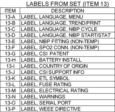
186
187

188
189

190
191

192
193

194
195

196
197

198
199

200
201

202
203

204
205

206
207

208
209

210
211
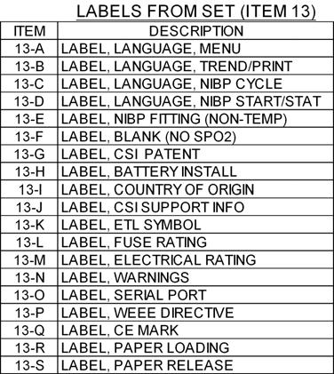
212
213

214
215

216
217
218
219

220
221 REVISIONS NOTES: REV. DATE DESCRIPTION BY /7/05 SEE ECN #8590 DBL PART NO. REV. DESCRIPTION 9949A A BASE ASSEMBLY, NON-TEMPERATURE BASE ASSEMBLY, TEMPERATURE 9949A00 BASE ASSEMBLY, NO SPO, NON-TEMP 9949A004 BASE ASSEMBLY, NO SPO, TEMPERATURE. CSI RESERVES THE RIGHT TO INSPECT THIS ITEM AT THE VENDORS FACILITY. VENDOR'S INSPECTION SYSTEM AND MANUFACTURING PROCESS ARE SUBJECT TO REVIEW/APPROVAL, VERIFICATION AND ANALYSIS BY AUTHORIZED CSI REPRESENTATIVES. ALL CHANGES IN DESIGN, COMPONENTS, PROCESSES OR FABRICATION MUST BE AUTHORIZED IN WRITING BY CSI PRIOR TO IMPLEMENTATION. ALL DEVIATIONS FROM DRAWINGS, SPECIFICATIONS, OR OTHER REQUIREMENTS MUST BE REPORTED TO CSI FOR APPROVAL PRIOR TO SHIPMENT. 0/4/06 SEE ECN #865 05/0/06 SEE ECN # /0/06 SEE ECN #8908 SC TLR SC A005 0 BASE ASSEMBLY, NO SPO, PLASMA CENTER 7 TORQUE TO 5 IN/LBS. (4-PL) 8 5 TORQUE TO 5 IN/LBS. (4-PL) 9 6 SPO CABLE (SPO UNITS, A00, A00 ONLY) FOAM PAD (SPO UNITS ONLY) 0 TORQUE TO 5 IN/LBS SW (TEMPERATURE UNITS ONLY) DRAWN BY: DATE: SCALE: SC NTS TOLERANCE UNLESS OTHERWISE SPECIFIED: XX: +/-.00 XXX: +/-.005 ANGLES: +/- DEGREE CHECK BY: RELEASE DATE: DO NOT SCALE PRINT ENG. APPR.: Q.A. APPR.: MFG. APPR.: S. COOGAN 7//05 A. KAPLAN 7//05 B. LEWANDOWSKI 7/5/05 CONFIDENTIAL: THIS DOCUMENT CONTAINS CONFIDENTIAL INFORMATION AND MAY NOT BE COPIED OR DIVULGED WITHOUT WRITTEN CONSENT OF CRITICARE SYSTEMS, INC. TITLE: BASE ASSEMBLY, 506N PART NO.: DIST: 9949AXXX 0 SHEET OF REV. 4
222
223
224 APPLY PART NO. & REV. LABELS TO FRONT SURFACE OF CHASSIS REV. REVISIONS DATE DESCRIPTION BY SEE ECN #857 SC SEE ECN #8590 RWK SEE ECN #8908 SC (TORQUE TO 5 IN/LBS 4-PL) 7 TORQUE TO 5 IN/LBS (4-PL) 8 #6 CUP WASHER (8-PL) 9 TORQUE TO 5 IN/LBS (4-PL) SW NOTES: DETAIL -A- FINISHED CHASSIS ASSEMBLY. CSI RESERVES THE RIGHT TO INSPECT THIS ITEM AT THE VENDORS FACILITY. VENDOR'S INSPECTION SYSTEM AND MANUFACTURING PROCESS ARE SUBJECT TO REVIEW/APPROVAL, VERIFICATION AND ANALYSIS BY AUTHORIZED CSI REPRESENTATIVES. ALL CHANGES IN DESIGN, COMPONENTS, PROCESSES OR FABRICATION MUST BE AUTHORIZED IN WRITING BY CSI PRIOR TO IMPLEMENTATION. ALL DEVIATIONS FROM DRAWINGS, SPECIFICATIONS, OR OTHER REQUIREMENTS MUST BE REPORTED TO CSI FOR APPROVAL PRIOR TO SHIPMENT. DRAWN BY: DATE: SCALE: SC : TOLERANCE UNLESS OTHERWISE SPECIFIED: XX: +/-.00 XXX: +/-.005 ANGLES: +/- DEGREE CHECK BY: RELEASE DATE: DO NOT SCALE PRINT ENG. APPR.: Q.A. APPR.: MFG. APPR.: CONFIDENTIAL: THIS DOCUMENT CONTAINS CONFIDENTIAL INFORMATION AND MAY NOT BE COPIED OR DIVULGED WITHOUT WRITTEN CONSENT OF CRITICARE SYSTEMS, INC. S.COOGAN 07//05 A.KAPLAN 07//05 LEWANDOWSKI 07/8/05 TITLE: CHASSIS ASSEMBLY 506N PART NO.: DIST: 95746A00 0 SHEET OF REV.
225
226 REVISIONS REV. DATE DESCRIPTION BY 8//05 SEE ECN #849 DBL /6/05 SEE ECN #8590 RWK V.50" LONG /8/06 SEE ECN #8707 DBL 4 08/5/06 SEE ECN #8908 RWK V " LONG 0 SOLDER RED WIRE TO PUMP TERMINAL MARKED"+" TWIST WIRE LEADS (APPROX. TURN PER /") (SEE 95576A00 DRAWING) 4 INSTALL WITH ARROW POINTING AWAY FROM PUMP 5." LONG " LONG.0" LONG 6 8 (4-PL).00" SW NOTES:. CSI RESERVES THE RIGHT TO INSPECT THIS ITEM AT THE VENDORS FACILITY. VENDOR'S INSPECTION SYSTEM AND MANUFACTURING PROCESS ARE SUBJECT TO REVIEW/APPROVAL, VERIFICATION AND ANALYSIS BY AUTHORIZED CSI REPRESENTATIVES. ALL CHANGES IN DESIGN, COMPONENTS, PROCESSES OR FABRICATION MUST BE AUTHORIZED IN WRITING BY CSI PRIOR TO IMPLEMENTATION. ALL DEVIATIONS FROM DRAWINGS, SPECIFICATIONS, OR OTHER REQUIREMENTS MUST BE REPORTED TO CSI FOR APPROVAL PRIOR TO SHIPMENT. DRAWN BY: DATE: SCALE: TOLERANCE UNLESS OTHERWISE SPECIFIED: XX: +/-.00 XXX: +/-.005 ANGLES: +/- DEGREE TITLE: SC NTS CHECK BY: RELEASE DATE: ASSEMBLY, NIBP PNEUMATIC 506N DO NOT SCALE PRINT PART NO.: DIST: ENG. APPR.: Q.A. APPR.: MFG. APPR.: CONFIDENTIAL: THIS DOCUMENT CONTAINS CONFIDENTIAL INFORMATION AND MAY NOT BE COPIED OR DIVULGED WITHOUT WRITTEN CONSENT OF CRITICARE SYSTEMS, INC A00 0 S. COOGAN 7//05 A. KAPLAN 7//05 B. LEWANDOWSKI 7/9/05 SHEET OF REV. 4
227
228 REVISIONS REV. DATE DESCRIPTION BY 09/0/05 SEE ECN #848 0/0/05 SEE ECN #8544 RWK RWK NOTES: 7. CSI RESERVES THE RIGHT TO INSPECT THIS ITEM AT THE VENDORS FACILITY. VENDOR'S INSPECTION SYSTEM AND MANUFACTURING PROCESSES ARE SUBJECT TO REVIEW/APPROVAL, VERIFICATION AND ANALYSIS BY AUTHORIZED CSI REPRESENTATIVES. ALL CHANGES IN DESIGN, COMPONENTS, PROCESSES OR FABRICATION MUST BE AUTHORIZED, IN WRITING, BY CSI PRIOR TO IMPLEMENTATION. ALL DEVIATIONS FROM DRAWINGS, SPECIFICATIONS OR OTHER REQUIREMENTS MUST BE REPORTED TO CSI FOR APPROVAL PRIOR TO SHIPMENT. TORQUE TO 5 IN/LBS. (-PL) 8 SW DRAWN BY: DATE: SCALE: SC NTS TOLERANCE UNLESS OTHERWISE SPECIFIED: XX: +/-.00 XXX: +/-.005 ANGLES: +/- DEGREE CHECK BY: RELEASE DATE: DO NOT SCALE PRINT ENG. APPR.: Q.A. APPR.: MFG. APPR.: CONFIDENTIAL: THIS DOCUMENT CONTAINS CONFIDENTIAL INFORMATION AND MAY NOT BE COPIED OR DIVULGED WITHOUT WRITTEN CONSENT OF CRITICARE SYSTEMS, INC. S.COOGAN 07/5/05 A.KAPLAN 07/5/05 LEWANDOWSKI 07/5/05 TITLE: PRINTER ASSEMBLY 506N PART NO.: DIST: 95745A00 0 SHEET OF REV.
229
230

231

232
233
234 D C B A GND_ANL /PWR_DN PWR_SW V_ANL GND_.V GND_MOD VREF_.5 D BOOTMODE D D VSS D D "No Code" Turn-off Delay.8 S (Typ.) Q4.76 S (Min.) TP04 7. S (Max.) EMUL_MODE R4 00K.B D Watchdog "Enable" "Disable" WDT_DEFEAT.D SW_CLSD PWR_UP DPLY_CS DPLY_CS4 MODULE_LOGIC GROUND D SW_CLOSED.D DPLY_CS DPLY_CS TEMP_SIG IBATT_MON VBATT_MON /SW_PULSE WDT_DEFEAT /WDTOVF DIG_PWR_ON Run Mode "Normal" "Emulation" NOTE: S IS NOT CONTAINED ON PRODUCTION UNITS. FOR DEVELOPMENTAL USE ONLY. D D D.B AC_POWER OFF/ON 5 D.D /BOOT V_ANL DPLY_DAT DPLY_CLK D /.D_FAIL D D CRA8 4 5.D 6 7 EMUL_MODE.B D PLLVcc PLLVss POWER CONTROL AND VOLTAGE MONITORS R0 0.0K D.D BATSTAT0 BATSTAT TEMP_SIG IBATT_MON VBATT_MON COM_RXD C89 00 pf COM_TXD LO_VOLTS SYS_ON/OFF.B GUARD /RESET R9 0.0K COL COL COL /WDTOVF CRA CRA 00K X 4 4.7K x 4 8 ROW4 8 7 ROW 7 6 ROW ROW DPLY_CS4.D CRA6 7 DPLY_CS J7 0K x 4 6 DPLY_CS 5 4 DPLY_CS D CRA5 AC_LED 4 /5V_FAULT 4 5 DPLY_CLK 6 5 DPLY_DAT /BATT_FAIL /V_FAULT TEMP_RXD 00K X 4 TEMP_TXD CRA5A BACKLIGHT DISPLAY BOARD 8.D PWR_UP D 5V TONE CONNECTOR CLP-06-0-L-D-BE (BOTTOM ENTRY) C4 + T R 0.0K Q6 TN06 CRA8A 8 TP9 00K X 4 C80.0 R 49K R4 00 TP4 CRA K x R C R 00K R5 00K 74AC U4B U5C 74HC00D U4A 74AC S DNI ON R4 00K C R K R68 00K R5 0.0K U C65 C64 LM4040BIM CRA4 4 ANALOG GROUND 0K x D C90 EMI_GND 00 pf.v_logic EMI SHIELD GROUND CONNECTION MTG R4.00M CRA K x R0 0.0K 0 R.00K 9 C8..B C7.0 6V R69 0.0K R54 00K U4C 74AC 0 9 C56. TP5 D 74AHC08 R6 0.0K 4 C69.0 U9C R45 0.0K R5 0.0K Q FDN7N 8 74AC CRA5 8 C 5 pf C 5 pf 00K X 4 CRA6 47 x 4 C7 4 UD R 00K C5 C68 0 T.0 C.0 6V 0 T 6V 74HC00D U5D 4 6 D6 4 /PRN_FLAG PRN_ERR PRN_ERR0 /PRN_ERROR AUDIO_VOL LCD_CNTRST VREF_.5 /PWR_DN P5 SCK SDA SPO_RXD SPO_TXD R7 U D 00K X 4 PFI NC MR Y 4.00 MHZ C46..D D C5.0 BAT54A VCC GND R 49.9 OHM 8.B D C7. D + C6 0 T D C49. RES RES /REBOOT D.D /BOOTMODE_RESET U PFO 5 TP6 and TP0: 5mS - 0mS, 80mS TYP TP6 UC 74AC MAX708ESA-T 4 74AHCG08 TP XTAL EXTAL PF7/CLK0 MD MD MD0 EMLE /RES /STBY 9 C58.0 C5.0 C5.0 C4.0 TP0 0 C57.0 C9.0 C54.0 C60.0 D PF/IRQ5/LCAS/DQML PF/IRQ4/UCAS/DQMU PF0/WAIT WDTOVF 4 5 D D /.D_FAIL OFF/ON U9D 74AHC08 6 U5A 74HC00D U5B 74HC00D. 4 74AHC08 D U9B 6.D VCC 4 VCC 7 VCC 98 VCC 99 U7 HD64F78R P7/PO5/TIOCB/TCLKD/EDRAK P6/PO4/TIOCA/EDRAK P5/PO/TIOCB/TCLKC P4/PO/TIOCA P/PO/TIOD0/TCLKB P/PO0/TIOCC0/TCLKA P/PO9/TIOCB0 P0/PO8/TIOCA0 P7/PO7/TIOCB5/(IRQ5) P6/PO6/TIOCA5/(IRQ4) P5/PO5/TIOCB4/(IRQ) P4/PO4/TIOCA4/RxD4/(IRQ) P/PO/TIOCD/TxD4/(IRQ) P/PO/TIOCC/(IRQ0) P/PO/TIOCB/(IRQ9) P0/PO0/TIOCA/(IRQ8) P97/AN5/DA5 P96/AN4/DA4 P95/AN/DA P94/AN/DA P9/AN P9/AN0 P9/AN9 P90/AN8 AN7/P47/DA AN6/P46/DA0 AN5/P45 AN4/P44 AN/P4 AN/P4 AN/P4 AN0/P40 VREF AVCC AVSS P50/TxD/IRQ0 P5/RxD/IRQ P5/SCK/IRQ P5/ADTRG/IRQ P5/SCK/SCL0/(OE)/{CKE} P4/SCK0/SCK4/SDA0 P/RxD/SCL P/RxD0/IrRxD/SDA P/TxD P0/TxD0/IrTxD PLLVcc PLLVss VSS VSS VSS VSS VSS VSS VSS VSS B C8 TO PIN 98 TO PIN 4 + C6 0 T 4 5 /RES_IN D R 00K TP7 SW_CLSD /5V_FAULT /BATT_FAIL /V_FAULT LO_VOLTS PG6 PG5 PG4 /REBOOT.D D.B R 00K COM_CTS D BOOT_DISABLE /EXT_IO /EXT_RAM /EXT_FLASH SPO_ON/OFF /SPO_BOOT TEMP_ON/OFF TEMP_TALK_MODE NIBP_OFF NIBP_BOOT NIBP_RXD NIBP_TXD /NIBP_PGM_ST D AC_POWER 4 + C6 NOTE: U7 MUST BE PROGRAMMED. 0 T SEE REF ON BOM FOR CORRECT SOFTWARE AND REVISION LEVEL. PBUSY PA7/A/IRQ7 PA6/A/IRQ6 0 /COM_CTS PA5/A/IRQ5 9 /COM_DSR PA4/A0/IRQ4 8 PA/A9 7 0 PA/A PA/A PA0/A6 6 7 PB7/A5 0 PB6/A4 4 9 PB5/A PB4/A PB/A 7 0 PB/A PB/A PB0/A PC7/A7 0 PC6/A6 4 9 PC5/A5 5 8 PC4/A PC/A 8 0 PC/A PC/A PC0/A CRA5CRA7CRA8 CRACRA 47R 00pF PD7/D5 PD6/D4 PD5/D PD4/D PD/D PD/D0 PD/D9 PD0/D8 PE7/D7 PE6/D6 PE5/D5 PE4/D4 PE/D PE/D PE/D PE0/D0 PF/LWR 87 PF4/HWR 88 PF5/RD 89 PF6/AS 90 C7.0 C8.0 C59.0 C48.0 NMI DCTL R7 0.0K PG6/BREQ PG5/BACK PG4/BREQ0 0 PH/CS7/(IRQ7)/OE/CKE PH/CS6/(IRQ6) PH/CS5/RAS5/SDRAM_clk PH0/CS4/RAS4/WE PG/CS/RAS/CAS PG/CS/RAS/RAS PG/CS PG0/CS0 P65/TMO/DACK/IRQ P64/TMO0/DACK0/IRQ P6/TMCI/TEND/IRQ P6/TMCI0/TEND0/IRQ0 P6/TMRI/DREQ/IRQ9 P60/TMRI0/DREQ0/IRQ8 P85/(IRQ5)/SCK/EDACK P84/(IRQ4)/EDACK P8/(IRQ)/RxD/ETEND P8/(IRQ)/ETEND P8/(IRQ)/TxD/EDREQ P80/(IRQ0)/EDREQ VCL U0D R4 00K AHC08 UB R55 0.0K 74AC R R 00 C C6. COM_DTR U9A 74AHC CRA /RESET.D COMP5 COMP COMPA RST 4.D /LWR /HWR /RD 47R 00pF 4 D MD5 MD4 MD MD MD MD0 MD9 MD8 MD7 MD6 MD5 MD4 MD MD MD MD0 CRA4 0K x COM_RTS /COM_CD R0 0.0K R56 00K U0 DNI VCC5 VCC VCCA D 74AC C4 00 pf.b D GND 4 4 U4D C4.0 6V GND_.V D MA0 MA9 MA8 MA7 MA6 MA5 MA4 MA MA MA MA0 MA9 MA8 MA7 MA6 MA5 MA4 MA MA MA MA0 CRA9 CRA CRA CRA CRA7 0K x CRA CRA0 0K x 4 0K x CRA0 0K x 4 4 TEMP_TXD TEMP_TALK_MODE /PWR_FAIL R08 00 R9 00 5V AUDIO_VOL D C8. D.D D FAN_ON /ISO_ON D.D MA MA MA MA4 MA5 MA6 MA7 MA8 MA9 MA0 MA MA MA MA4 MA5 MA6 MA7 MA8 MA9 MA0 /RESET /FWR /RD /EXT_FLASH MD[0..5] MA[0..0] EEPROM = 0xA0, WRITE 0xA, READ SDA.D SCK RTC = 0xD0, WRITE 0xD, READ C9. 7 Y.768KHZ R9.D U0A 74AHC08 U0B 74AHC08 R4 475 AC_PWR D 6.B V D E0 BLMBDSNB M x 6 /EXT_FLSH = 0x x0FFFFF (048K) / 0xFFFFF (097K) U9 AM9LV800B SCK SDA D A0 A A A A4 A5 A6 A7 A8 A9 A0 A A A A4 A5 A6 A7 A8 NC RESET BYTE WE OE CE 5V DQ0 DQ DQ DQ DQ4 DNI DQ5 DQ6 DQ7 DQ8 DQ9 DQ0 DQ DQ DQ DQ4 DQ5/A-.D.D D V_BATT RY/BY 5 VSS +.0B D V TP MD0 MD MD MD MD4 MD5 MD6 MD7 MD8 MD9 MD0 MD MD MD MD4 MD5 /FWR /LB /UB.D D D RTC Calibration V D.D Q TN06 /EXT_RAM "TEMPERATURE MODULE CONNECTOR" R6 0.0K 0.0K C.0 6V U A0 A A WP U0C 74AHC08 R 475 AT4C64A 4 C84. U TLV45IDBV R6 0K SCL 6 SDA 5 VCC 8 GND 4 R49 0.7K U OSCI OSCO SDA SCL M4T C5 0 T C C5. VCC 8 VBAT OUT VSS R74 75K CRA9 47R 00pF J MOLEX R U4A OPA7EA VCC 7 CRA7 7 0K X R89 4K C87.0 6V MA MA MA4 MA5 /EXT_IO VBATT_FAIL RANGE: 4.64V V, 4.86V NOM R7 0.0K 4 DNI R0 475 C77 R6 475 R8 00K R4 0 OHM R DNI R60 5.0K C6 DNI R5 0.0K + C. F.V R C8 DNI TANT 4 D D MD0 MD MD MD MD4 MD5 MD6 MD7 MD8 MD9 MD0 MD MD MD MD4 MD5 TEMP_RXD TEMP_ON/OFF R0 4.75K R6 8.5K Q5 FDN7N SS4 6 NIBP_TXD +.0B /UB /LB /FWR NIBP_DIGITAL_PWR R /RESET +.0B.B PRDAT_LATCH PRN_LED_CTRL R0 475 SPO_TXD /SPO_BOOT.D "SPEAKER VOLUME CONTROL" U9C LVC06A. U4 A B C G GA GB GND C44 5 Q IRF78 74LVC8AD Q FDN7N R8 00 C R 00K 00 EL 5V LOW ESR Y0 Y Y Y Y4 Y5 Y6 Y7 DQ0 DQ DQ DQ DQ4 DQ5 DQ6 DQ7 DQ8 DQ9 DQ0 DQ DQ DQ DQ4 DQ5 W UB LB E VCC 6 E6 BLMBDSNB VCC 5V 5V /RD 5K x 6 Icc=40mA E BLMBDSNB /NIBP_TXD /NIBP_BOOT NIBP_BOOT SPKR+ SPKR-.D D D MA MA MA MA4 MA5 MA6 MA7 MA8 MA9 MA0 MA MA MA MA4 MA5 MA6 MA7 MA8 MA9 /EXT_RAM = 0x xFFFFF (048K) R R86 DNI VCC R Q7 FDN7N U8 M68AW5M A0 A A A A4 A5 A6 A7 A8 A9 A0 A A A A4 A5 A6 A7 A8 8 D0 MD94. R87 0 OHM U9D C47 R0 0.0K G 4 74LVC06A D.D R9 00 MA0 /LCD_SEL TONE /EXT_IO MA /NIBP_RXD NIBP_ON/OFF PRGM_ST/SP.D.D D V NIBP MODULE CONNECTOR 9 C55. D V U5A MD8 MD9 MD0 MD MD MD MD4 MD5 MD8 MD9 MD0 MD MD MD MD4 MD5 PRN_LED_CTRL 4 U 74LVCG4 SPO MODULE CONNECTOR C76.0 R48 C40 470pF E5 BLMBDSNB DNI J J.00K MOLEX J MOLEX JST B B-PH-SM-TB R09 0.0K R5 0.0K R0 DNI R5.00K R00 0.0K R LVC0A U5C 74LVC0A R C98 U9F. R6.00K 74LVC06A PG4 P5 /WDTOVF /RES_IN PG5 PG6 /RESET D D GND VCC B8 B7 B6 B5 B4 B B B LCD_SEL NIBP_OFF.D 5V D D SPO_ON/OFF.D D.D D /LCD_SEL /PRNRST /PFEED PSEL /PRNSTRB RECT_LED AX_LED ORAL_LED ALM_SIL_LED.D D D 0x40000 = WRITE INSTR. REG 0x4000 = WRITE DATA RAM 0x4000 = READ INSTR. REG 0x4000 = READ DATA RAM U6 A8 A7 A6 A5 A4 A A A 74LVC45ADW U8 OE 9 DIR }.D VALID ADDR 0x40008 PRINTER AND LED 0x40009 = CONTROL REG 0x4000A (WRITE ONLY) 0x4000B R94.00K R R 00K D D D D4 D5 D6 D7 D8 CLK OE C. 4 U9B 74LVC06A CRA8 47 X 4 CRA6 47 X Q Q Q Q4 Q5 Q6 Q7 Q8 74LVC574A R44 00K U5B 74LVC0A D BAT54S R DNI R9.00K U5D 74LVC0A VCC 0 GND 0 D7 BAT54S C4. 4 D /NIBP_PGM_ST.D R 00 R8 00 A0_EXT A_EXT D.D /PWR_FAIL MD[0..5] } VALID ADDR 0x x x x40007 R8.00K 74LVC06A U9E R85 C8. 4 SPO_RXD.D DNI R K NIBP_RXD CRA 4.7K X 8 CRA6 0K x 4 R8 0 OHM CRA4 00K X 4 RECT_LED AX_LED MD8 MD9 MD0 MD MD MD MD4 MD5 ORAL_LED BACKLIGHT D ALM_SIL_LED P V R6 4K = PRINTER DATA (WRITE ONLY) DNI Renesas Emulator Connector (for Development Only) V U9A 74LVC06A 4 REG_SEL R/W LCD_SEL D0 D D D D4 D5 D6 D7 PRDAT_LATCH D D D D D.D U4B 7 OPA7EA D D.D J /PRN_FLAG9 /PRN_ERROR PRN_ERR0 PRN_ERR PBUSY /PRNRST /PFEED PSEL /PRNSTRB Q TN06 Q5 TN06 Q TN06 Q4 TN R5 00K D D D ELECTRONIC FILE NAME: LCD_CNTRST LCD CONNECTOR (BOTTOM ENTRY) SAMTEC SSM-6-L-SV-BE Q MMBT440 R7 0 R99 0.0K U D D D D4 D5 D6 D7 D8 CLK OE Q Q Q Q4 Q5 Q6 Q7 Q8 74LVC574A U7 D 74LVC44ADW OE GND 0 OE VCC 0 Y4 A4 7 Y A 5 Y A Y A A4 Y4 A Y 4 A Y 6 A Y 8 R49 R76 6.8K R5 00K VCC 0 GND 0 D8 R48 R75.00K.D MMBZ5V6ALT 5.6V PCB NUMBER: 867B00 R0 DRAWN BY: J. Gupton SEPT04 LAST MODIFIED DATE: Tuesday, July 9, 005 CHECKED BY: 0.0K C0.0 6V C70. R40 NOTES:. ALL RESISTORS ARE %, /0W UNLESS OTHERWISE NOTED.. ALL CAPACITORS ARE IN uf UNLESS OTHERWISE NOTED.. LAST DESIGNATORS USED: BATT, C6, CRA6, D9, E, F, J, L5, MTG, P, PWR7, Q, R0, RT, T, TP5, TVS6, U44, Y CRA9 470 X 8 PBUSY_IN SMAJA TVS6 TVS TVS5 TVS C D V LED_PWR RECT_CA AX_CA OR_CA RED_CA R6 R74 0.0K 0.0K R6 ROW R7 0.0K ROW 0.0K R7 ROW R60 0.0K ROW4 0.0K R7 PWR_SW R59 0.0K 0.0K C DNI D5 ZC5800E ZC5800E ZC5800E D D D COL COL COL GND_.V Crossroads Circle Waukesha, WI 586 Copyright C 005 ENG. APPR. Q.A. APPR. MFG. APPR. PRINTER INTERFACE D0 D9 D4 D D4 R80 DNI D5, D9, D0 MMBZ5V6ALT 5.6V.D D D PBUSY_IN /PRN_FLAG J:\PERM\GEMINI\HW\MAIN BOARD\SCHEMATIC\REV \984S00R.DSN J. Gupton 4/7/005 A. Kaplan 4/7/005 B. Lewandowski 4/7/005 TVS4 SMAJA REV DATE DESCRIPTION 9JUL05 SEE ECN #840 CRA 470 X R4 0.0K TVS SMAJ5.0A R99 DNI J 5V BD0 BD BD BD BD4 BD5 BD6 BD7 5V 5P GUARD_GND 5P 5P BOOT_DISABLE /ERROR ERR0 ERR PRNPS /PRST /FEED /SEL /STRB BD0 BD BD BD BD4 BD5 BD6 BD7 BUSY /PF /ERROR ERR0 ERR PRNPS /PRST /FEED /SEL /STRB BUSY /PF CONFIDENTIAL: This document contains confidential information and may not be copied or divulged without written consent of CRITICARE SYSTEMS INC. PART NUMBER: C7 0 T 6V CRA0 K X FRONT PANEL MEMBRANE CONNECTOR TP4 984S00 REV. TITLE: SCHEMATIC, MAIN BOARD, 506N SERIES D 06 SHEET SIZE: DIST: SHEET OF J4 J DNI Alternate Printer Connector (For FFC Cable) PRINTER CONNECTOR MOLEX LVC / HCT COMPATIBLE I/O MAIN DIGITAL SECTION D C B A
235 D C B INPUT VDC NOMINAL Q DO500P-68HC TP5 VIN TP0 AC_LED SI445BDY V_BATT J0 8 L5 F 7 D9 F PLUS_IN BATT_CHG BATT_PLUS 6 5 T 5A 5V 68 uh SS4 T 7A 5V C0 D6 R EXT_GND + J MOLEX C9 R68 R86 D 0 EL. DNI.00K 0.0K SS4 DNI C8 RED 6V + C BLK LOW ESR 0 EL. LED's are mounted on PCB and not intended 6V to be seen by the user. D7 Q7 LOW ESR MOLEX For testing and dianostic use only. MMBT440 C DNI R4 0. W BATT DNI 6V at 7 AH MINIMUM VIN STAT STAT 0 BATT_RTN Battery wires to be D D4 + C Q8 8AWG SML-LX06GC T MMBT440 R R58 SML-LX06IC DNI V_ANL R89 STAR GROUND POINT These traces must 0.K RED GREEN.00K U6 SEE VIEW "A". originate from R/R4 4 TEMP_SIG R9 RSET U40 lands. RT V+ VO R87 8 AC_PWR.00K 8.5K RSET OUT 5 GND R88.00K R79 R78 R K R0 CS+ 6 NC 5 R57 0.K 0.K C5 CT I_SENSE GND CS- 7 9 NC0805KH0J R77 OSC Q 4.99K.00 RTHM LM0BIM.4K R8 TN06 7 R66 STAT0 CHGENB K 0 OHM AC Power VLOGIC STAT RS nd resistor may be used to "tweak" float voltage Sense Input To R80 R96ROVC R8 V_BATT VA- CPU 4.99K 6.9K VLOGIC V_ANL BATSTAT 00K R90 RS R90 VBATT_MON = 0 V TO.50 V TP8 BATSTAT0 C4. STATLV 8 Q0 9 56K FOR V_BATT = 5.00 V TO 7.50 V TN06 OVCTAP 54K RS4 UA (NOTE: V_BATT = BATTERY VOLTAGE R9 C7 BY DESIGN) PLLVss To up input ROVC R67 OP96GS EXT_GND CRA5 5 CSO VAO VBATT_MON 0K x GND_ANL.0K UC909DW DNI DNI GND_MOD R65 R77 C8 87K C4 CHARGE STATUS LED 00K GND_.V D 4 CAO CA- DNI STAT 0 STAT R76 ANALOG D MODULE_LOGIC R9 DNI GROUND GROUND (GRN) (RED) R84 R9 VREF_.5 5.6K R8 MTG OFF OFF Trickle Charge, Defective 9.5K 6.9K 00K C.V_LOGIC RG R85 C88 Battery or No Input Power POWER RG RS GROUND.0 6V DNI R0 GROUND On OFF Bulk Charge 4.0K /AC_POWER 00K C.0047 R79 ALL GROUND SYMBOLS ARE PLANES OFF On Over Charge 470pF AND JOINED TO POWER GROUND BY R9 IBATT_MON = 0 V TO.50 V R56 50 MIL (MIN) TRACE AT LOCATION SHOWN On On Float Charge (Full Charge), Q6 0.0K 0.K FOR I_SENSE = 0 A TO 4.5 A AC_POWER TN06 I_SENSE 6 ON 984M00 DRAWING. Defective or No Battery Connected 7 IBATT_MON 0.0K 5 UB VIEW "A" L OP96GS D4 R78 C uh ZC5800E 7.K U TP + C8 DO50P- V_RAIL LP950CDT-..B 00 EL C9 Standby Power Supply 5V. R5 TP LOW ESR 0.0 5V 5P VI VO C0 PWR7 C0 C99 D5 C6 + C + 0 T. 0 T 00 T SS4 C7 C6 L + + C KHZ ON BATT PWR U8.0 6V 00 T. R8 Design Specs. 00 KHZ ON AC PWR R04 LOW ESR Q5 uh 6V R LOW ESR 60.4K / W 5 Volt at Amp, TO 5 Package 7 DO50P- FA/SD DR 6 IRF78 4 Amp Peak SEPIC V_BATT LM478MM R04 R6 Vin 5.5 to. Volts 40.K COMP ISEN R9 C95 FB 0 OHM E4 00K C9 R05 V_ANL 00 pf 0.0K BLMBDSNB.0 R E C7 PLLVcc /AC_POWER Q0 49.9K R07 R6 C94 BLMBDSNB J5 TN06 R9.0 OHM DNI TP8 VIN V_RAIL 4.75K.0 V_RAIL..D VCC U7 L D To An Optional V Fan DNI VIN SW 4 V_BATT Q6 VIN SW SS4 5 uh C SI445BDY VIN D8 C9 LM65MTC-. DT6P- + C79 D + 8 L4 C74 7 Q7 AVIN FB 9 D 0 EL. SS4 7 Q9 00 EL. SS4 5V Diode protects against output voltage SI445BDY SS4 6 0 uh DNI 5V 0 LOW ESR being pulled below ground through the 8 SW_VRAIL COMP 5 R0 LOW ESR synchronous FET in an undervoltage 7 FAN_ON 8 SS/SD input situation. 6 C + 5 DNI C85 R7 00 EL C07 R5 R8 00K 5V. R7 TP9 R7.00 C75 00K C00 LOW ESR 0.0 V.0047 DNI Design Specs. C06 D7 00K 5.0K. Volt at amp step-down SS4 V_RAIL R64 C C7 Q.0 U + + Vin 5.5 to. Volts C78 R6 TN06 Q0 R06 R05 Q8 R4 00 T..00K 0.0K TN06 /AC_POWER 0.0K 400 KHZ 00 6V / W Q4 VLOGIC 7 0K FA/SD DR 6 IRF78 4 LOW ESR MMBT440 DIG_PWR_ON LM478MM R4 R7 R44 R55 00K 0.0K 40.K COMP ISEN 0 OHM R84 C04 FB Q8 C0 TN06 SYS_ON/OFF R.0.0K 0.0K C4 00 pf R8 R5 00K R.0 OHM Q.0 /AC_POWER TN K Design Specs. Volt at amp step-up Vin 5.5 to. volts AGND VIN 8 AGND PGND VIN 8 PGND VCC 4 GND AGND AGND VCB PGND PGND PGND NC GND D C B A A ELECTRONIC FILE NAME: J:\PERM\GEMINI\HW\MAIN BOARD\SCHEMATIC\REV \984S00R.DSN POWER SUPPLY SECTIONS PCB NUMBER: 867B00 R0 DRAWN BY: R. Henning JUN04 J. Gupton SEPT04 LAST MODIFIED DATE: Tuesday, July 9, 005 CHECKED BY: 095 Crossroads Circle Waukesha, WI 586 Copyright C 005 ENG. APPR. Q.A. APPR. MFG. APPR. CONFIDENTIAL: This document contains confidential information and may not be copied or divulged without written consent of CRITICARE SYSTEMS INC. PART NUMBER: 984S00 REV. TITLE: SCHEMATIC, MAIN BOARD, 506N SERIES D 06 SHEET SIZE: DIST: SHEET OF 5 4
236 D D C C45.0 6V Break Detection Time: 8 ms to 9 ms 55 ms TYP R0 00K D R TP U4B 74LVC0A.D.B R40 DNI R4 REMOVED AND R40 INSTALLED FOR "WAKE ON COM" OPTION. COM_RXD U4A 74LVC0A D5 ZC5800E R 00K R4 0 OHM /COM_CTS R6 00K TP._COM COM_CTS R4 00K R8 00K UA /COM_DSR D8 BAT54C 74AC U4C 74LVC0A D9 ZC5800E R0 00K GND_.V 74HC4 8 BOOT_DISABLE SW_CLOSED OFF/ON U5D U4D 74LVC0A SEE NOTE D 9 /COM_CD /ISO_ON COM_DTR COM_TXD._COM.V_LOGIC GROUND COM_RTS R94 0.0K R57 00K D._COM D TP6 TP5 R06 0.0K U5F 74HC4 Q9 MMBT440 + C4 T D 7 4._COM C08..D D.D U5C R5 0.0K R45 0.0K GND D GND U MAX5 SD D Vcc U5B R HC4 R U5A R46 0.0K 74HC4 R70 74HC4 R47.00K R95 0.0K._COM D._COM 8 D D D ISOLATION BARRIER (8 mm) U6 U5 U4 6N6 6N6 6N6 DNI D BAT54C 6N6 6N6 6N6 U9 U8 U4 U7 5 6 C T EPC6G-._ISO._ISO R54 R9 0.0K 4 R98.00K R69 R4 4 R97 0.0K D7 SS4 C DNI._ISO R70._ISO Q9 TP04 +.5V Nom. (Unregulated) R96 DNI DNI C9 + 0 T D6 SS4 C. TP C96. +._ISO C. C9 47 EL 6 V /DTR Tx /RTS /DSR /CD /CTS Rx U0 LP950CDT-. VI GND TO 5 Package C05. R5 4 VO C5 + 0 T C+ C+ V+ VCC T_IN T_IN T_IN R_OUT R_OUT R_OUT R4_OUT R5_OUT EN /DTR TP4 C6.._ISO D6 BAT54A D._ISO C+ U6 ADM0EARU C- 4 C- C- V- ISO_GND GND 7 T_OUT T_OUT T_OUT BAT54A 0 R_IN 9 R_IN 8 R_IN 7 R4_IN 6 R5_IN 5 SD TP R65 0.0K C09. C0. E BLA6B47SD BLA6B47SD4 E._ISO U4 CTS 4 475K C5. 74AHCG08 R D ZC5800E RI DTR CTS TD RTS RD DSR CD TP7 R7 GUARD_GND EXTERNAL COM (RS) MEMBRANE SHIELD CONNECTION RS- NOTES:. CONTROL SIGNALS ARE POSITIVE LOGIC (LOGIC IS POSITIVE VOLTAGE).. DATA SIGNALS ARE INVERSE LOGIC (LOGIC IS NEGATIVE VOLTAGE).. TXD IS LOGIC (MARK) STATE WHEN IDLE. 4. OUTPUT VOLTAGE RANGES: POSITIVE: +5 TO +5 NEGATIVE: -5 TO -5 UNDEFINED: -5 TO INPUT VOLTAGE RANGES: POSITIVE: + TO +5 NEGATIVE: - TO -5 UNDEFINED: - TO S S C0.0 6V P C V MTG P R98 DNI GUARD GROUND CONNECTOR C /BOOT C6.0 6V D8 BAT54C 0 C66.0 6V BOOTMODE R9 00K D FS._COM R8 0 OHM E BLM4PG0SN C6 0 T 6V D C97. D SS4 D0 SS4 B R00 0.0K R7 0.0K D B D TP U5E D /BOOTMODE_RESET 0 74HC4 BOOT MODE LOGIC R0 00K D PROCEDURE TO FORCE "BOOT MODE":. TURN UNIT OFF. SHORT TP TO TP8 AND TP TO TP8.. CONNECT NULL MODEM CABLE TO SERIAL PORT. 4. START FS DOWNLOAD TOOL. 5. TURN UNIT ON - BOOT MODE WILL COMMENCE (VERIFY WITH DOWNLOAD TOOL) WHEN BOOT DOWNLOAD IS COMPLETE, 6. TURN POWER OFF AND REMOVE AC. 7. REMOVE NULL MODEM CABLE. 8. REMOVE TP,/TP8 AND TP/TP8, SHORTS. A EXTERNAL COM PORT SECTION A ELECTRONIC FILE NAME: J:\PERM\GEMINI\HW\MAIN BOARD\SCHEMATIC\REV \984S00R.DSN PCB NUMBER: 867B00 R0 DRAWN BY: J. Gupton SEPT04 LAST MODIFIED DATE: Wednesday, July, 005 CHECKED BY: 095 Crossroads Circle Waukesha, WI 586 Copyright C 005 ENG. APPR. Q.A. APPR. MFG. APPR. CONFIDENTIAL: This document contains confidential information and may not be copied or divulged without written consent of CRITICARE SYSTEMS INC. PART NUMBER: 984S00 REV. TITLE: SCHEMATIC, MAIN BOARD, 506N SERIES D 06 SHEET SIZE: DIST: SHEET OF 5 4
237
238
239

240
241
242
243
244

245
246 5 4 REV DATE ECN # 7/9/005 SEE ECN #844 D D 5V 5V 5V C ISO_.V ISO_5V I TP6 C. TP C 0 T U LP950CDT-. VO I U LM9AM-5.0 VOUT GND GND GND GND GND 7 6 VI VIN 8 NC 4 NC 5 TP4 6V NOMINAL UNREGULATED C4.00 I C5. C. C 0 T TP8 LOOP I C6 DNI L SM BEAD C7. I C8 00 T D SS4 D SS4 L SM BEAD I L SM BEAD T 4 6 EPC6G- 5 C9. L4 SM BEAD C0 TP TP5 47 E LO ESR 5 V 8 MAX5 ON/OFF U D D 6 GND 7 Vcc TP7 GND 5V Active Low Turns Module "OFF" SD 4 FS NC 5 C. R 00K R 00 R4 00K TP Q TN06 C I I To Main Board To Nellcor OXIMAX SpO Sensor LED_PLUS IN_SHLD DET_ANODE J LED_MINUS DIG_GND MEM_DATA OUT_SHLD DET_CATH R 0K TP0 ISO_5V R5 DNI I C. ISO_5V I 8 U4 5V 5V TP9 LOOP 5V MOD_RX TP J MOD_TX ON/OFF 04-6VC Nellcor MP00 Module Will Plug Into These Two Connectors When Mounted As a Daughter Board RX I N6 LED Current ~9.5 ma R7 65 Q TN06 R8 00 Q4 TN06 R 0K R 00 R9 TP MOD_RX B DET_CATH IN_SHLD DIG_GND LED_MINUS J SFMC-04-0-S-D DET_ANODE OUT_SHLD MEM_DATA LED_PLUS I TX ISO_.V J SFMC-05-0-S-D I RX ISO_5V TX TP4 ISO_5V R7 00K R6 00 ISO_5V Q5 TP04 U5 8 5V C4. R0 DNI 5V R 4.99K TP 00K B LED Current ~9.5 ma R5 65 6N R4 0K MOD_TX.V Logic I A H P.C.B. BARE 864B00 Isolation Barrier ELECTRONIC FILE NAME: PCB NUMBER: 864B00 R DRAWN BY: Roy Henning, August 7, 004 LAST MODIFIED DATE: Monday, April 04, 005 CHECKED BY: J:\PERM\GEMINI\HW\NELLCOR CARRIER\SCHEMATIC\REV \987S00 REV.DSN 095 Crossroads Circle Waukesha, WI 586 Copyright C 004 ENG. APPR. R. Henning 4/0/05 Q.A. APPR. A. Kaplan 4//05 MFG. APPR. NOTES: - ALL RESISTORS ARE %, 060 SIZE, MF, UNLESS OTHERWISE NOTED - ALL CAPACITORS ARE UF CERAMIC, SMT, UNLESS OTHERWISE NOTED - REFERENCE DESIGNATORS NOT USED: R6,Q B. Lewandowski 4//05 CONFIDENTIAL: This document contains confidential information and may not be copied or divulged without written consent of CRITICARE SYSTEMS INC. PART NUMBER: TITLE: 987S00 Nellcor Carrier Board SHEET SIZE: DIST: SHEET OF REV. C 06 A 5 4
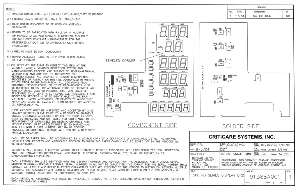
247

248

249
TRANQUILITY VS VERSATILITY IN VITAL SIGNS A M E R I C A S TRANQUILITY VS A M E R I C A S
 VERSATILITY IN VITAL SIGNS PORTABLE weighs less than 6lbs TOUCHSCREEN easy and intuitive to use MOBILE backup battery powered The Tranquility VS is a new and intuitive approach to patient vital signs measurement.
Cardiac Monitoring Catalog USA
 CM Cardiac Monitoring Catalog CRITICARE MONITORS Basic vital signs monitoring in a simple-to-use, lightweight and portable design. This comprehensive cost-effective solutions is perfect for the bedside
Argentine Manufacturer of Hospital Equipment. Electrocardiograph Pulse Oximeters Vital Signs Monitors
 Electrocardiograph Pulse Oximeters Vital Signs Monitors ELECTROCARDIOGRAPH Model: RG-401plus Model: RG-401 ELECTROCARDIOGRAPH Model: RG-401 Technical Specifications Accessories Carrying bag Patient cable
SM-10 SM-20-A. Sound Level Meters. Users Manual. For detailed specifications and ordering info go to
 SM-10 SM-20-A Sound Level Meters Users Manual For detailed specifications and ordering info go to www.testequipmentdepot.com SM-10 / SM-20-A Sound Level Meters English Users Manual SM10_Rev002 2009 Amprobe
Model 515B and 515C. Pulse Oximeter. User s Manual. This manual covers Model 515B (Cat. No ) and Model 515C (Cat. No ) April 17, 1996
 and Model 515C (Cat. No ) April 17, 1996") Model 515B and 515C Pulse Oximeter User s Manual This manual covers Model 515B (Cat. No. 6500-00) and Model 515C (Cat. No. 6550-00) April 17, 1996 Catalog No. 6500-23-02/6550-23-02 Novametrix Medical Systems
Model 515B and 515C Pulse Oximeter User s Manual This manual covers Model 515B (Cat. No. 6500-00) and Model 515C (Cat. No. 6550-00) April 17, 1996 Catalog No. 6500-23-02/6550-23-02 Novametrix Medical Systems
Service Manual. Vital Signs Monitor (52000 Series) Protocol QuikSigns (52000 Series)
 Protocol QuikSigns (52000 Series)") Service Manual Vital Signs Monitor (52000 Series) Protocol QuikSigns (52000 Series) Welch Allyn, Inc. 4341 State Street Road P.O. Box 220 Skaneateles Falls, NY 13153-0220 95P445E Rev. C Copyright 1999
Service Manual Vital Signs Monitor (52000 Series) Protocol QuikSigns (52000 Series) Welch Allyn, Inc. 4341 State Street Road P.O. Box 220 Skaneateles Falls, NY 13153-0220 95P445E Rev. C Copyright 1999
CAS 740 Vital Signs Monitor
 CAS 740 Vital Signs Monitor Service Manual THE CAS 740 VITAL SIGNS MONITOR FEATURES CAS 740-1 CAS 740-2 CAS 740-3 Non-Invasive Blood Pressure and Pulse Rate. Non-Invasive Blood Pressure, Pulse Rate and
XBDM. 1015LV, 1020LV, 1030LV, 1020HV Models USER & INSTALLATION MANUAL BYPASS DISTRIBUTION MODULE
 XBDM 1015LV, 1020LV, 1030LV, 1020HV Models USER & INSTALLATION MANUAL www.xpcc.com 2013 Xtreme Power Conversion Corporation. All rights reserved. Table of Contents IMPORTANT SAFETY INSTRUCTIONS:... 4 INTRODUCTION...
etco 2 SpO 2 IBP medlab 2017/2018 OEM Modules for Patient Monitoring medizinische Diagnosegeräte GmbH
 etco 2 SpO 2 IBP OEM Modules for Patient Monitoring 2017/2018 medlab medizinische Diagnosegeräte GmbH 5 Contents Pulse Oximetry EG00352 Digital Miniaturized SpO 2 -Module 5 PEARL100 SpO 2 -Module with
OPERATING AND SERVICE MANUAL. Universal Interface Device 47
 OPERATING AND SERVICE MANUAL Universal Interface Device 47 MAGNA-POWER ELECTRONICS, INC. 39 ROYAL ROAD, FLEMINGTON, NJ 08822 May 24, 2012 SAFETY NOTICE Universal Interface Device 47 (UID46) connects
Technical Service Manual
 Alaris SpO 2 Modules 820 Series (Nellcor Technology) 8220 Series (Masimo Technology) Supports: Guardrails Suite (v7) Guardrails Suite MX (v8) April 2006 ALARM MONITOR STANDBY %SpO 2 PULSE (BPM) CHANNEL
SHUTTERBOSS VERSION II USER MANUAL
 SHUTTERBOSS VERSION II USER MANUAL 1 INTRODUCTION Thank you for choosing the Vello ShutterBoss. This device is more than just a remote shutter release. It features many timer functions: self-timer, interval
Delta 1600 User Manual
 Delta 1600 User Manual Intended Use: Delta 1600 AED Tester is a precision instrument that simulates various cardiac waveforms and measures discharged energy. It assures AEDs detect the waveforms, audibly
User Manual AIMB-C200. Economical Embedded Chassis for Mini-ITX Motherboard
 User Manual AIMB-C200 Economical Embedded Chassis for Mini-ITX Motherboard Copyright The documentation and the software included with this product are copyrighted 2010 by Advantech Co., Ltd. All rights
*M C* Philips A1 and A3 Patient Monitors M3926A M3923A M3924A M3927A M3928A M3929A. Service Guide. Part Number M C
 Philips A1 and A3 Patient Monitors A1 Models: A3 Models: M3921A M3922A M3923A M3924A M3926A M3927A M3928A M3929A Service Guide Part Number M3921-9000C Printed in the U.S.A. February 2002 First Edition
Installation and Operation Back-UPS BR1000G-IN / BR1500G-IN
 Installation and Operation Back-UPS BR1000G-IN / BR1500G-IN Important Safety Information Read the instructions carefully to become familiar with the equipment before trying to install, operate, service
OPERATING AND SERVICE MANUAL. Universal Interface Device 47
 OPERATING AND SERVICE MANUAL Universal Interface Device 47 MAGNA-POWER ELECTRONICS, INC. 39 ROYAL ROAD, FLEMINGTON, NJ 08822 May 24, 202 SAFETY NOTICE Universal Interface Device 47 (UID47) connects two
Owner s Instruction Manual
 Owner s Instruction Manual Advanced Healthcare Telephone Model 5150 Contents IMPORTANT SAFETY INSTRUCTIONS...3 BOX CONTENTS...4 FEATURES...4 ON/OFF SWITCH...4 DIAL BUTTONS...4 RECEIVER VOLUME CONTROL...4
Integrate with electronic health records (EHRs).
.") Integrate with electronic health records (EHRs). To find out more about how Spot LXi can optimize vitals connectivity in your facility, contact your local sales representative. Ordering Information 450T0**
Integrate with electronic health records (EHRs). To find out more about how Spot LXi can optimize vitals connectivity in your facility, contact your local sales representative. Ordering Information 450T0**
SLA Battery Capacity Analyzer
 Model: 601B SLA Battery Capacity Analyzer USER MANUAL Safety Summary The following safety precautions apply to both operating and maintenance personnel and must be followed during all phases of operation,
Power TracKer VII. User s Manual 2006 AVID. Multi Mode Reader. Manufactured under one or more of the following Patents:
 Power TracKer VII User s Manual 2006 AVID Multi Mode Reader Manufactured under one or more of the following Patents: 5,235,326-5,266,926-5,559,507 6,172,609 FCC ID: IOL-134-AV1028 The device complies with
Instruction and Operation Manual
 SEC IR PC LINK Instruction and Operation Manual Sensor Electronics Corporation 5500 Lincoln Drive Minneapolis, Minnesota 55436 USA (952) 938-9486 Fax (952) 938-9617 email sensor@minn.net or www.sensorelectronics.com
Tx Link. Quick Setup Guide. English. Connection module
 Tx Link Connection module Quick Setup Guide English Introduction The Tx Link connection module provides connectivity between EasyCare Tx software and a positive airway pressure therapy device (therapy
User s Guide. 600A AC Clamp Meter. Model 38387
 User s Guide 600A AC Clamp Meter Model 38387 Safety International Safety Symbols This symbol, adjacent to another symbol or terminal, indicates the user must refer to the manual for further information.
Owner s Manual. 5200mAh Mobile Power Bank
 Owner s Manual 5200mAh Mobile Power Bank Model: UPB-05K2-1U PROTECT YOUR INVESTMENT! Register your product for quicker service and ultimate peace of mind. You could also win an ISOBAR6ULTRA surge protector
Owner s Manual. MWHHM UHF 100 Frequency Wireless Handheld Microphone. MWHHM Wireless Handheld Microphone. AtlasIED.com
 Owner s Manual UHF 100 Frequency 1 AtlasIED.com Owner s Manual Description The AtlasIED wireless handheld microphone is the ideal choice for a variety of applications ranging from classrooms and conference
User Guide. Control Box. RoscoLED TM.
 RoscoLED TM Control Box User Guide This guide applies to the following RoscoLED Control Box models: RoscoLED Control Box 300W/Static White (293 22250 0000) RoscoLED Control Box 400W/VariWhite (293 22260
Manual Version: V1.00. Video Decoder Quick Guide
 Manual Version: V1.00 Video Decoder Quick Guide Thank you for purchasing our product. If there are any questions, or requests, please do not hesitate to contact the dealer. Copyright Copyright 2016 Zhejiang
Surge Protective Devices Installation, Operation and Maintenance Manual. LoadTrack LTL
 LoadTrack LTL Surge Protective Devices Installation, Operation and Maintenance Manual P.O. Box 3760 Winter Park, FL 32790 USA TEL: 800-647-1911 www.tpssurge.com LOADTRACK LTL INSTALLATION, OPERATION AND
The power behind competitiveness. Delta Infrasuite Power Management. Power Distribution Unit. User Manual.
 The power behind competitiveness Delta Infrasuite Power Management Power Distribution Unit User Manual www.deltapowersolutions.com Save This Manual This manual contains important instructions and warnings
Manual Version: V1.00. Video Decoder User Manual
 Manual Version: V1.00 Video Decoder User Manual Thank you for purchasing our product. If there are any questions, or requests, please do not hesitate to contact the dealer. Copyright Copyright 2016 Zhejiang
PW 406. Features &Benefits: Multi parameters Patient monitor
 PW 406 Multi parameters Patient monitor Features &Benefits: 1. 12.1 color TFT display, high resolution 800 600 dpi; 2. Separated para board: ECG, NIBP, SpO2 board; 3. Full touch screen enables intuitive
Accutorr Plus is a U.S. trademark of Mindray DS USA, Inc. Masimo SET and LNOP are registered trademarks of Masimo Corporation.
 Accutorr Plus is a U.S. trademark of Mindray DS USA, Inc. Masimo SET and LNOP are registered trademarks of Masimo Corporation. Nellcor, OxiMax, Oxiband, and Durasensor are U.S. registered trademarks of
Global Water Instrumentation, Inc.
 Global Water Instrumentation, Inc. 11390 Amalgam Way Gold River, CA 95670 T: 800-876-1172 Int l: (916) 638-3429, F: (916) 638-3270 PRODUCT NAME: 3101 Conductivity Controller - 1 - Global Water s Conductivity
Installation and Operation Back-UPS Pro BR700G-TW
 Installation and Operation Back-UPS Pro BR700G-TW Inventory Safety Do not install the UPS in direct sunlight, in excessive heat, humidity, or in contact with fluids. Do not connect a laser printer or hair
User's Guide. MiniTec TM Series Model MN25 MultiMeter
 User's Guide MiniTec TM Series Model MN25 MultiMeter Warranty EXTECH INSTRUMENTS CORPORATION warrants this instrument to be free of defects in parts and workmanship for one year from date of shipment (a
Installation Guide. QBox-V6. Standalone/Spare V6 SDI QBox. Standalone/Spare V6 SDI QBox. Part No. A
 Installation Guide Standalone/Spare V6 SDI QBox QBox-V6 Standalone/Spare V6 SDI QBox Part No. A9009-0004 EN www.autocue.com Copyright 2017 All rights reserved. Original Instructions: English All rights
IRM-5000P. insulation resistance meter. Vanguard Instruments Company, Inc.
 IRM-5000P insulation resistance meter Vanguard Instruments Company, Inc. www.vanguard-instruments.com IRM-5000P insulation resistance meter The IRM-5000P is a microprocessor-based, high-voltage, insulation-test
EOS-6000 Series Optical A/B Switch User Manual DC Version
 EOS-6000 Series Optical A/B Switch User Manual DC Version For more information on this and other products: Contact Sales at EMCORE 626-293-3400, or visit www.emcore.com. Table of Contents Table of Contents...2
Owner s Manual. MWBPT UHF 100 Frequency Wireless Belt Pack Transmitter. MWBPT Wireless Belt Pack Transmitter. AtlasIED.com
 Owner s Manual UHF 100 Frequency 1 AtlasIED.com Owner s Manual Description The AtlasIED wireless belt pack transmitter is the ideal choice for a variety of applications ranging from classrooms and conference
Duo is a U.S. trademark of Mindray DS USA, Inc. Navigator is a U.S. trademark of Mindray DS USA, Inc.
 Duo is a U.S. trademark of Mindray DS USA, Inc. Navigator is a U.S. trademark of Mindray DS USA, Inc. Masimo SET, LNOP and CleanShield are U.S. registered trademarks of Masimo Corp. Copyright Mindray DS
General Warranty. For more details, please refer to the user manual on the supplied CD, it can also be downloaded at
 General Warranty Lilliput warrants that the product will be free from defects in materials and workmanship for a period of 3 years (1 year for accessories) from the date of purchase of the product by the
Telephone Line Monitor USER GUIDE
 Telephone Line Monitor USER GUIDE For Technical Assistance call the Manufacturers direct Ph 800 530 8645 8AM - 5PM West Coast Pacific Time NATCOMM USA LLC Responsible Supplier Code NC OPERATION Our Telephone
LPM Series. LPM Series User s Manual
 LPM Series LPM Series User s Manual i Warranty Newport Corporation warrants that this product will be free from defects in material and workmanship and will comply with Newport s published specifications
Broadband Automatic Disconnect Switch. User Manual
 Reset/Test Primary/ Primary Broadband Automatic Disconnect Switch User Manual Local Power Remote Pwer Local 63V Fault Secondary Select Secondary 220V Normal 990-1929 09/2004 Introduction Introduction
9040/9040UK. Users Manual. Phase Rotation Indicator
 9040/9040UK Phase Rotation Indicator Users Manual PN 2438546 April 2005 2005 Fluke Corporation. All rights reserved. Printed in China All product names are trademarks of their respective companies. LIMITED
PRODUCT SHEET. NON-INVASIVE SMALL ANIMAL TAIL BLOOD PRESSURE SYSTEMS NIBP250 Blood Pressure Amplifier NIBP200A Blood Pressure System
 NON-INVASIVE SMALL ANIMAL TAIL BLOOD PRESSURE SYSTEMS NIBP250 Blood Pressure Amplifier NIBP200A Blood Pressure System NIBP Amplifiers with built-in pump automatically inflate the tail cuff to occlude the
INSTRUCTION MANUAL. Model Dual Input RTD Thermometer. Measures two temperatures simultaneously. Dual RTD probe inputs
 INSTRUCTION MANUAL Model 421504 Dual Input RTD Thermometer Measures two temperatures simultaneously Dual RTD probe inputs Clock and Elapsed Timer functions Special functions include Data Hold, MIN/MAX/AVG,
Operations Manual EcoSense ph100
 Operations Manual EcoSense ph100 Portable ph, mv and Temperature Instrument English Français Español Deutsch Italiano WARRANTY The EcoSense ph100 Instrument is warranted for one year from date of purchase
Emerson Network Power provides customers with technical support. Users may contact the nearest Emerson local sales office or service center.
 Liebert PSA iton User Manual Version: V2.8 Revision date: November 14, 2005 Emerson Network Power provides customers with technical support. Users may contact the nearest Emerson local sales office or
INSTRUCTION MANUAL. Models: H100 Light Meter
 INSTRUCTION MANUAL Models: H100 Light Meter Table of Content 1. Product Introduction 3 1-1 Features. 3 1-2 Applications... 3 2. Safety Information 4 2-1 Cautions.... 4 2-2 Safety Symbols.... 4 3. Specifications....
Kinetix 300 Memory Module Programmer
 Kinetix 300 Memory Module Programmer Catalog Number 2097-PGMR Topic About the Memory Module Programmer 1 Parts List 3 Batteries Operation 4 Using Memory Module Programmer 6 Switch On/Off Memory Module
Global Water Instrumentation, Inc.
 Instrumentation, Inc. 11390 Amalgam Way Gold River, CA 95670 T: 800-876-1172 Int l: (916) 638-3429, F: (916) 638-3270 Display: EZ100 11/12/04-1 - Congratulations on your purchase of the EZ100 Display.
USER MANUAL. Uninterruptible Power Supply Line-interactive VCL Series UPS VA. GE Critical Power
 Critical Power USER MANUAL Uninterruptible Power Supply Line-interactive VCL Series UPS 400 600 800 1000 1500 VA GE Consumer & Industrial SA General Electric Company CH 6595 Riazzino (Locarno) Switzerland
Benchmark Plus Microplate Reader User Manual. This Instrument for Laboratory Use Only Rev C
 Benchmark Plus Microplate Reader User Manual This Instrument for Laboratory Use Only 4100172 Rev C 4100172 Rev C Benchmark Plus System with Incubator Catalog Number 170-6930 Benchmark Plus Reader with
User's Guide. Model RPM10 Laser Photo / Contact Tachometer with IR Thermometer. Patented
 User's Guide 99 Washington Street Melrose, MA 02176 Fax 781-665-0780 TestEquipmentDepot.com Model RPM10 Laser Photo / Contact Tachometer with IR Thermometer Patented Introduction Congratulations on your
BIG BUTTON PHONE WITH ONE TOUCH DIALING AND
 FUTURE CALL LLC BIG BUTTON PHONE WITH ONE TOUCH DIALING AND 40db HANDSET VOLUME MODEL: FC-1507 USER MANUAL Please follow instructions for repairing if any otherwise do not alter or repair any parts of
INSTRUCTION MANUAL. Automatic Blood Pressure Monitor with Arm Cuff. Model HEM-711AC
 INSTRUCTION MANUAL Automatic Blood Pressure Monitor with Arm Cuff Model HEM-711AC ENGLISH ESPAÑOL CONTENTS Before Using the Monitor Introduction..........................................2 Important Safety
Installation and Operation Back-UPS Pro 900
 Us er Documentation Installation and Operation Back-UPS Pro 900 Inventory bu001a User Documentation (2) Safety and General Information Inspect the package contents upon receipt. Notify the carrier and
Agilent 70612B K18 Switch Matrix
 Agilent 70612B K18 Switch Matrix Hardware Reference Manual Agilent Technologies COPYRIGHT 2000 AGILENT TECHNOLOGIES, INC. ALL RIGHTS RESERVED. NO PART OF THIS DOCUMENT MAY BE REPRODUCED IN ANY FORM OR
Network Camera. Quick Guide DC-B1203X. Powered by
 Network Camera Quick Guide DC-B1203X Powered by Safety Precautions English WARNING RISK OF ELECTRIC SHOCK DO NOT OPEN WARNING: TO REDUCE THE RISK OF ELECTRIC SHOCK, DO NOT REMOVE COVER (OR BACK). NO USER-SERVICEABLE
User s Manual. NOVAMETRIX BaseStation for Hand-Held Monitors....simply, the leading edge
 User s Manual NOVAMETRIX BaseStation for Hand-Held Monitors...simply, the leading edge 5 TECHNOLOGY DRIVE WALLINGFORD, CT U.S.A. 06492 1-800-243-3444 203-265-7701 FAX 203-284-0753 http://www.novametrix.com
PowerRING Qi DUAL WIRELESS CHARGING RECEIVER
 PowerRING Qi DUAL WIRELESS CHARGING RECEIVER Please register online www.minibatt.com/register Qi-compatible USER MANUAL minibatt PowerRING.indd 1 25/4/16 12:42 Thank you for selecting minibatt products.
INSTRUCTION MANUAL CAT ecount
 Electron Microscopy Sciences INSTRUCTION MANUAL CAT. 70309-01 ecount Safety precautions The ecount is used specifically in bioscience, medical, and chemistry laboratories. It may come in contact with biohazardous
LG Electronics BLUETOOTH Mono Headset HBM-760 / HBM-761 User manual
 English Español LG Electronics BLUETOOTH Mono Headset HBM-760 / HBM-761 User manual HBM-760 All rights reserved. LG Electronics Inc., 2007 HBM-761 Note : For the best performance and to prevent any damage
Product Documentation
 Product Documentation Emanate PowerPath TM TempTag PPT-300 Date: April 12, 2016 Document Number: PPT200-001 R1.4 Emanate Wireless, Inc. 11145 Windsor Rd. Ijamsville, MD 21754 Telephone: 844-EMANATE Email:
DCS-E 1kW Series, DLM-E 3kW & 4kW Power Supplies
 DCS-E 1kW Series, DLM-E 3kW & 4kW Power Supplies M51A Option: Isolated Analog Programming Manual Power Supplies Elgar Electronics Corporation 9250 Brown Deer Road San Diego, CA 92121-2294 1-800-73ELGAR
Z-Wave 4-in-1 Multi Sensor HZS-300E/HZS-300A
 Copyright Z-Wave 4-in-1 Multi Sensor Copyright 2015 by PLANET Technology Corp. All rights reserved. No part of this publication may be reproduced, transmitted, transcribed, stored in a retrieval system,
UV Power Flood. User Manual. Order code: EQLED029
 UV Power Flood User Manual Order code: EQLED029 Safety advice WARNING FOR YOUR OWN SAFETY, PLEASE READ THIS USER MANUAL CARE- FULLY BEFORE YOUR INITIAL START-UP! Before your initial start-up, please make
User's Guide. 1/16 th DIN ph Controller. Model 48PH2. Introduction
 User's Guide 1/16 th DIN ph Controller Model 48PH2 Introduction Thank you for selecting the Extech Model 48PH2 controller. This 1/16 th DIN-size controller offers dual display, high resolution measurements,
TD 600 Thermo-Fastprinter
 Thermo-Fastprinter Content 1. Specification... 2 2. Operating elements... 2 3. Setup... 3 4. Operating... 4 5. Maintenace, Cleaning... 5 6. Declaration of conformity... 6 7. Warranty and Service... 7 05.24.05
VDI Pro Voltage & Dry Contact Interface Installation and programming Guide MODEL VDI MK2
 VDI Pro Voltage & Dry Contact Interface Installation and programming Guide MODEL VDI MK2 1 of 18 PREFACE Important Installation Information It is the purchasers responsibility to determine the suitability
Light as soft as a cloud.
 Light as soft as a cloud. As part of Luxli s Softi series, the LED Ring Light with Camera Mount provides soft, flattering light without harsh shadows. Control the intensity when illuminating your subject
Airborne Particle Counter
 985 Airborne Particle Counter Getting Started PN 4136462 March 2012 2012 Fluke Corporation. All rights reserved. Printed in U.S.A. Specifications are subject to change without notice. All product names
Installation Job Aid for VSP 4850GTS
 Installation Job Aid for VSP 4850GTS Notices Release 6.1.0.0 NN46251-308 Issue 02.01 November 2017 Notice paragraphs alert you about issues that require your attention. The following paragraphs describe
Heavy Duty Psychrometer + IR Thermometer Model HD500
 User Guide Heavy Duty Psychrometer + IR Thermometer Model HD500 Introduction Congratulations on your purchase of the Extech HD500 Psychrometer. This handheld meter measures and displays Air Temperature,
Contents. HP E1586A Rack Mount Terminal Panel User s Manual
 Contents HP E1586A Rack Mount Terminal Panel User s Manual Description... 5 Connecting to VXIbus Instruments... 5 Interconnect Cables... 5 Terminal Block Connections... 6 Using the Terminal Panel for Reference
TETRIS 2500 High Impedance Active Probe. Instruction Manual
 TETRIS 2500 High Impedance Active Probe Instruction Manual Copyright 2018 PMK GmbH All rights reserved. Information in this publication supersedes that in all previously published material. Specifications
Model 2001 Pulse Oximeter. User s Manual
 Model 2001 Pulse Oximeter User s Manual May11, 2000 Catalog No. 9400-23-01 Novametrix Medical Systems Inc. 5 Technology Drive, Wallingford, Connecticut, U.S.A. 06492. Copyright 2000. All rights reserved.
MTP INSTRUCTION MANUAL
 DT-118B MTP INSTRUCTION MANUAL Pocket Autoranging Digital Multimeter 3 in 1 Model MTP-1025 Auto Ran ging DMM Hz% A OFF V AU TO PO WER OFF MTP Instruments Table of Contents Introduction Page 1 Features
NIMBUS a personal dashboard for your digital life
 INVENTED BY REAL PEOPLE LIKE YOU Ryan Pendleton NIMBUS a personal dashboard for your digital life OVERVIEW Part of the Quirky + GE collection of smart products, Nimbus is a highly customizable 4-dial clock
Model VT120 Fast Timing Preamplifier Operating and Service Manual
 Model VT120 Fast Timing Preamplifier Operating and Service Manual Printed in U.S.A. ORTEC Part No. 740360 1202 Manual Revision C Advanced Measurement Technology, Inc. a/k/a/ ORTEC, a subsidiary of AMETEK,
OX 5022-CK OX 5042-CK
 QUICK START USER GUIDE OX 5022-CK OX 5042-CK Statement of Compliance Chauvin Arnoux, Inc. d.b.a. AEMC Instruments certifies that this instrument has been calibrated using standards and instruments traceable
Quick Start Guide CJB1950ALAAB
 Quick Start Guide 1 CJB1950ALAAB www.sar-tick.com This product meets applicable national SAR limits of 2.0W/kg. The specific maximum SAR values can be found in the section of this user guide. When carrying
GPS Synchronization Module
 GPS 430-II GPS Synchronization Module Introduction Instruction Sheet The GPS 430-II GPS Synchronization Module guarantees that the time clock uncertainty of the Fluke 430-Series II Power Quality Analyzers
Series 8000 RF Signal Switch Solution
 RF Signal Switch Solution Operation Manual Operation Manual, Part Number 07508000-006, Rev. A, May 17, 2013 All technical data and specifications in this publication are subject to change without prior
Crossfire. User Manual. Order code: EQLED061
 Crossfire User Manual Order code: EQLED061 Safety advice WARNING FOR YOUR OWN SAFETY, PLEASE READ THIS USER MANUAL CAREFULLY BEFORE YOUR INITIAL START-UP! Before your initial start-up, please make sure
Series 8000 RF Signal Switch Solution
 RF Signal Switch Solution Operation Manual Operation Manual, Part Number 07508000 006, Rev. B, Oct 7, 2014 All technical data and specifications in this publication are subject to change without prior
Operation Manual. Concorde 600 Power Supply. *This instrument is intended for laboratory use only.
 Concorde 600 Power Supply Operation Manual Cat.no. R10-1001011 *This instrument is intended for laboratory use only http://www.recenttec.com E-mail : support@recenttec.com Version 1.1 Packing List x 1
BetaProbe TI/TI+ High Accuracy Digital Thermometer. User Reference Manual
 BetaProbe TI/TI+ High Accuracy Digital Thermometer User Reference Manual 1. Introduction The BetaProbe TI/TI+ is designed to be a high precision digital thermometer that can be used in place of mercury
User s Guide. 600A True RMS AC/DC Clamp Meter. Model 38389
 User s Guide 600A True RMS AC/DC Clamp Meter Model 38389 Safety International Safety Symbols This symbol, adjacent to another symbol or terminal, indicates the user must refer to the manual for further
Products for Health Care
 www.medicacorp.com \EDIC@ Products for Health Care easy inside and out Medica s EasyStat analyzer measures ph, PCO 2, PO 2, Na +, K +, Ca ++, and Hct and calculates additional parameters. Patient parameters,
KHT 6000 C HV-Probe Calibrator. Instruction Manual
 KHT 6000 C HV-Probe Calibrator Instruction Manual Copyright 2015 PMK GmbH All rights reserved. Information in this publication supersedes that in all previously published material. Specifications are subject
Back-UPS RS 550 Installation & Operation
 Back-UPS RS 550 Installation & Operation Inventory Safety Do not install the UPS in direct sunlight, in excessive heat, humidity, or in contact with fluids. bu001a Do not connect a laser printer or hair
ESV1200 Quantum Illuminator Cabinet INSTRUCTION MANUAL
 ESV1200 Quantum Illuminator Cabinet INSTRUCTION MANUAL Universal Power Supply ESV1200 Illuminated Cabinet Charts Charts HOTV Charts Letter Charts 2 ESV1200 Quantum Viewer Table Of Contents Introduction.......
CS2 DMX Distribution Splitter
 CS2 DMX Distribution Splitter User Manual Order code: BOTE72 Safety advice WARNING FOR YOUR OWN SAFETY, PLEASE READ THIS USER MANUAL CAREFULLY BEFORE YOUR INITIAL START-UP! Before your initial start-up,
Bluetooth Enabled Access Control MODEL BG-FE. Operating Instructions
 BlueGuard FE Bluetooth Enabled Access Control MODEL BG-FE Operating Instructions CAUTION AND SAFETY INFORMATION IMPORTANT: If the equipment is used in a manner not specified in this manual, the protection
EPS Power Supply
 EPS - 600 Power Supply Installation and Operation Manual Version 1.0 *This instrument is intended for laboratory use only Index A. Important Notice ----------------------------------------------------------------
374 FC/375 FC/376 FC. Clamp Meter. Safety Information
 374 FC/375 FC/376 FC Clamp Meter Safety Information 3-Year Limited Warranty. Go to www.fluke.com to register your Product, read the Users Manual, and find more information. A Warning identifies conditions
WiFi Connector. Instructions. Introduction. Safety. XWWarning
 WiFi Connector Instructions Introduction The WiFi Connector (the Product or Connector) makes a wireless connection between Fluke Biomedical instruments and a PC with Ansur Software. If the Ansur version