Table of Contents. Version 1.5 ibuttonlink The MultiSensor User Guide. Page 3
|
|
|
- Magdalene Green
- 5 years ago
- Views:
Transcription

1
2
3 Table of Contents List of Tables... 4 List of Figures... 4 Introduction... 5 Copyright Notices... 5 Contact Information... 5 Common Features... 6 Power... 6 Casing... 6 Connectors... 6 Temperature Considerations and ADC... 6 Additional Sensors... 7 Barcodes... 7 Type Codes... 7 MS-T: Temperature Sensor... 8 MS-TH: Temperature and Humidity Sensor... 9 MS-TV: Temperature and Voltage Sensor MS-TL: Temperature and Light Sensor MS-TC: Temperature and Current Sensor MS-TPS: Temperature and Static Air Pressure Sensor MS-TPD: Temperature and Differential Air Pressure Sensor APPENDIX A: Pin Assignments APPENDIX B: MS Type Codes How to Read 1-Wire Viewer APPENDIX C: Honeywell Humidity Sensor Spec Sheet APPENDIX D: PDV-P8101 Spec Sheet APPENDIX E: CR Magnetics CR3100 Series Split-Core APPENDIX F: Omron D6F-P0010A Spec Sheet APPENDIX G: Power APPENDIX H: MS-TH VOLTAGE AND ACCURACY Index Glossary of Terms Revision History Page 3
4 List of Tables Table 1: The wire color and connections for the EIA/TIA 568 RJ-45 cable Table 2: A table showing the type code for each of the MultiSensor variations Table 3: A table to help users calculate the output voltage based on a given RH% and a Vsupply value, as well as the RH% based on a received voltage and a Vsupply value List of Figures Figure 1- Standard EIA/TIA 568 RJ-45 Colors Figure 2: Under Contents, highlighted by a red box, "1D" is being displayed in the first available space, highlighted by a blue box. This indicates that a MS-TW has been connected Figure 3: The MS-TH's four-digit type code being displayed in the first two available places. The first two digits, "19," are in the first spot and the second two digits, "01," are in the second Page 4
5 Introduction The MultiSensor TM family provides a reliable solution for the need to monitor, measure, record, and alarm remote parameters. Currently, there are seven (7) variations of the MultiSensor TM : Temperature only Temperature and voltage Temperature and differential air pressure (with attached diverter) Temperature and current Temperature and humidity Temperature and light Temperature and air pressure Copyright Notices ibuttonlink All rights are reserved. This document may not, in any form, be reproduced or transmitted without the prior consent from ibuttonlink. ibutton and 1-Wire are registered trademarks of Maxim Integrated, San Jose, CA USA The LINK TM and LinkLocator TM are trademarks of ibuttonlink, Whitewater, WI USA FxB TM is a licensed trademark of Alicit Engineering, San Antonio, TX USA Alicit currently has a patent pending on the FxB TM protocol. Contact Information ibuttonlink Phone: (262) Innovation Drive STE 117 Fax: (262) Whitewater, WI info@ibuttonlink.com Website URL: Page 5
6 Common Features The MultiSensor TM family operates on the 1-Wire bus structure. Therefore, many MultiSensors TM have some identical functions. Typically, devices can be supported on a 1-Wire network without additional external power. A bus master with external power capabilities, such as the LinkHub, will provide additional power if needed when additional external power is required. Power Some MultiSensors can operate on parasitic power, meaning that they use power from the data signal of the 1-Wire bus in order to operate. NOTE: From more information on power, please see Appendix G. Casing All MultiSensors TM are contained in a plastic box with flanges for convenient mounting. These enclosures are not weatherproof. They are intended for indoor use and to protect the electronics from coming in contact with external items that may cause damage or failure. The casing has a cutout in the side to allow for airflow to the sensing device to allow the MultiSensors TM to measure temperature, and a screen over the opening keeps foreign materials out. Connectors A RJ-45 connector on either end of the unit allows for a simple connection of the sensor to +5 volts and grounds on the 1-Wire bus using cat 5E cables and a connection to the next device on the bus. The 1-Wire slaves are parallel to one another, and the order they are linked does not require a particular order. The RJ-45 jacks will accept RJ-12 plugs as well. Pin assignments for the RJ-45 connectors are shown in Appendix A. NOTE: These devices are not Ethernet compatible. Temperature Considerations and ADC The ADC used in all MultiSensors TM is a DS2438Z. Detailed information on this product can be found on the Maxim Integrated website. Because the sensing device is partially enclosed and mounted to the PCB, the response time to temperature changes will be relatively slow. The sensor should not be placed in direct sunlight, as the radiant heat will become trapped inside the enclosure and cause readings higher than ambient. Page 6
7 Additional Sensors Specification sheets for the additional sensors found in some MS products can be found in Appendixes C G in the back of this manual. Barcodes Each MultiSensor has at least one barcode sticker with a serial number on it ending in a T. Some MultiSensors will have a second barcode sticker on it with an additional serial number ending in a different letter depending on the type of sensor. For example, the MS-TV will have one sticker with a serial number ending in T and another number ending with V on a second sticker. These barcodes can be scanned in order to speed up the installation process. The barcode ending in T will give information on the temperature sensor; the barcode ending in another letter will give information about any additional sensor used. Type Codes Type Codes and instructions on how to read the codes on 1-Wire Viewer can be found in Appendix B of this manual. Page 7

8 MS-T: Temperature Sensor The MS-T measures temperature only. TEMPERATURE RANGE: -40 C to +85 C ACCURACY: ±2 C Page 8

9 MS-TH: Temperature and Humidity Sensor MS-TH: Temperature and Humidity Sensor The MS-TH measures relative humidity as well as temperature. TEMPERATURE RANGE: -40 C to +85 C HUMIDITY RANGE: 0% to 100% relative humidity ACCURACY: ±2 C ACCURACY: ±3.5% relative humidity RESPONSE TIME: 30 seconds in slow-moving air ADDITIONAL SENSOR (CURRENT): Honeywell HIH-4000 ADDITIONAL SENSOR (ORIGINAL): Honeywell HIH3600 NOTES: Due to the presence a protection diode, the MS-TH uses a voltage of 4.7V instead of 5.0V. More information on this can be found in Appendix H. The Vcc must be sustained over 4 VDC with 5 VDC being optimal. Please see Appendix C for more information. When using with a Link45 or Link12, humidity will be reported in the range of.8 VDC (0% humidity) and 4.07 VDC (100% humidity) When using with a LinkTH, the readings will be converted to % humidity The correct equation for calculating humidity from the raw sensor voltage is: VOUT=(4.7)(0.0062(sensor RH) ). More information can be found in Appendix H. Page 9

10 MS-TV: Temperature and Voltage Sensor The MS-TV measures DC voltage as well as temperature. TEMPERATURE RANGE: -40 C to +85 C VOLTAGE RANGE: 0 to +10 volts NOTES: Voltage is measured by two 30 inch 18-gauge wires Voltage can be sourced from any other sensor that produces a DC voltage signal in the range of 0 to +10 VDC The device being measured does not need to be 1-Wire compatible Page 10

11 MS-TL: Temperature and Light Sensor The MS-TL measures light presence as well as temperature. TEMPERATURE RANGE: -40 C to +85 C VOLTAGE RANGE: 0 to +5 volts ADDITIONAL SENSOR: PDV-P8101 READOUT: True indicates light present. False indicates no light present. NOTES: The maximum 5 volts is the same intensity as a 100 watt lightbulb at a distance of 6 inches. The minimum 0 volts is the same as total darkness There is a hole in the top of the enclosure directly over the light sensor that should be kept clear and face the light source to be monitored Page 11
 ADDITIONAL SENSOR: CR Magnetics CR3100 Series Split-Core current transformer NOTES: The sensing device is")
12 MS-TC: Temperature and Current Sensor The MS-TC measures current as well as temperature. TEMPERATURE RANGE: -40 C to +85 C CURRENT RANGE: 0 to +20 amps ACCURACY: ±3% (not calibrated) ADDITIONAL SENSOR: CR Magnetics CR3100 Series Split-Core current transformer NOTES: The sensing device is a clamp-on current transformer Shipped with 3 feet of 18-gauge wire extending from casing Readings below 1 amp and above 20 amps will not be specified When used with a Link45 or Link12, the output reading will be.09 VDC to 3.78 VDC When used with a LinkTH, the output will be a three-digit number from 1.00 to 20.0 Page 12
 ADDITIONAL SENSOR: Omron D6F-P0010A NOTES: The differential pressure for the location is read The")
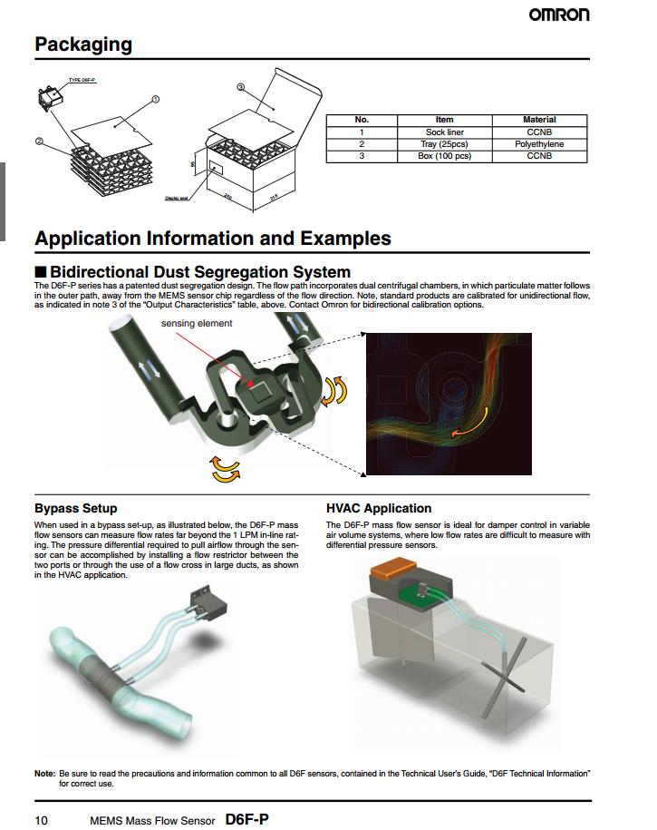
13 MS-TPS: Temperature and Static Air Pressure Sensor The MS-TPS measures static air pressure as well as temperature. TEMPERATURE RANGE: 0 C to +80 C FLOW RANGE: 0 1 LPM REQUIRED VOLTAGE: 12 volts (see notes) ADDITIONAL SENSOR: Omron D6F-P0010A NOTES: The differential pressure for the location is read The device needs 12VDC supplied on pins 7 and 8 of the RJ-45 to operate Page 13
 ADDITIONAL SENSOR: Omron D6F-P0010A NOTES: The inputs are")

14 MS-TPD: Temperature and Differential Air Pressure Sensor The MS-TPD measures differential air pressure as well as temperature. TEMPERATURE RANGE: 0 C to +80 C FLOW RANGE: 0 1 LPM REQUIRED VOLTAGE: 12 volts (see notes) ADDITIONAL SENSOR: Omron D6F-P0010A NOTES: The inputs are redirected by the use of a diverter element, affecting a 180 degree separation of the two inputs The inputs can be extended with flex tubing, allowing for measurements of differential pressure for air handling units, air conditioning systems, and so on The device needs 12VDC supplied on pins 7 and 8 of the RJ-45 to operate Page 14

15 APPENDIX A: Pin Assignments The pin assignments listed below are viewed as looking into either jack on any MS product. The latch is on the bottom side of the jack. Figure 1: Standard EIA/TIA 568 RJ-45 Colors Used with thanks to Lp for public domain image: Pin EIA/TIA 563A 1-Wire Connection Notes Cable Color 1 Orange and White 5 volt return 2 Orange +5 volts 3 Green and White Aux return 4 Blue 1-Wire Data 5 White and Blue 1-Wire Return 6 Green AUX (Switched +5 volts) 7 White and Brown V+ (+12 volts) 8 Brown +12 volts returns Ground Table 1: The wire color and connections for the EIA/TIA 568 RJ-45 cable. Page 15
16 APPENDIX B: MS Type Codes In order to identify every MS product by type, two bytes (00 and 01) are programmed into the product. The first byte determines the product type; the second byte can contain a variant. These bytes can be seen using the 1-Wire Viewer. Bytes 0 (and possibly 1) contain a code from the table below. MultiSensor TM type codes DS2438 User memory byte 0 (&1) Type Hex value Notes MS-T 00 MS-TH 19 original HIH3600 humidity sensor MS-TH 1901 current HIH4000 humidity sensor MS-TV 1A MS-TL 1B MS-TC 1C MS-TW 1D MS-THW 1E MS-TPS 1F MS-TPD 20 MS-TPM 21 Table 2: A table showing the type code for each of the MultiSensor variations How to Read 1-Wire Viewer NOTE: Additional information on using 1-Wire Viewer can be found here. Each device found on the adaptor will be listed under Device List. These devices will be listed by serial number, followed by the product number of any internal sensors found. Select the desired sensor from the list. Depending on the sensor, a number of tabs will appear along the top of the right-hand side of the screen. Select the Memory tab. A field labeled Banks will appear beneath the top tabs. Select User Main Memory from the list provided. Under the box labeled Contents, the MultiSensor s type code will appear in the first available space, as seen in Figure Two below. Page 16

17 FIGURE TWO Figure 2: Under Contents, highlighted by a red box, "1D" is being displayed in the first available space, highlighted by a blue box. This indicates that a MS-TW has been connected. NOTE: For the MS-TH using the current humidity sensor, the type code will be displayed in the first two available spaces, as shown in Figure Three below. Page 17

18 FIGURE THREE Figure 3: The MS-TH's four-digit type code being displayed in the first two available places. The first two digits, "19," are in the first spot and the second two digits, "01," are in the second. Page 18
19 APPENDIX C: Honeywell Humidity Sensor Spec Sheet Page 19
20 Page 20
21 Page 21
22 Page 22
23 Page 23

24 Page 24

25 APPENDIX D: PDV-P8101 Spec Sheet Page 25

26 APPENDIX E: CR Magnetics CR3100 Series Split-Core Current Transformer Spec Sheet Page 26

27 APPENDIX F: Omron D6F-P0010A Spec Sheet Page 27
28 Page 28
29 Page 29
30 Page 30
31 APPENDIX G: Power Some MultiSensors TM can operate on parasitic power, meaning that they use power from the data signal of the 1-Wire bus with a capacitor to sustain them during the zeros. However, unlike most 1-Wire devices, MultiSensors TM have an AUX jumper. The AUX jumper is already set to provide Vcc when shipped from the factory. This jumper connects the Vcc line on the sensor directly to the power source of the serial port (via the master LINK), providing a constant Vcc to the sensor independent of what the line signal is doing. NOTE: If the AUX line of the master (LINK) is being used for another purpose, the jumper on the sensor must be removed. Page 31
32 APPENDIX H: MS-TH VOLTAGE AND ACCURACY The MS-TH uses a supply voltage of 4.7V in perfect conditions instead of 5.0V. This is not due to a design issue. This is due to a protection diode put into the supply for the DS2438 and HIH-4000 used in the MS- TH in order to protect users from miswiring the product. The protection diode creates a supply voltage drop of 0.3V, giving a final supply voltage of 4.7V in perfect conditions. In many conditions, the supply voltage is not perfect. There may be line loss, noise, or a 1-Wire master that has a protection diode. If accuracy is a major concern, it is recommended to test the supply voltage. The HIH-4000 is ratiometric, so the output voltage is a percentage of the supply voltage. The DS2438 is not ratiometric, so it reports a value in the rage of 0 10V based on an internal voltage reference that is not directly related to the supply voltage. Due to this, the result changes when the supply voltage changes. The table below will help users to calculate the output voltage that should be received based on a given RH% and a Vsupply value, as well as the RH% based on a received voltage and a Vsupply value. Alternatively, the equation to calculate %RH from voltage input is as follows: %RRRR = (( (VVVVVVVVVVVV/VVVVVVVVVVVVVV) 0.16))/ Base formula for HIH-4000 Vout=(Vsupply)(0.0062(sensor RH) ) Calculate Output voltage from given RH% Vsupply Volts Input RH 50.00% % RH.0062*RH Add Multiply by Vsupply for voltage reading Volts Calculate %RH assuming 5.0V Vsupply Vsupply Volts Input Voltage Volts Divide by Vsupply 0.47 Subtract Divide by for RH% 50.00% %RH Table 3: A table to help users calculate the output voltage based on a given RH% and a Vsupply value, as well as the RH% based on a received voltage and a Vsupply value. Page 32
33 Index Accuracy ADC... 5 Air Pressure... 12, 13 AUX Casing... 5 Connectors... 5 CR Magnetics... 11, 24 Current Ethernet... 5 Honeywell... 8, 17 Humidity... 8 Light Link , 11 Link , 11 LinkTH... 8, 11 Omron... 13, 25 PDV-P , 23 Pins Power... 5 Spec Sheet... 6, 17, 23, 24, 25 Temperature... 7, 8, 9, 10, 11, 12, 13 Type Codes Voltage... 9, 30 Weather-proof... 5 Page 33
34 Glossary of Terms A Aux jumper Short length of cable used to create a temporary additional connection between terminals D Differential air pressure Pressure measured relative to the pressure in the atmosphere around it. M Master The machine that communicates with the sensor and controls what comes in and out P Parasitic power A device using power contained in data signals of the 1-Wire busses, as well as a capacitor to keep it running during the zeros PCB R Printed circuit board Relative humidity The ratio of water vapor in that air at a certain temperature to the amount of water vapor that the air could hold at that temperature; expressed as a percentage. S Slave V Vcc VDC Sensors that communicate with the master Refers to voltage from a power supply connected to the collector terminal of a bipolar transistor. Volts of direct current Page 34
35 Revision History Date Revision Initials 7/11/16 Updated RJ-45 connection information and diagrams SI Added Appendix H Updated Table of Contents 7/28/16 Updated product photos SI Added revision history Updated Table of Contents Added version number to footer Page 35
The LINK Family Manual Version 1.7 ibuttonlink, LLC 2016 ibuttonlink, LLC 2016
 ibuttonlink, LLC 2016 Page 2 Table of Contents Table of Contents... 3 List of Figures... 5 List of Tables... 6 Introduction... 7 Copyright Notices... 7 Contact Information... 7 Extended Mode Slaves...
ibutton Typer Customer Manual
 ibutton Typer Customer Manual Table of Contents Table of Figures... 2 Introduction... 4 Copyright Notices... 4 Contact Information... 4 What is an ibutton Typer?... 5 Family Features... 5 Molded Body and
Table 1 shows all the different variations of output modules available.
 This application note will show how to configure the LPM409 / LPM616 modular supplies in a series and parallel connection scheme. For a serial connection scheme see Figure 1. For a parallel connection
User's Guide. Model W 3-in-1 Switching DC Power Supply
 User's Guide Model 382260 80W 3-in-1 Switching DC Power Supply Introduction Congratulations on your purchase of the Extech 80W 3-in-1 Switching DC Power Supply. The Model 382260 has three output ranges
Model User Manual Revision E 04/29/99. OEM Gaging System. Part Number R01
 04/29/99 Model 3800 OEM Gaging System User Manual Revision E Part Number 028585-R01 Information in this document is subject to change without notice. No part of this document may be reproduced or transmitted
midon design A 1-Wire Multi-purpose Sensor 1WIO Figure 1 MD2083 As-Shipped August 23, WIO User Guide Version 1.
 A 1-Wire Multi-purpose Sensor 1WIO Figure 1 MD2083 As-Shipped August 23, 2009 1WIO User Guide Version 1.7 Page 1 of 14 1WIO User Guide Version 1.7 1. Table of Contents 1. Table of Contents...2 1.1. List
Reference Manual EPM-PS1. PC/104-Plus Power Supply Module DOC. REV. 4/29/2009
 Reference Manual DOC. REV. 4/29/2009 EPM-PS1 PC/104-Plus Power Supply Module WWW.VERSALOGIC.COM 12100 SW Tualatin Road Tualatin, OR 97062-7341 (503) 747-2261 Fax (971) 224-4708 Contents Copyright 2013
TOXALERT MODEL AIR 2000
 TOXALERT MODEL AIR 2000 NOTE: Toxalert s Model GVU-CO 2 Sensor is the same as the Air2000R. Microprocessor-based, Infrared Environmental CO 2 Sensor OPERATOR S MANUAL TOXALERT TM INTERNATIONAL INC. P.O.
USB-L111. USB-L111 User Manual TPM. Version: V M05. To properly use the product, read this manual thoroughly is necessary.
 USB-L111 USB-L111 User Manual Version: V1.0 2012M05 To properly use the product, read this manual thoroughly is necessary. Part No.: 81-0211100-010 1 Revision History Date Revision Description 2011/8/5
IEI emerge MicroNode Install and Setup Guide. Contents
 IEI emerge MicroNode Install and Setup Guide Contents Connecting power and the network to the MicroNode... 2 Using Power over Ethernet (PoE)... 3 or... 3 Using a 12 VDC power supply... 3 Connecting and
FX-2 Control Board ASY-360-XXX Setup and Configuration Guide
 FX-2 Control Board ASY-360-XXX Setup and Configuration Guide Micro Air Corporation Phone (609) 259-2636 124 Route 526. WWW.Microair.net Allentown NJ 08501 Fax (609) 259-6601 Table of Contents Introduction...
INTEGRATED SYSTEMS AND CONTROL, INC. User s Hardware Manual. PCMNET V 7. xx
 INTEGRATED SYSTEMS AND CONTROL, INC. User s Hardware Manual PCMNET V 7. xx INTEGRATED SYSTEMS AND CONTROLS, INC. PCMNET Users Manual Revised 2/4/2005 2003-2005 Integrated Systems and Control. Inc. PO Box
PAS 9737/AI-SMT ENGINEERING SPECIFICATION
 Document PAS54 Spec Revision C (7/3/8) PAS 9737/AI-SMT ENGINEERING SPECIFICATION 64 CHANNEL, 6 BIT VME ANALOG INPUT CARD PCB Revision D (7/3/8) Additional copies of this manual or other Precision Analog
Model 305e OEM CO 2 concentration sensor
 Model 305e OEM CO 2 concentration sensor preliminary Reference manual DIGITAL CONTROL SYSTEMS 7401 SW Capitol Hwy. Portland, OR 97219 USA 503/246-8110 503/246-6747 (fax) www.dcs-inc.net Scope...3 Introduction...3
0.1 Slow Monitoring and Recording System
 0.1 Slow Monitoring and Recording System A slow monitoring and control system is required to control systematic effects that could impact the experiment, to allow automated scans of parameters such as
HPS-M -2 DIFFERENTIAL PRESSURE TRANSMITTER. Mounting and operating instructions
 DIFFERENTIAL PRESSURE Mounting and operating instructions Table of contents SAFETY AND PRECAUTIONS 3 PRODUCT DESCRIPTION 4 ARTICLE CODES 4 INTENDED AREA OF USE 4 TECHNICAL DATA 4 STANDARDS 5 OPERATIONAL
Hardware User s Manual. Digital Video Motion Detector DVMD1-X
 Hardware User s Manual Digital Video Motion Detector DVMD1-X Version 010 Revision A July, 2004 2395 Kenwood Drive Boulder, CO 80303 (303) 543-0440 TECHNICAL SPECIFICATIONS VENDOR Radiant Inc. http://www.dvmd.com
SmartFan Fusion-4. Speed Control and Alarm for DC Fans CONTROL RESOURCES INCORPORATED. The driving force of motor control & electronics cooling.
 SmartFan Fusion-4 Speed Control and Alarm for DC Fans The driving force of motor control & electronics cooling. P/N FUS300-F DC Controls SmartFan Fusion-4 is a digital fan speed control and alarm that
HA7E-User Manual ASCII RS232 to 1-Wire Host Adapter
 HA7E-User Manual ASCII RS232 to 1-Wire Host Adapter http://www.embeddeddatasystems.com FEATURES ASCII command support for all 1-Wire devices. Powered by RS232 handshake lines. Automatic power up and power
PK2200 Series. Features. C-Programmable Controller. Specifications Board Size Enclosure Size Operating Temp.
 C-Programmable Controller P00 Series The P00 Series of C-programmable controllers is based on the Zilog Z80 microprocessor. The P00 includes digital, serial, and high-current switching interfaces. The
Color Mark Photoelectric Sensor E3S-VS
 Sensing Supply voltage Output 12 to 80 ma, with 1.5 to 4 ma constant current source; 1.2 cm, 5 cm 100 ma, Color Mark Photoelectric Sensor Small Color Mark Sensor With Built-In DC Amplifier Fast, 1 ms maximum
Zone Pressure Touch (ZPT) Sensor - Standard Range
 Sensor - Standard Range") Product Identification BAPI s Touch Pressure Sensor is an accurate, rugged and economical solution for measuring and reporting duct/ building static pressure, room-to-room differential pressure or air
Product Identification BAPI s Touch Pressure Sensor is an accurate, rugged and economical solution for measuring and reporting duct/ building static pressure, room-to-room differential pressure or air
D115 The Fast Optimal Servo Amplifier For Brush, Brushless, Voice Coil Servo Motors
 D115 The Fast Optimal Servo Amplifier For Brush, Brushless, Voice Coil Servo Motors Ron Boe 5/15/2014 This user guide details the servo drives capabilities and physical interfaces. Users will be able to
NEUROLOGIC RESEARCH CORPORATION MODEL 2500
 NEUROLOGIC RESEARCH CORPORATION MODEL 2500 NETWORK HUMISTAT Compact, self-contained dehumidifier controller. 0.5 degrees C accuracy typical. RH sensor is digitally calibrated for 2% accuracy. Open communication
POWERWISE INDAC SETUP MANUAL
 POWERWISE INDAC SETUP MANUAL REVISION: 2.2 INDAC & EMONITOR GATEWAY An installation guide for the PowerWise indac. 2013 PowerWise, Inc. This manual may contain proprietary information about the product
GSV-1A4 M12/2 M12/2. Highlights
 GSV-1A4 M12/2 M12/2 Highlights Input sensitivity: 2mV/V; 4mV/V, 2 mv/v, 1mV/V, 0.5mV/V configurable via jumpers Output signals ±10V AND 12mA+-8mA on 15 pin Sub-D Integrated half and quarter bridge completion
SRI-02 Speech Recognition Interface
 SRI-02 Speech Recognition Interface Data & Construction Booklet The Speech Recognition Interface SRI-02 allows one to use the SR-07 Speech Recognition Circuit to create speech controlled electrical devices.
Manual iaq-engine Indoor Air Quality sensor
 Manual iaq-engine, Version 2.0 May 2011 (all data subject to change without notice) Manual iaq-engine Indoor Air Quality sensor Digital and analog I/O SMD type package Product summary iaq-engine is used
PAS 9732/AI ENGINEERING SPECIFICATION
 Document PAS010 Revision C 8/27/03 PAS 9732/AI ENGINEERING SPECIFICATION 8 CHANNEL, 14 BIT, 3 MHz per CHANNEL VME ANALOG INPUT CARD Revision A (11/18/2000) Additional copies of this manual or other Precision
DS9490R/DS9490B. USB to 1-Wire/iButton Adapters
 AVAILABLE FEATURES High-Speed Mbps Universal Serial Bus (USB) Interface Supports Standard and Overdrive -Wire Communication Slew-Rate-Controlled -Wire Timing and Active Pullup for Improved -Wire Network
Installation Guide. Room Temperature Sensors. Mounting. Location and Cover Removal (All) STE-6011 Only. STE-6010/6013/6015 Only
 STE-6011 Only. STE-6010/6013/6015 Only") Room Temperature Sensors STE-6010/6011/6013/6015 Mounting Location and Cover Removal (All) Install the sensor on an inside wall where it can sense the average room temperature and be away from direct sunlight,
Room Temperature Sensors STE-6010/6011/6013/6015 Mounting Location and Cover Removal (All) Install the sensor on an inside wall where it can sense the average room temperature and be away from direct sunlight,
DL-10. User Manual. RS-485 Remote Temperature and Humidity. English Ver. 1.0, Jul. 2017
 DL-10 User Manual RS-485 Remote Temperature and Humidity English Ver. 1.0, Jul. 2017 WARRANTY All products manufactured by ICP DAS are warranted against defective materials for a period of one year from
NPN output PNP output Cord connection Cord length: 2 m Through-beam 7 m Light-ON. 2 m. (selectable by wiring) Diffuse reflective 0.
 Diffuse reflective 0.") Built-in Amplifier Photoelectric Sensor E3V3 Easy-to-use, Low-cost Photoelectric Sensor Incorporating s that can be clearly seen from a distance. A series of models with an M8 metal junction connector
Built-in Amplifier Photoelectric Sensor E3V3 Easy-to-use, Low-cost Photoelectric Sensor Incorporating s that can be clearly seen from a distance. A series of models with an M8 metal junction connector
Zone Pressure Touch (ZPT) Sensor with Attached Tube (-AT) - Low Pressure Range Unit Installation and Operation Instructions
 Sensor with Attached Tube (-AT) - Low Pressure Range Unit Installation and Operation Instructions") Product Identification BAPI s Touch Low Range Pressure Sensor with Attached Static Pressure Probe is an accurate, rugged and economical solution for measuring and reporting duct/building static pressure,
Product Identification BAPI s Touch Low Range Pressure Sensor with Attached Static Pressure Probe is an accurate, rugged and economical solution for measuring and reporting duct/building static pressure,
-C5RS-LC RS232 EXTENDER
 XTENDEX Series ST-C5RS-LC RS232 EXTENDER Installation and Operation Manual ST-C5RS-LC RS232 Extender Man249 Rev. 10/30/17 TRADEMARK XTENDEX is a registered trademark of Network Technologies Inc in the
Atmos Engineering, Inc. External Specification PN PC104 Air Data Atmodule PN Revision 6.0
 A T M O S E N G I N E E R I N G I N C. Atmos Engineering, Inc External Specification PN 410042 PC104 Air Data Atmodule PN 840025 Revision 6.0 Atmos Engineering, Inc 443 Dearborn Park, Rd Pescadero, CA
KTX REMOTE INSTALLATION INSTRUCTIONS
 KTX REMOTE INSTALLATION INSTRUCTIONS SPECIAL NOTE BOONE CABLE WORKS & ELECTRONICS, INC. 1773-219TH LANE - P.O. BOX 369 READ THIS ENTIRE BOOKLET BOONE, IOWA 50036 USA BEFORE PROCEEDING WITH PHONE (515)
CO-485USB USB to RS-485 CONVERTER TECHNICAL REFERENCE
 TABLE OF CONTENTS CO-485USB USB to CONVERTER TECHNICAL REFERENCE Specifications, Description and Technical Support... page 1 Connection Diagram... page 2 Set-Up & Testing... page 3 & 4 Power Supply Shunts...
IP Speaker System. Users Guide
 ii3-ess IP Speaker System Users Guide ESS User Manual This page intentionally left blank 2 ESS User Manual Table of Contents Overview... 1 Specifications... 2 25/70 Volt Lines... 3 Speaker Configurations...
MODEL A-30 ALTITUDE DIGITIZER OPERATION MANUAL INSTALLATION MANUAL
 LIMITED WARRANTY THIS MODEL A-30 DIGITIZER IS WARRANTED BY ACK TECHNOLOGIES INC. AGAINST DEFECTS IN MATERIALS AND WORKMANSHIP FOR A PERIOD OF THREE YEARS FROM IT S MANUFACTURING DATE. THIS WARRANTY IS
Vorne Industries. 2000S Series Serial Input Alphanumeric Display User's Manual
 Vorne Industries 2000S Series Serial Input Alphanumeric Display User's Manual 1445 Industrial Drive Itasca, IL 60143-1849 Telephone (630) 875-3600 Telefax (630) 875-3609 2000S Series Serial Input Alphanumeric
Mini Photoelectric Sensor
 Mini Photoelectric Sensor High cost-performance Mini Photoelectric Sensor Saves Installation Space and Wiring Effort and Detects Minute Sensing Objects Pin-point beam (1 to 2-mm dia.) makes it possible
Hybrid AC Driver [GCNC-1110]
![Hybrid AC Driver [GCNC-1110]](/thumbs/86/94474371.jpg "Hybrid AC Driver [GCNC-1110]") Page 1 Installation Manual and Datasheet Page 2 Key Features Smooth and quiet operation at all speeds and extremely low motor heating Industrial grade performance for an alternating current servo motor
Page 1 Installation Manual and Datasheet Page 2 Key Features Smooth and quiet operation at all speeds and extremely low motor heating Industrial grade performance for an alternating current servo motor
FX-2 Control Board ASY-360-XXX Setup and Configuration Guide
 FX-2 Control Board ASY-360-XXX Setup and Configuration Guide Micro Air Corporation Phone (609) 259-2636 124 Route 526. WWW.Microair.net Allentown NJ 08501 Fax (609) 259-6601 Table of Contents Introduction...
MICRO SERIES PROCESS DISPLAYS LARGE DIGIT MODELS
 The MICRO SERIES PROCESS DISPLAYS LARGE DIGIT MODELS Mighty-5 DPM MODELS Micro-P & Mighty-1 Mighty-1 Micro-P ELECTRO-NUMERICS, INC. Introduction The Electro-Numerics family of Digital Panel Meters and
MPCR Series DeviceNet Technical Manual TDMPCRDNTM2-0EN 01/08 Subject to change without notice
 MPCR Series DeviceNet Technical Manual Table of Contents MPCR Series Introduction... 3 Product Overview... 3 About DeviceNet... 4 Overview... 4 MPCR DeviceNet Features... 4 Cabling and Drop Line Lengths
Product description for ED1600 generic Sigfox Module
 Product description for ED1600 generic Sigfox Module The ED1600 Sigfox Module is mainly developed for container tracking purposes. To avoid the development of many different types of modules and just as
Mounting DIGITAL DISPLAY
 Mounting The Class digital display mounts in a. by. cutout. Overall area necessary for installation is. by.. Two 0.0 diameter holes are provided for mounting screws..0".0..0.900 Ø 0.0" () HOLES."." DIGITAL
BalloonSat Sensor Array
 BalloonSat Sensor Array The PICAXE-08M2 in the BalloonSat flight computer is a digital device. Being digital, it functions best with a series of on and off voltages and does not interact very well with
Environdata FA ma Converter Guide
 FA12 4 20 ma Converter Guide REV 14 th July 2015 Material in this Handbook is copyright. All rights reserved by the publishers. Weather Stations Pty. Ltd., 42-44 Percy Street, Warwick, Queensland, AUSTRALIA,
7I74 MANUAL 8 CHANNEL RS-422 INTERFACE
 7I74 MANUAL 8 CHANNEL RS-422 INTERFACE V1.2 This page intentionally almost blank Table of Contents GENERAL.......................................................... 1 DESCRIPTION.................................................
Light & Sound Control Module
 Light & Sound Control Module Operation and Installation Manual G-Scale Graphics 5860 Crooked Stick Dr. Windsor, CO 80550 970-581-3567 GScaleGraphics@comcast.net www.gscalegraphics.net Revision 55: C: Updated
E3X-NA. Adjuster type standard that is the culmination of true ease and simplicity. Super Manual Fiber Amplifier. Features
 Super Manual Fiber Amplifier Adjuster type standard that is the culmination of true ease and simplicity Features Self-explanatory LED bar displays of light levels The previous manual type used the stability
LAUREL. Laureate Digital Panel Meter for Process and Ratiometric Signals ELECTRONICS, INC. Features. Description
 LAUREL ELECTRONICS, INC. Laureate Digital Panel Meter for Process and Ratiometric Signals Features Reads process signals from ±200 mv to ±600V or ±2 ma to ±5A full scale Ratiometric mode for bridges and
TECHNICAL PRODUCT DATASHEET
 FORM-ENG-0018 REV A 06-02-03 ISO 9001 CERTIFIED Phone: (352) 629-5020 or 800-533-3569 Fax: (352)-629-2902 SUITABLE FOR EXTERNAL DISTRIBUTION TECHNICAL PRODUCT DATASHEET ES-Key Climate Control Module P/N
Option 2. Nil. Note 1) Option 1. Note With waterproof seal and mounting screw. With waterproof seal and mounting screw. 48 conversion adapter
 Option 1. Note With waterproof seal and mounting screw. With waterproof seal and mounting screw. 48 conversion adapter") Series 0-PSE00 RoHS Remote Type Multi-Channel Digital Pressure Sensor Controller How to Order Clean series 0 PSE0 0 M Input/Output specifications 0 NPN 5 outputs + Auto shift input PNP 5 outputs + Auto
Series 0-PSE00 RoHS Remote Type Multi-Channel Digital Pressure Sensor Controller How to Order Clean series 0 PSE0 0 M Input/Output specifications 0 NPN 5 outputs + Auto shift input PNP 5 outputs + Auto
KPW-T2P25. PoE Splitter. Industrial IEEE 802.3at High Power. User s Manual -1- DOC
 KPW-T2P25 Industrial IEEE 802.3at High Power PoE Splitter User s Manual DOC.121011-1- (C) 2012 KTI Networks Inc. All rights reserved. No part of this documentation may be reproduced in any form or by any
Digital Lighting Systems, Inc.
 , Inc. PD402-DMX Four Channel Dimmer and Switch Packs 4 x 2.5 Amps @ 6VDC to 24 VDC DMX52 compatible DMX52 4 x 2.5 Amps Dimmer Pack C UL US LISTED Digital Lighting Systems, Inc. USER'S MANUAL User's Manual
FEATURES. APPLICATIONS Machine Vision Embedded Instrumentation Motion Control Traffic Monitoring Security
 FEATURES High-performance CMOSIS sensors - Sensitivity: 5.56 V/lux.s - Dynamic range: 60 db - Dark Noise: 8.6 e - - High speed: 95* fps - 8M Pixel: 3360(H) x 2496(V) - Monochrome / Color - Global Shutter
Quick Start Guide. SEB-710 I/O Expansion board. Introduction
 SEB-710 I/O Expansion board Revision 1.0 - (March, 2011) Saflec Systems (Pty) Ltd Quick Start Guide Introduction The SEB-710 is an I/O expansion device for additional inputs and outputs. It has eight relay
and/or b. an optional internal Iridium satellite modem.
 Appendix D Manual for Data Logger/Control Unit D.1. Introduction and Specifications D.1.1. Q DL 2100 Data logger Platform The Q DL 2100 data logger platform consists of: 1. A microcontroller containing
Industrial 3-Port Fast Ethernet Media Converter Switches
 Industrial 3-Port Fast Ethernet Media Converter Switches KSD-103-A series KSD-103-B series Installation Guide DOC.081111 1/20 (C) 2008 KTI Networks Inc. All rights reserved. No part of this documentation
RibEye Multi-Point Deflection Measurement System 3-Axis Version for the SIDIIs ATD Hardware Manual for Model January 2010
 USER S MANUAL RibEye Multi-Point Deflection Measurement System 3-Axis Version for the SIDIIs ATD Hardware Manual for Model 7715 15 January 2010 Boxboro Systems, LLC 978-257-2219 www.boxborosystems.com
STYLE 3600 SWITCH INTERFACE TRANSMITTER INSTALLATION AND OPERATING INSTRUCTIONS
 STYLE 3600 SWITCH INTERFACE TRANSMITTER INSTALLATION AND OPERATING INSTRUCTIONS The following is intended to provide the basic instructions for installation and operation of the Switch Interface Transmitter
DMX Decoder-Studio 4-Channel
 DMX Decoder-Studio 4-Channel Part numbers: DMX-4-5000-3, DMX-4-5000-5 11235 West Bernardo Court, Suite 102 San Diego, CA 92127 888-880-1880 Fax: 707-281-0567 EnvironmentalLights.com The DMX-4-5000 is a
Sierra Radio Systems. Digital Compass. Reference Manual. Version 1.0
 Sierra Radio Systems Digital Compass Reference Manual Version 1.0 Contents Digital compass board RS485 power injector For more information, go to the Sierra Radio Systems web site at www.sierraradio.net
RTD-W Installation Instructions
 RTD-W Installation Instructions 0V +V POWER 15-24VDC 0V S1 S2 S3 0V S4 S5 S6 English RTD-W Installation Instructions 100.00 RTD-W Control Interface realtime Control Systems 24VAC/30VDC, 1A REMC P1 P2 RS485
EPT-200TMP-TS-U2 TMP102 Temperature Sensor Docking Board Data Sheet
 EPT-2TMP-TS-U2 TMP12 Temperature Sensor Docking Board Data Sheet This docking board is based on the TMP12 Temperature Sensor chip from Texas Instruments. It can measure the ambient temperature between
Evaluates: DS28E80. DS28E80 Evaluation System. General Description. Benefits and Features. EV Kit Contents
 General Description The DS28E80 evaluation system (EV system) consists of a single evaluation kit (EV kit) that includes a package of five DS28E80 devices in a 6-pin TDFN package, a DS9120Q+ socket board
Computer Temperature Interface model CTI-2. Description. Installation. Control Module
 Description The Sine Systems model CTI-2 Computer-Temperature Interface allows a computer to monitor the outside air temperature. It consists of a 2.75 x 3 x 0.75 control module with 8 screw-terminal connections.
DWYER INSTRUMENTS, INC. Series AVUL Air Velocity Transmitter. Specifications - Installation and Operating Instructions.
 Series AVUL Air Velocity Transmitter Specifications - Installation and Operating Instructions Bulletin P-AVUL 3-49/64 [95.71] 2-43/64 [67.92] 1/2 NPS 3-3/16 [80.81] 1-19/32 [40.59] 31/32 24.58 3-33/64
2U Congestion Alert Rack Insert for UK
 2U Congestion Alert Rack Insert for UK 2U Congestion Alert Rack Insert for UK The 2U congestion alert rack insert comes fully assembled, wired and ready to be installed in a rack. The rack provides communications,
AC-43 Accelerometer. User Manual
 AC-43 Accelerometer Manual Page 1 AC-43 Accelerometer User Manual Company: Author: Checked: Approved: Distribution: GeoSIG Ltd Wiesenstrasse 39, 8952 Schlieren, Switzerland, Tel: +41 44 810 21 50, Fax:
Digital Keypad Introduction
 K2 Digital Keypad Introduction The K02 uses the latest microprocessor technology to operate door strikes and security systems that require a momentary (timed) or latching dry contact closure. All programming
Connecting igaging DigiMAG Scales to the Caliper2PC Interface A step by step Guide
 What is an igaging DigiMAG Scale? The igaging DigiMAG are digital linear scales that are easily connectable to the Caliper2PC interface. They consist of two parts, the encoder and the readout unit. The
MICRO BURN IN PRODUCTS LISTED IN MODEL NUMBER ORDER FOLLOWED BY A BRIEF DESCRIPTION
 MICRO BURN IN PRODUCTS LISTED IN MODEL NUMBER ORDER FOLLOWED BY A BRIEF DESCRIPTION MODEL 102P 102R DESCRIPTION Floor Stand (Plane) Floor Stand (Modified) HTRB Burn-In System (diode) Component Burn-In
JR3 EXTERNAL SENSOR ELECTRONICS WITH SERIAL DATA OUTPUT. JR3, Inc. 22 Harter Ave. Woodland, CA 95776
 JR3 EXTERNAL SENSOR ELECTRONICS WITH SERIAL DATA OUTPUT JR3, Inc. 22 Harter Ave. Woodland, CA 95776 5963B 13 October, 2003 TABLE OF CONTENTS CHAPTER 1 OVERVIEW General...1-1 Sensor...1-1 Electronic System...1-1
Fiber optic converter audio and CAN TA OPERATION MANUAL
 Fiber optic converter audio and CAN TA-110.1 IOA110-1 March 2009 LANEX S.A., Technical support: tel. ul.ceramiczna 8, 20-150 Lublin tel. +48 81 443 96 36 Contents 1. General Characteristics.... 5 1.1.
Linear Actuator Reference Manual
 MP-21 S e r i e s Linear Actuator MP-21 Linear Actuator Rev 3.04 MICRONIX USA, LLC 15375 Barranca Parkway, E-106 Irvine, CA 92618 Tel: 949-480-0538 Fax: 949-480-0538 Email: info@micronixusa.com http://micronixusa.com
VertX. V100, V200 and V300. Installation Guide Barranca Parkway Irvine, CA USA. November Rev A.1
 15370 Barranca Parkway Irvine, CA 92618 USA VertX V100, V200 and V300 Installation Guide November 2011 6080-930 Rev A.1. Contents Introduction... 3 Parts List... 3 Product Specifications... 3 Cable Specifications...
Control & Interface Electronics. CCD Sensor
 FEATURES High Performance Scientific Camera Hamamatsu S10141 Sensors 1024 x 122 to 2048 x 506 active pixels 12 µm x 12 µm pixel size Integrated TE Cooling -15 C from 20 C ambient Hermetically sealed Temperature
CRC220 and CRC221 INSTALLATION GUIDE. REF No.: DOC0014 ISSUE: 09
 CRC220 and CRC221 INSTALLATION GUIDE REF No.: DOC0014 ISSUE: 09 30th July 2015 2 Contents CRC220 & CRC221 INSTALLATION GUIDE 1. Scope 1-1 2. Introduction 2-1 2.1 Features 2-1 2.1.1. PCB Features 2-1 2.1.2.
Rugged MediaConverter
 Rugged MediaConverter Installation Guide RuggedCom Inc. 30 Whitmore Road, Woodbridge, Ontario Canada L4L 7Z4 Web: http://www.ruggedcom.com/ Tel: (905) 856-5288 Fax: (905) 856-1995 Toll Free: (888) 264-0006
PADPULS2 M-BUS Pulse Input Modules
 Product sheet MT8.23 Meter Type PADPULS2 PADPULS2 M-BUS Pulse Input Modules The M-PADPULS series of devices connects meters with contact output to the M-Bus system. This is a simple and flexible solution
Communication module to connect M-bus devices to POL6xx.xxx controllers.
 s 3 936 Climatix TM Climatix communication M-Bus module POL907.00/xxx Communication module to connect M-bus devices to POL6xx.xxx controllers. The POL907.00/xxx communication module offers the following
Energy Management System. Operation and Installation Manual
 Energy Management System Operation and Installation Manual AA Portable Power Corp 825 S 19 TH Street, Richmond, CA 94804 www.batteryspace.com Table of Contents 1 Introduction 3 2. Packing List 5 3. Specifications
User s Manual Hub444. Motion Control Network Hub
 8/23/02 JK User s Manual Motion Control Network Hub Applied Motion Products, Inc. 404 Westridge Drive Watsonville, CA 95076 Tel (831) 761-6555 (800) 525-1609 Fax (831) 761-6544 motors drives controls -2-
Zone Pressure Touch Sensor - Standard Range
 Overview The Zone Pressure Touch (ZPT) Sensor is an accurate, rugged and economical solution for measuring and reporting duct/ building static pressure, room-to-room differential pressure or air velocities/volumes.
EnerSure Installation Guide
 EnerSure Installation Guide Danger!!! The electrical components of this system may contain voltage and /or amperage sufficient to injure or kill. Installation is only to be performed by a licensed, bonded
16-Channel 16-Bit PMC Analog I/O Board
 16-Channel 16-Bit PMC Analog I/O Board With 8 Input Channels, 8 Output Channels, and Autocalibration Eight 16-Bit Analog Output Channels with 16-Bit D/A Converter per Channel Eight 16-Bit Analog Input
Preamplifiers for Amptek X-Ray Detectors. OEM Preamplifiers for Amptek X-Ray Detectors
 Preamplifiers for Amptek X-Ray Detectors OEM Preamplifiers for Amptek X-Ray Detectors PA-210 PA-230 NOTE: If you are using the Amptek DP5/PC5 with the PA-210/PA-230 you do not need any of the information
14-Bit, 4-Channel, 50MSPS/Channel PMC Analog Input Board
 PMC66-14HSAI4 14-Bit, 4-Channel, 50MSPS/Channel PMC Analog Input Board With 66MHz PCI Compatibility, Multiple Ranges, and Data Packing Available also in PCI, cpci and PC104-Plus form factors as: PCI66-14HSAI4:
7I44 MANUAL 8 CHANNEL RS-422 INTERFACE
 7I44 MANUAL 8 CHANNEL RS-422 INTERFACE V1.1 This page intentionally almost blank Table of Contents GENERAL.......................................................... 1 DESCRIPTION.................................................
TRITIUM COLLECTION SYSTEMS
 F&J SPECIALTY PRODUCTS, INC. The Nucleus of Quality Air Monitoring Programs TRITIUM COLLECTION SYSTEMS 100 120 VAC KH3-200 MRB200H3 MRB200H3-60ML MRB500H3 TCS-3000-BL TCS-5000-BLDC Rev: 13 June 2018 Tel:
SmartFan Vortex. I2C Speed Control for 12 VDC Fans CONTROL RESOURCES INCORPORATED. The driving force of motor control & electronics cooling.
 The driving force of motor control & electronics cooling. SmartFan Vortex I2C Speed Control for 12 VDC Fans DC Controls P/N VOR5I400F SmartFan Vortex is an I2C fan speed control and alarm designed for
TOKISTAR LIGHTING INSTRUCTION MANUAL 24 VDC or 24 VAC
 TokiLux TM Series TOKISTAR LIGHTING INSTRUCTION MANUAL 24 VDC or 24 VAC General Description Tokistar's TokiLux Series may be operated at 24 VDC or 24 VAC. Light Bars are installed end-to-end within the
HWg-STE HWg-STE PoE MANUAL
 HWg-STE HWg-STE PoE MANUAL HWg-STE connections LED indicators Green: Power & Mode Yellow: Link & Activity SENSORS S1 and S2 ports for connecting temperature or humidity sensors. - Max. distance with 1
Industrial Ultra Power over Ethernet Splitter IPOE-171S
 Industrial Ultra Power over Ethernet Splitter IPOE-171S User s Manual Table of Contents 1. Package Contents... 3 2. Product Features... 4 3. Product Specifications... 5 4. Hardware Introduction... 8 4.1
LLIA90 LED ARRAY 90 LED Array Illuminator. LLIA90 LED Illuminator Array
 LLIA90 LED Illuminator Array The LLIA90 is a high-quality and high-performance multi-purpose LED illuminator array. It has a built-in regulator and a photocell control circuit for automatic LED array on/off
CS4141 IDL Notes. I. Quick Overview of IDL Prototyping Unit
 CS4141 IDL Notes IDL-800 Prototyping System The IDL-800 logic panels are powerful tools for any logic designer. They enable a wide range of IC s to be used in a breadboard experiment. I. Quick Overview