ULTRA 3 INSTRUCTION MANUAL
|
|
|
- Gary McGee
- 5 years ago
- Views:
Transcription


1 ULTRA 3 INSTRUCTION MANUAL
2
3 ULTRA 3 (THIRD EDITION) February 2009 Part Number M P COPYRIGHT Pulsar Process Measurement Limited, All rights reserved. No part of this publication may be reproduced, transmitted, transcribed, stored in a retrieval system, or translated into any language in any form without the written permission of Pulsar Process Measurement Limited. WARRANTY AND LIABILITY Pulsar Process Measurement Limited guarantee for a period of 2 years from the date of delivery that it will either exchange or repair any part of this product returned to Pulsar Process Measurement Limited if it is found to be defective in material or workmanship, subject to the defect not being due to unfair wear and tear, misuse, modification or alteration, accident, misapplication or negligence. DISCLAIMER Pulsar Process Measurement Limited gives nor implies any process guarantee for the this product, and shall have no liability in respect of any loss, injury or damage whatsoever arising out of the application or use of any product or circuit described herein. Every effort has been made to ensure accuracy of this documentation, but Pulsar Process Measurement Limited cannot be held liable for any errors. Pulsar Process Measurement Limited operates a policy of constant development and improvement and reserves the right to amend technical details as necessary. TECHNICAL ENQUIRIES Please contact Pulsar Process Measurement Limited for technical support. COMMENTS AND SUGGESTIONS If you have any comments or suggestions about this product, then please contact: Pulsar Process Measurement Limited Cardinal Building Enigma Commercial Centre Sandy s Road Malvern Worcestershire WR14 1JJ United Kingdom Tel: (International ) Fax: (International ) Web Site: info@pulsar-pm.com (general information) support@ pulsar-pm.com (product support)
4
5 Contents Chapter 1 Start Here...1 About this Manual...1 About the Ultra Functional Description...3 How to use this Manual...4 Product Specification...5 Chapter 2 Installation...7 Power Supply Requirements...7 Location...7 Dimensions...8 Wall Mount...8 Fascia Mount...10 Rack and Panel...12 Terminal Connection Details...14 Wall Mount...14 Fascia Mount...14 Rack and Panel...15 Voltage Selector and Fuse Location...17 Wall mount...17 Fascia mount...17 Rack and Panel mount...18 Preparation for Operation...20 Maintenance...20 Chapter 3 How To Use Your Ultra Operating the Controls...21 Display...21 Run Mode...22 Program Mode...23 How to Access Program Mode...23 Wall and Fascia mount...23 Rack and Panel...23 Test Mode...29 Using the RS232 Serial Interface...30 Parameter Defaults...32 Factory Defaults...32 Chapter 4 Ultra Wizard...33 Ultra Wizard Menu...33 Lev/Vol...34 Level Star Pump...34 Vantage Flow...35 Flow Oracle Chapter 5 Level / Volume...37 Quick Setup Menu...39 Example 1 Level Monitoring with Alarms...43 Example 2 Level Monitoring and Control (up or down)...45 Example 3 Volume Application...47 Menu System and Parameter Guide...50
6 Top Level Menu...50 Application Menu...51 Relays Menu...52 Data Logs Menu...53 Volume Menu...54 Display Menu...55 ma Output Menu...55 Compensation Menu...56 Stability Menu...56 Echo Processing Menu...57 System Menu...58 Device Comm Menu...59 Test Menu...60 Chapter 6 Pump...61 Quick Setup Menu...63 Example 1 Level Monitoring with Alarms...66 Example 2 Sump Control (pump down)...68 Example 3 Reservoir Control (pump up)...70 Menu System and Parameter Guide...72 Top Level Menu...72 Application Menu...73 Relays Menu...74 Data Logs Menu...75 Display Menu...76 ma Output Menu...76 Compensation Menu...77 Stability Menu...77 Echo Processing Menu...78 System Menu...79 Device Comm Menu...80 Test Menu...81 Chapter 7 Flow...83 Quick Setup Menu...86 Exponential Devices...90 Point of Measurement...91 Calculations...93 Example 1 V Notch Weir...95 BS3680 Flumes...97 Point of Measurement...97 Calculations...98 Example 2 BS3680 U-Throated Flume BS3680 Thin Plate Weirs Point of Measurement Calculations Example 3 BS3680 Rectangular Weir BS3680 Rectangular Broad Crested Weir Point of Measurement Calculations Special Devices Point of Measurement Calculations Universal Calculations Point of Measurement Calculations Menu System and Parameter Guide...111
7 Top Level Menu Application Menu Relays Menu Data Logs Menu OCM Display Menu ma Output Menu Compensation Menu Stability Menu Echo Processing Menu System Menu Device Comm Menu Test Menu Chapter 8 Parameter Listing and Descriptions Application Parameters Operation Dimensions Relay Parameters Alarms General Control Pumps Control Miscellaneous Common Parameters Data Log Parameters Totaliser Audits Temperature Volume Conversion Breakpoints Tables OCM Parameters PMD Setup Dimensions Calculations Breakpoints Tables Average Flow Display Parameters Options Failsafe Auxiliary Totaliser Bargraph ma Output Parameters Range Operation Setpoint Limits Trim Failsafe Allocation Compensation Parameters Offset Temperature Velocity...166
8 Stability Parameters Damping Indicator Rate Filters Echo Processing Parameters Transducer 1 Status System Parameters Passcode Backup System Information Date & Time LED Colour Watchdog Daylight Saving Time Device Comm RS232 Set Up RS 485 Set Up Remote Alarm Test Parameters Simulation Hardware Chapter 9 Troubleshooting Parameter Record...187
9 Chapter 1 Start Here Congratulations on your purchase of a Pulsar Ultra 3. This quality system has been developed over many years and represents the latest in high technology ultrasonic level measurement and control. It has been designed to give you years of trouble free performance, and a few minutes spent reading this operating manual will ensure that your installation is as simple as possible. About this Manual It is important that this manual is referred to for correct installation and operation. There are various parts of the manual that offer additional help or information as shown. Tips TIP At various parts of this manual you will find tips to help you. Additional Information Additional Information At various parts of the manual, you will find sections like this that explain specific things in more detail. References See Also References to other parts of the manual Page 1

10 About the Ultra 3 Ultra 3 is three units in one. Ultra 3 is a brand new concept in ultrasonic level measurement. Within its memory are all the functions and settings of three different and completely separate ultrasonic devices. Page 2 The Ultra 3 does not offer a multiple range of functions blended together which lead to complicated calibration and a compromise to the specification, Ultra 3 is the first ever system to offer the ability to dedicate the functionality of the unit to any of three specific duties i.e. level or volume measurement, pump control, or flow measurement. The benefits are many but most importantly the unit provides: 1. A most versatile system which is quickly configurable to offer anyone three separate functions within seconds. Ideal for simplicity of purchase and off the shelf spares. 2. A totally dedicated device with the ability to perform all aspects of the task required i.e. no compromise in specification. 3. Easy to set up using the unique Quick Set Up Menu. To calibrate, first set the Ultra Wizard for the desired task, and then refer to the relevant chapter in this manual that relates to your application: Chapter 5 for Level or Volume, Chapter 6 for Pump Control Chapter 7 for Flow
11 Functional Description Ultra 3 sends a transmit pulse to the transducer, which emits an ultrasonic pulse perpendicular to the transducer face, and the returned echo is sent back to the Ultra 3. The time taken to receive the echo is measured and the distance from the transducer face to the surface being monitored is calculated. Ultra 3 can measure from zero to 40m from the face of the transducer to the surface being monitored, dependent on the application chosen and transducer used. The relays can be programmed to activate alarms, pump starters, or other control equipment. There is an isolated 4-20 ma output that can be connected to a recorder or PLC, to monitor, depending on application chosen, level, space, distance, OCM head, OCM flow or volume, independently from that shown on the display. There is an RS232 port, so that the Ultra 3 can be operated remotely by a PC or other equipment. Ultra 3 can be programmed either by the built-in keypad (standard on all wall and fascia units), or by PC via the RS 232 Serial Interface (optional). The optional rack and panel mounted units are programmed with the Remote Communicator, and one Communicator can program many Pulsar Ultra 3 units. All parameters are stored in non-volatile memory, so are retained in the event of power interruption. A second backup copy of all parameters can also be retained in the Ultra 3 memory, in case an alternative set of parameters needs to be stored. Three user definable control relays with individual setpoints and intelligent performance logging software features ensure maximum control versatility. The system utilises the unique DATEM software (Digital Adaptive Tracking of Echo Movement). This is a proven digital mapping technique developed especially for the Pulsar Ultra range, which gives the system unequalled ability when identifying the true target level in the face of competing echoes from pipes, pumps or other obstructions. Coupled with the powerful, long-range abilities of the all new db transducer range, the Ultra 3 lives up to its reputation as the most reliable ultrasonic level measurement system available. The Pulsar Ultra 3 ultrasonic level controller has been designed to provide maintenance-free fit and forget performance. Page 3
12 How to use this Manual 1. Read the installation and operating instructions contained in, Chapters 2 and 3, carefully, they are applicable in every use of this product. 2. Decide which task you wish your Ultra 3 to perform for you and then configure the unit using Ultra Wizard as described in Chapter Move directly to the appropriate chapter of this manual, as listed below, for details on how to program Ultra 3 using the Quick Set Up Menu. Chapter Chapter 5 Level/Volume Chapter 6 Pump Chapter 7 Flow Duty / Task Measurement of Level or Volume Control of Pumps Measurement of Open Channel Flow Page 4
13 Product Specification Physical Wall Mount Outside dimensions Weight Enclosure material/description 188 x 160 x 107 mm Nominal 1 kg Polycarbonate, flame resistant to UL91 Cable entry detail 8 cable entry knock outs, 1 x M16, 3 x M20 underside, 4 x 18mm dia (PG11) at rear Fascia Mount Outside dimensions 200 x 112 x 108 Weight Nominal 1.3kg Enclosure material/description Stainless Steel back, Polycarbonate UL94-V0 front and bezel Rack mount 10HP x 160 mm deep x 3U (128.5 mm) high Panel mount 72 mm wide x 144 mm high x 176 deep Transducer cable extensions Maximum separation 2-core screened 1000 m Environmental IP Rating (Wall) IP65 IP Rating (Fascia) IP64 Optional IP rated panel mount IP54 Max. & min. temperature (electronics) -20 ºC to +50 ºC Flammable atmosphere approval Safe area: compatible with approved db transducers (see transducer spec' sheet) CE approval EMC approval to BS EN :1992 for emissions and BS EN :1995 for immunity, and to BS EN :1993 for low voltage directive Performance Accuracy Resolution Max. range Min. range Rate response 0.25% of the measured range or 6 mm (whichever is greater) 0.1% of the measured range or 2 mm (whichever is greater) Dependant on application and transducer (maximum 40m db40 dependant on application) Dependent on application and transducer (minimum zero db Mach 3) fully adjustable Page 5
14 Echo Processing Description Outputs Analogue output Digital output Volt free contacts, number and rating Display Programming On-board programming PC programming Remote programming (Rack and Panel option only) Programming security Programmed data integrity Supply Power supply Fuses Remote Communicator Batteries DATEM (Digital Adaptive Tracking of Echo Movement) Isolated (floating) output (to 150V) of 4-20 ma or 0-20 ma into 500Ω (user programmable and adjustable) 0.1% resolution Full Duplex RS232 3 form "C" (SPDT) rated at 5A at 240V AC 6 digits plus 12 character text, plus bargraph with direction indicators, remote communicator identifier, and program/run/test mode indicators By integral keypad via RS232 By optional infra red communicator Via passcode (user selectable and adjustable) Via non-volatile RAM, plus backup 115V ac + 5% / -10% 50/60 Hz, 230V ac + 5% / -10% 50/60 Hz, dc 18-30V 10W maximum power (typically 6W) 100 ma at VAC 200 ma at VAC 2 x AA alkaline batteries. Do not use NiCads. Pulsar Process Measurement Limited operates a policy of constant development and improvement and reserve the right to amend technical details as necessary. Page 6

15 Chapter 2 Installation Power Supply Requirements Ultra 3 can operate from AC supply or from a DC battery. The AC is either V 50/60Hz or V 50/60Hz, depending on the position of the selector switch. The DC is 18-30V. In all cases the Ultra 3 will typically consume 6W of power, with a maximum of 10W. Location All electronic products are susceptible to electrostatic shock, so follow proper grounding procedures during installation. Ultra 3 must be mounted in a non-hazardous (safe) area, and the transducer fitted in the hazardous area. Page 7
16 When choosing a location to mount the enclosure, bear in mind the following: Dimensions Ensure that the Ultra 3 is installed in a Safe, non-hazardous, area. For a clear view of the LCD display it is recommended that it is mounted at eye level. The mounting surface is vibration-free. The ambient temperature is between -20ºC and 50ºC. There should be no high voltage cables or inverters close by. Wall Mount The dimensions of the wall fixing holes are as shown below. 117 mm 151 mm Ultra 3 should be mounted by drilling three holes suitable for size 8 screws (length to suit your application), and fixing the top screw in place. Hang the unit on this and fix the two remaining screws by removing the terminals access cover to access the pre-drilled holes. Page 8
17 The full dimensions of the enclosure are as shown below. Page 9
18 Cable Entry There are 4 cable gland knock-outs on the base of the wall mount Ultra 3 (1 x M16, 3 x M20) and 4 on the rear (4 x 18mm dia (PG11). Select which ones you wish to use, and remove them by using a circular cutter, such as a tank cutter. Take care not to damage the circuit board inside whilst undertaking this. Do not use a hammer, as this may cause damage to the enclosure. It is recommended that you use suitable cable glands to ensure that the ingress rating is maintained. Fascia Mount The Fascia mount Ultra 3 should be installed by cutting a hole in the panel as detailed below. Page 10
19 The full dimensions of the Fascia mount enclosure are as shown below. Page 11
20 Rack and Panel The Ultra 3 rack mount unit is a standard 10HP plug in unit, for a standard 84HP (19 ), 160 mm sub rack unit. The connector that is supplied with the rack unit should first be fitted to the back of the sub rack, so that when the rack unit is inserted into the rack, it connects correctly. To install the unit into the sub rack, slide the Ultra 3 into the rack and secure by tightening the four captivated screw that are in the faceplate. The panel mount unit should be installed by cutting a hole of size DIN x mm in the panel, then insert the Ultra 3 enclosure through the hole, and tighten the fixing screws from the rear. Make sure you leave sufficient room for the cables behind the enclosure (a depth of at least 225 mm behind the panel should suffice). All electronic products are susceptible to electrostatic shock, so follow proper grounding procedures during installation. Dimensions of the rack enclosure are as shown below: Page 12
21 Dimensions of the panel enclosure are as shown below: Page 13
22 Terminal Connection Details Wall Mount The terminal strip is as detailed below. There is also a wiring diagram inside the terminals access cover. Fascia Mount The terminal details are as illustrated below. Page 14
23 Rack and Panel The terminal strip is as detailed below. There is also a wiring diagram on the side of each unit. Page 15
24 Terminal Connections Power Ultra 3 can operate from mains AC and automatically from DC or battery backup in the event of power failure, or can be operated permanently from DC or batteries. Transducer The transducer should be installed, and connected, in accordance with the installation instructions contained in the Transducer User Guide. The entire range of, standard db transducers are certified for use in hazardous areas and different models, for each, are available for use in Zone 1 or Zone 0. Wire the transducer to the Ultra 3 s transducer terminals, terminal numbers will depend on the unit type, as follows: Unit Type Terminal Connection Details White Black Signal 0 volts Red Power Green Screen Wall Mount Fascia Mount Rack or Panel c2 c4 c6 c6 Page 16 When using 2 core screened extension cable, the Black and Green wires of the transducer should be connected to the screen of the extension cable. For Zone 1 applications a transducer certified to Sira 02ATEX5104X is used, and must be supplied via a 4000A breaking fuse, which is fitted as standard to the Ultra 3. For Zone 0 a transducer certified to Sira 02ATEX2103X is used, which must be connected to the Ultra 3 controller via an external Zener barrier. See transducer label for certification details. Relay Outputs The three relays can be programmed for a variety of alarms, pump control, or other process functions. The relay contacts are all rated at 5A at 240V AC. All connections should be such that the short circuit capacity of the circuits to which they are connected, is limited by fuses rated so that they do not exceed the relay rating.
25 Current Output This is an isolated (floating) ma output (to 150 V), of 4-20mA or 0-20mA, and the load should not exceed 500 Ω. RS232 Serial Interface If required, you can connect to the serial interface, to operate your Ultra 3 remotely. Voltage Selector and Fuse Location Wall mount The voltage selector switch and mains fuse is located, inside the terminal compartment, to the left of the mains terminals, as illustrated below. Fascia mount The voltage selector switch and mains fuse is located under the removable cover at the bottom of the unit, as illustrated below. Page 17
26 Rack and Panel mount The voltage selector switch and mains fuse is situated on the inside of the bottom PCB, as illustrated below, and can be accessed from the lower side of the rack unit. Page 18
27 Important Information The rear metalcase of the fascia unit must be connected to earth via the earthing stud located on the rear of the unit, see drawing above, using wiring to meet local requirements. Before applying AC power (mains), make sure you have correctly selected the voltage selector switch, as detailed in the preceding pages. Please note that all units are supplied set to 230 volts AC for safety reasons. Never operate the Ultra 3 with terminal access exposed. An external switch or circuit breaker should be installed near to the Ultra 3 to allow the supply to be removed during installation and maintenance. In addition, the relay contacts should also have a means of isolating them from the Ultra 3. Interconnecting cables must be adequately insulated for IEC 664 Category II installations. Strip back 30 mm of the outer insulation of the cable. Strip 5 mm of insulation from the end of each conductor. Twist all exposed strands of the conductor together. Insert the stripped conductor into the terminal block as far as it will go and tighten the terminal block screw. Ensure that all strands are firmly clamped in the terminal block and that there is no excess bare conductor showing, and no stray strands. DON T FORGET Make sure you move the voltage selector switch to the correct position for your supply. Important Information If the equipment is installed or used in a manner not specified in this manual, then the protection provided by the equipment may be impaired. Page 19
28 Preparation for Operation Before switching on, check the following: Maintenance Ultra 3 is mounted correctly and is in a safe area. The power supply is correctly installed. The voltage selector switch is in the correct position. The relays are connected correctly. There are no user serviceable parts inside Ultra 3, except the mains fuse. If you experience any problems with the unit, then please contact Pulsar Process Measurement for advice. To clean the equipment, wipe with a damp cloth. Do not use any solvents on the enclosure. Important Information The unique DATEM software comes into operation as soon as power is applied, and is designed to monitor a moving level or target with the transducer in a fixed position. If, after any period of use, it should become necessary to move the transducer, for any reason, from its original operating position, switch off the Ultra 3, before proceeding, in order to prevent any undesirable updates to the DATEM trace. If after moving the transducer the reading is not as expected please refer to Chapter 9 Troubleshooting. Page 20
29 Chapter 3 How To Use Your Ultra 3 Operating the Controls Display The display provides information on the current mode of operation, and status of the remote communication. Whilst in the Run Mode it will display the current level reading and its units of measure, along with status messages with regards to the Transducer, Echo reception and Fail Safe Mode. Additionally it can be programmed to provide status messages on alarms, pumps etc. When in the Program mode the display is used to read information on the Menu System, Parameter Number and parameter details and values, which can be entered. During Test Mode the display is used to monitor the simulated level. A bargraph is also provided which will provide a visual reading of the level, in percentage of span Run Mode Program Mode Test Mode 100% XXXXXXXXXXXX REMOTE COMMUNICATOR OFF 0% 6 5 1) Mode status enunciator displays the current mode of operation. 2) Main 6 digit display: Run Mode, current measurement displayed, dependent on mode and measurement unit's chosen, and value of Hot Key function selected. Program Mode, displays parameter number and values entered for parameters. Test Mode, displays simulated level. Page 21
30 3) Auxiliary Display, scrolling twelve digit display. Run Mode, displays measurement units (P104), status messages on signal and transducer, detail of Hot Key function selected. It can be also programmed to provide notification messages on alarms and pumps etc. for full details please refer to Display Parameters in the relevant parameter listing. Program Mode, displays Menu and Sub Menu headings, parameter details and options. 4) Communicator status enunciator displays the current status of, Remote Communicator (rack and panel versions only) or remote PC connection. 5) Bargraph, display, gives visual indication of measurement in % of span. 6) Level indicators Run Mode, indicates in which direction the level is moving. Program Mode, indicates at which level of the menu system you are at. The displays on the wall, fascia, rack and panel mount unit contain the same information, the difference being the aspect ratio of each display. There are two main operating modes for your Ultra 3, Run Mode and Program Mode. There is also a Test Mode, used for checking the set-up. All modes are now described. Run Mode This mode is used once the Ultra 3 has been set up in program mode. It is also the default mode that the unit reverts to when it resumes operation after a power failure. When Ultra 3 is switched on for the first time, it will display, in metres, the distance from the transducer face to the target. All relays by default are switched off. After programming is complete, any relays that are set will operate when the level reaches the relevant setpoint, and the LED s will change colour (unless specifically switched off). Page 22
31 Program Mode This mode is used to set up the Ultra 3 or change information already set. You must use either the built-in keypad (standard) or, in the case of the rack and panel mount, the remote communicator (both keypads are identical in the way they operate). Alternatively the unit can be set up with a PC via the RS 232 Serial Interface. Entering a value for each of the parameters that are relevant to your application provides all the programming information. How to Access Program Mode Wall and Fascia mount In the case of the wall and fascia mounted Ultra 3, to enter program mode, you simply enter the passcode, via the keypad, followed by the ENTER key. The default passcode is 1997, so you would press the following: Rack and Panel The Remote Communicator is used to program the rack and panel version of the Ultra 3. Before you can commence programming, it is first necessary to activate the communication between the Ultra 3 and the Communicator. This is achieved by offering the Remote Communicator up to the Ultra 3 so that the arrow point in the Pulsar Logo on the Communicator is in line with the corresponding arrow point on the front panel of the unit and lightly touching the unit with the communicator (see following figure). Confirmation that communication has been successfully achieved will be indicated by a change of the Communicator status display, at the bottom of the LCD from Communicator Off to Remote Communicator On. Once communications has been activated the Remote Communicator can be used upto I metre away from the unit but should be aimed at the unit whilst entering information. On returning the unit to Run Mode ensure that communications between the Remote Communicator and the Ultra 3 are switched off by once again touching the unit with the Communicator and confirm the display status changes back to Communicator Off Page 23
32 Once communications has been activated, you simply enter the passcode, via the keypad, followed by the ENTER key. The default passcode is 1997, so you would press the following: Note There is a time-out period of 15 minutes when in program mode, after which time run mode will be resumed if you do not press any keys. Page 24
33 Hot Keys There are five hot keys on the keypad, which can be used to quickly access common parameters for viewing only, while in Run Mode. Pressing the hot key once will display the first parameter, then repeated pressing will display the others, then the Ultra 3 reverts to Run Mode. In program mode, they have different functions, the functions are shown below. Hot Key Run Mode When application is Flow, view non-resettable totaliser. View and reset the resettable totaliser. Displays echo confidence, echo strength, H.A.L.L., average noise, peak noise or temperature Not used with Ultra 3. Program Mode Not used with Ultra 3. Not used with Ultra 3. Reset parameter to default setting. Instantaneous ma output. Not used with Ultra 3. Dependant on application displays Distance, Level, Space, Head, Flow, Volume or rate of change of level. Not used with Ultra 3. Gives details of unit type, software revision and serial number. Toggle relay setpoints between Ultra 3 s units of measure and % of span. Takes you to the last parameter edited, when you first enter program mode. Enter decimal point Page 25
34 Menu Keys The menu keys have the following functions: Menu Key Function 1) Arrow keys for moving left and right around the menu system. 2) Used in test mode to simulate the level moving up and down. 1) Used to confirm each action (for example select a menu option) or when entering a parameter number or value. 2) Used to confirm questions asked by your Ultra 3 such as before restoring factory defaults. Used to navigate up a level in the menu system, and back to run mode. Used to cancel a value entered in error. Numeric Keys These keys are used for entering numerical information during programming. Page 26
35 There are two means of editing parameters, directly or using the menu system. Each is now described. Using the Menu System The menu system has been designed to make the changing of parameters very simple. There are two levels of menu: Main Menu and Sub Menu. On the display there is a line of text that displays the menu system. Pressing the arrow keys scrolls the display between the top-level menu items, (as shown below, starting at Ultra Wizard). Ultra Wizard Quick Setup Application Relays Data Logs Display ma Output Compensation Echo Device Stability Processing System Comm Test As you press the cursor keys to scroll left and right between these, you can press ENTER at any time, to select the desired menu heading, and take you to the sub-menu. Each of these options, along with their sub-menus, are described later in this manual. When you move down into the sub-menu, you can scroll round using the arrow keys, press ENTER to go to the required section of parameters. Once you have reached the relevant section, scroll through the parameters, and enter the necessary information. To enter the information, use the numeric keys and then press ENTER, you will then see the message Saved! If you press CANCEL, then the change you made will not be saved, and the message Unchanged!! will be displayed. When you have finished, press CANCEL to go back to the previous level. When you have reached the top level, then the Ultra 3 will ask for confirmation before allowing you to go back into run mode. This is done by pressing ENTER at the display prompt. Page 27
36 Note You can tell which part of the menu system you are in, as the up/down level indicators, (arrows) next to the bargraph will indicate as follows: Top level menu: Down arrow on, to indicate you can move down. Sub-menu: Up and Down arrows on, to indicate you can move up to the top level, and down to parameter level. Parameter Level: Up arrow on, to indicate you can move up to submenu level. Parameter Editing: No arrows on. Directly Editing Parameters If you already know the number of the parameter, that you wish to look at or edit, simply type the number in at any time while you are in the menu system. Thus, if you are in either the menu or sub-menu level by pressing a numeric key, you can enter the parameter number directly and jump straight there. You cannot type a parameter number whilst at parameter level, only at one of the two menu levels. When you are at a parameter, the text line rotates automatically displaying the parameter name, number, the applicable units and the maximum and minimum figure you can enter. The top line shows the value you are setting. Once you have accessed a parameter, you can either just look at it, or change it. Once a parameter has been changed, press ENTER and you will see the message Saved!. If you press CANCEL, then the change you made will not be saved, and the message Unchanged!! will be displayed. TIP You can jump straight to the last parameter you edited, by pressing +/- when you first enter program mode. Page 28
37 Test Mode Test mode is used to simulate the application and confirm that all parameters and relay setpoints have been entered as expected. During simulation, there is a choice of whether the relays will change state (hard simulation) or not (soft simulation), but the LED s will always change colour as programmed, and the ma output will change in accordance to the chosen mode of operation. If you wish to test the logic of the system that the relays are connected to then select hard simulation, but if you don t wish to change the relay state, then select a soft simulation. There are two simulation modes, automatic and manual. Automatic simulation will move the level up and down between empty level or the predetermined Start Level (P983) and Pump/Control relay switch points, if you wish to change the direction of the level movement e.g. to go beyond relay setpoints, this can be done by using the arrow keys. In manual simulation, using the arrow keys will allow you to move the level up and down as required. To enter simulation, first go to program mode. Using the menu system, select menu item Test, then sub-menu item Simulation. Simply change the value of the parameter P980 to one of the following: 1= Manual soft simulation 2= Automatic soft simulation 3= Manual hard simulation 4= Automatic hard simulation To return to program mode, press CANCEL and test mode will end. When in manual simulation, by default test mode will move the level by 0.1m steps. Altering the increment (P981) will change this value. In automatic mode, the rate at which the level moves up and down is set by the increment (P981) in metres, the rate (P982) in minutes, which can be changed to make the level move up and down faster. E.g. if increment (P981) is set for 0.1m and rate (P982) is set to 1 min then the level will increase or decrease at a rate of 0.1m/min. To make the simulated level move slower, decrease the value in increment (P981) or increase the value in rate (P982). To make the simulated level move faster, increase the value in increment (P981) or decrease the value in rate (P982). Page 29
38 Using the RS232 Serial Interface The RS232 serial interface is used to communicate between the Ultra 3 and a PC using the optional Ultra PC and other associated Pulsar software packages, to obtain information such as data logging and view echo traces upload, download and save parameter files. In addition it can also be used to control or obtain information using a standard PC or other computer base equipment. To do so, the settings for control are as follows: baud rate 19,200, 8 data bits, no parity, 1 stop bits. The device should be connected as shown in Chapter 2 Installation. To use the device remotely, you need to log on to start, and log off when finished. When logged on, Ultra 3 will show Remote ON on the display, and Communicator OFF when logged off. All commands should be followed by a carriage return. The unit will respond either OK (or a value) if the command is accepted, or NO if it is not. To log on, send the command /ACCESS:pppp where pppp is the passcode (P922). To log off, send the command /ACCESS:OFF To read a parameter value, send the command /Pxxx where xxx is the parameter you wish to read, and the Ultra 3 will respond with the parameter value. To set a parameter, send the command /Pxxx:yy where xxx is the parameter number, and yy is the value you wish to set it to. Page 30
39 Examples of other commands you can use are: /LEVEL (shows current level) /SPACE (shows current space) /HEAD (shows current OCM head) /FLOW (shows current OCM flow) /TEMPERATURE (shows current temperature) /CURRENTOUT (show the ma output value) /CURRENTIN (show the ma input value) /BACKUP1 (take backup of parameters to area 1) /BACKUP2 (take backup of parameters to area 2) /RESTORE1 (restore parameters from area 1) /RESTORE2 (restore parameters from area 2) Please consult Pulsar Process Measurement or contact your local Pulsar representative for further details and a full list of available commands. Page 31
40 Parameter Defaults Factory Defaults Factory Defaults When first installing the Ultra 3, or subsequently moving or using the unit on a new application, before proceeding to program the unit for its intended application it is recommended that you ensure that all parameters are at their default values by completing a Factory Defaults P930, as described in the relevant unit type parameter guide. When you first switch Ultra 3 on, it will be reading the distance from the face of the transducer to the surface. It will be indicating in metres, as shown on the display. All relays are set OFF. The date (P931) and time (P932) in Ultra 3 were set at the factory, but may need checking, and amending if, for example the application is in a time zone other than GMT, see relevant unit Parameter listing for full details. TIP In some applications it is simplest to empty the vessel, take a reading from the Ultra 3 for distance and then setup the empty level to this figure. Once you are satisfied with the installation, and Ultra 3 is reading what you would expect in terms of distance from the face of the transducer to the material level, then you can proceed with programming, for the intended application. It is sensible to program all of the required parameters at the same time. The system will be then set-up. Note that the span is automatically calculated from the empty level, so the empty level should be entered first. Page 32
41 Chapter 4 Ultra Wizard The Ultra Wizard menu allows you to turn Ultra 3 into anyone of three dedicated ultrasonic devices to exactly suit the requirements of your application. Ultra Wizard Menu To access the Ultra Wizard you need to go from Run Mode to Program Mode. Enter Program Mode First you need to go from run mode into program mode. Assuming the passcode is the default 1997, then you should enter this. Choose Ultra Wizard Now you need to go into the Ultra Wizard. You will see on the menu the words Ultra Wizard, which is the first item on the menu, select and press This takes you to the Select Application Menu and provides the choice of: 1 = Level or Volume measurement (Level/Vol) 2 = Pump Control (Pump) 3 = Open channel Flow measurement (Flow) Once you have selected the application of your choice the Ultra 3 will be configured to the unit type specific to that task as follows: Application Unit Type 1 = Level/Vol When selected Ultra 3 will be configured as a Level Star = Pump When selected Ultra 3 will be configured as a Vantage = Flow When selected Ultra 3 will be configured as a Flow Oracle 160 Page 33
42 Lev/Vol If you require to set up a level or volume application, with or without a choice of control functions then press 1 followed by ENTER the message Loading *** will be displayed and your Ultra 3 will be configured as a Level Star 110. Confirmation that configuration has been completed will be given by the unit type, software version and serial number being displayed briefly on the LCD and the unit advancing to the relevant Quick Setup menu. For full details on how to programme the Level Star 110, using the Quick Setup Menu, please proceed to Chapter 5 Level/Volume. For a full description of all features and parameters please refer to Chapter 8 Parameter Listing and Description. Level Star 110 The Level Star provides the ability to convert level measurement to enable the contents of a vessel to be displayed in volume, along with control functions, for a complete range of vessel shapes. Also available within the unit is a customised 32 point calibration routine which also permits the calculation of volume in non - standard vessels. The Level Star 110 can measure from zero to 40 m from the face of the transducer to the surface being monitored, dependent on the transducer used. The Level Star 110 can show details of level, space, distance and units of volume on the display. The three user-definable relays with individual setpoints can be programmed to activate devices such as pumps or other control equipment. The 4-20 ma output is fully programmable to provide an output relative to level, space, distance or volume of the application being measured. Pump If you require to set up a pump application then press 2 followed by ENTER the message Loading *** will be displayed and your Ultra 3 will be configured as a Vantage 100. Confirmation that configuration has been completed will be given by the unit type, software version and serial number being displayed briefly on the LCD and the unit advancing to the relevant Quick Setup menu. For full details on how to programme the Vantage 100, using the Quick Setup Menu, please proceed to Chapter 6 Pump. For a full description of all features and parameters please refer to Chapter 8 Parameter Listing and Description. Page 34
43 Vantage 100 The Vantage 100 level controller provides pump control with a complete range of pump duties being available. The Vantage 100 can measure from zero to 15m from the face of the transducer to the surface being monitored, dependent on the transducer used. The Vantage 100 can show level, space or distance on the display. The three user definable relays with individual setpoints can be programmed to activate alarms, pump starters, or other control equipment. The 4-20 ma output is fully programmable to provide an output relative to level, space or distance. Flow If you require to set up a flow application then press 3 followed by ENTER the message Loading *** will be displayed and your Ultra 3 will be configured as a Flow Oracle 160. Confirmation that configuration has been completed will be given by the unit type, software version and serial number being displayed briefly on the LCD and the unit advancing to the relevant Quick Setup menu. For full details on how to programme the Flow Oracle 160, using the Quick Setup Menu, please proceed to Chapter 7 Flow. For a full description of all features and parameters please refer to Chapter 8 Parameter Listing and Description. Flow Oracle 160 The Flow Oracle 160 open channel flowmeter provides comprehensive flow monitoring with data logging and control functions for a complete range of flumes, weirs and channels. Flow calculations to the British Standard BS3680 are available within the software together with calculations for a wide variety of other primary elements. Also available within the unit is a customised 32 point calibration routine which also permits the flow measurement of non - standard flumes and weirs. The Flow Oracle 160 can measure from zero to 15 m from the transducer to the surface being monitored, dependent on the transducer used. The Flow Oracle 160 can show details of level, space, distance, head or flow on the display along with a totaliser if desired. The three user-definable relays with individual setpoints can be programmed to activate devices such as pumps, samplers, remote totalisers or other control equipment. The 4-20 ma output is fully programmable to provide an output relative to level, space, distance, head or flow. Page 35
44 Page 36 This page left blank intentionally
45 Chapter 5 Level / Volume When Ultra Wizard = 1 Level/Volume Ultra 3 is configured as a Level Star 110 This quick set-up guide shows you how to get up and running within a few minutes of installing your Level Star 110. Before proceeding ensure that the Ultra Wizard = 1 Level/Volume (Level Star 110). For further details see Chapter 4 Ultra Wizard. Enter Program Mode First you need to go from run mode into program mode. Assuming the passcode is the default 1997, then you should enter this. Choose Quick Setup Now you need to go into the quick setup. You will see on the display the words Ultra Wizard, press the right hand arrow key and this will take you to the Quick Setup menu option. Try pressing either of the two arrow keys to see some more menu options, but return to Quick Setup, and press This takes you to the Quick Setup Menu. This takes you to the common applications menu, and a number of options will appear on the display. Page 37
46 Note If you have already setup a common application, then there will be a number shown other than 0, and you will see messages showing what the current setup is. If you want to reset this and start again, press 0 (which will reset all the quick setup parameters), otherwise pressing ENTER will allow you to edit the parameters that have been set. Choose Your Application There are two categories of application, which are all described later in this chapter. They are level or volume all with the choice of control functions and alarms. If you want to set-up a basic level monitoring application, as described in the following example 1, then choose 1. If you want to set-up a level monitoring application with control relays, as described in the following example 2, then choose 1 and choose either control down (press 1) or control up (press 2). If you want to set-up a volume application, as described in the following example 3, then choose 2. Once you have chosen your application you will be asked a series of questions which are answered by choosing the appropriate option as detailed in the flow chart below. Once all of the questions have been answered you will be prompted to provide further information, as detailed in the tables below, in order to complete the programming of the unit. Page 38
47 The Quick Setup Menu detailing the questions you will be asked when setting up your Level Star, via the Quick Setup is shown below. Quick Setup Menu Quick Setup Application 1 = Level 2 = Volume 0 = No Control 1 = Control Down 2 = Control Up No. of Control Relays 1 = 1 Control Relay 2 = 2 Control Relay 3 = 3 Control Relay For each Cntl. Relay 1 = Set to Relay1 2 = Set to Relay 2 3 = Set to Relay3 How Many Alarm 0=No Alarms 1=One Alarm 2=Two Alarms 3=Three Alarms List will be truncated according to the number of Control relays selected For Each Alarm 1=High Alarm 2=Low Alarm 3=Hi Hi Alarm 4=Lo Lo Alarm 5=Loss of Echo For Each Alarm 1 = Set to Relay 1 2 = Set to Relay 2 3 = Set to Relay 3 Page 39
48 Wait.. Parameter Default Description P101 Transducer 2 = db6 Type of transducer being used. P102 Material 1 = liquid Material in the vessel, either liquid or solid. If the solid lays flat then it can be entered as liquid. P104 Measnt. Units P105 Empty Level P106 Span 1 = metres Select units to be used for programming measurement information. 6 m Distance from the face of the transducer to the material at the bottom of the vessel. 5.7 m Distance from the empty level (0% full) to span (100% full). If you have selected a Volume Application you will now be prompted to enter details required for the calculation of volume Parameter Default Description P600 0=Cyl. Flat Shape of vessel being monitored. Vessel Shape Base P601-P603 dependant on Enter Vessel dimensions as required Vessel Dimensions vessel shape selected. P605 3 = Cubic m Selects volume units required. Volume units P607 Max Volume Read Only Displays the calculated Volume in P605 units. For More Options Hit Enter Page 40
49 Parameter Default Description P213 / P214 Relay 1 ON/OFF setpoints Factory preset as a % to appropriate level according to the span already entered. Either Alarm or Level control. Depends on application. P223 / P224 Relay 2 ON/OFF setpoints P233 / P234 Relay 3 ON/OFF setpoints P830 ma Out Range P870 Fill Damping P871 Empty Damping See tables below Factory preset as a % to appropriate level according to the span already entered. See tables below Factory preset as a % to appropriate level according to the span already entered. See tables below Either Alarm or Level control. Depends on application. Either Alarm or Level control. Depends on application. 2= 4 to 20 ma Determines the ma output range. 0 = Off, 1 = 0 to 20mA, 2 = 4 to 20mA, 3 = 20 to 0mA, 4 = 20 to 4mA. 10 m/min Rate of maximum fill rate (set above the actual fill rate of the vessel). 10 m/min Rate of maximum empty rate (set above the actual empty rate of the vessel). Page 41
50 The default values used for determining the relay setpoints, when setting Alarms and Control relays, via the Quick Setup menu are entered as a % of span and are as follows. Application Number of Cntl Relay On Off Cntl Relays Number Setpoint Setpoint Cntl. Down One Control 1 80% 20% Cntl. Down Two Control 1 Control 2 80% 70% 20% 20% Cntl. Down Three Control 1 Control 2 Control 3 80% 70% 60% 20% 20% 20% Application Number of Cntl Relay On Off Cntl Relays Number Setpoint Setpoint Cntl. Up One Control 1 20% 80% Cntl. Up Two Control 1 20% 80% Control 2 Cntl. Up Three Control 1 Control 2 Control 3 30% 20% 30% 40% 80% 80% 80% 80% Relay On Off Relay I.D. Function Setpoint Setpoint Alarm HiHi 90% 85% Alarm High 85% 80% Alarm Low 10% 15% Alarm LoLo 5% 10% Page 42
51 Example 1 Level Monitoring with Alarms A vessel, containing a liquid that has a variation in level that is to be monitored, with a high level alarm set on Relay 1, and low level alarm set on Relay 2. empty distance (P105), 3.5m 100%, span (P106), 2.8m 85%, high alarm on (P213), 2.38m 80%, high alarm off (P214), 2.24m 15%, low alarm off (P224), 0.42m 10%, low alarm on (P223), 0.28m 0%, empty level In this example, when the level rises to 2.38m, relay 1 will come on until the level drops to 2.24m when it will turn off. If the level drops to 0.28m, then relay 2 will come on until it rises 0.42m when it will turn off. The display will show the level in the tank. The ma output will be representative of level where 4mA = empty level (0%) and 20mA = 2.8m (100%). Page 43
52 To program the unit for Example 1 Level Monitoring with alarms by using the Quick Setup menu proceed as follows. If required access the Program Mode Key in the passcode 1997 and press ENTER Using the right arrow key go to the Quick Setup menu press ENTER and as prompted, by the questions, select the relevant option and ENTER. Question Option Level/Volume 1 = Level App. Control 0 = No Control No. of Alarms 2 = 2 Alarms Type Alarm 1 1 = High Alarm No 1 1 = Set Relay 1 Type Alarm 2 2 = Low Alarm No 2 2 = Set Relay 2 Xducer (P101) 2 = db6 Material (P102) 1 = Liquid Measnt Units (P104) 1 = metres Empty Level (P105) 3.5 (metres) Span (P106) 2.8 (metres) Programming is now complete and the unit can be returned to the run mode, press CANCEL until Run Mode? Is displayed on the LCD press ENTER, and the Level Star 110 will return to the Run Mode. Note If relay setpoints do not meet the exact requirements of the application, they can be modified to suit by pressing ENTER when, For More Options Hit Enter, is displayed and entering new values to relay setpoints as required. Alternatively the relevant relay setpoint can be accessed either by the main menu system or directly via parameter number and changed as necessary. Page 44
blackbox 130 INSTRUCTION MANUAL
 blackbox 130 INSTRUCTION MANUAL BLACK BOX LEVEL 130 (SIXTH EDITION REV 3) February 2018 Part Number M-130-0-006-3P COPYRIGHT Pulsar Process Measurement Limited, 2003-18. All rights reserved. No part of
blackbox 133 (UL) INSTRUCTION MANUAL
 INSTRUCTION MANUAL") blackbox 133 (UL) INSTRUCTION MANUAL BLACK BOX LEVEL 133 UL (SECOND EDITION REV 2) February 2018 Part Number M-133-0-002-2U COPYRIGHT Pulsar Process Measurement Limited, 2003-18. All rights reserved.
blackbox 133 (UL) INSTRUCTION MANUAL BLACK BOX LEVEL 133 UL (SECOND EDITION REV 2) February 2018 Part Number M-133-0-002-2U COPYRIGHT Pulsar Process Measurement Limited, 2003-18. All rights reserved.
Level and Flow Measurement. High Accuracy OCM. FlowCERT, DUET and Speedy
 Level and Flow Measurement High Accuracy OCM FlowCERT, DUET and Speedy FlowCERT: High accuracy flow on weirs, flumes and area x velocity Pulsar s FlowCERT system gives you everything you need for the industry's
FlowCERT (UL) INSTRUCTION MANUAL
 INSTRUCTION MANUAL") FlowCERT (UL) INSTRUCTION MANUAL FLOWCERT (UL) (FIRST EDITION REV 1) June 2011 Part Number M-150-0-001-1U COPYRIGHT Pulsar Process Measurement Limited, 2005-11. All rights reserved. No part of this publication
FlowCERT (UL) INSTRUCTION MANUAL FLOWCERT (UL) (FIRST EDITION REV 1) June 2011 Part Number M-150-0-001-1U COPYRIGHT Pulsar Process Measurement Limited, 2005-11. All rights reserved. No part of this publication
analytical bulk flow distance FLOW level pressure temperature industrial communication
 analytical bulk flow distance FLOW level pressure temperature industrial communication LEVELWIZARD II OPEN CHANNEL FLOWMETER The LevelWizard II Open Channel Flowmeter is non-contacting and operates on
Advanced Pump Controllers
 Level and Flow Measurement Advanced Pump Controllers Zenith, Quantum 2, 2+ and 3 Intelligent Pump Controllers: Zenith, Quantum 2, Quantum 2+ and Quantum 3 (see comparison on page 36) Features Zenith Advanced
Radar Level Star INSTRUCTION MANUAL
 Radar Level Star INSTRUCTION MANUAL RADAR LEVEL STAR (FIRST EDITION) December 2012 Part Number M-110-R-001-0P COPYRIGHT Pulsar Process Measurement Limited, 2012. All rights reserved. No part of this publication
VELOCITY INTERFACE INSTRUCTION MANUAL
 VELOCITY INTERFACE INSTRUCTION MANUAL VELOCITY INTERFACE (SECOND EDITION REV2) June 2017 Part Number M-160-A-002-2P COPYRIGHT Pulsar Process Measurement Limited, 2003-17. All rights reserved. No part
TWIN PC INSTRUCTION MANUAL
 TWIN PC INSTRUCTION MANUAL PULSAR ULTRA SERIES TWIN PC (FIRST EDITION) June 2012 Part Number M-192-PCS-001-0P COPYRIGHT Pulsar Process Measurement Limited, 1999-2012. All rights reserved. No part of this
FlowCERT INSTRUCTION MANUAL
 FlowCERT INSTRUCTION MANUAL FLOWCERT (THIRD EDITION REV 1) December 2017 Part Number M-150-0-003-1P COPYRIGHT Pulsar Process Measurement Limited, 2005-17. All rights reserved. No part of this publication
Level and Flow Measurement. Flow Pulse
 Level and Flow Measurement Flow Pulse Flow Pulse : Unique, non-invasive clamp-on flow monitor Features Non-invasive, clamp-on Simple installation, no service interruption Use on all common pipe types,
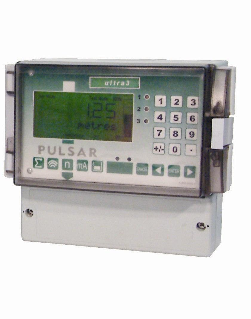
Level and Flow Measurement. Ultra Range. Ultra 3, Ultra 5 and UltraTwin
 Level and Flow Measurement Ultra Range Ultra 3, Ultra 5 and UltraTwin Ultra Range Ultra 3 Ultra sophistication in a smart package, Ultra 3 combines reliable non-contacting ultrasonic level and volume measurement,
Level and Flow Measurement. Flow Pulse
 Level and Flow Measurement Flow Pulse Flow Pulse : Unique, non-invasive clamp-on flow monitor Features Non-invasive, clamp-on Simple installation, no service interruption Use on all common pipe types,
Sludge PC INSTRUCTION MANUAL
 Sludge PC INSTRUCTION MANUAL PULSAR SLUDGE FINDER SERIES SLUDGE PC (FIRST EDITION) June 2012 Part Number M-920-PCS-001-0P COPYRIGHT Pulsar Process Measurement Limited, 1999-2012. All rights reserved.
Level and Flow Measurement. Blackbox
 Level and Flow Measurement Blackbox Blackbox Controllers: Level measurement made simple Features Compact low cost intelligent controllers Will operate on all db transducers up to 40m range Solids, powders
Blackbox Controllers:
 Blackbox Controllers: Level measurement made simple Compact low cost intelligent controllers Will operate on all db transducers up to 40m range Solids, powders and liquids level measurement Separation
SLUDGE FINDER 2 INSTRUCTION MANUAL
 SLUDGE FINDER 2 INSTRUCTION MANUAL SLUDGE FINDER 2 (SECOND EDITION REV.2 ) November 2012 Part Number M-920-0-002-1P COPYRIGHT Pulsar Process Measurement Limited, 2009-12. All rights reserved. No part
The PM1000 series is a universal 4 digit LED plug-on display for transmitters with 4-20mA 2 wire output and fitted with DIN43650 connector.
 PM1000 SERIES PLUG-ON DISPLAY BRIGHT LED DISPLAY INDICATION RANGE -999 TO +9999 FITS TO DIN 43650 CONNECTOR PLUG-ON TO ANY TRANSMITTER WITH 4-20MA OUTPUT EASY TO SCALE ON SITE ROBUST DESIGN SET POINT OPTION
STATUS Shiloh Road Alpharetta, Georgia (770) FAX (770) Toll Free
 FAX (770) Toll Free") Instruction Manual Model 1582-45L Data Switch September 2010, Rev A REMOTE LOCAL SWITCH STATUS SELECT REMOTE LOCAL LOCAL SELECT CHANNEL SELECT POWER MODEL 1582 SWITCH CROSS TECHNOLOGIES, INC. Data, drawings,
Instruction Manual Model 1582-45L Data Switch September 2010, Rev A REMOTE LOCAL SWITCH STATUS SELECT REMOTE LOCAL LOCAL SELECT CHANNEL SELECT POWER MODEL 1582 SWITCH CROSS TECHNOLOGIES, INC. Data, drawings,
POWER Shiloh Road Alpharetta, Georgia (770) FAX (770) Toll Free
 FAX (770) Toll Free") Instruction Manual Model 1582-10M Protection Switch January 2009 Rev O ALARMS MENU OUTPUT = CH1 AUTO POWER 1 2 MODEL 1582 SWITCH CROSS TECHNOLOGIES INC. CH1 CH2 REMOTE EXECUTE Data, drawings, and other
Instruction Manual Model 1582-10M Protection Switch January 2009 Rev O ALARMS MENU OUTPUT = CH1 AUTO POWER 1 2 MODEL 1582 SWITCH CROSS TECHNOLOGIES INC. CH1 CH2 REMOTE EXECUTE Data, drawings, and other
Sludge Finder 2 (UL) INSTRUCTION MANUAL
 INSTRUCTION MANUAL") Sludge Finder 2 (UL) INSTRUCTION MANUAL SLUDGE FINDER 2 (UL) (SECOND EDITION REV 1) May 2012 Part Number M-920-0-002-1U COPYRIGHT Pulsar Process Measurement Limited, 2009-12. All rights reserved. No part
Sludge Finder 2 (UL) INSTRUCTION MANUAL SLUDGE FINDER 2 (UL) (SECOND EDITION REV 1) May 2012 Part Number M-920-0-002-1U COPYRIGHT Pulsar Process Measurement Limited, 2009-12. All rights reserved. No part
Level and Flow Measurement. IMP Range
 Level and Flow Measurement IMP Range IMP IMP Standard 2/3 Wire IMP I.S. The IMP range offers a combined transducer and controller in one self contained unit. Non-contact level measurement of liquids or
SPECIFICATION FOR THE SUPPLY OF A BATTERY MONITORING SYSTEM
 SPECIFICATION FOR THE SUPPLY OF A BATTERY MONITORING SYSTEM ESG20020202-3-2 February 27 th 2008 Project number reference:- File Number:- Prepared by:- Company:- Address:- Copy Number:- of Intentionally
FLEX Ex Spring Clamp Terminal Base
 Installation Instructions FLEX Ex Spring Clamp Terminal Base (Cat. No. 1797-TB3S) 1 10 11 4 Only remove this cover plug if connecting another terminal base unit. 3 5 6 12 2 7 8 9 41253 Component Identification
Intelligent Transducers for Level Measurement
 dbi Series Transducers Intelligent Transducers for Level Measurement Features Self-contained Solids or liquids applications HART or Profibus PA DATEM digital echo processing Various mounting options Standards-compliant
QUALITY POWER SOLUTIONS BACKED UP BY REAL-WORLD ENGINEERING EXPERIENCE
 QUALITY POWER SOLUTIONS BACKED UP BY REAL-WORLD ENGINEERING EXPERIENCE User s Manual SR250HL Power Supply/ Float Charger for Lead Acid Batteries STANDARD FEATURES OPTIONAL FEATURES 3 Relay Alarms-Form
1/32-DIN TEMPERATURE CONTROLLER INSTALLATION, WIRING AND OPERATION MANUAL FORM 3882
 1/32-DIN TEMPERATURE CONTROLLER INSTALLATION, WIRING AND OPERATION MANUAL FORM 3882 This manual is intended for use in support of installation, commissioning and configuration of the 1/32-DIN Temperature
C160 Wall-/Pipe Mounted Universal Process Indicator
 Data sheet DS/ EN Rev. I Wall-/Pipe Mounted Universal Process Indicator reliable process indicator, wherever it s needed High visibility LED display the clearest view of your process status 0.1% measurement
SI3300. user and installation manual. 4-20mA/DC-Digital Display
 SI3300 4-20mA/DC-Digital Display The SI3300 is a member of the SI3000 Readout Family. All members of the family are marked SI3000 on the front panel. This manual is specifically for the SI3300 Model with
Wall-/Pipe Mounted Universal Process Indicator
 Data Sheet SS/_8 Wall-/Pipe Mounted Universal Process Indicator High visibility LED display the clearest view of your process status 0.1% measurement accuracy precise indication of process measurement
MYRIAD QLC 4-CHANNEL MONITOR/CONTROLLER INSTRUCTION MANUAL
 MYRIAD QLC 4-CHANNEL MONITOR/CONTROLLER INSTRUCTION MANUAL VISIT OUR WEBSITE SIGMACONTROLS.COM MYR QLC MANUAL 013114 2 TABLE OF CONTENTS INTRODUCTION 3 Ordering Information Specifications Features WIRING
INSTRUCTION MANUAL STATION CONTROLLER SC1000 MOTOR PROTECTION ELECTRONICS, INC.
 INSTRUCTION MANUAL STATION CONTROLLER SC1000 MOTOR PROTECTION ELECTRONICS, INC. 2464 Vulcan Road, Apopka, Florida 32703 Phone: (407) 299-3825 Fax: (407) 294-9435 Revision Date: 9-11-08 Applications: Simplex,
AVC 2 AUTOMATIC VOLUME CONTROL USERS MANUAL
 AVC 2 AUTOMATIC VOLUME CONTROL USERS MANUAL GENERAL DETAIL The AVC2 will control a stereo channel to a preset maximum output level allowing the maximum sound level of a system to be controlled. The AVC2
TRACKER 240 SERIES. Load Cell and Weighing Indicators. A Precision Measurement Instrument with Outstanding Features
 TRACKER 240 SERIES Load Cell and Weighing Indicators A Precision Measurement Instrument with Outstanding Features TRACKER 240 SERIES INDICATORS Ratiometric Measurement Tare and Auto Transducer Excitation
TRACKER 220 SERIES. Digital Panel Indicators. A Complete Range of Universal Input Digital Panel Indicators for Temperature and Process Measurement
 TRACKER 220 SERIES Digital Panel Indicators A Complete Range of Universal Input Digital Panel Indicators for Temperature and Process Measurement TRACKER 220 SERIES INDICATORS Universal Input Analogue Output
User's Guide. Extech AM A AC Analog Clamp Meter
 User's Guide Extech AM300 300A AC Analog Clamp Meter Introduction Congratulations on your purchase of the Extech AM300 Analog Clamp Meter. This device measure AC Voltage and Current, DC Voltage, and Resistance.
INSTALLATION DKM-409 NETWORK ANALYSER WITH HARMONIC MEASUREMENT AND SCOPEMETER. Before installation:
 DKM-409 NETWORK ANALYSER WITH HARMONIC MEASUREMENT AND SCOPEMETER The DKM-409 is a precision instrument designed for displaying various AC parameters in 3-phase distribution panels. Thanks to its isolated
DXTH DUCT SENSOR / SWITCH FOR TEMPERATURE AND HUMIDITY. Mounting and operating instructions
 DUAL DUCT SENSOR / SWITCH FOR TEMPERATURE AND HUMIDITY Mounting and operating instructions Table of contents SAFETY AND PRECAUTIONS 3 PRODUCT DESCRIPTION 4 ARTICLE CODES 4 INTENDED AREA OF USE 4 TECHNICAL
Power Meter PowerMonitor 500
 ROCKWELL AUTOMATION PROCUREMENT SPECIFICATION PROCUREMENT SPECIFICATION PowerMonitor 500 NOTICE: The specification guidelines in this document are intended to aid in the specification of products. Specific
MAXIMA+ Series Rotary Level Indicator
 MAXIMA+ Series Rotary Level Indicator BinMaster: Division of Garner Industries 7201 N. 98th St., Lincoln, NE 68507 402-434-9102 email: info@binmaster.com www.binmaster.com OPERATING INSTRUCTIONS PLEASE
MAXIMA + Series ROTARY LEVEL CONTROL
 Price $5.00 MAXIMA + Series ROTARY LEVEL CONTROL OPERATING INSTRUCTIONS PLEASE READ CAREFULLY Division of Garner Industries 7201 North 98th Street Lincoln, NE 68507-9741 (402) 434-9102 925-0268 Rev. A
Operating instructions. Speed monitor D / / 2014
 Operating instructions Speed monitor D200 80005257 / 00 05 / 2014 Contents 1 Preliminary note...4 1.1 Symbols used...4 1.2 Warning signs used...4 2 Safety instructions...5 2.1 General...5 2.2 Target group...5
SC2000 MOTOR PROTECTION ELECTRONICS, INC. INSTRUCTION MANUAL. (407) Phone: Website:
 Phone: Website:") SC2000 INSTRUCTION MANUAL MOTOR PROTECTION ELECTRONICS, INC. 2464 Vulcan Road Apopka, Florida 32703 Phone: Website: (407) 299-3825 www.mpelectronics.com Operating Program Revision: 12 Revision Date: 8-27-14
SC2000 INSTRUCTION MANUAL MOTOR PROTECTION ELECTRONICS, INC. 2464 Vulcan Road Apopka, Florida 32703 Phone: Website: (407) 299-3825 www.mpelectronics.com Operating Program Revision: 12 Revision Date: 8-27-14
Press the PEN HOME key to move the pen(s) to the outside of the chart. The pen(s) is automatically raised off the chart.
 to the outside of the chart. The pen(s) is automatically raised off the chart.") DICKSON GETTING STARTED 7-day chart rotation 0 to 100 o F KT8P0/2/3 & KT856 Remote Sensing Temperature Recorder QUICK START 1. Remove the protective pen cap(s). 2. Connect Probe(s): a. KT8P0/2/3: Make
DICKSON GETTING STARTED 7-day chart rotation 0 to 100 o F KT8P0/2/3 & KT856 Remote Sensing Temperature Recorder QUICK START 1. Remove the protective pen cap(s). 2. Connect Probe(s): a. KT8P0/2/3: Make
Conveyor Belt Alignment Switches from IDEM
 Conveyor Belt Alignment Switches from IDEM Data Sheet Die-Cast Models Python Line Series Stainless Steel Models Using Conveyor Belt Alignment Switches Application: Conveyor Belt Alignment switches are
The Tracker 220 Series A Complete Range of Universal Input Digital Panel Indicators for Temperature and Process Measurement
 Acquisition Measurement Control The Tracker 220 Series A Complete Range of Universal Input Digital Panel Indicators for Temperature and Process Measurement TRACKER 220 SERIES INDICATORS Universal Input
DS BAS /99 UNC 596 BUILDING AUTOMATION SYSTEM UNIVERSAL NETWORK CONTROLLER FEATURES
 DS 13.321 BAS 2800+ 06/99 UNC 596 BUILDING AUTOMATION SYSTEM UNIVERSAL NETWORK CONTROLLER Specification no. 579-1-904 The Universal Network Controller (UNC 596) is fully intelligent and incorporates its
Engineering Specifications HydroRanger 200. Multi-Functional Level Control System
 General Engineering Specifications HydroRanger 200 Multi-Functional Level Control System Scope This section describes the requirements for a multi-functional level controller system. Under this item, the
DSTHM-2 COMBINED T AND RH DUCT TRANSMITTER. Mounting and operating instructions
 Mounting and operating instructions Table of contents SAFETY AND PRECAUTIONS 3 PRODUCT DESCRIPTION 4 ARTICLE CODES 4 INTENDED AREA OF USE 4 TECHNICAL DATA 4 STANDARDS 4 OPERATIONAL DIAGRAMS 5 WIRING AND
Level and Flow Measurement. dbi Transducers. HART and Profibus PA Intelligent Transducers
 Level and Flow Measurement dbi Transducers HART and Profibus PA Intelligent Transducers dbi Series Transducers: HART and Profibus PA Ultrasonic Transducers for Level Measurement Features Self-contained
MYRIAD LC1 LEVEL CONTROLLER INSTRUCTION MANUAL
 MYRIAD LC1 LEVEL CONTROLLER INSTRUCTION MANUAL VISIT OUR WEBSITE SIGMACONTROLS.COM MYR LC1 MANUAL 062114 TABLE OF CONTENTS INTRODUCTION 3 Ordering Information Specifications Features Dimensions WIRING
Operating Instructions VEGAMET 381
 Operating Instructions VEGAMET 381 in out Contents Contents 1 About this document... 4 1.1 Function... 4 1.2 Target group... 4 1.3 Symbolism used... 4 2 For your safety... 6 2.1 Authorised personnel...
The power behind competitiveness. Delta Infrasuite Power Management. Power Distribution Unit. User Manual.
 The power behind competitiveness Delta Infrasuite Power Management Power Distribution Unit User Manual www.deltapowersolutions.com Save This Manual This manual contains important instructions and warnings
dbi Series ( ) Intelligent Transducer INSTRUCTION MANUAL
 Intelligent Transducer INSTRUCTION MANUAL") dbi Series ( ) Intelligent Transducer INSTRUCTION MANUAL dbi SERIES (HART) INTELLIGENT TRANSDUCER (FIRST EDITION REV 1) September 2012 Part Number M-dBi-H-001-1P COPYRIGHT Pulsar Process Measurement Limited,
dbi Series ( ) Intelligent Transducer INSTRUCTION MANUAL dbi SERIES (HART) INTELLIGENT TRANSDUCER (FIRST EDITION REV 1) September 2012 Part Number M-dBi-H-001-1P COPYRIGHT Pulsar Process Measurement Limited,
SLI 15 INVERTER SERIES, 1500 W
 SLI 15 INVERTER SERIES, 1500 W FEATURES DESCRIPTION New, compact design: 1U height x 19" width x 14.94" depth; 19" rack-mountable High efficiency: up to 93% True sine wave output Parallelable output with
EPS Power Supply
 EPS - 600 Power Supply Installation and Operation Manual Version 1.0 *This instrument is intended for laboratory use only Index A. Important Notice ----------------------------------------------------------------
Line Impedance Stabilization Network (LISN)
") Model 3816/2 Line Impedance Stabilization Network (LISN) User Manual ETS-Lindgren Inc. reserves the right to make changes to any product described herein in order to improve function, design, or for any
Model 3816/2 Line Impedance Stabilization Network (LISN) User Manual ETS-Lindgren Inc. reserves the right to make changes to any product described herein in order to improve function, design, or for any
Signet Pressure Transmitter
 Signet 850 Pressure English *850.090* 850.090 Rev. H /06 English CAUTION! Remove power to unit before wiring input and output connections. Follow instructions carefully to avoid personal injury. Contents.
UDC 1000 and UDC 1500 MICRO-PRO SERIES UNIVERSAL DIGITAL CONTROLLERS
 UDC 1000 and UDC 1500 MICRO-PRO SERIES UNIVERSAL DIGITAL CONTROLLERS EN0I-6041 12/99 PRODUCT SPECIFICATION SHEET OVERVIEW The UDC 1000 and UDC 1500 are microprocessor-based 1/16 DIN and 1/8 DIN controllers
OZONE SWITCH Model OS-6. OS-6 Features
 USER MANUAL OZONE SWITCH Model OS-6 OS-6 Features The OS-6 is an industrial grade ozone controller and monitor. The OS-6 design is optimized for accuracy and ease of installation, setup and operation.
user and installation manual
 SI3500 SI3500 ORBIT Digital Display The SI3500 is a member of the SI3000 Readout Family. All members of the family are marked SI3000 on the front panel. This manual is specifically for the SI3500 Model
100mm Process Indicator Recorder
 Data Sheet SS/_3 100mm Process Indicator Recorder One or two pen continuous line 100mm recorder universal input for thermocouple, RTD, mv, ma and V Clear, 5-digit LED display high visibility, wide viewing
SC2000 MOTOR PROTECTION ELECTRONICS, INC. INSTRUCTION MANUAL. Phone: (407) Fax: (407) Vulcan Road Apopka, Florida 32703
 Fax: (407) Vulcan Road Apopka, Florida 32703") SC2000 INSTRUCTION MANUAL MOTOR PROTECTION ELECTRONICS, INC. 2464 Vulcan Road Apopka, Florida 32703 Phone: (407) 299-3825 Fax: (407) 294-9435 Operating Program Revision: 10 Revision Date: 1-9-12 STATION
SC2000 INSTRUCTION MANUAL MOTOR PROTECTION ELECTRONICS, INC. 2464 Vulcan Road Apopka, Florida 32703 Phone: (407) 299-3825 Fax: (407) 294-9435 Operating Program Revision: 10 Revision Date: 1-9-12 STATION
A0-10 ANALOG OUTPUT. Instruction Manual April 2001 NALOG OUTPUT
 A0-10 ANALOG OUTPUT Instruction Manual April 2001 NALOG OUTPUT Safety Guidelines Warning notices must be observed to ensure personal safety as well as that of others, and to protect the product and the
dbi Series ( ) Intelligent Transducer INSTRUCTION MANUAL
 Intelligent Transducer INSTRUCTION MANUAL") dbi Series ( ) Intelligent Transducer INSTRUCTION MANUAL dbi SERIES (HART) INTELLIGENT TRANSDUCER (FIRST EDITION REV 3) June 2017 Part Number M-dBi-H-001-3P COPYRIGHT Pulsar Process Measurement Limited,
dbi Series ( ) Intelligent Transducer INSTRUCTION MANUAL dbi SERIES (HART) INTELLIGENT TRANSDUCER (FIRST EDITION REV 3) June 2017 Part Number M-dBi-H-001-3P COPYRIGHT Pulsar Process Measurement Limited,
Badger Meter Europa GmbH. INSTRUCTION MANUAL Deluxe LCD display for the MN series. September Version MN-Deluxe LCD display-09/01-e
 Badger Meter Europa GmbH INSTRUCTION MANUAL Deluxe LCD display for the MN series September 2001 Version MN-Deluxe LCD display-09/01-e Content Content Page 1. To the owner 1 2. Important information 1 3.
Operation Manual. Concorde 600 Power Supply. *This instrument is intended for laboratory use only.
 Concorde 600 Power Supply Operation Manual Cat.no. R10-1001011 *This instrument is intended for laboratory use only http://www.recenttec.com E-mail : support@recenttec.com Version 1.1 Packing List x 1
Installation, Testing, and Operating Procedures 30 AMP PORTABLE AND PERMANENT SERIES GFCI SINGLE and MULTIPHASE
 IMPORTANT! Please read all the information on this sheet. SAVE THESE INSTRUCTIONS! NOTICE BEFORE USING READ INSTRUCTIONS COMPLETELY. TO BE INSTALLED BY A QUALIFIED ELECTRICIAN IN ACCORDANCE WITH NATIONAL
RXTH DUAL ROOM SENSOR / SWITCH
 DUAL ROOM SENSOR / SWITCH FOR TEMPERATURE AND RELATIVE HUMIDITY Mounting and operating instructions Table of contents SAFETY AND PRECAUTIONS 3 PRODUCT DESCRIPTION 4 ARTICLE CODES 4 INTENDED AREA OF USE
User's Guide. Phase Sequence and Motor Rotation Tester Model
 User's Guide Phase Sequence and Motor Rotation Tester Model 480403 Introduction Congratulations on your purchase of the Extech Model 408403 Motor and Phase Rotation Indicator. This handheld instrument
Multi-Point Gas Detection and Control System
 Multi-Point Gas Detection and Control System Specifications subject to change without notice. USA 40804 Page of 7 DESCRIPTION Wall mounted, microprocessor-based, multi-point, analog electronic control
PanelView Plus/VersaView CE Terminals and Display Modules
 Installation Instructions PanelView Plus/VersaView CE Terminals and Display Modules (Catalog Numbers 2711P-xxxxxx, 6182H-xxxxxx) English Inside: Overview...2 For More Information...2 Modular Components...3
RST ROOM TEMPERATURE TRANSMITTER. Mounting and operating instructions
 Mounting and operating instructions Table of contents SAFETY AND PRECAUTIONS 3 PRODUCT DESCRIPTION 4 ARTICLE CODES 4 INTENDED AREA OF USE 4 TECHNICAL DATA 4 STANDARDS 4 OPERATIONAL DIAGRAM 5 WIRING AND
Model 7705 Control Module
 www.keithley.com Model 7705 Control Module User s Guide PA-696 Rev. D / October 2006 A G R E A T E R M E A S U R E O F C O N F I D E N C E Safety Precautions The following safety precautions should be
NL-02 NL-02. The NL-02 InoxLaser uses time-offlight laser technology for continuous non-contact distance or level measurement.
 www.lightware.co.za info@lightware.co.za The InoxLaser uses time-offlight laser technology for continuous non-contact distance or level measurement. Able to measure to any solid surface, at any angle,
REDUNDANCY MODULE TSP-REM360 AND TSP-REM600
 REDUNDANCY MODULE TSP-REM360 AND TSP-REM600 Operating Instructions Seite 1 Dimensions drawings: TSP-REM360 Weight: 0.882lb Gewicht: 0.40kg Seite 2 Dimensions drawings: TSP-REM600 Bottom view Top view Side
INSTRUCTION MANUAL. Universal AC Input Switching Power Supply 24 Vdc Output DIN-Rail Models PSD1000, PSD1000F PSD PSD1000F
 PSD1000 - PSD1000F INSTRUCTION MANUAL Universal AC Input Switching Power Supply 24 Vdc Output DIN-Rail Models PSD1000, PSD1000F PSD1000 - Universal AC Input Switching Power Supply 24 Vdc Output ISM0089-4
/8 DIN Universal Process Indicator
 Data Sheet SS/_ High visibility LED display the clearest view of your process status.% measurement accuracy precise indication of process measurement Analog and relay outputs as standard alarm and retransmission
USER MANUAL VIBRATION CONTROL RMA-POWER-BOX 107/230
 USER MANUAL VIBRATION CONTROL Version 2.2 1 IMPORTANT NOTES Electrical danger within the meaning of this documentation or the warning labels on the product itself respectively means that death, serious
MODEL 8000MP LEVEL SENSOR
 1 MODEL 8000MP LEVEL SENSOR INSTRUCTIONS FOR INSTALLATION, OPERATION & MAINTENANCE VISIT OUR WEBSITE SIGMACONTROLS.COM 2 SERIES 8000MP LEVEL SENSOR 1. DESCRIPTION The Model 8000MP Submersible Level Sensor
Intrinsically safe batch controller Batching Master 110i
 Intrinsically safe batch controller Batching Master 110i Installation Guide BVS 04 AT E 172 Revision 12.2 IBS BatchControl GmbH Im Sträßchen 2-4 Tel.: ++49 2441 9199 801 53925 Kall Fax.: ++49 2441 9199
Mini Digital Multimeter
 User's Guide Mini Digital Multimeter Model MN15 Introduction Congratulations on your purchase of the Extech MN15 MultiMeter. The MN15 offers AC/DC Voltage, AC/DC Current, Resistance, Diode, and Continuity
RXTP ROOM TEMPERATURE
 ROOM TEMPERATURE CONTROLLER WITH PI CONTROL Mounting and operating instructions Table of contents SAFETY AND PRECAUTIONS 3 PRODUCT DESCRIPTION 4 ARTICLE CODES 4 INTENDED AREA OF USE 4 TECHNICAL DATA 4
Operating Manual RISH DPM Hz
 Operating Manual RISH DPM 72mm x 144mm 96mm x 96mm 48mm x 96mm 2-60-006-00-00512_Rev. B - 7/2016 DIGITAL MULTIFUNCTION INSTRUMENT Programmable Digital Panel Meter Installation & Operating Instructions
Operating Instructions
 PRIMETEST 100 PRIMETEST 100 Bracken Hill South West Industrial Estate Peterlee Co Durham SR8 2SW ENGLAND Tel: +44(0)191 5863511 www.seaward.co.uk sales@seaward.co.uk service@seaward.co.uk Part Number
RTT2 ROOM TEMPERATURE SWITCH. Mounting and operating instructions
 Mounting and operating instructions Table of contents SAFETY AND PRECAUTIONS PRODUCT DESCRIPTION ARTICLE CODES INTENDED AREA OF USE TECHNICAL DATA STANDARDS OPERATIONAL DIAGRAMS WIRING AND CONNECTIONS
Installation & Operation
 LED Readout Installation & Operation WARRANTY Accurate Technology, Inc. warrants the ProScale Systems against defective parts and workmanship for 1 year commencing from the date of original purchase. Upon
User s Guide. 600A AC Clamp Meter. Model 38387
 User s Guide 600A AC Clamp Meter Model 38387 Safety International Safety Symbols This symbol, adjacent to another symbol or terminal, indicates the user must refer to the manual for further information.
G3NE. Model Number Structure. Solid State Relays. Model Number Legend. Compact, Low-cost, SSR Switching 5 to 20 A
 Solid State Relays CSM DS_E_4_1 Compact, Low-cost, SSR Switching 5 to 20 A Wide load voltage range: 75 to 264 VAC. Both 100-V and 200-V loads can be handled with the same model. Dedicated, compact aluminum
I/O SIGNAL CONDITIONER
 Technical Data Sheet No. TD9809M Rev. F Date of Issue: December 9, 2009 OPERATING MANUAL I/O SIGNAL CONDITIONER CAUTION: THIS PRODUCT DOES NOT PROVIDE GALVANIC ISOLATION. DO NOT ATTEMPT USE OF THIS PRODUCT
Conductive Level Controller
 Conductive Level Controller 61F-D21T-V1 Ideal for level control for industrial facilities and equipment. Outputs can be set to self-hold at ON or OFF using self-holding circuits. Sensitivity adjustment
The IQ300 wall mount load cell indicator is a precision digital indicator for load cell and strain gauge applications.
 IQ300 Wall Mount Load Cell Indicator Data sheet English 1.01 Introduction The IQ300 wall mount load cell indicator is a precision digital indicator for load cell and strain gauge applications. The high
ATS01N232RT soft starter for asynchronous motor - ATS01-32 A V
 Characteristics soft starter for asynchronous motor - ATS01-32 A - 460..480 V Complementary Assembly style Function available Power supply voltage limits Main Range of product Altistart 01 Product or component
Data Manager Installation Guide
 PR05XX Data Manager Installation Guide Resource Data Management Ltd 80 Johnstone Avenue, Hillington Industrial Estate, Glasgow, Scotland G52 4NZ UK +44(0)141 810 2828 Switchboard support@resourcedm.com
TC100 Precision Thermocouple Calibrator
 TC100 Precision Thermocouple Calibrator Table of Contents 1. Introduction.....................1 2. Accessories....................5 3. Set-Up Basic/Advanced...........5 4. Operating Procedure.............6
SP6R Level Controller Operation Manual
 SP6R Level Controller Operation Manual www.sjerhombus.com SP6R LEVEL CONTROLLER INTRODUCTION SJE-Rhombus, an industry leader in water and wastewater pump controls, introduces the SP6R Level Controller.
Models beginning with 2M, 2L or 2X. Product Description. Technical Specifications. Installation Instructions. Series 2000 Multiple Meter Units (MMUs)
") Models beginning with 2M, 2L or 2X Series 2000 Multiple Meter Units (MMUs) Product Description Technical Specifications Installation Instructions February 28 th, 2013 List of Figures...2 List of Tables...2
Models beginning with 2M, 2L or 2X Series 2000 Multiple Meter Units (MMUs) Product Description Technical Specifications Installation Instructions February 28 th, 2013 List of Figures...2 List of Tables...2
LAUREL. Laureate Digital Panel Meter for Process and Ratiometric Signals ELECTRONICS, INC. Features. Description
 LAUREL ELECTRONICS, INC. Laureate Digital Panel Meter for Process and Ratiometric Signals Features Reads process signals from ±200 mv to ±600V or ±2 ma to ±5A full scale Ratiometric mode for bridges and
Product Manual ASL Document Ref.: U doc Issue: 04 complete, approved - Date: 16/08/10 Part Number: M0618_23
 Product Manual ASL Document Ref.: U-0618-0103.doc Issue: 04 complete, approved - Date: 16/08/10 Part Number: M0618_23 RCS01 RPA Transmitter Charging Station This equipment is designed and manufactured
2 Table of Contents 1. TABLE OF CONTENTS. 1. Table of Contents Introduction Wiring Diagram Terminals Review...
 TPR-6 Temperature Protection Relay Instruction Manual Ver. June 1 st 2010 2 Table of Contents 1. TABLE OF CONTENTS 1. Table of Contents... 2 2. Introduction... 3 3. Wiring Diagram... 5 4. Terminals Review...