*Note: Windows is a registered trademark of Microsoft Corporation in the United States and other countries. Figure 1.
|
|
|
- Annabelle Crawford
- 5 years ago
- Views:
Transcription


1 EVALUATION DONGLE TEMPERATURE AND HUMIDITY SENSORS 1. Introduction This user s guide describes the evaluation GUI and PCB board design for the following evaluation kits: Si701USB-DONGLE kit for Si701, Si700, and Si701 Si70--EVB kit for Si70 and Si70 Si EVB kit for Si7006 and Si7007 Si700///-EVB kits for Si700, Si70, Si70 and Si70 temperature sensors Si70-EVB kit The GUI and USB dongle support both PWM output and I C output devices.. Evaluation Kit Descriptions All of the supported evaluation kits contain the following items: Si701USB-DONGLE evaluation board consisting of one Si701 sensor as well as USB interface and circuitry for evaluation of the Si701 with thermistor or other analog input -foot flat cable to connect the postage stamp boards to the USB dongle USB extender cable Windows graphical user interface software for complete control of the Si70xx sensors (Windows XP, VISTA, or 7 required) Depending on the kit, different postage stamp boards are supplied as well. The Si701USB-Dongle kit has Si701,Si700, and Si701 I C postage stamp boards. The Si70--EVB kit contains Si70 and Si70 PWM output boards. The Si EVB kit contains Si7006 and Si7007 low-cost postage stamp boards. The Si700///-EVB kits contain the appropriate Si700, Si70, Si70 or Si70 temperature sensor postage stamp. The Si70 kit contains the Si70 postage stamp. Using the Si701 USB-dongle, the Windows GUI will also support postage stamp size boards for the Si700 first-generation temperature and humidity sensor in a x mm package (Si700-EB) as well as the Si701 pin-compatible upgrade of this part (Si701-EB). The Windows* GUI will also support the older version Si700USB-dongle although not all features of the newer parts can be evaluated in this case. *Note: Windows is a registered trademark of Microsoft Corporation in the United States and other countries. Figure 1. Si701USB-DONGLE Rev. 0.7 /1 Copyright 01 by Silicon Laboratories Si701USB-DONGLE


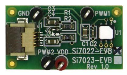
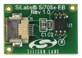

2 Figure. Si7006, Si7007, Si701, Si700/1, Si70/, Si70, and Si70x Evaluation Boards Rev. 0.7

3 . Software Setup It is important that the software be installed before connecting the USB dongle to the PC; this ensures that the software drivers are correctly installed. To set up the software, run the file, setup.exe, from the supplied software installation disk. The Si701 USB dongle demo platform was developed based on the National Instruments LabView platform. To install it, you must accept the National Instruments end-user license agreement shown in Figure. Figure. National Instruments Software License Agreement Rev. 0.7

4 Continue through the following screens, which track the Graphical User Interface installation. Figure. Start Installation Screen Rev. 0.7

5 Figure. Installer Update Screen Rev. 0.7

6 After this screen, you will see the installer for the Si701 device drivers. Figure 6. Device Drivers Installer Screen 6 Rev. 0.7
7 . Hardware Setup and Software Operation Once the GUI installation is complete, connect the Si701 USB dongle to your PC. Your PC should automatically recognize the USB dongle and use the newly-installed driver. Next, find the icon for the Si701 GUI, which should be easily found under recently-installed programs from the start menu, under Programs Silicon Laboratories Si70xx Evaluation Software or at C:\Program Files (x86)\silicon Laboratories\Si70xx With all the hardware plugged in and once your PC identifies the USB dongle, launch the GUI. The GUI itself is simple to use. Figure 7 shows a screenshot of the GUI. Figure 7. GUI Screen Note: This is the GUI screen when an additional Si700-EB is used. The appearance will change according to the number of sensors detected. The USB dongle contains one Si701 relative humidity and temperature sensor and can also support one additional sensor at connector J. All Si70xx sensor evaluation boards are supported. Note: The "postage stamp" boards are used on this connector with the -foot flat flexible cable. To use the cable, carefully lift the darker brown piece of the connector and insert the cable with the metal fingers of the cable facing the metal fingers of the connector then close the connector on the cable (see also figures 1 and ). If a new postage stamp board is inserted into a powered dongle, click the INIT button on the GUI. Rev

8 When the GUI is started, it will recognize the sensors that are connected. The INIT button should be pressed if the hardware wasn t connected or was changed after the GUI was started. The analog output devices, Si7007, Si70, and Si70, do not have a device ID capability. Analog output is advertised by shorting the SDA pin of the 6-pin connector low. In these cases the GUI reports analog output device because it is not possible to know which device is connected. Select temperature units by clicking on the Select Temperature Units button.the button will toggle between Deg C and Deg F indicating the selection of either degrees Celsius or degrees Fahrenheit. In the Enter Sample Interval (seconds) number box, the time interval between samples can be entered as any value greater than 0. seconds in increments of 0.1 seconds. Depending on the number of devices connected, sample times less than 1 second might not be possible. In this case, the window will turn red and the sample time will be as short as possible. The upper chart by default displays temperature; this can be changed to dew point by clicking on the selection box located directly under the Silicon Labs logo. The temperature and dew point should always be logged regardless of setting. The default Y-axis range on each chart auto-ranges. If desired, the auto-ranging can be turned off and the upper and lower limits for the charts can be set by clicking on the appropriate box. The same configuration changes can be made to the X-axis. If a log of the data is desired, click START inside the Log Data to File box to begin collecting data. If Create Log File? is enabled, a dialog box will appear requesting a file name and save location. The time base of the log file can be chosen to be absolute date and time or relative time in seconds. To stop data collection, click STOP. To exit the GUI click QUIT. If an Si700 or Si701 evaluation board is connected, the GUI automatically adjusts for the temperature and non-linearity effect of the RH sensor. (This is not required for the other sensors as this is done internally to the part). The data logged to file is saved in comma separated value (csv) format, which can be easily opened in a spreadsheet application such as Microsoft Excel, as shown in Figure 8. Figure 8. Logged Data Displayed in Excel with Absolute Date and Time Base 8 Rev. 0.7
9 .1. Configuration Screen Si701USB-DONGLE The configuration screen displays the configuration settings for the device that is connected. Figure 9. Configuration Screen For Si701, this includes: The device ID information (an 8-byte identification that is unique to each device) Configuration and enable settings for the on-chip heater. While the on-chip heater can go as high as 9 ma, the GUI only supports 9 ma maximum to avoid drawing too much power from the USB port. Conversion speed settings for the RH and temperature sensor Control of the voltage conversion settings (Si701 user register ) An option to disable the Si701 on the USB dongle is included for the case where the device connected to J is of more interest. Rev
10 .. Voltage Measurement Screen The voltage measurement screen configures the lookup table based on linearization of analog measurements for Si701. This is discussed in more detail in the Si701 data sheet and also in AN607. Figure 10. Voltage Measurement Screen The graph and output window in the upper section of this page shows the measurement result. The graph can be configured as in the previous discussion of graphs on the main page. By default, the linearization is configured to support the NCP18XH10F0RB thermistor with. k bias resistors supplied on the evaluation board. The lookup table is chosen so that the linearization results in an output code that is linear with temperature and scaled in the same way as the temperature sensor internal to the Si701. If the linearization coefficients have not been written to the Si701 part the lookup table entries are applied by the GUI and the resultant linearized (temperature) output can be graphed on the main page. In this case the coefficients can be modified to try different lookup tables. Prior to writing the coefficients to the Si701, the coefficients in the GUI entry boxes can be saved and later loaded. (They are saved to the file Si701.ini in the directory where the GUI executable is located). Clicking the Program coefficients button writes the coefficients to the part. This is a one-time process. After doing the write, close the GUI and cycle power. After doing this, the internal correction can be enabled on the configuration screen (lower right) and when enabled the corrected data will be displayed on the measurement screen as well as the main screen (if enabled). 10 Rev. 0.7
11 .. Calculation of Dew Point Value Si701USB-DONGLE The Si701 measures both temperature (T) and relative humidity (RH). These two values can be used to approximate the dew point (Td). bt,rh T d = a T,RH Where T,RH at RH = b + T ln 100 a = 17.6 b =.0 The calculation used is based on the August-Roche-Magnus approximation for the saturation vapor pressure of water in air as a function of temperature, it is considered valid for: 0 C < T < 60 C 1% < RH < 100% 0 C < Td < 0 C Rev
12 . Si701 USB Dongle Description The USB dongle facilitates communication between the Si701 and the optional postage stamp size evaluation board and a PC. This function is enabled by the Silicon Laboratories' C801F81 microcontroller. The optional postage stamp board is connected to connector J by a 6 wire flat flexible cable. The pin connections for connector J are shown in Figure 10. A full circuit diagram of the board is shown in Figure VDD CS/ Analog 1 USB DONGLE RIBBON CONNECTOR GND SDA GND Si70xx EB RIBBON CONNECTOR 1 SCL 6.1. Si701 USB Dongle Schematic Figure 11. Ribbon Cable Pin Assignments The Si701 USB-DONGLE is a simple board that contains a Si701 relative humidity and temperature sensor, a C801F81 USB microcontroller, a USB type A connector, and an auxiliary connector for connection to a second sensor. There is also support for a thermistor or other analog input. The thermistor and bias circuitry is connected by J, J, and J which are small solder bridges. To disconnect the thermistor and use the analog input directly (TP6 and TP7), simply use a soldering iron to remove the solder bridges on J and J. Solder wick may aid in removing the bridge, but is usually not required. 1 Rev. 0.7
13 RESETn GND CCK CD R1 10K TPV SDA SCL SCL thermistor interface +V C6.7uF C7 0.1uF R10 10K TPV6 R K U1 1 Si701 SDA VSNS ADD/VOUT R7 0 R9 0 TP7 VINP/remote thermistor R1 J.K C 0.1uF VDDA 8 VDDD 9 10 SCL 6 VINN 7 VINP 6 GNDD EPAD GNDA GND C1.7uF C 0.1uF J1 R 10K D AMBER R17 0 R 0 NC R1 10K -t P1 USB TYPE A +V 1 D- D+ GND C 0.1uF 1K R11 U C801F81 R K TPV7 R8 0 C 0.1uF J NC NC R1.K TP6 VINN/remote thermistor TP GND 6 SH SH REGIN 7 VBUS 8 GND VDD 6 D1 SP00BAHT 9 10 D- D+ RST/CCK P.0/CD C8 0.1uF P0.0 P0.1 P0. P0. P0. P0. P0.6 P0.7 P1.0 P1.1 P1. P1. P1. P1. P1.6 P1.7 P.0 P.1 P. P. P. P. P.6 P R6 RST SDA Figure 1. USB Dongle Circuit Schematic J VDD FH1 6 CS TP 6 SDA TP1 SCL TP 1 1 TP J Rev

14 .. Si701 USB Dongle Board Layers Figure 1. Si701 Dongle Board Layout Top Layer Figure 1. Si701 Dongle Board Layout Bottom Layer Note from Figures 1 and 16 that there is no ground plane around the Si701 and that there is a cutout in the PCB between the Si701 and other circuitry. While these are not requirements for successful operation of the Si701, they do (in the case of the dongle board) provide thermal isolation from heat sources, such as the host PC and MCU circuitry. There is also a second thermal cutout to provide isolation between the thermistor and Si Si701 USB Dongle Board Firmware For board firmware revisions less than, when using the Si701 dongle board at the end of the USB extension cable, there will be approximately 0.8 C of heating from the USB MCU despite the use of the thermal cutouts. This amount of heating will reduce the local humidity in the vicinity of the Si701 by as much as % (the error linearly increases from zero to % as the ambient humidity increases from zero to 100%). For more accurate determination of the humidity, the optional postage stamp size evaluation boards can be used. For board revision or greater, the heating has been reduced to about 0. C and can usually be ignored. Firmware revision is required for the analog output boards. If the MCU senses SDA is tied low it assumes the board is analog output. Boards with firmware revision or higher have a sticker to indicate this. An easy way to be sure of the board firmware revision is that the LED is constantly on after the GUI recognizes the board for older firmware revisions but only blinks when there is USB activity for newer firmware revisions. 1 Rev. 0.7
15 6. Optional Postage Stamp Evaluation Boards 6.1. Si701 EB Schematic Si701USB-DONGLE The evaluation board is a simple board containing just the Si701 sensor, decoupling capacitors, thermistor interface, and a ribbon connector for connection to the USB dongle board. C1.7uF U1 1 SDA VSNS ADD/VOUT TP7 VINP/remote thermistor Si701 TPV thermistor interface VDDA 8 VDDD 9 10 SCL VINP 6 VINN 7 R1 10K GNDD EPAD GNDA GND -t J1 1 6 FH1 1 6 C 0.1uF TPV R17 0 TPV7 J NC TPV6 J NC TP6 VINN/remote thermistor TPV Figure 1. Si701 EB Schematic C 0.1uF C 0.1uF R1.K J NC R1.K Rev
16 6.. Si7006, Si700/1, or Si700/// EB Schematic The evaluation board is a simple board containing just the Si7006/0/1/0// or Si70, decoupling capacitors and a ribbon connector for connection to the USB dongle board. The populated part number is indicated by a check box on the silkscreen on the top of the PCB. Figure 16. Si7006, Si700/1, or Si700/// EB Schematic 16 Rev. 0.7
17 6.. Si700/1 EB Schematic Si701USB-DONGLE The evaluation board is a simple board containing just the Si700 or Si701 sensor, decoupling capacitors and a ribbon connector for connection to the USB dongle board. The part number is populated and indicated by a check box. Figure 17. Si700/1 EB Schematic Rev
18 6.. Si7007, Si70, and Si70 EVB Schematic These evaluation boards contain the Si7007, Si70 or Si70 PWM output parts. An RC filter is included to convert the PWM output to an analog voltage referenced to VDD. The MCU on the Si701 USB dongle digitizes the analog voltage using an A/D converter that has VDD as a reference which allows accurate determination of the PWM output value. Grounding this pin identifies the board as analog. Figure 18. Si7007, Si70, and Si70 EVB Schematic 18 Rev. 0.7
19 6.. Si70 EVB Schematic Si701USB-DONGLE The Si70 evaluation board has a. to 1.8 V LDO for the Si70, decoupling capacitors, and a ribbon connector for connection to the USB dongle board. No I C level translation is required because the Si70 I C inputs are. V tolerant. U IN C.7uF TPS79718 VOUT NC GND PG 1 SCL VDD 1 TPV VDD U1 Si70 NC 6 TPV1 J C1.7uF C 0.1uF SDA TPV SDA VSS TPV6 SCL NC TPV GND TPV FH1 Figure 19. Si70 Schematic Rev
20 7. Additional Reference Resources Si700/6/7/1/1/0/1////0/// data sheets AN607: Si70xx Humidity Sensor Designer s Guide 8. GUI Revision Notes As explained in section. Si701 USB Dongle Description, firmware Revision of the USB adapter board reduces self-heating of the USB board. GUI Revision..0 Corrects a minor problem in the data logging which resulted in small output fluctuations that were not real. Adds support for disabling the device in the USB dongle. Improves the timing accuracy for the sampling interval. Adds support for other heater current settings for Si700 and Si701. Allows removal of individual graphs by clicking the green radar button for that graph. GUI Revision.0 Adds support for the Si70x temperature sensors. GUI revision.0 also includes support for the Si70. 0 Rev. 0.7
21 DOCUMENT CHANGE LIST Revision 0.1 to Revision 0. Updated ". Evaluation Kit Descriptions" on page 1. Added Si700-EB postage stamp size evaluation board for the Si700. Revision 0. to Revision 0. Updated ". Hardware Setup and Software Operation" on page 7. Updated Figure 7, GUI Screen, on page 7. Updated ".1. Configuration Screen" on page 9. Updated Figure 9, Configuration Screen, on page 9. Updated Figure 10, Voltage Measurement Screen, on page 10. Updated ".. Si701 USB Dongle Board Layers" on page 1. Added "8. GUI Revision Notes" on page 0. Revision 0. to Revision 0. Updated "1. Introduction" on page 1. Updated ". Evaluation Kit Descriptions" on page 1. Updated ". Software Setup" on page. Updated ". Hardware Setup and Software Operation" on page 7. Updated ". Si701 USB Dongle Description" on page 1. Updated ".. Si701 USB Dongle Board Layers" on page 1. Updated "6.. Si7006, Si700/1, or Si700/// EB Schematic" on page 16. Added "6.. Si7007, Si70, and Si70 EVB Schematic" on page 18. Revision 0. to Revision 0.6 Added support for the Si70x temperature sensors. Revision 0.6 to Revision 0.7 Added support for Si70. Rev
22 CONTACT INFORMATION Silicon Laboratories Inc. 00 West Cesar Chavez Austin, TX Tel: 1+(1) Fax: 1+(1) Toll Free: 1+(877) -0 Please visit the Silicon Labs Technical Support web page: and register to submit a technical support request. Patent Notice Silicon Labs invests in research and development to help our customers differentiate in the market with innovative low-power, small size, analog-intensive mixed-signal solutions. Silicon Labs' extensive patent portfolio is a testament to our unique approach and world-class engineering team. The information in this document is believed to be accurate in all respects at the time of publication but is subject to change without notice. Silicon Laboratories assumes no responsibility for errors and omissions, and disclaims responsibility for any consequences resulting from the use of information included herein. Additionally, Silicon Laboratories assumes no responsibility for the functioning of undescribed features or parameters. Silicon Laboratories reserves the right to make changes without further notice. Silicon Laboratories makes no warranty, representation or guarantee regarding the suitability of its products for any particular purpose, nor does Silicon Laboratories assume any liability arising out of the application or use of any product or circuit, and specifically disclaims any and all liability, including without limitation consequential or incidental damages. Silicon Laboratories products are not designed, intended, or authorized for use in applications intended to support or sustain life, or for any other application in which the failure of the Silicon Laboratories product could create a situation where personal injury or death may occur. Should Buyer purchase or use Silicon Laboratories products for any such unintended or unauthorized application, Buyer shall indemnify and hold Silicon Laboratories harmless against all claims and damages. Silicon Laboratories and Silicon Labs are trademarks of Silicon Laboratories Inc. Other products or brandnames mentioned herein are trademarks or registered trademarks of their respective holders. Rev. 0.7
Si7005USB-DONGLE. EVALUATION DONGLE KIT FOR THE Si7005 TEMPERATURE AND HUMIDITY SENSOR. 1. Introduction. 2. Evaluation Kit Description
 EVALUATION DONGLE KIT FOR THE Si7005 TEMPERATURE AND HUMIDITY SENSOR 1. Introduction The Si7005 is a relative humidity and temperature environmental sensor in a 4 mm x 4 mm QFN package. Access to the sensor
*Note: Windows is a registered trademark of Microsoft Corporation in the United States and other countries. Figure 1.
 EVALUATION DONGLE TEMPERATURE AND HUMIDITY SENSORS 1. Introduction This user s guide describes the evaluation GUI and PCB board design for the following evaluation kits: kit for Si701, Si700, and Si701
UG361: Si70xx Evaluation Tools User's Guide
 UG361: Si70xx Evaluation Tools User's Guide All of the supported evaluation kits contain the following items: Si7013USB-DONGLE evaluation board consisting of one Si7013 sensor as well as USB interface
Si7005USB-DONGLE. EVALUATION DONGLE KIT FOR THE Si7005 TEMPERATURE AND HUMIDITY SENSOR. 1. Introduction. 2. Evaluation Kit Description
 EVALUATION DONGLE KIT FOR THE Si7005 TEMPERATURE AND HUMIDITY SENSOR 1. Introduction The Si7005 is a relative humidity and temperature environmental sensor in a 4 mm x 4 mm QFN package. Access to the sensor
Figure 1. 8-Bit USB Debug Adapter
 8-BIT USB DEBUG ADAPTER USER S GUIDE 1. Introduction The 8-bit USB Debug Adapter (UDA) provides the interface between the PC s USB port and the Silicon Labs 8-bit target device s in-system debug/programming
HID-USB-to-IR-RD HID USB TO IR REFERENCE DESIGN USER S GUIDE. 1. Kit Contents. 2. Software Download
 HID USB TO IR REFERENCE DESIGN USER S GUIDE 1. Kit Contents The HID USB to IR Reference Design contains the following items: HID USB to IR Bridge Board Retractable USB cable 2. Software Download The software
Figure 1. EFM32 Wonder Gecko STK (Left) Connected to a Biometric-EXP (Right)
 Connected to a Biometric-EXP (Right)") BIOMETRIC EXP Evaluation Board USER S GUIDE 1. Introduction The Silicon Laboratories Biometric-EXP Evaluation Board is a hardware plugin card for EFM32 Starter Kits (STK s). The Biometric-EXP is intended
BIOMETRIC EXP Evaluation Board USER S GUIDE 1. Introduction The Silicon Laboratories Biometric-EXP Evaluation Board is a hardware plugin card for EFM32 Starter Kits (STK s). The Biometric-EXP is intended
The USB Debug Adapter package contains the following items: USB Debug Adapter (USB to Debug Interface) with attached 7 Ribbon Cable
 with attached 7 Ribbon Cable") USB DEBUG ADAPTER USER S GUIDE 1. Contents The USB Debug Adapter package contains the following items: USB Debug Adapter (USB to Debug Interface) with attached 7 Ribbon Cable 2. USB Debug Adapter Specifications
USB DEBUG ADAPTER USER S GUIDE 1. Contents The USB Debug Adapter package contains the following items: USB Debug Adapter (USB to Debug Interface) with attached 7 Ribbon Cable 2. USB Debug Adapter Specifications
Table 1. RS232 Serial Adapter DEBUG Connector Pin Descriptions
 RS232 SERIAL ADAPTER (EC2) USER S GUIDE 1. Contents The RS232 Serial Adapter (EC2) package contains the following items: RS232 Serial Adapter (RS232 to Debug Interface) 7 Ribbon Cable 2. RS232 Serial Adapter
Please refer to "4. Evaluation Board" on page 2 for more information about these steps. Figure 1. System Connections
 CP2120 EVALUATION KIT USER S GUIDE 1. Kit Contents The CP2120 Evaluation Kit contains a CP2120 evaluation board and a power supply. The following supporting documents can be downloaded from www.silabs.com:
C8051F700-DK C8051F700 DEVELOPMENT KIT USER S GUIDE. 1. Relevant Devices. 2. Kit Contents. 3. Hardware Setup
 C8051F700 DEVELOPMENT KIT USER S GUIDE 1. Relevant Devices The C8051F700 Development Kit is intended as a development platform for the microcontrollers in the C8051F70x/71x MCU family. The members of this
USB Debug Adapter. Power USB DEBUG ADAPTER. Silicon Laboratories. Stop. Run. Figure 1. Hardware Setup using a USB Debug Adapter
 C8051F38X DEVELOPMENT KIT USER S GUIDE 1. Kit Contents The C8051F38x Development Kit contains the following items: C8051F380 Target Board C8051Fxxx Development Kit Quick-start Guide Silicon Laboratories
Figure 1. Proper Method of Holding the ToolStick. Figure 2. Improper Method of Holding the ToolStick
 TOOLSTICK C8051F560 DAUGHTER CARD USER S GUIDE 1. Handling Recommendations To enable development, the ToolStick Base Adapter and daughter cards are distributed without any protective plastics. To prevent
Figure 1. Proper Method of Holding the ToolStick. Figure 2. Improper Method of Holding the ToolStick
 TOOLSTICK PROGRAMMING ADAPTER USER S GUIDE 1. Handling Recommendations The ToolStick Base Adapter and daughter cards are distributed without any protective plastics. To prevent damage to the devices or
CP2102-EK CP2102 EVALUATION KIT USER S GUIDE. 1. Kit Contents. 2. Software Setup Virtual COM Port Driver Installation
 EVALUATION KIT USER S GUIDE 1. Kit Contents The Evaluation Kit contains the following items: Evaluation Board CP210x Drivers and Product Information CD-ROM. CD content includes: CP210x Virtual COM Port
DIGITAL COMPASS-RD DIGITAL COMPASS REFERENCE DESIGN KIT USER' S GUIDE. 1. Kit Contents. 2. Introduction. 3. Quick-Start Guide. 4. General Description
 DIGITAL COMPASS REFERENCE DESIGN KIT USER' S GUIDE 1. Kit Contents The Digital Compass Reference Design Kit contains the following items: C8051F350 Digital Compass Reference Design Board Silicon Laboratories
AN205 CP210X BAUD RATE SUPPORT. Relevant Devices This application note applies to the following devices: CP2102, CP
 CP210X BAUD RATE SUPPORT Relevant Devices This application note applies to the following devices: CP2102, CP2103 1. Introduction This document is intended for developers creating products based on the
Figure 1. Proper Method of Holding the ToolStick. Figure 2. Improper Method of Holding the ToolStick
 TOOLSTICK C8051F330 DAUGHTER CARD USER S GUIDE 1. Handling Recommendations To enable development, the ToolStick Base Adapter and daughter cards are distributed without any protective plastics. To prevent
Si1140-DK. Si1140 DEVELOPMENT KIT USER S GUIDE. 1. Kit Contents. Figure 1. Si1143 Evaluation Board
 Si1140 DEVELOPMENT KIT USER S GUIDE 1. Kit Contents The Si1140 Development Kit contains the following items: Si1143 Evaluation Board Si1140DK Quick Start Guide 1 USB Cable 2. Introduction The Si1140DK
AN220 USB DRIVER CUSTOMIZATION
 USB DRIVER CUSTOMIZATION Relevant Devices This application note applies to the following devices: CP2101/2/3/4/5, C8051F320/1/6/7, C8051F340/1/2/3/4/5/6/7/8/9/A/B/C/D, C8051F380/1/2/3/4/5/6/7, C8051T320/1/2/3/6/7,
C8051F411-EK C8051F411 EVALUATION KIT USER S GUIDE. 1. Kit Contents. 2. Kit Overview. 3. Evaluation Board Interface LCD User Interface
 C8051F411 EVALUATION KIT USER S GUIDE 1. Kit Contents The C8051F411 Evaluation Kit contains the following items: C8051F411 Evaluation Board Silicon Laboratories Evaluation Kit IDE and Product Information
STEPPER-MOTOR-RD STEPPER MOTOR REFERENCE DESIGN KIT USER S GUIDE. 1. Kit Contents. 2. Kit Overview. Figure 1. Stepper Motor Reference Design Board
 STEPPER MOTOR REFERENCE DESIGN KIT USER S GUIDE 1. Kit Contents The Stepper Motor Reference Design Kit contains the following items: Stepper Motor Reference Design Board Stepper Motor Universal AC to DC
Figure 1. Simplicity Studio
 SIMPLICITY STUDIO USER S GUIDE 1. Introduction Simplicity Studio greatly reduces development time and complexity with Silicon Labs EFM32 and 8051 MCU products by providing a high-powered IDE, tools for
Figure 1. Proper Method of Holding the ToolStick. Figure 2. Improper Method of Holding the ToolStick
 TOOLSTICK LIN DAUGHTER CARD USER S GUIDE 1. Handling Recommendations To enable development, the ToolStick Base Adapter and daughter cards are distributed without any protective plastics. To prevent damage
SENSORLESS-BLDC-MOTOR-RD
 S ENSORLESS BLDC MOTOR REFERENCE DESIGN KIT USER S GUIDE 1. Kit Contents The BLDC Motor Reference Design Kit contains the following items: BLDC Motor Reference Design Board Brushless DC (BLDC) Motor Universal
AN803. LOCK AND SETTLING TIME CONSIDERATIONS FOR Si5324/27/ 69/74 ANY-FREQUENCY JITTER ATTENUATING CLOCK ICS. 1. Introduction
 LOCK AND SETTLING TIME CONSIDERATIONS FOR Si5324/27/ 69/74 ANY-FREQUENCY JITTER ATTENUATING CLOCK ICS 1. Introduction As outlined in the Product Bulletin*, issued in January 2013, Silicon Labs has made
AC/DC. Adapter. Serial. Adapter. Figure 1. Hardware Setup
 C8051F35X DEVELOPMENT KIT USER S GUIDE 1. Kit Contents The C8051F35x Development Kit contains the following items: C8051F350 Target Board Serial Adapter (RS232 to Target Board Debug Interface Protocol
USB Debug Adapter. Power USB DEBUG ADAPTER. Silicon Laboratories. Stop. Run. Figure 1. Hardware Setup using a USB Debug Adapter
 C8051F2XX DEVELOPMENT KIT USER S GUIDE 1. Kit Contents The C8051F2xx Development Kits contain the following items: C8051F206 or C8051F226 Target Board C8051Fxxx Development Kit Quick-Start Guide Silicon
Figure 1. Proper Method of Holding the ToolStick. Figure 2. Improper Method of Holding the ToolStick
 TOOLSTICK UNIVERSITY DAUGHTER CARD USER S GUIDE 1. Handling Recommendations To enable development, the ToolStick Base Adapter and daughter cards are distributed without any protective plastics. To prevent
AN104 I NTEGRATING KEIL 8051 TOOLS INTO THE SILICON LABS IDE. 4. Configure the Tool Chain Integration Dialog. 1. Introduction. 2.
 I NTEGRATING KEIL 8051 TOOLS INTO THE SILICON LABS IDE 1. Introduction This application note describes how to integrate the Keil 8051 Tools into the Silicon Laboratories IDE (Integrated Development Environment).
AN220 USB DRIVER CUSTOMIZATION. Relevant Devices This application note applies to the following devices: CP2101, CP2102, CP2103, C8051F320, C8051F321
 USB DRIVER CUSTOMIZATION Relevant Devices This application note applies to the following devices: CP2101, CP2102, CP2103, C8051F320, C8051F321 1. Introduction The information in this document and the associated
Figure 1. Proper Method of Holding the ToolStick. Figure 2. Improper Method of Holding the ToolStick
 TOOLSTICK C8051F931 DAUGHTER CARD USER S GUIDE 1. Handling Recommendations To enable development, the ToolStick Base Adapter and daughter cards are distributed without any protective plastics. To prevent
SENSORLESS-BLDC-MOTOR-RD
 S ENSORLESS BLDC MOTOR REFERENCE DESIGN KIT USER S GUIDE 1. Kit Contents The Sensorless BLDC Motor Reference Design Kit contains the following items: Sensorless BLDC Motor Reference Design Board Brushless
AC/DC. Adapter. Ribbon. Cable Serial. Serial. Adapter. Figure 1. Hardware Setup using an EC2 Serial Adapter
 C8051F32X DEVELOPMENT KIT USER S GUIDE 1. Kit Contents The C8051F32x Development Kit contains the following items: C8051F320 Target Board C8051Fxxx Development Kit Quick-Start Guide C8051F32x Development
Wireless Access Point Server/Storage DIFF1 DIFF2
 PCI-EXPRESS GEN 1, GEN 2, AND GEN 3 1:2 FAN-OUT CLOCK BUFFER Features PCI-Express Gen 1, Gen 2, and Gen 3 compliant devices Two low-power PCIe clock outputs Supports Serial-ATA (SATA) at 100 MHz No termination
C8051F530A-DK C8051F530A DEVELOPMENT KIT USER S GUIDE. 1. Relevant Devices. 2. Kit Contents
 C8051F530A DEVELOPMENT KIT USER S GUIDE 1. Relevant Devices The C8051F530A Development Kit is intended as a development platform for the microcontrollers in the C8051F52xA-53xA MCU family. The members
Note: The Silicon Labs USB Debug Adapter is not included in this kit and is required to reprogram the board.
 VOICE RECORDER REFERENCE DESIGN KIT USER S GUIDE 1. Kit Contents The Voice Recorder (VOICE-RECORD-RD) Reference Design Kit contains the following items: C8051F411-GM Voice Recorder board (1) Headphones
AC/DC Adapter. Figure 1. Hardware Setup
 C8051F12X DEVELOPMENT KIT USER S GUIDE 1. Kit Contents The C8051F12x Development Kit contains the following items: C8051F120 Target Board Serial Adapter (RS232 to Target Board Debug Interface Protocol
ToolStick-CapTouchSenseDC
 TOOLSTICK CAPTOUCHS ENSE DAUGHTER CARD USER S GUIDE 1. Handling Recommendations To enable development, the ToolStick Base Adapter and daughter cards are distributed without any protective plastics. To
ToolStick-EK TOOLSTICK USER S GUIDE. 1. Kit Contents. 2. ToolStick Overview. Green and Red LEDs. C8051F321 provides USB debug interface.
 TOOLSTICK USER S GUIDE 1. Kit Contents The ToolStick kit contains the following items: ToolStick Silicon Laboratories Evaluation Kit IDE and Product Information CD-ROM. CD content includes: Silicon Laboratories
C8051F800-DK C8051F800 DEVELOPMENT KIT USER S GUIDE. 1. Relevant Devices. 2. Kit Contents. 3. Hardware Setup
 C8051F800 DEVELOPMENT KIT USER S GUIDE 1. Relevant Devices The C8051F800 Development Kit is intended as a development platform for the microcontrollers in the C8051F80x-83x MCU family. The members of this
Table 1. RF Pico Boards of the EZRadioPRO Development Kits. Qty Description Part Number. Si4063/Si4362 Development Kit 915 MHz
 EZRADIOPRO DEVELOPMENT KITS USER S GUIDE 1. Kits Overview This user's guide describes the development kits of the new EZRadioPRO wireless development kit family. Each kit contains two RF nodes based on
AN690. Si4010 DEVELOPMENT KIT QUICK-START GUIDE. 1. Purpose. 2. Kit Content. Table 1. Kit Content
 Si4010 DEVELOPMENT KIT QUICK-START GUIDE 1. Purpose Thank you for your interest in Silicon Laboratories Si4010 RF SoC transmitter development kit. This development kit contains everything you need to develop
AN716 INSTRUCTIONS FOR USING IMAGE-BUILDER. (Formerly document )
") INSTRUCTIONS FOR USING IMAGE-BUILDER (Formerly document 120-5072-000) Image-builder is Silicon Labs tool for creating ZigBee over-the-air (OTA) bootloader files for use with all Ember platforms. It takes
INSTRUCTIONS FOR USING IMAGE-BUILDER (Formerly document 120-5072-000) Image-builder is Silicon Labs tool for creating ZigBee over-the-air (OTA) bootloader files for use with all Ember platforms. It takes
USB Debug Adapter. Power USB DEBUG ADAPTER. Silicon Laboratories. Stop. Run. Figure 1. Hardware Setup using a USB Debug Adapter
 C8051F35X-DK DEVELOPMENT KIT USER S GUIDE 1. Kit Contents The C8051F35x-DK Development Kit contains the following items: C8051F350 Target Board C8051Fxxx Development Kit Quick-Start Guide AC to DC Power
UG352: Si5391A-A Evaluation Board User's Guide
 UG352: Si5391A-A Evaluation Board User's Guide The Si5391A-A-EVB is used for evaluating the Si5391A Any-Frequency, Any-Output, Jitter-Attenuating Clock Multiplier revision D. The device revision is distinguished
AN335 USB DRIVER INSTALLATION UTILITY. 1. Description. 2. Installation Install Package
 USB DRIVER INSTALLATION UTILITY 1. Description The driver installer and uninstaller combination is a customizable installation utility for Silicon Laboratories USB drivers. These utilities are completely
EZRadio-2WayLink-DK EZRADIO TWO-WAY LINK DEVELOPMENT KIT USER S GUIDE. 1. Overview
 EZRADIO TWO-WAY LINK DEVELOPMENT KIT USER S GUIDE 1. Overview Thank you for your interest in Silicon Laboratories Si4x55 EZRadio Two-Way Link Development Kit. The Silicon laboratories Si4x55 EZRadio Two
UG345: Si72xx Eval Kit User's Guide
 The Si72xx-Eval-Kit is a simple and low cost demonstration of the six basic types of Si72xx Hall effect magnetic position sensors. A USB adapter provides power to the sensor boards and reads the output
C8051F580DK C8051F580 DEVELOPMENT KIT USER S GUIDE. 1. Relevant Devices. 2. Kit Contents. 3. Getting Started
 C805F580 DEVELOPMENT KIT USER S GUIDE. Relevant Devices The C805F580 Development Kit is intended as a development platform for the microcontrollers in the C805F58x/59x MCU family. The members of this MCU
Evaluation Board User Guide UG-047
 Evaluation Board User Guide UG-047 One Technology Way P.O. Box 9106 Norwood, MA 02062-9106, U.S.A. Tel: 781.329.4700 Fax: 781.461.3113 www.analog.com Evaluating the ADT7310/ADT7410 Temperature Sensors
C8051F36x-DK. C8051F36x DEVELOPMENT KIT USER S GUIDE. 1. Relevant Devices. 2. Kit Contents. 3. Hardware Setup Using a USB Debug Adapter
 C8051F36x DEVELOPMENT KIT USER S GUIDE 1. Relevant Devices The C8051F360 Development Kit is intended as a development platform for the microcontrollers in the C8051F36x MCU family. Notes: The target board
SENSOR-PMD S ENSOR PERIPHERAL MODULE USER S GUIDE. 1. Introduction Features Si7020 Relative Humidity and Temperature Sensor
 S ENSOR PERIPHERAL MODULE USER S GUIDE 1. Introduction The Silicon Labs Sensor-PMD board is made to plug into the Avnet Xilinx MicroZed and ZedBoard. It contains the Si7020 humidity and temperature sensor,
ugreen DAB Board Instructions v5
 ugreen Instructions v5 1 Introduction The v4 is a revised and more efficient new version of the. Its smaller layout allows a better integration into most Raspberry Pi enclosures. It is available in two
USB Debug Adapter. Power USB DEBUG ADAPTER. Silicon Laboratories. Stop. Run. Figure 1. Hardware Setup Using a USB Debug Adapter
 C8051F32X DEVELOPMENT KIT USER S GUIDE 1. Kit Contents The C8051F32x Development Kit contains the following items: C8051F320 Target Board C8051Fxxx Development Kit Quick-Start Guide AC to DC Power Adapter
USB Debug. Adapter USB DEBUG ADAPTER. J4 Silicon Laboratories. Stop Power. Run AC/DC. Adapter. Figure 1. Hardware Setup Using a USB Debug Adapter
 C8051F336 DEVELOPMENT KIT USER S GUIDE 1. Relevant Devices The C8051F338 Development Kit is intended as a development platform for the microcontrollers in the C8051F336/7/8/9 MCU family. Notes: The target
Table 1. Kits Content. Qty Part Number Description. Si4010 Simplified Key Fob Demo Kit 868 MHz
 Si4010 SIMPLIFIED KEY FOB DEMO KIT USER S GUIDE 1. Purpose Thank you for your interest in Silicon Laboratories Si4010 simplified key fob demo. The Silicon Laboratories Si4010 simplified key fob demo kit
USB Debug Adapter. Power USB DEBUG ADAPTER. Silicon Laboratories. Stop. Run. Figure 1. Hardware Setup Using a USB Debug Adapter
 C8051F41X DEVELOPMENT KIT USER S GUIDE 1. Kit Contents The C8051F41x Development Kit contains the following items: C8051F410 Target Board C8051Fxxx Development Kit Quick-Start Guide AC to DC Power Adapter
for ColdFire Architectures V7.2 Quick Start
 for ColdFire Architectures V7.2 Quick Start CodeWarrior Development Studio for ColdFire Architectures V7.2 Quick Start SYSTEM REQUIREMENTS Hardware Operating System Disk Space 1 GHz Pentium compatible
USB Debug. Adapter USB DEBUG ADAPTER. Silicon Laboratories. Stop Power. Run AC/DC. Figure 1. Hardware Setup using a USB Debug Adapter
 C8051F540 DEVELOPMENT KIT USER S GUIDE 1. Relevant Devices The C8051F540 Development Kit is intended as a development platform for the microcontrollers in the MCU family. The target board included in this
USB Debug Adapter. Power USB DEBUG ADAPTER. Silicon Laboratories. Stop. Run. Figure 1. Hardware Setup Using a USB Debug Adapter
 C8051F31X DEVELOPMENT KIT USER S GUIDE 1. Kit Contents The Development Kit contains the following items: C8051F310 Target Board C8051Fxxx Development Kit Quick-Start Guide AC to DC Power Adapter USB Debug
This document describes the command line interface (CLI) functionality provided in the Application Framework for RF4CE-based applications.
 functionality provided in the Application Framework for RF4CE-based applications.") APPLICATION FRAMEWORK COMMAND LINE INTERFACE FOR RF4CE This document describes the line interface (CLI) functionality provided in the Application Framework for RF4CE-based applications. New in This Revision
APPLICATION FRAMEWORK COMMAND LINE INTERFACE FOR RF4CE This document describes the line interface (CLI) functionality provided in the Application Framework for RF4CE-based applications. New in This Revision
Selector Switch SDA. Pin 1. SCL Pin 2. I2C Bus. Pin 7. Pin 8. Pin 1. Pin 2. Pin 7 Pin 8. Pin 1 Pin 2. Pin 7 Pin 8
 Universal Oscillator Evaluation Board This document describes operation of the Silicon Laboratories Si5xxUC-EVB evaluation board designed to evaluate any of Silicon Labs pin-controlled or I2C configurable
KIT34901EFEVB Evaluation Board
 Freescale Semiconductor, Inc. User s Guide Document Number: KT34901UG Rev. 1.0, 2/2014 KIT34901EFEVB Evaluation Board Featuring the MC34901 High Speed CAN Transceiver Contents Figure 1. KIT34901EFEVB Evaluation
UG334: Si5394 Evaluation Board User's Guide
 UG334: Si5394 Evaluation Board User's Guide The Si5394 EVB is used for evaluating the Si5394 Any-Frequency, Any-Output, Jitter- Attenuating Clock Multiplier. There are two different EVBs for the Si5394.
USB Debug Adapter. Power USB DEBUG ADAPTER. Silicon Laboratories. Stop. Run. Figure 1. Hardware Setup using a USB Debug Adapter
 C8051F530A DEVELOPMENT KIT USER S GUIDE 1. Relevant Devices The C8051F530 Development Kit is intended as a development platform for microcontrollers in the C8051F53x/ 52x MCU family. Code developed on
Using the Project Board LCD Display at 3.3 volts
 Freescale Semiconductor SLK0100AN Application Note Rev. 0, 1/2007 By: John McLellan Applications Engineering Austin, TX 1 Introduction This document guides you through the steps necessary to use the LCD
USB Debug Adapter. Power USB DEBUG ADAPTER. Silicon Laboratories. Stop. Run. Figure 1. Hardware Setup Using a USB Debug Adapter
 C8051F33X DEVELOPMENT KIT USER S GUIDE 1. Kit Contents The C8051F33x Development Kit contains the following items: C8051F330 Target Board C8051Fxxx Development Kit Quick-Start Guide AC to DC Power Adapter
CP2110-EK CP2110 EVALUATION KIT USER S GUIDE. 1. Kit Contents. 2. Relevant Documentation. 3. Software Setup
 CP2110 EVALUATION KIT USER S GUIDE 1. Kit Contents The CP2110 Evaluation Kit contains the following items: CP2110 Evaluation Board RS232 Serial Cable USB Cable DVD Quick Start Guide 2. Relevant Documentation
KIT33972AEWEVBE Evaluation Board
 Freescale Semiconductor, Inc. User s Guide Document Number: KT33972UG Rev. 1.0, 7/2013 KIT33972AEWEVBE Evaluation Board Featuring the MC33972A Multiple Switch Detection Interface IC Contents Figure 1.
Controller Continuum. for Microcontrollers V6.3. Quick Start
 Controller Continuum for Microcontrollers V6.3 Quick Start CodeWarrior Development Studio for Microcontrollers V6.x Quick Start SYSTEM REQUIREMENTS Hardware Operating System Disk Space PC with 1 GHz Intel
C8051F411-EK C8051F411 EVALUATION KIT USER S GUIDE. 1. Kit Contents. 2. Kit Overview. 3. Evaluation Board Interface LCD User Interface
 C8051F411 EVALUATION KIT USER S GUIDE 1. Kit Contents The C8051F411 Evaluation Kit contains the following items: C8051F411 Evaluation Board Silicon Laboratories Evaluation Kit IDE and Product Information
EVAL-ADG2128EB. Evaluation Board I 2 C CMOS, 8 12 Analog Switch Array with Dual/Single Supplies FEATURES DESCRIPTION
 Evaluation Board I 2 C CMOS, 8 12 Analog Switch Array with Dual/Single Supplies EVAL-ADG2128EB FEATURES Full featured evaluation board for ADG2128 Various link options Direct hook up to USB port of PC
Eval Kit Manual. DN[Document ID] CCS811. Standard Board CCS811-LG_EK_ST. ams Eval Kit Manual Page 1
![Eval Kit Manual. DN[Document ID] CCS811. Standard Board CCS811-LG_EK_ST. ams Eval Kit Manual Page 1](/thumbs/77/75543018.jpg "Eval Kit Manual. DN[Document ID] CCS811. Standard Board CCS811-LG_EK_ST. ams Eval Kit Manual Page 1") Eval Kit Manual DN[Document ID] CCS811 Standard Board CCS811-LG_EK_ST ams Eval Kit Manual Page 1 Content Guide 1 Introduction... 3 2 General Description... 3 2.1 USB to I 2 C Board (ENS-USB-I2CIO)... 3
Eval Kit Manual DN[Document ID] CCS811 Standard Board CCS811-LG_EK_ST ams Eval Kit Manual Page 1 Content Guide 1 Introduction... 3 2 General Description... 3 2.1 USB to I 2 C Board (ENS-USB-I2CIO)... 3
Wireless Development Suite (WDS) is a software utility used to configure and test the Silicon Labs line of ISM band RFICs.
 is a software utility used to configure and test the Silicon Labs line of ISM band RFICs.") WIRELESS DEVELOPMENT SUITE GENERAL DESCRIPTION 1. Introduction Wireless Development Suite (WDS) is a software utility used to configure and test the Silicon Labs line of ISM band RFICs. 1.1. Wireless Development
WIRELESS DEVELOPMENT SUITE GENERAL DESCRIPTION 1. Introduction Wireless Development Suite (WDS) is a software utility used to configure and test the Silicon Labs line of ISM band RFICs. 1.1. Wireless Development
Freescale Semiconductor, I
 SEMICONDUCTOR APPLICATION NOTE Order this document by AN65/D Prepared by: Bill Lucas and Warren Schultz A plug in module that is part of a systems development tool set for pressure sensors is presented
ugreen DAB Board Instructions v0.12
 ugreen Instructions v0.12 1 Introduction This document describes the features possible modifications on the pin-out layout the software for a terminal based radio document version history 2 Feature Description
USB Debug Adapter. Power USB DEBUG ADAPTER. Silicon Laboratories. Stop. Run. Figure 1. Hardware Setup Using a USB Debug Adapter
 C8051F34X DEVELOPMENT KIT USER S GUIDE 1. Kit Contents The C8051F34x Development Kit contains the following items: C8051F340 Target Board C8051Fxxx Development Kit Quick-Start Guide AC to DC Power Adapter
MEAS Model HTU21D DemoBoard USB Stick 4in1
 This is a USB device for MEAS Model HTU21D Digital Relative Humidity & Temperature sensor demonstration. Supporting up to 4 sensor acquisitions at the same time, it shows the consistency of different sensors
Ethernet1 Xplained Pro
 Ethernet1 Xplained Pro Part Number: ATETHERNET1-XPRO The Atmel Ethernet1 Xplained Pro is an extension board to the Atmel Xplained Pro evaluation platform. The board enables the user to experiment with
MEAS HTU21D PERIPHERAL MODULE
 MEAS HTU21D PERIPHERAL MODULE Digital Humidity and Temperature Digital Component Sensor (DCS) Development Tools The HTU21D peripheral module provides the necessary hardware to interface the HTU21D digital
for Freescale MPC55xx/MPC56xx Microcontrollers V2.10 Quick Start
 for Freescale MPC55xx/MPC56xx Microcontrollers V2.10 Quick Start CodeWarrior Development Studio for MPC55xx/MPC56xx Microcontrollers, version 2.xx Quick Start SYSTEM REQUIREMENTS Hardware Operating System
Si7005EVB-UDP/ Si7005EVB-UDP-F960
 Si7005EVB-UDP/ Si7005EVB-UDP-F960 Si7005EVB-UDP/Si7005EVB-UDP-F960 User s Guide 1. Introduction This user's guide describes the hardware and software included with the Si7005EVB-UDP and Si7005EVB-UDP-F960
EVB-USB2514Q36-BAS, USB2513 and USB Pin QFN Evaluation Board, Revision C User Manual
 EVB-USB2514Q36-BAS, USB2513 and USB2512 36-Pin QFN Evaluation Board, Revision C User Manual Copyright 2009 SMSC or its subsidiaries. All rights reserved. Circuit diagrams and other information relating
UG308: Thunderboard EFM8UB3 User's Guide
 UG308: Thunderboard EFM8UB3 User's Guide The Thunderboard EFM8UB3 is a low cost, small form factor development and evaluation platform for the EFM8 Universal Bee Microcontroller. The Thunderboard contains
KIT33887EKEVB Evaluation Board
 Freescale Semiconductor, Inc User s Guide Document Number: KT33887UG Rev 20, 4/2013 KIT33887EKEVB Evaluation Board Featuring the MC33887EK 50 A H-Bridge IC Contents Figure 1 KIT33887EKEVB Evaluation Board
Humidity/Temp/Optical EVB UG
 HUMIDITY/TEMPERATURE/OPTICAL SENSOR EXPANSION BOARD USER S GUIDE 1. Introduction The SLSTK3201A Zero Gecko Starter Kit includes a Humidity/Temp/Optical Expansion Board (BRD8001A) and a EFM32ZG-STK3200
Installing Service Pack Updater Archive for CodeWarrior Tools (Windows and Linux) Quick Start
 Quick Start") Installing Service Pack Updater Archive for CodeWarrior Tools (Windows and Linux) Quick Start SYSTEM REQUIREMENTS Hardware Operating System Disk Space Windows OS: PC with 1 GHz Intel Pentium compatible
Installing Service Pack Updater Archive for CodeWarrior Tools (Windows and Linux) Quick Start SYSTEM REQUIREMENTS Hardware Operating System Disk Space Windows OS: PC with 1 GHz Intel Pentium compatible
Si84xxCOM-EVB. Si84XX CMOS DIGITAL ISOLATOR-BASED SERIAL I NTERFACE USER S GUIDE. 1. Introduction. 2. Kit Contents. 2.1.
 Si84XX CMOS DIGITAL ISOLATOR-BASED SERIAL I NTERFACE USER S GUIDE 1. Introduction SI84xx devices are CMOS-based galvanic isolators (1 kv/2.5 kv/5 kv) designed for industrial, commercial, and medical isolation
NCN1154MUTGEVB. NCN1154 DP3T USB 2.0 High Speed Audio Switch Evaluation Board User's Manual EVAL BOARD USER S MANUAL
 NCN54 DP3T USB.0 High Speed Audio Switch Evaluation Board User's Manual Prepared by: Bertrand RENAUD On Semiconductor EVAL BOARD USER S MANUAL OVERVIEW The NCN54 is a DP3T switch for combined true ground
USER GUIDE. Atmel Segment LCD1 Xplained Pro. Preface
 USER GUIDE Atmel Segment LCD1 Xplained Pro Preface Atmel Segment LCD1 Xplained Pro is an extension board to the Atmel Xplained Pro evaluation platform. Segment LCD1 Xplained Pro is designed to kick-start
ugreen DAB Board Instructions v6
 ugreen Instructions v6 1 Introduction The v4 is a revised and more efficient new version of the. Its smaller layout allows a better integration into most Raspberry Pi enclosures. It is available in two
Low Pressure Digital & Analog Sensor
 Low Pressure Digital & Analog Sensor SM6291, SM6391, SM6491 Gauge and Differential Pressure Sensor FEATURES Pressure range from 0.3 to 0.79 psi; gauge, differential or asymmetric differential outputs Digital
CodeWarrior Development Studio for Freescale 68HC12/HCS12/HCS12X/XGATE Microcontrollers Quick Start SYSTEM REQUIREMENTS Hardware Operating System 200
 CodeWarrior Development Studio for Freescale 68HC12/HCS12/HCS12X/XGATE Microcontrollers Quick Start SYSTEM REQUIREMENTS Hardware Operating System 200 MHz Pentium II processor or AMD-K6 class processor,
Also available for purchase separately are socket daughter boards for the QFN-11 and QFN-10 packages.
 C8051T606 DEVELOPMENT KIT USER S GUIDE 1. Kit Contents The C8051T606 Development Kit contains the following items: C8051T606 Main Board C8051T606 MSOP Socket Daughter Board for programming MSOP devices
FUNCTIONAL BLOCK DIAGRAM DIGITAL POWER SUPPLY +5V +3.3V EXT. EXTERNAL ANALOG POWER SUPPLY V LOGIC V DD V SS SPI INTERFACE RDY RESET AD5292 GND
 Evaluation Board for the 10-Bit, Serial Input, High Voltage Digital Potentiometer EVAL-AD5292EBZ FEATURES Full-featured evaluation board for the AD5292 Wiper buffer 4-wire ohm measurement capability Various
Chipset Evaluation and Development Loadboard Version 2
 IA MSC-UGLB2 Chipset Evaluation and Development Loadboard Version 2 User Guide Revision 1.0r IA MSC-UGLB2 rev 1.0r 0907 2007, Silicon Laboratories, Inc. Silicon Labs, Inc. 400 West Cesar Chavez Austin,
UG271: CP2615-EK2 User's Guide
 The CP2615 device is designed to enable rapid development of USB-based audio applications. The CP2615 simplifies the process of transferring audio data from USB to I2S without any code development, speeding
Figure 1. CP2108 USB-to-Quad UART Bridge Controller Evaluation Board
 CP2108 EVALUATION KIT USER S GUIDE 1. Introduction The CP2108 is a highly integrated USB-to-Quad-UART Bridge Controller providing a simple solution for updating RS-232/RS-485 designs to USB using a minimum
Lab Tutorial for TWR-S08MM128-KIT TOWER SYSTEM LAB MC9S08MM128. Electrocardiogram (EKG) with Freescale USB stack
 with Freescale USB stack") Lab Tutorial for TWR-S08MM128-KIT TOWER SYSTEM LAB 1 MC9S08MM128 Electrocardiogram (EKG) with Freescale USB stack TOWER SYSTEM Introduction This lab is a step-by-step guide to run the EKG demo. The EKG
Lab Tutorial for TWR-S08MM128-KIT TOWER SYSTEM LAB 1 MC9S08MM128 Electrocardiogram (EKG) with Freescale USB stack TOWER SYSTEM Introduction This lab is a step-by-step guide to run the EKG demo. The EKG