SIPART PS2 (6DR5...) Electropneumatic positioners. Compact Operating Instructions. Answers for industry.
|
|
|
- Homer Parks
- 5 years ago
- Views:
Transcription


1 Electropneumatic positioners Compact Operating Instructions Edition 0/2017 Answers for industry.
2

3 Introduction 1 Safety instructions 2 SIPART Electropneumatic positioners Compact Operating Instructions Installing/mounting 3 Connecting 4 Commissioning 5 Service and maintenance 6 Technical data 7 Appendix 8 6DR5... With and without HART With PROFIBUS With FOUNDATION Fieldbus 05/2017 A5E AC
4 Legal information Warning notice system This manual contains notices you have to observe in order to ensure your personal safety, as well as to prevent damage to property. The notices referring to your personal safety are highlighted in the manual by a safety alert symbol, notices referring only to property damage have no safety alert symbol. These notices shown below are graded according to the degree of danger. DANGER indicates that death or severe personal injury will result if proper precautions are not taken. WARNING indicates that death or severe personal injury may result if proper precautions are not taken. CAUTION indicates that minor personal injury can result if proper precautions are not taken. NOTICE indicates that property damage can result if proper precautions are not taken. If more than one degree of danger is present, the warning notice representing the highest degree of danger will be used. A notice warning of injury to persons with a safety alert symbol may also include a warning relating to property damage. Qualified Personnel The product/system described in this documentation may be operated only by personnel qualified for the specific task in accordance with the relevant documentation, in particular its warning notices and safety instructions. Qualified personnel are those who, based on their training and experience, are capable of identifying risks and avoiding potential hazards when working with these products/systems. Proper use of Siemens products Note the following: Trademarks WARNING Siemens products may only be used for the applications described in the catalog and in the relevant technical documentation. If products and components from other manufacturers are used, these must be recommended or approved by Siemens. Proper transport, storage, installation, assembly, commissioning, operation and maintenance are required to ensure that the products operate safely and without any problems. The permissible ambient conditions must be complied with. The information in the relevant documentation must be observed. All names identified by are registered trademarks of Siemens AG. The remaining trademarks in this publication may be trademarks whose use by third parties for their own purposes could violate the rights of the owner. Disclaimer of Liability We have reviewed the contents of this publication to ensure consistency with the hardware and software described. Since variance cannot be precluded entirely, we cannot guarantee full consistency. However, the information in this publication is reviewed regularly and any necessary corrections are included in subsequent editions. Siemens AG Division Process Industries and Drives Postfach NÜRNBERG GERMANY Document order number: A5E P 05/2017 Subject to change Copyright Siemens AG All rights reserved
5 Table of contents 1 Introduction Purpose of this documentation Product compatibility Purpose Checking the consignment Nameplates Security information Transportation and storage Notes on warranty Safety instructions Precondition for use Warning symbols on the device Laws and directives Conformity with European directives Improper device modifications Use in areas subject to explosion hazard Installing/mounting Basic safety instructions Proper mounting Mounting the linear actuator Mounting the part-turn actuator Using the positioner in a humid environment Positioners subjected to fast acceleration or strong vibration Installing option modules Internal NCS module Connecting Basic safety instructions Additional safety notes for PA and FF Electrical connection SIPART PS2 with and without HART Basic electronics, 2/3/4-wire, with connection type 4-wire, connection diagram (with and without HART) SIPART PS2 with PROFIBUS PA SIPART PS2 with FOUNDATION Fieldbus...36 Compact Operating Instructions, 05/2017, A5E AC 5
6 Table of contents Split range Option modules Alarm modules 6DR4004-6A and -8A Position feedback modules 6DR4004-6J and -8J SIA modules 6DR4004-6G and -8G Mechanical limit switch modules 6DR4004-6K and -8K Option device version M12 connector M12 connector in basic device SIPART PS2 with and without HART M12 connector in basic device SIPART PS2 with PROFIBUS PA M12 connector in basic device SIPART PS2 with FOUNDATION Fieldbus M12 connector for connection of the outputs of the alarm module 6DR4004-6A / -8A (- Z D55) M12 connector for connecting the outputs of the position feedback module 6DR4004-6J / 8J (-Z D53) M12 connector for connecting the external position detection system (-Z D54) M12 connector for connecting the outputs of the SIA module 6DR4004-6G /-8G (-Z D56) Pneumatic connection Pneumatic connection for 6DR5..0/1/2/ Pneumatic connection for 6DR5..5 and 6DR Restrictors Commissioning Basic safety instructions Safety notes for operation with natural gas Overview Sequence of automatic initialization Parameter Overview of initialization parameters 1 to Purge air switching Commissioning linear actuators Preparing linear actuators for commissioning Automatic initialization of linear actuators Manual initialization of linear actuators Commissioning part-turn actuators Preparing part-turn actuators for commissioning Automatic initialization of part-turn actuators Manual initialization of part-turn actuators Service and maintenance Basic safety instructions Cleaning of the screens Positioners with polycarbonate enclosure 6DR5..0, aluminum enclosure 6DR5..3, and flameproof aluminum enclosure 6DR Positioners with stainless steel enclosure 6DR5..2, flameproof stainless steel enclosure 6DR5..6, and narrow aluminum enclosure 6DR Maintenance and repair work Repair/Upgrading Compact Operating Instructions, 05/2017, A5E AC
7 Table of contents 6.4 Return procedure Disposal Technical data All device versions Operating conditions Pneumatic data Construction Controller Certificates, approvals, explosion protection Natural gas as actuator medium SIPART PS2 with and without HART Electrical data Communication (HART) SIPART PS2 with PROFIBUS PA/with FOUNDATION Fieldbus Electrical data PROFIBUS PA communication FOUNDATION Fieldbus communication Option modules Alarm module Position feedback module SIA module Mechanical limit switch module EMC filter module Internal NCS modules 6DR4004-5L and 6DR4004-5LE External position detection Non contacting sensors 6DR4004-6N..0 and 6DR4004-8N External position detection system C73451-A430-D78 and 6DR4004-1ES Appendix Certificates Technical support Accessory part sealing plug / thread adapter Intended use of accessory part Safety instructions for accessory part Technical specifications of accessory part Dimensional drawings of accessory part...92 Index...95 Compact Operating Instructions, 05/2017, A5E AC 7
8 Table of contents 8 Compact Operating Instructions, 05/2017, A5E AC
9 Introduction Purpose of this documentation These instructions are a brief summary of important features, functions and safety information, and contain all information required for safe use of the device. Read the instructions carefully prior to installation and commissioning. In order to use the device correctly, first review its principle of operation. The instructions are aimed at persons who install and commission the device. To realize optimum performance from the device, read the complete operating instructions. See also Process instrumentation catalog ( SIPART PS2 product information ( 1.2 Product compatibility The following tables describe compatibility between manual edition, device revision, engineering system and associated EDD. HART Manual edition 05/2017 New device features 01/2017 New device features Comments Device revision Compatible version of device integration package HART FW: or higher Device revision 6 or higher HART FW: 5.00.xx Device revision 5 SIMATIC PDM V9.0 SIMATIC PDM V8.2 SP1 AMS Device Manager V12.0 SITRANS DTM V4.1 Field communicator SIMATIC PDM V9.0 SIMATIC PDM V8.2 SP1 AMS Device Manager V12.0 SITRANS DTM V3.1 Field communicator EDD: or higher EDD: or higher EDD: or higher EDD: or higher EDD: or higher EDD: or higher EDD: or higher EDD: or higher EDD: or higher EDD: or higher Compact Operating Instructions, 05/2017, A5E AC 9
10 Introduction 1.4 Checking the consignment PROFIBUS PA Manual edition 05/2017 New device features Comments Device revision Compatible version of device integration package PROFIBUS PA FW: or higher SIMATIC PDM V9.0 SIMATIC PDM V8.2 SP1 SITRANS DTM V4.0 EDD: or higher EDD: or higher EDD: or higher FOUNDATION Fieldbus Manual edition 05/2017 New device features Comments Device revision Compatible version of device integration package FOUNDATION Fieldbus FW: or higher Device revision 3 SIMATIC PDM V9.0 SIMATIC PDM V8.2 SP1 SITRANS DTM V4.0 EDD: or higher EDD: or higher EDD: or higher 1.3 Purpose The electropneumatic positioner is used for the continuous control of process valves with pneumatic drives in the following industries. Chemicals Oil and gas Energy production Food and beverages Pulp and paper Water/waste water Pharmaceutical industry Offshore plants Operate the device according to the specifications in section "Technical data (Page 69)". For additional information, refer to the operating instructions for the device. 1.4 Checking the consignment 1. Check the packaging and the delivered items for visible damage. 2. Report any claims for damages immediately to the shipping company. 10 Compact Operating Instructions, 05/2017, A5E AC

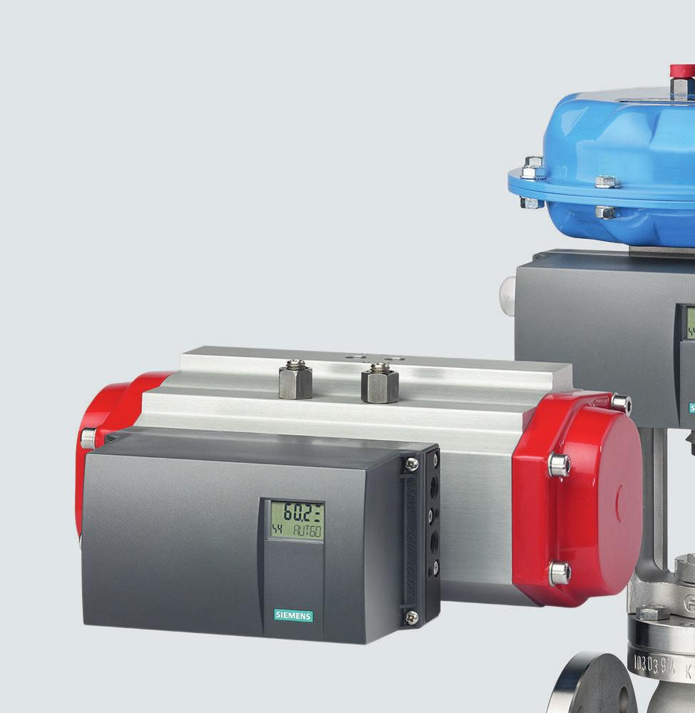
11 Introduction 1.5 Nameplates 3. Retain damaged parts for clarification. 4. Check the scope of delivery by comparing your order to the shipping documents for correctness and completeness. WARNING Using a damaged or incomplete device Risk of explosion in hazardous areas. Do not use damaged or incomplete devices. 1.5 Nameplates Layout of the nameplate 1 Manufacturer 8 Auxiliary power (supply air PZ) 2 Protection class 9 Software/hardware version 3 Consult operating instructions 10 Place of manufacture 4 Conformity with country-specific directives 11 Auxiliary power 5 Built-in option module 12 Ordering supplement (Order code) 6 QR code to the mobile website with device-specific information on the product 13 Article number 7 Serial number 14 Product name Figure 1-1 Nameplate layout, example Compact Operating Instructions, 05/2017, A5E AC 11
12 - - Introduction 1.6 Security information Layout of Ex nameplate F-Nr.: ARR P TÜV 11 ATEX X / 0518 IECEx TUN X / TÜV X II 2 G Ex d IIC T6/T4 Gb II 2 D Ex tb IIIC T100 C Db Ex td A21 IP66 T100 C CL.I, DIV.1, GP. ABCD CL.I, ZN.1, AEx d IIC CL.II, III, DIV.1, GP. EFG ZN.21, AEx tb IIIC T100 C Ta=85 C IP66 / Type 4X N1A S N : Technical data and temperature classes see certificate / operating instructions TÜV 12 ATEX X / IECEx TUN X / TÜV X II 2 G Ex ia IIC T4 Gb II 3 G Ex ic IIC T6/T4 Gc II 2 D Ex ia IIIC 110 C Db II 3 G Ex ec IIC T6/T4 Gc Ex td A21 IP66 T100 C - IS / 1 / AEx / Ex ib / IIC IS / I / A-G NI / 1 / 2 / A-D NI / 2 / AEx / Ex ec / IIC Before commissioning permanently Install per control Drawing A5E D - remove indications of the protection type which are not being used. -40 Ta +60 C(T6)/80 C(T4) 13-KB4BO S-XPL/ KB4BO-0105 XP, CL.I, DIV.1, GP.CD Ex d IIC DIP, CL.II, DIV.1, GP.EFG, CL.III, DIV.1-40 Ta +50(T6)/80(T4) C Technical data and temperature classes see certificate / operating instructions SEAL ALL CONDUITS WITHIN 18 INCHES 1 Approvals 3 FM/CSA marking for hazardous area 2 ATEX/IECEx marking for hazardous area 4 Permitted ambient temperature for the hazardous area of the corresponding temperature class Figure 1-2 Ex nameplate layout, example 1.6 Security information Siemens provides products and solutions with industrial security functions that support the secure operation of plants, systems, machines, and networks. In order to protect plants, systems, machines and networks against cyber threats, it is necessary to implement and continuously maintain a holistic, state-of-the-art industrial security concept. Siemens products and solutions only form one element of such a concept. Customer is responsible to prevent unauthorized access to its plants, systems, machines and networks. Systems, machines and components should only be connected to the enterprise network or the internet if and to the extent necessary and with appropriate security measures (e.g. use of firewalls and network segmentation) in place. Additionally, Siemens guidance on appropriate security measures should be taken into account. For more information about industrial security, please visit: Siemens products and solutions undergo continuous development to make them more secure. Siemens strongly recommends to apply product updates as soon as available and to always use the latest product versions. Use of product versions that are no longer supported, and failure to apply latest updates may increase customer s exposure to cyber threats. To stay informed about product updates, subscribe to the Siemens Industrial Security RSS Feed under 12 Compact Operating Instructions, 05/2017, A5E AC
13 Introduction 1.8 Notes on warranty 1.7 Transportation and storage To guarantee sufficient protection during transport and storage, observe the following: Keep the original packaging for subsequent transportation. Devices/replacement parts should be returned in their original packaging. If the original packaging is no longer available, ensure that all shipments are properly packaged to provide sufficient protection during transport. Siemens cannot assume liability for any costs associated with transportation damages. NOTICE Insufficient protection during storage The packaging only provides limited protection against moisture and infiltration. Provide additional packaging as necessary. Special conditions for storage and transportation of the device are listed in Technical data (Page 69). 1.8 Notes on warranty The contents of this manual shall not become part of or modify any prior or existing agreement, commitment or legal relationship. The sales contract contains all obligations on the part of Siemens as well as the complete and solely applicable warranty conditions. Any statements regarding device versions described in the manual do not create new warranties or modify the existing warranty. The content reflects the technical status at the time of publishing. Siemens reserves the right to make technical changes in the course of further development. Compact Operating Instructions, 05/2017, A5E AC 13
14 Introduction 1.8 Notes on warranty 14 Compact Operating Instructions, 05/2017, A5E AC

15 Safety instructions Precondition for use This device left the factory in good working condition. In order to maintain this status and to ensure safe operation of the device, observe these instructions and all the specifications relevant to safety. Observe the information and symbols on the device. Do not remove any information or symbols from the device. Always keep the information and symbols in a completely legible state. 2.2 Warning symbols on the device Symbol Meaning Consult operating instructions 2.3 Laws and directives Observe the safety rules, provisions and laws applicable in your country during connection, assembly and operation. These include, for example: National Electrical Code (NEC - NFPA 70) (USA) Canadian Electrical Code (CEC) (Canada) Further provisions for hazardous area applications are for example: IEC (international) EN (EC) Compact Operating Instructions, 05/2017, A5E AC 15

16 Safety instructions 2.5 Improper device modifications 2.4 Conformity with European directives The CE marking on the device shows conformity with the regulations of the following European guidelines: Electromagnetic compatibility EMC 2014/30/EU Atmosphère explosible ATEX 2014/34/EU Directive of the European Parliament and of the Council on the harmonization of the laws of the Member States relating to electromagnetic compatibility. Directive of the European Parliament and of the Council on the harmonization of the laws of the Member States relating to equipment and protective systems intended for use in potentially explosive atmospheres. The directives applied can be found in the EU declaration of conformity for the associated device. 2.5 Improper device modifications WARNING Improper device modifications Risk to personnel, system and environment can result from modifications to the device, particularly in hazardous areas. Only carry out modifications that are described in the instructions for the device. Failure to observe this requirement cancels the manufacturer's warranty and the product approvals. WARNING Improper modification on positioner 6DR5...6 Danger of explosion. The pneumatic terminal plate on the SIPART PS2 positioner 6DR5..6 is a safety-related component of the flameproof enclosure. Never loosen the screws 1 of the pneumatic terminal plate. Figure 2-1 Screws of the pneumatic terminal plate on the positioner 6DR Compact Operating Instructions, 05/2017, A5E AC
17 Safety instructions 2.6 Use in areas subject to explosion hazard 2.6 Use in areas subject to explosion hazard Qualified personnel for hazardous area applications Persons who install, connect, commission, operate, and service the device in a hazardous area must have the following specific qualifications: They are authorized, trained or instructed in operating and maintaining devices and systems according to the safety regulations for electrical circuits, high pressures, aggressive, and hazardous media. They are authorized, trained, or instructed in carrying out work on electrical circuits for hazardous systems. They are trained or instructed in maintenance and use of appropriate safety equipment according to the pertinent safety regulations. WARNING Use in hazardous areas Risk of explosion. Only use equipment that is approved for use in the intended hazardous area and labelled accordingly. See also Technical data (Page 69) WARNING Loss of safety of device with type of protection "Intrinsic safety Ex i" If the device has already been operated in non-intrinsically safe circuits or the electrical specifications have not been observed, the safety of the device is no longer ensured for use in hazardous areas. There is a risk of explosion. Connect the device with type of protection "Intrinsic safety" solely to an intrinsically safe circuit. Observe the specifications for the electrical data on the certificate and/or in Technical data (Page 69). Compact Operating Instructions, 05/2017, A5E AC 17
18 Safety instructions 2.6 Use in areas subject to explosion hazard 18 Compact Operating Instructions, 05/2017, A5E AC
19 Installing/mounting Basic safety instructions WARNING High operating force with pneumatic actuators Risk of injury when working on control valves due to the high operating force of the pneumatic actuator. Please observe the corresponding safety instructions for the pneumatic actuator in use. WARNING Lever for position detection Danger of crushing and shearing with mounting kits which use a lever for position detection. During commissioning and ongoing operation, severing or squeezing of limbs could occur as a result of the lever. Risk of injury when working on control valves due to the high operating force of the pneumatic actuator. Do not reach into the range of motion of the lever following mounting of the positioner and mounting kit. WARNING Impermissible accessories and spare parts Risk of explosion in areas subject to explosion hazard. Only use original accessories or original spare parts. Observe all relevant installation and safety instructions described in the instructions for the device or enclosed with the accessory or spare part. WARNING It is possible to damage the cover gasket If the cover gasket is not positioned correctly in the groove of the base plate, it could be damaged when the cover is mounted and screwed tight. Therefore make sure that the gasket is seated correctly. Compact Operating Instructions, 05/2017, A5E AC 19
20 Installing/mounting 3.1 Basic safety instructions WARNING Exceeded maximum permissible operating pressure Risk of injury or poisoning. The maximum permissible operating pressure depends on the device version, pressure limit and temperature rating. The device can be damaged if the operating pressure is exceeded. Hot, toxic and corrosive process media could be released. Ensure that maximum permissible operating pressure of the device is not exceeded. Refer to the information on the nameplate and/or in Technical data (Page 69). CAUTION Unsuitable compressed air Device damage. As a general rule, the positioner must only be operated with dry and clean compressed air. Use the customary water separators and filters. An additional dryer is required in extreme cases. Use dryers, especially if you operate the positioner at low ambient temperatures. CAUTION Please note the following before working on the control valve and when attaching the positioner Danger of injury. Prior to working on the control valve, you must move the control valve into a completely pressureless state. Proceed as follows: Depressurize the actuator chambers. Switch off the supply air PZ. Lock the valve in its position. Make sure that the valve has reached the pressureless state. If you interrupt the pneumatic auxiliary power to the positioner, the pressureless position may only be reached after a certain waiting time. When mounting, observe the following sequence imperatively to avoid injuries or mechanical damage to the positioner/mounting kit: Mount the positioner mechanically. Connect the electrical auxiliary power supply. Connect the pneumatic auxiliary power supply. Commission the positioner. 20 Compact Operating Instructions, 05/2017, A5E AC
21 Installing/mounting 3.1 Basic safety instructions WARNING Mechanical impact energy In order to ensure the degree of protection of the housing (IP66), protect the housing versions of the positioners listed here from mechanical impact energy: 6DR5..3; not greater than 2 Joule 6DR5..0; not greater than 1 Joule 6DR5..1 with inspection window; not greater than 1 Joule NOTICE Torque with NPT screwed gland Device damage. The maximum torque of the cable gland must not be exceeded. To avoid damage to the device, the NPT adapter must be held in place while the NPT gland is screwed into the NPT adapter. Refer to the section "Technical specifications > Construction (Page 70)" for the torque value Proper mounting NOTICE Incorrect mounting The device can be damaged, destroyed, or its functionality impaired through improper mounting. Before installing ensure there is no visible damage to the device. Make sure that process connectors are clean, and suitable gaskets and glands are used. Mount the device using suitable tools. Refer to the information in Construction (Page 70) for installation torque requirements. CAUTION Loss of type of protection Damage to device if the enclosure is open or not properly closed. The type of protection specified on the nameplate or in Technical data (Page 69) is no longer guaranteed. Make sure that the device is securely closed. Compact Operating Instructions, 05/2017, A5E AC 21
22 Installing/mounting 3.4 Using the positioner in a humid environment 3.2 Mounting the linear actuator For linear actuators, use the "linear actuator" mounting kit 6DR4004-8V or the integrated attachment. You require different installation parts depending on the selected actuator type. The mounting kit is suitable for a stroke of 3 to 35 mm. For a larger stroke range, you require a separately ordered lever 6DR4004-8L. Refer to the detailed operating instructions for further information on mounting. 3.3 Mounting the part-turn actuator You require an actuator-specific VDI/VDE 3845 mount to install the positioner on a part-turn actuator. You receive the mount and screws from the actuator manufacturer. Ensure that the mount has a sheet metal thickness of > 4 mm and reinforcements. You also need the mounting kit 6DR4004-8D or the stainless steel coupling TGX: Refer to the detailed operating instructions for further information on mounting. 3.4 Using the positioner in a humid environment Introduction The positioner enclosure provides IP66 protection with an intended installation position. It can therefore be operated in a moist or wet environment in the mounting positions shown below. Do not use other mounting positions since it would then be possible for liquids, fluff, fibers or dusts to enter the device via the exhaust openings. Favorable and unfavorable mounting positions Avoid the unfavorable mounting positions: To prevent fluids seeping through during normal operation of the device, e.g. through exhaust air openings. Otherwise the display becomes poorly legible. Figure 3-1 Favorable and unfavorable mounting positions 22 Compact Operating Instructions, 05/2017, A5E AC
23 Installing/mounting 3.5 Positioners subjected to fast acceleration or strong vibration Additional measures to prevent liquids from seeping through Take additional measures to prevent liquids from seeping through if the conditions force you to operate the positioner in an unfavorable mounting position. Additional measures required to prevent liquids from seeping through depend on the selected mounting position. You may also require: Gland with sealing ring, e.g. FESTO: CK - 1 / 4-PK-6 Approximately 20 to 30 cm plastic hose, e.g. FESTO: PUN - 8 x 1.25 SW Cable tie; the number and the length depend on the local conditions. Procedure 1. Install the casing such that rain water or condensate running along the pipes can be drained before the terminal strip of the positioner. 2. Check the seals of electrical connections for perfect fitting. 3. Check the seal in the enclosure cover for damage and contaminations. Clean and/or replace if required. 4. Install the positioner such that the sintered bronze attenuator at the bottom side of the enclosure points downwards in the vertical mounting position. If this is not possible, replace the attenuator with a suitable gland with a plastic hose. Procedure for installing the plastic hose on the gland 1. Unscrew the sintered bronze attenuator from the exhaust air opening at the bottom side of the enclosure. 2. Screw in the aforementioned gland into the exhaust air opening. 3. Install the aforementioned plastic hose into the gland and check whether it fits firmly. 4. Fasten the plastic hose with a cable tie onto the control valve such that the opening points downwards. 5. Ensure that the plastic hose does not have any kinks and the exhaust air flows out without any hindrance. 3.5 Positioners subjected to fast acceleration or strong vibration The electropneumatic positioner has an gear latch for the friction clutch and for the transmission ratio selector. Strong acceleration forces act on control valves that are subjected to heavy mechanical loads, e.g. breakaway valves, strongly shaking or vibrating valves, as well as in case of "vapor shocks". These forces may be much higher than the specified data. This may cause the friction clutch to move in extreme cases. The positioner is equipped with an gear latch for the friction clutch to counter these extreme cases. The setting of the transmission ratio selector can also be locked. Compact Operating Instructions, 05/2017, A5E AC 23
24 Installing/mounting 3.5 Positioners subjected to fast acceleration or strong vibration The locking procedure is illustrated and described below. Note Use of external NCS sensor / internal NCS module If you use the accessory part "NCS sensor for contactless position measurement" or a built-in internal NCS module, the locking and fixing measures described in this section are not necessary. Overview diagram NOTICE Wrong detection of the rotary or part-turn movement A different setting of the transmission ratio selector and the gear latch results in a hysteresis in position detection. The hysteresis in position detection can result in unstable control behavior of the higher level control loop. Make sure the transmission ratio selector 5 and the gear latch 1 are set to the same value, either to 33 or to Compact Operating Instructions, 05/2017, A5E AC
25 90 33 Installing/mounting 3.5 Positioners subjected to fast acceleration or strong vibration Gear latch 6 Friction clutch 2 Locking transmission ratio to 33 7 Friction clutch latch 3 Neutral position 8 Locking friction clutch 4 Locking transmission ratio to 90 9 Release friction clutch 5 Transmission ratio selector Figure 3-2 Locking friction clutch and transmission ratio Requirements The positioner is mounted. You know whether the transmission ratio is to be set to 33 or 90. The positioner has been commissioned successfully, i.e. initialization was completed with "FINISH". Compact Operating Instructions, 05/2017, A5E AC 25
26 Installing/mounting 3.6 Installing option modules Procedure NOTICE The following is applicable for the "flameproof enclosure" version: A friction clutch is provided on the outside of the positioner axis. Change the work area using this friction clutch. Do not open the flameproof enclosure of the positioner in explosion-prone atmospheres. Fix the setting acquired by initialization as follows: 1. Make sure the gear latch 1 is in neutral position 3. The neutral position is between 33 and Make sure the transmission ratio selector 5 is in the correct position. 3. Fix the transmission ratio with the gear latch 1. Turn the gear latch 1 with a standard approx. 4 mm wide screwdriver until the gear latch 1 locks. Turning right locks the transmission ratio to Turning left locks the transmission ratio to The transmission ratio is locked. Note Changing the setting of the transmission ratio selector The setting of the transmission ratio selector 5 can only be changed effectively if the gear latch 1 is in the neutral position To fix the friction clutch 6 insert a standard approx. 4 mm wide screwdriver in the friction clutch gear latch Use the screwdriver to turn the friction clutch gear latch 7 counterclockwise until it engages. The friction clutch 6 is locked. 3.6 Installing option modules A number of option modules are provided for the positioner. Different option modules are available depending on the version of the device. Only the available option modules are listed below. For additional information and the corresponding safety notes to be observed when installing the option modules, refer to the detailed operating instructions for your respective device version. Option modules in standard and intrinsically safe versions The following option modules are available: Position feedback module Alarm module SIA module Mechanical limit switch module 26 Compact Operating Instructions, 05/2017, A5E AC
27 Installing/mounting 3.6 Installing option modules EMC filter module NCS sensor Internal NCS module Option modules in "flameproof enclosure" version The following option modules are available: Position feedback module Alarm module Internal NCS module Internal NCS module The internal NCS module is used for wear-free position detection and is an optional equipment version in the positioner. The internal NCS module is installed as an alternative to position feedback module at the same slot in the positioner. Compact Operating Instructions, 05/2017, A5E AC 27
28 Installing/mounting 3.6 Installing option modules 28 Compact Operating Instructions, 05/2017, A5E AC
29 Connecting Basic safety instructions WARNING With intrinsically device version (Ex i) Risk of explosion in hazardous areas. For intrinsically safe device versions only the certified circuits may be connected as auxiliary power supply, control and signal circuits. Make sure that the power source of the used circuits is marked as intrinsically safe. WARNING Unsuitable cables, cable glands and/or plugs Risk of explosion in hazardous areas. Use only cable glands/plugs that comply with the requirements for the relevant type of protection. Tighten the cable glands in accordance with the torques specified in Technical data (Page 69). Close unused cable inlets for the electrical connections. When replacing cable glands use only cable glands of the same type. After installation check that the cables are seated firmly. See also Construction (Page 70) NOTICE Condensation in the device Damage to device through formation of condensation if the temperature difference between transportation or storage and the mounting location exceeds 20 C (36 F). Before taking the device into operation let the device adapt for several hours in the new environment. Compact Operating Instructions, 05/2017, A5E AC 29
30 Connecting 4.1 Basic safety instructions NOTICE Ambient temperature too high Damage to cable sheath. At an ambient temperature 60 C (140 F), use heat-resistant cables suitable for an ambient temperature at least 20 C (36 F) higher. WARNING Improper power supply Risk of explosion in hazardous areas as result of incorrect power supply, e.g. using direct current instead of alternating current. Connect the device in accordance with the specified power supply and signal circuits. The relevant specifications can be found in the certificates, in Technical data (Page 69) or on the nameplate. WARNING Unsafe extra-low voltage Risk of explosion in hazardous areas due to voltage flashover. Connect the device to an extra-low voltage with safe isolation (SELV). WARNING Lack of equipotential bonding Risk of explosion through compensating currents or ignition currents through lack of equipotential bonding. Ensure that the device is potentially equalized. Exception: It may be permissible to omit connection of the equipotential bonding for devices with type of protection "Intrinsic safety Ex i". WARNING Unprotected cable ends Risk of explosion through unprotected cable ends in hazardous areas. Protect unused cable ends in accordance with IEC/EN Compact Operating Instructions, 05/2017, A5E AC
31 Connecting 4.1 Basic safety instructions WARNING Improper laying of shielded cables Risk of explosion through compensating currents between hazardous area and the non hazardous area. Shielded cables that cross into hazardous areas should be grounded only at one end. If grounding is required at both ends, use an equipotential bonding conductor. WARNING Connecting device in energized state Risk of explosion in hazardous areas. Connect devices in hazardous areas only in a de-energized state. Exceptions: Devices having the type of protection "Intrinsic safety Ex i" may also be connected in energized state in hazardous areas. Exceptions for type of protection "Increased safety ec" (Zone 2) are regulated in the relevant certificate. WARNING Incorrect selection of type of protection Risk of explosion in areas subject to explosion hazard. This device is approved for several types of protection. 1. Decide in favor of one type of protection. 2. Connect the device in accordance with the selected type of protection. 3. In order to avoid incorrect use at a later point, make the types of protection that are not used permanently unrecognizable on the nameplate. NOTICE Standard cable gland/torque Device damage. Owing the reasons pertaining to tightness (IP enclosure rating) and the required tensile strength, only use the cables having a diameter 8 mm for standard M20x1.5 cable gland, or use a suitable seal insert in case of smaller diameters. In the NPT version, the positioner is delivered with a coupling. When inserting a counter piece in the coupling, ensure that the maximum permissible torque of 10 Nm is not exceeded. Compact Operating Instructions, 05/2017, A5E AC 31
32 Connecting 4.1 Basic safety instructions CAUTION Maximum AC/DC switching voltage with UL approval E The mechanical limit switch module 6DR4004-6K is approved for use for positioners with UL approval. The maximum supply voltage in this case is 30 V AC/DC. The mechanical limit switch module 6DR4004-8K is not approved for use for positioners with UL approval. If this information is ignored, the UL approval for the mechanical limit switch module for the positioner becomes invalid. Two-wire mode NOTICE Connection of voltage source to current input Device damage if a voltage source is connected to the current input I w (terminals 6 and 7). Never connect the current input I w to a voltage source, otherwise the positioner may be destroyed. Always use a voltage source with a maximum output current of I = 20 ma. Note Improvement of interference immunity Lay signal cables separate from cables with voltages > 60 V. Use cables with twisted wires. Keep device and cables at a distance from strong electromagnetic fields. Take account of the conditions for communication specified in the Technical data (Page 69). HART: Use shielded cables to guarantee the full specification according to HART. 32 Compact Operating Instructions, 05/2017, A5E AC
33 Connecting 4.1 Basic safety instructions Additional safety notes for PA and FF If the bus shield is fully effective, the interference immunity and the interference emission conform to the specifications. The following measures ensure that the bus shield is fully effective: The shields have been connected to the metallic connections of the positioner. The shields have been laid up to the terminal boxes, the distributor and the transceiver. Note Dissipation of glitch impulses/equipotential bonding In order to dissipate glitch impulses, the positioner must be connected to an equipotential bonding cable (earth potential) using a low resistance. The positioner in the Makrolon enclosure is therefore equipped with an additional cable. Connect the this cable to the shield of the bus cable and the equipotential bonding cable using a cable clamp. Devices in the stainless steel or aluminum enclosure have a corresponding terminal on the outer side of the enclosure. This terminal must also be connected to the equipotential bonding cable. For applications in hazardous areas, ensure an adequately suitable equipotential bonding between the hazardous and non-hazardous areas. The positioner is equipped with an additional input (terminal 81 [+] and terminal 82 [-]) to approach the safety position. After activating this function, this input must be continuously supplied with +24 V in order to retain the normal control function. If the 24-V signal is interrupted, the safety position is set as described in chapter "Pneumatic connection (Page 44)". Communication with the master is still possible. The "Jumper" on the basic electronics is used to activate this function. It can be accessed after removing the module cover, and must be switched from the right position (delivery state) to the left position. Compact Operating Instructions, 05/2017, A5E AC 33
34 Connecting 4.2 Electrical connection 4.2 Electrical connection SIPART PS2 with and without HART 1 Non-hazardous area 4 Binary input 1 2 Hazardous area 5 Signal source 3 Basic electronics 6 HART communicator Figure 4-1 Device version 2-wire 1 Non-hazardous area 4 Binary input 1 2 Hazardous area 5 Signal source 3 Basic electronics 6 HART communicator Figure 4-2 Device version 2/3/4-wire, with connection type 2-wire 34 Compact Operating Instructions, 05/2017, A5E AC
35 Connecting 4.2 Electrical connection 1 Non-hazardous area 5 Power source 2 Hazardous area 6 Signal source 3 Basic electronics 7 HART communicator 4 Binary input 1 Figure 4-3 Device version 2-/3-/4-wire, with wiring type 3-wire Basic electronics, 2/3/4-wire, with connection type 4-wire, connection diagram (with and without HART) 1 Non-hazardous area 5 Power source 2 Hazardous area 6 Signal source 3 Basic electronics 7 HART communicator 4 Binary input 1 Figure 4-4 Device version 2-/3-/4-wire, with wiring type 4-wire Compact Operating Instructions, 05/2017, A5E AC 35
36 Connecting 4.2 Electrical connection SIPART PS2 with PROFIBUS PA 1 Non-hazardous area 4 Input: Safety shutdown 2 Hazardous area 5 Binary input 1 3 Basic electronics 6 Signal source Figure 4-5 Device version with PROFIBUS PA SIPART PS2 with FOUNDATION Fieldbus 1 Non-hazardous area 4 Input: Safety shutdown 2 Hazardous area 5 Simulation enable 3 Basic electronics 6 Power source Figure 4-6 Device version with FOUNDATION Fieldbus 36 Compact Operating Instructions, 05/2017, A5E AC
37 Connecting 4.2 Electrical connection Split range For further information about "Split-range" operation, refer to the detailed operating instructions for your respective device version. Compact Operating Instructions, 05/2017, A5E AC 37
38 Connecting 4.2 Electrical connection Option modules Alarm modules 6DR4004-6A and -8A 1 Non-hazardous area 5 Fault message 2 Hazardous area 6 Limit 3 Alarm module 7 Switching amplifier 4 Binary input 2 8 Switching output Figure 4-7 Alarm module 38 Compact Operating Instructions, 05/2017, A5E AC
39 Connecting 4.2 Electrical connection Position feedback modules 6DR4004-6J and -8J U I U I Ex E I 1 Non-hazardous area 3 Position feedback module 2 Hazardous area 4 Feed splitter Figure 4-8 Position feedback module SIA modules 6DR4004-6G and -8G 1 Non-hazardous area 4 Fault message 2 Hazardous area 5 Limit 3 SIA module 6 Switching amplifier Figure 4-9 SIA module Compact Operating Instructions, 05/2017, A5E AC 39
40 Connecting 4.2 Electrical connection Mechanical limit switch modules 6DR4004-6K and -8K DANGER Supply with hazardous voltage When you supply the non-intrinsically safe version of the module with hazardous voltage, you must read the following safety rules before starting work on the device: 1. Isolate the device from power. Use a circuit breaker positioned near the device to do this. 2. Make sure that the device cannot be switched back on inadvertently. 3. Make sure the device is truly isolated from power. CAUTION Maximum AC/DC switching voltage with UL approval E The mechanical limit switch module 6DR4004-6K is approved for use for positioners with UL approval. The maximum supply voltage in this case is 30 V AC/DC. The mechanical limit switch module 6DR4004-8K is not approved for use for positioners with UL approval. If this information is ignored, the UL approval for the mechanical limit switch module for the positioner becomes invalid. 1 Non-hazardous area 5 Limit 2 Hazardous area 6 Switching amplifier 3 Mechanical limit switch module 7 Switching output 4 Fault message Figure 4-10 Mechanical limit switch module 40 Compact Operating Instructions, 05/2017, A5E AC
41 Connecting 4.2 Electrical connection Procedure 1. Loosen the screw 1 on the transparent cover Pull the transparent cover 2 up to the front end stop. 3. Tighten every cable in the corresponding terminal. 4. Slide the transparent cover 2 up to the end stop of the basic electronics. 5. Tighten the screw 1 of the transparent cover Connect the cables of each switch to the lug of the printed circuit board in pairs. Use the provided cable ties 3 for this purpose Screw Cover Cable tie Figure 4-11 Connecting the cables Option device version M12 connector This section describes which terminal of the devices and option modules listed below is connected with the respective pole of the M12 connector. Note Technical specifications Observe the specifications for the electrical data in the certificate and/or in section "Technical data (Page 69)". Compact Operating Instructions, 05/2017, A5E AC 41
42 Connecting 4.2 Electrical connection View of the mating side pole pattern Pole designation 1 Brown 4 Black 3 Blue 2 White Wire color of M12 connector M12 connector in basic device SIPART PS2 with and without HART You have a positioner 6DR R.. or 6DR S.. In this version of the positioner, the current input I W 4 to 20 ma of the basic electronics is connected via the M12 connector. Table 4-1 Assignment diagram Current input terminal Pole designation 6 (+) 1 - Brown Shield support of housing 4 - Black 7 and 8 (-) 3 - Blue M12 connector in basic device SIPART PS2 with PROFIBUS PA You have a positioner 6DR R.. or 6DR S. In this case the M12 connector is connected to the bus circuit of the basic electronics. Table 4-2 Assignment diagram Bus circuit terminal Pole designation Brown Shield support of housing 4 - Black Blue M12 connector in basic device SIPART PS2 with FOUNDATION Fieldbus You have a positioner 6DR R.. or 6DR S.. In this case the M12 connector is connected to the bus circuit of the basic electronics. Table 4-3 Assignment diagram Bus circuit terminal Pole designation Brown Shield support of housing 4 - Black Blue 42 Compact Operating Instructions, 05/2017, A5E AC
43 Connecting 4.2 Electrical connection M12 connector for connection of the outputs of the alarm module 6DR4004-6A / -8A (-Z D55) You have a positioner with order suffix -Z order code D55. In this version of the positioner, the M12 connector is used to electrically connect the current output of the position feedback module. Table 4-4 Assignment diagram Alarm output terminal Pole designation 41 (+) 1 - Brown 52 (-) 4 - Black 42 (-) 3 - Blue 51 (+) 2 - White M12 connector for connecting the outputs of the position feedback module 6DR4004-6J / 8J (-Z D53) You have a positioner with order suffix -Z order code D53. In this version of the positioner, the M12 connector is used to electrically connect the current output of the position feedback module. Table 4-5 Assignment diagram Current output terminal Pole designation 61 (+) 1 - Brown Shield support of housing 4 - Black 62 (-) 3 - Blue M12 connector for connecting the external position detection system (-Z D54) You have a positioner with order suffix -Z order code D54. In this version of the positioner, the M12 connector is used to electrically connect the fitted EMC filter module (C73451 A430 D23). Connect the external position detection system using the M12 connector. Table 4-6 Assignment diagram Terminal POS (X1/2) VCC (X1/4) GND (X1/1) VREF (X1/3) Pole designation 3 - Blue 1 - Brown 4 - Black 2 - White Compact Operating Instructions, 05/2017, A5E AC 43
44 Connecting 4.3 Pneumatic connection M12 connector for connecting the outputs of the SIA module 6DR4004-6G /-8G (-Z D56) You have a positioner with order suffix -Z order code D56. In this version of the positioner, the M12 connector is used to electrically connect the outputs of the SIA module. Table 4-7 Assignment diagram Alarm output terminal Pole designation 41 (+) 1 - Brown 52 (-) 4 - Black 42 (-) 3 - Blue 51 (+) 2 - White 4.3 Pneumatic connection WARNING Pneumatic auxiliary power Owing to safety reasons, the pneumatic auxiliary power supply must be fed after installation only if the positioner is switched to the "P-manual mode" when an electrical signal is available, refer to the as-delivered condition. Note Specifications regarding air quality Observe the specifications regarding the air quality, see section "Technical specifications > Pneumatic data (Page 70)". If required, connect the pressure gauge block for supply air and actuating pressure. Connection via female thread G¼ or ¼" NPT: Y1: actuating pressure 1 for single and double-acting actuators Y2: actuating pressure 2 for double-acting actuators Exhaust air outlet with a sound absorber. Remove the sound absorber if required. 44 Compact Operating Instructions, 05/2017, A5E AC
45 Connecting 4.3 Pneumatic connection For double-acting actuators, connect actuating pressure Y1 or Y2 depending on the desired safety setting. Safety position in case of electrical auxiliary power supply failure: Positioner with single-acting pneumatic system: Y1 depressurized Positioner with double-acting pneumatic system: Y1 pressurized (maximum actuating pressure), Y2 depressurized Positioner with Fail in Place pneumatic system: Hold Y1 and Y2 (current actuating pressure) Note Leakage Besides continuous air consumption, a leakage can cause the positioner to try to compensate the position deviation. This will result in premature wear in the entire control device. After installing the pneumatic connections, check the tightness of the entire control valve Pneumatic connection for 6DR5..0/1/2/3 Structure The pneumatic connections are provided on the right side of the positioner Actuating pressure Y1 for single and double-acting actuators Positioner shaft Supply air PZ Actuating pressure Y2 for double-acting actuators Exhaust air outlet with a sound absorber Figure 4-12 Pneumatic connection on the standard controller Compact Operating Instructions, 05/2017, A5E AC 45
Compact Operating Instructions SIPART PS2 (6DR5...) Electropneumatic positioners.
 Electropneumatic positioners.") Compact Operating Instructions Electropneumatic positioners EDITION 05/2018 www.siemens.com Introduction 1 Safety instructions 2 SIPART Electropneumatic positioners Compact Operating Instructions Installing/mounting
Compact Operating Instructions Electropneumatic positioners EDITION 05/2018 www.siemens.com Introduction 1 Safety instructions 2 SIPART Electropneumatic positioners Compact Operating Instructions Installing/mounting
SIPART PS2. Smart Valve Positioner. Venting Gauge Block. Installation Instructions. Answers for industry.
 SIPART PS2 Smart Valve Positioner Venting Gauge Block Installation Instructions Edition 12/2014 Answers for industry. Introduction 1 Safety notes 2 SIPART PS2 Smart Valve Positioner Venting Gauge Block
Operating Instructions SIPART. Electropneumatic positioners SIPART PS2 with PROFIBUS PA. Edition 10/2013. Answers for industry.
 SIPART Electropneumatic positioners Operating Instructions Edition 10/2013 Answers for industry. Introduction 1 Safety information 2 SIPART Electropneumatic positioner Operating Instructions Description
SIPART. Electropneumatic positioners SIPART PS2 with and without HART. Operating Instructions. Answers for industry.
 SIPART Electropneumatic positioners Operating Instructions Edition 06/2013 Answers for industry. 2B Introduction 1 Safety information 2 SIPART Electropneumatic positioners SIPART PS2 with and without
Refer to attachment for more details. Andreas Meyer
 IECEx Certificate of Conformity INTERNATIONAL ELECTROTECHNICAL COMMISSION IEC Certification Scheme for Explosive Atmospheres for rules and details of the IECEx Scheme visit www.iecex.com Certificate No.:
SIPART PS2. Smart Valve Positioner. Integral Volume Booster. Installation Instructions. Answers for industry.
 SIPART PS2 Smart Valve Positioner Integral Volume Booster Installation Instructions Edition 10/2014 Answers for industry. Introduction 1 Safety notes 2 SIPART PS2 Smart Valve Positioner Integral Volume
SIPART PS2. Smart Valve Positioner. Integral Volume Booster. Installation Instructions. Answers for industry.
 SIPART PS2 Smart Valve Positioner Integral Volume Booster Installation Instructions Edition 4/2015 Answers for industry. Introduction 1 Safety notes 2 SIPART PS2 Smart Valve Positioner Integral Volume
SIPART PS2. Smart Valve Positioner. Integral Volume Booster. Installation Instructions. Answers for industry.
 SIPART PS2 Smart Valve Positioner Integral Volume Booster Installation Instructions Edition 11/2014 Answers for industry. Introduction 1 Safety notes 2 SIPART PS2 Smart Valve Positioner Integral Volume
Temperature transmitters SITRANS TF, HART. Operating instructions July 2012 SITRANS. Answers for industry.
 Temperature transmitters SITRANS TF, HART Operating instructions July 2012 SITRANS Answers for industry. Introduction 1 Safety information 2 SITRANS Temperature transmitter Operating Instructions Description
dv/dt filter compact plus Voltage Peak Limiter SINAMICS SINAMICS G120P dv/dt filter compact plus Voltage Peak Limiter Safety information 1 General 2
 dv/dt filter compact plus Voltage Peak Limiter SINAMICS SINAMICS G120P dv/dt filter compact plus Voltage Peak Limiter Operating Instructions Safety information 1 General 2 Mechanical installation 3 Electrical
Line reactors SINAMICS. SINAMICS G130 Line reactors. Safety information 1. General. Mechanical installation 3. Electrical installation
 Safety information 1 General 2 SINAMICS SINAMICS G130 Mechanical installation 3 Electrical installation 4 Technical specifications 5 Operating Instructions Control version V4.7 04/2014 A5E00331462A Legal
Series 3730 Type Electropneumatic Positioner
 Series 3730 Type 3730-0 Electropneumatic Positioner Application Single-acting or double-acting positioner for attachment to pneumatic control valves Set point Travel 4 to 20 ma 5.3 to 200 mm The positioner
SINAMICS G130. Terminal Module 150 (TM150) Operating Instructions 03/2013 SINAMICS
 Operating Instructions 03/2013 SINAMICS") SINAMICS G130 Operating Instructions 03/2013 SINAMICS s Safety information 1 General information 2 SINAMICS SINAMICS G130 Mechanical installation 3 Electrical installation 4 Technical specifications 5
SINAMICS G130 Operating Instructions 03/2013 SINAMICS s Safety information 1 General information 2 SINAMICS SINAMICS G130 Mechanical installation 3 Electrical installation 4 Technical specifications 5
MANUAL Surge Protectors
 PROCESS AUTOMATION MANUAL Surge Protectors DP-LBF-I1.36.DE and DP-LBF- I1.36.IE With regard to the supply of products, the current issue of the following document is applicable: The General Terms of Delivery
Industrial Controls. Motor management and control devices SIMOCODE pro - Application examples. Introduction 1. Application example
 Introduction 1 Application example 2 Industrial Controls Motor management and control devices SIMOCODE pro - Application examples Application Manual Example circuits control functions 3 Further application
Explosion-Protected Arc-Fault Protection ExAFCI Arc-Fault Circuit Interrupter
 Installation, Operation & Maintenance Sheet Explosion-Protected Arc-Fault Protection ExAFCI Arc-Fault Circuit Interrupter > Contents 1 Contents 1 Contents...2 2 General Information...2 2.1 Manufacturer...2
Line reactors SINAMICS. SINAMICS G120P Line reactors. Safety information 1. General. Mechanical installation 3. Electrical installation 4
 Safety information 1 General 2 SINAMICS SINAMICS G120P Mechanical installation 3 Electrical installation 4 Technical specifications 5 Operating Instructions Control version V4.6 11/2013 A5E32845290B AA
SITOP power supply. Selectivity modules. Overview. Safety notes. Description, device design, dimension drawing. Mounting/removal 3
 Overview Safety notes 1 SITOP power supply Manual Description, device design, dimension drawing 2 Mounting/removal 3 Mounting position, mounting clearances 4 Installation 5 Technical data 6 Safety, approvals,
Siemens Drives & PLCs
 Automation System S7-300: Getting Started CPU 31xC: Commissioning Introduction 1 Preparation 2 SIMATIC S7-300 Automation System S7-300: Getting Started CPU 31xC: Commissioning Learning units 3 Further
YT-870 / 875 Series. Rotork YTC Limited VERSION 1.06
 PRODUCT MANUAL Rotork YTC Limited VERSION 1.06 Contents 1 Introduction... 3 1.1 General Information for the users... 3 1.2 Manufacturer Warranty... 3 1.3 Explosion Proof Warning... 4 2 Product Description...
Operating Instructions (Translation) 3. Safety Information. 1. Description. 2. Explosion Protection. Supply module Type 17-21BB-170x
 3. Safety Information. 1. Description. 2. Explosion Protection. Supply module Type 17-21BB-170x") 1. Description The supply module was developed specially for direct mounting in hazardous areas in Zone 1 and 21 and is ATEX-certified. The supply module is a permanently installed piece of electrical
1. Description The supply module was developed specially for direct mounting in hazardous areas in Zone 1 and 21 and is ATEX-certified. The supply module is a permanently installed piece of electrical
SIMATIC. Process Control System PCS 7 Configuration McAfee Endpoint Security Security information 1. Preface 2.
 Security information 1 Preface 2 SIMATIC Configuration 3 Process Control System PCS 7 Configuration McAfee Endpoint Security 10.5 Installation Manual 03/2018 A5E44395618-AA Legal information Warning notice
SolConeX extra-low voltage flange socket
 SolConeX extra-low voltage flange socket Operating instructions Additional languages www.stahl-ex.com Contents 1 General Information...3 1.1 Manufacturer...3 1.2 Information regarding the operating instructions...3
FLEX Ex Spring Clamp Terminal Base
 Installation Instructions FLEX Ex Spring Clamp Terminal Base (Cat. No. 1797-TB3S) 1 10 11 4 Only remove this cover plug if connecting another terminal base unit. 3 5 6 12 2 7 8 9 41253 Component Identification
SIMATIC Ident RFID systems MDS D423 Compact Operating Instructions
 SIMATIC Ident RFID systems Compact Operating Instructions Legal information Warning notice system This manual contains notices you have to observe in order to ensure your personal safety, as well as to
SINAMICS. SINAMICS G120P dv/dt filter plus Voltage Peak Limiter. Safety information 1. General. Mechanical installation. Electrical installation 4
 Safety information 1 General 2 SINAMICS SINAMICS G120P dv/dt filter plus Voltage Peak Limiter Operating Instructions Mechanical installation 3 Electrical installation 4 Maintenance and servicing 5 Technical
Series 3730 Electropneumatic Positioner Type
 Series 3730 Electropneumatic Positioner Type 3730-0 Application Single-acting or double-acting positioner for attachment to pneumatic control valves Reference variable Travels 4 to 20 ma 5.3 to 200 mm
SINAMICS G130. Voltage Sensing Module 10 (VSM10) Operating Instructions 05/2010 SINAMICS
 Operating Instructions 05/2010 SINAMICS") SINAMICS G130 Operating Instructions 05/2010 SINAMICS s Safety information 1 General 2 SINAMICS SINAMICS G130 Voltage Sensing Module 10 (VSM10) Mechanical installation 3 Electrical installation 4 Technical
SINAMICS G130 Operating Instructions 05/2010 SINAMICS s Safety information 1 General 2 SINAMICS SINAMICS G130 Voltage Sensing Module 10 (VSM10) Mechanical installation 3 Electrical installation 4 Technical
SINAMICS G130. Voltage Sensing Module 10 (VSM10) Operating instructions 03/2011 SINAMICS
 Operating instructions 03/2011 SINAMICS") SINAMICS G130 Operating instructions 03/2011 SINAMICS s Safety information 1 General 2 SINAMICS SINAMICS G130 Voltage Sensing Module 10 (VSM10) Mechanical installation 3 Electrical installation 4 Technical
SINAMICS G130 Operating instructions 03/2011 SINAMICS s Safety information 1 General 2 SINAMICS SINAMICS G130 Voltage Sensing Module 10 (VSM10) Mechanical installation 3 Electrical installation 4 Technical
Product Information Mixed. Configuration ET 200SP / ET 200AL SIMATIC. ET 200SP Product Information Mixed Configuration ET 200SP / ET 200AL.
 Product Information Mixed Configuration ET 200SP / ET 200AL SIMATIC ET 200SP Product Information Mixed Configuration ET 200SP / ET 200AL Product Information Preface Application planning 1 Mounting 2 Connection
PanelView Plus/VersaView CE Terminals and Display Modules
 Installation Instructions PanelView Plus/VersaView CE Terminals and Display Modules (Catalog Numbers 2711P-xxxxxx, 6182H-xxxxxx) English Inside: Overview...2 For More Information...2 Modular Components...3
Use with 0 to 70 C ambient. temperature SIMATIC. Process Control System PCS 7 Use with 0 to 70 C ambient temperature. Preface 1. Product combination 2
 Use with 0 to 70 C ambient temperature SIMATIC Preface 1 Product combination 2 Product family 3 Process Control System PCS 7 Use with 0 to 70 C ambient temperature System Manual 02/2015 A5E35458345-AA
Pneumatic Control/Feedback
 897 /Feedback Type 897 can be combined with... Compact design Integrated pilot valve with manual override Internal control air routing Automatic end position adjustment With ATEX II cat. G/D and cat. D/G
SIWAREX JB Aluminum Housing. Instruction Manual Edition 03/2006
 s SIWAREX JB Aluminum Housing Instruction Manual Edition 03/2006 Table of Contents Table of Contents... 2 Warning and Safety Terms... 3 General... 4 1 Technical Description... 5 1.1 Area of Application...
Pneumatic Control/Feedback
 897 /Feedback Type 897 can be combined with... Compact design Integrated pilot valve with manual override Internal control air routing Bright LED position indicator Automatic end position adjustment Type
Operating instructions. Speed monitor D / / 2014
 Operating instructions Speed monitor D200 80005257 / 00 05 / 2014 Contents 1 Preliminary note...4 1.1 Symbols used...4 1.2 Warning signs used...4 2 Safety instructions...5 2.1 General...5 2.2 Target group...5
SITRANS TF with and without HART SITRANS. Temperature transmitter SITRANS TF with and without HART. Introduction 1. Safety information.
 Introduction 1 Safety information 2 SITRANS Temperature transmitter SITRANS TF with and without HART Operating Instructions Description 3 Installing/mounting 4 Connecting 5 Operation 6 Functional safety
Line filter SINAMICS. SINAMICS G130 Line filter. Safety information 1. General 2. Mechanical installation 3. Electrical installation 4
 Safety information 1 General 2 SINAMICS SINAMICS G130 Mechanical installation 3 Electrical installation 4 Technical specifications 5 Operating Instructions Control version V4.8 07/2016 A5E00331460A Legal
Do not open when energized or when an explosive atmosphere is present. Electrostatic hazard, clean only with damp cloth.
 D460/D470 Series - ATEX certified position transmitter nnnn II 2 GD ITS 11 ATEX 17431X Ex d IIC T* Gb Tamb -*ºC to +*ºC Ex tb IIIC T* Db Tamb -*ºC to +*ºC IP6X Ambient variation -60 C to +110 C (T4/T130
SMARTLINE RM76 Supplementary instructions
 SMARTLINE RM76 Supplementary instructions 2-wire / Guided Radar (TDR) Level Meter Supplementary Instructions for ATEX applications CONTENTS SMARTLINE RM76 1 General safety information 5 1.1 Scope of the
Operating Instructions (Compact) SIMATIC. Industrial PC SIMATIC Microbox PC 420. Siemens. Release 11/2006 A5E
 SIMATIC. Industrial PC SIMATIC Microbox PC 420. Siemens. Release 11/2006 A5E") Operating Instructions (Compact) 1 SIMATIC Industrial PC Release 11/2006 A5E00344128-04 Siemens Safety Guidelines This manual contains notices you have to observe in order to ensure your personal safety,
Operating Instructions (Compact) 1 SIMATIC Industrial PC Release 11/2006 A5E00344128-04 Siemens Safety Guidelines This manual contains notices you have to observe in order to ensure your personal safety,
ET 200S distributed I/O system 4DO DC24V/2A ST digital electronic module (6ES7132-4BD32-0AA0)
") 4DO DC24V/2A ST digital electronic module (6ES7132-4BD32- SIMATIC Preface 1 Properties 2 Diagnostics 3 ET 200S distributed I/O system 4DO DC24V/2A ST digital electronic module (6ES7132-4BD32- Manual 10/2015
4DO DC24V/2A ST digital electronic module (6ES7132-4BD32- SIMATIC Preface 1 Properties 2 Diagnostics 3 ET 200S distributed I/O system 4DO DC24V/2A ST digital electronic module (6ES7132-4BD32- Manual 10/2015
IO-Link Master (6ES7147-4JD00-0AB0) SIMATIC. ET 200pro IO-Link Master (6ES7147-4JD00-0AB0) Preface. Documentation guide. Product overview.
 SIMATIC. ET 200pro IO-Link Master (6ES7147-4JD00-0AB0) Preface. Documentation guide. Product overview.") IO-Link Master (6ES7147-4JD00-0AB0) SIMATIC ET 200pro IO-Link Master (6ES7147-4JD00-0AB0) Manual Preface Documentation guide 1 Product overview 2 Wiring 3 Parameters/address space 4 Diagnostics alarms
IO-Link Master (6ES7147-4JD00-0AB0) SIMATIC ET 200pro IO-Link Master (6ES7147-4JD00-0AB0) Manual Preface Documentation guide 1 Product overview 2 Wiring 3 Parameters/address space 4 Diagnostics alarms
ET 200S distributed I/O Digital electronic module 2DO AC V (6ES7132-4FB01-0AB0)
") SIMATIC ET 200S distributed I/O SIMATIC Preface ET 200S distributed I/O Digital electronic module 2DO AC24..230V (6ES7132-4FB01-0AB0) Properties 1 Parameters 2 Diagnostics 3 Manual 04/2007 A5E01077264-01
SIMATIC ET 200S distributed I/O SIMATIC Preface ET 200S distributed I/O Digital electronic module 2DO AC24..230V (6ES7132-4FB01-0AB0) Properties 1 Parameters 2 Diagnostics 3 Manual 04/2007 A5E01077264-01
Operating Manual / IEC. Explosion-Proofed Junction Boxes, Polyester. Wallücker Bahndamm 7 DE Kirchlengern
 Operating Manual / IEC Explosion-Proofed Junction Boxes, Polyester Wallücker Bahndamm 7 DE- 32278 Kirchlengern Tel.: +49 5223 49107-0 Fax: +49 5223 49107-28 info@multi-box.com www.multi-box.com Contents
Get to know our positioner! One that masters everything: SIPART PS2. Flexibility for all challenges. siemens.com/positioner
 Get to know our positioner! One that masters everything: SIPART PS2 Flexibility for all challenges siemens.com/positioner The proven multi-talent SIPART PS2 SIPART PS2 is currently the most widely used
SIMATIC. Industrial PC Microsoft Windows 7 (USB stick) Safety instructions 1. Initial startup: Commissioning the operating system
 Safety instructions 1. Initial startup: Commissioning the operating system") Safety instructions 1 Initial startup: Commissioning the operating system 2 SIMATIC Industrial PC Operating Instructions Restoring the factory settings of the operating system and partitions(restore) 3
Safety instructions 1 Initial startup: Commissioning the operating system 2 SIMATIC Industrial PC Operating Instructions Restoring the factory settings of the operating system and partitions(restore) 3
Operating Instructions
 Introduction To protect the signal lines of field devices and systems in the cabinet against lightning. Pepperl+Fuchs covers the complete range of Surge Protection Barriers. Housing types Depending on
Readme SiVArc V14 SP1 Update 6
 Product version 1 Improvements in Update 6 2 Readme 05/2018 Legal information Warning notice system This manual contains notices you have to observe in order to ensure your personal safety, as well as
SIMATIC. Process Control System PCS 7 Advanced Process Functions Operator Manual. Preface. Security information 1. Overview 2. Material management 3
 Preface Security information 1 SIMATIC Process Control System PCS 7 Advanced Process Functions Operator Manual Operating Manual Overview 2 Material management 3 Material lot management 4 Storage location
SIWAREX JB stainless steel with ATEX. certificate. Weighing systems. SIWAREX JB stainless steel with ATEX certificate.
 SIWAREX JB stainless steel with ATEX certificate Introduction 1 Notes on handling the product 2 Weighing systems SIWAREX JB stainless steel with ATEX certificate Compact Operating Instructions Description
SIMATIC. Industrial PC Microsoft Windows 7. Safety instructions 1. Initial startup: Commissioning the operating. system
 Safety instructions 1 Initial startup: Commissioning the operating 2 system SIMATIC Industrial PC Operating Instructions Restoring the factory settings of the operating system and 3 partitions (Restore)
PI-EX-ME-2NAM/COC-24VDC
 Ex-i NAMUR Isolation Amplifier, With Intrinsically Safe Input and Relay Output, PDT, Two-Channel, 4 V DC Supply INTERFACE Data Sheet 0033_0_en PHOENIX CONTACT - /007 Description The PI-EX-ME-NAM/COC-4VDC
High-precision valve control using intelligent positioners. sipart
 High-precision valve control using intelligent positioners sipart The SIPART PS2 electropneumatic positioner is number 1 in its field by a very wide margin. Our past experience gathered from 15 years in
English. Operating Manual. Conductive point level switch MLR120. Retain for later reference. Companies / brands of GHM
 English Operating Manual Conductive point level switch MLR120 Companies / brands of GHM www.ghm-group.de Retain for later reference Table of contents Page 1. Proper use (application areas)... 3 Safety
DR7100 SERIES Supplementary instructions
 DR700 SERIES Supplementary instructions Guided Radar (TDR) Level Instrument for 2-wire control systems Supplementary Instructions for ATEX applications AMETEK Drexelbrook - EDO -0-2, DR700-LM ATEX, Issue
PHOENIX CONTACT - 12/2007
 Ex-i NAMUR Isolation Amplifier, With Intrinsically Safe Input and Active Transistor Output, Two-Channel INTERFACE Data Sheet 0943_00_en PHOENIX CONTACT - /007 Description The PI-EX-ME-NAM/TO-A is a two-channel
PI-EX-ME-2NAM/COC-120VAC
 PI-EX-ME-NAM/COC-0VAC Ex-i NAMUR Isolation Amplifier, With Intrinsically Safe Input and Relay Output, PDT, Two-Channel, 0 V AC Supply INTERFACE Data Sheet 0944_00_en PHOENIX CONTACT - 0/008 Description
SIMATIC. ET 200S distributed I/O Digital electronic module 4DO DC24V/0.5 A ST (6ES7132-4BD01-0AA0) Preface. Properties 1. Diagnostics 2.
 Preface. Properties 1. Diagnostics 2.") SIMATIC ET 200S distributed I/O Digital electronic module 4DO DC24V/0.5 A ST (6ES7132-4BD01- SIMATIC Preface Properties 1 Diagnostics 2 ET 200S distributed I/O Digital electronic module 4DO DC24V/0.5 A
SIMATIC ET 200S distributed I/O Digital electronic module 4DO DC24V/0.5 A ST (6ES7132-4BD01- SIMATIC Preface Properties 1 Diagnostics 2 ET 200S distributed I/O Digital electronic module 4DO DC24V/0.5 A
DANGER indicates that death or severe personal injury will result if proper precautions are not taken.
 Preface SIMATIC ET 200S distributed I/O Digital electronic module 2RO NO/NC DC24..48V/5A AC24..230V/5A (6ES7132-4HB50-0AB0) SIMATIC ET 200S distributed I/O Digital electronic module 2RO NO/NC DC24..48V/5A
RAD-DO8-IFS. I/O extension module, eight digital transistor outputs. Data sheet. 1 Description
 I/O extension module, eight digital transistor outputs Data sheet 105364_en_00 PHOENIX CONTACT 2013-03-26 1 Description The I/O extension module can be used in conjunction with Radioline wireless modules
Resistance thermometer With spring-loaded tip Model TR55
 Temperature Resistance thermometer With spring-loaded tip Model TR55 WIKA data sheet TE 60.55 for further approvals see page 2 Applications Bearing temperature measurement on: Pumps Gears Motors Special
97105 Inline 3/2, 5/2 & 5/3 way spool valves electromagnetic actuated, indirectly controlled G1/4, 1/4 NPT, G1/2, 1/2 NPT
 70 Inline 3/, / & /3 way spool valves electromagnetic actuated, indirectly controlled G/, / NPT, G/, / NPT Main application: single and double operated actuators TÜV-approval based on type examination
PTB 01 ATEX Example / Beispiel / Exemple. Type Operating Instructions
 Device with II 2G EX i approval Geräte mit II 2G EX i Zulassung Appareils avec mode de protection II 2G EX i Example / Beispiel / Exemple Type 6106 Operating Instructions Bedienungsanleitung Manuel d utilisation
Series 3730 Type Electropneumatic Positioner
 Series 3730 Type 3730- Electropneumatic Positioner Application Single-acting or double-acting positioner for attachment to pneumatic control valves. Self-calibrating, automatic adaptation to valve and
PROFIBUS-PA Positioner Type 3785
 PROFIBUS-PA Positioner Type 3785 Application Single-acting or double-acting PROFIBUS-PA positioner for attachment to pneumatic control valves. Rated travel from 7.5 to 120 mm Opening angle up to 120 Smart,
Description. SIMATIC Sensors. RF systems Wide-range power supply unit for SIMATIC RF systems. Operating Instructions 11/2007 J31069-D0169-U001-A4-7618
 1 SIMATIC Sensors RF systems Wide-range power supply unit for SIMATIC RF systems Operating Instructions 11/2007 J31069-D0169-U001-A4-7618 Safety Guidelines This manual contains notices you have to observe
Supplementary Components WirelessHART products
 Overview SITRANS AW200 WirelessHART adapter The SITRANS AW200 WirelessHART adapter is a batterypowered communication component, which integrates HART and 4 to 20 ma field devices into a WirelessHART network.
SIMATIC. ET 200S distributed I/O Digital electronic module 4DO DC24V/0.5A ST (6ES7132-4BD02-0AA0) Preface. Properties 2. Diagnostics 3.
 Preface. Properties 2. Diagnostics 3.") Preface 1 Properties 2 SIMATIC Diagnostics 3 ET 200S distributed I/O Digital electronic module 4DO DC24V/0.5A ST (6ES7132-4BD02- Manual 01/2008 A5E01254028-01 Safety Guidelines This manual contains notices
Preface 1 Properties 2 SIMATIC Diagnostics 3 ET 200S distributed I/O Digital electronic module 4DO DC24V/0.5A ST (6ES7132-4BD02- Manual 01/2008 A5E01254028-01 Safety Guidelines This manual contains notices
PHOENIX CONTACT - 05/2007
 Ex Universal Module Carrier (Motherboard) for Accommodating 3-Wire Measuring Transducers, Intrinsically Safe, for a Maximum of 8 PI Ex Modules INTERFACE Data Sheet 103030_00_en PHOENIX CONTACT - 05/2007
T EN TROVIS Electropneumatic Positioner
 T 8484-1 EN TROVIS 3730-1 Electropneumatic Positioner Application Single-acting positioner for attachment to pneumatic globe and rotary valves. Self-calibrating, automatic adaptation to valve and actuator.
SolConeX Wall-Mounted Socket, 16 A
 SolConeX Wall-Mounted Socket, 16 A Operating instructions Additional languages www.stahl-ex.com General Information Contents 1 General Information...2 1.1 Manufacturer...2 1.2 Information Regarding the
SIMATIC. S7-1500/ET 200MP DI 16x230VAC BA Digital Input Module (6ES7521-1FH00-0AA0) Preface. Documentation guide. Product overview.
 Preface. Documentation guide. Product overview.") Preface Documentation guide 1 SIMATIC S7-1500/ET 200MP DI 16x230VAC BA Digital Input Module (6ES7521-1FH00-0AA0) Manual Product overview 2 Wiring 3 Address space 4 Diagnostic alarms 5 Technical specifications
Preface Documentation guide 1 SIMATIC S7-1500/ET 200MP DI 16x230VAC BA Digital Input Module (6ES7521-1FH00-0AA0) Manual Product overview 2 Wiring 3 Address space 4 Diagnostic alarms 5 Technical specifications
Operating instructions. Switching amplifier DN0210 DN / / 2015
 Operating instructions Switching amplifier DN0210 DN0220 UK 80011079 / 00 01 / 2015 Contents 1 Preliminary note...4 1.1 Symbols used...4 1.2 Warning signs used...4 2 Safety instructions...5 2.1 General...5
Siemens Industrial SIMATIC. Process Control System PCS 7 Configuration Trend Micro OfficeScan Server XG. Security information 1.
 Security information 1 Preface 2 SIMATIC Configuration 3 Process Control System PCS 7 Configuration Trend Micro OfficeScan Server XG Commissioning Manual Siemens Industrial 03/2018 A5E44395601-AA Legal
Series 3731 Type Electropneumatic Ex d Positioner with FOUNDATION TM fieldbus communication
 Series 3731 Type 3731-5 Electropneumatic Ex d Positioner with FOUNDATION TM fieldbus communication Application Positioners for attachment to pneumatic control valves Rated travels from 3.6 to 200 mm Opening
SIMATIC. Process Control System PCS 7 Configuration Symantec Endpoint Protection V14. Security information 1. Preface 2.
 Security information 1 Preface 2 SIMATIC Configuration 3 Process Control System PCS 7 Configuration Symantec Endpoint Protection V14 Commissioning Manual 03/2018 A5E44395521-AA Legal information Warning
Siemens Spares. Preface 1. Scope of Delivery 2 SIPLUS CMS4000. Product Characteristics 3 ION PROFIBUS DP SPY T001 Installation and Maintenance 4
 Preface 1 Scope of Delivery 2 Product Characteristics 3 Industrial I/O-Node ION PROFIBUS DP SPY T001 Installation and Maintenance 4 6AT8000-1BA00-5XA0 Notes on the CE Mark 5 References 6 Appendix 7 Release
BaseUnits (6ES7193-6BP.../3RK1908-0AP00 ) SIMATIC. ET 200SP BaseUnits. Preface. Guide to the documentation 1. Product overview 2
 SIMATIC. ET 200SP BaseUnits. Preface. Guide to the documentation 1. Product overview 2") BaseUnits (6ES7193-6BP.../3RK1908-0AP00 ) SIMATIC ET 200SP BaseUnits (6ES7193-6BP.../3RK1908-0AP00 ) Manual Preface Guide to the documentation 1 Product overview 2 BaseUnits for I/O modules 3 BaseUnits
BaseUnits (6ES7193-6BP.../3RK1908-0AP00 ) SIMATIC ET 200SP BaseUnits (6ES7193-6BP.../3RK1908-0AP00 ) Manual Preface Guide to the documentation 1 Product overview 2 BaseUnits for I/O modules 3 BaseUnits
MINI MCR-SL-CVS NC
 Constant voltage source Data sheet 105264_en_01 PHOENIX CONTACT 2013-04-03 1 Description Configurable constant voltage source for generating highprecision constant voltages. The voltage supply is also
Product manual plug, sockets and coupler 16 A.- Z0251
 Product manual plug, sockets and coupler 16 A.- Z0251 INDEX ELEKTRO BV Harregatplein 15 3214 VP Zuidland Netherlands T. +31(0)181 452120 http/www.indexelektro.nl email info@indexelektro.nl Purpose of these
RAD-DI8-IFS. I/O extension module with 8 digital inputs or 2 pulse inputs. INTERFACE Data sheet. 1 Description
 I/O extension module with 8 digital inputs or 2 pulse inputs INTERFACE Data sheet 0483_en_00 PHOENIX CONTACT 203-04-05 Description The I/O extension module can be used in conjunction with Radioline wireless
Operating Instruction for Turbine-wheel Flow Meter. Model: DRS
 Operating Instruction for Turbine-wheel Flow Meter Model: DRS . Contents. Contents... 2 2. Note... 3 3. Instrument Inspection... 3 4. Regulation Use... 3 5. Operating Principle... 4 6. Mechanical Connection...
Series 3730 Electropneumatic Positioner Type with PROFIBUS-PA communication
 Series 3730 Electropneumatic Positioner Type 3730-4 with PROFIBUS-PA communication Application Positioner for attachment to pneumatic control valves Travels 3.6 to 200 mm Opening angle 24 to 100 Smart,
Power module PM-E DC24V HF SIMATIC. ET 200S distributed I/O Power module PM-E DC24V HF (6ES7138-4CA60-0AB0) Preface. Properties.
 Preface. Properties.") Power module PM-E DC24V HF (6ES7138-4CA60-0AB0) SIMATIC ET 200S distributed I/O Power module PM-E DC24V HF (6ES7138-4CA60-0AB0) Preface Properties 1 Parameters 2 Diagnostics 3 Configuring 4 Manual 06/2010
Power module PM-E DC24V HF (6ES7138-4CA60-0AB0) SIMATIC ET 200S distributed I/O Power module PM-E DC24V HF (6ES7138-4CA60-0AB0) Preface Properties 1 Parameters 2 Diagnostics 3 Configuring 4 Manual 06/2010
SIMATIC. Process Control System PCS 7 VT Readme V8.2 (online) Security information 1. Overview 2. Notes on Installation 3. Notes on usage 4.
 Security information 1. Overview 2. Notes on Installation 3. Notes on usage 4.") Security information 1 Overview 2 SIMATIC Process Control System PCS 7 Notes on Installation 3 Notes on usage 4 Readme 04/2016 A5E36515375-AA Legal information Warning notice system This manual contains
Security information 1 Overview 2 SIMATIC Process Control System PCS 7 Notes on Installation 3 Notes on usage 4 Readme 04/2016 A5E36515375-AA Legal information Warning notice system This manual contains
Series 3731 Electropneumatic Ex d Positioner Type with FOUNDATION TM Fieldbus communication
 Series 3731 Electropneumatic Ex d Positioner Type 3731-5 with FOUNDATION TM Fieldbus communication Application Positioner for attachment to pneumatic control valves Travel: 3.6 to 200 mm Opening angle:
Pneumatic Control/Feedback
 897 /Feedback Type 897 can be combined with... Compact design Integrated pilot valve with manual override Internal control air routing Bright LED position indicator Automatic end position adjustment Type
Zener Barriers Bulletin 937Z
 Technical Data Zener Barriers Bulletin 937Z Topic Page Introduction 2 Mounting 2 Housing 3 Operating Principle 3 Specifications 6 Introduction Allen-Bradley Zener barriers are a cost-effective solution
MINI MCR-SL-RPS-I-I. Repeater power supply, active. Data sheet. 1 Description
 Repeater power supply, active Data sheet 09_en_0 PHOENIX CONTACT 0--0 Description The. mm wide... repeater power supply supplies transmitters in the field and electrically isolates the input signal from
Inductive dual sensor For rotary actuators NI4-DSU35TC-2Y1X2/S933
 ATEX category II 2 G, Ex zone 1 ATEX category II 1 D, Ex zone 20 SIL2 as per IEC 61508 Rectangular, housing DSU35 Plastic, PP-GF30-VO Two outputs for monitoring the position of rotary actuators Mounting
SIMOCODE pro. Read me SIMOCODE ES. Introduction 1. Installation notes 2. Installation/License key/ Uninstallation 3.
 Introduction 1 Installation notes 2 SIMOCODE pro Installation/License key/ Uninstallation 3 Tips for use 4 Technical assistance 5 Readme Legal information Warning notice system This manual contains notices
SIMATIC. ET 200S distributed I/O Power module PM-E DC24..48V/AC V (6ES7138-4CB11-0AB0) Preface. Properties 1. Parameters 2.
 Preface. Properties 1. Parameters 2.") SIMATIC ET 200S distributed I/O SIMATIC ET 200S distributed I/O Power module PM-E DC24..48V/AC24..230V (6ES7138-4CB11-0AB0) Manual Preface Properties 1 Parameters 2 Diagnostics 3 Configuring 4 04/2007
SIMATIC ET 200S distributed I/O SIMATIC ET 200S distributed I/O Power module PM-E DC24..48V/AC24..230V (6ES7138-4CB11-0AB0) Manual Preface Properties 1 Parameters 2 Diagnostics 3 Configuring 4 04/2007
DANGER indicates that death or severe personal injury will result if proper precautions are not taken.
 SIMATIC ET 200S distributed I/O SIMATIC ET 200S distributed I/O Digital electronic module 4DI DC24V HF (6ES7131-4BD01-0AB0) Manual Preface Properties 1 Parameters 2 Diagnostics 3 04/2007 A5E01077141-01
Converter SINAMICS G150. Type 6SL37102G
 Tests carried out on drives This documentation pertains to LV Umrichter E11 F72 F76 F79 L45 L50 L57 L68 M54 U11 Reference Manual Converter SINAMICS G150 Type 6SL37102G Edition 02/2019 www.siemens.com/drives
Technical Data. General specifications Switching element function DC Dual NC Rated operating distance s n 3 mm. Short-circuit protection
 NCN-FK-N-V-V 002 Model Number NCN-FK-N-V-V Features Direct mounting on standard actuators Compact and stable housing with terminal compartment connection Fixed setting EC-Type Examination Certificate TÜV99
ST (6ES7132-6FD00-0BB1)
") SIMATIC ET 200SP Digital output module DQ 4x24..230VAC/2A ST (6ES7132-6FD00-0BB1) Manual Edition 02/2014 Answers for industry. DQ 4x24..230VAC/2A ST Preface Guide to documentation 1 SIMATIC ET 200SP DQ
SIMATIC ET 200SP Digital output module DQ 4x24..230VAC/2A ST (6ES7132-6FD00-0BB1) Manual Edition 02/2014 Answers for industry. DQ 4x24..230VAC/2A ST Preface Guide to documentation 1 SIMATIC ET 200SP DQ
MINI MCR-SL-UI-2I. Configurable signal duplicator. Data sheet. 1 Description
 Configurable signal duplicator Data sheet 102382_en_03 PHOENIX CONTACT 2012-05-02 1 Description The MINI MCR-SL-UI-2I(-SP)(-NC) configurable signal duplicator is used to electrically isolate, condition,
Keystone OM3 - EPI-2 Local Interface Module Installation and Maintenance Instructions
 Index 1 Optional module 3: Local Interface module... 1 2 Installation... 2 3 Description of OM3 Local Interface... 4 4 To locally operate the actuator... 4 5 OM3 wiring diagram... 5 6 Identification...
SIMATIC. S7-1500/ET 200MP Digital input module DI 16x24VDC BA (6ES7521-1BH10-0AA0) Preface. Documentation guide. Product overview.
 Preface. Documentation guide. Product overview.") Preface Documentation guide 1 SIMATIC S7-1500/ET 200MP Digital input module DI 16x24VDC BA (6ES7521-1BH10-0AA0) Manual Product overview 2 Wiring 3 Address space 4 Diagnostics alarms 5 Technical specifications
Preface Documentation guide 1 SIMATIC S7-1500/ET 200MP Digital input module DI 16x24VDC BA (6ES7521-1BH10-0AA0) Manual Product overview 2 Wiring 3 Address space 4 Diagnostics alarms 5 Technical specifications