AT&T. PARTNER Plus Communications System Release 3. Installation
|
|
|
- Gervase Marshall
- 5 years ago
- Views:
Transcription

1 AT&T PARTNER Plus Communications System Release 3 Installation
2 Copyright 1992 AT&T AT&T All Rights Reserved Issue 1 Printed in U.S.A. June 1992 Notice Every effort was made to ensure that the information in this book was complete and accurate at the time of printing. However, information is subject to change. Federal Communications Commission (FC Interference Notice This equipment has been tested and found to comply with the limits of a Class A digital device, pursuant to Part 15 of FCC rules. These limits are designed to provide reasonable protection against harmful interference when the equipment is operated in a commercial environment. This equipment generates, uses, and can radiate radio frequency energy and, if not installed and used in accordance with the instruction manual, may cause harmful interference to radio communications. Operation of this equipment in a residential area is likely to cause harmful interference, in which case the user will have to correct the interference at his or her own expense. For additional FCC information, see Appendix C of the PARTNER Plus Communications System Programming and Use guide. Canadian Emissions Requirements This digital apparatus does not exceed the Class A limits for radio noise emissions from digital apparatus set out in the Radio Interference Regulations of the Canadian Department of Communications. Le present appareil numerique n emet pas de bruits radioelectriques depassant Ies Iimites applicables aux appareils numeriques de la classe A prescrites dans Ie Reglement sur Ie brouillage radioelectrique edicte par Ie ministere des Communications du Canada. Trademarks MLS-34D, MLS-18D, MLS-12D, MLS-12, MLS-6, Call Assistant, and SYSTIMAX are trademarks of AT&T. PARTNER, Magic on Hold, MERLIN, and PagePac are registered trademarks of AT&T. Warranty AT&T provides a limited warranty to this product. See Appendix B of the PARTNER Plus Communications System Programming and Use guide. Ordering Information The order number for this book is To order additional books, call in the U.S. and in Canada. For more information on how to order this and other system reference materials, see Reference Materials in the PARTNER Plus Communications System Programming and Use guide. For information on ordering replacement parts, accessories, and other compatible equipment, refer to Product Ordering Information in Appendix B of that guide. Support Telephone Numbers In the continental U.S., AT&T provides a toll-free customer helpline 24 hours a day. Call the AT&T Helpline at if you need assistance when installing your system. Outside the continental U.S., contact your local AT&T Authorized Dealer.
3 Contents Important Safety Instructions Overview An Example System Setup Required Parts Installation Guidelines Telephones and Devices Combination Extensions Using A Direct Connection Using a Bridging Adapter Installation Procedures Installing the Control Unit and Modules Connecting Lines and Extensions Connecting Caller ID Display Units Assembling System Phones Desk Mounting Wall Mounting Connecting and Testing Telephones Connecting Paging, Music-On-Hold, and Call Reporting (SMDR) Devices Connecting Intercom Autodialers Equipment Upgrades 17 Adding New Modules 17 Replacing System Modules 18 Specifications 20 ii i


4 Important Safety Instructions Always follow these basic safety precautions when using the system: 1. Read and understand all instructions. 2. Follow all warnings and instructions marked on the product. 3. Never spill liquid on the product or drop objects into the ventilation slots and openings. Doing so may result in serious damage to the components. 4. Repair or service must be performed by a qualified repair person. 5. The product is provided with a three-wire grounding type plug. This is a safety feature. DO NOT defeat the safety purpose of the grounding type plug. DO NOT staple or otherwise attach the AC power supply cord to building surfaces. 6. DO NOT use the product near water or in a wet or damp place (such as a wet basement). CAUTION DO NOT block or cover the ventilation slots and openings. They prevent the product from overheating. DO NOT place the product in a separate enclosure unless proper ventilation is provided. Additional Safety Instructions for Installation Personnel 1. DO NOT install telephone wiring during a lightning storm. 2. DO NOT install telephone jacks in a wet location unless the jack is specifically designed for wet locations. 3. Never touch uninsulated telephone wires or terminals, unless the telephone line has been disconnected at the network interface. 4. Use caution when installing or modifying telephone lines. 5. The control unit must be securely wall mounted. CAUTION: If any wiring from the extension jacks leaves the building premises, you must install AT&T IROB protectors (see Requirements for Out-of-Building Extensions on page 21). CAUTION: Use only AT&T-manufactured PARTNER modules in the PARTNER Plus Communications System. CAUTION: Environmental and electrical conditions must meet the specifications as listed on pages 20 and 21. SAVE THESE INSTRUCTIONS ii
5 Installation Overview This guide explains how to install the system. It begins with an example system setup, then follows with an illustration of the components you need to install the system and general guidelines to consider before installation. Next, it provides step-by-step instructions for connecting and testing the components for initial installation and upgrades. Finally, it ends with important system specifications and requirements. If your company already has modular jacks for all outside lines and extensions, you may be able to use the existing wiring to install the system hardware and connect telephones to the system yourself. To have an AT&T service technician install and customize your system or change existing wiring, call (in the continental U.S. only) or call your AT&T Authorized Dealer. After installation, refer to the PARTNER Plus Communications System Programming and Use guide for programming instructions. Overview 1
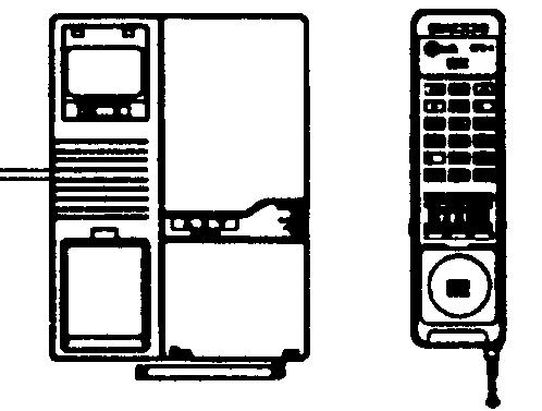
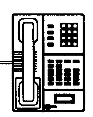
6 An Example System Setup The next page shows a control unit with two 206 modules and two 400 modules, giving the system a capacity of 12 outside lines and 12 extensions. Although your system may differ, this example will give you an idea of the types of equipment you can connect to it. In the example, system phones and industry-standard devices are connected to nine extensions. The circled numbers in the figure refer to the following list, which gives a brief description of the system s hardware components. Control Unit The control unit consists of these components: Backplane. The backplane channels power to the system and connects the system modules. 206 Modules. Each 206 module has jacks for two lines and six extensions. 400 Modules. Each 400 module provides four line jacks but no extensions. Notice that the 400 modules are installed to the right of the 206 modules. Processor Module. The processor module contains the software that provides the system s features. It also has PAGE, SMDR, and MUSIC ON HOLD jacks. PAGE Jack. A loudspeaker paging system plugs directly into this modular jack. The system is compatible with any AT&T paging system, including the AT&T PagePac6 shown here. If you use equipment that rebroadcasts music or other copyrighted materials, you may be required to obtain a license from a third party such as ASCAP or BMI. Or you can purchase a Magic On Hold system from AT&T, which does not required you to obtain such as license. SMDR Jack. A call reporting (or SMDR Station Message Detail Recording) device connects directly to this jack. AT&T s Call Accounting Terminal serial printer and box are shown here. MUSIC ON HOLD Jack. AT&T s Magic on Hold is connected to this jack to provide customized music and messages for callers on hold. Other types of audio equipment (including a CD player, cassette player, or stereo receiver) can be connected using an audio cord with an RCA phono plug (not supplied). Line Jacks. The top two jacks on each 206 module, and all four jacks on each 400 module, connect to outside telephone lines. Extension Jacks. The bottom six jacks on each 206 module connect inside wiring for telephones and other telecommunications equipment. Network Interface Jacks. These jacks provide access to telephone lines from the local telephone company. Each outside line is connected to the system by plugglng one end of the line cord into one of these jacks, and the other end into a Iine jack on a 206 or 400 module. Extensions Various devices including system phones and industrystandard devices can be connected to the modular wall jacks. The modular wall jacks connect to the extension jacks in the control unit by way of the building s inside wiring. Extension 10: These devices are connected: MLS-34D Display Phone. Typically, the receptionist on programming extension 10 has an MLS-34D display phone like the one shown here. The display shows the time, dialed numbers, the duration of calls, and programming messages. An MLS-34D, MLS-18D, or MLS-12D is required for system programming at extension 10 or 11, or both. Use an MLS-18D only if there are no MLS-34D phones in the system. Similarly, use an MLS-12D only if there are no MLS-34D or MLS-18D phones in the system. Call Assistant Intercom Autodialer. An Intercom Autodialer is connected to the phone, for dialing extensions and transferring calls to them with one touch and for seeing which extensions are busy. Standard Touch-Tone Phone. During a power failure, the MLS-34D phone on extension 10 will not work, but the receptionist can use the standard phone to place and receive calls on line 1. Extension 11: MLS-34D Display Phone. Another MLS-34D is connected to programming extension 11. This means you can program the system from this extension while the receptionist at extension 10 is free to handle calls. Extension 12: MLS-18D Phone and Answering Machine. An MLS-18D phone and an answering machine are connected to this extension. Extension 13: Standard Phone. A standard phone (such as you might have in your home) is connected directly to the extension jack. Extension 14: Doorphone. A doorphone is installed at the building entrance. When someone at the entrance presses the button on the doorphone, the designated extensions in the office ring automatically. (Any number of extensions can be designated as doorphone alert extensions.) Extension 15: Bell. A loud bell is connected directly to this extension jack. Any line programmed to ring on extension 15 activates the loud bell to alert users of an incoming call in a large area, such as a warehouse. Extension 16: MLS-12D Display Phone. This display phone can handle 10 outside lines. Extension 17: Fax Machine and Standard Phone. A fax machine and standard phone share this extension. This lets you have the use of another phone when the fax machine is idle. (You can use a system phone at another extension to monitor fax machine activity see Fax Management Feature of Using Fax Machines in Chapter 4 of the PARTNER Plus Communications System Programming and Use guide.) Extension 18: MLC-6 Cordless Phone. An AT&T MLC-6 cordless phone is connected to this extension. It works like the corded MLS-6 system phone. 2 An Example System Setup


7 CONTROL UNIT EXTENSIONS Extension 10 Extension 18 Extension 17 Extension 11 Extension 16 Extension 12 Extension 15 Extension 13 Extension 14 An Example System Setup 3

.")


.")


8 Required Parts You will have up to three types of system component packages; Figure 1 shows the contents of each package in the area marked by a dashed line. Check your packages to be sure you have the parts shown here (if not, call the appropriate support telephone number as instructed on the inside front cover). Control Unit MLS-34D Programming Overlay Cover Processor Module Backplane MLS-18D/MLS-12D Programming Overlay Quick Reference Cards AC Power Cord 206 Module 400 Module 206 Module 7-foot Telephone Line Cords 400 Module 7-foot Telephone Line Cords Figure 1. Required Parts You will need to obtain four #12 screws of the appropriate type for the wall and weight of the control unit (a control unit with four 206 modules and a processor module weighs approximately 27.5 pounds or 12.3 kilograms). In addition, if you need modular telephone cords for connecting the extension jacks on the control unit to the modular connecting blocks for extensions in the equipment room, short telephone cords for wall mounting MLS-model phones, or a 355A/355AF adapter and D8W telephone cord for connecting a call reporting device, order them before installation. Refer to Product Ordering Information in Appendix B of the PARTNER Plus Communications System Programming and Use guide for ordering instructions. NOTE: A system display phone either an MLS-34D, MLS-18D, or MLS-12D is required for system programming at extension 10 and/or 11. (Make sure that the programming phone is as large as the largest phone in the system, because an MLS-12D or MLS-18D cannot program an MLS-34D. Similarly, an MLS-12D cannot program an MLS-18D.) 4 Required Parts
9 Installation Guidelines Telephones and Devices You can connect the following telephones and devices to the system: MLS- and MLC-Model System Phones. System phones require at least two-pair wiring and are compatible with AT&T 4-pair SYSTIMAX wiring. Call Assistant Intercom Autodialers with Busy Indication (MLS-CA24). You can connect an Intercom Autodialer to the system phone at extensions 10 and 11 (maximum two per system). The Intercom Autodialer has its own power supply, which must be plugged into an AC outlet. Industry-Standard Devices. Industry-standard devices (including standard phones) require one-pair mounting cords; AT&T D2R mounting cords are recommended. Standard Phones. Connect standard touch-tone or rotary dial phones to the system for: Power Failure Operation. During a power failure, system phones will not work because they require power to operate. However, if you connect standard phones to extensions 10, 16, 22, and 28, users can place and answer outside calls on lines 1, 3, 5, and 7, respectively. You can connect a standard phone either alone or combined with a system phone. (If you combine a standard phone and a system phone on one extension, you may want to turn off the standard phone s ringer during normal use.) Hotlines. A hotline extension should be connected to a standard phone, rather than a system telephone, but can ring any type of phone. A hotline phone can also be set up to ring the paging system, so announcements can be made over the loudspeaker. Do not connect a Hotline phone to extension 10, 16, 22, or 28, to keep them available for power failure use. Auxiliary Equipment. There are a variety of ways to set up fax machines, modems, and answering machines to work with the system. See Chapter 4 in the PARTNER Plus Communications System Programming and Use guide for advice on using this equipment. To connect a telephone and a standard device on the same extension, see Combination Extensions on page 6. Doorphones. You can connect up to two doorphones to the system. Do not connect doorphones to extension 10, 11, 16, 17, 22, 23, 28, or 29. Call Reporting Devices. You can connect a call reporting device to the SMDR jack on the processor module for recording call activity. In-Range Out-of-Building Protectors. Installing phones in a different building from the control unit requires AT&T In-Range Out-of-Building (IRO protectors, to prevent damage due to lightning. (IROBS must be installed by a qualified technician.) Installation Guidelines 5
. An extension with two devices connected to it is called a combination extension.")

10 Combination Extensions You can connect a standard device (such as a standard phone or an answering machine) on an extension by itself, or so that it shares an extension with another piece of equipment (either another standard device or a system phone). An extension with two devices connected to it is called a combination extension. You cannot install two system phones on the same extension, and the combined REN (Ringer Equivalence Number) of two devices on one extension cannot exceed 2.0. (The REN for a system phone is 0.0.) If your system phone has a built-in auxiliary jack, you can connect a standard device directly to the phone, without using a bridging adapter see Using A Direct Connection below. If your system phone does not provide a built-in auxiliary jack or if you want to connect two standard devices together, you must use an AT&T 267F2 bridging adapter to combine the two devices on one extension see Using a Bridging Adapter below. Using A Direct Connection Figure 2 shows you how to connect a standard device directly to a system phone, using the phone s built-in auxiliary jack. To Wall Jack To Standard Device Figure 2. Combination Extension Using Direct Connection Using a Bridging Adapter Figure 3 shows you how to connect a system phone and a standard device or two standard devices together using the 267F2 bridging adapter. Standard Device Only AT&T 267F2 Adapter System Phone or Standard Device Wall Jack Figure 3. Combination Extension Using Bridging Adapter 6 Installation Guidelines

 of a properly grounded AC electrical outlet (not controlled by a switch) and the network interface jacks. In addition, when you mount the backplane on the wall, leave at least six inches (2.")

11 Installation Procedures Before installing the system, be sure you read the safety instructions on page ii. WARNING: There are no customer-serviceable components inside the system modules or backplane. There are hazardous voltages within that can cause severe or fatal personal injury. DO NOT OPEN THE MODULES. Installing the Control Unit and Modules Install the control unit s backplane within five feet (1.5 meters) of a properly grounded AC electrical outlet (not controlled by a switch) and the network interface jacks. In addition, when you mount the backplane on the wall, leave at least six inches (2.34 cm) of clearance at the top and sides, and two feet (0.6 meters) at the front and bottom to ensure proper ventilation A) D) A) A) Hold the backplane against the wall. Using the four screw keyholes in the backplane as a template, mark screw locations on the wall. Start four #12 screws, leaving the screw heads approximately 1/4 away from the wall. Slip the backplane onto the screws and tighten them. Slide the processor module into the center slot of the control unit pressing the locking tab on the bottom of the slot as you push in the module will make insertion easier. Push slowly but firmly until the module locks into place with two snaps, and is attached to the rear of the backplane and held in place by the locking tab. Do not force the module. If it does not insert easily, remove the module, clear any obstruction, and reinsert. Slide the first 206 module into the leftmost slot of the backplane. (The system will not work if a 206 module is not installed in this slot.) Going from left to right, install 206 modules first, then any 400 (or 200) modules. The 400 modules should always be to the right of all 206 modules, so the extensions will be numbered consecutively. Hold down the locking tab and align the dovetail guides on the sides of the module with the guides on any previously inserted modules. Backplane Dovetail Guides Backplane Locking Tab Installation Procedures 7

. Main Circuit Breaker Power Jack 5 Check all green lights on the fronts of the modules.")
12 4 A) D) To power down the control unit, pull out the main circuit breaker on the control unit. On a PARTNER Plus 220V system, move the on/off switch to the off position ( O ). Press the AC power cord firmly into the power jack on the top right side of the backplane until it locks into place. Plug the other end of the power cord into a properly grounded three-prong wall outlet not controlled by a switch. To power up the control unit, push in the main circuit breaker. On a PARTNER Plus 220V system, move the on/off switch to the on position ( l ). Main Circuit Breaker Power Jack 5 Check all green lights on the fronts of the modules. If all the lights are lit, you can go to the next section; otherwise: A) If a single light is out, power down the control unit, reseat the module, then power up the control unit. If multiple lights are out, power down the control unit, reseat the first leftmost module that has a light out, then power up the control unit. If the lights are still out, call the appropriate support telephone number as instructed on the inside front cover. Lights 8 Installation Procedures
 A) Test for dial tone at the network interface jacks before connecting outside lines to the control unit. For the test, connect a standard phone to the first network interface jack.")
13 Connecting Lines and Extensions If extensions are not wired to any modular jacks, call a qualified service technician A) A) Test for dial tone at the network interface jacks before connecting outside lines to the control unit. For the test, connect a standard phone to the first network interface jack. Lift the handset and listen for dial tone. (If there is no dial tone, contact your local telephone company before continuing.) Repeat for each network interface jack. Connect line cords to the line jacks on 206 and 400 modules, starting with the top line jack on the leftmost 206 module. Route each cord through the hook on the front of the module, and then push the cords through the space below the module and out through the back. Pull the cords from behind the backplane, leaving at least two feet of slack in the cords (for future maintenance so you can easily reconnect cords after replacing system modules). Connect the free end of each line cord to the appropriate network interface jack. Network Interface Jacks A) Test the lines plug a system phone into extension 10. Press the line buttons for each outside line and listen for dial tone. Repeat for extensions 16, 22, and 28 (if available). Installation Procedures 9
14 5 A) D) 6 A) Connect modular telephone cords to 206 module extension jacks, starting at the top extension jack on the leftmost module. Route each cord through the hook on the front of the module, and then push the cords through the space below the module and out through the back. Pull the cords from behind the backplane, leaving at least two feet of slack to allow easy replacement of system modules (for future maintenance so you can easily reconnect cords after replacing system modules). Connect the free end of each modular telephone cord to the modular connecting blocks for system extensions. Place the cover on the control unit this is especially important to keep the modules dust-free and the system working efficiently. To cover the control unit, while holding the cover at an angle, gently move the top rear edge of the cover over the top of the control unit. Match up the grooves where the top edge of the cover meets the backplane, and gently push the edge into place. Lower the bottom of the cover until it is secured in place. 10 Installation Procedures

15 Connecting Caller ID Display Units To get Caller ID information for an extension, you must first subscribe to the service (on a per-line basis) from your local telephone company, then connect the units as described here. You must connect the Caller ID display unit directly to the line that supports Caller ID at the network interface jack. Additionally, you must provide a separate wiring run for the unit to the appropriate location. To have additional wiring runs installed, call a qualified service technician. NOTE: To have Caller ID for multiple lines at a single phone, you must provide a separate box and a separate wiring run for each line. 1 Insert an AT&T 267F2 bridging adapter into the network interface jack associated with the line that has Caller ID service. 2 3 A) A) Plug one end of a line cord into a jack on the bridging adapter. D) E) Plug the free end of the line cord into the appropriate line jack in the control unit. Route the cord as you did for other line and extension cords. Plug one end of a second line cord into the other jack on the bridging adapter. Plug the free end of the cord into the appropriate modular connecting block in the equipment room. Plug the Caller ID display unit into the additional modular jack provided by the separate wiring run at the appropriate location. Place the Caller ID display unit next to the phone. Make sure the Caller ID line is assigned to the extension where the Caller ID display unit is located. Refer to Line Assignment in Chapter 5 of the PARTNER Plus Communications System Programming and Use guide for programming instructions. System Phone Network Interface Jacks Caller ID Display Unit Installation Procedures 11
16 Assembling System Phones You can either desk mount or wall mount a system phone. If the system phone is manufactured with a separate stand, you can use the stand to either wall mount the phone or raise the angle of the phone when desk mounting. (The stand is required for MLS-34D phones.) Alternatively, some system phones such as the MLS-18D are manufactured with a fixed stand. Any instructions below for installing the stand do not apply to this type of phone. (Wall mounting is not recommended for display phones.) Desk Mounting 1 A) D) 2 A) 3 A) Plug one end of the handset cord into the jack on the handset and the other end into the small jack on the left side of the base. For an MLS-34D phone, go directly to Step 2. Plug one end of the phone cord into the jack on the bottom of the phone. If the phone has multiple jacks, plug the cord into the LINE jack. Push the cord into place along the channel on the bottom of the phone. If you want to raise the angle of the phone, go to Step 2; if not or if you have a phone with a fixed stand go to Step 3. To install the telephone stand (required for the MLS-34D), gently place the phone upside down, with the low end of the phone to your right. Insert the tab on the narrow end of the stand into the right slot on the bottom of the phone. (For an MLS-34D phone, feed the cord through the hole in the center of the stand and plug it in.) Insert the other tab into the left slot, pushing the stand down and slightly inward until the tab locks into place. Turn the phone over so it is right side up. Remove the plastic cover from the phone. Label the button sheet to show any programmed lines or button features, then place it on the phone so the holes on the sheet fit over the buttons. Carefully replace the plastic cover. Slide the Quick Reference card under the telephone. 12 Installation Procedures

17 Wall Mounting If you wall mount a display phone, the display may be difficult to read, so desk mounting is recommended. (Wall mounting instructions apply to corded MLS-model phones only. To wall mount an MLC-6 cordless phone, follow the instructions in the booklet provided with the phone.) Wall Mounting Phones with Separate Stands Reverse the plastic hook that sits in the earpiece part of the handset cradle. A) A) To install the telephone stand, gently place the phone upside down with the low end of the phone to your right. Insert the tab on the narrow end of the stand into the left slot on the base of the phone. (For an MLS-34D phone, feed the cord through the hole in the center of the stand and plug it in.) Insert the other tab into the right slot, pushing the stand down and slightly inward until the tab locks into place. Insert the phone cord through the center of the stand and plug it into the jack on the base of the phone, then plug the other end into the modular wall jack. Mount the phone on the wall plate using the screw keyholes on the base of the stand. For proper mounting, the wall plate must be an AT&T 630B connecting block. Connect the handset cord as described in Desk Mounting, Step 1A, and label the button sheet as in Steps 3A and 3B. Wall Mounting Phones with Fixed Stands Make sure the telephone cord is unplugged from the bottom of the phone before proceeding. 1 A) Reverse the plastic hook that sits in the earpiece part of the handset cradle. Gently place the phone upside down. Installation Procedures 13
18 2 A) 3 A) Unscrew the phone s four mounting screws and lift the base of the phone off the top. CAUTION: Do not touch electrical circuitry. To do so will expose you to a risk of electrical shock and possibly damage the equipment. Turn the base of the phone upside down so that the phone base can be mounted parallel to the wall and then place it back on the base. Replace the four mounting screws. Insert the phone cord through the center of the stand and plug it into the jack labeled AUX on the bottom of the phone. Plug the other end into the modular wall jack. Mount the phone on the wall plate using the screw keyholes on the base of the stand. For proper mounting, the wall plate must be an AT&T 630B connecting block. Connect the handset cord as described in Desk Mounting, Step 1A, and label the button sheet as in Steps 3A and 3B. Mounting Screws Connecting and Testing Telephones 1 To connect a phone, plug the modular telephone mounting cord into a modular wall jack or directly into a 206 module extension jack. (If you are connecting a standard phone and its mounting cord is loose, try an AT&T D2R mounting cord instead.) To install two phones (or other devices) on a single extension jack, see Combination Extensions earlier in this guide 2 A) Test the telephone for proper operation to test the power and lights on a system phone, press and hold the [ # ] button for five seconds. Before releasing the [ # ] button, lift the handset. All lights should light, the ringer should sound, and (on the MLS-34D, MLS-18D, or MLS-12D phones only) a test pattern should appear on the display. (If not, call the appropriate support telephone number as instructed on the inside front cover.) Replace the handset; the phone is now in normal operating mode. 14 Installation Procedures


 Route the cord as you did for line and extension cords, and then connect it to the audio source.")

 in Chapter 5 of the PARTNER Plus Communications System Programming and Use")
19 Connecting Paging, Music-On-Hold, and Call Reporting (SMDR) Devices Only steps for connection to the processor module are provided here. Refer to Chapter 4 of the PARTNER Plus Programming and Use guide and the manufacturer s instructions for additional information on installing, programming, and using these devices. Paging System 1 Insert the modular plug into the PAGE jack on the processor module. 2 Route the cord as you did for line and extension cords, then connect it to the paging system. Music-on-Hold Audio Source If you use equipment that rebroadcasts music or other copyrighted materials, you may be required to obtain a license from a third party such as ASCAP or BMI. Or you can purchase a Magic On Hold system from AT&T, which does not require you to obtain such a license. 1 A) Insert an RCA phono plug into the MUSIC ON HOLD jack on the processor module. 2 A) Route the cord as you did for line and extension cords, and then connect it to the audio source. First set the unit s volume to the lowest setting. Use a flathead screwdriver to turn the volume control on the processor module counterclockwise until it stops. Place a call on hold and listen while adjusting the volume, clockwise. If you do not hear music at any setting, check Music On Hold (#602) in Chapter 5 of the PARTNER Plus Communications System Programming and Use guide. PAGE Jack Paging System (optional) Volume Control MUSIC ON HOLD Jack Audio Source (optional) Call Reporting (SMDR) Printer 1 Insert one end of a D8W modular cord into the SMDR jack on the processor module. 2 Plug the other end into an AT&T 355A adapter and then plug the 355A adapter into the RS-232C serial port on the printer. SMDR Jack AT&T Call Accounting Terminal Printer (optional) Installation Procedures 15

 D) A) Unplug the phone s modular telephone cord from the jack on the bottom of the phone and the wall jack, and save the cord for Step 1D.")
 Route the other end through the groove at the back of the autodialer and plug it into the OUT jack.")
20 Connecting Intercom Autodialers Since the autodialer has a fixed stand, you may need to adjust the height of the system phone by installing a stand to match the height of the autodialer. Refer to Step 2 of Desk Mounting under Assembling System Phones for instructions. You can wall mount an Intercom Autodialer to work next to a wall-mounted system phone; however, wall-mounting system display phones is not recommended. 1 2 A) D) A) Unplug the phone s modular telephone cord from the jack on the bottom of the phone and the wall jack, and save the cord for Step 1D. Plug one end of the D8W cord, supplied with the autodialer, into the jack on the bottom of the phone. (If the phone has multiple jacks, plug the cord into the LINE jack.) Route the other end through the groove at the back of the autodialer and plug it into the OUT jack. Route one end of the modular telephone cord through the groove at the back of the autodialer and plug it into the IN jack; plug the other end into the wall jack for extension 10 or 11. Connect the keyed power cord, supplied with the autodialer, to the POWER jack on the bottom of the autodialer, routing it through the groove as you did in Step 1. If the keyed power cord is not attached to the power supply unit, plug the free end of the cord into the modular jack on the power supply unit; otherwise, go to Step 2C. Plug the power unit into the electrical outlet. Wall Jack In Power Unit Out Power 3 A) CAUTION: Use only the power unit supplied by AT&T for the Intercom Autodialer. Arrange the autodialer on your desk next to the phone. Remove the plastic cover from each autodialer and label the button sheet with employee names. Place the button sheet back on the autodialer, and then carefully replace the plastic cover. 16 Installation Procedures
 3 A) 4 On a PARTNER Plus 220V system, move the on/off switch to the off position ( O ).")
21 Equipment Upgrades Adding New Modules 1 A) To power down the control unit, pull out the main circuit breaker. 2 A) 3 A) 4 On a PARTNER Plus 220V system, move the on/off switch to the off position ( O ). To remove the cover, place one hand on the handle on the bottom front of the cover and place your other hand on the top of the cover. Gently pull the cover up from the bottom and tilt it towards the top until it detaches from the backplane. Before you insert the new module, make sure that all 400 (or 200) modules are installed to the right of all 206 modules. Also, remember to hold down the locking tab and to align the dovetail guides on the sides of the modules as you insert the new module. Push the module slowly but firmly until it locks into place with two snaps, and is attached to the rear of the backplane and held in place by the locking tab on the bottom of the slot. Do not force the module. If it does not insert easily, remove the module, clear any obstruction, and reinsert. See Connecting Lines and Extensions for instructions on connecting line and/or extension jack cords to the new module. To power up the control unit, push in the main circuit breaker. On a PARTNER Plus 220V system, move the on/off switch to the on position ( l ). Check all green lights on the fronts of the modules. If all the lights are lit, installation is complete; otherwise: A) If a single light is out, power down the control unit, reseat the module, then power up the control unit. If multiple lights are out, power down the control unit, reseat the first leftmost module that has a light out, then power up the control unit. If the lights are still out, call the appropriate support telephone number as instructed on the inside front cover. Handle Main Circuit Breaker Lights Power Jack Dovetail Guides Locking Tab Equipment Upgrades 17


22 5 A) To replace the cover, while holding the cover at an angle, gently move the top rear edge of the cover over the top of the control unit and match up the grooves where the top edge of the cover meets the backplane. Gently push the edge into place. Lower the bottom of the cover until it is secured in place. Replacing System Modules 1 A) To power down the control unit, pull out the main circuit breaker. On a PARTNER Plus 220V system, move the on/off switch to the off position ( O ). To remove the cover, place one hand on the handle on the bottom front of the cover and place your other hand on the top of the cover. Gently pull the cover up from the bottom and tilt it towards the top until it detaches from the backplane. Handle Main Circuit Breaker Power Jack 2 A) Check the slack in the wires. If there is not enough slack to remove the module without pulling the line and extension cords free, label and disconnect the wires before continuing with Step 2B. Place one hand on top of the module. With your other hand, grip the plastic bracket on the bottom front of the module, and use your middle finger to hold down the locking tab just below the bracket. Pull out the old module. To insert the replacement, hold down the locking tab and align the dovetail guides on the sides of the modules. Push slowly but firmly until the module locks into place with two snaps, and is attached to the rear of the backplane and held in place by the locking tab. Do not force the module. If it does not insert easily, remove the module, clear any obstruction, and reinsert. Locking Tab 18 Equipment Upgrades
. 4 Check all green lights on the fronts of the modules.")
23 3 A) Connect the line and extension cords one at a time, making sure to place the correct cords into their corresponding jacks on the new module. To power up the control unit, push in the main circuit breaker. On a PARTNER Plus 220V system, move the on/off switch to the on position ( l ). 4 Check all green lights on the fronts of the modules. If all the lights are lit, installation is complete; otherwise: A) If a single light is out, power down the control unit, reseat the module, then power up the control unit. If multiple lights are out, power down the control unit, reseat the first leftmost module that has a light out, then power up the control unit. If the lights are still out, call the appropriate support telephone number as instructed on the inside front cover. 5 A) To replace the cover, while holding the cover at an angle, gently move the top rear edge of the cover over the top of the control unit and match up the grooves where the top edge of the cover meets the backplane. Gently push the edge into place. Lower the bottom of the cover until it is secured in place. Lights Equipment Upgrades 19
24 Specifications Capacities System 206 Module Extension Jack 12 outside lines via line jacks on 2 outside lines Maximum 2 devices per extension two 206 plus two 400 modules 6 extensions jack, total REN on jack not to exceed 2.0* (System phone REN: 0.0 (zero)) 24 extensions via extension jacks on four 206 modules 400 Module 1 loudspeaker paging system 4 outside lines No more than one system phone via PAGE jack on processor module 1 audio source via MUSIC ON For programming, a system display HOLD jack on processor module (RCA phono plug required) 1 call reporting device via SMDR jack on processor module (355A/F adapter required) 2 doorphones via 2 ext. jacks per jack phone must be connected to extension 10 or 11. Dimensions and Weights (approx.) 11"(D) x 17"(H) x 1.5"(W) or 27.9 x 43.2 x 3.8 cm Processor Module 206 module 11"(D) x 17"(H) x 1.5"(W) or 27.9 x 43.2 x 3.8 cm 400 module 11"(D) x 17"(H) x 1.5"(W) or 27.9 x 43.2 x 3.8 cm Backplane & cover 12"(D) x 19"(H) x 11"(W) or 30.5 x 48.3 x 27.9 cm MLS-34D phone 9.7"(D) x 5.3"(H) x 10"(W) or 24.6 x 13.5 x 25.4 cm MLS-18D phone 9.5"(D) x 5"(H) x 6.75"(W) or 24.1 x 12.7 x 17.1 cm MLS-12D phone 9.5"(D) x 5"(H) x 6.75"(W) or 24.1 x 12.7 x 17.1 cm MLS-12 phone 9.5"(D) x 5"(H) x 6.75"(W) or 24.1 x 12.7 x 17.1 cm MLS-6 phone 9.5"(D) x 5"(H) x 6.75"(W) or 24.1 x 12.7 x 17.1 cm 9.4"(D) x 3.4"(H) x 7"(W) or 23.9 x 8.6 x 17.8 cm MLC-6 phone MLS-CA24 Autodialer 9.7"(D) x 5.3"(H) x 3.4"(W) or 24.6 x 13.5 x 8.6 cm 4.0 lbs or 1.8 kgs 4.5 lbs or 2.0 kgs 4.0 lbs or 1.8 kgs 5.5 lbs or 2.5 kgs 3.1 lbs or 1.4 kgs 2.8 lbs or 1.3 kgs 2.8 lbs or 1.3 kgs 2.7 lbs or 1.2 kgs 2.7 lbs or 1.2 kgs 2.8 lbs or 1.3 kgs 1.3 lbs or 0.6 kgs Switch Fabric Full digital, nonblocking Electrical 10 Watts (35 BTUs/hour) per 400 module, normal and maximum power consumption Specifications 65 Watts (225 BTUs/hour) per 206 module during normal operation 100 Watts (350 BTUs/hour) per 206 module during maximum power consumption 4 Amps maximum current at full system capacity (processor module and four 206 modules) On a PARTNER Plus 220V System: 2.2 Amps maximum current 4-day memory backup (96 hours) Processor microprocessor, 64K RAM, 256K ROM Module Specifications Extension Ringing voltage: +5VDC, -140 VDC peak to peak; trapezoidal wave shaping Jack On a PARTNER Plus 220V System: +5VDC, -150 VDC peak to peak Specifications 35- to 38-Volt talk battery Ringing frequency: 20 Hz PAGE Jack Draws current on inner wire pair Specifications Provides contact closure on outer wire pair 600 Ohm impedance * The two devices combined on an extension jack can be a system phone with a standard device, or two standard devices; DO NOT connect two system phones to the same extension jack. If a device lists two RENs, use the higher number when adding up RENs. 20 Specifications
25 SMDR Output 1200 baud Format No parity 8 data bits 2 stop bits Environmental Mount on a wall at least 2 feet (0.6 meters) from the floor (wall mounting required) Requirements Locate within 5 feet (1.5 meters) of the network interface jacks and an electrical outlet not Control Unit controlled by a switch, using supplied 7-foot (2.1-meter) cords Operating temperature 32 to +104 F (0 to +40, not in direct sunlight Humidity 15% 90%, noncondensing For proper ventilation and easy replacement of modules, provide at least 6" (2.34cm) clearance at the top and sides and 2 feet (0.6 meters) at the front and bottom of the control unit. Locate in an area free of excess moisture, corrosive gases, dust, and chemicals Electrical VAC, Hz, 3-prong outlet separate ground, separately fused at 15 Amps Requirements On a PARTNER Plus 220V System: VAC, fused at 10 Amps Outlet must not be controlled by an on/off switch Grounding to comply with Underwriters Laboratories (UL) 1459: A. An insulated grounding conductor that is not smaller in size and equivalent in insulation material and thickness to the grounded and ungrounded branch circuit supply conductors, except that it is green with or without one or more yellow stripes, is to be installed as part of the circuit that supplies the product or system. B. The grounding conductor mentioned in item A is to be connected to ground at the service equipment. C. The attachment-plug receptacles in the vicinity of the product or system are all to be of a grounding type, and the grounding conductors serving these receptacles are to be connected to earth ground at the service equipment. Requirements for Out-of-Building Extensions Installation of a telephone or other standard (tip/ring) device in another building requires the following In-Range Out-of-Building (IRO protectors to protect the control unit and device from electrical surges: MLS-model telephone: two AT&T IROB protectors Standard device: one AT&T IROB protector plus one carbon block protector Wiring MLS-model phones: AT&T SYSTIMAX or at least 2-pair (4-wire) star ( home run not loop ) Other standard telecommunications equipment (single-line phones, fax machines, answering machines, etc.): 1-pair (2-wire) mounting cords (AT&T D2R mounting cords recommended) Bridging adapter: AT&T 267F2 Range: 1,000 feet (305 meters) for MLS phones; 3,000 feet (915 meters) for standard devices Safety U.S.: Meets UL 1459 Issue 2 Requirements Canada: Meets CSA C22.2, 225 Government U.S.: FCC Part 68 Approvals and FCC registration number (U.S.): AS5 USA KF-E Local Phone FCC Part 15 Class A Company REN (outside line jack): 0.9A per line jack Information Jack type: RJ11C Canada: DOC CP01, Issue 7 DOC registration number (Canada): DOC CS03, Issues 6 & 7 Load Number = 7 Loop start lines Specifications 21
26 Issue 1 June 1992 Graphics 1988
AT&T. PARTNER Plus Communications System Release 3.1 Installation
 AT&T PARTNER Plus Communications System Release 3.1 Installation Copyright 1993 AT&T AT&T 518-455-218 All Rights Reserved Issue 1 Printed in U.S.A. October 1993 Notice Every effort was made to ensure that
AT&T. PARTNER II Communications System Release 4.0 Installation
 AT&T PARTNER II Communications System Release 4.0 Installation Copyright 1994 AT&T All Rights Reserved Printed in U.S.A. AT&T 518-455-325 Issue 1 August 1994 Notice Every effort was made to ensure that
PARTNER Plus Communications System Release 2
 Lucent Technologies Bell Labs Innovations PARTNER Plus Communications System Release 2 Installation and Use AT&T Lucent Technologies - formerly the communications systems and technology units of AT&T 518-455-210
AT&T. PARTNER II Centrex Communications System Release 1 Installation and Use
 AT&T PARTNER II Centrex Communications System Release 1 Installation and Use Copyright 1991 AT&T All Rights Reserved Printed in U.S.A. AT&T 518-455-330 Issue 1 November 1991 Notice Every effort was made
AT&T. PARTNER Plus Communications System Release 3. Programming and Use
 AT&T PARTNER Plus Communications System Release 3 Programming and Use Copyright 1992 AT&T All Rights Reserved Printed in U.S.A. AT&T 518-455-212 Issue 1 June 1992 Notice Every effort was made to ensure
User Guide CPSMP VAC Power Supply Module: PointSystem CPSMC Accessory CPSMC Accessory. Contents.
 User Guide CPSMP-205 110 240 VAC Power Supply Module: PointSystem CPSMC1800-200 Accessory CPSMC1900-100 Accessory Contents Contents...1 Description...1 Cautions and Warnings...2 Definitions...2 Power supply
Allworx Tx 92/24 Telephone Expander Installation Guide
 Allworx Tx 92/24 Telephone Expander Installation Guide No part of this publication may be reproduced, stored in a retrieval system, or transmitted, in any form or by any means, electronic, mechanical,
Multiple Digital Messaging Unit
 HARRIS DRACON DIVISION Multiple Digital Messaging Unit Installation and Configuration Copyright 994 Harris Dracon All Rights Reserved Written/Printed in U.S.A. 0II7404-00 Issue, Nov. 994 Notice Every effort
PARTNER Contact Closure Adjunct
 Closure Installation Instructions BEFORE STARTING INSTALLATION, READ AND UNDERSTAND ALL SAFETY INSTRUCTIONS ON PAGE. The is used with a Advanced Communications System processor module (available separately)
This document will show you how to set up the Hotwire 6205 ADSL Modem, and how to customize its configuration to get the most out of this product.
 Hotwire 6205 ADSL Modem Installation Instructions Document Number 6205-A2-GZ40-10 September 2004 Introduction Congratulations on becoming the owner of a Hotwire ADSL USB Modem. You will now be able to
888385_01 Install.book Page 1 Wednesday, November 11, :45 PM. SMDR6 Installation Guide
 888385_01 Install.book Page 1 Wednesday, November 11, 1998 2:45 PM SMDR6 Installation Guide 888385_01 Install.book Page 2 Wednesday, November 11, 1998 2:45 PM 888385_01 Install.book Page i Wednesday, November
CIB 3125 (122A) Off-Premises Range Extender. Installation Instructions. Installed By Qualified Technician Only CIB
 Off-Premises Range Extender. Installation Instructions. Installed By Qualified Technician Only CIB") CIB 3125 (122A) Off-Premises Range Extender Installation Instructions Installed By Qualified Technician Only CIB 3125 106793441 1992 AT&T All Rights Reserved Printed in USA Issue 3 August 1992 NOTICE Every
CIB 3125 (122A) Off-Premises Range Extender Installation Instructions Installed By Qualified Technician Only CIB 3125 106793441 1992 AT&T All Rights Reserved Printed in USA Issue 3 August 1992 NOTICE Every
THIS SYMBOL IS INTENDED TO ALERT THE USER OF THE PRESENCE OF IMPORTANT OPERATING AND MAINTENANCE (SERVICING) INSTRUCTIONS IN THE OWNER'S MANUAL.
 INSTRUCTIONS IN THE OWNER'S MANUAL.") IMPORTANT SERVICE INFORMATION Read this manual before attempting to setup or use this instrument. It contains important information regarding safe installation and use. Keep this manual for future reference.
IMPORTANT SERVICE INFORMATION Read this manual before attempting to setup or use this instrument. It contains important information regarding safe installation and use. Keep this manual for future reference.
AT&T. ZoneMate 3 Service Manual. PagePac 20 Voice Paging System. MERLIN CS Connection And Operation
 AT&T PagePac 20 Voice Paging System ZoneMate 3 Service Manual MERLIN CS Connection And Operation ZoneMate 3 Service Manual For PagePac 20 Voice Paging System and Merlin* Communications System Models 1030
Installation Guide. Wyse Rx0L Thin Client Flash and RAM Upgrade Option Kit. Issue: PN: L Rev. A
 Installation Guide Wyse Rx0L Thin Client Flash and RAM Upgrade Option Kit Issue: 052209 PN: 883884-11L Rev. A ii Copyright Notice 2009, Wyse Technology Inc. All rights reserved. This manual and the software
INSTRUCTION MANUAL DISTRIBUTION UNIT. Please read this manual thoroughly before use, and keep it handy for future reference.
 INSTRUCTION MANUAL DISTRIBUTION UNIT Please read this manual thoroughly before use, and keep it handy for future reference. ISSUE 1 May 2006 LIMITATION OF LIABILITY THE INFORMATION IN THIS PUBLICATION
DRD-4 DRD-4 JULY 1992 FX140A CUSTOMER SUPPORT INFORMATION
 JULY 1992 FX140A CUSTOMER SUPPORT INFORMATION Order toll-free in the U.S. 24 hours, 7 A.M. Monday to midnight Friday: 877-877-BBOX FREE technical support, 24 hours a day, 7 days a week: Call 724-746-5500
AT&T. MERLIN Plus COMMUNICATIONS SYSTEM. Release 2 Installation Manual
 AT&T MERLIN Plus COMMUNICATIONS SYSTEM Release 2 Installation Manual 1988 AT&T Issue 1 All Rights Reserved August, 1988 Printed in USA NOTICE The information in this document is subject to change without
345 Encinal Street Santa Cruz, CA
 Printed in the U.S.A. 69047-01 (11 04) 2000 2004 Plantronics, Inc. All rights reserved. Plantronics, the logo design, Plantronics and the logo design combined are trademarks or registered trademarks of
SPECIAL APPLICATION MANUAL PART NUMBER: TNP121UL. Tilt N Plug Jr. Table Top Interconnect Box USER'S GUIDE
 MANUAL PART NUMBER: 400-0429-001 TNP121UL Tilt N Plug Jr. Table Top Interconnect Box USER'S GUIDE INTRODUCTION Your purchase of the UL Listed TNP121UL, Tilt N Plug Jr. Interconnect Box is greatly appreciated.
User s Guide CPSMC0200-2x0 Dual-Slot PointSystem Chassis
 User s Guide CPSMC0200-2x0 Dual-Slot PointSystem Chassis The Transition Networks CPSMC0200-2x0 series dual-slot PointSystem chassis is designed for installation of one or two selectable Transition Networks
Big button Speakerphone MODEL: FC-8814
 FUTURE CALL Big button Speakerphone MODEL: FC-8814 USER MANUAL Please follow instructions for repairing if any otherwise do not alter or repair any parts of device except specified. IMPORTANT SAFETY INSTRUCTIONS
FUTURE CALL USER MANUAL PICTURE PHONE WITH SPEAKERPHONE MODEL: FC-1007 SP / PD
 FUTURE CALL PICTURE PHONE WITH SPEAKERPHONE MODEL: FC-1007 SP / PD USER MANUAL Please follow instructions for repairing if any otherwise do not alter or repair any parts of device except specified. IMPORTANT
Four IFB. Multi Line Phone Bridge. User Guide. JK Audio. Warranty
 Warranty Four IFB is covered by a 2-year warranty to be free from defective workmanship and materials. In the event that the Four IFB needs repair, you must call us to get an authorization, and then carefully
MODEL: VSP735. Compliance. About this Guide. Parts Checklist. FCC part 15. Industry Canada
 QUICK REFERENCE GUIDE Compliance About this Guide FCC part 15 This quick start guide provides a reference for the external features of the phone and basic installation instructions. This device complies
BIG BUTTON PHONE WITH ONE TOUCH DIALING AND
 FUTURE CALL LLC BIG BUTTON PHONE WITH ONE TOUCH DIALING AND 40db HANDSET VOLUME MODEL: FC-1507 USER MANUAL Please follow instructions for repairing if any otherwise do not alter or repair any parts of
CANADIAN D.O.C. WARNING
 Each product and program carries a respective written warranty, the only warranty on which the customer can rely. Avery Dennison Corp. reserves the right to make changes in the product, the programs, and
PARTNER Advanced Communications System. Installation, Programming, and Use
 PARTNER Advanced Communications System Installation, Programming, and Use 518-456-803 Issue 7 April 2009 Copyright 2009 Document Number: 518-456-803 Avaya Inc. Issue: 7 All Rights Reserved Date: April
ISDN 8510T Voice Terminal Instructions for Changing the EPROM
 - ISDN 8510T Voice Terminal Instructions for Changing the EPROM COMCODE 106910698 555-021-753 Issue 1, October 1992 1 IMPORTANT SAFETY INSTRUCTIONS When using your telephone equipment and installing this
Installation Job Aid for Ethernet Routing Switch 3600 Series
 Installation Job Aid for Ethernet Routing Switch 3600 Series Notices NN47213-303 Issue 03.01 November 2017 Notice paragraphs alert you about issues that require your attention. Following are descriptions
BS 287 DUAL CHANNEL POWER SUPPLY. User Manual. January 2017 V1.0
 BS 287 DUAL CHANNEL POWER SUPPLY User Manual January 2017 V1.0 Table of contents 1.0 SAFETY INSTRUCTIONS... 3 2.0 GENERAL DESCRIPTION PS 289... 4 3.0 MECHANICAL INSTALLATION... 5 4.0 MAINS POWER & SAFETY
SuperBus 2000 Phone Interface/Voice Module Installation Instructions
 SuperBus 2000 Module Installation Instructions Product summary The SuperBus 2000 (PIV) Module provides phone and voice functions for the Concord, Concord 4, and Concord Express (v4) panels. The PIV module
AT&T. PARTNER Communications System Remote Administration Unit. Installation and Use
 AT&T PARTNER Communications System Remote Administration Unit Installation and Use Copyright 1994 AT&T All Rights Reserved Printed U.S.A. AT&T 518-455-050 Issue 1 April 1994 Notice Every effort was made
PAGEPAC 6 V INSTALLATION There are several ways to connect PagePac 6 to your telephone system.
 PagePac by Issue 2 PAGEPAC 6 V-5323006 INTRODUCTION PagePac 6 is a compact, 6 watt, voice-paging system that integrates single-zone paging capability to your telephone system. Dimensions/Weight 6.0 W x
Infosystem Remote Touchscreen Installation Instructions
 Infosystem Remote Touchscreen Installation Instructions DOC. #569102100 A 7/30/04 PRINTED IN U.S.A. Regulatory Compliance Safety This device has been tested and found to be in compliance with the requirements
AREA CODE CHANGE. Please note that the area code for Paradyne Corporation in Largo, Florida has changed from 813 to 727.
 AREA CODE CHANGE Please note that the area code for Paradyne Corporation in Largo, Florida has changed from 813 to 727. For any Paradyne telephone number that appears in this manual with an 813 area code,
INFORMATION AMPLIFIER TA-102 OPERATING INSTRUCTIONS TABLE OF CONTENTS
 OPERATING INSTRUCTIONS INFORMATION AMPLIFIER TA-102 INFORMATION AMPLIFIER TA-102 MIC AUX POWER TABLE OF CONTENTS 1. SAFETY PRECAUTIONS... 2 2. GENERAL DESCRIPTION... 4 3. EACH PART NAME AND FUNCTIONS Top
OWNER S INSTRUCTION MANUAL
 OWNER S INSTRUCTION MANUAL THANK YOU FOR PURCHASING THIS TELEPHONE Your new telephone was made by people who take a great deal of PRIDE in producing quality products to assure you years of trouble-free
SuperLine IAD Models 6501, 6502, 6510, 6511, and 6512 Installation Instructions
 6512 PWR ALM TST LINE ETHERNET SuperLine IAD Models 6501, 6502, 6510, 6511, and 6512 Installation Instructions Document Number 6500-A2-GN10-00 September 1999 SuperLine TM IAD Front View Rear View BASE
Installation and User Instructions
 7KH$$QDORJ,QWHUIDFH0RGXOH (for connection with the 646D+M and 644D+M Telephones) Installation and User Instructions [This module meets U.S. Analog Telephone Interface Requirements.] Document Ordering No.
Integrated Services Digital Network (ISDN) ISDN 8503T Voice Terminal Feature Package 3. User s Manual
 ISDN 8503T Voice Terminal Feature Package 3. User s Manual") Integrated Services Digital Network (ISDN) ISDN 8503T Voice Terminal Feature Package 3 User s Manual COMCODE 106454507 555-021-728 Issue 1, October 1991 1 WARRANTY All terms and conditions specified in
Integrated Services Digital Network (ISDN) ISDN 8503T Voice Terminal Feature Package 3 User s Manual COMCODE 106454507 555-021-728 Issue 1, October 1991 1 WARRANTY All terms and conditions specified in
Obtaining Documentation and Submitting a Service Request, page xvii Safety Warnings, page xvii Safety Guidelines, page xx
 Preface Obtaining Documentation and Submitting a Service Request, page xvii Safety s, page xvii Safety Guidelines, page xx Obtaining Documentation and Submitting a Service Request For information on obtaining
Operator s Handbook. Monarch FreshMarx 9417 Food Freshness System. TC9417OH Rev. AE 1/ Avery Dennison Corp. All rights reserved.
 Operator s Handbook Monarch FreshMarx 9417 Food Freshness System TC9417OH Rev. AE 1/2015 2013 Avery Dennison Corp. All rights reserved. Each product and program carries a respective written warranty, the
PICTURE PHONE WITH ONE TOUCH DIALING MODEL: FC-0613
 FUTURE CALL PICTURE PHONE WITH ONE TOUCH DIALING MODEL: FC-0613 USER MANUAL Please follow instructions for repairing if any otherwise do not alter or repair any parts of device except specified. IMPORTANT
Monarch 9414 Printer. TC9414EM 7/99 Rev. AB 1999 Monarch Marking Systems, Inc. All rights reserved.
 Monarch 9414 Printer TC9414EM 7/99 Rev. AB 1999 Monarch Marking Systems, Inc. All rights reserved. Each product and program carries a respective written warranty, the only warranty on which the customer
TELink FLASH. Model 700a. Installation and Operation Instructions. Magic On Hold is a Registered Service Mark and Trademark of Avaya Communications
 TELink FLASH Model 700a Installation and Operation Instructions Magic On Hold is a Registered Service Mark and Trademark of Avaya Communications Issue 1, 8/01 Printed in USA FCC Notice WARNING: This equipment
QS7800A Network Interface ControlBus Module for 7800 SERIES Relay Modules
 QS7800A Network Interface ControlBus Module for 7800 SERIES Relay Modules APPLICATION PRODUCT DATA The QS7800A Network Interface ControlBus Module allows remote monitoring and diagnostics of the 7800 SERIES
INSTALLATION INSTRUCTIONS
 INSTALLATION INSTRUCTIONS READ THIS MANUAL CAREFULLY! FAILURE TO INSTALL THIS EQUIPMENT PER THESE INSTRUCTIONS WILL VOID THE WARRANTY. AM16904-1 Rev. C pg. 1 of 12 SPECIAL NOTICES The following notices
BS 181 SINGLE CHANNEL POWER SUPPLY USER MANUAL
 BS 181 SINGLE CHANNEL POWER SUPPLY USER MANUAL August 2016 This product is designed and manufactured by: ASL Intercom B.V. Zonnebaan 42 3542 EG Utrecht The Netherlands Phone: +31 (0)30 2411901 Fax: +31
Network Camera. Quick Guide DC-B1203X. Powered by
 Network Camera Quick Guide DC-B1203X Powered by Safety Precautions English WARNING RISK OF ELECTRIC SHOCK DO NOT OPEN WARNING: TO REDUCE THE RISK OF ELECTRIC SHOCK, DO NOT REMOVE COVER (OR BACK). NO USER-SERVICEABLE
Connectivity Peripherals User s Guide. Point 510 Point 1600
 Connectivity Peripherals User s Guide Point 510 Point 1600 Connectivity Peripherals User s Guide Point 510 Point 1600 Fujitsu Personal Systems, Inc. has made every effort to ensure the accuracy and completeness
6220 and 6225 Telephones Quick Reference
 6220 and 6225 Telephones Quick Reference Document Ordering No. 555-230-713 Comcode 108179540 Issue 1, June 1998 IMPORTANT INFORMATION SAFETY INSTRUCTIONS The most careful attention has been devoted to
AT&T. PARTNER Plus COMMUNICATIONS SYSTEM. PARTNER Plus Attendant Installation and Use
 AT&T PARTNER Plus COMMUNICATIONS SYSTEM PARTNER Plus Attendant Installation and Use Copyright 1991 AT&T All Rights Reserved Printed in U.S.A. AT&T 518-455-710 Issue 1 April 1991 Notice Every effort was
SERVICE MANUAL MODEL SSW-321-X
 SSW-321-X-ISSUE 4.0 SERVICE MANUAL FOR MODEL SSW-321-X STAINLESS STEEL WALL TELEPHONE Serving the Telephone Industry Since 1930 Communication Equipment 519 W South Park Street & Engineering Company Okeechobee,
Now with Picture Memory
 Intrasonic Technology, Inc. Color Video Door Phone / Intercom Installer s Manual Model No.V304KIT-R Now with Picture Memory Please read this manual carefully before the products are installed.technical
Quick start guide (Canada version) TL7612 DECT 6.0 cordless headset and handset lifter
 TL7612 DECT 6.0 cordless headset and handset lifter") Quick start guide (Canada version) TL7612 DECT 6.0 cordless headset and handset lifter Installation You must install and charge the battery before using the headset. STOP! See pages 10-11 for instructions.
Quick start guide (Canada version) TL7612 DECT 6.0 cordless headset and handset lifter Installation You must install and charge the battery before using the headset. STOP! See pages 10-11 for instructions.
BEETLE /Fusion Compact. Installation Guide
 BEETLE /Fusion Compact Installation Guide The reproduction, transmission or use of this document or its contents is not permitted without express authority. Offenders will be liable for damages. All rights,
NT1B-300 Rack Installation Instructions
 The NT1B-300 Rack houses 24 Tone Commander NT1B-300TC ISDN Network Terminations in a 19 rack, 23 rack, or wall mount configuration. The rack is also compatible with Lucent NT1B-300 NT1s. The rack supplies
LVN5200A-R2, rev. 1, Hardware Installation Guide
 LVN5200A-R2 LVN5250A-R2 LVN5200A-R2, rev. 1, Hardware Installation Guide Customer Support Information Order toll-free in the U.S.: Call 877-877-BBOX (outside U.S. call 724-746-5500) FREE technical support
YST-SW20 SUBWOOFER SYSTEM OWNER S MANUAL. Active Servo Technology
 CAUTION SUBWOOFER SYSTEM Active Servo RISK OF ELECTRIC SHOCK DO NOT OPEN CAUTION: TO REDUCE THE RISK OF ELECTRIC SHOCK DO NOT REMOVE COVER (OR BACK). NO USER-SERVICEABLE PARTS SIDE. REFER SERVICG TO QUALIFIED
NSD/M1 Installation Instructions
 NSD/M1 Installation Instructions DOC. #560502200 C 7/30/04 PRINTED IN U.S.A. Regulatory Compliance Safety This device has been tested and found to be in compliance with the requirements set forth in UL
Thank you for selecting UTC RETAIL s innovative Model 1170 Point of Sale solution!
 1170 POS SYSTEM 1170 INSTALLATION GUIDE Thank you for selecting UTC RETAIL s innovative Model 1170 Point of Sale solution! This Installation Guide will help you efficiently install the 1170 POS. The document
Advanced Communications System. Installation, Programming, and Use
 PARTNER Advanced Communications System Installation, Programming, and Use 518-456-803 Issue 3 March 2002 Copyright 2002 Document Number: 518-456-803 Avaya Inc. Issue: 3 All Rights Reserved Date: March
Unity 100-watt Bridgeable Power Amp
 Unity 100-watt Bridgeable Power Amp P/N 18513 User's Manual CONTENTS SAFETY WARNINGS AND GUIDELINES... 3 INTRODUCTION... 4 FEATURES... 4 CUSTOMER SERVICE... 5 PACKAGE CONTENTS... 5 PRODUCT OVERVIEW...
OWC Mercury Helios 2 ASSEMBLY MANUAL & USER GUIDE
 OWC Mercury Helios 2 ASSEMBLY MANUAL & USER GUIDE TABLE OF CONTENTS 1. INTRODUCTION...1 1.1 MINIMUM SYSTEM REQUIREMENTS 1.1.1 Apple Mac Requirements 1.1.2 PC Requirements 1.1.3 Supported PCIe Cards 1.2
1.0 Description. 2.0 Unpacking. 3.0 Installation
 ES-H, ES-HA Series Precision Balance Thank you for purchasing the Model ES-H and ES-HA precision balance. Please read all operating instructions carefully before using and note the following items to ensure
Kogan Bluetooth Karaoke System with Dual Microphones KAKAR2MICA
 Kogan Bluetooth Karaoke System with Dual Microphones KAKAR2MICA K TABLE OF CONTENTS SAFETY & WARNINGS...1 IMPORTANT SAFETY INSTRUCTIONS...1 AC CONNECTION...2 LOCATION OF CONTROLS...3 ASSEMBLY AND CONNECTIONS...4
Teligent 314 Series, Model
 Teligent 314 Series, Model 314-06 Speaker Phone Manual Installation and Basic Operations For use with the Bluetooth Converter. BTC Speaker Phone Manual, Rev. 1.00, CIS00202 TABLE OF CONTENTS FEATURE OVERVIEW...
NCH-1000 (Multiple Breaker Types) Installation Instructions
 Installation Instructions") 20M1 12345678 NCH-1000 (Multiple Breaker Types) Installation Instructions DOC. #560502100 C 7/30/04 PRINTED IN U.S.A. Regulatory Compliance Safety This device has been tested and found to be in compliance
20M1 12345678 NCH-1000 (Multiple Breaker Types) Installation Instructions DOC. #560502100 C 7/30/04 PRINTED IN U.S.A. Regulatory Compliance Safety This device has been tested and found to be in compliance
5 B&W Rear View System Camera
 5 B&W Rear View System Camera Instruction Manual MODEL: CA453 www.lorexcctv.com Copyright 2007 LOREX Technology Inc. Thank you for purchasing the Lorex 5 Black & White Rear View System Camera. This system
Model Bulk Sampling Scale. User s Manual
 Model 7050 Bulk Sampling Scale User s Manual UNITED STATES This equipment has been tested and found to comply with the limits for a Class A digital device, pursuant to Part 15 of the FCC Rules. These limits
Mercury Helios ASSEMBLY MANUAL & USER GUIDE
 Mercury Helios ASSEMBLY MANUAL & USER GUIDE TABLE OF CONTENTS INTRODUCTION...1 1.1 MINIMUM SYSTEM REQUIREMENTS 1.1.1 Apple Mac Requirements 1.1.2 PC Requirements 1.1.3 Supported PCIe Cards NOTE: Boot Camp
FUTURE CALL. Future Call Model FC-1204 Totally Hands Free Voice Activated Dialing and Answering Telephone OWNER S MANUAL AND OPERATING INSTRUCTIONS
 FUTURE CALL Future Call Model FC-1204 Totally Hands Free Voice Activated Dialing and Answering Telephone OWNER S MANUAL AND OPERATING INSTRUCTIONS Welcome to your new Totally Hands Free Voice Activated
Installation Job Aid for VSP 4850GTS
 Installation Job Aid for VSP 4850GTS Notices Release 6.1.0.0 NN46251-308 Issue 02.01 November 2017 Notice paragraphs alert you about issues that require your attention. The following paragraphs describe
PNP415/417 POP 'N PLUG WITH CUSTOM TABLETOP SURFACE USER'S GUIDE
 PNP415 PNP417 with tabletop cutout installed. MANUAL PART NUMBER: 400-0427-002 PNP415/417 POP 'N PLUG WITH CUSTOM TABLETOP SURFACE USER'S GUIDE TABLE OF CONTENTS Page PRECAUTIONS / SAFETY WARNINGS... 2
Owner s Instruction Manual
 Owner s Instruction Manual Advanced Healthcare Telephone Model 5150 Contents IMPORTANT SAFETY INSTRUCTIONS...3 BOX CONTENTS...4 FEATURES...4 ON/OFF SWITCH...4 DIAL BUTTONS...4 RECEIVER VOLUME CONTROL...4
Replacing the Power Supply
 APPENDIX B This appendix includes information on how to replace the power supply for the Cisco AS550XM universal gateway and contains the following sections: Safety Recommendations, page B-1 Required Tools
PS 289 DUAL CHANNEL POWER SUPPLY USER MANUAL
 PS 289 DUAL CHANNEL POWER SUPPLY USER MANUAL August 2016 This product is designed and manufactured by: ASL Intercom B.V. Zonnebaan 42 3542 EG Utrecht The Netherlands Phone: +31 (0)30 2411901 Fax: + 31
Fujitsu Stylistic ST4000 Series TABLET DOCK USER S GUIDE
 Fujitsu Stylistic ST4000 Series TABLET DOCK USER S GUIDE DECLARATION OF CONFORMITY according to FCC Part 15 Responsible Party Name: Fujitsu PC Corporation Address: 5200 Patrick Henry Drive Santa Clara,
RS-232/RS-422 Optical Isolator
 MAY 1998 IC457A-F IC457A-M RS-232/RS-422 Optical Isolator CUSTOMER SUPPORT INFORMATION Order toll-free in the U.S. 24 hours, 7 A.M. Monday to midnight Friday: 877-877-BBOX FREE technical support, 24 hours
SUBWOOFER SYSTEM YST-MSW10
 ACTIVE SERVO PROCESSING SUBWOOFER SYSTEM YST-MSW10 Active Servo SUBWOOFER SYSTEM YST-MSW10 Active Servo HIGH CUT HIGH LOW OWNER S MANUAL MANUAL DE INSTRUCCIONES CAUTION RISK OF ELECTRIC SHOCK DO NPT OPEN
DUAL MONO POWER AMPLIFIER INSTRUCTIONS FOR USE
 A3.2 CR DUAL MONO POWER AMPLIFIER C R MUSICAL FIDELITY A3.2 DUAL MONO POWER AMPLIFIER POWER INSTRUCTIONS FOR USE Thank you for purchasing the Musical Fidelity A3.2 CR Power Amplifier. Used properly and
Daily use. indicating that the loud speakers
 BeoLab 8002 Guide WARNING: To reduce the risk of fire or electric shock, do not expose this appliance to rain or moisture. Do not expose this equipment to dripping or splashing and ensure that no objects
6219 and 6221 Telephones Quick Reference
 6219 and 6221 Telephones Quick Reference Document Ordering No. 555-230-713 Comcode 700195746 Issue 4, July 2001 IMPORTANT INFORMATION SAFETY INSTRUCTIONS The most careful attention has been devoted to
Plug-in wireless speaker
 JBL Soundfly BT Plug-in wireless speaker Quick Setup Guide Welcome Thank you for purchasing the JBL Soundfly BT plug-in wireless speaker. Soundfly BT will fill your room with sound from your portable Bluetooth-enabled
TWISTED PAIR DISTRIBUTOR KE 0108CH-DW. Instruction Manual. Thank you for your purchase of this product
 TWISTED PAIR DISTRIBUTOR KE 0108CH-DW Instruction Manual Thank you for your purchase of this product Please be sure to read this manual completely prior to usage of this product. NOTE: This equipment has
Installation Job Aid for VSP 4450GTX-HT- PWR+
 Installation Job Aid for VSP 4450GTX-HT- PWR+ Notices Release 6.1.0.0 NN46251-305 Issue 02.01 November 2017 Notice paragraphs alert you about issues that require your attention. The following paragraphs
PR3400 Series 1.4Mp USB Cameras Hardware Guide
 PR3400 Series 1.4Mp USB Cameras Hardware Guide Manufactured by: SPOT Imaging Solutions, a division of Diagnostic Instruments, Inc. 6540 Burroughs Ave. Sterling Heights, MI 48314-2133 USA Toll-Free: 866-604-SPOT
DIAMOND ELITE SERIES USERS GUIDE
 DIAMOND ELITE SERIES USERS GUIDE COVERS MODELS L2-E L2S-E L2-5E L2S-5E L2-10E L2S-10E DIAMOND ELITE SERIES TELEPHONE DIAGRAM Hold Key Line 1 Line 2 Conference Key Handset Holder Ringer Volume Control Data
SERVICE MANUAL MODEL SSC-301-F (FORMERLY 301-FS) MODEL BLC-301-F (FORMERLY 301-F)
 MODEL BLC-301-F (FORMERLY 301-F)") SSC-301-F OR BLC-301-F-ISSUE4.0 SERVICE MANUAL FOR MODEL SSC-301-F (FORMERLY 301-FS) OR MODEL BLC-301-F (FORMERLY 301-F) CHARGE-A-CALL TELEPHONE Serving the Telephone Industry Since 1930 Communication
SSC-301-F OR BLC-301-F-ISSUE4.0 SERVICE MANUAL FOR MODEL SSC-301-F (FORMERLY 301-FS) OR MODEL BLC-301-F (FORMERLY 301-F) CHARGE-A-CALL TELEPHONE Serving the Telephone Industry Since 1930 Communication
SERVICE MANUAL FOR. MODEL MHW-341-Fr1 MAGNETIC HOOKSWITCH WALL TELEPHONE
 MHW-341-Fr1-XFD-ISSUE5.0 SERVICE MANUAL FOR MODEL MHW-341-Fr1 MAGNETIC HOOKSWITCH WALL TELEPHONE EQUIPPED WITH VOLUME CONTROL, BACKGROUND NOISE ELIMINATION, XFD PRINTED CIRCUIT, AND RECEIVER- OPERATED
ErisTerminal SIP Deskset VSP735 Quick Start Guide
 ErisTerminal SIP Deskset VSP735 Quick Start Guide Important Safety Information This symbol is to alert you to important operating or servicing instructions that may appear on the product or in this user
Start Here. Features. Model DS108 Dual Speed Hub Installation Giude
 Start Here The NETGEAR Model DS108 Dual Speed Hub is a network hub that enables users to mix and match 10 and 100 megabits per second (Mbps) devices on the same network. This capability eliminates the
User Manual AM Watt Karaoke Mixing Amplifier
 AM-148 160-Watt Karaoke Mixing Amplifier User Manual NOTE: To ensure this system works safely and to its fullest potential, please read this User s Manual carefully before operation and keep for future
On-Line CardioTheater Instruction Manual for Amplifier Models 800 and 1600 (wired)
") On-Line CardioTheater Instruction Manual for Amplifier Models 800 and 1600 (wired) Full installation instructions accompany your Cardio Theater equipment order. This On-Line version of our Installation/Instruction
On-Line CardioTheater Instruction Manual for Amplifier Models 800 and 1600 (wired) Full installation instructions accompany your Cardio Theater equipment order. This On-Line version of our Installation/Instruction
Installation of the POTS splitter card requires the following steps: Determining the cables you need. Installing the POTS splitter chassis
 5910 High Density Lifeline POTS Splitter Installation Instructions Document Number 5910-A2-GZ40-00 May 2005 About the 5910 POTS Splitter The 5910 is a double-density POTS splitter that separates the (Digital
3M RFID Tracking Pad Model 770
 3M RFID Tracking Pad Model 770 Owners Manual 3M Information and Materials Security 3M Center, Building 225-4N-14 St. Paul, Minnesota 55144-1000 xx-xxxx-xxxx-x Rev 1 Copyright 2003 3M IPC. All rights reserved.
ADL-100 Operator s Manual
 040604-510896-(01) ADL-100 Operator s Manual For Use With the Accent Disc Laminator 2004 All rights reserved. Notices: The information in this document is subject to change without notice. NO WARRANTY
CANADIAN D.O.C. WARNING
 Each product and program carries a respective written warranty, the only warranty on which the customer can rely. Avery Dennison Corp. reserves the right to make changes in the product, the programs, and
PLEASE COMPLETE YOUR OWNER REGISTRATION NOW AND MAIL TO. providing warranty service and technical support for the product.
 Owner Registration PLEASE COMPLETE YOUR OWNER REGISTRATION NOW AND MAIL TO PLANTRONICS. This is not a condition for warranty service, but will assist us in providing warranty service and technical support