STANDALONE WALL INTERFACE USB-DMX SLIM V.1.5.0
|
|
|
- Harold Garrison
- 5 years ago
- Views:
Transcription

1 STANDALONE WALL INTERFACE USB-DMX SLIM V.1.5.0
2 SUMMARY Hardware Technical Specifications... 2 General pinout and device's connector... 3 Bottom face of the interface external Contacts wiring and connections... 4 Top face of the interface... 5 Selecting mode button /- Buttons operation:... 5 LED 7-segments display operation:... 5 LED 7-segments SLEEP OPTION:... 6 External triggers operation:... 6 Infra Red triggers operation:... 6 Interfaces Master/Slave connection... 7 Setting of the Master/Slave interfaces... 8 Dmx merging in standalone... 9 Triggers configuration with the software Switch to Standalone mode LED Buttons trigger Infra Red remote triggers External contact triggers DMX IN and triggers via another DMX signal Time triggers with clock and calendar Save and recover the last scene after the power cut off: Scene trigger priorities: Wall mounting instructions For Europe and Asia Standard: 60mm center to center distance For America standard: 84mm center to center distance Back side of the SLIM housing The Secure fixing slot
3 HARDWARE TECHNICAL SPECIFICATIONS Input/output Connectors: Screw terminal (4 pins + 5 pins) Number of DMX Input/Output: 512 or 1024 (PC + Standalone) PC DMX IN triggers: Yes Standalone DMX IN triggers: 512 channels available only with a 1024 interfaces DMX Merging: Yes, 512 channels from DMX B to DMX A, only with 1024 interfaces Standalone DMX merging: 512 channel from DMX B to DMX A only with 1024 interfaces External triggers: x4 contacts (5V.) multiplexed to 15 contacts max, (20m max cable length) Infra-Red connection: Yes via an external IR module and 3 connection wires (max 15m away) Master/Slave connection: Yes, 3 wires for 16 connected interfaces max, (20 m cable distance max) DMX Speed: 1 to 45 Hz, MaB, Bk USB Mode: Yes Stand Alone Mode: Yes Internal Clock (RTC): Yes Internal calendar: Yes Backups of the internal clock: Yes, 3 weeks without power Internal memory: Yes (4 MB) Memory Capacity: 4000 steps with 512 channels, steps with 16 channels Display of signal states: DMX LED + USB LED Data display: 7 segment LED display (blue) Power supply input: 9-36V external or 5V with USB Contact Input Voltage (stand-alone): 5 V Input Current: 80 to 200 ma Power: 2 W CPU's technology: 32 bits Dimensions: H : 127 mm, W : 110 mm, D : 19 mm Weight: 250 g Color: Black / White Operating temperatures: -25 to +70 C Certificates: CE, RoHS IP Rating: IP20 Place of Use: Indoor Storage: Keep in a dry place Warranty: 24 months Compatibility: 8 and 16 bit DMX fixtures System Compatibility: Windows XP, Vista, 7, 8, 8.1, 10, MAC OS X (10.6 and higher), Linux 2


4 GENERAL PINOUT AND DEVICE'S CONNECTOR BOTTOM FACE OF THE INTERFACE External connectors: 1: GND 2: 5V. DC External trigger voltage 3: External trigger A 4: External trigger B 5: External trigger C 6: External trigger D 7:Master/Slave Clock 8: Master/Slave Data 9: External input power 9-36 V (mandatory) 10: GND 11: Infra Red signal 12: DMX2 - data 13: DMX2 + data 14: DMX1 - data 15: DMX1 + data 16: DMX ground External wall mounting: 17: America standards 18: Europe + Asia standards PC connection: 19: Mini USB connector (PC) 5V. DC 3

5 15 EXTERNAL CONTACTS WIRING AND CONNECTIONS The 4 externals contacts are located on screw terminal. You can use the 4 contacts to basically trigger 4 scenes. To have more triggers you must use a multiplexed system to get a maximum of 15 contacts as following: 4
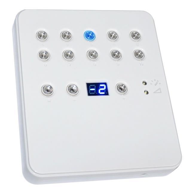
6 TOP FACE OF THE INTERFACE 19 : Mini USB connector (PC) / 5V. DC Scene triggering buttons: 20: Scene 1 On/Off 21: Scene 2 On/Off 22: Scene 3 On/Off 23: Scene 4 On/Off 24: Scene 5 On/Off 25: Scene 6 On/Off 26: Scene 7 On/Off 27: Scene 8 On/Off 28: Scene 9 On/Off 29: Scene 10 On/Off Command buttons: 30: Mode selection (trigger, speed, dimmer) 31: - decrease values 32: + increase values Display and LED: 33: Current mode LED 34: 7-segment LED display SELECTING MODE BUTTON Press the Mode button to select a mode between speed, dimmer or trigger LED 1 and 2 OFF : Trigger Mode. LED 1 ON only : Speed mode. LED 2 ON only : Dimmer mode. ( works on Dimmer or RGB channels) +/- BUTTONS OPERATION: Trigger mode: + and buttons allows to choose a different scene. You have to hold + and buttons for 2 seconds to validate the selection and play the new scene. Speed mode: + and buttons allows to increase or decrease the speed of the current scene from -9 to 9. Dimmer mode: + and buttons allows to increase or decrease the dimmer of the current scene from -9 to 9. LED 7-SEGMENTS DISPLAY OPERATION: Display the number of the playing scene and the mode (speed/dimmer) value. 00: Stand Alone mode running. No scene is playing. All DMX channels are set to 0. PC: The interface is connected to the computer and software controlled. In trigger mode, the 7 segment display gives the current scene number. The 00 value indicates that no scene is playing and the SLIM DMX interface send nulls (0x00) on all output DMX channels. In speed mode, the display indicates the speed of the current scene, values are between -9 and 9. In dimmer mode, the display indicates the general intensity, values are between -9 and 9. 5
7 LED 7-SEGMENTS SLEEP OPTION: It s possible to activate the sleep option in the software. This will turn off the display after 4 seconds of inactivity on the interface s buttons. Option available in the standalone window of the software EXTERNAL TRIGGERS OPERATION: Connect the pins to 5V following these combinations: 01 = A ; 02 = B ; 03 = AB ; 04 = C ; 05 = AC ; 06 = BC ; 07 = ABC ; 08 = D ; 09 = AD ; 10 = BD ; 11 = ABD ; 12 = CD ; 13 = ACD ; 14 = BCD ; 15 = ABCD. By default, the interface gives 4 external contacts (01, 02, 04, 08). To obtain 15 external contacts, you have to use a demultiplexing interface in order to go from 4 to 15 possible combinations. INFRA RED TRIGGERS OPERATION: An external module with an Infra Red receiver is necessary. It can be connected to the following pins: GND (pin 1 or 10) + 5V. DC out (pin 2) + IR Signal (pin 11). 6
8 INTERFACES MASTER/SLAVE CONNECTION When multiple interfaces are connected with USB, the standalone mode allows to set them as Master/Slave. This mode allows to synchronise many interfaces and mutualize their standalone spaces combining the universes. (up to 32 standalone universes ) A single interface can be define as master, others are automatically set to slaves. Triggers operated on the master interface are passed on slaves. However slaves are not synchronized on play time and keep individual control. Consequently slaves can trig and play different scenes. The master acts like a general remote imposing triggering to the slaves. Master/Slave mode allows to synchronize scenes and trigger actions of several interfaces together. To use interfaces as Master/Slave, you have to connect the interfaces each other s from the screw terminals. You need to connect together the pins M/S Data, M/S CLK and GND, as following: Interfaces configured as slave will strictly follow the clock, triggers and information providing by the master interface. Only one master interface at a time. 7

9 SETTING OF THE MASTER/SLAVE INTERFACES When multiple interfaces are connected with USB, the standalone mode allows to set them as Master/Slave. This mode allows to synchronize many interfaces and mutualize their standalone spaces combining the universes. (Up to 32 standalone universes) MODE MASTER/SLAVE «Default» The Stand Alone mode allows to choose 1 interface and to define this interface as Master from the interface list, it is possible to choose only one to be the Master, all the other one will be configured as slave by default. The interfaces are always ordered by serial number ascending order. A single interface can be define as master (lower serial number by default), others ones are automatically set to slaves. The master device play the current scene and synchronize the slave ones. The master forces the slave interfaces to play the same scene and the same step at the same time. The slave interfaces are forced to follow the master timings and triggers and they cannot act, play or trigger a scene independently. Master can trigger on and trigger off scenes of the slave interfaces. MODE MASTER/SLAVE «Desynchronized» An interface can be define as master, others are automatically set to slaves. All Triggers On or Off operated on the master interface are effective to slave ones. However slave interfaces are not synchronized with master's timing and keep individual controls. Consequently slaves can trigger and play different scenes at any time and not synchronized with the master ones. The master acts like a general remote imposing triggering to the slaves with total priority. Master can trigger ON and trigger OFF scenes of the slave interface. MODE MASTER/SLAVE «LTP» LTP means Latest Takes Priority. All interfaces are defined as slaves. Interfaces are not synchronized with timing and can trigger and play different scenes by itself. However triggers from an interface are passed to the others connected interfaces automatically and slave interfaces are forced to trigger the same scene. Here each interface acts like a general remote imposing triggering to the other slaves without synchronization. THE «NO RELEASE» Option This option is only available with LTP or DESYNCHRONIZED modes. Only triggers ON from the master interface are executed and effective. All triggers OFF are ignored and slaves interfaces keep playing their current scene. Each Slave interface can choose to release or not its scene depend on the option is activated or not. 8

10 DMX MERGING IN STANDALONE DMX Merging is available for the 1024 SLIM interfaces only, because it takes two DMX lines to make a merge. One DMX line must be turned into an input to capture the DMX signal provided by an external DMX board or by another DMX interface. The interface will merge the input signal with its own output signal by comparing DMX levels with a HTP filter. Merging is a solution to keep manual control on channels, using a DMX Board for example. It s also a way to create a multi-zones system by merging several interfaces on one final DMX line. DMX-B Must be turned into Input in the software Standard DMX Controller board The DMX Output is connected to the interface input LINE B mandatory DMX Output A is a merge between what the interface is playing and what is coming in the input line B. In the software s standalone window, select: DMX 1 OUT / DMX 2 IN and validate the merge option. 9

11 TRIGGERS CONFIGURATION WITH THE SOFTWARE The Stand Alone mode of the software enables to configure and personalize all the triggers. The information will be directly saved in the DMX interface memory with the memory writing function. SWITCH TO STANDALONE MODE When the device isn't connected to the software or has just been powered, it enters in Stand Alone mode after five (5) seconds. LED BUTTONS TRIGGER Standalone mode offers 10 buttons that represents the interface LED buttons. From the scene list of the standalone mode, you need to drag and drop a scene on any button to assign a button number. It's possible to replace a scene by another or to remove it by pulling it out of the list. INFRA RED REMOTE TRIGGERS Standalone mode offers up to 10 triggers with the Infra-Red remote. By selecting a scene in the list, it's possible to choose the remote button number (from 01 to 10) to trigger the scene. The other IR remote functions will work as well as the SLIM DMX interface. (Speed, dimmer, scene +, scene -, off). 10
 to trigger the scene. By default, the interface gives 4 external contacts (01, 02, 04, 08).")
12 EXTERNAL CONTACT TRIGGERS The Stand Alone mode offers up to 15 external possible triggers. By selecting a scene in the list, it's possible to choose the external contact number (from 01 to 15) to trigger the scene. By default, the interface gives 4 external contacts (01, 02, 04, 08). To obtain 15 external contacts, you have to use a demultiplexing interface in order to go from 4 to 15 possible combinations. DMX IN AND TRIGGERS VIA ANOTHER DMX SIGNAL The Stand Alone mode offers up to 512 DMX IN channel triggers and up to 255 DMX trigger values per channel. By selecting a scene in the list, it's possible to choose the channel number and the DMX value to trigger the scene. The scene will play when the value of the DMX channel is reached or exceeded. NOTE: This option is available with 1024 interfaces only One of the DMX lines must be turned into Input in software s options window. To reach this window go tu the software s menu : Tools > Options then click on the Device section as following : Device section Set DMX IN 11
13 TIME TRIGGERS WITH CLOCK AND CALENDAR The Stand Alone mode has an internal clock and a calendar. It's possible to assign a time trigger on every scene of the list. By selecting a scene on the list, it's possible to choose the start and end dates and hours and days of the week. You can thus create a lot of scenarios. CASE 1: Programming a unique trigger: Start schedule: The scene is triggered a single time at the given date and time. End schedule: The scene is stopped at the given date and time. CASE 2: Programming a repeating trigger: Start schedule: Date from which-one the scene will be playable according to the programmed triggers End schedule: Date after witch-one triggers will be ignored. With no End date, triggers are permanent 12
14 List of the months of the year The 12 check boxes represents the 12 months of the year (J) January to (D) December. The triggers will be performed on the activated months. Next, a daily hours range must be defined. Start and Stop days With a monthly repetition, you can choose the starting and stopping days for each chosen month. In this example triggers can happen between the 1 st and the 15 th of each chosen month. List of the days of the week The 7 check boxes represents the 7 days in a week. The triggers will be performed on the activated days only. Next, a time range must be defined. Start time The starting time is the time when the scene will be triggered for each chosen day. Of course chosen months, start and end schedule days are included. Release time The release time is the time when the scene will stop for each chosen day. Of course chosen months, start and end schedule days are included. The release time is not mandatory, if it s not defined, the scene will keep playing until another trigger event happens. (Like the triggering of another scene for example). NOTE: For a daily repetition, if the the starting time is later than the release time then the triggering will stopped the next day, even if the next day has not been selected. 13
15 SAVE AND RECOVER THE LAST SCENE AFTER THE POWER CUT OFF: Scenes with a start schedule and a stop schedule are set on a defined time space and can be memorized. The interface save the last scene played before the power cut off and recover it when the power is restored. The scene must obligatory include a start schedule and a stop schedule activate this option. SCENE TRIGGER PRIORITIES: When several scenes have the same time trigger (date + hour + minute), only the first scene in thelist will be triggered. The rest will be ignored 14


16 WALL MOUNTING INSTRUCTIONS The SLIM interface can we wall mounted on any place and surface. Wires are connected to the screw terminal block located on back of the SLIM housing. To fix the SLIM housing to a Europe, Asia or America standard wall switch box, there are 4 holes located behind the housing. Follow the mounting instruction to proceed. FOR EUROPE AND ASIA STANDARD: 60MM CENTER TO CENTER DISTANCE. FOR AMERICA STANDARD: 84MM CENTER TO CENTER DISTANCE. 15
, adjust the screw position to hold well the housing.")
17 BACK SIDE OF THE SLIM HOUSING SLIM Back side USA Wall switch Box USE THE SCREWS OF THE WALL SWITCH BOX TO OLD THE SLIM: 1 Insert the screws in the hole (vertical axe for USA wall boxes else horizontal axe ), adjust the screw position to hold well the housing. 2 Slide the housing to lock the screw in the slots 16
18 THE SECURE FIXING SL OT It's now easy to remove the SLIM from the wall by slinding it the oposit way to unlock the screws. To avoid and secure unexpected unlcoks, you can use the secure fixing slot. The secure fixing slot is use to ensure that housing stays on its wall mounted position. To do that it takes a special piece (plastic or metal ) to be use l ike a lock. We do not provite this part. This piece size should be 15mm x 20 mm maximum and need to receive a screw. You also need to create a slot in the wall to receive that lock piece. Special lock piece (Not provided) Locked position Thanks to that lock, it's now not possible to slide back the switch box screws to the plain holes of the SLIM case. IMPOSIBLE TO SLIDE FROM POSITION 2 TO POSITION 1 Datasheet - USB -DMX SLIM standalone wall Interface 17
STANDALONE INTERFACES USB-DMX 512 & 1024 CHANNELS V.1.0.5
 STANDALONE INTERFACES USB-DMX 512 & 1024 CHANNELS V.1.0.5 SUMMARY Hardware technical specifications... 4 Top Face of the 512 / 1024 channels interfaces... 5 LED 7-segments display operation:... 5 LED 7-segments
Stand Alone SLIM-DMX Interface
 Stand Alone SLIM-DMX Interface V.1.0.1 Summary Technical features of the interface P.02 General pinout and device's connector P.02 Bottom view of the interface P.03 Top view of the interface P.03 Interfaces
STANDALONE INTERFACE USB-DMX DIN V 1.6.1
 STANDALONE INTERFACE USB-DMX DIN V 1.6.1 SUMMARY Hardware Technical Specifications... 3 Dimension of the interface... 4 Front face... 4 Top face... 4 General pinout and device's connector... 5 External
STANDALONE INTERFACES USB-DMX 512 & 1024 CHANNELS V.1.1
 STANDALONE INTERFACES USB-DMX 512 & 1024 CHANNELS V.1.1 SUMMARY Hardware technical specifications... 3 Front Face of the 512 / 1024 channels interfaces... 4 Side Faces of the 512 / 1024 channels interfaces...
Hardware technical specifications Front Face of the 512 / 1024 channels interfaces LED 7-segments display operation:...
 SUMMARY Hardware technical specifications... 4 Front Face of the 512 / 1024 channels interfaces... 5 LED 7-segments display operation:... 5 LED 7-segments Sleep option:... 6 selection Mode button... 6
Stand Alone 512 channels DIN-DMX Interface
 Stand Alone 512 channels DIN-DMX Interface V1.0.1 Summary Technical features of the interface P.02 General pinout and device's connector P.02 Interfaces Master/Slave connections P.03 Triggers configuration
INTERFACES USB-DMX 512 & 1024 CHANNELS V.1.0.5
 INTERFACES USB-DMX 512 & 1024 CHANNELS V.1.0.5 SUMMARY 512 and 1024 Channel USB to DMX interfaces... 3 Hardware technical specifications... 3 Front Face of the 512 / 1024 channels interfaces... 4 Rear
INTERFACES USB-DMX 1024 CHANNELS V.1.0.6
 INTERFACES USB-DMX 1024 CHANNELS V.1.0.6 SUMMARY 1024 Channels USB to DMX interfaces... 3 Hardware technical specifications... 3 Front Face... 4 Rear Face... 4 IR receiver and remote... 5 DMX-IN trigger
INTERFACES USB-DMX 512 CHANNELS V.1.0.6
 INTERFACES USB-DMX 512 CHANNELS V.1.0.6 SUMMARY 512 Channel USB to DMX interfaces... 3 Hardware technical specifications... 3 Front Face of the interface... 4 Rear Face interface... 4 IR receiver and remote...
512 channels WIFI-DMX Interface
 512 channels WIFI-DMX Interface V.1.0.2 Summary Technical features of the interface General pinout and device's connectors Front side of the interface Rear side of the interface Default Access Point Mode
Software and Hardware Data-sheet
 Software and Hardware Data-sheet V.1.0.5 Summary: P.1 General Information P.2 Standard DMX 512 installation P.2 Recommended DMX512 installation P.3 512 and 1024 Channel USB to DMX interfaces P.4 Front
LP32. Package Content: Small package + 1 USB cable + 1 USB to DMX Interface (3 Pin XLR)
") LP32 The package works only with the Led Player Software under restricted mode. It is our most economic package. MOQ required. Great products for simple project with few channels and product promotion.
LP32 The package works only with the Led Player Software under restricted mode. It is our most economic package. MOQ required. Great products for simple project with few channels and product promotion.
ArtDMX DMX control software V1.4
 User manual ArtDMX DMX control software V1.4 1 2 Table of contents : 1. How to start a new Project...6 1.1. Introduction...6 1.2. System Requirements...6 1.3. Installing software and drivers...7 1.4. Software
lumentouch SPECIFICATION SHEET Client: Project name: Order #: Type: Qty: FEATURES AND BENEFITS PACKAGE CONTENT HOW TO ORDER LTO
 Client: Project name: Order #: Type: Qty: FEATURES AND BENEFITS Flat wall mounted lighting controller Universal mounting plate compatible with any electrical backbox MINI-USB connection for software programming
Сенсорный DMX контроллер STICK-DE3
 Сенсорный контроллер STICK-DE3 +7 (495) 510-71-29 +7 (495) 510-71-52 ps@planeta-sveta.ru www.planeta-sveta.ru Sunlite Touch-sensitive Intelligent Control Keypad Ref. STICK-DE3 Page 1/4 Technical datasheet
STICK-KE1. Sunlite Touch Sensitive Intelligent Control Keypad. Overview
 STICK-KE1 Sunlite Touch Sensitive Intelligent Control Keypad Overview This complete stand alone wall-mounted DMX controller is the perfect answer to interior lighting control expectations. Along with a
**CHECK PIN CONFIGURATIONS. APPLYING POWER TO THE DMX INPUT WILL DAMAGE THE CONTROLLER**
 Page 1 EASY INSTALLATION 1. Mount an electrical box inside the wall The controller can be installed in any standard electrical backbox. If you use a double size box, you can insert the power supply inside.
Installation Instructions for the RGB DMX Stick 3 Controller
 Installation Instructions for the RGB DMX Stick 3 Controller #RGB-DMX-CONT-STICK3 Installing the Controller 1. Mount an electrical box inside the wall The controller can be installed in any standard electrical
Installation Instructions for the RGB DMX Stick 3 Controller
 Installation Instructions for the RGB DMX Stick 3 Controller #RGB-DMX-CONT-STICK3 1. Mount an electrical box inside the wall The controller can be installed in any standard electrical backbox. If you use
IN LIGHTING CONTROL DMX EP-TOUCH-1 CONTROLLER THE INDUSTRY STANDARD. Flat wall mounted lighting controller. State of the art design and technology
 THE INDUSTRY STANDARD IN LIGHTING CONTROL DMX EP-TOUCH-1 CONTROLLER Flat wall mounted lighting controller State of the art design and technology Ideal for LED, RGB and DMX lighting Stand alone touch sensitive
Настенный DMX контроллер STICK + WiFi
 Настенный DMX контроллер STICK + WiFi +7 (495) 510-71-29 +7 (495) 510-71-52 ps@planeta-sveta.ru www.planeta-sveta.ru Sunlite Touch-sensitive Intelligent Control Keypad Ref. STICK-KE1 Page 1/4 128 mm Touch-sensitive
light-drive elite Setup Manual
 light-drive elite Setup Manual www.ecue.de light-drive elite - Setup Manual e:cue control GmbH An OSRAM Company Rev. 1_06/2009 light-drive elite - Setup Manual table of contents 1. Device Overview...4
Pro Series LED Controllers Part numbers: pro-4-in-1-receiver, dim-pro-knob-us-w dim-pro-knob-wa, dim-pro-knob-rgb, rgbw-pro-touch, rgb-pro-remote
 11235 West Bernardo Court, Suite 102 San Diego, CA 92127 888-880-1880 Fax: 707-281-0567 EnvironmentalLights.com Pro Series LED Controllers Part numbers: pro-4-in-1-receiver, dim-pro-knob-us-w dim-pro-knob-wa,
STICK-KE2. Sunlite Touch Sensitive Intelligent Control Keypad. Overview
 STICK-KE N I C O L A U D I E ARCHITECTURAL Sunlite Touch Sensitive Intelligent Control Keypad Overview A B C D E This truly simple controller features an on/off button at the top, buttons to choose from
REX F-0-9 Standalone or Access Controller
 REX F-0-9 Standalone or Access Controller Power supply The controller need s external power supply to operate. The Spider W40 power supply is sufficient to power two controllers and two 12V electric strikes
705 INSTALLATION MANUAL
 705 INSTALLATION MANUAL 2 Table of Contents Features...03 Specifications...04 Quick - Start...05 Remote Control...07 Hardware Installation...10 705 Models Additional Info...14 Owner s Record...15 3 Features
DMX-RGBW-128C. Overview
 Page 1 of 10 RGW128C Overview Mode Current scene (1 8) Next scene On / Off Previous scene SPECIFICATIONS OS REQUIREMENTS SOFTWARE OUTPUT PROTOCOL CHANNELS 128 APPEARANCE CONNECTIONS INPUT POWER CERTIFICATIONS
Quick Reference Guide
 LΩGIC 16X36 Quick Reference Guide About this Guide Disclaimer The LΩGIC 16X36 Quick Reference Guide (QRG) only contains the product s connection and mounting information, as well as the menu options and
VBAR 270. User Manual. Version 1.2
 VBAR 270 User Manual Version 1.2 VBAR 270 User Manual Page 1of 19 Introduction Thank you for purchasing VBAR 270. VBAR 270 is a LED light fixture for professional use. Using the RGB color mixing technology
STICK-DE3. Sunlite Touch Sensitive Intelligent Control Keypad. Overview
 STICK-DE3 Sunlite Touch Sensitive Intelligent Control Keypad Overview The feature rich lighting controller has been designed to provide a control solution for the most demanding of projects, whilst maintaining
Full Color Digital Scouting Camera. User s Manual Scouting Camera SG860C-HD
 Full Color Digital Scouting Camera User s Manual Scouting Camera SG860C-HD Content 1 Instruction...1 1.1 General Description...1 1.2 Application... 2 1.3 Camera Interface... 2 1.4 Saving Images or Videos...
SENSA DMX CONTROLLER KIT SAP code Pre-wired DMX Controller kit for DIN rail mounting
 Application Stand alone DMX Controller kit for the control of LED luminaires, pre-wired and ready for use. The Sensa DMX Controller uses the DMX 512 protocol to control LED luminaires. The Sensa software
Wireless DMX Control. Show Performer DMX Controller. Stage Desk 48 DMX Controller
 Wireless DMX Control SRC-260 Each unit is a transmitter and receiver based on its Dip settings. Connect a DMX 512 standard controller to the SRC-260 and set another SRC-260 set in receivers mode down range
PRODUCTS: CONTROLLERS
 PRODUCTS: CONTROLLERS 2009/US Impact Lighting Inc. All rights reserved. Impact Lighting Inc. Reserves the right to change specifications without notice. 118 CONTROLLERS 2 BUTTON MODE CHANGING RGB CONTROLLER
Colour Change Driver All RGB luminaires are supplied complete with RJ45 plug for simple connection into a colour change driver.
 LED Controls A whole new dimension in lighting is now available with LEDs. The ability to dynamically change colour enables the designer to create effects never seen or experienced before. As the colour
1020 / 1022 INSTALLATION MANUAL
 1020 / 1022 INSTALLATION MANUAL 2 Table of Contents Features...03 Specifications...04 Quick - Start...05 Remote Control...07 Hardware Installation...10 1020TSV, 1022TSV, 1020YV, 1022YV, 1020TSH, 1022TSH
TABLE OF CONTENTS 1. Safety Instructions 2. Technical Specifications 3. Installation 4. How to Connect the Fixture 5. DMX512 Connections 6.
 TABLE OF CONTENTS 1. Safety Instructions 2. Technical Specifications 3. Installation 4. How to Connect the Fixture 5. DMX512 Connections 6. How to Set the Unit 7. DMX Configuration 8. IR Remote Control
LED Controls. Lighting Controls. LED Controls
 Lighting Controls A whole new dimension in lighting is now available with LEDs. The ability to dynamically change colour enables the designer to create effects never seen or experienced before. As the
Infrared Digital Scouting Camera User s Manual Scouting Camera SG560K-8mHD
 Infrared Digital Scouting Camera User s Manual Scouting Camera SG560K-8mHD Content 1 Instruction... 1 1.1 General Description... 1 1.2 Application... 1 1.3 Camera Interface... 2 1.4 Saving Images or Videos...
ColourChaser Touch. Installation Guide
 ColourChaser Touch Installation Guide Dimensions C I S 110 29 72 Ø 4.5 56 85 I 2 3 4 100 77 ColourChaser Touch - Dimensions in mm Bracket - Dimensions in mm 2 Philips ColourChaser Touch Manual Content
E600 VX01 Installation guide
 E600 VX01 Installation guide illuminfx Dimensions 2007 Viso Systems ApS, Denmark All rights reserved. No part of this manual may be reproduced, in any form or by any means, without permission in writing
CW-WW LEDWash USER MANUAL
 LEDWash CW-WW USER MANUAL 1 1.BEFORE YOU BEGIN What is included Ø 1 x Fixture Ø 1 x Power cable with plug Ø 1 x User Manua Unpacking Instructions Immediately upon receiving a fixture, carefully unpack
DMX-Player L MK2. User Manual
 DMX-Player L MK2 User Manual DMX-Player L MK2 2 Description The DMX-Player L MK2 is a DMX Stand-Alone Player, designed for several tasks. Various programmable DMX-Programs can be stored in the In the DMX-Player
>daisy. Daisy-ON OUTDOOR / UNDERWATER USE. Daisy-IN INDOOR USE. Daisy-OUT INDOOR / OUTDOOR USE
 >daisy Daisy-ON OUTDOOR / UNDERWATER USE Daisy-IN INDOOR USE Daisy-OUT INDOOR / OUTDOOR USE The three-piece LED series is a small size high quality range of projectors for indoor and outdoor applications.
Stick 2 (STICK-GU2) Sunlite Touch-Sensitive Intelligent Control Keypad Getting Started Guide
 Sunlite Touch-Sensitive Intelligent Control Keypad Getting Started Guide") 11235 West Bernardo Court, Suite 102 San Diego, CA 92127 888-880-1880 Fax: 707-281-0567 EnvironmentalLights.com Kit STICK-GU2 Stick 2 (STICK-GU2) Sunlite Touch-Sensitive Intelligent Control Keypad Getting
11235 West Bernardo Court, Suite 102 San Diego, CA 92127 888-880-1880 Fax: 707-281-0567 EnvironmentalLights.com Kit STICK-GU2 Stick 2 (STICK-GU2) Sunlite Touch-Sensitive Intelligent Control Keypad Getting
4 Channel DMX Driver Instruction Manual
 LEDstuff.co.nz 4 Channel DMX Driver Instruction Manual Quality LED Lighting Products The LEDstuff 4 Channel DMX Driver is a flexible module that is an ideal addition to an existing home automation or lighting
ActiveSite. Color Dial Pro. Product Guide
 ActiveSite Color Dial Pro Product Guide Easily configure and control LED light shows is an Ethernet-based, stand-alone lighting controller and interface for intelligent RGB and intelligent white (iw) LED
PAR56 10MM UV LED PAR. user manual
 PAR56 10MM UV LED PAR user manual Musikhaus Thomann e.k. Treppendorf 30 96138 Burgebrach Germany Telephone: +49 (0) 9546 9223-0 E-mail: info@thomann.de Internet: www.thomann.de 03.12.2012 Table of contents
Infrared Digital Scouting Camera. User s Manual Covert Deuce
 Infrared Digital Scouting Camera User s Manual Covert Deuce Content 1 Instruction... 1 1.1 General Description... 1 1.2 Application... 1 1.3 Camera Interface... 1 1.4 Saving Images or Videos... 3 2 Cautions...
Product and Applications Description. Example of Operation. Installation Instructions WARNING. Note. Application Programs
 Product and Applications Description Example of Operation dimmer UP 525/11 load circuit AC 230 V L1 N The dimmer UP 525/11 is a dimming actuator for mounting in box mounts (a.o. 60 mm Ø, 60 mm depth).
Xenon Flash Digital Scouting Camera. User Manual SG565F-14mHD
 Xenon Flash Digital Scouting Camera User Manual SG565F-14mHD Content 1 Instruction... 1 1.1 Camera Body Interfaces... 1 1.2 General Description... 2 1.3 Application... 2 1.4 Shooting Information Display...
Safety. Features 1 ID: Make all the connections before you plug in the main power. DMX512 Controllable and RDM Configurable
 Features DMX512 Controllable and RDM Configurable Designed for driving LED strips through 6 high power 12 and 24 Volts output units available Easy addressing interface (physical switches and RDM) Isolated
SUNLITE is a trademark of Bruno Nicolaudie. WINDOWS is a trademark of the MICROSOFT CORPORATION. All rights reserved. No parts of this work may be
 SUNLITE is a trademark of Bruno Nicolaudie. WINDOWS is a trademark of the MICROSOFT CORPORATION. All rights reserved. No parts of this work may be reproduced in any form or by any means - graphic, electronic,
V2403 Quick Installation Guide
 V2403 Quick Installation Guide Edition 1.0, September 2015 Technical Support Contact Information www.moxa.com/support Moxa Americas: Toll-free: 1-888-669-2872 Tel: 1-714-528-6777 Fax: 1-714-528-6778 Moxa
User Manual INTRODUCTION SAFETY INFORMATION BACK PANEL DIAGRAM. Please read the instructions carefully and before use.
 User Manual ORION Cyclops 2 [ORFX4] INTRODUCTION Welcome to the Orion ORFX4 Cyclops2 9-channel DMX lighting fixture. Compact and lightweight, it is suitable for a wide range of party, nightclub and entertainment
CP 64 BD15 CP 64 PD15
 COLOR PAR 64 CP 64 BD15 CP 64 PD15 User Manual Please read the instruction carefully before use Contents 1. Safety Instruction...2 2. Technical Specification...3 3. Installation...4 4. DMX Address Setting...4
Eternal Lighting. Premier150 Spot. User Manual
 Eternal Lighting Premier150 Spot User Manual Introduction: Thank you for your purchase of the Premier150 Spot. When unpacking and before disposing of the carton, check there is no transportation damage
Neets Control QueBec P/N#: P/N#: User Manual
 Neets Control QueBec P/N#: 310-0011 P/N#: 310-0012 User Manual Foreword The purpose of this document is to describe how to install and configure the Neets Control QueBec II and Neets Control QueBec III.
lighting control
 lighting control www.visualproductions.nl WIN MAC LINUX CueluxPro CueluxPro is an advanced and scalable lighting control application. The software is designed to control medium to large lighting installations,
IN LIGHTING CONTROL DMX EP-TOUCH-3 CONTROLLER THE INDUSTRY STANDARD 78% Flat wall mounted lighting controller. State of the art design and technology
 THE INDUSTRY STANDARD IN LIGHTING CONTROL DMX EP-TOUCH-3 CONTROLLER Flat wall mounted lighting controller State of the art design and technology Ideal for LED, RGB and DMX lighting Stand alone touch sensitive
LED Accu Penta 9x12W RGBWAU
 Manual LED Accu Penta 9x12W RGBWAU Table of contents 1. Safety instructions... 3 1.1. FOR SAFE AND EFFICIENT OPERATION... 3 1.2. Additional Information for safety... 4 2. Introduction... 5 2.1. Statement...
10W LED PIN SPOT. User Manual LED-PS10D W. Innovation, Quality, Performance. Professional Entertainment Technology 11-
 Innovation, Quality, Performance 11-10W LED PIN SPOT LED-PS10D W User Manual Professional Entertainment Technology TABLE OF CONTENTS 1. Safety Instruction 2. Technical Specification 3. Installation 4.
STAGE TRI-PAR 18TC CP-18TC. User Manual. Please read the instructions carefully before use
 STAGE TRI-PAR 18TC CP-18TC User Manual Please read the instructions carefully before use TABLE OF CONTENTS 1. Safety Instructions 2. Technical Specifications 3. How to Set the Fixture 4. How to Control
700/702 INSTALLATION MANUAL
 700/702 INSTALLATION MANUAL 2 Table of Contents Features 03 Specifications 04 Quick Start..05 Remote Control.07 Capacitive Touch..10 Hardware Installation 11 700CSH / 702CSH / 700TSH / 702TSH / 700YH /
DMX 2X1 / 3X1 MERGER USER GUIDE Pg 1
 DMX 2X1 / 3X1 MERGER USER GUIDE Pg 1 DMG OVERVIEW The DMG is a 1~3 input 1 output DMX merger with versatile uses. Combines two or more DMX signals or universes into one universe, by a selected mode type;
Infrared Digital Scouting Camera. User s Manual Scouting Camera SG560P-8M
 Infrared Digital Scouting Camera User s Manual Scouting Camera SG560P-8M Content 1 Instruction...1 1.1 General Description...1 1.2 Application...1 1.3 Camera Interface... 2 1.4 Saving Images or Videos...
36LEDs Par Light. User Manual
 36LEDs Par Light User Manual 1.BEFORE YOU BEGIN What Is Included 1 x 36LEDs Par Light 2 x Remote Controls 1 x User Manual 1 x Holder Unpacking Instructions Thank you for purchasing the 36LEDs Par Light
The user connects our device to his WiFi Network. Please see the instructions for connecting to the WiFi at
 AL-DALI-DMX-Wiz Atx Led Consultants Inc 815-A Brazos #326 Austin Tx, 78701 512 377 6052 http://atx-led.com Lighting Control Cloud Interface for Apps, Alexa, Google Home, IFTTT DALI, DMX and 0-10v outputs
Contents Safety precautions Product components Optional accessories Names of each parts Product Dimension Cables and Connectors Power Connection
 Contents Safety precautions Product components Optional accessories Names of each parts Product Dimension Cables and Connectors Power Connection LAN Connection RS485 Connection Relay Connection Digital
700TSU INSTALLATION MANUAL
 M 700TSU INSTALLATION MANUAL 2 Table of Contents Features...03 Specifications...04 Quick-Start...05 Remote Control...07 Hardware Installation...10 Software Installation...14 Touch Screen Driver Installation
RST ROOM TEMPERATURE TRANSMITTER. Mounting and operating instructions
 Mounting and operating instructions Table of contents SAFETY AND PRECAUTIONS 3 PRODUCT DESCRIPTION 4 ARTICLE CODES 4 INTENDED AREA OF USE 4 TECHNICAL DATA 4 STANDARDS 4 OPERATIONAL DIAGRAM 5 WIRING AND
V2 LED SOFTLIGHT USER GUIDE
 with On-Board Controls v2.0 V2 LED SOFTLIGHT USER GUIDE X2 Panel 2X2 Panel Pro-Panel LED User Guide TABLE OF CONTENTS What s in the Box... 2 Features... 3 Cautions & Warnings... 3 Operations, Storage &
4-CHANNEL DMX WALL-MOUNTED CONTROLLER
 4-CHANNEL DMX WALL-MOUNTED CONTROLLER USER GUIDE 9584 - Sept 2011 - Version 2 English CTLTAPE - 4-channel DMX wall-mounted controller Page 2 CTLTAPE - 4-channel DMX wall-mounted controller English 1 -
Allows full two way communication from any USB or RS232 port to an SPI device.
 RS232 & USB to SPI Bi-Directional Converter: RS232SPI or USBSPI The Big Deal Allows Bi-Directional communication between USB or RS232 to SPI Easy-to-use, quick-loading GUI and API objects for programmers
LED PANEL. User Manual Please read the instructions carefully before use LED-7TC. Innovation, Quality, Performance 15-
 LED PANEL LED-7TC Innovation, Quality, Performance User Manual Please read the instructions carefully before use 15- 9. Fixture Cleaning TABLE OF CONTENTS 1. Safety Instructions 2. Technical Specifications
User s manual. Easy Scan XT3 LED
 User s manual Easy Scan XT3 LED Table of content 1. Safety instructions... 3 2. Before you begin... 4 2.1. What is included... 4 2.2. AC Power... 4 3. Introduction... 4 3.1. Features... 4 4. Product overview...
LED DMX Controller Stick DE3 - User Manual
 ED Controller Stick DE3 - User Manual Item no.: white C-007-005 Item no.: black C-007-105 1. Product Description The ED Controller Stick DE3 is a multiple ED Controller with glas touchpanel and are sending
ACR89 Handheld Smart Card Reader Technical Specifications. Datenblatt / Specifications
 Datenblatt / Specifications ACR89 Handheld Smart Card Reader Technical Specifications idvation GmbH Otto-Hesse-Straße 19 / T5 Phone +49 6151 9926567 D-64293 Darmstadt Fax +49 6151 3689296 info@idvation.com
Architectural Lighting Controller AC612 XU User Manual
 Architectural Lighting Controller AC612 XU User Manual Architectural Lighting Controller AC612 XU User Manual The ELC Architectural Lighting Controller AC612 XU is available in several variations; The
TCNM-ACBB1 Installation Manual
 The TCNM-ACBB1 is a connection box that can be used as an accessory to facilitate system connections for installation and device replacement of several Banner family reading devices. System cabling is
Party Par. User Manual. Order codes: EQLED015 - Black housing EQLED015B - Polished housing
 Party Par User Manual Order codes: EQLED015 - Black housing EQLED015B - Polished housing Safety advice WARNING FOR YOUR OWN SAFETY, PLEASE READ THIS USER MANUAL CAREFULLY BEFORE YOUR INITIAL START-UP!
SLESA-UE7 Quick Start Guide
 SLESA-UE7 Quick Start Guide 11235 West Bernardo Court, Suite 102 San Diego, CA 92127 888-880-1880 Fax: 707-281-0567 EnvironmentalLights.com You will need to install Easy Stand Alone Pro (ESA Pro) or Easy
ATG Electronics DynColor 500-SL RGB DMX Controllers
 Page 1 of 20 ATG Electronics DynColor 500-SL RGB DMX Controllers USER GUIDE Part Number HCD-SL500-000000-0U NOTE: This user guide is to explain the steps necessary to use the specified and assure peak
ADVANCED ultrasonic sensors with 2 switching outputs. Dimensioned drawing
 Dimensioned drawing en 2-214/2 5124879 25 4mm 15 13mm 15-3 V DC We reserve the right to make changes DS_HTU418BX3LT4_en_5124879.fm Largely surface-independent function, ideal for the detection of liquids,
Technical Specifications
 Technical Specifications ACF30 Floppy Bay Smart Card Reader Advanced Card Systems Ltd. Website: www.acs.com.hk Email: info@acs.com.hk Table of Contents 1.0. Introduction... 3 2.0. Features... 4 3.0. Supported
LED W RGBA User Manual
 LED- 245-1W RGBA User Manual Please read the instructions carefully before use CONTENTS 1. Safety Instructions...2 2. Technical Specifications...3 3. How To Set The Unit...4 3.1 Control Panel...4 3.2 Main
LED MOVING HEAD FLEX BEAM K8 RGBW. User Manual. Please read the instruction carefully before use
 LED MOVING HEAD FLEX BEAM K8 RGBW 1 User Manual Please read the instruction carefully before use CONTENTS 1. Safety Instructions... 3 2. Technical Specifications... 4 3. How To Set The Unit... 5 3.1 Front
LED PANEL. User Manual Please read the instructions carefully before use LED-212RGB TABLE OF CONTENTS. 1. Safety Instructions
 TABLE OF CONTENTS LED PANEL 1. Safety Instructions 2. Technical Specifications 3. Installation 4. How to set the unit 5. How to control the fixture 6. DMX512 Configuration 7. DMX512 Connections 8. Troubleshooting
Fiber Optic Illuminators
 Fiber Optic Illuminators Illuminators are the light source for your fiber optic system. We offer many different types for different uses. If you are looking to do a project in your pool, spa, garden or
Copyright Daslight, all rights reserved
 User Manual Index Driver and Install... 5 Package contents... 5 System requirements... 5 Installation and update of the drivers... 5 Software installation and update... 7 SETUP mode... 8 Create a new project...
WELCOME. Network: Only use Shielded CAT5 cable for network communication.
 WELCOME ievo would like to thank you for purchasing our product. This manual is designed to make your installation of our superior biometric reader quick, easy and efficient. Please ensure you check all
w w w. p r o l i g h t. c o. u k STAGE PAR 64
 w w w. p r o l i g h t. c o. u k STAGE PAR 64 Order code: LEDJ40 (Black) Order code: LEDJ41 (Polished) Order code: LEDJ42 (Black) Order code: LEDJ43 (Polished) Order code: LEDJ44 (Black) Order code: LEDJ45
Operation Manual. FreeStyle 31/21 LED LED-151X
 Operation Manual FreeStyle 31/21 LED LED-151X Part No. 3100104 Rev C 01-31-2018 FreeStyle 31 & 21 LED Systems SYS-F31U FreeStyle 31 LED DMX System, Univ SYS-F21U FreeStyle 21 LED DMX System, Univ Each
1029 INSTALLATION MANUAL
 1029 INSTALLATION MANUAL 2 Table of Contents Features 03 Specifications 04 Quick Start..05 Remote Control.07 Capacitive Touch..10 Hardware Installation 11 1029CNH / 1029CNV / 1029TNH / 1029TNV Models Additional
Artistic Licence. matisse d4 dmx. User Guide. matisse d4 dmx User Guide. Version 1-1
 Artistic Licence matisse d4 dmx User Guide Version 1-1 Please read these instructions before using the product. This product has been designed & manufactured for professional use only. It should only be
Mini Bluetooth Mesh Controllers
 Part number: dim-mini-bt-mesh, tw-mini-bt-mesh, rgb-mini-btmesh, rgbw-mini-bt-mesh The from Environmental Lights give you the capability to wirelessly control your LED lights. When paired with the Light
SINGLE COLOR TRULUX STANDARD TRULUX HIGH OUTPUT TRULUX SPEC GRADE. Description / Performance. Description / Performance. Description / Performance
 8 SINGLE COLOR TRULUX STANDARD Description / Performance Build an economical and versatile layered lighting system with Standard Trulux. Light output ranges from 100-155 lumens per foot, with run lengths
RXTP ROOM TEMPERATURE
 ROOM TEMPERATURE CONTROLLER WITH PI CONTROL Mounting and operating instructions Table of contents SAFETY AND PRECAUTIONS 3 PRODUCT DESCRIPTION 4 ARTICLE CODES 4 INTENDED AREA OF USE 4 TECHNICAL DATA 4
Dual channel temperature logger with two voltage inputs 0-5V Instruction Manual
 LOGGER S0541 Dual channel temperature logger with two voltage inputs 0-5V Instruction Manual Instruction Manual for use of S0541 logger Instrument is designed for measurement and record of temperature
Artistic Licence. Rail-DALI-DMX. User Guide. Rail-DALI-DMX User Guide. Version 1-5
 Artistic Licence Rail-- User Guide Rail-- User Guide Version 1-5 Please read these instructions before using the product. This product has been designed & manufactured for professional use only. It should