v1.10 Closer to Real, User s Manual RX-28 Dynamixel ROBOTIS CO.,LTD.
|
|
|
- Juliet Barrett
- 6 years ago
- Views:
Transcription


1 v1.10 Dynamixel Closer to Real, User s Manual RX-28 ROBOTIS CO.,LTD.
2 Contents 1. Introduction What is Dynamixel? Strong Points of Dynamixel Specifications of RX Installation How to Assemble Frames Assembling Connector Wiring Connection of Main Controller Communication with RX Overview of Communication Instruction Packet Status Packet (Return Packet) Control Table How to Use Packet Appendix 44 1
3 1. Introduction 1. What is Dynaimxel? 2. Strong Points of Dynamixel 3. Specifications of RX-28 2


4 1-1. What is Dynamixel? New Concept Dynamixel is a robot-only Smart Actuator with a new concept integrating speed reducer, controller, driver, network function, etc. into one module. Reduction Gear Controller Driver Network Dynamixel LINE UP We have Line up of several kinds of Dynamixel applicable numerously according to the kinds and characteristics of robots 3


5 All-round Combining Structure Dynamixel is built up with all-round combining structure and it is possible to connect one another with various forms. You can design a robot easily as if assembling a block toy by using option frame for Dynamixel Convenient Wiring Dynamixel is connected with Daisy Chain and it is easy to wire one another. Network Dynamixel with a unique ID is controlled by Packet communication on a BUS and supports networks such as TTL, RS485, and CAN depending on the type of model. 4
6 1-2. Strong Points of Dynamixel Torque In spite of the compact size, it generates relatively big Torque by way of the efficient speed reduction. Close Control It can control location and speed with the resolution of Elasticity Setting It can set up the extent of elasticity when controlling position with Compliance Driving. Position, Speed It can read the current position and speed. Communication It is easy to wire since it is connected with Daisy chain, and up to 1M BPS of communication speed is supported. Distribution Control Since the main processor can set speed, position, compliance, torque, etc. simultaneously with a single command packet, it can control several Dynamixels with a little resource Physical Intensity The main body is made of engineering plastic to withstand against strong external force. Efficiency against External Force Since a bearing is used at the last axis of the gear, the amount of efficiency reduction is minimal even if strong external force is applied to the axis. Safety Device It has the [Alarming] function, which notifies when internal temperature, torque, supplied voltage, etc. deviate from what the user has set, and the [Shut down] function, which allows it to cope with situation by itself. Status Indicator It informs the user of ERROR status via LED. 5
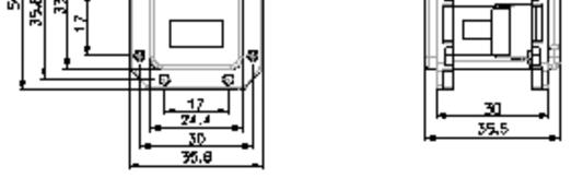
7 1-3. Specifications of RX-28 RX-28 Weight (g) 72 Dimension (mm) 35.6 x 50.6 x 35.5 Gear Reduction Ratio 1/193 Applied Voltage (V) at 12V at 16V Final Reduction Stopping Torque (kgf.cm) Speed (Sec/60 degrees) Resolution 0.29 Running Degree Voltage Max Current 300, Endless Turn 12V~16V (Recommended voltage: 14.4V) 1200mA Running Temperature -5 ~ +85 Command Signal Protocol Link (Physical) Digital Packet RS485 Asynchronous Serial Communication (8bit,1stop, No Parity) RS485 Multi Drop Bus ID 254 ID (0~253) Communication Speed 7343bps ~ 1 Mbps Sensing & Measuring Position, Temperature, Load, Input Voltage, etc. Material Quality Motor Standby Current Full Metal Gear, Engineering Plastic Body Maxon RE-MAX 50 ma 6
8 2. Installation 1. How to Assemble Fames 2. Assembling Connectors 3. Wiring 4. Connection of Main Controller 7
9 2-1. How to Assemble Frames Optional Frames RX-28 has the following optional frames. OF-28B OF-28S RXOF-28H 8


10 Horn RX-28 has the following kinds of Horns. Horn-28N Horn-28I Horn-28T Basic Supply Ball Bearing Trust washer Device Combination The below picture shows examples of combinations by using optional frames and horns. 9


 Forming Press the cable and terminal by using Wire Former.")


11 2-2. Assembling Connector Connector is assembled in the following order. 1) Striping Peel the coating of cable to the extent of 5mm approx. 2) Inserting Put the cable on the terminal like the left picture. 3) Forming Press the cable and terminal by using Wire Former. 4) Formed Wire 5) Assembling Combine the terminal to the cable tightly like the left picture. Solder the terminal and cable after Forming to get the more solid combination. Insert the terminal into 4P Molex connector. 6) Complete When inserting the terminal, be careful with the direction of the Molex connector. Terminals should be inserted in the same way as the left picture 10
12 2-3. Wiring Pin Assignment The pin assignment of a connector is as shown below. RX-28 can be run by linking with any one of two 4P connectors of RX-28 since they are connected Pin2Pin internally PIN1: GND PIN2: VDD (12V~21V) PIN3: D+ PIN4: D- PIN1: GND PIN2: VDD(12V~21V) PIN3: D+ PIN4: D- Wiring Wiring should be done Pin2Pin as shown below. By connecting as such, several RX-28s can be controlled on a BUS Caution Please pay special attention to avoid incorrect pin assignments in wiring. Otherwise, RX-28 may be damaged. 11
13 2-4. Connection of Main Controller Main Controller RX-28 uses the Multi-Drop Link method which connects several RX-28s to a Node by using Half Duplex UART. Thus, a Main Controller to run RX-28 must support RS485 UART. You can also design and use Main Controller by yourself. (Refer to the website ) Connection with PC If you want to control RX-28 with PC, you may control it via the Dynamixel-only controller or using the USB2Dynmixel. For further information, refer to the Dynamixel-only controller manual or the USB2Dynmixel manual. Serial cable Dynamixel-only Controller Power line USB PORT USB2Dynamixel Power line Connection with UART To control RX-28 with a personally made Main Controller, the signal of Main Controller UART should be converted into RS485 type signal. The following is a recommended circuit diagram. 12
14 The power of RX-28 is supplied via Pin1(-), Pin2(+). (The above circuit is built into Dynamixel-only controller.) In the above circuit diagram, the direction of data signal of TxD and RxD in the TTL Level is determined according to the level of DIRECTION 485 as follows: In case of DIRECTION485 Level = High: The signal of TxD is output to D+ and D-. In case of DIRECTION485 Level = Low: The signal of D+ and D- is output to RxD. Confirmation of The LED of RX-28 flickers once if the power is supplied to RX-28 properly via wiring. Connection Checking If the above steps are not performed successfully, recheck the pin assignment of the connector. If the pin assignment is right, check the allowable voltage and current of the power supply. Note Please check the current consumption when applying the power for the first time. The current consumption of RX-28 in the standby state is 50mA or less. 13
15 3. Communication with RX Overview of Communication 2. Instruction Packet 3. Status Packet 4. Control Table 5. How to Use Packet 14

16 3-1. Overview of Communication To control RX-28, communication should be established according to the protocol of RX- 28. RX-28 is driven by receiving binary data. Examples of programs for the transmission of this kind of data are described in detail in the User s Manual of the Dynamixel-only controller or the USB2Dynamixel. Thus, this manual describes only the method and protocol of communication used in RX-28 on the assumption that Main Controller can transfer binary data. Packet Main Controller and RX-28 communicate each other by sending and receiving data called Packet. Packet has two kinds: Instruction Packet, which Main Controller sends to control RX-28, and Status Packet, which RX-28 responses to Main Controller. Main Controller Instruction Packet Status Packet Role of ID ID is a specific number for distinction of each RX-28 when several RX-28s are linked to one bus. By giving IDs to Instruction and Status Packets, Main Controller can control only the RX-28 that you want to control Protocol RX-28 does the Asynchronous Serial Communication with 8 bit, 1 Stop bit, and None Parity. Caution If RX-28 with the same ID is connected, packet will collide and network problem will occur. Thus, set ID as such that there is no RX-28 with the same ID. Note ID of RX-28 is changeable. For this change, please refer to Changing IDs of Ex.2 and Ex.7. The factory default setting ID is 1. 15
17 3-2. Instruction Packet Instruction Packet is command data that Main Controller sends to RX-28. The structure of Instruction Packet is as follows: OXFF 0XFF ID LENGTH INSTRUCTION PARAMETER1 PARAMETER N CHECK SUM The meaning of each byte composing packet is as follows: 0XFF 0XFF This signal notifies the beginning of the packet ID It is the ID of RX-28 which will receive Instruction Packet. It can use 254 IDs from 0 to 253 (0X00~0XFD). Broadcasting ID : ID = 254 (0XFE) If Broadcast ID is used, all linked RX-28s execute command of Note Instruction Packet, and Status Packet is not returned. LENGTH It is the length of the packet. The length is calculated as the number of Parameters (N) + 2. INSTRUCTION This command gives an instruction to RX-28 and has the following types. Value Name Function No. of Parameters 0x01 PING No execution. It is used when controller is ready to recevie Status Packet 0 0x02 READ DATA This command reads data from RX x03 WRITE DATA This command writes data to RX-64 2 or more 0x04 REG WRITE It is similar to WRTE_DATA, but it remains in the standby state without being executed until the 2 or more ACTION command arrives. 0x05 ACTION This command initiates motions registered with REG WRITE 0 0x06 RESET This command restores the state of RX-64 to the factory default setting. 0 0x83 SYNC WRITE This command is used to control several RX-64s simultaneously at a time. 4 or more 16
18 PARAMETER0 N Parameter is used when Instruction requires ancillary data. For the usage of parameters, refer to 3-5 How to Use Packet CHECK SUM It is used to check if packet is damaged during communication. Check Sum is calculated according to the following formula. Check Sum = ~ ( ID + Length + Instruction + Parameter1 + Parameter N ) Where, ~ is the Not Bit operator. When the calculation result of the parenthesis in the above formula is larger than 255 (0xFF), use only lower bytes. For example, when you want to use Instruction Packet like the below ID=1 (0x01), Length= 5 (0x05), Instruction= 3 (0x03), Parameter1= 12 (0x0C), Parameter2= 100 (0x64), Parameter3= 170 (0xAA) Check Sum = ~ ( ID + Length + Instruction + Parameter1 + Parameter 3 ) = ~ [ 0x01 + 0x05 + 0x03 + 0x0C + 0x64 + 0xAA ] = ~ [ 0x123 ] // Only the lower byte 0x23 executes the Not operation. = 0xDD Thus, Instruction Packet should be 0x01, 0x05, 0x03, 0x0C, 0x64, 0xAA, 0xDD. 17
19 3-3. Status Packet (Return Packet) RX-28 executes command received from the Main controller and returns the result to the Main Controller. The returned data is called Status Packet. The structure of Status Packet is as follows: OXFF 0XFF ID LENGTH ERROR PARAMETER1 PARAMETER2 PARAMETER N CHECK SUM Each byte composing the packet means as below. 0XFF 0XFF ID This signal notifies the beginning of the packet. It is the ID of RX-28 which transfers Status Packet. LENGTH It is the length of Status Packet, the value of which is the number of Parameters (N) + 2. ERROR It displays the error status occurred during the operatio of RX-28. The meaning of each bit is described in the below table. Bit Name Contents Bit Bit 6 Instruction Error In case of sending an undefined instruction or delivering the action command without the reg_write command, it is set as 1. Bit 5 Overload Error When the curren load cannot be controlled by the set Torque, it is set as 1. Bit 4 Checksum Error When the Checksum of the transmitted Instruction Packet is incorrect, it is set as 1. When a command is out of the range for use, it is set as Bit 3 Range Error 1 When internal temperature of Dynamixel is out of the Bit 2 Overheating Error range of operating temperature set in the Control table, it is set as 1. Bit 1 Angle Limit Error When Goal Position is written out of the range from CW Angle Limit to CCW Angle Limit, it is set as 1. Bit 0 Input Voltage Error When the applied voltage is out of the range of operating voltage set in the Control table, it is as 1. 18
20 For example, when Status Packet is returned as below 0xFF 0xFF 0x01 0x02 0x24 0xD8 It means that the error of 0x24 occurs from RX-28 whose ID is 01. Since 0x24 is as binary, Bit5 and Bit2 become 1. In order words, Overload and Overheating Errors have occurred. PARAMETER0 N It returns data except ERROR. For the usage of parameters, refer to 3-5 How to Use Packet". CHECK SUM It is used to check if packet is damaged during communication. The below formula defines Check Sum. This formula is constructed in the same way as the Check Sum of Instruction Packet. Check Sum = ~ ( ID + Length + Error + Parameter1 + Parameter N ) 19
21 3-4. Control Table EEPROM Area RAM Area Control Table consists of data regarding the current status and operation, which exists inside of RX-28. The user can control RX-28 by changing data of Control Table via Instruction Packet. Address (hexadecimal) Name Description Access Initial Value (Hexadecimal) 0 (0X00) Model Number(L) Lowest byte of model number R 28 (0X1C) 1 (0X01) Model Number(H) Highest byte of model number R 0 (0X00) 2 (0X02) Version of Firmware Information on the version of firmware R - 3 (0X03) ID ID of Dynamixel RW 1 (0X01) 4 (0X04) Baud Rate Baud Rate of Dynamixel RW 34 (0X22) 5 (0X05] Return Delay Time Return Delay Time RW 250 (0XFA) 6 (0X06) CW Angle Limit(L) Lowest byte of clockwise Angle Limit RW 0 (0X00) 7 (0X07) CW Angle Limit(H) Highest byte of clockwise Angle Limit RW 0 (0X00) 8 (0X08) CCW Angle Limit(L) Lowest byte of counterclockwise Angle Limit RW 255 (0XFF) Highest byte of counterclockwise Angle 9 (0X09) CCW Angle Limit(H) RW 3 (0X03) Limit 11 (0X0B) the Highest Limit Temperature Internal Limit Temperature RW 80 (0X50) 12 (0X0C) the Lowest Limit Voltage Lowest Limit Voltage RW 60 (0X3C) 13 [0X0D) the Highest Limit Voltage Highest Limit Voltage RW 240 (0XF0) 14 (0X0E) Max Torque(L) Lowest byte of Max. Torque RW 255 (0XFF) 15 (0X0F) Max Torque(H) Highest byte of Max. Torque RW 3 (0X03) 16 (0X10) Status Return Level Status Return Level RW 2 (0X02) 17 (0X11) Alarm LED LED for Alarm RW 36 (0X24) 18 (0X12) Alarm Shutdown Shutdown for Alarm RW 36 (0X24) 24 (0X18) Torque Enable Torque On/Off RW 0 (0X00) 25 (0X19) LED LED On/Off RW 0 (0X00) 26 (0X1A) CW Compliance Margin CW Compliance margin RW 0 (0X00) 27 (0X1B) CCW Compliance Margin CCW Compliance margin RW 0 (0X00) 28 (0X1C) CW Compliance Slope CW Compliance slope RW 32 (0X20) 29 (0X1D) CCW Compliance Slope CCW Comliance slope RW 32 (0X20) 30 (0X1E) Goal Position(L) Lowest byte of Goal Position RW - 31 (0X1F) Goal Position(H) Highest byte of Goal Position RW - 32 (0X20) Moving Speed(L) Lowest byte of Moving Speed RW - 33 (0X21) Moving Speed(H) Highest byte of Moving Speed RW - 34 (0X22) Torque Limit(L) Lowest byte of Torque Limit RW ADD14 35 (0X23) Torque Limit(H) Highest byte of Torque Limit RW ADD15 36 (0X24) Present Position(L) Lowest byte of Current Position R - 37 (0X25) Present Position(H) Highest byte of Current Position R - 38 (0X26) Present Speed(L) Lowest byte of Current Speed R - 39 (0X27) Present Speed(H) Highest byte of Current Speed R - 40 (0X28) Present Load(L) Lowest byte of Current Load R - 41 (0X29) Present Load(H) Highest byte of Current Load R - 42 (0X2A) Present Voltage Current Voltage R - 43 (0X2B) Present Temperature Current Temperature R - 44 (0X2C) Registered Instruction Means if Instruction is registered RW 0 (0X00) 46 (0X2E) Moving Means if there is any movement R 0 (0X00) 47 (0X2F) Lock Locking EEPROM RW 0 (0X00) 48 (0X30) Punch(L) Lowest byte of Punch RW 32 (0X20) 49 (0X31) Punch(H) Highest byte of Punch RW 0 (0X00) 20
22 RAM and EEPROM Data in RAM area is reset to the initial value whenever the power is turned on while data in EEPROM area is kept once the value is set even if the power is turned off. Address It represents the location of data. To read data from or write data to RX-28, the user should assign an address where the data locates to Packet. Access RX-28 has two kinds of data: Read-only data, which is mainly used for sensing, and Read-and-Write data, which is used for driving. Initial Value In case of data in the EEPROM Area, the initial values on the right side of the above Control Table are the factory default settings. In case of data in the RAM Area, the initial values on the right side of the above Control Table are the ones when the power is turned on. Highest/Lowest Byte In the Control table, some data share the same name, but they are attached with (L) or (H) at the end of each name to distinguish the address. This data requires 16bit, but it is divided into 8bit each for the addresses (low) and (high). These two addresses should be written with one Instruction Packet at the same time. 21
23 3-4-1 Control Table Items ( EEPROM Area ) Model Number. Address 0, 1 (0x00, 0x01) In case of RX-28, the data value is 28 (0X001C). Firmware Version Address 2 (0x02) It represents the firmware version. ID Address 3 (0x03) It is a unique number to identify RX to 253 (0xFD) can be used for it and the factory default setting is 1. Baud Rate Address 4 (0x04) It represents the communication speed. 0 to 254 (0xFE) can be used for it. This speed is calculated by using the below formula. Speed (BPS) = / ( Data + 1 ) Data value per Baud Rate Data Set BPS Target BPS Tolerance % % % % % % % % % Note If the tolerance of Baud Rate is less than 3 %, there is no problem with communication. The initial value of Baud rate is 34 (0x22) (i.e., 57600bps). Return Delay Time Address 5 (0x05) It is the delay time that takes from the transmission of Instruction Packet until the return of Status Packet. 0 to 254 (0xFE) can be used, and the delay time per data value 1 is 2 usec. That is to say, if the data value is 10, 20 usec is delayed. The initial value is 250 (0xFA) (i.e., 0.5 msec). 22
24 Operating Angle Limit Address 6, 7, 8, 9 (0x06,0x07,0x08,0x09) It represents the allowed range of movement. The range for use is 0 to 1023 (0x3FF). Data 0 denotes 0 and Data 1023 (0X3FF) 300. Thus, the angle per data value 1 is about 0.3. Highest Limit Temperature Address 11 (0x0B) It is the highest limit of operating temperature. The range for use is 10 to 99 (0x10~0x63). If the internal temperature of RX-28 exceeds this range, Over Heating Error Bit (Bit2) of Status Packet is returned as 1 and Alarm is triggered as set in the addresses 17 and 18. The value is equal to the actual Celsius temperature. In other words, the initial value Data 80 (0x50) is 80. Caution Do not set The Highest Limit Temperature of RX-28 above the initial value of 80. If RX-28 is used at the temperature of 80 or higher, it may be damaged Lowest / Highest Address 12, 13 (0x0C, 0x0D) It is the operation range of voltage. 50 to 250 (0x32 ~ Limit Voltage 0x96) can be used. If Present Voltage (Address42) is out of the range, Voltage Range Error Bit (Bit0) of Status Packet is returned as 1 and Alarm is triggered as set in the addresses 17 and 18. Data value is 10 times larger than actual voltage. For example, the Lowest Limit Voltage Data of 80 means that the Lowest Limit Voltage is set as 8V. Max Torque Address 14, 15 (0x0E, 0x0F) It is the torque value of maximum output. 0 to 1023 (0x3FF) can be used. The value set to 0 means the Free Run state without torque. Max Torque is allocated to EEPROM (Addresses 14 and 15) and RAM (Addresses 34 and 35). When the power is turned on, EEPROM value is copied to RAM. In actual operation, the maximum torque is restrained by Torque Limit (Addresses 34 and 35) located in RAM. Data value represents the ratio of Torque output under the currently applied voltage. In other words, Data 1023 (0x3FF) means that RX-28 will use 100% of the maximum torque it can produce while Data 512 (0x200) means that RX-28 will use 50% of the maximum torque. For stopping torque value according to the state of voltage of RX-28, refer to 1-3 Specifications of RX
25 Status Return Level Address 16 (0X10) It decides how to return Status Packet. There are three ways like the below table. Address16 Return of Status Packet 0 No return against all instructions 1 Retrun only for the READ_DATA command 2 Return for all Instructions When Instruction Packet is Broadcast ID, Status Packet is not returned regardless of Status Return Level. Note When Instruction Packet is Ping, Status Packet is returned regardless of Status Return Level. Alarm LED Address 17 (0X11) It shows an error status occurred during operation through LED. Alarm LED is allocated with a bit according to each error content like the below table and it flickers when the bit is set as 1 and the corresponding error occurs. The function of each bit runs the logic of OR. That is to say, LED flickers even if 0X05 (binary ) is set and Input Voltage Error or Overheating Error occurs. LED stops flickering in two seconds when error occurs and is recovered to the normal state. Bit Name Contents Bit Bit 6 Instruction Error When undefined Instruction is transmitted or the Action command is delivered without the reg_write command Bit 5 Overload Error When the current load cannot be controlled with the set maximum torque Bit 4 Checksum Error When the Checksum of the transmitted Instruction Packet is invalid Bit 3 Range Error When the command is given beyond the range of usage Bit 2 Overheating Error When the internal temperature is out of the range of operating temperature set in the Control Table Bit 1 Angle Limit Error When Goal Position is written with the value that is not between CW Angle Limit and CCW Angle Limit Bit 0 Input Voltage Error When the applied voltage is out of the range of operating voltage set in the Control Table 24
26 Alarm Shut down Address 18 (0X12) It turns Torque off when an error occurs during operation. It also allocates each error content in the same way as Alarm LED. It turns Torque off when the Data bit is set as 1 and the applicable error occurs. The function of each Bit runs the logic of OR in the same way as Alarm LED. However, unlike Alarm LED, the Torque OFF state is maintained even if an error occurs ans is recovered to the normal state. To get out of the Shut down state, you should reset a value you want into the Torque Limit (Addresses 34 and 35). 25
27 3-4-2 Control Table Items ( RAM Area ) Torque Enable Address 24 (0x18) When the power is supplied to RX-28 for the first time, RX-28 is in the Free Run state in which case there is no torque generated. When Torque Enable is set as "1, Torque is generated. LED Address 25 (0x19) When it is set as 1, LED is turned on; when it is set as 0, LED is turned off. Compliance Address 26~29 (0x1A~0x1D) Compliance is to set the pattern of output torque. Making Margin & Slope well use of it will result in shock absorption, smooth motion, etc. The length of A, B, C, and D in the below graph ( Position vs. Torque curve ) is the value of Compliance. Compliance Margin is available from 0 to 254 (0xFE) while Compliance Slope is valid from 1 to 254 (0xFE). CCW Goal Position CW CW Y axis: Output Torque E E A B C D CCW X axis: Position A : CW Compliance Slope (Address 28) B : CW Compliance Margin (Address 26) C : CCW Compliance Margin (Address 27) D : CCW Compliance Slope (Address 29) E : Punch (Address 48, 49) B and C (Compliance Margin) are the areas where output torque is 0. A and D (Compliance Slope) are the areas where output torque is reduced when they are getting close to Goal Position. The wider these areas are, the smoother the motion is. 26
28 Compliance Slope can be defined as seven levels in total as shown in the below table. It recognizes the data values 1 to 5 as 4, valid position value, while the data values 6 to 11 as 8. Thus, it is convenient to set up the data of Compliance Slope as the valid position value in the below table. The initial value is 32 (0x20) in the 4 th level. Level Data Value Valid Position Value 1 1 (0x00) ~ 5 (0x05) 4 (0x04) 2 6 (0x00) ~ 11 (0x0B) 8 (0x08) 3 12 (0x0C) ~ 23 (0x17) 16 (0x10) 4 24 (0x18) ~ 47 (0x2F) 32 (0x20) 5 48 (0x30) ~ 95 (0x5F) 64 (0x40) 6 96 (0x60) ~191 (0xBF) 128 (0x80) (0xC0)~254 (0xFE) 254 (0xFE) For example, if the current position is set as 200 (0X0C8), Goal Position is set as 512 (0X200), and Compliance is set as below, Area A B C D E Data CCW Goal Position CW CCW X axis: Position CW Y axis: Output Torque From the current position 200 to 491 ( =491 ), movement is made with appropriate torque to reach the set speed; from 491 to 507 ( 512-5=507 ), torque is continuously reduced to the Punch value; from 507 through 517 ( 512+5=517 ), no torque is generated. 27
29 Goal Position Address 30, 31 (0X1E, 0x1F) It is a position value of destination. 0 to 1023 (0x3FF) is available. Position values according to data values are as shown in the below picture. Goal Position should be used within the range of CW Angle Limit Goal Potion CCW Angle Limit; when it is out of the range, Angle Limit Error occurs. 150 (Goal Position = 0x200) CCW CW 300 (Goal Position = 0x3ff) 300~360 Invalid Angle 0 (Goal Position = 0) Moving Speed Address 32, 33 (0x20, 0x21) It is a moving speed to Goal Position. 0 to 1023 (0X3FF) can be set for the speed. Present Speed Address 38, 39 (0x26,0x27) It is the current moving speed of RX to 1023 (0X3FF) can be measured. Moving Speed and Present Speed can be converted into RPM when data value is multiplied by For example, Data 1023 is 114RPM ( 1023x0.111=113.6 ). But, the maximum speed of RX-28 is less than 114RPM. Nevertheless, the range of speed data value is set up to 114 RPM since RX-28 can move faster than the maximum speed by outside factors. The maximum speed of RX-28 is in proportion to the size of supplied voltage. In other words, the higher voltage it is supplied with, the wider range of speed it can control. For example, when RX-28 is supplied with 16V, it can reach to the speed of 79.4RPM and control the speed with 0 to 79.4 RPM. However, when it is supplied with 12V, the 28
30 maximum speed is reduced to 59.9RPM so that the speed with 0 to 59.9 RPM can be controlled. The relationship between data value and speed is as shown in the below picture. RX-28, Max. Moving Speed & Data Value at 16V Min. Speed 79.4 RPM 114 RPM RPM Data Available area 1 (0X001) 652 (0x28C) 1023 (0x3FF) Note When Moving Speed is set as 1 (0X001), movement is made at the minimum speed. When Moving Speed is set as 0 (0x000), movement is made at the maximum speed which can be reached under the applied voltage. In other words, setting as 0 means that no speed control will be done. Torque Limit Address 34, 35, (0x22, 0x23) It sets the maximum output Torque. 0 to 1023 (0x3FF) is available. Torque related data is allocated in EEPROM (Addresses 14 and 15) and RAM (Addresses 34 and 35). And when the power is on, the EEPROM value is copied to RAM. Torque is restricted by the Torque Limit value located in RAM (Addresses 34 and 35) in driving. Data value represents the ratio of Torque that can be output under the currently applied voltage as described in Max Torque Present Position Address 36, 37 (0x24,0x25) It is the current position of RX-28. The unit is the same as that of Goal Position. Present Load Address 40, 41 (0x28,0x29) It is the size of the load currently being driven by RX-28. The meaning of data per each bit in the Present Load is as below. BIT 15~ Value 0 Load Direction Data (Load Ratio) Load Direction = 0 : CCW Load, Load Direction = 1: CW Load 29
31 Data value indicates the ratio of Torque as described in Max Torque. For example, data value is 1023 (0X3FF) when the maximum torque is generated but the load is too big for RX-28 to move, so that RX-28 ends up in the holding state. Present Voltage Address 42 (0x2A) It is the size of the current voltage supplied. This value is 10 times larger than the actual voltage. For example, when 10V is supplied, the data value is 100 (0x64). Present Temperature Address 43 (0x2B) It is the internal temperature of RX-28 in Celsius. Data value is identical to the actual temperature in Celsius. For example, if the data value is 85 (0x55), the current internal temperature is 85. Registered Instruction Address 44 (0x2C) It is set as 1 when a command is registered by the REG_WRITE command of Instruction Packet. Then, it changes into 0 after executing a registered command by the Action command. Moving Address 46 (0x2E) It is set as 1 while movement is being made with Goal Position set; it changes into 0 when Goal Position is reached. Lock Address 47 (0x2F) Setting it as 1 leads to the lock state and only the values from Address 24 (0X18) to Address 35 (0x23) are writable. Once locked, it is impossible to unlock unless the power is off. Punch Address 48, 49 (0x30,0x31) It is the limit value of torque being reduced when the output torque is decreased in the Compliance Slope area. In other words, it is the mimimum torque. The initial value is 32 (0x20) and can be extended up to 1023 (0x3FF). (Refer to Compliance margin & Slope) 30
32 3-4-3 Endless Turn Endless Turn can be materialized when CW Angle Limit (Address 6,7) and CCW Angle Limit (Address8,9) are set as 0. It can be usefully applied to move wheels. Endless Turn has no speed control function. Enter a desired torque value into Moving Speed (Addresses 32 and 33 (0X20 and 0X21)). The meaning of Moving Speed Address is as shown in the below picture. Data value in the table represents the ratio of output torque. For example, Data 1023 (0x3FF) means that 100% of torque should be generated in the current voltage state while data 512 (0x200) means that 50% of torque should be generated. BIT 15~ Value 0 Turn Direction Data (Torque Ratio) Turn Direction = 0 : CCW Direction Turn, Turn Direction = 1: CW Direction Turn 31
33 3-5. How to Use Packet To operate RX-28, Instruction Packet, which is binary type data, should be sent to RX- 28 from Main Controller. Instruction Packet has seven kinds of commands. (Refer to 3-2 Instruction Packet ) In addition, RX-28 receives Instruction Packet to performs a command and returns the result as Status Packet to Main Controller. This section describes examples of the usage of each command of Instruction Packet READ DATA Function Length Instruction Parameter1 Parameter2 This command is to read data in the Control Table inside of RX-28. 0X04 0X02 Start Address of data to be read Length of Data to be read Example 1 Reads the current internal temperature of RX-28 whose ID is 1. Reads 1 byte from the value of Address 43 (0x2B) in the Control Table. Instruction Packet : 0XFF 0XFF 0X01 0X04 0X02 0X2B 0X01 0XCC CHECKSUM ID LENGTH INSTRUCTION PARAMETERS Status Packet returned is as follows: Status Packet : 0XFF 0XFF 0X01 0X03 0X00 0X20 0XDB ID LENGTH ERROR PARAMETER1 CHECKSUM Data value read is 0x20 (i.e., 32 in decimal). Thus, the current internal temperature of 32
34 3-5-2 WRITE DATA Function This command is to write data to the Control Table inside of RX-28. Length N+3 (if the number of writing data is N) Instruction Parameter1 Parameter2 Parameter3 Parameter N+1 0X03 Start address to write data First data to write Second data to write Nth Data to write Example 2 Sets the ID of RX-28 as 1. Writes 1 to the Address 3 in the Control Table. Sends ID as Broadcasting ID(0xFE). Instruction Packet : 0XFF 0XFF 0XFE 0X04 0X03 0X03 0X01 0XF6` ID LENGTH INSTRUCTION PARAMETERS.CHECKSUM Status Packet is not returned since Broadcast ID (0XFE) is transmitted. 33
35 3-5-3 REG WRITE Function The REG_WRITE command is similar to the WRITE_DATA command in terms of function, but differs in terms of the timing that a command is executed. When Instruction Packet arrives, it is saved in Buffer and the Write operation remains in the standby state. At this moment, Registered Instruction (Address 44 (0x2C)) is set as 1. Then, when Action Instruction Packet arrives, Registered Instruction changes into 0 and the registered Write command is finally executed. Length N+3 (if the number of Writing Data is N) Instruction Parameter1 Parameter2 Parameter N+1 0X04 Start Address to write Data First data to write Nth data to write ACTION Function Length Instruction Parameter This command is to execute the Write action registered by REG_WRITE 0X02 0X05 NONE The Action command is useful when several RX-28s are moved with accuracy at the same time. When several running gears are controlled via communication, there is a little time difference in terms of enabling time between the first and the last running gear getting commands. RX-28 has resolved this problem by using Action Instruction. Note In case of transmiting the Action command to more than two RX-28s, Broadcast ID(0XFE) should be used, but Status Packet is not returned at this time. 34
36 3-5-5 PING Function This command does not instruct anything. It is only used when receiving Status Packet or confirming the existence of RX-28 with a specific ID. Length Instruction Parameter 0X02 0X01 NONE Example 3 Receives Status Packet of RX-28 whose ID is 1. Reads 1 byte from the value of Address 43 (0x2B) in the Control Table. Instruction Packet : 0XFF 0XFF 0X01 0X02 0X01 0XFB` ID LENGTH INSTRUCTION CHECKSUM Status Packet returned is as follows: Status Packet : 0XFF 0XFF 0X01 0X02 0X00 0XFC ID LENGTH ERROR CHECKSUM Note Although Status Return Level (Address 16 (0X10)) is 0, it returns Status Packet all the time for Ping Instruction. But, it does not return Status Packet when Check Sum Error occurs in spite of using PING Instruction. 35
37 3-5-6 RESET Function Length Instruction Parameter This command is to reset the Control Table of RX-28 to the factory default setting. 0X02 0X06 NONE Example 4 Resets the Control Table of RX-28 whose ID is 0. Instruction Packet : 0XFF 0XFF 0X00 0X02 0X06 0XF7` ID LENGTH INSTRUCTION CHECKSUM Status Packet returned is as follows: Status Packet : 0XFF 0XFF 0X00 0X02 0X00 0XFD ID LENGTH ERROR CHECKSUM Please note that ID is changed into 1 after the execution of the RESET command. Caution Please note that the value set by the user is removed when the RESET command is used. 36
38 3-5-7 SYNC WRITE Function This command is used to control several RX-28s simultaneously with one Instruction Packet transmission. When this command is used, several commands are transmitted at once, so that the communication time is reduced when multiple RX-28s are controlled. However, the SYNC WRITE command can be used only if both of the address and length of the Control Table to write is identical. Besides, ID should be transmitted as Broadcasting ID. Make sure that the length of packet does not to exceed 143 bytes since the volume of receiving buffer of RX-28 is 143 bytes. ID 0XFE Length (L+1) X N + 4 (L: Data Length per RX-28, N: the number of RX-28s) Instruction Parameter1 Parameter2 Parameter3 Parameter4 Parameter5 Parameter L+3 Parameter L+4 Parameter L+5 Parameter L+6 Parameter 2L+4 0X83 Start address to write Data Length of Data to write First ID of RX-28 First data of the first RX-28 Second data of the first RX-28 Lth Data of the first RX-28 ID of the second RX-28 First data of the second RX-28 Second data of the second RX-28 Lth data of the second RX-28 Data regarding the first RX-28 Data regarding the second RX-28 Example 5 Moves to the following position and speed for each RX-28. RX-28 with ID 0 : Moves to the position of 0x010 at the speed of 0x150 RX-28 with ID 1 : Moves to the position of 0x220 at the speed of 0x360 RX-28 with ID 2: Moves to the position of 0x030 at the speed of 0x170 RX-28 with ID 3: Moves to the position of 0x220 at the speed of 0x380 Instruction Packet : 0XFF 0XFF 0XFE 0X18 0X83 0X1E 0X04 0X00 0X10 0X00 0X50 0X01 0X01 0X20 0X02 0X60 0X03 0X02 0X30 0X00 0X70 0X01 0X03 0X20 0X02 0X80 0X03 0X12` Status Packet is not returned since ID is transmitted as Broadcasting ID. 37
39 3-5-8 Other Examples The following examples are supposed that ID is 1 and Baud rate is BPS. Example 6 Reads the Model Number and Firmware Version. Hint Instruction = READ_DATA, Address = 0x00, Length = 0x03 Communication Instruction Packet : FF FF F5 Status Packet : FF FF C D Status Packet Result Model Number = 28 (0x1C) Firmware Version = 0x08 Example 7 Changes the ID of RX-28 from 1 to 0. Hint Instruction = WRITE_DATA, Address = 0x03, DATA = 0x00 Communication Instruction Packet : FF FF F4 Status Packet : FF FF FC Status Packet Result NO ERROR Example 8 Changes the Baud Rate to 1M bps. Hint Instruction = WRITE_DATA, Address = 0x04, DATA = 0x01 Communication Instruction Packet : FF FF F3 Status Packet : FF FF FD Status Packet Result NO ERROR 38
40 Example 9 Resets Return Delay Time as 4usec. Hint Instruction = WRITE_DATA, Address = 0x05, DATA = 0x02 Communication Instruction Packet : FF FF F1 Status Packet : FF FF FD Status Packet Result NO ERROR Note Return Delay Time Data 1 is equal to 2usec. It is recommended that Return Delay Time be set as the minimum value within the allowed range of Main Controller. Example 10 Restricts the movement angle from 0 to 150. Hint Since CCW Angle Limit 0x3FF means 300, 150 corresponds to 0x200. Instruction = WRITE_DATA, Address = 0x08, DATA = 0x00, 0x02 Communication Instruction Packet : FF FF EC Status Packet : FF FF FD Status Packet Result NO ERROR Example 11 Resets the highest limit of operating temperature as 80. Hint Instruction = WRITE_DATA, Address = 0x0B, DATA = 0x50 Communication Status Packet Result Instruction Packet : FF FF B 50 9D Status Packet : FF FF FD NO ERROR 39
41 Example 12 Sets the operating voltage as 10 to 17V. Hint Data of 10V is 100 (0x64) while 17V is 170 (0xAA). Instruction = WRITE_DATA, Address = 0x0C, DATA = 0x64, 0xAA Communication Status Packet Result Instruction Packet : FF FF C 64 AA DD Status Packet : FF FF FD NO ERROR Example 13 Only generates 50% of the maximum torque. Hint area Sets the value of MAX Torque located in the EEPROM as 0x1FF, which is 50% of the maximum value 0x3FF. Instruction = WRITE_DATA, Address = 0x0E, DATA = 0xff, 0x01 Communication Instruction Packet: FF FF E FF 01 E9 Status Packet : FF FF FD Status Packet Result NO ERROR The change of Max Torque can be checked by turning the power off and then on. Example 14 Do not return Status Packet all the time. Hint Instruction = WRITE_DATA, Address = 0x10, DATA = 0x00 Communication Instruction Packet: FF FF E8 Status Packet : FF FF FD Status Packet Result NO ERROR Status Packet is not returned from the next Instruction. 40
42 Example 15 Sets the Alarm as such that LED flickers and shutdown (torque off) when the operating temperature is higher than the limit temperature. Hint Since Overheating Error is Bit 2, set up Alarm value as 0x04. ( 0x04= ) Instruction = WRITE_DATA, Address = 0x11, DATA = 0x04, 0x04 Communication Instruction Packet: FF FF DE Status Packet : FF FF FD Status Packet Result NO ERROR Example 16 Turns on the LED and enables Torque. Hint Instruction = WRITE_DATA, Address = 0x18, DATA = 0x01, 0x01 Communication Instruction Packet: FF FF DD Status Packet : FF FF FD Status Packet Result NO ERROR You can check the Torque Enable state by touching the axis of Dynamixel you re your hand. Example 17 Hint Locates at the Position 180 with the speed of 57RPM. Sets Goal Position (Address 30 (0x1E))= 511 (0x1FF) and Moving Speed (Address 0x20))= 512 (0x200). Instruction = WRITE_DATA, Address = 0x1E, DATA = 0x00, 0x02, 0x00, 0x02 Communication Instruction Packet: FF FF E D3 Status Packet : FF FF FD Status Packet Result NO ERROR 41
43 Example 18 Sets Compliance Margin=1 and Compliance Slope=0x40. Hint The suggested condition can be depicted in a graph as below. CCW Goal Position CW 0x41(CW) 0x01(CW) 0x01(CCW) 0x41(CCW) CCW Angle (Position Error) CW A: CCW Compliance Slope (Address 29 (0x1D)) = 0x40 (about 18.8 ) B: CCW Compliance Margin (Address 27 (0x1B)) = 0x01 (about 0.3 ) C: CW Compliance Margin (Address 26 (0x1A)) = 0x01 (about 0.3 ) D: CW Compliance Slope (Address 28 (0x1C)) = 0x40 (about 18.8 ) Instruction = WRITE_DATA, Address = 0x1A, DATA = 0x01, 0x01, 0x40, 0x40 Communication Instruction Packet: FF FF A Status Packet : FF FF FD Status Packet Result NO ERROR Example 19 Sets the minimum output Torque (Punch) as 0x40. Hint Instruction = WRITE_DATA, Address = 0x30, DATA = 0x40, 0x00 Communication Instruction Packet : FF FF Status Packet : FF FF FD Status Packet Result NO ERROR 42
44 Example 20 Locates RX-28 with ID 0 at Position 0 and RX-28 with ID 1 at Position 300. Start only two RX-28s at the same point. Hint When the WRITE_DATA command is used, two RX-28s cannot be started at the same point. Thus, REG_WRITE and ACTION are used. ID=0, Instruction = REG_WRITE, Address = 0x1E, DATA = 0x00, 0x00 ID=1, Instruction = REG_WRITE, Address = 0x1E, DATA = 0xff, 0x03 ID=0xfe(Broadcasting ID), Instruction = ACTION, Communication Instruction Packet: FF FF E D8 Status Packet : FF FF FD Instruction Packet: FF FF E FF 03 D5 Status Packet : FF FF FC Instruction Packet: FF FF FE FA (LEN:006) Status Packet //No return packet Status Packet Result NO ERROR Example 21 Unable to change values except Address 24 to Address 35. Hint Sest Lock ( Address 47 (0x2F) ) as 1. Instruction = WRITE_DATA, Address = 0x2F, DATA = 0x01 Communication Instruction Packet : FF FF F 01 C8 Status Packet : FF FF FD Status Packet Result Status Packet Result NO ERROR Once locked, It is impossible to unlock unless the power is off. When other data is accessed while locked, an error is returned. 43
45 4. Appendix Range Each data has valid range. When the Write commancd that is off the valid range is transmitted, an error is returned. The below table shows the length and range of data that the user can write. 16bit Data is displayed in two bytes, L and H. These two bytes should be written as one Instruction Packet at once. [Control Table Data Range and Length for Writing] Write Address Writing Item Length (bytes) 3(0X03) ID (0xfd) 4(0X04) Baud Rate (0xfe) 5(0X05) Return Delay Time (0xfe) 6(0X06) CW Angle Limit (0x3ff) 8(0X08) CCW Angle Limit (0x3ff) 11(0X0B) the Highest Limit Temperature 1 10(0x10) 99(0x63) 12(0X0C) the Lowest Limit Voltage 1 50(0x32) 250(0xfa) 13(0X0D) the Highest Limit Voltage 1 50(0x32) 250(0xfa) 14(0X0E) Max Torque (0x3ff) 16(0X10) Status Return Level (0X11) Alarm LED (0x7f) 18(0X12) Alarm Shutdown (0x7f) 19(0X13) (Reserved) (0X18) Torque Enable (0X19) LED (0X1A) CW Compliance Margin (0xfe) 27(0X1B) CCW Compliance Margin (0xfe) 28(0X1C) CW Compliance Slope (0xfe) 29(0X1D) CCW Compliance Slope (0xfe) 30(0X1E) Goal Position (0x3ff) 32(0X20) Moving Speed (0x3ff) 34(0X22) Torque Limit (0x3ff) 44(0X2C) Registered Instruction (0X2F) Lock (0X30) Punch (0x3ff) Min Max 44
46 RS485 UART RS485 UART is a serial communication method that TxD and RxD cannot be executed simultaneously. It is usually used when connecting several communication equipments to one BUS. Since multiple devices are connected to the same BUS, all other devices should be in the input state while a device transmits. The communication direction of Main Controller controlling RX-28 is set as input and is changes to output only in the course of transferring Instruction Packet. RS485 Direction Output Duration Instruction Packet Status Packet Return Delay Time Return Delay Time It is the time that takes to returns Status Packet after RX-28 receives Instruction Packet. Default value is 160uSec. Return Delay Time can be changed by changing the data of Control Table Address 5. Main Controller should convert Direction Port into the input state within the Return Delay Time frame after sending Instruction Packet. Tx, Rx Direction Rs485 UART should change Direction into the receiving mode at the time of finishing transmission. In general, CPU has the following BITs showing UART_STATUS in the register. TXD_BUFFER_READY_BIT : It indicates the state that Transmission DATA can be loaded into Buffer. However, it does not mean that previously transmitted data is removed from CPU, but it means that SERIAL TX BUFFER is empty. TXD_SHIFT_REGISTER_EMPTY_BIT : It is set when all Transmission Data is unloaded from CPU. In case of TXD_BUFFER_READY_BIT, this bit is used when sending a byte in serial communication as shown in the following example. TxDByte(byte bdata) { while(!txd_buffer_ready_bit); //wait until data can be loaded. SerialTxDBuffer = bdata; //data load to TxD buffer } 45
47 You should check TXD_SHIFT_REGISTER_EMPTY_BIT at the time of changing direction. The following example is a program sending Instruction Packet. LINE 1 LINE 2 LINE 3 LINE 4 LINE 5 LINE 6 DIRECTION_PORT = TX_DIRECTION; TxDByte(0xff); TxDByte(0xff); TxDByte(bID); TxDByte(bLength); TxDByte(bInstruction); LINE 7 TxDByte(Parameter0); TxDByte(Parameter1); LINE 8 DisableInterrupt(); // interrupt should be disable LINE 9 TxDByte(Checksum); //last TxD LINE 10 while(!txd_shift_register_empty_bit); //Wait till last data bit has been sent LINE 11 DIRECTION_PORT = RX_DIRECTION; //Direction change to RXD LINE 12 EnableInterrupt(); // enable interrupt again You should be careful of LINEs 8 to 12. As for LINE 8, it is required since the front part of Status Packet is damaged if Interrupt Routine is performed longer than Return Delay Time due to the interruption happening when LINE 8 is executed. Byte to Byte Time It means the delay time between bytes when Instruction Packet is transmitted. When this time exceeds 100msec, RX-28 considers there is a transmission error and waits the header (0xff 0xff) of packet again. 0xFF 0xFF ID Length Byte To Byte Time Connector Company Name : Molex 46
48 Pin Number: 4 (or 5 for Optional VCC 5V) Model Number Molex Part Number Male Female Temperature range : -40 C to +105 C Old Part Number Contact Insertion Force-max : 14.7N (3.30 lb) Contact Retention Force-min : 14.7N (3.30 lb) For further information, please visit the website or Female Connector Male Connector Pin No.1 47


49 Dimension 48
AX-18F/ AX-18A. Part Photo. H/W Specification [AX-18F] [AX-18A]
![AX-18F/ AX-18A. Part Photo. H/W Specification [AX-18F] [AX-18A]](/thumbs/81/83785906.jpg "AX-18F/ AX-18A. Part Photo. H/W Specification [AX-18F] [AX-18A]") AX-18F/ AX-18A Part Photo [AX-18F] [AX-18A] AX-18A is a new version of the AX-18F with the same performance but more advanced external design. H/W Specification Weight : 54.5g (AX-18F), 55.9g(AX-18A) Dimension
AX-18F/ AX-18A Part Photo [AX-18F] [AX-18A] AX-18A is a new version of the AX-18F with the same performance but more advanced external design. H/W Specification Weight : 54.5g (AX-18F), 55.9g(AX-18A) Dimension
ROBOTIS e-manual v AX-12W. Part Photo [AX-12W] Hardware Specifications. Weight : 52.9g Dimension : 32mm * 50mm * 40mm
![ROBOTIS e-manual v AX-12W. Part Photo [AX-12W] Hardware Specifications. Weight : 52.9g Dimension : 32mm * 50mm * 40mm](/thumbs/82/86399689.jpg "ROBOTIS e-manual v AX-12W. Part Photo [AX-12W] Hardware Specifications. Weight : 52.9g Dimension : 32mm * 50mm * 40mm") ROBOTIS e-manual v1.20.00 AX-12W Part Photo [AX-12W] Hardware Specifications Weight : 52.9g Dimension : 32mm * 50mm * 40mm Resolution : 0.29 Gear Reduction Ratio : 32 : 1 No load speed : 470rpm (at 12V,
ROBOTIS e-manual v1.20.00 AX-12W Part Photo [AX-12W] Hardware Specifications Weight : 52.9g Dimension : 32mm * 50mm * 40mm Resolution : 0.29 Gear Reduction Ratio : 32 : 1 No load speed : 470rpm (at 12V,
Dynamixel Shield for Arduino Mega2560
 Dynamixel Shield for Arduino Mega2560 Maximum Baud Rate (Tested) : 1,000,000 bps PWR LED RS485 TTL LED for User - LED 1 : Pin 30 - LED 2 : Pin 28 - LED 3 : Pin 26 Switch for User (with 10k Pull-up) - SW1
v1.2 Closer to Real, USB2Dynamixel User s Manual ROBOTIS CO.,LTD.
 v1.2 Closer to Real, USB2Dynamixel User s Manual ROBOTIS CO.,LTD. www.robotis.com contents 1. Introduction 2 1-1. Functions 2 1-2. Composition 3 1-3. System Requirements 3 1-4. USB2Dynamixel Connection
DX-113, DX-116, DX-117
 User s Manual 2005-11-16 (2 nd Edition) Closer to Real, Dynamixel DX-113, DX-116, DX-117 Contents 1. Summary 1-1. Overview and Characteristics of DX-113, 116, and 117 Page 2 1-2. Main Specifications Page
Application Note BDLxxxx RS232 SERIAL INTERFACE COMMUNICATION PROTOCOL (SICP V1.82)
") Application Note BDLxxxx RS232 SERIAL INTERFACE COMMUNICATION PROTOCOL (SICP V1.82) Table of Contents 1. INTRODUCTION... 1 1.1 PURPOSE... 1 1.2 DEFINITIONS, ABBREVIATIONS AND ACRONYMS... 1 2. COMMAND PACKET
Application Note BDLxxxx RS232 SERIAL INTERFACE COMMUNICATION PROTOCOL (SICP V1.82) Table of Contents 1. INTRODUCTION... 1 1.1 PURPOSE... 1 1.2 DEFINITIONS, ABBREVIATIONS AND ACRONYMS... 1 2. COMMAND PACKET
CLOCKAUDIO. MR88 Automatic Microphone Mixer RS232 Programming Version 4.2
 CLOCKAUDIO MR88 Automatic Microphone Mixer RS232 Programming Version 4.2 Clockaudio Limited, 9 Stratfield Park Elettra Avenue, WATERLOOVILLE Hampshire. UK Tel : +44 (0)2392 251193 Fax : +44 (0)2392 251201
Overview and Characteristics of Servo A1-16. General Servo Motor Specifications. Dimensions of Servo Motor. Wiring Connection
 Overview and Characteristics of Servo A1-16 A1-16 is a modular actuator, which combines a gear reducer, a DC motor and an embedded control board in one small package. A1-16 provides the necessary torque
C628 Enhanced JPEG Module. User Manual
 C628 Enhanced JPEG User Manual v1.1 Release Note: 1. May 2, 2006 official released v1.0 2. Dec 27, 2006 revise electrical characteristics Table of Contents Part I - Hardware Overview 1 Features.. 1 Specifications
C1098 JPEG Module User Manual
 C1098 JPEG Module User Manual General Description C1098 is VGA camera module performs as a JPEG compressed still camera that can be attached to a wireless or PDA host. Users can send out a snapshot command
CM-700 Technical Information
 CM-700 Technical Information Last updated 2010.03.09 (v1.01 Eng) Part Photo CM-700 is a control module type controller with a CPU, TTL / RS485 communication circuit and ZIG-110 connector. You cannot control
User manual. Actuator with RS485/SIKONETZ5 interface AG03/1
 User manual Actuator with RS485/SIKONETZ5 interface AG03/1 1 General Information... 4 1.1 DOCUMENTATION... 4 2 Block diagram... 4 3 Display and operating elements... 5 3.1 GENERAL INFORMATION... 5 3.2
JMY505G User's Manual
 JMY505G User's Manual (Revision 3.42) Jinmuyu Electronics Co. LTD 2011/6/28 Please read this manual carefully before using. If any problem, please mail to: jinmuyu@vip.sina.com Contents 1 Product introduction...
JMY504M User's Manual
 JMY504M User's Manual (Revision 3.42) Jinmuyu Electronics Co. LTD 2011/6/28 Please read this manual carefully before using. If any problem, please mail to: Jinmuyu@vip.sina.com Contents 1 Product introduction...
Logosol Joystick Node LS-731
 Features 2 and 3 axis models Travel ±20 deg Non contact hall effect joystick Mechanical MTBF 15,000,000 cycles 3 pushbuttons Up to 2 stick pushbuttons 8 LEDs Member of Logosol s distributed motion control
GM 500A Mifare Read/Write Module V1.0 GM 500A Mifare 13.56MHz Read/Write Protocols Interface (I2C/UART) User s Manual
 User s Manual") GM 500A Mifare 13.56MHz Read/Write Protocols Interface (I2C/UART) User s Manual CHAPTER 1. INTRODUCTION TO THE DMLPC2148A.Net DEVELOPMENT BOARD INTRODUCTION GM 500A Contactless card Read/Write module was
GM 500A Mifare 13.56MHz Read/Write Protocols Interface (I2C/UART) User s Manual CHAPTER 1. INTRODUCTION TO THE DMLPC2148A.Net DEVELOPMENT BOARD INTRODUCTION GM 500A Contactless card Read/Write module was
MODBUS Protocol. The ecode Encoders contain both single register (16 bit) and double register (32 bit) values.
 and double register (32 bit) values.") ecode Series MODBUS Protocol Preface This document describes the implementation of the MODBUS protocol in the Scancon ecode Series of communicating encoders. It is not intended to be a description of the
ecode Series MODBUS Protocol Preface This document describes the implementation of the MODBUS protocol in the Scancon ecode Series of communicating encoders. It is not intended to be a description of the
Elotech Standard Protocol. for Single R8200 SC
 Elotech Standard Protocol interface description / network protocol for Single R8200 SC ELOTECH Industrieelektronik GmbH Verbindungsstraße 27 D - 40723 HILDEN FON +49 2103 / 255 97 0 FAX +49 2103 / 255
CAN / RS485. Product Description. Technical Reference Note. Interface Adapter. Special Features
 CAN / Interface Adapter For SHP Series Total Power: < 1 Watts Input Voltage: 5V Internal Outputs: CAN,, USB, I 2 C Special Features Input Protocols: 1) using Modbus 2) CAN using modified Modbus Output
RS232-ADC16/24 Manual
 RS232-ADC16/24 Manual Version 1.11 Copyright taskit GmbH 2009 www.taskit.de Page 1/22 Table of contents 1 Features...3 2 Introduction...3 3 Bringing into service...4 4 Application Sample...5 5 Frame layout...6
User s Manual Closer to Real, Zigbee Module ZIG-100. Wireless Communication. ROBOTIS CO.,LTD
 User s Manual 2006-07-06 Closer to Real, Wireless Communication ROBOTIS CO.,LTD. www.robotis.com +82-2-2168-8787 Contents 1. Page 02 2. Zigbee Setting Page 06 3. PC Interface Zig Board Schematic Page 10
1. Implemented CM11 protocol
 1. Implemented CM11 protocol 1.1. Housecodes and Device Codes. The housecodes and device codes range from A to P and 1 to 16 respectively although they do not follow a binary sequence. The encoding format
SDB V2.2 Users Manual
 SDB V2.2 Users Manual SKU: DFR0057 www.dfrobot.com 1 SDB V2.0 A. Please read this manual carefully before power on the device. B. Do not use this device for military or medical purpose as they are not
Rev Carbon Dioxide (CO2) Gas Sensor. TG100 User Manual
 Gas Sensor. TG100 User Manual") Rev. 2.93 TG100 User Manual The TG100 measuring carbon dioxide (chemical formula CO2) is a NDIR (Non-Dispersive Infrared) gas sensor. As it is contactless, it has high accuracy and longer life than sensors
Rev. 2.93 TG100 User Manual The TG100 measuring carbon dioxide (chemical formula CO2) is a NDIR (Non-Dispersive Infrared) gas sensor. As it is contactless, it has high accuracy and longer life than sensors
15693-RW-TTL-PCB1 CONTENT 1. MAIN FEATURES PINNING INFORMATION BAUD RATE SETTING COMMUNICATION PROTOCOL...5
 15693-RW-TTL-PCB1 13.56Mhz ISO15693 reader/writer module with TTL interface RFID MODULE CONTENT 1. MAIN FEATURES...3 2. PINNING INFORMATION......4 3. BAUD RATE SETTING......5 4. COMMUNICATION PROTOCOL......5
ZikoDrive ZD10UART Series Operating Manual
 ZikoDrive ZD10UART Series Operating Manual Introduction OverView This manual is intended to be used with the ZikoDrive ZD SERIES UART Motor controller running standard firmware (1.1) and includes the following
LCD Module with I2C / Serial Interface and Keypad Control «LCD I2C/Serial» User s Guide. Copyright 2008 IMS
 LCD Module with I2C / Serial Interface and Keypad Control «LCD I2C/Serial» User s Guide Copyright 2008 IMS CONTENTS 1 INTRODUCTION... 3 2 MODULE CONNECTION... 3 2.1 I2C/Serial interface connector...4 2.2
MF1-RW-TTL-PCB Mhz Mifare ISO14443A reader/writer module with TTL interface CONTENT 1. MAIN FEATURES...,, PINNING INFORMATION...
 MF1-RW-TTL-PCB1 13.56Mhz Mifare ISO14443A reader/writer module with TTL interface RFID MODULE CONTENT 1. MAIN FEATURES......,,...2 2. PINNING INFORMATION........2 3. BAUD RATE SETTING.........3 4. COMMUNICATION
Appendix) Specifications of Monitor & Control Rev. 4.0 July 13, 2016
 Specifications of Monitor & Control Rev. 4.0 July 13, 2016") Specifications of Monitor & Control July 13, 2016 1. Interface Specifications 1-1. FSK Communication M&C (1) Physical Interface IF Connector: N-type or F-type, female Combine with IF signal and 10MHz Reference
Specifications of Monitor & Control July 13, 2016 1. Interface Specifications 1-1. FSK Communication M&C (1) Physical Interface IF Connector: N-type or F-type, female Combine with IF signal and 10MHz Reference
COMMUNICATION MODBUS PROTOCOL MF96001 / 021 NEMO 96HD
 COMMUNICATION MODBUS PROTOCOL MF96001 / 021 NEMO 96HD PR106 20/10/2016 Pag. 1/31 Contents 1.0 ABSTRACT... 2 2.0 DATA MESSAGE DESCRIPTION... 3 2.1 Parameters description... 3 2.2 Data format... 4 2.3 Description
Revision 1.2. July 24, COM Protocol Manual. for MDC and ADC N 11th St - San Jose CA
 Revision 1.2 July 24, 2017 COM Protocol Manual for MDC and ADC www.mountztorque.com - 1080 N 11th St - San Jose CA 95112-408.292.2214 1 1 Overview and Communication Specifications 1.1 Overview If the PC
Flex Series User Guide
 User Programmable Current 4..20mA Digital RS485 Dual & Single Axis Up to 360º 2016 Flex Series User Guide Sensor Installation, Wiring, Flexware App Instructions Page 1 of 33 Page 2 of 33 Table of Contents
Serial Communication Control Interface User s Manual
 User s Manual Edition 1.0, September 2015 www.moxa.com/product For the following products: MD-219 Series MD-224 Series MD-226 Series MPC-2190 Series MPC-2197 Series MPC-2240 Series MPC-2247 Series MPC-2260
HMC1022 Digital Compass
 Key Features Based on Honeywell s HMC1022 solid-state magnetic sensor Choice of 2 Interface Options (UART/I2C) Standard Pin Headers come soldered Plug and Play Module SPECIFICATIONs Angular Measuring Range
[WIR-1286]868MHz LORA Wireless Module. Page 1. LORA 868MHz Wireless serial link [WIR-1286]
![[WIR-1286]868MHz LORA Wireless Module. Page 1. LORA 868MHz Wireless serial link [WIR-1286]](/thumbs/82/85645890.jpg "[WIR-1286]868MHz LORA Wireless Module. Page 1. LORA 868MHz Wireless serial link [WIR-1286]") [WIR-1286]868MHz LORA Wireless Module http://www.robokitsworld.com Page 1 Contents 1) Features:... 4 2) Block Diagram..... 3) Description:... 4 4) PIN Configurations... 4 5) Module Specifications:... 5
[WIR-1286]868MHz LORA Wireless Module http://www.robokitsworld.com Page 1 Contents 1) Features:... 4 2) Block Diagram..... 3) Description:... 4 4) PIN Configurations... 4 5) Module Specifications:... 5
CM-530. Part Photo. Name of Each Part. Show. Home > Product Information > Robot Parts > Controller > CM-530. ROBOTIS e-manual v1.15.
 Show ROBOTIS e-manual v1.15.00 Home > Product Information > Robot Parts > Controller > CM-530 CM-530 Part Photo [CM-530] Name of Each Part [ Name of Each Part : CM-530 ] PC Link (mini USB) : Used to connect
SECTION 5 SMART PAYOUT MANUAL SET SOFTWARE IMPLEMENTATION GUIDE
 SECTION 5 SMART PAYOUT MANUAL SET SOFTWARE IMPLEMENTATION GUIDE Innovative Technology assume no responsibility for errors, omissions, or damages resulting from the use of information contained within this
Intelligent Modular Robot. wck series. User s Manual. Ver 1.07
 Intelligent Modular Robot User s Manual Ver 1.07 TABLE OF CONTENTS 1. INTRODUCTION p3 1-1 Introduction p3 1-2 Model Listing p4 1-3 Main Specifications p5 1-4 Main Features p5 1-5 Control Scheme p7 1-6
User Manual. UIM25001 CAN-RS232 Converting Controller for UIM242xx Controller
 User Manual CAN-RS232 Converting Controller for UIM242xx Controller Page 2 CAN-RS232 Converting Controller for UIM242xx Controller Features Embedded DSP Microprocessor Embedded 16-bit high-performance
CTT MODBUS-RTU COMMUNICATION PROTOCOL TEMPERATURE MONITOR DEVICE
 INSTRUCTION MANUAL IM149-U v0.92 CTT MODBUS-RTU COMMUNICATION PROTOCOL TEMPERATURE MONITOR DEVICE Firmware version: v3.0 or higher MODBUS PROTOCOL Modbus is a master-slave communication protocol able to
Modbus on K45 asense. Table of contents:
 Modbus on K45 asense Table of contents: 1. General.... Byte transmission.... 3. Serial line frame and addressing.... 4 4. Bus timing.... 4 5. Modbus registers on sensor.... 5 6. Supported Modbus commands...
E2 Modbus RTU Register Map Revision History Version Comments Author Date 1.02 Previous version PAE 11/06/ Revised to new format PAE 09/03/09
 Application Note Title AN-ODE-01 E2 Modbus RTU Register Map Revision History Version Comments Author Date 1.02 Previous version PAE 11/06/08 1.03 Revised to new format PAE 09/03/09 General This document
Chapter 5: Communications 5 1 SR55 Communications Overview 5 2
 Chapter 5 Table of Contents Chapter 5: Communications 5 1 SR55 Communications Overview 5 2 Modbus Serial Communications Overview 5 2 Modbus TCP Network Communications Overview 5 2 EtherNet/IP Network Communications
RFID MODULE Mifare Reader / Writer SL032 User Manual Version 3.1 July 03, 2017 StrongLink
 RFID MODULE Mifare Reader / Writer SL032 User Manual Version 3.1 July 03, 2017 StrongLink CONTENT 1. MAIN FEATURES... 3 2. PINNING INFORMATION... 4 3. BAUD RATE SETTING... 5 4. COMMUNICATION PROTOCOL...
RFT(Robotous Force/Torque Sensor) Series
 Series") RFT(Robotous Force/Torque Sensor) Series Installation and Operation Manual REVISION 1.1 1 Contents 1. Caution 4 1.1. Notices 4 1.2. Warning 4 2. Installation 5 2.1. Overview 5 2.2. Power Supply Specifications
RFT(Robotous Force/Torque Sensor) Series Installation and Operation Manual REVISION 1.1 1 Contents 1. Caution 4 1.1. Notices 4 1.2. Warning 4 2. Installation 5 2.1. Overview 5 2.2. Power Supply Specifications
COMMUNICATION MODBUS PROTOCOL
 COMMUNICATION MODBUS PROTOCOL BOZZA_V04 Conto D6-Pd 05/12/2017 Pag. 1/15 CONTENTS 1.0 ABSTRACT... 2 2.0 DATA MESSAGE DESCRIPTION... 3 2.1 Parameters description... 3 2.2 Data format... 4 2.3 Description
ETH to 232 (A) User Manual
 User Manual") ETH to 232 (A) User Manual ETH to 232 (A) is data transparent transmission equipment for convert TCP or UDP socket data to RS232, small size, low power, powered by ARM processors, high speed, high Stability.
ETH to 232 (A) User Manual ETH to 232 (A) is data transparent transmission equipment for convert TCP or UDP socket data to RS232, small size, low power, powered by ARM processors, high speed, high Stability.
SC1602LC 16x2 Large Characters RS232 LCD Module. User s Manual. Large Viewing Area 99mm x 24mm. Large Character Size. 4.84mm x 9.66mm.
 Large Viewing Area 99mm x 24mm Large Character Size 4.84mm x 9.66mm Features 16x2 Large Characters LCD RS232 Interface Simple Serial Command Wide Range Voltage Operation ( 9-15V ) 8 User s Defined Characters
KCD-HP. KCD-HP200x, 300X. [Figures] Top : 1% Sensor probe Bottom left : 10% / 20% Sensor probe Bottom right : Holding bracket(optional) Measurement
![KCD-HP. KCD-HP200x, 300X. [Figures] Top : 1% Sensor probe Bottom left : 10% / 20% Sensor probe Bottom right : Holding bracket(optional) Measurement](/thumbs/80/81495049.jpg "KCD-HP. KCD-HP200x, 300X. [Figures] Top : 1% Sensor probe Bottom left : 10% / 20% Sensor probe Bottom right : Holding bracket(optional) Measurement") Our CO2 gas sensors get a small deviation unlike NDIR Single type. So they keep long term stability. KCD-HP100x Excellent stability and accuracy - through testing and calibration with sophisticated process
Our CO2 gas sensors get a small deviation unlike NDIR Single type. So they keep long term stability. KCD-HP100x Excellent stability and accuracy - through testing and calibration with sophisticated process
Venstar Thermostat Adapter
 Developer Venstar Thermostat Adapter v001 Developer Venstar Thermostat Adapter Version 001 May 23, 2013 Revision History Rev Date Comments 001 05/23/13 Initial Release Page 1 of 13 Table of Contents 1
Planar Simplicity Series
 Planar Simplicity Series RS232 PROTOCOL Document 020-1285-00 1. INTRODUCTION 1.1 Purpose The purpose of this document is to explain in detail the commands and steps that can be used to control a Planar
AD-8923-BCD. Remote Controller (BCD) INSTRUCTION MANUAL 1WMPD
 INSTRUCTION MANUAL 1WMPD") AD-8923-BCD Remote Controller (BCD) INSTRUCTION MANUAL 1WMPD4002137 2010 A&D Company, Limited. All rights reserved. No part of this publication may be reproduced, transmitted, transcribed, or translated
AD-8923-BCD Remote Controller (BCD) INSTRUCTION MANUAL 1WMPD4002137 2010 A&D Company, Limited. All rights reserved. No part of this publication may be reproduced, transmitted, transcribed, or translated
Dual-axis Electronic Digital Magnetic Compass Module User s Guide
 Dual-axis Electronic Digital Magnetic Compass Module User s Guide 2004-2011 Sure Electronics Inc. MB-SM15114_Ver1.0 Table of Contents Chapter 1. UART Communication Protocol...1 1.1 Parameter Settings...
NA-9171 / 9173 (RS-232) (RS-485) User Manual. MODBUS Adapter CREVIS Co.,Ltd. Version FnIO MODBUS Adapter NA-9171, NA-9173 FnIO S-Series
 (RS-485) User Manual. MODBUS Adapter CREVIS Co.,Ltd. Version FnIO MODBUS Adapter NA-9171, NA-9173 FnIO S-Series") 1 FnIO MODBUS Adapter NA-9171, NA-9173 FnIO S-Series MODBUS Adapter NA-9171 / 9173 (RS-232) (RS-485) User Manual Version 1.05 2013 CREVIS Co.,Ltd 2 FnIO MODBUS Adapter NA-9171, NA-9173 FnIO S-Series DOCUMENT
1 FnIO MODBUS Adapter NA-9171, NA-9173 FnIO S-Series MODBUS Adapter NA-9171 / 9173 (RS-232) (RS-485) User Manual Version 1.05 2013 CREVIS Co.,Ltd 2 FnIO MODBUS Adapter NA-9171, NA-9173 FnIO S-Series DOCUMENT
Supports ISO14443A Mifare Classic 1K, Mifare Classic 4K, Mifare Ultralight. Fast data transfer - Contactless communication up to 106 KHz
 SM132-USB 13.56 MHz RFID Mifare Read / Write USB Module DATA SHEET Complete Read/Write module including antenna Supports ISO14443A Mifare Classic 1K, Mifare Classic 4K, Mifare Ultralight USB Interface
RF900 LoRa Telemetry module V1.0
 1. General RF900 is a low cost, medium power, high performance transparent two way semi-duplex LoRa modulation transceiver with operation at 169/433/868/915 Mhz. It integrates with high speed MCU from
RS-232 Control of the Advantage EQ281/8, EQ282/8 and Advantage SMS200
 RS-232 Control of the Advantage EQ281/8, EQ282/8 and Advantage SMS200 Biamp Systems, 14130 N.W. Science Park, Portland, Oregon 97229 U.S.A. (503) 641-7287 an affiliate of Rauland-Borg Corp. Introduction
Data Communication Protocol Host Computer to FAS-A
 Data Communication Protocol Host Computer to FAS-A Overview This section codifies the communication protocol between an FAS-A and a host computer. Utilizing these protocols the host computer can 1) acquire
SAFETY PRECAUTIONS. Throughout this manual we use the following two illustrations to make you aware of safety considerations:
 Thank you for purchasing Marathon Drive (MD100P) RS485 Option Card! SAFETY PRECAUTIONS Always follow safety precautions to prevent accidents and potential hazards from occurring. In this manual, safety
Zigbee Module User Guide
 Zigbee Module User Guide V5.1 CONTENTS 1 DRF Series Zigbee Module Features... 3 2 DRF Series Zigbee Module Parameters... 6 DRF1601... 6 DRF1601A... 8 DRF1602... 10 DRF1605... 12 DRF1605H... 16 DRF2617-ZR232...
TOSVERT VF-AS1 Series RS485 Communication Function Instruction Manual
 TOSVERT VF-AS1 Series RS485 Communication Function Instruction Manual Notice 1. Make sure that this instruction manual is delivered to the end user of the inverter. 2. Read this manual before first using
MTR-4. C8 Command to MODBUS Bridge User Manual F-1, No. 631, Chung Der Road, Sec 1, Taichung Taiwan.
 MTR-4 C8 Command to MODBUS Bridge User Manual 404 19F-1, No. 631, Chung Der Road, Sec 1, Taichung Taiwan. TEL:886-4-2238-0698 FAX:886-4-2238-0891 Web Site:http://www.monicon.com.tw E-mail: sales@monicon.com.tw
Rev Carbon Dioxide (CO2) Gas Sensor. TG100 User Manual
 Gas Sensor. TG100 User Manual") Rev. 2.5 TG100 User Manual The TG100 measuring carbon dioxide (chemical formula CO2) is a NDIR (Non-Dispersive Infrared) gas sensor. As it is contactless, it has high accuracy and longer life than sensors
Rev. 2.5 TG100 User Manual The TG100 measuring carbon dioxide (chemical formula CO2) is a NDIR (Non-Dispersive Infrared) gas sensor. As it is contactless, it has high accuracy and longer life than sensors
1. Summary. 2. Module Application Instruction. 1.2.Features. 1.3.Application Specification Description
 1. Summary 1.1.Brief Instruction DFPLayer Mini module is a serial MP3 module provides the perfect integrated MP3, WMV hardware decoding. While the software supports TF card driver, supports FAT16, FAT32
FnIO S-Series. FnIO MODBUS Adapter Specification Rev 1.00 NA-9473 (MODBUS/RS485) Page 1 of 30. NA-9473 (MODBUS/RS485) Adapter
 Page 1 of 30. NA-9473 (MODBUS/RS485) Adapter") Rev 1.00 NA-9473 (MODBUS/RS485) Page 1 of 30 FnIO S-Series NA-9473 (MODBUS/RS485) Adapter Rev 1.00 NA-9473 (MODBUS/RS485) Page 2 of 30 DOCUMENT CHANGE SUMMARY REV. PAGES REMARKS DATE Editor Draf t#0 First
Rev 1.00 NA-9473 (MODBUS/RS485) Page 1 of 30 FnIO S-Series NA-9473 (MODBUS/RS485) Adapter Rev 1.00 NA-9473 (MODBUS/RS485) Page 2 of 30 DOCUMENT CHANGE SUMMARY REV. PAGES REMARKS DATE Editor Draf t#0 First
Digi-Pas. Installation and Operation Guidelines for DWL5000XY, DWL5500XY and DWL5800XY Tilt Sensor Modules. Rev
 Installation and Operation Guidelines for DWL5000XY, DWL5500XY and DWL5800XY Tilt Sensor Modules Rev. 2.3 CONTENT 1. Introduction... 1 1.1. Overview... 1 1.2. Technical Specification...1 1.3. Dimension
RFID MODULE Mifare Read/Write Module SL025B User Manual Version 1.1 Jun 2010 StrongLink
 RFID MODULE Mifare Read/Write Module User Manual Version 1.1 Jun 2010 StrongLink CONTENT 1. MAIN FEATURES... 3 2. PINNING INFORMATION... 4 3. BAUD RATE SETTING... 5 4. COMMUNICATION PROTOCOL... 5 4-1.
JMY501H User's Manual
 JMY501H User's Manual (Revision 3.42) Jinmuyu Electronics Co. LTD 2011/6/27 Please read this manual carefully before using. If any problem, please mail to: Jinmuyu@vip.sina.com Contents 1 Product introduction...
DTNFCSS UART YES Internal DTNFCUS USB YES Internal
 NFC OEM Read/Write Module: DTNFCxx The DTNFCxx OEM NFC module combines in a single package both NFC controller and secure smart card controller. This Module supports Mifare family (ISO 14443A), FeliCa,
Communication. Outline of Communication. Merits
 Communication Outline of Communication You can connect up to MINAS-A series with your computer or NC via serial communication based on RS and RS, and can execute the following functions. () Change over
7-Series Serial Communications User Manual
 7-Series Serial Communications User Manual Document Number: 53840-001 Date: August, 2003 About This Manual This manual was written by the TOSHIBA Technical Publications Group. This group is tasked with
RS232 User Guide. Planar Simplicity Series 4K Displays SL4364K SL5564K SL6564K SL7564K SL8664K. Simplicity Series 4K Displays User Guide A
 RS232 User Guide Planar Simplicity Series 4K Displays SL4364K SL5564K SL6564K SL7564K SL8664K 020-1344-00A Page 1 Copyright March 2018 by Leyard Optoelectronics Co., Ltd. and Planar Systems, Inc. All rights
E2 Modbus RTU Register Map
 Application Note AN ODE 01 E2 Modbus RTU Register Map Author: Peter Evans, Invertek Drives Ltd Revision: 1.02 11 June 2008 Software Version: 1.02 General This document details the Modbus RTU memory mapping
TOSVERT VF-S9 Communications Function Instruction Manual
 TOSVERT VF-S9 Communications Function Instruction Manual Notice 1. Make sure that this instruction manual is delivered to the end user of the inverter. 2. Read this manual before first using the communications
TOSVERT VF-S15 Series RS485 Communication Function Instruction Manual
 TOSVERT VF-S15 Series RS485 Communication Function Instruction Manual NOTICE 1. Read this manual before installing or operating. Keep this instruction manual on hand of the end user, and make use of this
DMTME Multimeters. Communication protocol. Technical specification V1.2 ABB
 DMTME Multimeters Communication protocol ABB 1 Setting up DMTME serial communication.3 1.1 Serial network ID programming...3 1.2 RS-485 communication interface...3 1.3 Serial line connection...3 2 Communication
SC1602LCPro-YG ( Yellow Green Backlight ) SC1602LCPro-B ( Blue Backlight ) Large Character Size ( 4.88x9.66 mm )
 SC1602LCPro-B ( Blue Backlight ) Large Character Size ( 4.88x9.66 mm )") SC1602LCPro-YG ( Yellow Green Backlight ) SC1602LCPro-B ( Blue Backlight ) Large Character Size ( 4.88x9.66 mm ) Features 16 x 2 Large Characters RS485 Serial Interface Programmable Device Address Programmable
SC1602LCPro-YG ( Yellow Green Backlight ) SC1602LCPro-B ( Blue Backlight ) Large Character Size ( 4.88x9.66 mm ) Features 16 x 2 Large Characters RS485 Serial Interface Programmable Device Address Programmable
INNOVATIVE TECHNOLOGY LTD CC2. Communications Protocol Manual GA863. Issue version Page 1 of 108
 INNOVATIVE TECHNOLOGY LTD CC2 Communications Protocol Manual GA863 Issue version 1.2.4 Page 1 of 108 Contents 1. CC2... 1 1. Contents... 2 2. Version History... 4 3. Introduction... 5 4. Representations...
AU5017. General Description
 Features General Description High performance DSP process core High quality on-chip stereo DAC Decodes MP3/WAV audio format Supports bitrate from 32Kbps to 320Kbps Supports MicroSD/HC memory card up to
COMMUNICATION MODBUS PROTOCOL
 COMMUNICATION MODBUS PROTOCOL MFD4E06 - NEMO-D4e PR146 08/03/2018 Pag. 1/16 CONTENTS 1.0 ABSTRACT... 2 2.0 DATA MESSAGE DESCRIPTION... 3 2.1 Parameter description... 3 2.2 Data format... 4 2.3 Description
Embedded Modbus TCP Module GS11-MT. User Manual REV 1.1. SST Automation.
 Embedded Modbus TCP Module GS11-MT User Manual REV 1.1 SST Automation E-mail: SUPPORT@SSTCOMM.COM WWW.SSTCOMM.COM Catalog 1 About the Embedded Module... 4 1.1 General...4 1.2 Features... 4 1.3 Specifications...4
SRS501 User s manual
 SRS501 User s manual 1. Function Function of the device is measurement of angular rate projection. 1.1 Specification: in steady state power consumption: < 6 watt; time of functional ready no more 3 seconds;
SCYLAR INT 7. Communication description. Software Version 01
 SCYLAR INT 7 Communication description Software Version 01 Changes to be reserved 1 Contents 1 Introduction...3 2 Communication interfaces...3 2.1 Communication priorities...3 2.2 Telegram formats...3
UPB US2-40 Series Quad Rocker Wall Switch with Dimmer Firmware Specification
 UPB US2-40 Series Quad Rocker Wall Switch with Dimmer Firmware Specification V 1.3 5/13/05 Revision History Spec. Rev. Date Firmware Rev. Description 1.1 4/19/05 V1.00 Adapted from US1/2 spec v1.9. Changes:
PIC-I/O Multifunction I/O Controller
 J R KERR AUTOMATION ENGINEERING PIC-I/O Multifunction I/O Controller The PIC-I/O multifunction I/O controller is compatible with the PIC-SERVO and PIC-STEP motor control modules and provides the following
UPB US1-40 Single Rocker Wall Switch with Dimmer Firmware Specification
 UPB US1-40 Single Rocker Wall Switch with Dimmer Firmware Specification V 1.0 5/18/05 Revision History Spec. Rev. Date Firmware Rev. Description 1.0 5/18/05 V2.12 Originated from US2 spec V1.9 Table of
Input Channels: 4 differential or four single-ended. Address / Baud rate / range configurable by the user
 DAM-Series User Manual Amazing Electronic (HK) Limited User s Manual Overview: DAM module is a new generation data acquisition and control system based on modular embedded systems. Adopting standard DIN35
B Interface description 12.01/
 B 95.3530.2 Interface description 12.01/00340396 Contents 1 Introduction 1.1 Preface... 3 1.2 Typographical conventions... 4 1.2.1 Warning signs... 4 1.2.2 Note signs... 4 1.2.3 Presentation... 4 2 Protocol
EVShield Interface Specifications
 EVShield Advanced Development Guide v1.0 EVShield Interface Specifications Power Specs: EVShield can be powered from external power supply. Max Power Rating: 10.5 Volts DC Minimum 6.6 Volts DC needed to
User Manual for TeraRanger Evo single point distance sensors and backboards
 User Manual for TeraRanger Evo single point distance sensors and backboards Table of contents: 1 Introduction 3 2 Mechanical integration 3 2.1 Mechanical design 4 2.2 Sensor handling during system assembly
SHARKY BR773. Communication Description. Software Version 28
 SHARKY BR773 Communication Description Software Version 28 06.03.2007 1 Autor: Edgar v. Schloß CONTENTS 1 INTRODUCTION... 3 2 COMMUNICATION INTERFACES... 3 2.1 COMMUNICATION PRIORITIES... 3 2.2 TELEGRAM
Rev 1.3, Air-Farm User Manual. CO2 / Temperature / Humidity Transmitter
 Rev 1.3, 2018-06 Air-Farm User Manual CO2 / Temperature / Humidity Transmitter Features CO2, Temperature and Humidity measurement Three high sensitivity sensors RS485(MODBUS) Communication Analog Voltage
DRF1605H Zigbee Module 1.6km Transfer CC2530 Wireless Module UART to Zigbee
 DRF1605H Zigbee Module 1.6km Transfer CC2530 Wireless Module UART to Zigbee Description 100% Brand new The Advantage: 1, NetWork creation automatically: after power on, the Zigbee network can create automatically
APPLICATION NOTE VACUUM FLUORESCENT DISPLAY MODULE
 AN-E-321 APPLICATION NOTE VACUUM FLUORESCENT DISPLAY MODULE GRAPIC DISPLAY MODULE GP1118A1A GENERAL DESCRIPTION FUTABA GP1118A1A is a graphic display module using a FUTABA 128 64 VFD. It consists of a
JDICON 1000 JDICON B Interface Description 3.99/ Universal Process Controller. Universal Profile Controller
 JDICON 1000 Universal Process Controller JDICON 1001 Universal Profile Controller B 70.3560.2 Interface Description 3.99/00316584 Contents 1 Introduction 1.1 Preliminary remarks... 3 1.2 Typographical
EtherCAT User Manual. For SS EtherCAT
 EtherCAT User Manual For SS EtherCAT Table of Contents Introduction to EtherCAT... 3 Commonly Used Acronyms... 3 Protocol... 4 Logical Addressing... 4 Auto Increment Addressing... 4 Fixed Node Addressing...
It is the installer's responsibility to follow all instructions in this manual and to follow correct electrical practice.
 MCD Modbus Module Instructions Important User Information INSTALLATION INSTRUCTIONS: MCD MODBUS MODULE Order Code: 175G9000 1. Important User Information Observe all necessary safety precautions when controlling
Page 1 MRK-D-0011, V2.0 Aeroqual SM50 User Guide
 Page 1 Table of Contents User Guide Revision History... 3 Description... 4 1. Operating Instructions... 4 1.1. Power... 4 1.2. Warm Up... 4 1.3. Standard Inputs and Outputs... 4 1.4. Using the Relay Output...
深圳市鼎泰克电子有限公司. Zigbee Module User Guide. Shenzhen DTK Electronics Co., Ltd V5.7. Shenzhen DTK Electronics CO., LTD. Zigbee Module User Guide DRF Series
 深圳市鼎泰克电子有限公司 Shenzhen DTK Electronics Co., Ltd Zigbee Module User Guide V5.7 Shenzhen DTK Electronics CO., LTD. Address: Room 2A#506, Color Building, BaoAn district, Shenzhen, China TEL: +86 755-29080800
CyberAtom X-202 USER MANUAL. Copyrights Softexor 2015 All Rights Reserved.
 CyberAtom X-202 USER MANUAL Copyrights Softexor 2015 All Rights Reserved. X-202 Contents ii Contents About...5 Block Diagram... 5 Axes Conventions...5 System Startup... 6 Hardware Reset...6 LED indicator...