CM-700 Technical Information
|
|
|
- Everett Payne
- 6 years ago
- Views:
Transcription

1 CM-700 Technical Information Last updated (v1.01 Eng) Part Photo CM-700 is a control module type controller with a CPU, TTL / RS485 communication circuit and ZIG-110 connector. You cannot control dynamixels or other peripheral devices alone with the CM You will need a SUB board. CM-700 SUB Board is composed of a power department, connector department, switch, and an additional circuit for 5 pin peripheral devices. You may refer to the connector pin layout to make your own SUB board. Name of Each Part
![[The name of each part : CM-700] PC Link (Serial Cable) & Communication Device Connection Port : LN-101 is used to connect the CM-700 and PC. It is used to download task code or communicate with PC.](/docs-images/73/68631307/images/2-0.jpg "Also, it can be used for wireless communication module such as ZIG-110 and IR Receiver etc., or communication with other external board. Battery Socket : Socket for connecting the battery.")
2 [The name of each part : CM-700] PC Link (Serial Cable) & Communication Device Connection Port : LN-101 is used to connect the CM-700 and PC. It is used to download task code or communicate with PC. Also, it can be used for wireless communication module such as ZIG-110 and IR Receiver etc., or communication with other external board. Battery Socket : Socket for connecting the battery. Power LED : ON and OFF LED for the power. Power Switch : Used to turn the robot ON / OFF. MODE Button : Used to change the operation mode of CM-700. Please read below for more information. START Button : Used to START selected mode. Please read below for more information. 3-Pin Cable Connector : Used to connect Dynamixels using 3 pin cable(ttl Communication) in a daisy chain method. 4-Pin Cable Connector : Used to connect Dynamixels using 4 pin cable (RS-485 Communication) in a daisy chain method.

3 Peripheral Devices Connection Port : Used to connect peripheral devices such as DMS, Touch Sensor, and IR Sensor etc. Mode Display LED : LED to display current operation mode of CM-510; Detailed descriptions are provided as below. [ MON ] It displays Dynamixel Management Mode is in progress. It is used to set or test the operations of CM-700 and Dynamixel using RoboPlus Manager. It is automatically executed when RoboPlus Manager and CM-700 are connected. [ EDIT ] It displays the motion edit mode is in progress. It is used when the motions are editted with RoboPlus Motion. It is automatically executed when RoboPlus Motion and CM-700 are connected. [ PLAY ] It displays the task edit mode is in progress. It is used after downloading the written code to CM-700 with RoboPlus Task. The Start button must be pressed directly by the user to execute When PLAY LED flickers. Status Display LED : The LED represents the current status of CM-510. Detailed discriptions are provided as below. TxD : Turned on while CM-700 is transmitting the data to the outside. RxD : Turned on while CM-510 is receiving the data from the outside. AUX : Assigned LED to be used by the user in the program. It can be turned on or off using task code. Power Supply
4 The CM-700 which consists of a micro-controller, is divided into a power department, various connectors, and SUB board. Depending on the connection of each board, the working voltage range may change so please refer to the below information to make your own battery. CM User's Custom SUB Board Because the CM-700 does not have a regulator, the power supply from the user s custom SUB board to the CM-700 must be 5V. CM-700 Working Voltage : 4.5 ~ 5.5 V CM CM-700 SUB Board When connecting and using the CM-700 and ROBOTIS s SUB board only, below is the allowed power range for the SUB board. CM SUB Working Voltage : 7 ~ 35 V CM CM-700 SUB Board + Dynamixels Our SUB board has a comprehensive working voltage range to use all released dynamixel line-ups. Thus, the working voltage for the SUB board is restricted depending on the dynamixel you are using. Dynamixel In Use Min. Voltage Max. Voltage Li-Po Conversion Ni-MH Conversion AX ~ 3 cells 6 ~ 10 cells DX ~ 4 cells 10 ~ 13 cells RX cells 8 ~ 10 cells RX ~ 4 cells 10 ~ 13 cells RX ~ 5 cells 10 ~ 15 cells EX ~ 5 cells 10 ~ 15 cells When using 2 or more different types of dynamixels together, the voltage range must be where all of the dynamixels can work. Thus, the minimum voltage should be the dynamixel s highest voltage spec and the maximum voltage should be the lowest voltage to suit the working range. For example, when using the AX-12+ and RX-64 together, AX-12+ is 7 ~ 12 V, and RX-64 is ~ 18 V. Thus the working voltage would be 12V, meaning Li-Po conversion would be 3 cells and Ni-MH would be converted in 10 cells. Connect the battery into the CM-700 s battery socket, and then set the power switch to supply power. Once the power is supplied, the POWER LED will turn on, and one of the MODE LED will start blinking.
![How to Operate [Turning the power on] : The power is turned on by moving the switch from OFF to ON.](/docs-images/73/68631307/images/5-0.jpg "If the power is not turned on in spite of moving the switch to ON, the batteries may have been discharged. Please refer to Charging to recharge, or connect the power using SMPS.")
5 How to Operate [Turning the power on] : The power is turned on by moving the switch from OFF to ON. If the power is not turned on in spite of moving the switch to ON, the batteries may have been discharged. Please refer to Charging to recharge, or connect the power using SMPS. [ Start ] : Move to PLAY using Mode Button to operate robots. Press START Button to execute when the LED on PLAY flickers. If START button is pressed, the LED on PLAY is not supposed to be flickering any more; that is the normal status of the execution. [ End ] : If you want to stop the executed operations, press MODE Button to get back to waiting mode stauts, or turn OFF the power using Power Switch.
 and various parts of OLLO(Geared Motor, Touch Sensor, LED Module, IR Sensor etc.). Specific motions can be edited and saved through RoboPlus Motion.")
6 Usage RoboPlus It is used to control Dynamixel and the peripherals, and it can connect Dynamixel(AX-12+, AX-S1, AX-S20, DX-Series, RX-Series EX-Series... etc.) and various parts of OLLO(Geared Motor, Touch Sensor, LED Module, IR Sensor etc.). Specific motions can be edited and saved through RoboPlus Motion. The saved motion (mtn file) can be always executed by RoboPlus Task, and also the motions of each part can be controlled by writing the task codes for control. RoboPlus Motion RoboPlus Task RoboPlus Manager


7 Embedded C The controller of CM-510 can be controlled in C language. Please refer to Embedded C for more information. Connecting PC For the PC and CM-700 to communicate, LN-101 must be connected to CM-700 Port.

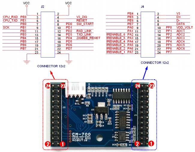
8 Connecting Wireless Communication Module ZIG-110 wireless communication module can be connected to CM-700. Replacing the Fuse There is a fuse to prevent from damaging the circuit due to over current. If the CM-700 does not turn on, there is a high chance your fuse is blown. Replace the fuse right away. The fuse size of CM-700 is as below, and you may use a product with a capacity between 125V / 5A ~ 10A. (It is the same as CM-510) Sub-Board Connector Information The pin layout of the connector which connects CM-700 and SUB board is as below.
9


10 Pin Information to Build User Application Device Power The pin composition of CM-700 power is as below. External 5-Pin Port Users can create a sensor to control and connect to the 5 pin peripheral device connection port. However, composing the wrong circuits may damage your controller s circuit, so please learn more about circuit before doing so. Below is the 5 pin layout information for a peripheral device.

11 1. OUT : 5V Output Possible (Maximum Allowed Current 0.9A) 2. VCC (5V) 3. ADC : The analog signals from the sensor made by the user can be read. 4. GND 5. NC : Not Used Communication Device Connection Port The functions of pins on the communication device connection port are as follows. 1. RXD : Receive Signal Terminal 2. TXD : Transmit Signal Terminal 3. VCC : Supply Voltage ( 2.7~3.6V ) 4. GND : Ground Level (0v) 3-Pin Connector Port The functions of pins on the 3-pin connector port are as follows. Pleaser refer to AX-Series Pin Assignment for more information. Please be careful not to change the direction considering the angular part. 1. GND : Ground Level (0v) 2. VDD : Supply Voltage (It is equal to the voltage of battery) 3. DATA : Data Transmission Pin
12 4-Pin Connector Port The functions of pins on the 4-pin connector port are as follows. Pleaser refer to RX-Series Pin Assignment for more information. (It is compatible with 4-pin of DX and EX Series.) Please be careful not to change the direction considering the angular part. 1. DATA- : Data Transmission Pin 2. DATA+ : Data Transmission Pin 3. VDD : Supply Voltage (It is equal to the voltage of battery) 4. GND : Ground Level (0v) H/W Specification Weight : 37.3g Controller : ATMega2561 Working Voltage o o Allowed Range : 7V ~ 35V Recommended Voltage : Please refer to the above "Power Supply." Consumed Current o When IDLE : 40mA o Exterior I/O Maximum Current : 0.9A o Overall Maximum Current : 10A (Fuse) Working Temperature : -5 ~70 Internal I/O Device
13 o Button : 2 sets (Reset 1, Start 1) o Temperature Sensor : 1 o Voltage Sensor : 1 External I/O Device o OLLO Peripheral-Device Compatible 5 pin I/O Port : 6 o 3-Pin Connector for Dynamixel using TTL Communication : 4 o 4-Pin Connector for Dynamixel using RS-485 Communication : 5 Copyrights (c) 2010 ROBOTIS All rights reserved.
CM-530. Part Photo. Name of Each Part. Show. Home > Product Information > Robot Parts > Controller > CM-530. ROBOTIS e-manual v1.15.
 Show ROBOTIS e-manual v1.15.00 Home > Product Information > Robot Parts > Controller > CM-530 CM-530 Part Photo [CM-530] Name of Each Part [ Name of Each Part : CM-530 ] PC Link (mini USB) : Used to connect
USB2Dynamixel. Part Photo. Product Usage. Name and Usage of Each Part. ROBOTIS e-manual v [USB2Dynamixel]
![USB2Dynamixel. Part Photo. Product Usage. Name and Usage of Each Part. ROBOTIS e-manual v [USB2Dynamixel]](/thumbs/77/75032375.jpg "USB2Dynamixel. Part Photo. Product Usage. Name and Usage of Each Part. ROBOTIS e-manual v [USB2Dynamixel]") ROBOTIS e-manual v1.10.00 USB2Dynamixel Part Photo [USB2Dynamixel] Product Usage USB2Dynamixel is a device used to operate Dynamixel directly from PC. USB2Dynamixel is connected to USB port of PC, and
ROBOTIS e-manual v1.10.00 USB2Dynamixel Part Photo [USB2Dynamixel] Product Usage USB2Dynamixel is a device used to operate Dynamixel directly from PC. USB2Dynamixel is connected to USB port of PC, and
v1.2 Closer to Real, USB2Dynamixel User s Manual ROBOTIS CO.,LTD.
 v1.2 Closer to Real, USB2Dynamixel User s Manual ROBOTIS CO.,LTD. www.robotis.com contents 1. Introduction 2 1-1. Functions 2 1-2. Composition 3 1-3. System Requirements 3 1-4. USB2Dynamixel Connection
User s Manual Closer to Real, Zigbee Module ZIG-100. Wireless Communication. ROBOTIS CO.,LTD
 User s Manual 2006-07-06 Closer to Real, Wireless Communication ROBOTIS CO.,LTD. www.robotis.com +82-2-2168-8787 Contents 1. Page 02 2. Zigbee Setting Page 06 3. PC Interface Zig Board Schematic Page 10
UC-2000 Installation Manual Unicorn Computers Technology Limited
 UC2000 Installation Manual Copyright 2003. All rights reserved. Table of Contents Specifications 2 Enclosure for the UC2000 Controller 3 Unicorn Access Control System Configuration 4 UC2000 Controller
GT- IRDM-9603 Product description Rev. 2 17/06/2014
 GT- IRDM-9603 Product description Rev. 2 17/06/2014 1 1. Overview The GT- IRDM- 9603 is a complete Satellite Terminal solution for Satellite applications. Based on IRIDIUM 9603 module. 2. Hardware Interface
Modtronix Engineering Modular Electronic Solutions SBC28DC. Single board computer for 28 pin DIP PICs
 Modtronix Engineering Modular Electronic Solutions Single board computer for 28 pin DIP PICs Table of Contents 1 Introduction...2 2 Features...4 3 Expansion Connectors...5 3.1 Daughter Board Connectors...5
EZ-Bv4 Datasheet v0.7
 EZ-Bv4 Datasheet v0.7 Table of Contents Introduction... 2 Electrical Characteristics... 3 Regulated and Unregulated Power Pins... 4 Low Battery Warning... 4 Hardware Features Main CPU... 5 Fuse Protection...
Product description Rev. 3 11/06/14
 EZ863-2G - GNSS Product description Rev. 3 11/06/14 1 Table of Contents 1. Overview... 4 2. General Description... 4 2.1 Dimensions... 4 2.2 Weight... 4 2.2 Installation... 5 2.3 Casing material... 6 2.4
Wii Nunchuk Transceiver. Wiring Diagrams
 Wii Nunchuk Transceiver Wiring Diagrams Wii Nunchuk Controller Wiring SCL SCL SDA +3v3 +3v3 Det SDA To Nunchuk Controller Top View Bottom View Bottom View 2.4GHz Wireless Transceiver CMD RXD TXD VCC 220Ω
Supplement for module D041 incl. ATMega8 Prozessor
 Supplement for module D041 incl. ATMega8 Prozessor V 1.4 16. March 2006 2006 by Peter Küsters This document is in copyright protected. It is not permitted to change any part of it. It is not permitted
Supplement for module D061 incl. ATMega128 Prozessor
 Supplement for module D061 incl. ATMega128 Prozessor V 1.3 16. March 2006 2006 by Peter Küsters This document is in copyright protected. It is not permitted to change any part of it. It is not permitted
NM-251D-INC. Dual Axis Inclinometer Output Format converter User Guide V1.00. Introduction
 NM-251D-INC Dual Axis Inclinometer Output Format converter User Guide V1.00 Introduction The NM-251D-INC is a member of the NM- 251 Series family and is programmed to function as an Inclinometer Sensor
Pridgen Vermeer Robotics ATmega128 Revision 0
 Features: 6x 8-bit I/O Ports 4x A/D Inputs 6x PWM Headers 2x RS 232 Terminals Power Bus LCD Header (4-bit mode) Smart Power Connecter Power Switch Header Power LED Debug LED Note: Some pins have multiple
Mercury System SB310
 Mercury System SB310 Ultrasonic Board - Product Datasheet Author Francesco Ficili Date 20/05/2018 Status Released Pag. 1 Revision History Version Date Author Changes 1.0 20/05/2018 Francesco Ficili Initial
EXL x240 Graphic LCD Smart Module 3,8 SHORT FORM TECHNICAL SPECIFICATIONS. Via di Corticella, Bologna, Italy
 320x240 Graphic LCD Smart Module 3,8 SHORT FORM TECHNICAL SPECIFICATIONS www.exelmicroel.it Via di Corticella, 201 40128 - Bologna, Italy Tel: +39 051 6380211 Fax: +39 051 6380226 exelbo@exelmicroel.it
The SC03MPA camera is capable of outputting JPEG format images and PAL/NTSC video (Video is available only per request).
.") SC03MPA: 0.3 Mega Pixels Serial JPEG Camera User Manual 0.3 Mega Pixels Serial JPEG Camera SC03MPA User Manual, Rev. D (2018) For latest user manual, please visit: Introduction The SC03MPA Camera is a
SC03MPA: 0.3 Mega Pixels Serial JPEG Camera User Manual 0.3 Mega Pixels Serial JPEG Camera SC03MPA User Manual, Rev. D (2018) For latest user manual, please visit: Introduction The SC03MPA Camera is a
EZmoto V4.1 Product description Rev. 2 30/07/2015
 EZmoto V4.1 Product description Rev. 2 30/07/2015 1 Contents 1. Overview... 3 2. Hardware Interface Description... 3 2.1 Main features of the EZmoto... 3 2.2 Hardware block diagram... 4 2.3 Internal Hardware
GT- HE910-EUD. Product description Rev. 8 21/02/ Overview
 GT- HE910-EUD Product description Rev. 8 21/02/2013 1. Overview The GT-HE910-EUD is a complete Cellular Terminal solution for GSM/UMTS applications. Based on Telit HE910-EUD module. 1 Hardware Interface
EZ864 UMTS Terminal Telit Cellular GSM Engine
 EZ864 UMTS Terminal Telit Cellular GSM Engine Version: 01.01 EZ864 UMTS Terminal_HD_V01.01 06.Mar.2008-1 - Hardware Interface Description 1. Hardware Features of the EZ864 UMTS Terminal Feature Implementation
SC03MPC: 0.3 Mega Pixels Serial JPEG Camera Infrared User Manual. Introduction
 0.3 Mega Pixels Serial JPEG Camera Infrared SC03MPC User Manual, Rev. C For latest user manual, please visit: Introduction The SC03MPC Camera is a highly integrated serial JPEG camera module which can
NM-251D-DTM. Datum Generator - Data Multiplier User Guide V1.00
 NM-251D-DTM Datum Generator - Data Multiplier User Guide V1.00 Introduction The NM-251D-DTM is a member of the NM-251 Series family and is programmed to produce and output the $GPDTM string in order to
Wiring Section 3-3. NQ-Series communication ports support various types of (serial) communication.
 communication.") 3-3 Wiring NQ-Series models have, besides one power connector, a number of communication ports. Please refer to Table 2.2: Common specifications for NQ-Series and Table 2.3: Specifications per NQ-Series
3-3 Wiring NQ-Series models have, besides one power connector, a number of communication ports. Please refer to Table 2.2: Common specifications for NQ-Series and Table 2.3: Specifications per NQ-Series
Bioloid Premium Kit Turtle Assembly manual v1.0. Bioloid Premium Kit Turtle Assembly Manual
 Bioloid Premium Kit Turtle Assembly manual v.0 Bioloid Premium Kit Turtle Assembly Manual Attention! Before proceeding with assembly you must ensure each actuator s horn is properly aligned. To visually
The Wireless Connectivity Expert
 The Wireless Connectivity Expert 48511 Warm Springs Blvd., Suite 206, Fremont CA 94539 Tel: (510) 490-8024 Fax: (510) 623-7268 Website: http://www.actisys.com/ E-mail: irda-info@actisys.com ACT-IR100SD
0.3 Mega Pixels Serial JPEG Camera with NTSC Video
 SC03MPD: 0.3 Mega Pixels Serial JPEG Camera User Manual 0.3 Mega Pixels Serial JPEG Camera with NTSC Video SC03MPD User Manual, Rev. D For latest user manual, please visit: www.jpegcamera.com Introduction
USR-TCP Hard version: V2.0 File version: V
 Serial Device Server - RS232/RS485 to Ethernet converter USR-TCP232-300 Hard version: V2.0 File version: V1.1 2011-8-17 Serial Device Server - RS232/RS485 to Ethernet converter is an Equipment for convert
1. CP430, CP470, CP474, CP770 and CP774
 1. CP430, CP470, CP474, CP770 and CP774 1.1 Order data CPUs CP430, CP470, CP474, CP770 and CP774 CP430, CP470, CP770 CP474, CP774 Model number 7CP430.60-1 7CP470.60-2 7CP474.60-2 7CP770.60-1 7CP774.60-1
Rover 5. Explorer kit
 Rover 5 Explorer kit The explorer kit provides the perfect interface between your Rover 5 chassis and your micro-controller with all the hardware you need so you can start programming right away. PCB Features:
12-NOV E32 RYN25AI. High performance GPS / Glonass Antenna Module. Datasheet
 12-NOV-2018 56312E32 High performance GPS / Glonass Antenna Module Datasheet PRODUCT DESCRIPTION The REYAX GPS/Glonass receiver module with embedded GPS/Glonass antenna enables high performance navigation
keyestudio Keyestudio MEGA 2560 R3 Board
 Keyestudio MEGA 2560 R3 Board Introduction: Keyestudio Mega 2560 R3 is a microcontroller board based on the ATMEGA2560-16AU, fully compatible with ARDUINO MEGA 2560 REV3. It has 54 digital input/output
RN-174. WiFly GSX Super Module. Features. Description. Applications. rn-174-ds v1.1 3/3/2011
 www.rovingnetworks.com rn-174-ds v1.1 3/3/2011 WiFly GSX Super Module Features Development board containing the RN-171 module, status LEDs, power regulator Supports chip antenna (-C), PCB Trace antenna
RN-174 WiFly Super Module
 RN- WiFly Super Module Features Evaluation board for the RN- module Supports chip antenna (RN--C), PCB trace antenna (RN--P), wire antenna (RN--W), and U.FL connector for an external antenna (RN--U) Ultra-low
07/02 Rev SERVICE MANUAL Service Boards, Page 1 TTK/TEXXTILE. Service Boards
 07/02 Rev. 2.15-01 SERVICE MANUAL Service Boards, Page 1 Service Boards Handling boards... 2 CPU board... 3 Stepper board... 4 Board layout left side... 4 Board layout right side... 5 Board setup... 6
Compact Saia PCD3.M2x30V6 User s Guide
 Compact Saia PCD3.M2x30V6 User s Guide Introduction These CPUs are similar as PCD3.M3230 /.M3330 CPUs except that there is no I/O slots (replaced with a compact I/O Board) and no I/O extension connector.
Energy Management System. Operation and Installation Manual
 Energy Management System Operation and Installation Manual AA Portable Power Corp 825 S 19 TH Street, Richmond, CA 94804 www.batteryspace.com Table of Contents 1 Introduction 3 2. Packing List 5 3. Specifications
BT-22 Product Specification
 BT-22 Product Specification Features Amp ed RF, Inc. Description 10.4 mm x 13.5 mm Our micro-sized Bluetooth module is the smallest form factor available providing a complete RF platform. The BT-22 is
Technical Specification H8922S 3G/4G Router
 www.hongdian.com Technical Specification H8922S 3G/4G Router Contents 1. Product Overview... 2 2. Product Specification... 2 3. Definition of Structure Size and Interface... 3 4. Panel Indicator Status...
PS2 Controller Starter Kit SKPS
 PS2 Controller Starter Kit SKPS User s Manual V1.0 Oct 2008 Information contained in this publication regarding device applications and the like is intended through suggestion only and may be superseded
LATCHING FIBER OPTIC 1xN SWITCHES
 LATCHING FIBER OPTIC 1xN SWITCHES OVERVIEW The fiber optic LATCHING 1xN switches are very fast bidirectional opto-mechanical switches based on the MEMS technology. The component makes an optical connection
 PCE Americas Inc. PCE Instruments UK Ltd. 711 Commerce Way Units 12/13, Southpoint Business Park Suite 8 Ensign Way Jupiter, FL 33458 Hampshire / Southampton USA United Kingdom, SO31 4RF Phone: 561-320-9162
PMS5005 Sensing and Motion Controller User Manual
 PMS5005 Sensing and Motion Controller User Manual Version: 1.0.5 June 2006 Table of Contents I. Introduction 2 I.1. PMS5005 Robot Sensing/Motion Controller Architecture 2 I.2. PMS5005 Connectors and Jumpers
Motorized Capacitor. Electrical Installation of ID Service Bulletin 66
 Plasma Control Technologies Service Bulletin 66 Motorized Capacitor Electrical Installation of ID-5400 Document Information Authors... O. Lehmann / A. Renggli / T. Fenske Document... SB-66-02.doc Created
Product Specification
 Product Specification Features Amp ed RF, Inc. Description 15mm x 27mm The added class 1 power, +18dBm, of the BT-11, gives this module one of the best ranges in the industry. It s completely pin compatible
AQ_G24 GSM Terminal Card Motorola Cellular GSM Engine
 AQ_G24 GSM Terminal Card Motorola Cellular GSM Engine Version: 01.01 AQ_G24 Terminal Card_HD_V01.01 17.JUL.2008-1 - Hardware Interface Description 1. Hardware Features of the AQ_G24 Terminal Card Feature
Motorized Capacitor. Electrical Installation of ID-400. Service Bulletin 63
 Plasma Control Technologies Service Bulletin 63 Motorized Capacitor Electrical Installation of ID-400 Document Information Authors... O. Lehmann / A. Renggli / T. Fenske... W. Bigler / M. Armbruster Document...
IO Expansion Shield User Manual
 IO Expansion Shield User Manual 1 Features 3-pin & 4-pin sensor interfaces, supports connecting sensors directly without complicate custom connections XBee module connector WIFI-LPT100 wireless module
Product description The SWH is a board Cellular Terminal solution for GSM GPS/GLONASS
 SWH Product description The SWH is a board Cellular Terminal solution for GSM GPS/GLONASS Rev.1 01/03/2013 1. Overview The SWH is a complete board Cellular Terminal solution for GSM GPS/GLONASS applications.
Operation Manual of Smart Battery Systems (SBS) with SmBus V1.1 support for 12.8V LiFePO4 battery pack (6.6Ah-100Ah)
 with SmBus V1.1 support for 12.8V LiFePO4 battery pack (6.6Ah-100Ah)") Operation Manual of Smart Battery Systems (SBS) with SmBus V1.1 support for 12.8V LiFePO4 battery pack (6.6Ah-100Ah) AA Portable Power Corp (http://www.batteryspace.com) Address: 860 S, 19 th St, Unit
Operation Manual of Smart Battery Systems (SBS) with SmBus V1.1 support for 12.8V LiFePO4 battery pack (6.6Ah-100Ah) AA Portable Power Corp (http://www.batteryspace.com) Address: 860 S, 19 th St, Unit
BB-303 Manual Baseboard for TMCM-303
 BB-303 Manual Baseboard for TMCM-303 Trinamic Motion Control GmbH & Co. KG Sternstraße 67 D 20357 Hamburg, Germany http://www.trinamic.com BB-303 Manual (V1.04 / Jul 9th, 2007) 2 Contents 1 Features...
MEGATRONICS V3.0 QUICK START GUIDE
 MEGATRONICS V3.0 QUICK START GUIDE Thank you for purchasing the Megatronics v3.0! This small guide will answer the basic questions on how to connect the board to your 3D printer. For more information visit
Multi-IQ. Firmware: RS232-Data Manager for UPS 4 x RS232 / 1 x LAN-Contacts flash upgradeable. User manual. (Serial Number / Seriennummer)
") Version: 2016-08-18 Multi-IQ Firmware: (Serial Number / Seriennummer) RS232-Data Manager for UPS 4 x RS232 / 1 x LAN-Contacts flash upgradeable User manual MANUAL ENGLISH... 2 GENERAL PROPERTIES:... 2
Version: 2016-08-18 Multi-IQ Firmware: (Serial Number / Seriennummer) RS232-Data Manager for UPS 4 x RS232 / 1 x LAN-Contacts flash upgradeable User manual MANUAL ENGLISH... 2 GENERAL PROPERTIES:... 2
Technical User Manual Avisaro 4.0 Product Series
 Technical User Manual Avisaro 4.0 Product Series including PC Companion Software RS232 CAN 4..20mA Analog Version / Date 2019-01-11 1. TABLE OF CONTENT Hint: Use key with mouse click within the
RN-174. WiFly GSX Super Module. Features. Description. Applications. rn-174-ds v1.1 1/24/2011
 www.rovingnetworks.com rn-174-ds v1.1 1/24/2011 WiFly GSX Super Module Features Development board containing the RN-171 module, status LEDs, power regulator Supports chip antenna (-C), PCB Trace antenna
Item Symbol Absolute Maximum Rating Unit Remarks
 7 TFT LCD asi LCD Color Module The is a compact full color TFT LCD module, that is suitable for portable products, industrial products, hand-held products, security products, instrument displays and office
ISP Bluetooth Low Energy Module with Integrated Antenna
 ISP9121 Bluetooth Low Energ Module with Integrated Antenna Ke Features Single Mode Bluetooth Low Energ v4. Slave Based on Nordic Semiconductor famil of ublue products Includes transceiver, baseband and
Note : Power consumption and sample rate will vary according to different firmware versions.
 1.0 Product Page 1 of 5 PenMount 1201A control board is one of the cutting-edge innovations from PenMount. A collectively integrated feature with USB / RS232 interface supporting 5 to 7.9 projected capacitive
Eddie Control Board with Power Connector (#28993) Eddie Control Board PCB (# )
 Eddie Control Board PCB (# )") Web Site: www.parallax.com Forums: forums.parallax.com Sales: sales@parallax.com Technical: support@parallax.com Office: (916) 624-8333 Fax: (916) 624-8003 Sales: (888) 512-1024 Tech Support: (888) 997-8267
Web Site: www.parallax.com Forums: forums.parallax.com Sales: sales@parallax.com Technical: support@parallax.com Office: (916) 624-8333 Fax: (916) 624-8003 Sales: (888) 512-1024 Tech Support: (888) 997-8267
Note : Power consumption and sample rate will vary according to different firmware versions.
 1.0 Product Page 2 of 6 PenMount 1400A control board is one of the cutting-edge innovations from PenMount. A collectively integrated feature with USB / RS232 interface supporting 11.0 to 15.0 projected
DLA. DMX512 Analyzer. DLA Users Manual SV2_00 B.lwp copyright ELM Video Technology, Inc.
 DLA DMX512 Analyzer DLA DLA-HH 1 Table Of Contents IMPORTANT SAFEGUARDS... 2 DLA OVERVIEW... 3 CONNECTION... 3 OPERATION... 3 HARDWARE SETUP... 4 DLA-HH (PORTABLE) LAYOUT... 4 CHASSIS LAYOUT... 4 DLA MENU
NxtG-V Install Manual
 NxtG-V Install Manual 1. Product Overview 1.1. Check Parts List Before starting, check whether all the following items have been included with your NxtG-V. If anything is missing, please contact your supplier.
Bioloid Premium Kit Gerwalk Assembly Manual v1.0. Bioloid Premium Kit Gerwalk Assembly Manual
 Bioloid Premium Kit Gerwalk Assembly Manual v.0 Bioloid Premium Kit Gerwalk Assembly Manual Attention! Before proceeding with assembly, you must ensure each actuator s horn is properly aligned. To visually
3.3V regulator. JA H-bridge. Doc: page 1 of 7
 Digilent Cerebot Board Reference Manual Revision: 11/17/2005 www.digilentinc.com 215 E Main Suite D Pullman, WA 99163 (509) 334 6306 Voice and Fax Overview The Digilent Cerebot Board is a useful tool for
CMS-8GP32. A Motorola MC68HC908GP32 Microcontroller Board. xiom anufacturing
 CMS-8GP32 A Motorola MC68HC908GP32 Microcontroller Board xiom anufacturing 2000 717 Lingco Dr., Suite 209 Richardson, TX 75081 (972) 994-9676 FAX (972) 994-9170 email: Gary@axman.com web: http://www.axman.com
Sanguino TSB. Introduction: Features:
 Sanguino TSB Introduction: Atmega644 is being used as CNC machine driver for a while. In 2012, Kristian Sloth Lauszus from Denmark developed a hardware add-on of Atmega644 for the popular Arduino IDE and
Octagon Systems Corporation, the Octagon logo, the Micro PC log and Micro PC are trademarks of Octagon Systems Corporation.
 5974 PC 104 Card COPYRIGHT Copyright 1993 Octagon Systems Corporation. All rights reserved. However, any part of this document may be reproduced provided that Octagon Systems Corporation is cited as the
Product Specification
 Product Specification 15mm x 27mm Description One of the most capable Bluetooth modules available, the BT-21 Bluetooth OEM Module is designed for maximum flexibility. The BT-21 module includes 14 general
How a 2d barcode scan engine to be integrated with your. I. The imager engine itself with TTL serial interface :
 How a 2d barcode scan engine to be integrated with your Kiosk, POS terminal or others system? By RTscan, June 2014 We have been often asked by our customers about how to integrate the 2d barc ode scan
H3G-48B Production Description
 H3G-48B Production Description Designed for communication battery strings of 24 batteries each of VRLA and Ni-Cd battery 1 Applications For strings of 24 batteries each Base Station (2V X 24 batteries)
SC20MPC: 2 Mega Pixels Serial JPEG Camera User Manual. Introduction
 2 Mega Pixels Serial JPEG Camera SC20MPC User Manual, Rev. F (August 2018) For latest user manual, please visit: Introduction The SC20MPC Camera is a highly integrated serial JPEG camera module which can
ADC7520 SERIES. 1600W Battery Chargers and Power Supplies
 ADC7520 SERIES 1600W Battery Chargers and Power Supplies Wide output adjustment range 0 72VDC Analog control by external 0-5VDC voltage Temp.comp charging, sense as on option Power fail relay alarm Master-Slave
Combining Today s Best Technologies. For Tomorrow s Break Through Discoveries. Feedback Versions Analog Sin/Cos. Control Modes.
 Feedback Versions Analog Sin/Cos Control Modes Command Interface Feedback I/O - Digital Accelnet Micro Panel Dimensions: mm [in]. Model * Vdc Ic Ip ACJ-055-09 20-55 9 ACJ-055-18 20-55 6 18 20-90 1 ACJ-090-09
Serial to Ethernet Converter
 Serial to Ethernet Converter User s Manual Version 1.1 2004 Infosystem Technology Corporation Disclaimers The information in this manual has been carefully checked and is believed to be accurate. Infosystem
ILI2312. ILI2312 Single Chip Capacitive Touch Sensor Controller. Specification ILI TECHNOLOGY CORP. Version: V1.03.
 Single Chip Capacitive Touch Sensor Controller Specification Version: V1.03 Date: 2015/11/17 ILI TECHNOLOGY CORP. 8F, No.38, Taiyuan St., Jhubei City, Hsinchu County 302, Taiwan, R.O.C. Tel.886-3-5600099;
WM1030 Rev Introduction. Ultra low power DASH7 Modem. Applications. Description. 868 / 915 MHz. Features. WIZZILAB Technical datasheet 1/10
 WM1030 Rev. 1.2 Applications Wireless sensor network Data acquisition equipment Security systems Industrial monitor and control Internet of things (IoT) Ultra low power DASH7 Modem 868 / 915 MHz 1 Introduction
Various power connectors. 3.3V regulator. 64K Flash (Internal) 2K EEPROM (Internal) 4K SRAM (Internal) JA Mem Adr/ Data. Doc: page 1 of 9
 2K EEPROM (Internal) 4K SRAM (Internal) JA Mem Adr/ Data. Doc: page 1 of 9") Cerebot II Board Reference Manual Revision: September 14, 2007 Note: This document applies to REV B of the board. www.digilentinc.com 215 E Main Suite D Pullman, WA 99163 (509) 334 6306 Voice and Fax Overview
Cerebot II Board Reference Manual Revision: September 14, 2007 Note: This document applies to REV B of the board. www.digilentinc.com 215 E Main Suite D Pullman, WA 99163 (509) 334 6306 Voice and Fax Overview
RN-174. WiSnap M2 Super Module. Features. Description. Applications. ~ page 1 ~ rn-174-ds v1.1 6/1/2011
 WiSnap M2 Super Module Features Development board containing the RN-171 module, status LEDs, power regulator Supports chip antenna (RN-174-C), PCB Trace antenna (RN-174-P), wire antenna (RN- 174-W) and
EZ864 G. Telit Cellular GSM/UMTS Engine. Hardware guide Version: Update: 27. APR.2009 EZ864 G_Hardware Guide_V
 EZ864 G Telit Cellular GSM/UMTS Engine Hardware guide Version: 04.01 Update: 27. APR.2009 EZ864 G_Hardware Guide_V4. - 1 - Hardware Interface Description 1. Hardware Features of the EZ864 G Feature Implementation
MIDI-Scope. Artistic Licence Engineering Ltd. Software Version V1.3 Manual Revision V1.91
 MIDI-Scope Artistic Licence Engineering Ltd Software Version V1.3 Manual Revision V1.91 Product Registration Form Product: MIDI-Scope Version No. Serial No. Date Purchased: Supplier: Name: Company Name:
ILI2511. ILI2511 Single Chip Capacitive Touch Sensor Controller. Specification ILI TECHNOLOGY CORP. Version: V1.4. Date: 2018/7/5
 Single Chip Capacitive Touch Sensor Controller Specification Version: V1.4 Date: 2018/7/5 ILI TECHNOLOGY CORP. 8F., No.1, Taiyuan 2 nd St., Zhubei City, Hsinchu County 302, Taiwan (R.O.C.) Tel.886-3-5600099;
DIGITAL COMPASS SOLUTION
 Features 5 Heading Accuracy, 0.5 Resolution 2-axis Capability Small Size (19mm x 19mm x 4.5mm), Light Weight Advanced Hard Iron Calibration Routine for Stray Fields and Ferrous Objects 0 to 70 C Operating
LOW VOLTAGE BLDC MOTOR CONTROLLER
 DESCRIPTION The D113-024D10/036D10/050D05 are members of a DSP based low voltage brushless DC motor controller family. The controllers are for controlling the brushless DC motor with or without Hall position
Doc: page 1 of 8
 Minicon Reference Manual Revision: February 9, 2009 Note: This document applies to REV C of the board. 215 E Main Suite D Pullman, WA 99163 (509) 334 6306 Voice and Fax Overview The Minicon board is a
SH1030 Rev Introduction. Ultra low power DASH7 Arduino Shield Modem. Applications. Description. 868 MHz. Features
 SH1030 Rev. 1.2 Applications Wireless sensor network Data acquisition equipment Security systems Industrial monitor and control Internet of things (IoT) Ultra low power DASH7 Arduino Shield Modem 868 MHz
JDY-40 wireless serial port module
 JDY-40 wireless serial port module Brief function introduction JDY-40 is developed by 2.4G technology, with a distance of 120 meters. It uses serial communication interface, which is simple and quick to
Module 3B: Arduino as Power Supply
 Name/NetID: Teammate/NetID: Module 3B: Laboratory Outline As you work on through the labs during the semester and some of the modules you may want to continue experimenting at home. Luckily the microprocessor
SNR610. Embedded network node module SNR610. Description. Feature. Application. SNR610 is highly integrated network module.
 Embedded network node module SNR610 Description SNR610 is highly integrated network module. It adopts high performance Silicon Lab Si4432 RF chip. Si4432 has high reception sensitivity and 100mW output
Power Express. Modular Control System for lighting, drapes and other power circuits control. Introduction System Block Diagram...
 Modular Control System for lighting, drapes and other power circuits control Introduction... 3 1 System Block Diagram...4 2 Control units... 5 2.1 Analog outputs unit, type PEA208...6 2.1.1 Technical specification...6
TBox-Radio & WIRC photocell User manual
 Kit TBox-Radio & WIRC photocells 1. TBox-Radio 1.1 Appearance Radio antenna 2 x Photocells Jack Inputs Ext GPS antenna (TBox-4x only) 4 Group / ID LEDs Radio Config button 2 inputs LEDs Sync Jack RS232
DC3IOB Revision User Guide Updated 3/29/10. Overview
 Revision 080910 User Guide Updated 3/29/10 Overview The is a three axis DC brush motor drive with an integrated PLC. A range of motor drive currents are selectable with jumper blocks. The integrated PLC
WAVETEK BLE-WT51822AA/AB. Revision History. Bluetooth low energy Module WT51822AA (256k) /AB (128k) (Bluetooth Low Energy BT4.0) PRODUCT SPECIFICATION
 /AB (128k) (Bluetooth Low Energy BT4.0) PRODUCT SPECIFICATION") Bluetooth low energy Module WT51822AA (256k) /AB (128k) (Bluetooth Low Energy BT4.0) PRODUCT SPECIFICATION Part number: BLE WT51822AA/AB Wavetek has developed a module which supports Bluetooth Low Energy
Bluetooth low energy Module WT51822AA (256k) /AB (128k) (Bluetooth Low Energy BT4.0) PRODUCT SPECIFICATION Part number: BLE WT51822AA/AB Wavetek has developed a module which supports Bluetooth Low Energy
Evaluation Board for ELM4 / LSM4. Technical Reference Manual
 SWISS PRECISION V 1.4 01.11.2016 To prevent damage by electrostatic discharge (ESD), hold this Evaluation-Board at the edges only. You must be properly grounded before handling this sensitive product.
Mega128-DEVelopment Board Progressive Resources LLC 4105 Vincennes Road Indianapolis, IN (317) (317) FAX
 (317) FAX") Mega128-DEVelopment Board Progressive Resources LLC 4105 Vincennes Road Indianapolis, IN 46268 (317) 471-1577 (317) 471-1580 FAX http://www.prllc.com GENERAL The Mega128-Development board is designed for
Mega128-DEVelopment Board Progressive Resources LLC 4105 Vincennes Road Indianapolis, IN 46268 (317) 471-1577 (317) 471-1580 FAX http://www.prllc.com GENERAL The Mega128-Development board is designed for
USR-TCP Hard version: V1.1 File version: V
 RS232/RS485 to convert module USR-TCP232-24 Hard version: V1.1 File version: V1.2 2011-08-18 RS232/RS485 to convert module is an Equipment for convert TCP or UDP socket data to RS232 or RS485, easy to
RN-171-XV b/g Wireless LAN Module
 RN-171-XV 802.11 b/g Wireless LAN Module Features Drop-in Wi-Fi solution for existing systems that currently use 802.15.4 modules Based on Roving Networks robust RN-171 Wi-Fi module Based on a pseudo-standard
ROBOTIS e-manual v AX-12W. Part Photo [AX-12W] Hardware Specifications. Weight : 52.9g Dimension : 32mm * 50mm * 40mm
![ROBOTIS e-manual v AX-12W. Part Photo [AX-12W] Hardware Specifications. Weight : 52.9g Dimension : 32mm * 50mm * 40mm](/thumbs/82/86399689.jpg "ROBOTIS e-manual v AX-12W. Part Photo [AX-12W] Hardware Specifications. Weight : 52.9g Dimension : 32mm * 50mm * 40mm") ROBOTIS e-manual v1.20.00 AX-12W Part Photo [AX-12W] Hardware Specifications Weight : 52.9g Dimension : 32mm * 50mm * 40mm Resolution : 0.29 Gear Reduction Ratio : 32 : 1 No load speed : 470rpm (at 12V,
ROBOTIS e-manual v1.20.00 AX-12W Part Photo [AX-12W] Hardware Specifications Weight : 52.9g Dimension : 32mm * 50mm * 40mm Resolution : 0.29 Gear Reduction Ratio : 32 : 1 No load speed : 470rpm (at 12V,
Page 1 of 11 Version 1.2 Release Date: PenMount PM2204 PCI Controller Board Data Sheet. Table of contents
 Page 1 of 11 Table of contents Table of contents... 1 Revision history... 2 1.0 Introduction... 3 2.0 Specifications... 4 3.0 Mechanical drawing... 5 3.1 Mechanical size... 5 3.2 Touch line pin definition...
Wireless Sensor Networks. FireFly 2.2 Datasheet
 2.2 Datasheet July 6, 2010 This page intentionally left blank. Contents 1. INTRODUCTION...1 Features...1 Applications...2 2. BLOCK DIAGRAM...3 3. HARDWARE CONNECTIONS...4 Power...5 Header 1 ( UARTS, I2C,
BLE MODULE SPECIFICATIONS
 WIRELESS-TAG BLE MODULE SPECIFICATIONS nrf51-01/02/dk Bluetooth Low Energy (BLE) module of nrf51-01/02 is the next generation BLE module released by SEMITRION electronics. The modules use nrf51822 from
ARDUINO PRIMO. Code: A000135
 ARDUINO PRIMO Code: A000135 Primo combines the processing power from the Nordic nrf52 processor, an Espressif ESP8266 for WiFi, as well as several onboard sensors and a battery charger. The nrf52 includes