Institutionen för datavetenskap Department of Computer and Information Science
|
|
|
- Terence Miller
- 5 years ago
- Views:
Transcription
1 Institutionen för datavetenskap Department of Computer and Information Science Master Thesis Integration of OpenModelica into the Multi-paradigm Modeling Environment of Ptolemy II by Mana Mirzaei LIU-IDA/LITH-EX-A--13/065--SE Linköpings universitet SE Linköping, Sweden Linköpings universitet Linköping 1
2 Examensarbete Integration av OpenModelica med Multi-Paradigm Modelleringsramverket Ptolemy II av Mana Mirzaei LIU-IDA/ LITH-EX-A--13/065--SE Handledare: Dr. Lena Buffoni Examinator: Prof. Peter Fritzson
3
4 Contents Chapter 1 Introduction Background Purpose Thesis Overview... 8 Chapter 2 Background Modelica OpenModelica Ptolemy II Chapter 3 OpenModelica in Ptolemy II Motivation Drawbacks and Problems Today Approach Chapter 4 OpenModelica Extension The Software Architecture of OpenModelica to Create New Extension of Ptolemy II Interactive Simulation of the Modelica Models Non-Interactive Simulation of the Modelica Models The Software Architecture of Ptolemy II to Create New Extension of OpenModelica OpenModelica Director OpenModelica Actor OpenModelica Execution in Ptolemy II Chapter 5 Implementation Graphical User Interface Code structure Implementation Challenges Incomplete OpenModelica API Time Challenge Chapter 6 Testing System Testing in Ptolemy II Test Cases Performance Chapter 7 Conclusion Future Works Improve Ptolemy II by Adding OpenModelica Import Menu Design New Library Known as BCVTB for OpenModelica Library Appendix A User Guide Getting Started Installation Model Examples Example 1 Simple Model for Plotting PLT File Example 2 - Composite Model for Plotting CSV File by XYPlotter Example 3 Composite Model for Displaying the Result of Simulation in Interactive Processing Mode Example 4 Composite Model for Modifying Parameter of the Super Model Bibliography Table of Acronyms... 60
5 Table of Figures FIGURE 1. CLIENT-SERVER INTERCONNECTION STRUCTURE OF THE COMPILER/INTERPRETER MAIN PROGRAM AND INTERACTIVE TOOL INTERFACES FIGURE 2. CLIENT-SERVER INTERCONNECTION STRUCTURE OF THE COMPILER/INTERPRETER MAIN PROGRAM AND INTERACTIVE TOOL INTERFACES AFTER ADDING NEW PTOLEMY II AS A NEW CLIENT FIGURE 3. OMI COMMUNICATION ARCHITECTURE TABLE 1. OMI SERVER AND CLIENT COMPONENTS TABLE 2. PTOLEMY II SERVER AND CLIENT COMPONENTS FIGURE 4. KEY PACKAGES AND COMPOSING CLASSES IN PTOLEMY II FIGURE 5. OPENMODELICA DIRECTOR WITH ITS PARAMETERS FIGURE 6. DOMAIN PACKAGE IN PTOLEMY II FIGURE 7. DOMAIN PACKAGE AFTER ADDING OPENMODELICA DOMAIN FIGURE 8. FLOW OF THE CONTROL OF PTOLEMY II S COMPOSITE ACTOR FIGURE 9. OPENMODELICA ACTOR WITH ITS SAMPLE PARAMETERS FIGURE 10. INTERACTION DIAGRAM BETWEEN PTOLEMY II AND OPENMODELICA FIGURE 11. OPENMODELICA.XML FIGURE 12. OPENMODELICA DIRECTOR IN EXPERIMENTALDIRECTORS.XML FIGURE 13. OPENMODELICA SUB-PACKAGES FIGURE 14. CLASS DIAGRAM OF THE LIB PACKAGE FIGURE 15. PART OF THE CONSTRUCTOR OF OPENMODELICA CLASS FIGURE 17. CODE SNIPPET OF OMITHREAD CLASS FIGURE 18. THE CODE SNIPPET SHOWS THE IMPLEMENTATION OF FIRE() METHOD ONE OF THE KEY FUNCTIONS OF OPENMODELICA ACTOR FIGURE 19. FUNCTIONS INCLUDED IN THE FIRE METHOD OF OPENMODELICA ACTOR FIGURE 20. FUNCTION WHICH IS INVOKED IN WRAPUP METHOD TABLE 3. NUMBER OF LINES IN JAVA CLASSES TABLE 5. TEST CASE S TABLE 6. TEST CASE S TABLE 7. TEST CASE S TABLE 4. EXECUTION TIME OF TEST MODELS IN PTOLEMY II AND OPENMODELICA FIGURE 21. OPENMODELICAPLTPLOT.XML FIGURE 22. PARAMETERS OF OPENMODELICA IN OPENMODELICAPLTPLOT.XML FIGURE 23. PARAMETERS OF DCMOTOR FIGURE 24. PLOTTING OPENMODELICA SIMULATION BY PLTPLOTTER FIGURE 25. OPENMODELICAXYPLOTTER.XML AND THE CONTAINED MODEL FIGURE 26. PARAMETERS OF OPENMODELICA IN OPENMODELICAXYPLOTTER.XML FIGURE 27. PLOTTING OPENMODELICA SIMULATION BY XYPLOTTER AND DISPLAYING BY DISPLAY ACTOR FIGURE 28. FLOW OF CONTROL FOR RUNCOMPOSITEACTOR IN OPENMODELICAXYPLOTTER.XML 51 FIGURE 29. OPENMODELICAINTERACTIVE.XML WITH THE CONTAINED MODEL FIGURE 30. PARAMETERS OF OPENMODELICA ACTOR IN OPENMODELICAINTERACTIVE.XML FIGURE 31. PARAMETERS OF RAMP ACTOR IN OPENMODELICAINTERACTIVE.XML FIGURE 32. DISPLAYING PART OF SIMULATION RESULT OF OPENMODELICAINTERACTIVE.XML BY DISPLAY ACTOR FIGURE 33. OPENMODELICAINHERIT.XML WITH THE CONTAINED MODEL FIGURE 34. SET PARAMETER OF OPENMODELICA ACTOR WITH PART OF THE CSV GENERATED FILE IN NON-INTERACTIVE PROCESSING FIGURE 35. SET PARAMETER OF OPENMODELICA ACTOR WITH PART OF THE SIMULATION RESULT IN INTERACTIVE PROCESSING... 57
6 Acknowledgments I would like to express my gratitude towards the people who helped me through this thesis, without them this project would not have been made possible. First of all, I would like to thank Christopher Brooks, Software Manager of the Ptolemy Project and Adeel Asghar, OpenModelica developer for offering significant support throughout the thesis work. Furthermore, I would like to express my appreciation to my supervisor Dr. Lena Buffoni and examiner Professor Peter Fritzson for providing great inspiration during this thesis work. Linköping, 2014 Mana Mirzaei
7 Chapter 1 Introduction This chapter is the introduction of a thesis work that completes my studies in Master of Science at Linköping University. The thesis work has been performed at the Programming Environment Laboratory (PELAB) in IDA in collaboration with the Center for Hybrid and Embedded Software Systems (CHESS) in the Department of Electrical Engineering and Computer Sciences of the University of California at Berkeley. 1.1 Background Concurrent systems are becoming increasingly common in spite of their complexity. Therefore, a multitude of computational models and tools for modeling and developing such systems have emerged. Ptolemy II is an environment for modeling, simulation and design of large concurrent real-time systems [2] which is mainly centered on addressing heterogeneous systems. Ptolemy II which is developed at CHESS in the Department of Electrical Engineering and Computer Sciences of the University of California, is a system-level design environment that provides the possibility of blending different versions of Models of Computation (MoCs) in one hierarchical heterogeneous model [3]. Modelica [6] is a non-proprietary, objectoriented, equation based language aimed at modeling complex multi-domain physical systems. This language is also supported by a number of free and commercial tools, in particular by OpenModelica [4], an open source compiler and tool suite. 1.2 Purpose This thesis work concerns the integration of OpenModelica into the multi-paradigm environment of Ptolemy II. The integration of OpenModelica and Ptolemy II allows the simulation of non-causal models in Modelica by the OpenModelica Compiler and simulator within the Ptolemy II environment where models communicate with different versions of MoCs with the aim of addressing the heterogeneous design as well.
8 1.3 Thesis Overview This section explains how the report is constructed and gives a brief description of the content of each chapter. The purpose of this section is providing a quick overview for the reader: Chapter 2: its only purpose is giving a short background about Modelica, OpenModelica and Ptolemy II. Chapter 3: provides the motivation for this thesis work, the current drawbacks and the overview of the proposed solution. Chapter 4: provides the implementation process of OpenModelica extension. Chapter 5: provides the code structure of the implementation, challenges during the implementation and brief comparison between the performance of running two test models in Ptolemy II and OpenModelica. Chapter 6: investigates two testing approaches in Ptolemy II, examines the selected one for the integration and illustrates three test cases with their snapshots. Chapter 7: Provides the conclusion and future suggestions on the development of collaborative project of OpenModelica and Ptolemy II.
9 Chapter 2 Background 2.1 Modelica According to [Peter Fritzson. Principles of Object-Oriented Modeling and Simulation with Modelica 2.1, Wiley-IEEE Press, 2004.], Modelica is a modeling language that allows specification of mathematical models of complex natural or man-made systems. The arrival of the Modelica modeling language brings a revolution in modeling and simulation based on the ability to create model libraries with re-usable components and on supporting modeling and simulation of multi-domain applications [7]. The Design of the Modelica language provides the opportunity of generating efficient simulation code automatically with the aim of facilitating exchange of models, model libraries and simulation specifications by tools. In terms of software component modeling, Modelica is based on a powerful model that provides the opportunity of creating and connecting components. The Modelica language realizes a connection mechanism among components, components are instances of the Modelica classes and connectors are interfaces of components [7]. Moreover, connections impose equation constraints on variables. 2.2 OpenModelica There has been an enormous evolution in the specification of Modelica over the past 13 years. The Modelica user community has grown to become fairly large, a number of commercial tools are available implementing the Modelica language such as Dymola [15] and MathModelica [8]. Additionally, an open-source tool, OpenModelica, an open-source environment with the purpose of modeling and simulation of Modelica models [4] is under development since September 1997 [10]. The effort for developing OpenModelica is supported and coordinated by the Open Source Modelica Consortium (OSMC). The first major computational and simulation goal of OpenModelica effort is providing an interactive computational environment for the Modelica language in order to make the Modelica language widely available for the development and execution of algorithms for controlling system design, solving nonlinear equation systems, or developing optimization algorithms that are applied to complex applications [6].
10 The other goal is providing an environment for having a rather complete implementation of the Modelica language that entails the simulation of equationbased models and additional facilities in the programming environment [6]. 2.3 Ptolemy II The Ptolemy Project 1 started working on developing Ptolemy II in Indeed the key goals of developing Ptolemy II were: utilizing the capabilities of Java, network integration, code migration and built-in threading as well as centering on the mechanism of combining actors with multi-paradigm modeling [1]. Ptolemy II also proposed the concept of domain polymorphism 2 and modal models 3 [13]. Some of the fundamental Ptolemy II features are as follows [14]: Java, Ptolemy II is implemented in Java, which allows Ptolemy II to be: Platform independent, currently Ptolemy II runs under Solaris and Windows. Threaded, Ptolemy II builds on the threading primitives in Java. Modularity, Ptolemy II is composed of software packages that can be utilized independently. Mutable System, Ptolemy II allows the design to be modified as it is running. Software Architecture, Ptolemy II has designed with object modeling and design patterns in mind A component can be created to run on various MoCs. 3 Hierarchical combination of finite state machines with other MoC's.
11 Chapter 3 OpenModelica in Ptolemy II This chapter explains the reason that Modelica is of significant interest in Ptolemy II and investigates the existing approach for simulation of the Modelica models within the Ptolemy II environment. Afterwards, I provide a brief description of the integration mechanism to improve the previous approach. 3.1 Motivation In Modelica, components are concurrent and communicate via ports, these ports are considered neither inputs nor outputs and the connections between ports impose equation constraints on variables that all lead to actor-like semantics of Modelica. Modelica is actually most suited to modeling physical systems, that can be intuitively described by equations. Ptolemy II project mainly addresses the heterogeneous modeling, simulation and design of concurrent embedded systems. The major motivation of this project is generating models that can be implemented in a broad variety of computational models such as discrete-event, continuous-time, finite-state machine, synchronous data-flow and etc. Therefore, the use of the Modelica models in the causal environment of Ptolemy II allows the simulation of the non-causal models of Modelica in combination with variant Models of computation that are realized in Ptolemy II, such as synchronous data-flow to support the design of heterogeneous systems. 3.2 Drawbacks and Problems Today In the approach of simulating the Modelica model in Ptolemy II through Dymola [15], the Ptolemy-based co-simulation tool known as Building Controls Virtual Test Bed (BCVTB 4 ) is employed for conducting the co-simulation. This approach causes the constraint of adding the BCVTB block to the Modelica model in order to enable simulation in Ptolemy II. 4
12 The core purposes of BCVTB are co-simulation, real-time simulation and run-time coupling of different simulation programs for data exchange. Through co-simulation at least two simulators, each solving an initial-value differential or difference equation, are coupled to exchange dependent data on the state variables. Moreover, BCVTB couples any number of simulation programs, in place of coupling two simulators directly. The software architecture of BCVTB is a modular design which provides the graphical model building environment, synchronizes the exchanged data and visualizes the system evolution during run-time [16]. In that approach, Ptolemy II acts as the middleware for implementing BCVTB and actors in Ptolemy II are responsible for starting a server that uses the BSD 5 socket utilized for exchanging data between the simulator and the actor as well as implementing the inter-process communication [16]. 3.3 Approach Prior to this thesis work, the simulation of the Modelica model in Ptolemy II were not available. An initial batch-oriented version of simulating Modelica models in Ptolemy II was added early. During the course of this work, the possibility to simulate Modelica models from Ptolemy II using the proprietary Dymola tool was added, requiring an additional library called BCVTB. In our approach, OpenModelica, an open source tool for modeling and simulation of the Modelica models, has been added as a new Model of Computation to Ptolemy II s domains. OpenModelica is quickly growing to be a successful alternative to commercial simulation and mathematical packages such as Mathworks Simulink. OpenModelica makes the model-building easier through employing model/sub-model relationships to improve model reusability. The creators of Ptolemy II follow an analogous set of rules to OpenModelica through using an OOP 6 -like architecture in order to build and improve models [23]. Adding this new MoC domain enables the simulation of the Modelica models via OMC within the Ptolemy II environment to communicate with other Models of Computation to address the heterogeneity of the design. Moreover, our approach removes the need for including the additional library of BCVTB block in the Modelica models that are supposed to be simulated. 5 Berkeley Software Distribution 6 Object Oriented Programming
13 Chapter 4 OpenModelica Extension In the first part of the integration process, it is essential to inspect the software architecture of OpenModelica and Ptolemy II with the goal of figuring out the starting point of creating new extension in Ptolemy II. In this work, the course of the integration was divided into two primary steps: 1. Investigation of the software architecture of OpenModelica to figure out how the integration to Ptolemy II should be carried out. 2. Investigation of the software architecture of Ptolemy II to figure out how an OpenModelica director should be added as a new software extension. Then, the execution sequence of OpenModelica in Ptolemy II is explained and the overall interaction between OpenModelica and Ptolemy II is depicted with an interaction diagram.
14 4.1 The Software Architecture of OpenModelica to Create New Extension of Ptolemy II First the software architecture of OpenModelica was inspected to figure out how the integration to Ptolemy II should be carried out. The OpenModelica architecture is client-server structure, as illustrated in Figure 1. Figure 1. Client-Server interconnection structure of the compiler/interpreter main program and interactive tool interfaces. Components of OpenModelica including the compiler/interpreter main program act as a server which serves interactive tool interfaces such as Graphic Model Editor, Interactive Session Handler and Eclipse Plugin via CORBA 7 standard. The server component that is mainly involved in this integration is the OpenModelica Compiler (OMC). OMC is invoked via CORBA from the client side and Ptolemy II acts as a new client beside other interactive tool interfaces as illustrated in the new Client-Server architecture of OpenModelica in Figure 2. 7 Common Object Request Broker Architecture is a standard defined by Object Management Group (OMG),
15 Figure 2. Client-Server interconnection structure of the compiler/interpreter main program and interactive tool interfaces after adding new Ptolemy II as a new client. Following the invocation of the server from Ptolemy II, the generated output from OMC is retrieved as an executable simulation application. This application provides both an interactive and non-interactive simulation runtime Interactive Simulation of the Modelica Models OpenModelica also offers an on-line user-interactive and time synchronous simulation mode. This simulation with user interactivity is known as OpenModelica Interactive (OMI), is part of the simulation runtime core. OMI provides an executable simulation application, running the executable file in an interactive processing mode enabling users to govern the simulation runtime behavior [11].
16 OMI is composed of two modules, Control and Transfer which are designated for communication over TCP/IP 8 as demonstrated in Figure 2. Figure 3. OMI communication architecture. First, an overview of the interaction mechanism of the Control and Transfer modules is given, then the network configuration on both the client and server sides is described to elaborate the communication between Ptolemy II and OMI. Control module is the interface between OMI and Ptolemy II which is implemented as a single thread to support parallel tasks and independent reactivity. The Control module is considered as the major controlling and communication instance at the simulation initialization phase as well as managing simulation properties throughout the simulation runtime. The control module also reacts to the feedback from other internal OMI components and sends some messages back to Ptolemy II including error and status messages. Transfer module gets simulation results from a result manager and sends them to Ptolemy II upon launching a simulation. Additionally, the module employs filter mask property containing names of all properties whose result values are significant to Ptolemy II. 8 Internet protocol suite : Transmission Control Protocol/Internet Protocol
17 According to the description of the modules composing OMI, some components for running these modules should be designed in both Ptolemy II as a client and OMI as a server. On the server side, OMI, two components for running the Control modules and one for running the Transfer module are designed by OpenModelica developers as configured in Table 1. Some components should be designed on the client side, Ptolemy II, to be served by the server side components, respectively. Thus, I designed the client side components including two components for running the Control modules and one for running the Transfer module as configured in Table 2. These components are implemented as Java classes in Ptolemy II. Table 1. OMI server and client components. Name Description URL Control Server Control Client Transfer Client Waits for requests from the UI Replies to the UI and sends out other synchronization messages Sends simulation results to a UI By Default, waits for connection on: :10501 By Default, waits for connection on: :10501 By Default, tries to connect on: :10502 Table 2. Ptolemy II server and client components. Name Description URL Control Client Control Server Transfer Server Requests to the OMI Control Server Waits for information from the OMI Control Client Waits for simulation results from the OMI Transfer Client By Default, tries to connect on: :10501 By Default, waits for connection on: :10500 By Default, waits for connection on: :10502 As a result of running the key modules and the interaction between them on both the client and the server sides, the simulation result is retrieved in string format from the server and used by the specific components of the Ptolemy II client Non-Interactive Simulation of the Modelica Models The executable simulation application which is generated by OMC can also be run using the non-interactive simulation runtime, the batch mode. In contrast to the Interactive Simulation mode of OMC, the batch mode does not offer any userinteractive simulation and it is not possible to have the result back to the client step by step. Running the executable file in batch processing mode results in generating the whole simulation result in MAT, CSV 9 or PLT 10 file formats. The latter two formats can be utilized through the specific components of the Ptolemy II client. 9 Comma-Separated Values
18 4.2 The Software Architecture of Ptolemy II to Create New Extension of OpenModelica At the beginning of the work, I inspected the carefully designed package structure of Ptolemy II to create custom software extensions to OpenModelica, including some of the key packages and consisting of the Java classes shown in Figure 4 [ 1]. Figure 4. Key packages and composing classes in Ptolemy II. The actor package shown in Figure 4 includes the principal classes defining the execution process of a model which is the key package that should be inspected to have the OpenModelica extension. For implementing this extension, I created one custom actor and one director. In the first place, it is essential to investigate the Director class in the actor package to figure out how new director can be added to Ptolemy II OpenModelica Director Directors in Ptolemy II implement Models of Computation (MoC) to define the semantics of a computational model. An MoC is considered to be a collection of rules which govern concurrent execution of the components and the communication between them. As was mentioned earlier in the background chapter, the major emphasis in Ptolemy II is on the heterogeneous combination of MoCs, there are different types of MoCs in Ptolemy II including Continuous time, Discrete time, Process Network, Synchronous Data-Flow and etc. [7]. 10 Structured on the basis of a set of commands embedded in the ROM of pen plotters that lower the workload for applications programmers for creating plotter output [ 22].
19 A suitable MoC should be selected prior to adding a new director. In this integration, the one which is most relevant to the Modelica language should be considered. Some of the Models of Computation in Ptolemy II strongly depend on time such as Discrete-Event and Continuous-Time models, which actors communicate and perform computation based on a logical time line. Continuous-time models are realized using the Ptolemy II continuous-time (CT) domain which models physical processes. The continuous domain supports mixtures of discrete and continuous behaviors. Such combinations are suitable for many cyberphysical systems. Cyber-physical systems are characterized by a mixture of computational and physical processes. Additionally, the continuous dynamics of physical processes are typically represented using Ordinary Differential Equations (ODEs). One of the fundamental concepts of the Modelica language is the evolution of a continuous-time model continuously due to being composed of variables described using Differential-Algebraic Equations (DAEs). As the Modelica language designed for continuous and discrete-event modeling of physical systems and variables described using DAEs, continuous-time domain in Ptolemy II which models physical processes and supports mixtures of discrete and continuous behaviors is considered more suitable for the Modelica language. Thus, OpenModelica director is implemented based on the continuous-time director. The OpenModelica director with all its parameters in the Graphical User Interface of Ptolemy II known as Vergil, is displayed in Figure 5.


20 Figure 5. OpenModelica director with its parameters. Each MoC has its own package which requires the design of a new package for the OpenModelica domain. I added the new package of OpenModelica domain to one of the key packages of Ptolemy II called domain, shown in Figure 6. Domain package in Ptolemy II provides domains which implement a MoC, and some of them include their own domain-specific actor libraries.
21 Figure 6. Domain package in Ptolemy II. The package displayed in Figure 6 does not include all the domains and the experimental ones, it is only restricted to the leading ones. As it is shown in Figure 7, I added the OpenModelica domain as a new package to the current domain package of Ptolemy II.
22 Figure 7. Domain package after adding OpenModelica domain.

23 The following step is adding the other component which is essential for completing this thesis work, an actor which is known as OpenModelica. The Java class of the OpenModelica actor is implemented in the lib package OpenModelica Actor Many models in Ptolemy II are actor-oriented models which are based on connected groups of actors. Viewing a system as a structure of actors emphasizes its causal structure and its concurrent activities, along with their communication and data dependencies [1]. The connections between actors represent variant types of interaction between components in a design, such as the asynchronous message, rendezvous communication, discrete, continuous ones, etc. The model which supports the actor-oriented design is composed of actors. Actors, the basic building block of a system, are the executable entities which considered the core notion in this structure. There are two types of actors in terms of the use of hierarchy: composite and atomic actor. There are two types of composite actors, opaque and transparent ones. An opaque actor consists of various computation models within an individual model with a director which is helpful for having a hierarchical heterogeneity. However, the transparent one cannot be executed alone. Atomic actors are not considered as a Ptolemy II model itself and they should be included in other models to get executed. In terms of the flow of control in Ptolemy II, when a composite actor is fired, the director inside the composite actor fires the actors of the contained model. In the model, the top-level composite actor contains a director D1, and A2 is a hierarchical composite actor with director D2. Hence, director D1 controls the execution order of actors A1 and A2, and director D2 controls the execution of A3 and A4 whenever A2 is executed as depicted in Figure 22. Figure 8. Flow of the control of Ptolemy II s composite actor. In addition to the mechanism for categorizing actors in terms of the hierarchy, actors can also fall in two other categories, domain specific or domain polymorphic actor. Domain polymorphic actors operate under the control of multiple domains which leads to improving the reusability of actors and reducing the code duplication. However, domains specific ones works solely under the control of one specific director.

24 I designed the OpenModelica actor as a non-composite one which only works under the control of the OpenModelica director. The OpenModelica actor with all its parameters in Vergil is displayed in Figure 5. Figure 9. OpenModelica actor with its sample parameters.
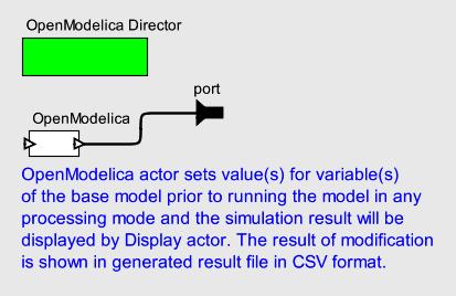
25 4.3 OpenModelica Execution in Ptolemy II An execution in Ptolemy II falls into three phases: setup, iterate, and wrapup. The setup phase is divided into two phases, preinitialize and initialize. The preinitialize sub-phase usually handles structural information, such as constructing dynamically created actors, determining the width of ports, and creating receivers. The initializate phase initializes parameters, resets local state, and produces initial tokens. The preinitialize phase of an actor is performed exactly once during the actor s life of execution, and before any other execution of the actor. The initialization of an actor is performed once after the preinitialize and type resolution. To organize the iterations among actors, an iteration is divided into prefire, fire, and postfire. Prefire checks if the preconditions are fulfilled for the actor to execute, such as the presence of sufficient inputs to complete the iteration. Most of the actions take place during the fire phase, which involves reading inputs, processing data, and producing outputs. MoCs like synchronous reactive models and Continuous Differential Equations compute the fixed point of actor outputs while keeping the state of each actor constant. Thus, when fixed point is reached, the state of an actor is updated which requires the firing of each actor several times before the actor is postfired. Finally, at the end of the execution, wrapup phase taken place exactly once and actors release resources that were allocated during execution [24]. Some MoCs like synchronous reactive models and CT differential equations support fixed-point iteration which enables the computation of the fixed point of actor outputs while keeping the state of each actor constant. Invocation of fire() several times prior to the invocation of postfire() results to updating the state of an actor at the time of reaching the fixed point. However, in this integration, when postfire() is invoked in the OpenModelicaDirector, it returns false in order to stop the invocation of fire() after firing once. To sum up the execution of OpenModelica in Ptolemy II, in the first place, the OpenModelica actor starts the OpenModelica Compiler(OMC) server in the initialize() method, by invoking initializeserver(). In the fire(), value(s) of the Modelica parameter(s) are modified by Ptolemy IIs' actor(s) prior to the simulation of the Modelica model through OMC. After simulation of the Modelica model, the retrieved result back from OMC server is plotted/displayed through Ptolemy IIs' actors. Afterwards, the OpenModelica actor sends the result to the output port which enables using the generated result by other Ptolemy IIs' actors. All these actions are done in fire(). In the final step, OMC is stopped by sending the quit command to the server. All these steps are shown in Figure 10. The functionality of all these methods are elaborated in the following Chapter.
26 Figure 10. Interaction diagram between Ptolemy II and OpenModelica.
27 Chapter 5 Implementation This chapter provides brief information about how OpenModelica components are added to Ptolemy II, the code structure of the implementation and challenges during the implementation. 5.1 Graphical User Interface For designing the OpenModelica actor, I followed the approach that is already implemented for other actors. For each actor, one file in the Modeling Markup Language (MoML) format should be created in one of the sub-packages of OpenModelica, known as a lib which embraces the domain-specific actors. This package will be described together with all its constituent classes in Section 5.2. The MoML format is one of the primary mechanism for designing models which are executed over the network and the persistent file format for Ptolemy II models [14]. The MoML file for OpenModelica actor is illustrated in Figure below. <?xml version="1.0" standalone="no"?> <!DOCTYPE entity PUBLIC "-//UC Berkeley//DTD MoML 1//EN" " <entity name="openmodelica" class="ptolemy.moml.entitylibrary"> <configure> <?moml <group> <doc>openmodelica Actor(s)</doc> <entity name="openmodelica" class="ptolemy.domains.openmodelica.lib.openmodelica"> <property name="_icon" class="ptolemy.vergil.icon.boxedvalueicon"> <property name="attributename" value="expression"/> <property name="displaywidth" value="60"/> </property> </entity> </group>?> </configure> </entity> Figure 11. OpenModelica.xml In Ptolemy II, new directors like OpenModelica are added as experimental directors. There is a MoML file for experimental directors as shown in Figure 12 and
28 OpenModelicaDirector which is added as a new property with the proper location is highlighted. <?xml version="1.0" standalone="no"?> <!DOCTYPE plot PUBLIC "-//UC Berkeley//DTD MoML 1//EN" " <entity name="experimentaldirectors" class="ptolemy.moml.entitylibrary"> <configure> <?moml <group> <doc>experimental director library</doc> <property name="ca Director" class="ptolemy.domains.ca.kernel.cadirector"/> <property name="ci Director" class="ptolemy.domains.ci.kernel.cidirector"/> <property name="do Nothing Director" class="ptolemy.actor.donothingdirector"/> <property name="dt Director" class="ptolemy.domains.dt.kernel.dtdirector"/> <!-- HDE is not shipping in > <!-- property name="hde Director" class="ptolemy.domains.hde.kernel.hdedirector"/--> <property name="giotto Director" class="ptolemy.domains.giotto.kernel.giottodirector"/> <!-- Don't include hs domain --> <!-- property name="hs Director" class="ptolemy.domains.hs.kernel.hsmixedsignaldirector" /--> <!-- property name="hs Embedded Director" class="ptolemy.domains.hs.kernel.hsembeddeddirector" /--> <property name="openmodelica Director" class="ptolemy.domains.openmodelica.kernel.openmodelicadirector"/> <!-- If you remove TimedPNDirector, then please update the pn chapter --> <property name="timed PN Director" class="ptolemy.domains.pn.kernel.timedpndirector"/> <property name="tm Director" class="ptolemy.domains.tm.kernel.tmdirector"/> <property name="psdf_director" class="ptolemy.domains.psdf.kernel.psdfdirector"/> <property name="petrinet Director" class="ptolemy.domains.petrinet.kernel.petrinetdirector"/> <!-- Don't include RTP --> <property name="dde Director" class="ptolemy.domains.dde.kernel.ddedirector"/> <!-- FairDF is not shipping in > <!--property name="fairdf Director" class="ptolemy.domains.fairdf.kernel.fairdfdirector"/--> <!--property name="distributed SDF Director" class="ptolemy.distributed.domains.sdf.kernel.distributedsdfdirector"/--> <property name="pthales Director" class="ptolemy.domains.pthales.kernel.pthalesdirector"/> </group>?> </configure> </entity> Figure 12. OpenModelica Director in experimentaldirectors.xml.

29 5.2 Code structure As shown in Figure 6 in 4.2.1, domain packages in Ptolemy II are composed of three sub-packages, thus I followed the same rule for creating the OpenModelica package as depicted in Figure 13. The kernel one contains the classes that extend those in the actor or kernel packages of Ptolemy II, the lib package encompasses domain-specific actors and the key classes that are necessary for running the integration. And finally, the demo package which contains the sample Modelica models that are supposed to be built by OMC such as dcmotor.mo and BouncingBall.mo. In addition to the Modelica models, the key members of demo are individual demonstration files in MoML format. Figure 13. OpenModelica sub-packages. The class diagram of lib package which includes the key classes of this integration is depicted below:

30 Figure 14. Class diagram of the lib package. All actor classes in Ptolemy II are written in Java and located in the lib package of the domain. The class that I implemented in Java for the OpenModelica actor is OpenModelica.java. The constructor of the OpenModelica actor containsembraces the definition of input/output ports and other parameters of the actor, such as simulationstarttime, processingmode and output port, as highlighted in the below code snippet. public OpenModelica(CompositeEntity container, String name) throws NameDuplicationException, IllegalActionException { super(container, name); input = new TypedIOPort(this, "input", true, false); input.setmultiport(true); output = new TypedIOPort(this, "output", false, true); output.setmultiport(true); filename = new FileParameter(this, "filename"); filename.setdisplayname("file name"); processingmode = new StringParameter(this, "processingmode"); processingmode.setdisplayname("select the processing mode "); processingmode.setexpression("non-interactive"); processingmode.addchoice("non-interactive"); processingmode.addchoice("interactive"); submodel = new StringParameter(this, "submodel");
31 submodel.setdisplayname("model name"); basemodel = new StringParameter(this, "basemodel"); basemodel.setdisplayname("inherits from "); simulationstarttime = new Parameter(this, "simulationstarttime", new DoubleToken(0.0)); simulationstarttime.settypeequals(basetype.double); simulationstarttime.setdisplayname("simulation start time"); simulationstoptime = new Parameter(this, "simulationstoptime", new DoubleToken(0.1)); simulationstoptime.settypeequals(basetype.double); simulationstoptime.setdisplayname("simulation stop time"); } Figure 15. Part of the constructor of OpenModelica class. As it is shown in Figure 14, the OpenModelica class is composed of three methods, fire(), initialize() and wrapup(). Most of the main functions for conducting this integration are invoked in fire(). In initialize(), the OpenModelica Compiler(OMC) is started by invoking initializeserver() which is implemented in OMCCOMMAND Java class as it is shown in red marked section of the below Figure. Figure 16. initialize method of OpenModelica actor. The main method of OpenModelica class, fire() plays the key role in this integration and most of functions which are involved in this integration are invoked in this
32 method. The invoked functions in fire() are listed below and highlighted in Figure 18 too. loadmodelicafile, Loads the Modelica file and library. modifycomponents, Modifies parameter(s) and variable(s) of the Modelica model before building the model. runmodel, Builds the Modelica model. Then, runs the executable simulation application generated by OMC in both interactive and non-interactive processing modes to generate the result. There are two alternatives for building the model, sending buildmodel or simulatemodel Modelica expressions to OMC. The one that is selected for this integration is buildmodel expression. Due to the fact, through sending simulatemodel expression process of generating the executable simulation application and running the executable file happen consecutively, thus the user interface is blocked until the simulation is completely done. However, by sending the buildmodel command, the first step occurred, then the user is able to run the generated file manually which gives the user opportunity of having control on executing of the generated result. Part of the interaction between OpenModelica and Ptolemy II which is implemented by methods in fire() are illustrated in Figure 19. The next two functions are the constructor of OMIThread Java class and run method of this thread which results to providing the overview of OMIThread Java class in advance of going through the details of these functions. OMIThread runs key modules of OMI, Transfer and Client modules. Transfer module tries to get simulation results from a result manager and sends them to the Ptolemy II immediately after starting a simulation. The Control module is the interface between OMI and Ptolemy II. It is implemented as a single thread to support parallel tasks and independent reactivity. As the main controlling and communication instance at simulation initialization phase and while simulation is running it manages simulation properties and also behavior. Ptolemy II can permanently send operations as messages to the Control unit, it can react at any time to feedback from the other internal OMI components and it also sends messages to the Ptolemy II, for example error or status messages. The network communication technology TCP/IPv4 is used for sending and receiving messages. The above modules are designated for a communication over TCP/IP. These functionalities are implemented in the thread constructor and run method of the thread as explained below: OMIThread(variableFilter.getExpression(),simulationStopTime.getExpressio n(), output), Constructor of OMIThread, Constructs client and servers, sets the IP and ports of the servers and sets up streams for transferring information between client and servers.
33 _omithread.run(),displays the simulation result step by step according to the start time, stop time and number of intervals of the OpenModelica actor. The formula for calculating the step time is as follow: step time = (stop time - start time) / number of intervals There is one issue, the simulation does not stop automatically at the stop time that is selected as simulationstoptime parameter due to a property of the OpenModelica tool. Thus, during reading the result back from the Transfer server, one condition is set up to check if the stop time is reached, as highlighted in yellow in Figure 17. The simulation result back from OMC is wrapped as StringToken and sent to the output port of the OpenModelica actor to be displayed by Ptolemy II s actor or employed by other actors, as highlighted in yellow in Figure 17. // Checking the status of Transfer socket, connection and stream. try { if (_transferserver.isbound() && _transferconnection.isconnected() && _infromtransferserver.ready()) { try { // It returns -1 if the end of the stream is reached. // If not, it returns the number of chars that have been read. TransferServerBuffer: while (( _infromtransferserver.read(transferserverbuffer))!= -1) { wholesimulationresult = new String(transferServerBuffer).trim(); linesplitresult = wholesimulationresult.split(linedelimiter); for (int i = 0; i < linesplitresult.length - 1; i++) { linesimulationresult = linesplitresult[i]; timesplitresult = linesimulationresult.split(timedelimiter); for (int j = 1; j < timesplitresult.length; j++) { if (j == 1) { // Stop the simulation when the stoptime is reached. // There is a need to have this condition, because the simulation does not // stop automatically. if ((timesplitresult[j].tostring().startswith(_stoptime))) { break TransferServerBuffer; } else { if (outputresult!= null) { outputresult += "At time : " + timesplitresult[j] + " "; } else {
34 + " "; " "; outputresult = "At time : " + timesplitresult[j] } } } else { outputresult += timesplitresult[j] + } } outputresult += "\n"; } } try { _outputport.send(0, new StringToken(outputResult)); } catch (NoRoomException e) { new IOException(e.getMessage()).printStackTrace(); } catch (IllegalActionException e) { new IOException(e.getMessage()).printStackTrace(); } } catch (IOException e) { new IOException(e.getMessage()).printStackTrace(); Figure 17. Code snippet of OMIThread class. } public void fire() throws IllegalActionException { super.fire(); // Load Modelica library and model(s). try { _omccommand.loadmodelicafile(filename.getexpression(), submodel.getexpression()); // If the model is inherited from a base model, // that base model should be loaded in advance to the derived model. // Otherwise, the derived one could not be built. if (!(dependencies.getexpression().isempty() && basemodel.getexpression().isempty())) _omccommand.loadmodelicafile(dependencies.getexpression(), basemodel.getexpression()); } catch (ConnectException e) { throw new IllegalActionException( "Unable to load Modelica file/library!" + e.getmessage()); } // There is a value to be passed to the OpenModelica actor s port. if (input.getwidth() > 0) { // Get the token from input port of OpenModelica actor. IntToken inputport = (IntToken) input.get(0); try { // Modify components of the Modelica model prior to running the model. if (!(parameter.getexpression().isempty() && initialvalue.getexpression().isempty())) { if (!(basemodel.getexpression().isempty())) { _omccommand.modifycomponents(inputport.tostring(), basemodel.getexpression(),
35 parameter.getexpression()); } else { _omccommand.modifycomponents(inputport.tostring(),submodel.getexpression(), parameter.getexpression()); } } else { _omclogger.getinfo("there is no component to modify prior to running the model!"); } } catch (ConnectException e) { throw new IllegalActionException( "Unable to modify components values!" + e.getmessage()); } // There is no value to be passed to the OpenModelica actor s port and the new value is set by // actors parameters. } else if (!(input.getwidth() > 0)) { if (!(parameter.getexpression().isempty() && initialvalue.getexpression().isempty())) { try { if (basemodel.getexpression().isempty()) { _omccommand.modifycomponents( initialvalue.getexpression(), submodel.getexpression(), parameter.getexpression()); } else { _omccommand.modifycomponents( initialvalue.getexpression(), basemodel.getexpression(), parameter.getexpression()); } } catch (ConnectException e) { throw new IllegalActionException( "Unable to modify components values of " + basemodel.getexpression() + "!" + e.getmessage()); } } else { _omclogger.getinfo("there is no components to modify prior to running the model!"); } } // Build the Modelica model and run the executable result file. // Plot the result file of the simulation that is generated in plt format. try { if (!(dependencies.getexpression().isempty() && basemodel.getexpression().isempty())) { _omccommand.runmodel(dependencies.getexpression(), basemodel.getexpression(), simulationstarttime.getexpression(), simulationstoptime.getexpression(), Integer.parseInt(numberOfIntervals.getExpression()), outputformat.getexpression(), processingmode.getexpression()); if (outputformat.getexpression().equalsignorecase("plt") && processingmode.getexpression().equalsignorecase( "non-interactive")) {
36 _omccommand.plotpltfile(basemodel.getexpression()); } } else { _omccommand.runmodel(filename.getexpression(), submodel.getexpression(), simulationstarttime.getexpression(), simulationstoptime.getexpression(), Integer.parseInt(numberOfIntervals.getExpression()), outputformat.getexpression(), processingmode.getexpression()); if (outputformat.getexpression().equalsignorecase("plt") && processingmode.getexpression().equalsignorecase( "non-interactive")) { _omccommand.plotpltfile(submodel.getexpression()); } } // In case of building the model in an interactive mode, client and servers are created, // IP and ports of the servers are set and streams for transferring information between // client and servers are set up all in the constructor of the thread. // Through starting the thread, the simulation result is sent from the server to the // Ptolemy II in the string format. if (processingmode.getexpression().equalsignorecase("interactive")) { _omithread = new OMIThread(variableFilter.getExpression(), simulationstoptime.getexpression(), output); _omithread.run(); } } catch (UnknownHostException e) { e.printstacktrace(); throw new IllegalActionException("Host Exception: " + e.getmessage()); } catch (IOException e) { e.printstacktrace(); throw new IllegalActionException("Socket Connection Error: " + e.getmessage()); } catch (ConnectException e) { e.printstacktrace(); throw new IllegalActionException("ServerError: " + e.getmessage()); } } Figure 18. The code snippet shows the implementation of fire() method one of the key functions of OpenModelica actor.
37 Figure 19. Functions included in the fire method of OpenModelica actor. The last function is wrapup() which invokes stopserver() to leave OpenModelica environment, destroy the OMC process and de-allocate resources as marked in the below Figure. Figure 20. Function which is invoked in wrapup method.
38 The implementation of functions which are invoked in initialize(), fire() and wrapup() are implemented by OMCCOMMAND Java class which results to having the most number of lines in the lib package as shown in Table 3. Table 3. Number of lines in Java classes. Class Name Number of Lines OpenModelica 437 OpenModelicaDirector 84 OMCCommand 1273 IOMCCommand 138 OMIThread 400 CompilerResult 100 ICompilerResult 69 ConnectException 68 CompilerException 6 OMCLogger 175 Sum Implementation Challenges Incomplete OpenModelica API Typically, tool integration is troublesome due to challenges such as API incompatibilities, unstable or undocumented APIs, unclear semantics, syntactic incompatibilities, and unmaintainable code bases. One of the confronted challenges during the implementation was the partly undocumented API11 that was clarified with the valuable assistance of one of the OpenModelica developers, Adeel Asghar Time Challenge Faulty Ptolemy II s Component One of the Ptolemy IIs components, XYPlotter which is fully explained in Example 2 - Composite model for plotting CSV file by XYPlotter, was faulty throughout the implementation. I reported the bug of this actor to the respective developer to get that resolved, the amount of time spent for resolving the bug was relatively short, but the main time-consuming part was the struggle of figuring out the origin of this fault Conflicted Design Insight There were some times during the course of the implementation that OpenModelica and Ptolemy II developers were not on the same page about the design. For instance
39 for implementing OMI, from OpenModelica developer s point of view, it would be better to ask the user for inserting input which should be sent to the server. However, from the Ptolemy developer s point of view, having user intervention does not have great significance. The mistake of not discussing the primary use case with the Ptolemy II developers prior to beginning the implementation led to the timeconsuming process of the design modification.
40 Chapter 6 Testing This chapter outlines two testing approaches in Ptolemy II, examines the selected one for this integration and presents three test cases and the comparison between the performance of running two test models in Ptolemy II and OpenModelica. 6.1 System Testing in Ptolemy II Two approaches for designing tests in Ptolemy II [18]: 1. Automated System Testing Using Vergil, testing infrastructure will automatically run MoML models in test/auto directories. 2. Unit Testing using Tool Command Language(Tcl), the test suite infrastructure is based on the Tcl test suite code. Tcl tests are unit tests, whereas tests that use MoML are system tests and may mask unit test bugs. The former approach is employed for designing below test cases due to being relatively straightforward, however, there are some challenges to handle corner cases and test erroneous conditions through writing MoML [18]. The testing infrastructure automatically runs any MoML models located in test/auto directories. Steps for creating the infrastructure for a new test directory: 1. Choose an existing test/ directory that contains an auto/ directory. A good example is $PTII/ptolemy/actor/lib/test. 2. Create your test/ and test/auto/ directories. mkdir test test/auto 3. cd to your test/ directory. cd test 4. Copy over the testdefs.tcl and the makefile file from the example directory chosen in step 1 above. cp $PTII/ptolemy/actor/lib/test/testDefs.tcl
41 cp$ptii/ptolemy/actor/lib/test/makefile. 5. Modify these two files to fit your situation, which may differ from the example situation. In particular: Then run all the tests by the below commands: cd $PTII; make tests If you run make in a test directory that contains tests written in Tcl for testing Java classes, then the right thing should just happen [18]. 6.2 Test Cases Plot the CSV Result File of Running the Executable Simulation Application in Non-Interactive Processing by Xyplotter The purpose of designing this test case is the verification of the result of the simulation of the Modelica model in Ptolemy II. To ensure that executable simulation application generated by OMC is run properly in a non-interactive mode according to the set parameters of the OpenModelica actor through plotting the result by XYPlotter. Table 5. Test case S01. ID: S01 Creation Date: Author: Mana Mirzaei Description: Plot the CSV result file by XYPlotter. Test method Input: Automated. Expected output: As Figure 17. Pass/Fail criteria Double click on the OpenModelica actor. Fill out the parameters of OpenModelica actor according to Figure 16. Run the model. Pass, if the output is according to Figure 17. Otherwise, Fail Plot the PLT Result File of Running the Executable Simulation Application in Non-Interactive Processing The purpose of designing this test case is the verification of the result of the simulation of the Modelica model in Ptolemy II. To ensure that executable simulation application generated by OMC is run properly in a non-interactive mode according to the set parameters of the OpenModelica actor through plotting the result by pltplotter.
42 Table 6. Test case S02. ID: S02 Creation Date: Author: Mana Mirzaei Description: Plot the PLT result file. Test method Automated. Double click on the OpenModelica actor. Input: Fill out the parameters of OpenModelica actor according to Figure 12. Run the model. Expected output: As Figure 14. Pass/Fail criteria Pass, if the output is according to Figure 14. Otherwise, Fail Display the Result File of Running the Executable Simulation Application in Interactive Processing The purpose of designing this test case is the verification of the result of the simulation of the Modelica model in Ptolemy II. To ensure that executable simulation application generated by OMC is run properly in an interactive mode according to the set parameters of the OpenModelica actor through displaying the result by Display actor. Table 7. Test case S03. ID: S03 Creation Date: Author: Mana Mirzaei Description: Simulate the Modelica model in interactive processing and display the result by Display actor. Test method Automated. Double click on the OpenModelica actor. Input: Fill out the parameters of OpenModelica actor according to Figure 19 and 20. Run the model. Expected output: As Figure 21. Pass/Fail criteria Pass, if the output is according to Figure 21. Otherwise, Fail. 6.3 Performance In this section, I compare the simulation time of two test models in OpenModelica and Ptolemy II. For OpenModelica, I calculated the simulation time by simulating the
43 test models via OMC and for Ptolemy II calculated automatically when the simulation is done. Table 4. Execution time of test models in Ptolemy II and OpenModelica. Name of the Model OpenModelicaXYPlotter using dcmotor.mo OpenModelicaPltPlotter using dcmotor.mo Execution Time in Ptolemy II(ms) Execution Time in OpenModelica(s) As simulating the models in Ptolemy II involves establishing a connection with OMC, sending the Modelica expressions to OMC and transferring the generated output by OMC back to Ptolemy II, some overhead is to be expected. However it is the tradeoff for simulation in a heterogeneous environment.
44 Chapter 7 Conclusion In the course of this thesis work, the first working prototype of the integration of OpenModelica into Ptolemy II environment was implemented. This implementation enables the simulation of the Modelica models via OMC in Ptolemy II without the need for additional libraries which is a constraint in existing implementations. Furthermore, providing the well-documented code and developing in cooperation with the developers of Ptolemy II ensures that the resulting implementation can serve as a base for additional functionalities of this integration as well. 7.1 Future Works Improve Ptolemy II by Adding OpenModelica Import Menu Ptolemy II modelers made the suggestion of constructing an OpenModelica actor dynamically with the appropriate ports and parameters by importing Modelica files. Additionally, it was recommended to follow the accomplished approach of importing FMU files in Ptolemy II for developing this suggestion Design New Library Known as BCVTB for OpenModelica Library BCVTB was designed to allow the communication of the simulators Ptolemy, EnergyPlus, Dymola, Matlab, Simulink, Radiance and BACnet. To enable the communication of BCVTB with simulators such as Dymola, BCVTB block should be added to the Modelica models that are built in Dymola. This block is provided by implementing the Modelica Buildings Library [25]. Thus, adding the BCVTB block to the Modelica models that are built by OpenModelica can lead to the co-simulation with other simulators like Simulink.
45 Appendix A User Guide This chapter describes the instruction to install OpenModelica 1.9.0, Ptolemy II 10.0 and Eclipse for RCP and RAP Developers, some examples of the OpenModelica extension are illustrated as well. 7.2 Getting Started Installation The tools needed to install are Eclipse for RCP and RAP Developers and OpenModelica. Install OpenModelica 13 Download and install OpenModelica from the OpenModelica home page. Some completed notes about OpenModelica installation is written by Christopher Brooks 14 as well. Install Eclipse 15 Follow the instruction in Chess website to install Eclipse and set up Ptolemy II and Eclipse. 7.3 Model Examples In Ptolemy II, there exist two approaches to specify models. Components can be instantiated or parameterized by Java code or Vergil. Models might be simulations (the execution of a model that presents the behavior of models in a particular environment, the major purpose of the simulation is providing the opportunity to enable testing of the design and have insight about the properties of the design [1]) or implementations (the execution of the system itself). Models can fall into applications or network-integrated programs (applets, servlets, or CORBA services, for example) as well. In this integration, the model is considered simulations and the networkintegrated programs via CORBA services, the interconnection between the components of the model is designed by Vergil graphically and the parameterization

46 is carried out through Java code. This section illustrates the design of the integration by providing three examples. This section illustrates the design of the integration by providing three examples Example 1 Simple Model for Plotting PLT File To start OpenModelica from Ptolemy II, a model will need to be created. Now the model OpenModelicaPltPlot.xml shown in Figure 21, you can customize OpenModelica actor by double clicking on the actor as parameters depicted in Figure 22 and changes can be committed by clicking Commit button. Figure 21. OpenModelicaPltPlot.xml.

 separated by hash and initial variables, Initial")
47 Figure 22. Parameters of OpenModelica in OpenModelicaPltPlot.xml. Figure 23. Parameters of dcmotor. This model demonstrates the OpenModelica actor that communicates with the OMC server by building the model, prior to building the model resistor1.r is changed to 8 in non-interactive processing. There is a possibility of changing multiple variables, Initialized model parameter(s) separated by hash and initial variables, Initial value(s) separated by comma. Finally, the result is generated in PLT format and plotted by pltplotter16 as depicted in Figure 24.

48 Figure 24. Plotting OpenModelica simulation by pltplotter Example 2 - Composite Model for Plotting CSV File by XYPlotter Using Ptolemy II to conduct the work should be easier than having a monolithic OpenModelica actor that carries out the whole tasks. To avoid having a monolithic actor, RunCompositeActor 16, a composite one which executes the contained model completely should be employed. This composite actor is composed of CSVReader 17, XYPlotter and RecordDisassembler 18 actors along with the SDF director. The specific features of the model is the static order of actor execution and starting the execution upon the availability of required data inputs. The CSVReader actor reads comma separated values and returns a record, the record is sent to the RecordDisassembler in order to select the values for plotting. XYPlotter actor takes two values of fields in the record as an input and plots the values. The model OpenModelicaXYPlotter.xml shown in Figure 25 demonstrates the OpenModelica actor that can be customized by double clicking on the actor as parameters depicted in Figure 26 and changes can be committed by clicking Commit button. This model communicates with the OMC server by building the model in non-interactive processing, modification of variable(s) is also possible in the same way as explained in Example 1 Simple model for plotting PLT file. Finally, 16 One of the lifecycle management actors, actors that associate ports with parameters of the model, that executes the contained model till completion. 17 One of the key IO actors that reads files or URLs that are in CSV format, or comma-separated values. 18 Extracts fields from a record, the name of the output port must match the name of the field.


49 the result by Display 19 actor is displayed and plotted by XYPlotter 20 as depicted in Figure 27. Figure 25. OpenModelicaXYPlotter.xml and the contained model. Figure 26. Parameters of OpenModelica in OpenModelicaXYPlotter.xml. 19 Displays values of inputs in a text window that opens when the model is executed. 20 Plots input data from one input port vs. input data from its other input port.


50 Figure 27. Plotting OpenModelica simulation by XYPlotter and displaying by Display actor. In the Composite actor that is utilized for plotting CSV format, OpenModelicaDirector controls the execution order of OpenModelica actor and RunCompositeActor, and SDF director which is known as the inside director of RunCompositeActor controls the execution of CSVReader, RecordDisassembler and XYPlotter whenever RunCompositeActor is executed as illustrated in Figure 19. The flow of control of RunCompositeActor contained in OpenModelicaXYPlotter model is depicted in Figure 28 according to Figure 8 which illustrates the flow of control of composite actors in Ptolemy II.

51 Figure 28. Flow of Control for RunCompositeActor in OpenModelicaXYPlotter.xml Example 3 Composite Model for Displaying the Result of Simulation in Interactive Processing Mode The model OpenModelicaInteractive.xml shown in Figure 29 demonstrates OpenModelica actor, that can be customized by double clicking on the actor as parameters depicted in Figure 30 and changes are committed by clicking Commit button. New value(s) for variable(s) of the Modelica model can be set by initial value(s) parameter or Ramp actor 21 [1] init parameter depicted in Figure 31 which can be customized in the same way as OpenModelica actor can be. The value of init parameter of Ramp actor overrides the value of initial value(s) parameter of OpenModelica actor. The result of this modification is highlighted in green in Figure 32. In fact, a compatibility between the number of variables and values leads to place a constraint when Ramp actor is utilized. Ramp actor only generates one integer, thus 21 Sources library yields a continuously increasing/decreasing output sequence.

52 as a result of the stated constraint one variable can be solely modified by Ramp init parameter, otherwise mismatch error will be generated. Following the modification, the model is built in interactive processing and the result of the simulation is demonstrated by Display actor in accordance with Filter for displaying the simulation result parameter of the OpenModelica actor. There exists another constraint for the number of filter variables which cannot be more than two as illustrated in Figure 30 and 32 by yellow highlight. The step time of the simulation in interactive processing is calculated by following formula: Simulation step time = (Simulation stop time Simulation start time)/ (Number of intervals) According to the above formula, the step time is [ ( )/500] in this example. The calculated step time results in the start of simulation at and completion at , as demonstrated in Figure 30 and 32 by red highlight. Figure 29. OpenModelicaInteractive.xml with the contained model.


53 Figure 30. Parameters of OpenModelica actor in OpenModelicaInteractive.xml. Figure 31. Parameters of Ramp actor in OpenModelicaInteractive.xml.


54 Figure 32. Displaying part of simulation result of OpenModelicaInteractive.xml by Display actor Example 4 Composite Model for Modifying Parameter of the Super Model The model OpenModelicaInherit.xml shown in Figure 33 is designed similarly to OpenModelicaInteractive.xml excluding Ramp actor in the contained model. The leading purpose of this example is modifying variable(s) in the base model, set parameters depicted in Figure 34 and 35 for non-interactive and interactive processing respectively include generated results as well.

55 Figure 33. OpenModelicaInherit.xml with the contained model.
56 Figure 34. Set parameter of OpenModelica actor with part of the CSV generated file in non-interactive processing.


57 Figure 35. Set parameter of OpenModelica actor with part of the simulation result in interactive processing.
Integration of OpenModelica in Ptolemy II
 Mana Mirzaei Lena Buffoni Peter Fritzson Department of Computer and Information Science (IDA), Linköping University, Division SE-581 83, Linköping, Sweden Abstract In this paper we present the work done
A PRIMITIVE EXECUTION MODEL FOR HETEROGENEOUS MODELING
 A PRIMITIVE EXECUTION MODEL FOR HETEROGENEOUS MODELING Frédéric Boulanger Supélec Département Informatique, 3 rue Joliot-Curie, 91192 Gif-sur-Yvette cedex, France Email: Frederic.Boulanger@supelec.fr Guy
Giotto Domain. 5.1 Introduction. 5.2 Using Giotto. Edward Lee Christoph Kirsch
 Chapter 5 from: C. Brooks, E. A. Lee, X. Liu, S. Neuendorffer, Y. Zhao, H. Zheng "Heterogeneous Concurrent Modeling and Design in Java (Volume 3: Ptolemy II Domains)," Technical Memorandum UCB/ERL M04/17,
Embedded Software from Concurrent Component Models
 Embedded Software from Concurrent Component Models Edward A. Lee UC Berkeley with Shuvra Bhattacharyya, Johan Eker, Christopher Hylands, Jie Liu, Xiaojun Liu, Steve Neuendorffer, Jeff Tsay, and Yuhong
Concurrent Component Patterns, Models of Computation, and Types
 Concurrent Component Patterns, Models of Computation, and Types Edward A. Lee Yuhong Xiong Department of Electrical Engineering and Computer Sciences University of California at Berkeley Presented at Fourth
Component-Based Design of Embedded Control Systems
 Component-Based Design of Embedded Control Systems Edward A. Lee & Jie Liu UC Berkeley with thanks to the entire Berkeley and Boeing SEC teams SEC PI Meeting Annapolis, May 8-9, 2001 Precise Mode Change
Coupling of Simulation Tools - Building Controls Virtual Test Bed Michael Wetter. August, 2010
 Acknowledgements Coupling of Simulation Tools - Building Controls Virtual Test Bed Michael Wetter Simulation Research Group Building Technologies Department Energy and Environmental Technologies Division
UC Berkeley Mobies Technology Project
 UC Berkeley Mobies Technology Project Process-Based Software Components for Networked Embedded Systems PI: Edward Lee CoPI: Tom Henzinger Heterogeneous Modeling Discrete-Event RAM mp I/O DSP DXL ASIC Hydraulic
Designing Actors. 5.1 Overview. Edward A. Lee Jie Liu Xiaojun Liu Steve Neuendorffer Yuhong Xiong Winthrop Williams
 Chapter 5 from: C. Brooks, E. A. Lee, X. Liu, S. Neuendorffer, Y. Zhao, H. Zheng "Heterogeneous Concurrent Modeling and Design in Java (Volume 1: Introduction to Ptolemy II)," Technical Memorandum UCB/ERL
Modal Models in Ptolemy
 Modal Models in Ptolemy Edward A. Lee Stavros Tripakis UC Berkeley Workshop on Equation-Based Object-Oriented Modeling Languages and Tools 3rd International Workshop on Equation-Based Object-Oriented Modeling
The Ptolemy II Framework for Visual Languages
 The Ptolemy II Framework for Visual Languages Xiaojun Liu Yuhong Xiong Edward A. Lee Department of Electrical Engineering and Computer Sciences University of California at Berkeley Ptolemy II - Heterogeneous
System-Level Design Languages: Orthogonalizing the Issues
 System-Level Design Languages: Orthogonalizing the Issues The GSRC Semantics Project Tom Henzinger Luciano Lavagno Edward Lee Alberto Sangiovanni-Vincentelli Kees Vissers Edward A. Lee UC Berkeley What
Actor-Oriented Design: Concurrent Models as Programs
 Actor-Oriented Design: Concurrent Models as Programs Edward A. Lee Professor, UC Berkeley Director, Center for Hybrid and Embedded Software Systems (CHESS) Parc Forum Palo Alto, CA May 13, 2004 Abstract
The Gigascale Silicon Research Center
 The Gigascale Silicon Research Center The GSRC Semantics Project Tom Henzinger Luciano Lavagno Edward Lee Alberto Sangiovanni-Vincentelli Kees Vissers Edward A. Lee UC Berkeley What is GSRC? The MARCO/DARPA
Simulation of LET Models in Simulink and Ptolemy
 Simulation of LET Models in Simulink and Ptolemy P. Derler, A. Naderlinger, W. Pree, S. Resmerita, J. Templ Monterey Workshop 2008, Budapest, Sept. 24-26, 2008 C. Doppler Laboratory Embedded Software Systems
Actor-Oriented Design and The Ptolemy II framework
 Actor-Oriented Design and The Ptolemy II framework http://ptolemy.eecs.berkeley.edu/ 1 Ptolemy II objectives Supports modeling, simulation and design of concurrent systems Promotes component-based modeling,
Automatic Specialization of Actor-oriented Models in Ptolemy II by Stephen Neuendorffer. Research Project
 Automatic Specialization of Actor-oriented Models in Ptolemy II by Stephen Neuendorffer Research Project Submitted to the Department of Electrical Engineering and Computer Sciences, University of California
DESIGN AND SIMULATION OF HETEROGENEOUS CONTROL SYSTEMS USING PTOLEMY II
 DESIGN AND SIMULATION OF HETEROGENEOUS CONTROL SYSTEMS USING PTOLEMY II Johan Eker, Chamberlain Fong, Jörn W. Janneck, Jie Liu Department of Electrical Engineering and Computer Sciences University of California
Hybrid System Modeling: Operational Semantics Issues
 Hybrid System Modeling: Operational Semantics Issues Edward A. Lee Professor UC Berkeley OMG Technical Meeting Feb. 4, 2004 Anaheim, CA, USA Special thanks to Jie Liu, Xiaojun Liu, Steve Neuendorffer,
Component-Based Design of Embedded Control Systems
 Component-Based Design of Embedded Control Systems Luca Dealfaro Chamberlain Fong Tom Henzinger Christopher Hylands John Koo Edward A. Lee Jie Liu Xiaojun Liu Steve Neuendorffer Sonia Sachs Shankar Sastry
Ptolemy II The automotive challenge problems version 4.1
 Ptolemy II The automotive challenge problems version 4.1 Johan Eker Edward Lee with thanks to Jie Liu, Paul Griffiths, and Steve Neuendorffer MoBIES Working group meeting, 27-28 September 2001, Dearborn
What are the characteristics of Object Oriented programming language?
 What are the various elements of OOP? Following are the various elements of OOP:- Class:- A class is a collection of data and the various operations that can be performed on that data. Object- This is
AN OBJECT-ORIENTED VISUAL SIMULATION ENVIRONMENT FOR QUEUING NETWORKS
 AN OBJECT-ORIENTED VISUAL SIMULATION ENVIRONMENT FOR QUEUING NETWORKS Hussam Soliman Saleh Al-Harbi Abdulkader Al-Fantookh Abdulaziz Al-Mazyad College of Computer and Information Sciences, King Saud University,
Appendix A - Glossary(of OO software term s)
") Appendix A - Glossary(of OO software term s) Abstract Class A class that does not supply an implementation for its entire interface, and so consequently, cannot be instantiated. ActiveX Microsoft s component
Appendix A - Glossary(of OO software term s) Abstract Class A class that does not supply an implementation for its entire interface, and so consequently, cannot be instantiated. ActiveX Microsoft s component
SOFTWARE ENGINEERING DECEMBER. Q2a. What are the key challenges being faced by software engineering?
 Q2a. What are the key challenges being faced by software engineering? Ans 2a. The key challenges facing software engineering are: 1. Coping with legacy systems, coping with increasing diversity and coping
Process-Based Software Components Final Mobies Presentation
 Process-Based Software Components Final Mobies Presentation Edward A. Lee Professor UC Berkeley PI Meeting, Savannah, GA January 21-23, 2004 PI: Edward A. Lee, 510-642-0455, eal@eecs.berkeley.edu Co-PI:
Analysis and Design with the Universal Design Pattern
 Analysis and Design with the Universal Design Pattern by Koni Buhrer Software Engineering Specialist Rational Software Developing large software systems is notoriously difficult and unpredictable. Software
Advanced Tool Architectures. Edited and Presented by Edward A. Lee, Co-PI UC Berkeley. Tool Projects. Chess Review May 10, 2004 Berkeley, CA
 Advanced Tool Architectures Edited and Presented by Edward A. Lee, Co-PI UC Berkeley Chess Review May 10, 2004 Berkeley, CA Tool Projects Concurrent model-based design Giotto (Henzinger) E machine & S
Java for Programmers Course (equivalent to SL 275) 36 Contact Hours
 36 Contact Hours") Java for Programmers Course (equivalent to SL 275) 36 Contact Hours Course Overview This course teaches programmers the skills necessary to create Java programming system applications and satisfies the
Java for Programmers Course (equivalent to SL 275) 36 Contact Hours Course Overview This course teaches programmers the skills necessary to create Java programming system applications and satisfies the
OpenModelica Development Environment with Eclipse Integration for Browsing, Modeling, and Debugging
 OpenModelica Development Environment with Eclipse Integration for Browsing, Modeling, and Debugging Adrian Pop, Peter Fritzson, Andreas Remar, Elmir Jagudin, David Akhvlediani PELAB Programming Environment
CORBA (Common Object Request Broker Architecture)
") CORBA (Common Object Request Broker Architecture) René de Vries (rgv@cs.ru.nl) Based on slides by M.L. Liu 1 Overview Introduction / context Genealogical of CORBA CORBA architecture Implementations Corba
CORBA (Common Object Request Broker Architecture) René de Vries (rgv@cs.ru.nl) Based on slides by M.L. Liu 1 Overview Introduction / context Genealogical of CORBA CORBA architecture Implementations Corba
Distributed Objects and Remote Invocation. Programming Models for Distributed Applications
 Distributed Objects and Remote Invocation Programming Models for Distributed Applications Extending Conventional Techniques The remote procedure call model is an extension of the conventional procedure
Dynamic Dataflow Modeling in Ptolemy II. by Gang Zhou. Research Project
 Dynamic Dataflow Modeling in Ptolemy II by Gang Zhou Research Project Submitted to the Department of Electrical Engineering and Computer Sciences, University of California at Berkeley, in partial satisfaction
Automatic Transformation from Geospatial Conceptual Workflow to Executable Workflow Using GRASS GIS Command Line Modules in Kepler *
 Automatic Transformation from Geospatial Conceptual Workflow to Executable Workflow Using GRASS GIS Command Line Modules in Kepler * Jianting Zhang, Deana D. Pennington, and William K. Michener LTER Network
SDF Domain. 3.1 Purpose of the Domain. 3.2 Using SDF Deadlock. Steve Neuendorffer
 Chapter 3 from: C. Brooks, E. A. Lee, X. Liu, S. Neuendorffer, Y. Zhao, H. Zheng "Heterogeneous Concurrent Modeling and Design in Java (Volume 3: Ptolemy II Domains)," Technical Memorandum UCB/ERL M04/7,
Building Unreliable Systems out of Reliable Components: The Real Time Story
 Building Unreliable Systems out of Reliable Components: The Real Time Story Edward A. Lee Professor, Chair of EE, and Associate Chair of EECS CHESS: Center for Hybrid and Embedded Software Systems UC Berkeley
Software Paradigms (Lesson 10) Selected Topics in Software Architecture
 Selected Topics in Software Architecture") Software Paradigms (Lesson 10) Selected Topics in Software Architecture Table of Contents 1 World-Wide-Web... 2 1.1 Basic Architectural Solution... 2 1.2 Designing WWW Applications... 7 2 CORBA... 11 2.1
Software Paradigms (Lesson 10) Selected Topics in Software Architecture Table of Contents 1 World-Wide-Web... 2 1.1 Basic Architectural Solution... 2 1.2 Designing WWW Applications... 7 2 CORBA... 11 2.1
Hierarchical FSMs with Multiple CMs
 Hierarchical FSMs with Multiple CMs Manaloor Govindarajan Balasubramanian Manikantan Bharathwaj Muthuswamy (aka Bharath) Reference: Hierarchical FSMs with Multiple Concurrency Models. Alain Girault, Bilung
EXPRESSING REQUIREMENTS IN MODELICA
 EXPRESSING REQUIREMENTS IN MODELICA Lena Buffoni and Peter Fritzson Linköping University SE-581 83 Linköping Sweden ABSTRACT As cyber-physical systems grow increasingly complex, the need for methodologies
PROCESS DEVELOPMENT METHODOLOGY The development process of an API fits the most fundamental iterative code development
 INTRODUCING API DESIGN PRINCIPLES IN CS2 Jaime Niño Computer Science, University of New Orleans New Orleans, LA 70148 504-280-7362 jaime@cs.uno.edu ABSTRACT CS2 provides a great opportunity to teach an
Towards Unified System Modeling with the ModelicaML UML Profile
 Towards Unified System Modeling with the ModelicaML UML Profile Adrian Pop, David Akhvlediani, Peter Fritzson Programming Environments Lab, Department of Computer and Information Science Linköping University,
MeDUSA Method for Designing UML2-based Embedded System Software Architectures
 MeDUSA Method for Designing UML2-based Embedded System Software Architectures Alexander Nyßen 1, Horst Lichter 1, Jan Suchotzki 2, Lukas Kurmann 3 1 Introduction MeDUSA (Method for Designing UML2-based
Future Directions. Edward A. Lee. Berkeley, CA May 12, A New Computational Platform: Ubiquitous Networked Embedded Systems. actuate.
 Future Directions Edward A. Lee 6th Biennial Ptolemy Miniconference Berkeley, CA May 12, 2005 A New Computational Platform: Ubiquitous Networked Embedded Systems sense actuate control Ptolemy II support
ModelicaML: Getting Started Issue April 2012
 ModelicaML: Getting Started Issue 1.6.5 13. April 2012 Wladimir Schamai EADS Innovation Works (Hamburg, Germany) Linkoping University (Linkoping, Sweden) Abstract: This document provides a short introduction
An Easy-to-use Generic Model Configurator for Models in Multiple Tool Formats
 An Easy-to-use Generic Model Configurator for Models in Multiple Tool Formats Vadim Engelson 1, Peter Fritzson 1, Ulf Sellgren 2 1 Department of Computer and Information Science Linköping University SE-58183
Software Architecture
 Software Architecture Does software architecture global design?, architect designer? Overview What is it, why bother? Architecture Design Viewpoints and view models Architectural styles Architecture asssessment
The modularity requirement
 The modularity requirement The obvious complexity of an OS and the inherent difficulty of its design lead to quite a few problems: an OS is often not completed on time; It often comes with quite a few
Sri Vidya College of Engineering & Technology
 UNIT I INTRODUCTION TO OOP AND FUNDAMENTALS OF JAVA 1. Define OOP. Part A Object-Oriented Programming (OOP) is a methodology or paradigm to design a program using classes and objects. It simplifies the
Executive Summary. It is important for a Java Programmer to understand the power and limitations of concurrent programming in Java using threads.
 Executive Summary. It is important for a Java Programmer to understand the power and limitations of concurrent programming in Java using threads. Poor co-ordination that exists in threads on JVM is bottleneck
A Top-Down Visual Approach to GUI development
 A Top-Down Visual Approach to GUI development ROSANNA CASSINO, GENNY TORTORA, MAURIZIO TUCCI, GIULIANA VITIELLO Dipartimento di Matematica e Informatica Università di Salerno Via Ponte don Melillo 84084
Java Code Generation. Outline. Steve Neuendorffer UC Berkeley. Motivation Code generation architecture Component Specialization
 Java Code Generation Steve Neuendorffer UC Berkeley 5 th Biennial Ptolemy Miniconference Berkeley, CA, May 9, 2003 Outline Motivation Code generation architecture Component Specialization Parameter Type
Generalized Document Data Model for Integrating Autonomous Applications
 6 th International Conference on Applied Informatics Eger, Hungary, January 27 31, 2004. Generalized Document Data Model for Integrating Autonomous Applications Zsolt Hernáth, Zoltán Vincellér Abstract
Implementation of a Lightweight Logging Service for CORBA-based Applications
 Implementation of a Lightweight Logging Service for CORBA-based Applications MARKUS ALEKSY, JAN KÄSTLE, MARTIN SCHADER Department of Information Systems III University of Mannheim D-68131 Mannheim GERMANY
Modeling Kernel Language (MKL)
") Modeling Kernel Language (MKL) A formal and extensible approach to equation-based modeling languages Guest Talk, EECS, Chess, UC Berkeley February 17, 2011 Department of Computer and Information Science
Modeling Kernel Language (MKL) A formal and extensible approach to equation-based modeling languages Guest Talk, EECS, Chess, UC Berkeley February 17, 2011 Department of Computer and Information Science
Static Analysis of Actor Networks
 0 0DA IfA Nr. 8911 Static Analysis of Actor Networks Diploma Thesis presented by Ernesto Wandeler ETH Zürich, Switzerland Supervisors: Dr. Jörn W. Janneck EECS Department University of California at Berkeley
Future Directions in Simulation Modeling. C. Dennis Pegden
 Future Directions in Simulation Modeling C. Dennis Pegden Outline A half century of progress. Where do we need to go from here? How do we get there? Simulation: A Compelling Technology See the future Visualize
Modelica3D. Platform Independent Simulation Visualization. Christoph Höger. Technische Universität Berlin Fraunhofer FIRST
 Modelica3D Platform Independent Simulation Visualization Christoph Höger Technische Universität Berlin Fraunhofer FIRST c Fraunhofer FIRST/TU Berlin 6. Februar 2012 Motivation - Goal Dymola MultiBody Visualization
Towards Run-time Debugging of Equation-based Object-oriented Languages
 Towards Run-time Debugging of Equation-based Object-oriented Languages Adrian Pop and Peter Fritzson Programming Environments Laboratory Department of Computer and Information cience Linköping University
DS 2009: middleware. David Evans
 DS 2009: middleware David Evans de239@cl.cam.ac.uk What is middleware? distributed applications middleware remote calls, method invocations, messages,... OS comms. interface sockets, IP,... layer between
Chapter 1: Distributed Information Systems
 Chapter 1: Distributed Information Systems Contents - Chapter 1 Design of an information system Layers and tiers Bottom up design Top down design Architecture of an information system One tier Two tier
Announcements. me your survey: See the Announcements page. Today. Reading. Take a break around 10:15am. Ack: Some figures are from Coulouris
 Announcements Email me your survey: See the Announcements page Today Conceptual overview of distributed systems System models Reading Today: Chapter 2 of Coulouris Next topic: client-side processing (HTML,
An Overview of the Ptolemy Project and Actor-Oriented Design
 An Overview of the Ptolemy Project and Actor-Oriented Design Edward A. Lee Professor UC Berkeley OMG Technical Meeting Feb. 4, 2004 Anaheim, CA, USA Special thanks to the entire Ptolemy Team. Center for
Middleware. Adapted from Alonso, Casati, Kuno, Machiraju Web Services Springer 2004
 Middleware Adapted from Alonso, Casati, Kuno, Machiraju Web Services Springer 2004 Outline Web Services Goals Where do they come from? Understanding middleware Middleware as infrastructure Communication
AP COMPUTER SCIENCE JAVA CONCEPTS IV: RESERVED WORDS
 AP COMPUTER SCIENCE JAVA CONCEPTS IV: RESERVED WORDS PAUL L. BAILEY Abstract. This documents amalgamates various descriptions found on the internet, mostly from Oracle or Wikipedia. Very little of this
Classes and Inheritance in Actor- Oriented Models
 Classes and Inheritance in Actor- Oriented Models Stephen Neuendorffer Edward Lee UC Berkeley Chess Review May 8, 2003 Berkeley, CA Introduction Component-based design Object-oriented components Actor-oriented
Distributed Scheduling for the Sombrero Single Address Space Distributed Operating System
 Distributed Scheduling for the Sombrero Single Address Space Distributed Operating System Donald S. Miller Department of Computer Science and Engineering Arizona State University Tempe, AZ, USA Alan C.
Patterns for Asynchronous Invocations in Distributed Object Frameworks
 Patterns for Asynchronous Invocations in Distributed Object Frameworks Patterns for Asynchronous Invocations in Distributed Object Frameworks Markus Voelter Michael Kircher Siemens AG, Corporate Technology,
AOSA - Betriebssystemkomponenten und der Aspektmoderatoransatz
 AOSA - Betriebssystemkomponenten und der Aspektmoderatoransatz Results obtained by researchers in the aspect-oriented programming are promoting the aim to export these ideas to whole software development
Configuration Provider: A Pattern for Configuring Threaded Applications
 Configuration Provider: A Pattern for Configuring Threaded Applications Klaus Meffert 1 and Ilka Philippow 2 Technical University Ilmenau plop@klaus-meffert.de 1, ilka.philippow@tu-ilmena.de 2 Abstract
Processes and Threads
 TDDI04 Concurrent Programming, Operating Systems, and Real-time Operating Systems Processes and Threads [SGG7] Chapters 3 and 4 Copyright Notice: The lecture notes are mainly based on Silberschatz s, Galvin
Predictable Timing of Cyber-Physical Systems Future Research Challenges
 Predictable Timing of Cyber- Systems Future Research Challenges DREAMS Seminar, EECS, UC Berkeley January 17, 2012 David Broman EECS Department UC Berkeley, USA Department of Computer and Information Science
SimWORKS, A Hybrid Java/C++ Simulation Platform
 SimWORKS, A Hybrid Java/C++ Simulation Platform N. Stoffel, D. Richards, K. Thangaiah, H. Korada, R. Scarmozzino, B. Whitlock RSoft Design Group, Inc. Work supported in part by the NIST Advanced Technology
Reflective Java and A Reflective Component-Based Transaction Architecture
 Reflective Java and A Reflective Component-Based Transaction Architecture Zhixue Wu APM Ltd., Poseidon House, Castle Park, Cambridge CB3 0RD UK +44 1223 568930 zhixue.wu@citrix.com ABSTRACT In this paper,
R/3 System Object-Oriented Concepts of ABAP
 R/3 System Object-Oriented Concepts of ABAP Copyright 1997 SAP AG. All rights reserved. No part of this brochure may be reproduced or transmitted in any form or for any purpose without the express permission
Concurrent Models of Computation for Embedded Software
 Concurrent Models of Computation for Embedded Software Edward A. Lee Professor, UC Berkeley EECS 219D Concurrent Models of Computation Fall 2011 Copyright 2009-2011, Edward A. Lee, All rights reserved
A Framework for the Design of Mixed-Signal Systems with Polymorphic Signals
 A Framework for the Design of Mixed-Signal Systems with Polymorphic Signals Rüdiger Schroll *1) Wilhelm Heupke *1) Klaus Waldschmidt *1) Christoph Grimm *2) *1) Technische Informatik *2) Institut für Mikroelektronische
METROII AND PTOLEMYII INTEGRATION. Presented by: Shaoyi Cheng, Tatsuaki Iwata, Brad Miller, Avissa Tehrani
 METROII AND PTOLEMYII INTEGRATION Presented by: Shaoyi Cheng, Tatsuaki Iwata, Brad Miller, Avissa Tehrani INTRODUCTION PtolemyII is a tool for design of component-based systems using heterogeneous modeling
Interface Automata and Actif Actors
 Interface Automata and Actif Actors H. John Reekie Dept. of Electrical Engineering and Computer Science University of California at Berkeley johnr@eecs.berkeley.edu Abstract This technical note uses the
A STUDY OF OBJECT ORIENTED ANALYSIS AND DESIGN
 A STUDY OF OBJECT ORIENTED ANALYSIS AND DESIGN GARJE RAKESH RAMESHRAO RESEARCH SCHOLAR, DEPT. OF COMPUTER SCIENCE CMJ UNIVERSITY, SHILLONG, MEGHALAYA INTRODUCTION Object-oriented Analysis and Design is
Fall 2017 CISC124 10/1/2017
 CISC124 Today First onq quiz this week write in lab. More details in last Wednesday s lecture. Repeated: The quiz availability times will change to match each lab as the week progresses. Useful Java classes:
1: Introduction to Object (1)
") 1: Introduction to Object (1) 김동원 2003.01.20 Overview (1) The progress of abstraction Smalltalk Class & Object Interface The hidden implementation Reusing the implementation Inheritance: Reusing the interface
1: Introduction to Object (1) 김동원 2003.01.20 Overview (1) The progress of abstraction Smalltalk Class & Object Interface The hidden implementation Reusing the implementation Inheritance: Reusing the interface
HYBRID PETRI NET MODEL BASED DECISION SUPPORT SYSTEM. Janetta Culita, Simona Caramihai, Calin Munteanu
 HYBRID PETRI NET MODEL BASED DECISION SUPPORT SYSTEM Janetta Culita, Simona Caramihai, Calin Munteanu Politehnica University of Bucharest Dept. of Automatic Control and Computer Science E-mail: jculita@yahoo.com,
Simulink/Stateflow. June 2008
 Simulink/Stateflow Paul Caspi http://www-verimag.imag.fr/ Pieter Mosterman http://www.mathworks.com/ June 2008 1 Introduction Probably, the early designers of Simulink in the late eighties would have been
Composability Test of BOM based models using Petri Nets
 I. Mahmood, R. Ayani, V. Vlassov and F. Moradi 7 Composability Test of BOM based models using Petri Nets Imran Mahmood 1, Rassul Ayani 1, Vladimir Vlassov 1, and Farshad Moradi 2 1 Royal Institute of Technology
Activation Inheritance in Modelica
 Activation Inheritance in Modelica Ramine Nikoukhah INRIA, BP 05, 7853 Le Chesnay, France ramine.nikoukhah@inria.fr Abstract Modelica specifies two types of s: the s defined directly in the "" section,
4. CONTAINER DATABASE OBJECT ORIENTED DESIGN
 32 4. CONTAINER DATABASE OBJECT ORIENTED DESIGN We propose an Object-oriented design for the Container Database. The abstraction itself is not necessarily dependent on OO technologies nor do we claim it
fakultät für informatik informatik 12 technische universität dortmund Data flow models Peter Marwedel TU Dortmund, Informatik /10/08
 12 Data flow models Peter Marwedel TU Dortmund, Informatik 12 2009/10/08 Graphics: Alexandra Nolte, Gesine Marwedel, 2003 Models of computation considered in this course Communication/ local computations
Object-Oriented Modeling with Rand Model Designer
 Object-Oriented Modeling with Rand Model Designer Yu. B. Kolesov 1 Yu. B. Senichenkov 2 1 Mv Soft, Russia, ybk2@mail.ru 2 Institute of Computer Science and Technology, Peter the Great St. Petersburg Polytechnic
Chapter 4 Defining Classes I
 Chapter 4 Defining Classes I This chapter introduces the idea that students can create their own classes and therefore their own objects. Introduced is the idea of methods and instance variables as the
OS DESIGN PATTERNS II. CS124 Operating Systems Fall , Lecture 4
 OS DESIGN PATTERNS II CS124 Operating Systems Fall 2017-2018, Lecture 4 2 Last Time Began discussing general OS design patterns Simple structure (MS-DOS) Layered structure (The THE OS) Monolithic kernels
MTAT Enterprise System Integration. Lecture 2: Middleware & Web Services
 MTAT.03.229 Enterprise System Integration Lecture 2: Middleware & Web Services Luciano García-Bañuelos Slides by Prof. M. Dumas Overall view 2 Enterprise Java 2 Entity classes (Data layer) 3 Enterprise
EDMS. Architecture and Concepts
 EDMS Engineering Data Management System Architecture and Concepts Hannu Peltonen Helsinki University of Technology Department of Computer Science Laboratory of Information Processing Science Abstract
System II Device Driver & Controller
 System II Device Driver & Controller System II 32-bit Device Driver & Controller User s Guide Version 1.0 01 January 1999 Copyright 1998 Tucker-Davis Technologies, TDT. All rights reserved. No part of
DESIGN PATTERN - INTERVIEW QUESTIONS
 DESIGN PATTERN - INTERVIEW QUESTIONS http://www.tutorialspoint.com/design_pattern/design_pattern_interview_questions.htm Copyright tutorialspoint.com Dear readers, these Design Pattern Interview Questions
STARCOUNTER. Technical Overview
 STARCOUNTER Technical Overview Summary 3 Introduction 4 Scope 5 Audience 5 Prerequisite Knowledge 5 Virtual Machine Database Management System 6 Weaver 7 Shared Memory 8 Atomicity 8 Consistency 9 Isolation
Automatic Parallelization of Mathematical Models Solved with Inlined Runge-Kutta Solvers
 Automatic Parallelization of Mathematical Models Solved with Inlined Runge-Kutta Solvers Håkan Lundvall and Peter Fritzson PELAB Programming Environment Lab, Dept. Computer Science Linköping University,
Chapter 1: Introduction Operating Systems MSc. Ivan A. Escobar
 Chapter 1: Introduction Operating Systems MSc. Ivan A. Escobar What is an Operating System? A program that acts as an intermediary between a user of a computer and the computer hardware. Operating system
System-Level Design Languages: Orthogonalizing the Issues. Kees Vissers
 System-Level Design Languages: Orthogonalizing the Issues Tom Henzinger Jörn W. Janneck Luciano Lavagno Edward Lee Alberto Sangiovanni-Vincentelli Kees Vissers Kees Vissers Ptolemy Miniconference Berkeley,
AUTOMATIC PARALLELIZATION OF OBJECT ORIENTED MODELS ACROSS METHOD AND SYSTEM
 AUTOMATIC PARALLELIZATION OF OBJECT ORIENTED MODELS ACROSS METHOD AND SYSTEM Håkan Lundvall and Peter Fritzson PELAB Programming Environment Lab, Dept. Computer Science Linköping University, S-581 83 Linköping,
Model-Based Dynamic Optimization with OpenModelica and CasADi
 Model-Based Dynamic Optimization with OpenModelica and CasADi Alachew Shitahun PELAB Programming Environment Lab, Dept. Computer Science Linköping University, SE-581 83 Linköping, Sweden Vitalij Ruge Mathematics