Palm-Sized 1 Ch Video Encoder
|
|
|
- Stephen Clement Parrish
- 5 years ago
- Views:
Transcription

1 Palm-Sized 1 Ch Video Encoder User Manual The picture might differ according to the specification and model. Contents of this user manual are protected under copyrights and computer program laws. 1 st Edition : 10 Jun nd Edition : 01 May 2011 Thank You Before operating the system, please read this user manual thoroughly and retain it for future reference.
2 Follow these details to prevent material damage or personal injury. Signs of Caution and Warning Warning: This sign indicates that the user could die or be seriously wounded if not used or installed properly. Caution: This sign indicates that the user could be wounded or could expect property damage if not used or installed properly. General Warning Warning 1. Use the power cord, which is supplied or recommended by the supplier, or it may cause fire. 2. Do not disassemble or reassemble the product. It may cause malfunction or fire. 3. Enquire to your vendor for repair. It may cause electric shock or fire if the repair is not done properly. 4. Do not touch the product with wet hands. It may cause malfunction or electric shock. 5. Product installation must be ensured to a professional for product installation, or it may cause malfunction, electric shock or fire. 6. Ground applies to video products equipped with a 3-wire grounding type plug having a third (grounding) pin. This plug only fits into a grounding-type power outlet. If grounding is not done, it may cause malfunction or electric shock. 7. Ground connection must not touch gas pipe, water pipe or telephone line. If grounding is not done properly, it may cause electric shock. 8. Prevent metallic foreign substance from going inside the product. It may cause malfunction or electric shock. 9. Do not spray insecticide or flammable spray while driving. It may cause fire. 10. Place the system in a open place where air ventilation is guaranteed, or it may cause over-heating and seriously damage the system to be fired. 11. Prevent water from instilling inside electrical parts. Clean with a dry towel or malfunction or electric shock could results Caution 1. Use the power cord, which is supplied or recommended by the supplier. The internal fan rotates at high speed and may cause an accident. 2. Do not drop, give strong vibration, or shock to the product. It may cause malfunction. 3. The air inhaler of the front panel and air outlet of the back panel must not be blocked during installation. The internal temperature of the product would be greater than allowable and could cause malfunction or fire. 4. Do not touch the product or the power cord when there is thunder. It may cause electric shock. 5. Do not install the product near or on top of heating source. The internal temperature of the product would be greater than allowable and could cause malfunction or fire. 6. Do not install the product on inclined or unstable location or where vibration could be committed. It may cause malfunction.
3 Contents 1. PRODUCT OVERVIEW REMOTE SOFTWARE AND MANUAL IN THE CD KEY FEATURES OF THE PRODUCT INSTALLATION PACKAGE CONTENTS HARDWARE DIMENSION SYSTEM CONFIGURATION INSTALL THE HARDWARE ASSIGN THE IP ADDRESS WEB SURVEILLANCE WEB LOGIN WEB MONITORING WEB PLAYBACK WEB CONFIGURATION CMS QUICK GUIDE... 錯誤! 尚未定義書籤 4.1 SOFTWARE INSTALLATION... 錯誤! 尚未定義書籤 4.2 INITIAL SETTING... 錯誤! 尚未定義書籤 4.3 LIVE MONITORING... 錯誤! 尚未定義書籤 4.4 SYSTEM (F/W) UPGRADE... 錯誤! 尚未定義書籤 5. SMS QUICK GUIDE SOFTWARE INSTALLATION INITIAL SETTING RECORDING VOD SERVICE FILE SEARCH HDD/RAID SETTING TROUBLE SHOOTING... 50
4 1 1. Product Overview This user manual provides the instructions for installing Video Encoder on your network and initial operation as well. For all other aspects of using the product, please refer to the user manuals contained on the CD in this package. 1.1 Remote Software and Manual in the CD No Software Description 1 CMS (Central Manage S/W) Max 180 channel real-time monitoring 2 Mac Viewer 16 channel real-time monitoring on Mac O/S 3 MMS (Mobile Viewer) Agent S/W for Blackberry & Win Mobile Phone Agent S/W for iphone & Android Phone > Download from App Store & Google Market. 4 SMS (NVR Software) Master storage S/W to record live image data 5 IP Installer Searching, setting and editing of IP address 1.2 Key Features of the Product Compact and Cost-Effective Solution Palm-sized Video Encoder is designed for installation just on the top or bottom of an analog camera by using mounting hooker. H.264 Dual-Stream Video Server delivers H.264 two-simultaneous streams in full frame rate at D1 resolution. Local Recording by USB Memory Stick Various recording modes such as continuous, sensor, motion and network fail recording. Remote Recording by SMS (NVR Software) Master storage server is available, offering user to record massive volume of video data with full flexibility over network. Smart Event Feature On the top of motion detection and sensor/alarm feature, pre-alarm and post-alarm feature allows automated surveillance without an attendant s monitoring. Integrated Network Solution Integrated network solution comprising CMS, MMS, SMS and Mac Viewer guarantees unlimited scalability over network. Many More... Built-in Web Server Versatile Time Sync Mode (Server Mode, Client Mode and NTP Mode) Notification with Image attached Two-Way Audio F/W Upgrade through Web I/E CBR/VBR Mode & Control of network bandwidth
5 2 2. Installation Follow the step as below to install the Video Encoder on your local network. 1) Check the package contents 2) Install the hardware 3) Assign an IP address 4) Remote monitoring through Web I/E or CMS Warning 1) To reduce fire or shock hazard, do not expose the unit to rain or moisture. 2) The installation should be made by a qualified service person and conformed to all local codes. 3) The casing of the unit is not approved for outdoor use. The product may only be Installed in indoor environment. 2.1 Package Contents Make sure that you have following items supplied with the product. If any of those items is missing or damaged, notify your vendor immediately. Keep the packing utilities for moving or storage purposes afterwards. Item Main Product Printed Material CD & CD Case Power Adaptor Mounting Hooker Power-out Cable Description 1 Channel Video Encoder Quick Manual of Video Encoder Video Encoder : Quick Manual & User Manual IP Installer : Software CMS : Software & User Manual MacViewer : Software & Manual MMS : Software for Blackberry & Win Mobile Phone SMS : Software & User Manual 12V, 2A D/C Adaptor and Power cord Metal bracket for mounting on the analog camera and/or wall/ceiling. 4 screws Power cable to feed 12V power to analog camera Note For video monitoring through iphone & Android O/S phone, download related software from App Store & Google Market, respectively. For details, contact your local dealer. Note Since the power consumption of Video Encoder itself is not more than 12 W (12V x 1A), another 12W (12V x 1A) can be assigned for power supply to the connected analog camera. If your camera (ex, speed dome camera) needs more than 12W of power supply, you have to use a D/C adaptor with bigger capacity accordingly.
![3 2.2 Hardware Dimension [Video Encoder] [Mounting](/docs-images/90/103719603/images/6-0.jpg "Hooker] Note Reset Switch When you encounter any")

6 3 2.2 Hardware Dimension [Video Encoder] [Mounting Hooker] Note Reset Switch When you encounter any abnormal operation, try to push Reset Switch located at side wall of Video Encoder for system rebooting.
![4 2.3 System Configuration [Front Panel] Video In : Camera Input Audio](/docs-images/90/103719603/images/7-0.jpg "In : External Microphone Audio Out : External Speaker USB Port : For")
![Local Recording Power In : DC 12V, 2A [Rear Panel] Power Out : Feed](/docs-images/90/103719603/images/7-1.jpg "power to camera LAN : RJ-45 Ethernet Port RS485 : PTZ Control Sensor :")
![Sensor input Alarm : Alarm Output Note [Terminal Block] No. Sensor No.](/docs-images/90/103719603/images/7-2.jpg "Alarm 1 RS485 D- 3 Sensor 2 RS485 D+ 4 Sensor Ground 5 Alarm (+) 6")
7 4 2.3 System Configuration [Front Panel] Video In : Camera Input Audio In : External Microphone Audio Out : External Speaker USB Port : For Local Recording Power In : DC 12V, 2A [Rear Panel] Power Out : Feed power to camera LAN : RJ-45 Ethernet Port RS485 : PTZ Control Sensor : Sensor input Alarm : Alarm Output Note [Terminal Block] No. Sensor No. Alarm 1 RS485 D- 3 Sensor 2 RS485 D+ 4 Sensor Ground 5 Alarm (+) 6 Alarm (-)


8 5 2.4 Install the Hardware The Video Encoder is supplied with a mounting hooker for mounting it to a wall/ceiling and/or on the top/bottom of an analog camera. It can feed 12V D/C power to the connected camera Mounting to the Wall or Ceiling 1. Firstly place the mounting hooker against the wall or ceiling and attach it with the screws through the appropriate bottom holes. 2. Position the Video Encoder on the mounting hooker and fix it with 4 screws through the holes on the left and right side. 3. Connect a camera to the BNC port and LAN cable to the Ethernet port. 4. Connect the power cable to turn on the product. Hooker Mounting to the Analog Camera 1. Firstly place the mounting hooker on the top or bottom of the analog camera and attach it with the screws through the appropriate bottom holes. 2. Position the Video Encoder on the mounting hooker and fix it with 4 screws through the holes on the left and right side. 3. Connect a camera to the BNC port and LAN cable to the Ethernet port. 4. Connect the power cable to turn on the product. The power of the connected camera can be provided from Power-Out connector of the Video Encoder.


9 6 2.5 Assign the IP Address It is recommended to use IP Installer supplied with this product for assigning an IP address on the Video Encoder. User can assign IP address by using CMS software, too. See CMS section for detailed instruction Set the IP Address with IP Installer Once executed, IP Installer discovers and displays the device list on your network and then user can manually assign the IP address. Pay attention that the computer running IP Installer must be on the same network segment as the Video Encoder. [Device Search] 1. Check that the Video Encoder is connected to the network 2. Execute IP Installer contained in the CD. 3. Click [Device Search] button to search the devices on the network 4. The list of connected devices shows. Note When you execute IP Installer, you may encounter Windows Security Warning message. In this case, click [Run] and [Unblock] button to proceed. If device search fails, check that there is no firewall blocking the operation.
10 7 [Set the IP Address (Single Device)] 1. Reserve an unused IP address on the same network segment as your computer. 2. Select the target device in the list 3. Enter the password of admin account. Default password of admin account is Select Assign the following IP address (Static IP) in the section of [Assign IP address (Single Device)]. If you select DHCP, an IP address is automatically obtained. 5. Enter IP address, subnet mask and gateway that the selected device will use. 6. Click [OK] button to save the settings at the Video Encoder. Step 2 Step 3 Step 4 Step 5 Step 6 Note 1) Web port and TCP port can be changed depending on your network environment. 2) If any of above ports is changed, you have to set same port # on the remote software. [Set the IP Address (Multiple Devices)] IP Installer can automatically set up the IP addresses to multiple devices by suggesting IP addresses from a specific range. 1. Reserve the range of unused IP addresses on the same network segment as your computer. 2. Select anyone of the target devices in the list to activate password input. 3. Enter the password of admin account. Default password of admin account is Click [Assign IP Address (Multiple Devices)] button to open the multiple IP setting window.

11 8 Step 2 Step 3 Step 4 5. Select Assign the following IP address (Static IP). If you select DHCP, the addresses are automatically obtained. 6. Just click anyone of the target devices in the list to automatically show subnet mask and gateway, or manually enter those in the IP setting window. Step 5 Step 6 Step 7 Step 8 Step 9 7. Enter the range of IP addresses that the selected devices will use. 8. Click [Update] button to show newly assigned IP addresses for verification. If you want to change IP addresses, repeat step 7 & Click [OK] button to save the settings at the Video Encoders. Note 1) The position of each device can be reallocated by using scroll button. 2) If Any device can be removed by clicking [Remove] button. 3) If you want to restore the removed device, click [Refresh] button.
12 9

13 Set the IP Address with Internet Explorer Once the connected device is discovered and displayed in the list, user can assign IP address by using Internet Explorer. 1. Select the target device in the list. 2. Click [Assign IP Address via Web Configuration] button to open Internet Explorer. 3. Enter ID and password for web login. Default ID and password are admin and 1234, respectively. 4. For further details, see Web Surveillance section. Step 1 Step 2 Step 3


14 11 3. Web Surveillance The system has built-in web server by itself. Thus, user can be always connected to the system by ordinary web-browser via network for live monitoring, playback or remote configuration without installing any additional software. 3.1 Web Login User is required to input the right IP address in the web browser after getting the web port available by router. After allowing the download of the Active-X file, user can find the login page as below. Default USER ID and PASSWORD are admin and [Active-X Installation] 1. If the P/C doesn t have Active-X installed, installation guide message is automatically shown as below to request to download the latest version of Active-X file. 2. Click installation guide message and install Active-X. 3. In order to download Active-X file without any problem, Security Setting of IE web browser has to be properly made. Select Tools > Internet Options > Security > Internet > Custom Level in IE menu and enable all Active-X controls and plug-in as below.
 The product doesn t have its own recording function, except USB thumb drive.")
 USB thumb drive is for emergency recording when the data transmission is not available due to the network problem")

15 12 4. If right-positioned screen is shown, Active-X installation is done successfully. Note 1) The product doesn t have its own recording function, except USB thumb drive. Live monitoring can be available by Internet Explorer or CMS. 2) USB thumb drive is for emergency recording when the data transmission is not available due to the network problem or failure. 3.2 Web Monitoring LIVE MONITORING window will be shown as default. User can select other menus such as PLAYBACK and CONFIGURATION, or LOGOUT. PLAYBACK is for playback of the data which is in USB thumb drive, and CONFIGURATION is for changing setting value of the product. Click [CONNECT] button to connect the IP Camera for live monitoring.

![[PTZ Control] If PTZ camera is connected to the product, PTZ control on Internet Explorer is available. PAN & TILT Change position with 8-direction keys.](/docs-images/90/103719603/images/16-1.jpg "M Icon Calling camera OSD menu Menu ENTER Icon : Select camera OSD menu EXIT Icon : Exit camera OSD menu.")
16 13 Note User can select Main Stream or Sub Stream in the channel selection box on the upper right side since this product supports H.264 dual-stream. Main stream is for both recording and transmission while sub stream is just for network transmission. [PTZ Control] If PTZ camera is connected to the product, PTZ control on Internet Explorer is available. PAN & TILT Change position with 8-direction keys. M Icon Calling camera OSD menu Menu ENTER Icon : Select camera OSD menu EXIT Icon : Exit camera OSD menu. ZOOM Zoom In/Out control FOCUS Focus In/Out control IRIS Iris In/Out control PRESET Select preset number (1~255) and click [RUN] button to move to correspondent position. [Audio On/Off & De-Interlace] AUDIO ON/OFF Enable/disable audio TWO-WAY AUDIO ON/OFF Two-way audio supports the voice communication between the IP Camera and Remote P/C under live display mode. DEINTERLACE Enable/disable of image de-interlacing. De-interlacing feature is widely required for smooth viewing of the video that is recorded by 720x480/576 (D1) resolution. Note De-interlace and Audio On/Off function is applied to both live monitoring and playback.

17 Web Playback User can remotely playback the images stored in USB thumb drive by clicking PLAYBACK button in the right-top corner of the window. DATE & TIME Select the date and time and click [GO] button. User can select the format of Date & Time depending on the area. PLAY/PAUSE Icon Play/Pause is toggled and playback speed is shown on the right box. FF & FR Fast forward and Fast rewind function PLAY DST Check this box to play overlapped images during DST (Daylight Saving Time) period. When DST finishes, the one hour overlapped data is shown in dark-blue color in Intelli-Search bar. Intelli-Search Bar User can move the red-vertical line to the time that user wants to search. The colors of the time bar are different by each recording mode. See Web Configuration section for details. 3.4 Web Configuration After login with the right ID and password, user can make various settings in Web Configuration window as below. This Web Configuration is only available to admin account.
![15 [Menu of Web Configuration] Main Classification SYSTEM STATUS SYSTEM VIDEO/AUDIO NETWORK DEVICE Sub Classification INFORMATION USER MANAGEMENT SYSTEM UPGRADE FACTORY DEFAULT CONFIGURATION](/docs-images/90/103719603/images/18-0.jpg "RECORD/SCHEDULE CONFIGURATION DDNS WI-FI NOTIFICATION CAMERA/PTZ SENSOR/MOTION/ALARM EXTERNAL STORAGE 3.4.")
18 15 [Menu of Web Configuration] Main Classification SYSTEM STATUS SYSTEM VIDEO/AUDIO NETWORK DEVICE Sub Classification INFORMATION USER MANAGEMENT SYSTEM UPGRADE FACTORY DEFAULT CONFIGURATION RECORD/SCHEDULE CONFIGURATION DDNS WI-FI NOTIFICATION CAMERA/PTZ SENSOR/MOTION/ALARM EXTERNAL STORAGE SYSTEM STATUS User can check current system status such as; System Information Audio/Video Information Record Information Network Information Device Information
 Select USE DST to use DST and designate the time zone of the system.")
19 SYSTEM Information Video Signal Select NTSC or PAL Language Select OSD language Date/Time Setting Set local time/date. User can select the format of Date & Time depending on the country. Daylight Saving Time (DST) Select USE DST to use DST and designate the time zone of the system. Time Sync There are three types of Time Sync mode. 1) Server Mode The operating device is set as a Time Sync Server, which can synchronize the time clock of another devices connected over same network environment. 2) Client Mode The operating device is set as one of the client devices. Input the IP No of designated device or CMS P/C as a Time Sync Server in SYNC SERVER, then its time clock is synchronized with Time Sync Server by setup time in SYNC CYCLE. 3) NTP Mode Select SERVER mode and then enable SYNC NTP SERVER. NTP server is one of standard time servers available on Internet and it is recommended to use pool.ntp.org. If you want to activate this mode, you have to correctly set the TIME ZONE of your local area. Note Default Sync Port is 8002 and should be set with the same port as that of Time Sync Server.
![17 3.4.2.2 User Management User List To register new user, click [NEW USER] and then input the User ID and Password of new user.](/docs-images/90/103719603/images/20-0.jpg "User Edit To change the information of existing user, click [EDIT] and change details.")

20 User Management User List To register new user, click [NEW USER] and then input the User ID and Password of new user. User Edit To change the information of existing user, click [EDIT] and change details. Note Administrator account Admin account itself cannot be deleted because it has all authorities for the device, but, its description and password can be changed System Upgrade It is for firmware upgrade of the system. Click [Browser] to search for the latest version of firmware. After file selection, start upgrade by clicking [UPGRADE] button Factory Default It initializes all setting value to the factory default and thus all the setting values made by user will
 to be recorded and transmitted and can be selected between 1~30(NTSC) and 1~25(PAL).")
21 18 be deleted VIDEO/AUDIO Configuration Video On/Off When Video Off is selected, there won t be any image to be recorded or transmitted. GOP GOP is for the selection of the number of I-Frame (Key Frame) to be recorded and transmitted and can be selected between 1~30(NTSC) and 1~25(PAL). If the lower GOP is selected, the file size will be larger and consequently network load will be increased. It is recommended to select in consideration of network condition and storage capacity. Default GOP value is 16. Audio On/Off When Audio Off is selected, there won t be any audio data to be recorded or transmitted. Note GOP (Group of Pictures) It means the frame group from an I-Frame to the frame just before the next I-Frame and it contains an I-Frame and a few P-Frames. * I-Frame (Intra Frame) It is the Key Frame with a whole picture which is compressed directly from the source like JPEG type. It has a good quality but requires a large file size. * P-Frame (Previous or Predicted Frame) It is made based on the previous I-Frame and has a small file size. If the GOP is set as 15, image consists of one Key Frame and 14 P-Frames.
 Continuous Recording 2) Motion-Event Recording 3) Sensor-Event Recording 4) Motion + Sensor Recording Record when either Motion-Event or Sensor-Event happens.")
22 Record/Schedule Recording OFF No recording on USB thumb drive. Record Mode There are five kinds of recording mode. 1) Continuous Recording 2) Motion-Event Recording 3) Sensor-Event Recording 4) Motion + Sensor Recording Record when either Motion-Event or Sensor-Event happens. 5) NFR (Network Failure Recording) Record when the network is disconnected or failed. N mark will be shown on schedule table under NFR mode, Storage Full When the capacity of USB thumb drive is fully occupied, user can select one of following options. * Overwrite : Keep recording by deleting the oldest recording data. * Disable Recording : Stop recording Auto Delete The system will overwrite the video data recorded earlier than the number of days set. If it is set as 3 days, the system will keep the latest 3 days data only. Schedule It is to set the recording schedule of USB thumb drive. User can identify each schedule mode by its unique color bar.

23 20 * No color : No Recording * Yellow color : Continuous Recording * Green color : Motion-Detection Recording System records during dwell time set in MOTION of DEVICE menu when motion is detected in the motion area. If user sets OFF in ALARM OUT of MOTION menu, system will record when motion is detected but motion alarm is not activated. * Orange color : Sensor-Activated Recording System records during dwell time set in SENSOR of DEVICE menu when sensor is triggered. If user sets OFF in ALARM OUT of SENSOR menu, system will record when sensor is triggered but sensor alarm is not activated. * Pink color : Motion Detection + Sensor-Activated Recording The system does not record in normal operation but records when either motion is detected or a sensor is triggered. Note The recorded image during DST (Daylight Saving Time) will be indicated in Dark Blue color in Intelli-Search Bar on playback mode. Holiday It is to set holiday schedule. * Select month/date to add holiday list. It is recommended to input description for clarification. * Click [ADD] to add new holiday and click [Edit] or [Delete] to edit or delete the existing list. Note All the setting value will be applied after clicking [SAVE] button NETWORK Configuration

24 21 Network Type Select network connection type. LAN is for static IP and DHCP is for dynamic IP. DNS DNS is the IP address of domain name server and is required when the mail notify function is used DDNS DDNS uses dynamic IP server that is operated by manufacturer. Select USE DNS to use DDNS. DDNS Type cctv-link.net is DDNS domain name that is operated by manufacturer. User is not supposed to change this name. DDNS Port Default is 80. Note In case of DDNS connection, [Mac Address + DDNS domain name] format should be used at the site registration of remote software such as SMS & CMS. For example, if the Mac address of the product is 00:1C:84:01:00:02, then the right IP address at the site registration of remote software shall be 001c cctv-link.net. Mac address of the product can be checked on the [SYSTEM STATUS] screen. Setting in Router If you want to use router for network connection, you need do necessary Port Forwarding in your router (both static IP and dynamic IP) for remote image transmission, configuration, time synchronization and etc. Please refer to below port list to make sure that those ports are not blocked by firewall or other network setting.

25 22 Protocol Port Usage Remark Editable Location TCP 9010 TCP 9011 TCP 8002 DVR Data Port (for Remote S/W) DVR Mobile Port (for Mobile Viewer) DVR Time Sync Service TCP 8003 Event Notify Socket TCP Port Mobile Port Need port forward at remote P/C network Need port forward at remote P/C network Yes Yes TCP 80 Web Service Yes TCP 80,8245 DDNS Server Select TCP 123 NTP Server Fixed Yes Yes Network > Network Network > Network System Info > Date/Time Setting Network > Notification Network > Network Network > DDNS Network > Network Wi-Fi (Optional Function) Wi-Fi connection is available as optional function by using Wi-Fi USB Modem. For details, please contact your dealer.` [Use Wi-Fi] to get AP List Select USE WI-FI and then click SAVE button to save setting.


 will be shown if USB model")
26 23 Proper Wi-Fi device is not detected. Check again your "Wi-Fi USB Modem" If you meet this message, no Wi-Fi device is available. Try again after installing Wi-Fi USB Modem at the USB port of IP Camera. The list of AP (Access Point) will be shown if USB model properly works. Click REFRESH button to update AP list. You can get the detailed information by mouse-over on a specific list.


27 24 Connection List (IP Address for Wi-Fi Connection) Make necessary setting to make connection to IP Camera through Wi-Fi Select one of AP lists and click SEL button to add to Connection List. Information for SSID & Security Mode would be automatically filled. Then, input another necessary information and click ADD button for connection. Selected AP list is added on Connection List. Click CONNECT button for connection. If NOT CONNECTED message is still shown, check your input information and try again. If connection is successfully made, you can get the IP Address as shown below. Click IP Address to finally connect to your IP Camera. Max connection is limited up to 16. Existing connection list is shown up when Wi-Fi connection is re-established after system restart.

28 25 Note 1) Wi-Fi Setting Wi-Fi setting is available only on Local LAN (Ethernet Connection). Your remote P/C has to be located under same IP address area as IP Camera. For example, If the IP address of your IP Camera is , then your P/C IP address should be xxx. 2) Wi-Fi Connection for Monitoring After completed setting, you can connect to IP Camera through not only Local LAN but also WAN or Internet Notification Remote Notify It can notify various events to remote system. Input REMOTE ADDRESS and EVENT PORT and select EVENT TYPE. Then, click [ADD] to register it. Event Port It is for event notification. Default is Notify It can make an notification to the registered address. Input ADDRESS and select EVENT TYPE. Then, click [ADD] to register it. If you want to attach JPEG image to notification, select necessary setting on IMAGE ATTACHMENT.


29 DEVICE Camera/PTZ
30 27 Camera Setup * Camera Title : Input camera title. * Brightness : It can be set between 0 ~ 100. Default is 50. * Contrast : It can be set between 0 ~ 100. Default is 50. * Saturation : Saturation can be set between 0 ~ 100. Default is 50. * Hue : It can be set between 0 ~ 100. Default is 50. * Motion Sensitivity : It controls sensitivity of motion detection and can be set between 10 ~ 100. Default is 50. * Show Motion Block : Enable/Disable of motion detection area display. Note How to select/deselect motion detection area. * Click each block with the mouse to select/deselect. * Drag mouse from the left side to the right side to select. * Drag mouse from the right side to the left side to deselect. PTZ Protocol * Protocol : Select appropriate protocol that is correspondent with PTZ camera type. * Baud Rate : Select baud rate of the connected PTZ camera. Available range is 2400bps ~ 57600bps. * PAN/TILT Speed : Set Pan/Tilt speed of the PTZ camera. It works in the case that the PTZ camera supports it. * Address : Set the address of the PTZ camera. * Preset : Set Preset position of the PTZ camera (1~255) Set the position with 8 direction keys and select preset number and click [SET]. Then, click [RUN] after selecting preset number to move that position. * Zoom : Control Zoom In/Out. It can be used for preset setting. * Focus : Control Focus In/Out. * IRIS : Control IRIS. Camera OSD * M Icon : Calling camera OSD menu. * Enter & Exit Icon : Select or exit camera OSD menu.

31 Sensor/Motion/Extra Sensor * Alarm Out : It is for selection of alarm output when sensor is triggered. * Intensive Recording : If the sensor is activated, it increases recording/transmission speed up to the maximum frame. * Preset : When the sensor is activated, the camera moves to the selected preset position. * Pre-Alarm : It makes the product record/transmit in a certain period of time prior to the time that sensor is activated. * Post-Alarm : It activates alarm for a certain period of time after sensor is activated. * Type : It is for selection of sensor type between Normal Open (N/O) and Normal Close (N/C). Motion


32 29 * Alarm Out : It is for selection of alarm output when the motion is detected. * Intensive Recording : If the motion is detected, it increases recording/transmission speed up to the maximum frame. * Pre-Alarm : It makes the product record/transmit in a certain period of time prior to the time that motion is detected. * Post-Alarm : It activates alarm for a certain period of time after motion is detected. Extra Alarm * Video Loss : It activates alarm when there is no image. * Recording Failure : It activates alarm when the recording in the USB thumb drive is failed. Alarm output time can be set in 1 ~ 5 seconds. * Storage Full : It activates alarm when there is no more recording space left in USB thumb drive. Alarm output time can be set in 1 ~ External Storage It shows model name, status, capacity and remained capacity of the connected recording device.

33 30 4. CMS Quick Guide CMS (Central Management System) is a powerful centralized management solution that offers user full flexibility to control the entire system over the network, and consists of 4 functional modules, System Monitoring, Image Display, E-Map and System Configuration. The instruction for initial operation of CMS software is described in this quick guide. For full details, please see CMS User Manual contained in the CD. 4.1 Software Installation User can find CMSSetpup.exe file in the CD and click it to start the installation of CMS software. User can easily set up this program by following InstallShield Wizard, which is for user to simply click next buttons. Upon clicking Finish button, user can find the icon of CMS created on desktop window. After initial installation, user can click this icon to execute CMS software. Note CMS program is located in C:\Program Files\CMS as default unless user changes its folder during program installation. 4.2 Initial Setting System Startup Click the CMS icon on desktop window to get the CMS login window as below. Input the correct User ID and Password in the login box, then, CMS software will be executed. Create the password for administrator when the first login.
34 31
 icon on the top-left corner of main window to get the Site Registration window. User can newly register the device or modify existing device information in this window.")


35 Site Registration This is to register the relevant products such as DVR, IP camera and IP server in this CMS software, which is the 1 st step to run the program. Click the Site Registration ( ) icon on the top-left corner of main window to get the Site Registration window. User can newly register the device or modify existing device information in this window. Click Search Device button on the Site Registration window to get Search Device table as below, and then click again Search button on the Search Device table to get the full list of the connected devices on the same network environment. User can find all the devices detected by CMS in Search Device table as above. In this table, user is able to obtain those device information such as Status, Device Name, Version Information, Network Type, IP Address, Mac Address, Subnet Mask, Gateway, and Result. Upon clicking IP Setting, user can easily change an IP address of a selected device over the network. Once user lists up all the unregistered devices in the table, user can select a certain device to be registered in the CMS by mouse click on Site Registration. User can select a group to include this site, change site name, IP address, or change password and so on whichever is available in this menu window.


36 33 In other way, user can simply click on Unregistered Device on the left tree window to list up all the devices that are detected on the same network condition but not yet registered by user. When user selects a certain device in the list, then user can click the right button of the mouse to pop up a sub-menu to refresh the list, register device or set up network information. User can create, delete, change, or move a group in Group Management of Site Registration menu. In order to move group location, user can click up/down arrow button in right side of the menu window. In order to create a new group, change the name of group or delete an existing group, user can click Add/Modify/Delete buttons in the bottom of the Group Management


37 34 menu window as below. In order to move a location of a registered device up and down, user can click up/down arrow button after user once positions a mouse pointer among registered devices in a certain group. User can also delete, add or modify a registered device in Site Registration menu once after user selects a certain registered device in left window.

38 Live Monitoring This window is to mainly get users live monitoring and playback in each independent camera channel on the window of maximum 36 channel basis Drag & Drop Connection User can simply drag & drop by mouse to open video in empty channel for both live and playback. Once user selects either Live or Playback in the left-side sub-menu, user can drag & drop an individual video channel or entire video group and then drop them into an empty channel that user wants to monitor or play. Under playback mode, user can find time bar in different colors by recording modes in Intelli-Search bar. User can reposition the vertical time bar with mouse control to move forward and backward for different time search. Or, user can select a certain date in calendar and then drag & drop a video channel or entire device to playback.

 in the top right corner of the window.")
39 Open New Window (Sub-Menu Control) Sub-menu is created by click of mouse right button as below. User can create another 36 channel window in sub-menu by mouse click on Open in new window. This creation enables user to get multiple windows up to total 4 different new windows that is each maximum 36 channels per window, which is useful in surveillance via multiple monitors. User can move this new window to other monitor by mouse if user has multiple monitors. Or, user can spread all the new windows in single monitor by mouse click on corner of the window screen. in the right top If user wants to have full screen mode, then user can click the quad-arrow icon ( ) in the top right corner of the window. To get back to the original mode, then user can hit ESC key of the P/C keyboard. User can install multiple monitors by moving a new monitoring window to other monitors by mouse dragging.

40 37 Note Cascade-screen mode is for multi-monitoring purpose via multiple monitors at the same time, whereas full-screen mode is for single-monitoring purpose via a large-sized PDP/LCD monitor. Note Theoretically, CMS program supports up to 180 channel monitoring at the same time. However, key conditions for maximum number of channel support are rather dependent on PC & network resources than the program itself Control Panel User is able to fully control the connected video channels in this control panel located in the right side of the main window for such as screen mode, playback, backup, printing, relay, sensor, PTZ, image filtering, and so on.
41 38

 Power failure while it is being upgraded may cause serious damage to the product. 2) Upgrade with incorrect file may cause serious damage to the product.")
42 System (F/W) Upgrade System Upgrade feature helps administrator easily upgrade all or selected devices with new firmware by one-click over network. User can click Open File to find firmware file and select firmware file to upgrade. Click Check F/W to find and select eligible devices, which is marked and highlighted on the list. When user click Start Upgrade button, upgrade will be started. After upgrade process is finished, the IP Camera will reboot by itself. Note 1) Power failure while it is being upgraded may cause serious damage to the product. 2) Upgrade with incorrect file may cause serious damage to the product. 3) Upgrade time may vary according to the network condition. 4) IP address may vary in case of DHCP.

43 40 5. SMS Quick Guide SMS can record live video and audio data over network and manage recorded data with full flexibility. Under effective combination with CMS, user can build up perfect total management system like no others in the security industry. The instruction for initial operation of SMS software is described in this quick guide. For full details, please see SMS User Manual contained in the CD. 5.1 Software Installation User can find SMSSetpup.exe file in the CD and click it to start the installation of SMS software. User can easily set up this program by InstallShield Wizard as below, which is for user to simply click next buttons. Upon clicking Finish button, user can find the icon of SMS created on desktop window. After initial installation, user can click this icon to execute SMS software. Note SMS program is located in C:\Program Files\SMS as default unless user changes its folder during program installation. 5.2 Initial Setting System Startup Click the SMS icon on desktop window to get the SMS login window as below. Input the correct User ID and Password in the login box, then, SMS software will be executed. The default password for Administrator is none, leaving it empty in password. If you want, create new password for Administrator when the first login.

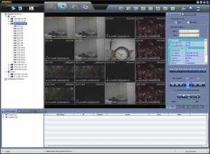
44 Screen Layout Recording Schedule Management : Site Registration & Recording Schedule Setting 2. Disk Setup : HDD/RAID Setting 3. Option Setup : Network Setting and Log Save Path Setting 4. Disconnection of File Service : Disconnection of all VOD Services to CMS * Disconnection of each VOD Service can be done by clicking the right button of the mouse, 5. Stop Recording : Stop Recording of all Recording Channels * Stop recording of each channel can be done by clicking the right button of the mouse. 6. View Server Condition : Return to Main Screen from Log Viewer Screen 7. Log Search : Go to Log Viewer Screen 8. File Search : Open File Search Screen 9. Information : Show SMS Version Information 10. VOD Status Screen : Show VOD service Status 11. Recording Status Screen : Show Recording Status of Each Site & Channel 12. HDD/RAID Status Screen : Show HDD/RAID Status 13. File Creating & Deleting Status Screen : Show Current File Creating & Deleting Status

![2) In recording schedule screen, click [Add] to open site registration/schedulessetting screen as](/docs-images/90/103719603/images/45-1.jpg "below. Input Site Name, IP Address, User ID, Password, Port, Channel and Description.")
![In case of DDNS connection, input URL as per following format. [mac address].[ddns link] : ex.](/docs-images/90/103719603/images/45-2.jpg ") 001c84010021.cctv-link.")
45 Site Registration (Recording Schedule Setup) 1) Select Recording Schedule Management icon to open recording schedule screen. 2) In recording schedule screen, click [Add] to open site registration/schedulessetting screen as below. Input Site Name, IP Address, User ID, Password, Port, Channel and Description. In case of DDNS connection, input URL as per following format. [mac address].[ddns link] : ex.) 001c cctv-link.net In order to register multi-channel for a single device such as DVR, input X Y format in Channel : ex.) 1-16 Note Maximum number of channel can be registered is 200.
![43 3) Click [Recording Setup] button. Then, recording setup screen will pop up as shown below.](/docs-images/90/103719603/images/46-0.jpg "In case of continuous recording mode, no other items are required to select except Only I-Frame Recording In case of schedule recording, user can select various recording options.")
 Schedule Recording Option - Pre Alarm : Setup Pre Alarm recording in")
46 43 3) Click [Recording Setup] button. Then, recording setup screen will pop up as shown below. In case of continuous recording mode, no other items are required to select except Only I-Frame Recording In case of schedule recording, user can select various recording options. (1) Schedule Setup Select recording method and time period by mouse click. - No Recording : Gray - Continuous Recording : Yellow - Motion Recording : Green - Sensor Recording : Orange (2) Schedule Recording Option - Pre Alarm : Setup Pre Alarm recording in connection with Motion or Sensor recording. - Post Alarm : Setup Post Alarm recording in connection with Motion or Sensor recording. Note Motion and Sensor recording requires proper setup at the correspondent device.
 It is the Key Frame with a whole picture which is compressed directly from the source like JPEG type. It has a good quality but requires a large file size.")
 After finishing all required setup, click [OK] at Recording Setup and [Apply] at Site Registration/Schedule Setting. Then, the site will be registered and shown on the list as below.")
47 44 Note Pre Alarm recording is set based on the no. of GOP. GOP means the frame group from an I-Frame to the frame just before the next I-Frame and it contains an I-Frame and a few P-Frames. * I-Frame (Intra Frame) It is the Key Frame with a whole picture which is compressed directly from the source like JPEG type. It has a good quality but requires a large file size. * P-Frame (Previous or Predicted Frame) It is made based on the previous I-Frame and has a small file. 4) After finishing all required setup, click [OK] at Recording Setup and [Apply] at Site Registration/Schedule Setting. Then, the site will be registered and shown on the list as below. Note SMS starts recording right after finishing site registration and schedule setting. And it keeps recording as per schedule as far as the program runs. 5.3 Recording Recording Status This screen shows current recording status of each site and channel. Note Record (Percentage) Each recorded file is created on 1 hour base. Therefore, the percentage will be renewed every 1 hour.

![the mouse. When [Live Monitoring] is clicked, monitoring screen will pop up as following picture. 5.4](/docs-images/90/103719603/images/48-1.jpg "VOD Service 5.4.1 VOD Status This screen shows current VOD service status of each site and channel.")

48 Live Monitoring To display current recording image of a channel, select a channel and open menu with the right button click of the mouse. When [Live Monitoring] is clicked, monitoring screen will pop up as following picture. 5.4 VOD Service VOD Status This screen shows current VOD service status of each site and channel. Connected User IP : IP address of CMS which is connected to SMS for VOD service Service Site : Site name of the recorded data Connection Info. : Time of recorded data which is being played at CMS VOD Service Information To view Information of each VOD service, select a channel and open menu with the right button click of the mouse. When [Show VOD Service Information] is clicked, information screen will pop up as following picture.
 Site Name & Channel are for the site (device) of the recorded data to search and playback. 2) IP Address, Port, User ID and Password are for those of SMS.")
49 VOD Monitoring at CMS Platform 1) In Site Registration screen of CMS, input necessary information to connect to SMS. Note 1) Site Name & Channel are for the site (device) of the recorded data to search and playback. 2) IP Address, Port, User ID and Password are for those of SMS. 2) In Monitoring screen of CMS, go to Playback mode and select date and time with calendar and/or Intelli-Search bar to find desired recorded data. And then, select site or channel and drag/drop it to monitoring screen.


50 47 Note For the detail information of using CMS, please refer to CMS User Manual. 5.5 File Search Select File Search icon to open file search screen. Select desired date and IP Address and Channel number to search. And click [Search] button to see the file list. To display recorded image of a channel, select a channel and click [Playback] button. Then, monitoring screen will pop up as following picture.
 Pop-up screen can be enlarged by double clicking of the mouse on the screen.")
51 48 Note 1) With the same procedure, multiple channels can be played with multiple pop-up screens. 2) Pop-up screen can be enlarged by double clicking of the mouse on the screen. 3 different sizes are available.
 In case that there is another drive to save, data will be saved to the next drives.")
52 HDD/RAID Setting Select Disk Setup icon to open HDD/RAID setting screen Add HDD/RAID to save file from the available disk which is shown on the right side. Note Data will be saved in alphabetical order of drives. When a drive is full, 1) In case that there is another drive to save, data will be saved to the next drives. 2) In case that there is no other drive to save or all the drives are full, new data overwrites the oldest data.
53 50 6. Trouble Shooting 1. The product doesn t work. a. Check the power supply. b. It may take about 1~2minutes to start operation. 2. No image is displayed on Internet Explorer. a. In case that the network is used by Router, check if all required ports are open. 3. Senor is activated but it doesn t work properly. a. Check the schedule setting in Video/Audio setup. It should be set as Sensor or Motion + Sensor mode. b. Check the sensor type selection (N/O or N/C) in Device setup. c. Check the contact type of the sensor. It is recommended to use dry contact type. 4. Motion is occurred on the image but it doesn t work properly. a. Check the motion sensitivity in Device setup. If the sensitivity is too low, it doesn t detect motion well. On the contrary, if the sensitivity is too high, noise of the image can be regarded as motion. b. Check the schedule setting in Video/Audio setup. It should be set as Motion or Motion + Sensor mode. 5. Under WAN network circumstance, connection to the product which has a private IP address is not available. a. Check the DMZ or port forwarding at router. For the detail, please discuss with your network administrator. b. Check the firewall setup on network. Data transmission may be restricted by the firewall. For the detail, please discuss with your administrator. c. Some of Anti-Virus program may restrict to data transmission of the product. Stop the Anti-Virus program, for a while, and try connecting again. 6. PTZ camera doesn t move. a. Check the connection cable between PTZ camera and the product. b. Check the PTZ camera supports RS-485 communication. c. Check the protocol setting in Device setup is correspondent to that of PTZ camera. d. Check the baud rate and address setting in Device setup is correspondent to that of PTZ camera. 7. A certain preset of PTZ camera doesn t work. a. The number of preset which is supported by the PTZ camera can be restricted. Check the PTZ camera manual to confirm that the preset number is supported by the PTZ camera b. There are some PTZ cameras which use a certain preset number for a special function. Check the PTZ camera manual. c. Check the preset number has a set position in Device setup and set again to confirm. 8. IRIS function doesn t work. a. Mostly, it is because the PTZ camera doesn t support IRIS function. Check the PTZ camera. b. If Auto IRIS function is activated at the PTZ camera, IRIS control doesn t work properly. Check the PTZ camera manual.
54 51 >>>>> The End <<<<<
HD NVR User Manual. High-Definition Network Video Recorder. Model : HD NVR 1 st Edition : 13 Nov nd Edition : 28 Dec Thank You!
 High-Definition Network Video Recorder HD NVR User Manual The picture & functions & supplied items might differ according to the specification and model. Contents of this user manual are protected under
RemoteManager Software
 RMS RemoteManager Software User Manual Contents of this user manual are protected under copyrights and computer program laws. Functions or configurations are subject to be changed or modified without prior
Digital Video Surveillance System
 Digital Video Surveillance System Engineering Manual The picture might differ according to the specification and model. Contents of this user manual are protected under copyrights and computer program
Digital Video Surveillance System Engineering Service Manual
 Digital Video Surveillance System Engineering Service Manual The picture might differ according to the specification and model. Contents of this manual are protected under copyrights and computer program
CMS Central Management System
 CMS Central Management System User Manual Contents of this user manual are protected under copyrights and computer program laws. Functions or configurations are subject to be changed or modified without
USER GUIDE STAND-ALONE. 4 channel MPEG-4 Triplex DVR V Stand-Alone DVR User Guide
 USER GUIDE STAND-ALONE 4 channel MPEG-4 Triplex DVR V. 1.4 This document contains preliminary information and subject to change without notice. SAFETY PRECAUTIONS EXPLANATION OF SYMBOLS This symbol is
Intelligent Security & Fire Ltd
 Digital Video Surveillance System User Manual The picture might differ according to the specification and model. Contents of this user manual are protected under copyrights and computer program laws. DVR
CMS Central Management System
 CMS Central Management System User Manual Contents of this user manual are protected under copyrights and computer program laws. Functions or configurations are subject to be changed or modified without
Single DW-BJ1NAS4T DW-BJ1NAS6T DW-BJ1NAS8T DW-BJ1NAS10T
 Single DW-BJ1NAS4T DW-BJ1NAS6T DW-BJ1NAS8T DW-BJ1NAS10T Default login Information for Blackjack NAS Username : admin Password : admin1234 Tel: +1 (866) 446-3595 / (813) 888-9555 www.digital-watchdog.com
R4, R8, R16 Digital Video Recorders Quick Setup Guide
 R4, R8, R16 Digital Video Recorders Quick Setup Guide This guide provides instructions to initially setup the R16 (16 channel) digital video recorders (DVR). The DVR supports these advanced features: 2
Make sure that you have following items supplied with your DVR. If any of these items is missing or damaged, notify your vendor immediately.
 1 1. Getting Started 1.1 Checking Supplied Items Make sure that you have following items supplied with your DVR. If any of these items is missing or damaged, notify your vendor immediately. Quick Manual
HLong Asia Industrial
 SDI DVR Stand alone digital video recorder HLong Asia Industrial Thank you for using the company's products! This manual describes only the host functions basic operation. Product design and specification
Analog High Definition DVR. Stand alone digital video recorder. User Manual H.264 AHD DVR
 Analog High Definition DVR Stand alone digital video recorder User Manual H.264 AHD DVR WARNING To reduce the risk of fire or electric shock, do not expose this appliance to rain or moisture. All the safety
USER MANUAL. Thank You!
 USER MANUAL Rev.0515 The picture might differ according to the specification and model. Contents of this user manual are protected under copyrights and computer program laws. Thank You! Before operating
4CH/ 8CH/ 16CH Digital Video Recorder
 4CH/ 8CH/ 16CH Digital Video Recorder DVR204B/ 208B/ 216B INSTRUCTION MANUAL DIRECTORY CHAPTER 1 Hard Disk Installing (Standard shipping products include neither HDD or R/W)...2 CHAPTER 2 Panel Appearance...4
Chapter 1 Features FEATURES
 Chapter 1 Features Operation Playback, recording and network transmission simultaneously Real time full screen or quad screen display 2X digital zoom and Picture-in-picture display Easy operations by shuttle
CCTV42 System2 DVR Quick Start Guide 4/8/16-Ch DVR
 CCTV42 System2 DVR Quick Start Guide 4/8/16-Ch DVR If you have purchased a DVR / Hard drive package from us then we will have already installed the hard drive(s) and configured the basic settings on your
VMS-A1 Client Software. User Manual
 VMS-A1 Client Software User Manual Contents Contents... 2 Chapter1. Overview... 4 1.1 Description... 4 1.2 Features & Functions... 4 Chapter2. Update Info... 6 Chapter3. Starting VMS-A1... 7 3.1 Installing
User Manual. Mobile Viewer Mobile Manager Software (MMS) 1 st Edition : 10 Jan nd Edition : 31 Mar rd Edition : 20 May 2010
 1 st Edition : 10 Jan nd Edition : 31 Mar rd Edition : 20 May 2010") Mobile Viewer Mobile Manager Software (MMS) User Manual The picture might differ according to the specification and model. Contents of this manual are protected under copyrights and computer program laws.
Mobile Viewer Mobile Manager Software (MMS) User Manual The picture might differ according to the specification and model. Contents of this manual are protected under copyrights and computer program laws.
IP / CCTV OUTDOOR SPEED DOME CAMERA
 242Z IP / CCTV OUTDOOR SPEED DOME CAMERA Quick Installation Guide All lead-free products offered by the company comply with the requirements of the European law on the Restriction of Hazardous Substances
RemoteManager USER S MANUAL
 Remote Monitoring Software RemoteManager USER S MANUAL Thank you for purchasing our products. Before operating the system, please read this User s Manual thoroughly and retain it for future reference.
REV: 09/30 USER MANUAL
 REV: 09/30 USER MANUAL User s Manual 2 Safety Information The safety information is provided for the wellness of the equipment and for the safety of the operator. Please review and observe all instructions
Make sure that you have following items supplied with your DVR. If any of these items are missing or damaged, notify your vendor immediately.
 1. Getting Started... 3 1.1. Checking Supplied Items... 3 1.2. User Login... 3 1.3. Time Setting and HDD Format... 4 1.4. Setup... 4 2. System Operation... 5 2.1. Using Tool(Control) Bar... 5 2.2. Display
4CH CAR D.V.R. USER'S MANUAL - Eng
 4CH CAR D.V.R USER'S MANUAL - Eng WARNIG AND CAUTIONS CAUTION : TO REDUCE THE RISK OF FIRE OR ELECTRONISC SHOCK, DO NOT EXPOSE THIS PRODUCT TO RAIN OR MOIS-TURE. DO NET INSERT ANY METALLIC OBJECT THROUGH
NVR&IPCAM USER MANUAL V1.0 (USER MANUAL) V1.0. Thanks for choosing our products, please read this manual carefully before use!
 V1.0. Thanks for choosing our products, please read this manual carefully before use!") NVR&IPCAM (USER MANUAL) V1.0 Thanks for choosing our products, please read this manual carefully before use! NOTICE Installation condition 1) In order to ensure your rights, please read this manual carefully
NVR&IPCAM (USER MANUAL) V1.0 Thanks for choosing our products, please read this manual carefully before use! NOTICE Installation condition 1) In order to ensure your rights, please read this manual carefully
HD-SDI Professional DVR Quick Guide
 HD-SDI Professional DVR Quick Guide 1. System Login 1.1 User Login Default Admin Password: 00000 1.2 Time Setting and HDD Format Navigate to {Menu} {Setup} {Time} and set the time/date to the appropriate
Stand Alone Type. Digital Video Recorder USER S MANUAL. XRS 1000 Series. This manual is written based on 1016
 Stand Alone Type Digital Video Recorder USER S MANUAL XRS 1000 Series This manual is written based on 1016 Index CHAPTER 1 Specification & System organization 1. Product Contents List --------------------------------------------------------
Make sure that you have following items supplied with your DVR. If any of these items are missing or damaged, notify your vendor immediately.
 1. Getting Started... 2 1.1. Checking Supplied Items... 2 1.2. User Login... 2 1.3. Free Login... 2 1.4. Time Setting and HDD Format... 3 1.5. Setup... 3 2. System Operation... 4 2.1. Using Tool(Control)
Pro71600N3 NVR User Manual
 Pro71600N3 NVR User Manual User Information Admin User Name: Admin Password: IP Address: System Name: Table Of Contents 1. Menu Operation...4 1.1 Main Menu...4 2. Start & Shutdown System...5 2.1 Start
Quick Start Guide 4/8/16-Ch DVR
 Quick Start Guide 4/8/16-Ch DVR 1 1. Install Hard Drive &DVD Writer 1.1Install Hard Drive Notice: 1. Support two SATA hard drives. Please use the hard drive the manufacturers recommend specially for security
Quick Start Guide 4/8-CH DVR
 Quick Start Guide 4/8-CH DVR 1 1. Install Hard Drive &DVD Writer 1.1 Install Hard Drive Notice: 1. this series support one SATA hard drives. Please use the hard drive the manufacturers recommend specially
Lorex Client 7.0 & Lorex Message Master
 Lorex Client 7.0 & Lorex Message Master Software Manual English Version 1.0 MODELS: L19WD Series www.lorexcctv.com Includes L19WD800 & L19WD1600 Copyright 2008 Lorex Technology Inc. Table of Contents Table
NUBIX H.264 DVR Setup Guide
 Package Content NUBIX H.264 DVR Setup Guide Inspect the packaging carton. Make sure the NUBIX H.264 DVR is properly delivered. Remove all items from the box and make sure the box contains the following
SmartWatch Eco/Eco Compact
 SmartWatch Eco/Eco Compact Digital Video Recorders SmartWatch Eco SmartWatch Eco Compact Quick User Guide Index Box Contents...3 Front Panel Controls...4-5 SmartWatch Eco Compact...4 SmartWatch Eco...5
H.264 4/8/10/16-Channel High-Definition DVR Quick Start Guide
 H.264 4/8/10/16-Channel High-Definition DVR Quick Start Guide Products: BLK-HD4D, BLK-HD4E, BLK-HD8D, BLK-HD10D, BLK-HD16D BLK-HD4E (upper) BLK-HD4D and BLK-HD8D (middle) BLK-HD10D and BLK-HD16D (lower)
DVR RANGE ENGINEER MANUAL
 INSPIRE DVR RANGE ENGINEER MANUAL Contents Hardware Inspire DVR range Connections Connecting a mouse Connecting keyboard Connecting PTZ cameras Connecting Keyboard/PTZ Alarm connections Using front panel
USER GUIDE VCT-STDDVR9-1 = /16 channel MPEG-4 Triplex DVR V. 1.0
 USER GUIDE VCT-STDDVR9-1 = 16-1 9/16 channel MPEG-4 Triplex DVR V. 1.0 This document contains preliminary information and subject to change without notice. 2 SAFETY PRECAUTIONS EXPLANATION OF SYMBOLS This
DVR SYSTEM User s Manual
 DVR SYSTEM User s Manual Manual Revision : Version 5.3 above Release Date : July 1. 2004 INDEX Chapter. Main Screen -1. Explanation of Main Screen A ~ N Functions per button -2. Pan/Tilt Control O Pan/Tilt
Zavio P5111/ P5116/ P5210 Quick Installation Guide
 86085M2000010 Zavio P5111/ P5116/ P5210 Quick Installation Guide Installation Steps Please follow the installation steps below to set up your P5111 / P5116/ P5210 Day/Night Pan/Tilt IP Camera. Check the
Pro7804N1 NVR User Manual
 Pro7804N1 NVR User Manual Pro7804N1 User Manual BW R6.indd 1 User Information Admin User Name: Admin Password: IP Address: System Name: Table Of Contents 1. Menu Operation...4 1.1 Main Menu...4 2. Start
Quick Start Guide 4/8/16-Ch DVR
 Quick Start Guide 4/8/16-Ch DVR 1 1. Install Hard Drive &DVD Writer 1.1Install Hard Drive Notice: 1.This series support one SATA hard drive. Please use the hard drive the manufacturers recommend specially
User s Guide. Combo DVR. Thank you for purchasing our product. Please read this User s Manual before using the product. Change without Notice
 Thank you for purchasing our product. Please read this User s Manual before using the product. Change without Notice Combo DVR User s Guide User please operate according to the DVR model that you purchased
DDR-08 DDR-16 Full D1 Realtime H.264 DVR 8 / 16 CH. Quick Setup Guide
 DDR-08 DDR-16 Full D1 Realtime H.264 DVR 8 / 16 CH. Quick Setup Guide PACKAGE CONTENTS A. One (1) DDR-08 / DDR-16 DVR B. One (1) Remote Controller C. Two (2) AAA Battery for Remote Controller D. One (1)
GV-IP Decoder Box Plus User s Manual
 GV-IP Decoder Box Plus User s Manual Before attempting to connect or operate this product, please read these instructions carefully and save this manual for future use. DBPV10-UM-A 2015 GeoVision, Inc.
SPECIFICATIONS ARE SUBJECT TO CHANGE WITHOUT PRIOR NOTICE. THE INFORMATION CONTAINED HEREIN IS TO BE CONSIDERED FOR REFERENCE ONLY.
 COPYRIGHT 2010 by AVerMedia Information, Inc. All right reserved. Reproduction without permission is prohibited. No part of this document may be reproduced or transmitted in any form, or by any means without
4CH Real Time DVR. User Guide INFORMATION MAY CHANGE WITHOUT NOTICE. Digital Video Recorder
 User Guide INFORMATION MAY CHANGE WITHOUT NOTICE. Table of Contents Caution... 4 Package Contents... 4 Introduction... 5 1. Product Overview...5 2. Front Panel...5 3. Rear Panel...6 4. IR Remote Controller
AVerMedia IWH3216 Touch Quick Installation Guide
 AVerMedia IWH3216 Touch Quick Installation Guide NOTICE SPECIFICATIONS ARE SUBJECT TO CHANGE WITHOUT PRIOR NOTICE. THE INFORMATION CONTAINED HEREIN IS TO BE CONSIDERED FOR REFERENCE ONLY. WARNING TO REDUCE
Standard H.264 DVR Setup Guide
 Package Content Standard H.264 DVR Setup Guide Inspect the packaging carton. Make sure the Standard H.264 DVR is properly delivered. Remove all items from the box and make sure the box contains the following
AVI321 / 311 Network Camera Series Quick Guide
 242Z AVI321 / 311 Network Camera Series Quick Guide All lead-free products offered by the company comply with the requirements of the European law on the Restriction of Hazardous Substances (RoHS) directive,
Video surveillance kit PNI House WiFi 400
 Video surveillance kit PNI House WiFi 400 NVR and 4 wireless cameras USER MANUAL NVR menu (Android / ios) app Software HCMS (Windows) IP CAMERA: NVR: 1 2 3 4 5 1 2 3 4 5 6 1 - Antenna 1 - Antenna connector
Quick Start Guide 4/8/16-CH DVR.
 Quick Start Guide 4/8/16-CH DVR 1. Install Hard Drive &DVD Writer 1.1 Install Hard Drive Notice: 1. Support two SATA hard drives. Please use the hard drive the manufacturers recommend specially for security
Lite H.264 DVR Setup Guide
 Package Content Lite H.264 DVR Setup Guide Inspect the packaging carton. Make sure the Lite H.264 DVR is properly delivered. Remove all items from the box and make sure the box contains the following items.
RAS (Remote Administration System)
") RAS (Remote Administration System) Digital Video Recorder Software User Guide Document 900.0314 Rev 2.00 RAS User Guide Revisions Issue Date Revisions 1.00 08/04 New document. 1.01 04/05 Update template,
RAS (Remote Administration System) Digital Video Recorder Software User Guide Document 900.0314 Rev 2.00 RAS User Guide Revisions Issue Date Revisions 1.00 08/04 New document. 1.01 04/05 Update template,
Video Web Server. User s s Manual MPEG-4 VIDEO WEB SERVER. Please read instructions thoroughly before operation and retain it for future reference.
 13 Video Web Server MPEG-4 VIDEO WEB SERVER User s s Manual Please read instructions thoroughly before operation and retain it for future reference. 733_V0.95 Thank-You Note Before You Get Start First
BlackHawk for MAC Software User Guide
 BlackHawk for MAC Software User Guide Products: BLK-DH2 Series and BLK-HD Series DVRs Please read this manual before using your software, and always follow the instructions for safety and proper use. Save
- For pluggable equipment, the socket-outlet shall be installed near the equipment and shall be easily accessible.
 1 H.264 Digital Video Recorder Safety Information The safety information is provided for the wellness of the equipment and for the safety of the operator. Please review and observe all instructions and
The Intelligent Surveillance Solution NVR. User Manual. Ver
 The Intelligent Surveillance Solution NVR User Manual Ver. 2.0.0.140325.00 Table of Contents 1. Installation... 8 1.1 Installation Process... 8 1.2 LED Status Definitions... 16 2. Settings... 17 2.1 Camera
960H H.264 DVR Setup Guide
 Package Content 960H H.264 DVR Setup Guide Inspect the packaging carton. Make sure the 960H H.264 DVR is properly delivered. Remove all items from the box and make sure the box contains the following items.
NVMS User Manual
 NVMS-1000 User Manual Contents 1 Software Introduction...1 1.1 Summary... 1 1.2 Operation Environment... 1 1.3 Install and Uninstall... 2 1.3.1 Install the Software... 2 1.3.2 Uninstall the Software...
Quick Start Guide 4/8/16/24-Ch DVR
 Quick Start Guide 4/8/16/24-Ch DVR 1.1 Install Hard Drive 4/8/16/24-CH DVR Quick Start Guide Notice: 1.4/3/16-ch DVR supports one SATA hard drive. 24-ch DVR supports three SATA hard drives. Please use
Client Software-4000(V ) User Manual
 User Manual") Client Software-4000(V2.00.02) User Manual Index Chapter 1 Welcome to Client Software-4000 (V2.0)... 1 1.1 Overview... 1 1.2 Computer Disposition Request... 1 1.3 Convention... 1 Chapter 2 Install & Uninstall...
Client Software-4000(V2.00.02) User Manual Index Chapter 1 Welcome to Client Software-4000 (V2.0)... 1 1.1 Overview... 1 1.2 Computer Disposition Request... 1 1.3 Convention... 1 Chapter 2 Install & Uninstall...
QSD2308L/QSD2316L DVR User s Manual
 QSD2308L/QSD2316L DVR User s Manual NOTE: We use two different front panel designs on these models. They have the same function buttons but they are arranged differently. Please match the front panel on
IP Mini PTZ CAMERA USER GUIDE
 IP Mini PTZ CAMERA USER GUIDE TYPE A: To switch the mount style, remove the two screws on the pan bottom and rotate 180 degree to remount. This Mini PTZ cylinder camera can support both wall mount and
Network Video Recorder Quick Operation Guide
 Network Video Recorder Quick Operation Guide UD.6L0202B1351A01 TABLE OF CONTENTS NVR Pre-Installation... 2 NVR Installation... 2 Hard Disk Installation... 2 Front Panels... 6 DS-9500NI-ST/RT Front Panel...
4Ch Real time / Triplex / Mux Stand Alone DVR
 4Ch Real time / Triplex / Mux Stand Alone DVR User s Manual VER 1.2 VSD-31 4 Channel Stand Alone DVR USB Backup available The most stable and reliable real stand alone Digital Video Multiplex Recorder
LOREX CLIENT 3.0 SOFTWARE MANUAL IRMS Integrated Remote Management Software
 LOREX CLIENT 3.0 SOFTWARE MANUAL IRMS Integrated Remote Management Software Instruction Manual English Version 2.0 Copyright 2007 Lorex Technology Inc. www.lorexcctv.com Table of Contents Overview... -
NVMS1000. User Manual
 NVMS1000 User Manual Contents 1 Software Introduction... 1 1.1 Summary... 1 1.2 Operation Environment... 1 1.3 Install and Uninstall... 2 1.3.1 Install the Software... 2 1.3.2 Uninstall the Software...
IP Camera User Manual
 Statement IP Camera User Manual If the user manual cannot help you to solve the problem, please call our technology center about the solutions. We will update the content for the new functions without
ALIBI Witness 2.0 v3 Smartphone App for Apple ios Mobile Devices User Guide
 ALIBI Witness 2.0 v3 Smartphone App for Apple ios Mobile Devices User Guide ALIBI Witness 2.0 v3 is a free application (app) for Apple ios (requires ios 7.0 or later). This app is compatible with iphone,
VIDEO WEB SERVER. User s Manual. Please read instructions thoroughly before operation and retain it for future reference. PATENT 732 V1.
 VIDEO WEB SERVER PATENT User s Manual Please read instructions thoroughly before operation and retain it for future reference. 732 V1.0 WARNING The apparatus shall not be exposed to dripping or splashing
- for pluggable equipment, the socket-outlet shall be installed near the equipment and shall be easily accessible
 1 VMAX IP User Manual Safety Information The safety information is provided for the wellness of the equipment and for the safety of the operator. Please review and observe all instructions and warnings
NVMS1000. User Manual
 NVMS1000 User Manual Contents 1 Software Introduction... 1 1.1 Summary... 1 1.2 Operation Environment... 1 1.3 Install and Uninstall... 2 1.3.1 Install the Software... 2 1.3.2 Uninstall the Software...
- For pluggable equipment, the socket-outlet shall be installed near the equipment and shall be easily accessible.
 1 H.264 Digital Video Recorder Safety Information The safety information is provided for the wellness of the equipment and for the safety of the operator. Please review and observe all instructions and
960P and 1080P HD Video Security DVR System User Manual
 960P and 1080P HD Video Security DVR System User Manual www.tigersecu.com Copyright 2017 TIGERSECU, Inc Contents Contents... 1 Important Information...3 Installation Guide....4 Chapter 1. Start-up Wizard...6
Video Management Software
 Video Management Software User Manual Web: europesecurity.eu Mail: info@europesecurity.eu Tel.: 0541 352 952 User s Manual 2 Contents CHAPTER : XMS CENTRAL USER MANUAL 1 PC REQUIREMENT 3 2 INSTALL 3 3
TruVision DVR 60 Quick Start Guide
 Content Package contents 1 Installation environment 1 Setting up the TVR 60 1 Connecting the devices 2 Turning on and off the TVR 60 2 Operating the TVR 60 3 DDNS settings 5 Live mode 5 Quick Archive 5
ALL-IN-ONE SECURITY SYSTEM
 DO NOT OPEN CAUTION : TO REDUCE THE RISK OF ELECTRICAL SHOCK DO NOT OPEN COVERS. NO USER SERVICEABLE PARTS INSIDE. REFER SERVICING TO QUALIFIED SERVICE PERSONNEL. WARNING : TO PREVENT FIRE OR SHOCK HAZARD.
OIPC72B7G Owner s Manual
 Owner s Manual OIPC72B7G Rev.1.2 (Oct. 2012) 1 Directions Be careful not to cause any physical damage by dropping or throwing OIPC72B7G. Especially keep the device out of reach from children. Do not disassemble
- for pluggable equipment, the socket-outlet shall be installed near the equipment and shall be easily accessible
 Safety Information The safety information is provided for the wellness of the equipment and for the safety of the operator. Please review and observe all instructions and warnings in this manual. Note
User s Manual November 2004 V 1.1
 User s Manual Please read instructions thoroughly before operation and retain it for future reference. November 2004 V 1.1 WS2 WARNING The apparatus shall not be exposed to dripping or splashing and that
Installation Instructions Fig. 3 Side View. No. Label Operation
 One-Camera IP Video Server In G Out G D+ D- Installation Instructions 1507280 Part Number: CM2002 - One-Camera IP Video Server CM2002 IP Video Server Features In G Out G D+ D- DO G DI G Out In Video In
USER MANUAL. Mac Version
 USER MANUAL Mac Version Contents 1 Software Introduction... 1 1.1 Summary... 1 1.2 Install and Uninstall... 1 1.2.1 Install the Software... 1 2 Login Software... 3 2.1 Login... 3 2.2 Control Panel Instruction...
Pro7400H1 Hybrid DVR User Manual
 Pro7400H1 Hybrid DVR User Manual User Information Admin User Name: Admin Password: IP Address: System Name: Table Of Contents 1. Menu Operation... 4 1.1 Main Menu... 4 2. Start Up/Shutdown System... 5
Digital Video Recorder User Manual. DVR User Manual. For H channe/ 8-channel/16-channel Digital Video Recorder All rights reserved
 DVR User Manual For H.264-4-channe/ 8-channel/16-channel Digital Video Recorder All rights reserved i CAUTION Please read this user manual carefully to ensure that you can use the device correctly and
DVR/NVR OS User Manual Ver
 DVR/NVR OS User Manual Ver. 2016-11 Chapter 1. DVR / NVR Operation Setup... 3 1-1 Power ON.... 3 1-2 Storage Setup... 3 1-3 Recording Setup... 4 1-4 Date/Time Setup... 4 1-5 Display Setting and Other Setup...
DHE-04 DHE-08 DHE H H.264 DVR 4 / 8 / 16 CH. Quick Setup Guide PACKAGE CONTENTS A. B. C. D. E. F. G. H. Inside the DVR I.
 960H H.264 DVR 4 / 8 / 16 CH. Quick Setup Guide DHE-04 DHE-08 DHE-16 PACKAGE CONTENTS A. One (1) DHE-04 / DHE-08 / DHE-16 DVR B. One (1) Remote Controller C. Two (2) AAA Battery for Remote Controller D.
Configuring and Managing the IP Camera
 CHAPTER 3 The Cisco Video Surveillance IP Camera provides configuration windows that you use to configure and manage the IP camera. This chapter explains how to access the configuration windows, describes
DESCRIPTION Enter user name provided by ISP Enter password provided by ISP
 User name Password ICON Enter user name provided by ISP Enter password provided by ISP 4-5-2. HTTP 4-5-3. DDNS ICON Startup HTTP Check to enable HTTP server. Users can remotely access into the DVR over
QSTD2404/QSTD2408/QSTD2416 Digital Video Recorders User s Manual
 QSTD2400 Series DVR User s Manual QSTD2404/QSTD2408/QSTD2416 Digital Video Recorders User s Manual For H.264-4-channel/ 8-channel/16-channel Digital Video Recorders All rights reserved Rev 091708 i QSTD2400
EH6000H series EH6108H + /EH6216H + Quick User Guide
 EH6000H series EH6108H + /EH6216H + Quick User Guide COPYRIGHT COPYRIGHT 2011 AVer Information Inc. All rights reserved. No part of this document may be reproduced or transmitted in any form, or by any
AVE DR16X / AVE DR8X Quick Installation Guide
 AVE DR16X / AVE DR8X Quick Installation Guide Package Content Inspect the packaging carton. Make sure your AVE DR16X / AVE DR8X is properly delivered. Remove all items from the box and make sure the box
AVerMedia. AverDiGi EH5116 PRO. Quick Installation Guide
 AVerMedia AverDiGi EH5116 PRO Quick Installation Guide i SPECIFICATIONS ARE SUBJECT TO CHANGE WITHOUT PRIOR NOTICE THE INFORMATION CONTAINED HEREIN IS TO BE CONSIDERED FOR REFERENCE ONLY WARNING TO REDUCE
NVMS-7000 Client Software User Manual Version 1.03
 NVMS-7000 Client Software User Manual Version 1.03 Contents Chapter 1. Overview... 3 1.1 Description... 3 1.2 Running Environment... 3 Chapter 2. Starting NVMS-7000... 4 2.1 User Registration... 4 2.2
DVR CH Digital Video Recorder SW242-LP4 / SW242-LPN
 DVR4-1100 4CH Digital Video Recorder SW242-LP4 / SW242-LPN User Manual INDEX 1. DVR Features... 1 2. Layout 2.1 Front Panel...1 2.2 Rear Panel...2 2.3 Remote Controller...2 3. Installation 3.1 Installing
SAFEGUARD CONTENTS. Digital Video Recorder. Version 1.3. Page. DVR Server S A F E G U A R D
 S A F E G U A R D SAFEGUARD Digital Video Recorder Version 1.3 CONTENTS Chapter 1 Chapter 2 Chapter 3 3.1 3.2 3.3 3.4 3.5 3.6 3.7 3.8 3.9 Chapter 4 4.1 4.2 Remote Client Chapter 5 Chapter 6 Chapter 7 7.1
H.264 Network DVR. Quick Start
 H.264 Network DVR Quick Start GUI Display with USB Mouse Control Please read instructions thoroughly before operation and retain it for future reference. For the actual display & operation, please refer
TENVIS Technology Co., Ltd. User Manual. For H.264 Cameras. Version 1.0.0
 TENVIS Technology Co., Ltd User Manual For H.264 Cameras Version 1.0.0 Catalogue Basic Operation... 3 Hardware Installation... 3 Search Camera... 3 For Internet Explorer... 6 Playback Record Files... 9
Downloaded from manuals search engine
 INDEX 1. DVR Features...1 2. Layout 2.1 Front Panel...1 2.2 Rear Panel...2 2.3 Remote Control...2 3. Installation 3.1 Installing the Hard Drive...3 3.2 Connecting Camera and Monitor...3 3.3 Connecting
User s Manual V 0.96
 User s Manual V 0.96 1 Regulatory Information FCC compliance: This equipment has been tested and found to comply with the limits for a digital device, pursuant to part 15 of the FCC Rules. These limits
USER S MANUAL GV-DVR1042. Real Time DVR System. Stand Alone 4 Channel.
 USER S MANUAL GV-DVR1042 Stand Alone 4 Channel Real Time DVR System www.gviss.com 1 B E F O R E I N S T A L L A T I O N - - - - - - - - - - - - - - - - - - - - - - - - - - - - - - - - - - - - - - - - -