James Instruments Inc. R- Meter Mk III Complete System
|
|
|
- Roderick Doyle
- 5 years ago
- Views:
Transcription

1 James Instruments Inc. R- Meter Mk III Complete System
2 General Overview The James Instruments R-Meter MK III utilizes the latest in eddy current sensing and micro-processor technology to accurately locate, determine depth, and estimate size of metal objects in concrete. The eddy current sensor is specifically designed to react to the outer surface of the metal object only. It is uninfluenced by small particles in the concrete, whether the concrete is fresh or hardened, dry or wet. Built in modes for rebar, conduit, copper pipe, and post tension cable facilitate the use of the R-Meter Mk III. This allows the unit to locate both ferrous as well as non-ferrous metals in concrete. The latest in microprocessor technology not only conditions the sensor signal but provides the user with the size of steel reinforcing bar, depth of steel reinforcing, a map of cover and more. The unit's easy to view display can provide the user with a complete structural analysis. An easy to use bar display and an audio headphone tone helps to quickly and accurately locate metal objects. Large easy to view numbers display an instantaneous estimate of cover. It will also display a map of cover throughout the structure. Further options will allow a cross-section of the concrete structure under test. The R-Meter MK III was developed for real world application and every day durability in mind. It's rugged and splash resistant case allows the user to use the R-Meter Mk III in the field. It's small but very sturdy sensing probe can withstand test after test with little wear on the probe face. The R-Meter Mk III enables the user to store his field data and later download it to a P.C.software. This P.C. software receives the data then allows the user to analysis it. A graphing tool allows the creation of a contour map.
3 Technical Specification Sensor Dimensions: 5"L x 2.4" W x 1.6" H Sensor Weight: 1lb Instrument Dimensions: " L x 9.68" W x 4.875" H Instrument Weight: 5.4 lbs Complete System Weight: 10 lbs Basic System Weight: 8 lbs LCD Dimension: 3.5" L x 4.65 " H LCD Size: 320 x 240 pixels Operating Temperature: C Standard Imperial Rebar Sizes: 3, 4, 5, 7, 9, 10, 11 Standard Metric Rebar Sizes: 10mm, 12mm, 20mm, 25mm, 30mm, 34mm Standard Copper Pipe Sizes:.375,.500,.750, 1.00, Standard Conduit Sizes:.750, 1.00, Power Source: 12v, 4-6hr continuous use

4 Data logger Unit The data logger unit, which is a standard with the James Instruments R-Meter Mk III, is a sophisticated ruggedized field proven unit. The embedded microprocessor technology enables the end user to easily locate, determine cover, record, and analyze ferrous and non- ferrous metals. The data logger's easy to view display can provide the user with a complete structural analysis instantaneously. Large bold easy to view numbers on the display makes the R-meter MK III very user friendly when estimating cover or bar size. A memory capacity of 8000 data points allows a large sum of data to be stores for later analysis. The front panel of the data logger unit (pictured below) allows the end user to interface with the sensor probe, scancart, headphone, charger and a personal computer via a RS-232 port. A large viewing window protects the LCD display from possible damages that may occur during operation. Large control buttons on the front panel enables the user to easily scroll through menu options. Power Key - Momentarily push this key to turn on the unit. Pressing it again turns off the unit. The unit will power up displaying the main menu screen when powered up. Back light Key - Depressing this key the backlight of the display comes on. Depressing the key again turns the backlight off. Enter Key - Pressing this key allows you to choose main menu selections. The enter key also allows you to prepare the R-Meter MK III for operation.
5 Escape Key- Pressing this key allows you to return to the main menu screen from any sub screen. Up arrow Key - This key is used to scroll through various settings and wave frames. Down arrow Key - This key is used to scroll through various settings and wave frames. Right arrow key - This key allows you to scroll through various settings. Left arrow key- This key allows you to scroll through various settings
6 Probe The James Instruments R-Meter Mk III utilizes the latest in eddy current sensing technology to accurately locate, determine depth, and estimate size of metal objects in reinforced concrete structure. The eddy current probe has been specifically designed to react to the outer surface of the metal object only. The ability to determine cover, locate, and estimate bar size in both deep and short mode with a single probe makes the R-Meter MKIII sensing probe far more superior than any other commercially available rebar location systems. The R-meter Mk III sensing probe is compact,weighing only 1 lb and dimensioned at 5"x 2.4"x1.6" and still very tough and durable for field application. The sensing probe has been calibrated in our facility only for operation with the data logger unit it was purchased with. If a new sensor probe is needed it is recommended to send the complete unit for proper calibration. Not calibrating the sensor probe and the data logger unit together can cause unacceptable location, cover, and bar size readings. For further information regarding repair and calibration please contact our office.
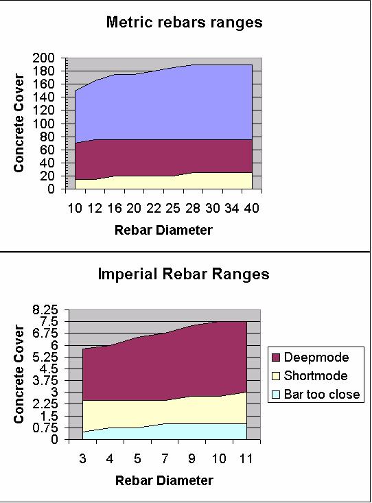
7 Short /Deep mode The R-meter Mk III facilitates analysis of rebar location, cover, and bar sizing by allowing the user to do measurements in a short mode or deep mode. The R-meter MkIII provides the user the ability to decide whether the system switches from deep and short mode automatically or manually, to do so follow the following direction. No switching of probes is required, as the single sensing probe operates efficiently in both modes. When the system is initially turned on the automatic ranging is the default. To change this setting go to the locate /cover menu screen this is needed as this function can only be done in the locate/cover screen. Once in locate/ cover screen use the up or down arrow keys on the front panel to scroll the highlight to the locate option. While the highlight is on the LOCATE option press the left arrow key once. The letters RS will appear on the upper left hand corner of the screen. The letters RS indicate that auto ranging is on. Do the same procedure to turn off auto ranging and have the ability to manually switch ranges. Short mode: Ideal when reinforcement cover ranges form.5" to 3.0". Locating, determining cover and bar size can all be measured while in this mode. An error of ±.125 must be accounted for during measurement of metal bar or pipe location. Deep mode: Ideal when reinforcement cover ranges from 2.75" to 8. Locating, determining cover and bar size can all be measured while in this mode. An error of ±.125 must be accounted for during measurement of metal bar or pipe location.
8
9 Locating Ferrous and non-ferrous metals The R-meter MK III using the latest in eddy current sensing and microprossing technology is ideal for locating ferrous and non-ferrous metals. Metals that can be located with ease are the following - Imperial and Metric reinforcement bars - Standard copper pipe - Standard conduit pipe - Post tension cable The R-meter MkIII allows the user to locate metals by using two options on the LCD display. Option 1 A bar displays on the top of the location screen enables the user to determine when the center of the metal bar/pipe has been detected. When this bar display reaches the center of the metal bar/pipe it will be have incremented to its highest point, once the sensing probe has passed the center of the metal bar/pipe the bar display will increment down. Option 2 This option consists of a numerical output displayed on the location screen. The range of this number is 0 to As the probe moves toward the rebar/pipe the number will increase, when the probe is over the center of the rebar /pipe you will see the largest number displayed. As you move the probe away from the center of the rebar/pipe the number will start to decrease. This technique can also be useful in determining whether a short or deep mode is necessary for proper location, cover, and sizing analysis should be used.


10 Determining Cover The R-Meter MkIII allows the operator to easily determine concrete cover of rebar. Since the R- Meter MkIII utilizes eddy current technology cover is determined with even more accuracy than predecessor, because of the eddy current technology only the bar/pipe is located and no small particles of metals in the concrete can influence the measurement. Such as flyash. The following steps allow for proper cover measurements Step 1: The first thing to do is to choose either English or Metric modes on the system menu screen. Step 2: Choosing whether short or deep mode range is necessary for your operation. This can be done on the locate/cover screen, for a more detailed explanation link to short mode / deep mode ranges. Step 3: Using the down arrow key scroll the highlight 4 lines down to the bar diameter category. Once this line is highlighted use the right or left arrow keys to choose the bar diameter. Step 4: Now pass the sensing probe on the surface of the structure until the smallest cover is displayed on the right hand corner of the screen.


11 Step 5: The R-Meter Mk III allows the user to choose the minimum cover to analyse with. This feature is refered to as the Smin. Using the up or down arrow key scroll the highlighter down to the Smin categorie and use the left or right arrow keys to choose an Smin that ranges from Step 6: Now pass the sensing probe on the surface of the structure until the smallest cover is displayed on the right hand corner of the screen. The audio/ headphone feature also allows the user to precisely locate the center of the rebar using audio signal. This audio feature helps give even more cover precision. your application. The steps below shows how to properly choose the audio signal for Step 6A: In the Locate Cover screen use the up / down arrow keys to scroll the cursor down to the laction bar. Step 6B: Use the right arrow key to choose either a beeping type audio signal or a continuous tone audio signal. A small speaker icon will appear on the upper right hand corner when the audio feature has been enabled. Head phones have also been supplied with the R- meter Mk III to help the user hear a clearer audio signal. Step 6C: Pressing the right arrow key one more time after the continues tone will turn off the audio feature, also the speaker icon on the upper right hand corner will no longer appear on hte display screen.
12 Determine Bar Size The bar diameter can be easily determined with the R-Meter MkIII with out the prior knowledge of cover. This is possible by taking two reading one at surface of the structure and another at the same location but.750 inches away. A.750 spacer is provided with the system a long with a locating template that helps keep the exact location of the first reading when doing the second reading with the.750 spacer. The following steps allow for proper bar sizing measurements Step 1: Press ESC once in the Locate Cover screen. Step 2: Once in the Main menu screen use the up or down arrow keys to navigate the highlight to the Locate category. Step 3: Using the right arrow key on the front panel choose Size and press enter. Step 4: In the BAR SIZE screen choose which range (short or deep) you will be operating in, this is done by pressing the right arrow key. The system will alternate ranges each time the key is depressed. Step 5: Using the sensor probe locate the center of the rebar by either using the bar display or the numerical output. Once the center has been determined press enter.
13 Step 6: The R-Meter Mk III will now read ADD BLOCK - PRESS ENT on the top line. Step 7: At this point the locating template needs to be applied over the sensor probe. Keeping the locating template positioned exactly where the sensing probe (center of the bar) is very important. Remove the sensing probe and place the 3/4 inch spacer in the center of the locating template. Now place the sensing probe over the 3/4 inch spacer. Step8: press enter The R-Meter MkIII will now display the estimated diameter of the rebar which was measured. The R-Meter MK III can accurately determine bar size up to 4.5" (115mm) in the deep range.

14 Pitch & Resolution Measurements can often be influenced by neighboring parallel bar. The graphs below shows the min spacing to it's corresponding bar.

15 Utilizing Cover Map function The James Instruments R-Meter Mk III has incorporated a user friendly cover map to further assist in field analysis. The cover map mode allows the user to mark the cover and location of a rebar on a grid. The grid lines are numerically numbered with the Y axis starting at 1 from left to right. The X axis is also numerically numbered with number 1 starting at the top of the grid. The Three symbols below have been selected to allow the user to distinguish the status of the current reading. A full shaded box represents that the cover has exceeded that of the selected S min. The S min is the selected minimum cover you have told the R-Meter MkIII to detect. A box with 3 thick shaded lines means that the cover is within range of the selected S min. A box with 3 thin inner lines means that the R-Meter Mk III has not detected a bar/tube. Please follow this procedure to correctly prepare the R-Meter Mk III for Cover Map operations. Step 1: Press the escape key on the front panel to get to the Main Menu screen. Step 2: Navigate the highlighted cursor using the up or down arrow keys to COVER MAP MENU option and press enter. Step 3: Choose whether you would like to INSTALL NEW MAP or VIEW OLD MAP by highlighting one and pressing enter.
16 Step 4: If view a map is chosen please proceed to step 4B, if not please follow the instruction directly below for installation of a new map. Step 4A: 1) The R-Meter Mk III automatically generates a map number. 2) Under the Material categorie line choose the material under investigation. (rebar, conduit, copper) 3) Choose the diameter of the material under investigation. 4) Choose the S min (minimum cover) 5) Choose the detection range DEEP or SHORT that cover analysis will be done in. 6) Press enter 7) The screen now displays the cover map grid.
17 Step 4B: 1) After choosing to view old map a REVIEW COVER MAP menu screen will appear. 2) The system does not allow adjustment of previous set parameters. 3) The only function that can be changed is that of which map to view. 4) Choose the map number to view and press enter. 5) The screen now displays the cover map grid with previously saved data. New data can be saved into the gridded map along with the older data. Step 5: Utilizing the Up or Down arrow keys on the front panel chose the location for your first mark. Step 6: Pass the sensing probe over the area being investigated; the blinking cursor will turn into one of the three cover symbols. Step 7: Pressing the enter key will save that symbol onto the screen and memory along with location information which is on the bottom of the screen. This information will appear for this particular point on the upload screen of the PC software.
18 System Menu The system setup option on the main menu screen allows you to make modifications to system configurations. Once in the system setup sub menu modification can be made to the following -Display -Language -Units -Clock menu -Erase Memory -Battery operation Pressing the escape key takes you back to the main menu screen.
19 Erase Memory To erase store memory from the R-Meter MK III follow these steps Press the up or down key until you get to the system setup menu option. Press Enter. The Setup Menu sub screen should appear. SETUP MENU Scroll through the Setup menu using the up or down arrow key. Select the Erase Memory option by pressing Enter. The display should read the following. ERASE MEMORY Press enter once a message telling you to press enter again should appear. PRESS ENTER AGAIN Pressing enter a second time will erase all stored memory in the R-Meter MK III system Pressing the Escape key will return you to the Main Menu Screen.

20 Display Cursor To change the visibility of the display cursor follow these steps Press the up or down key until you get to the system setup menu option. Press Enter. The Setup Menu sub screen should appear. Scroll through the Setup menu using the up or down arrow key. Select the Display option by pressing enter. The display should read the following. DISPLAY= Pressing the left or right arrow keys will give the option to choose Black Lines or White Lines. Pressing the Escape key will return you to the Main Menu Screen.

21 Language Options To choose which Language the R-Meter MK III will be operating in follow these steps Press the up or down key until you get to the system setup menu option. Press Enter. The Setup Menu sub screen should appear. Scroll through the Setup menu using the up or down arrow key. Select the Language menu option by pressing enter. The display should read the following. LANGUAGE= Use the left or right arrow keys to choose English or Spanish as the language that your R-Meter MK III operates in. Pressing the Escape key will return you to the Main Menu Screen.
22 Measuring Units English and Metric units are available for the user to choose from. The following steps allow the user to choose the measuring unit he wants to operate in. Step 1: In the main menu screen use the up or down arrow keys on the front panel to navigate down to the system set up category. Step 2: Press enter. Step 3: In the system set up screen use the up or down arrow keys on the front panel to navigate down to the UNIT category. Step 4: Use the right arrow key to choose either Imperial (English) or metric measuring units. Step 5: Press the ESC key to go back to the main menu screen and continue measurements.

23 Clock Menu To change date and time please follow these steps Press the up or down key until you get to the system setup menu option. Press Enter. The Setup Menu sub screen should appear. Scroll through the Setup menu using the up or down arrow key. Select the Clock Menu option by pressing enter. The display should read the following. Pressing the left or right arrow key will increment the digits on the display. Use the up and down key to select each hour and date options. Scroll to the save changes option using the up or down arrow key.
24 Pressing the enter key will store the date and time and return you to the Main menu screen


25 Battery A 15V rechargeable battery is included in the R-Meter MK III. At full charge the main menu will display BATTERY=100%. Monitoring of the battery can be done by entering the battery operation mode in the system menu screen. In this mode the charge and discharge of the battery can be monitored. The system is operational when the charger is supplying power except when in the following screens. -Locate cover -Bar size -Cover map It is recommended to charge the unit before any lengthy field test is done. By hitting enter the battery and charger register are cleared and your battery percentage will reset to its actual reading. Battery running time is at 4-hour minimum for a continuous field test. Replacing or repair of battery should be done by trained James Instruments technician and should be sent to our repair department for service.
26 Upload Data The upload function of the R-meter Mk III is available for all models except the basic model R-C Please detail whether you require upload capabilities at time of order. Please follow the steps bellow in order to upload the data stored in the data logging unit to a P.C. Connect the unit to the correct serial port of the P.C. using the supplied serial cable. Press the up or down key until you get to the upload menu option. Press Enter. The upload sub screen should appear. Scroll through the upload sub menu using the up or down arrow key. Select which upload menu function you would like to perform by pressing Enter. The display should read the following UPLOAD SCAN MAP (only with upgraded model R-C-3075) UPLOAD ALL SCAN MAPS (only with upgraded model R-C-3075) Use the up or down arrow key to select an upload. Pressing the left or right arrow key you can select which number of test data you want uploaded. Pressing Enter the upload process will begin. Go to the P.C software and press the download icon. P.C. software will display waiting for data.
27 Go to the R-Meter Mk III and press the enter key. During Test upload the displays reads Upload In Progress Once the upload has been completed the display will read " Upload complete Pressing the Escape key will return you to the Main Menu screen.
28 Tools Upload (Ctrl+U) This command is used to upload data from data logger unit to the CPU. For Proper upload of data to a P.C. please follow these steps Open the R-Meter Mk III software ("R-Meter MK III" will appear on the upper left corner) on the P.C. Connect P.C and R-Meter Mk III by the RS serial ports. On the R-Meter MK III scroll down to the Upload menu Press enter. Choose which stored data test you want to download. Go to the R-Meter Mk III software (needs to be installed on P.C.) click on the upload Icon or press CTRL + U. R-Meter Mk III software will ask you to Please start upload ". At this moment press the enter key on the R-Meter Mk III (R-Meter MK III software waits 50 seconds for the upload information.) If no data is received after 50 seconds a No data received sub screen will appear. Data will appear on the screen after all data has been transferred. Save data in desired folder. Ports This command allows setting the correct (RS-232) com port. It can be com1 through com 4. The default setting is com 1. Graph (Ctrl+T) Allows the user to graph the data into a contour map for easy analysis. The graph shows the data points converted into a sine wave by its time domain.

29 Trouble Shooting The James Instruments R-Meter Mk III built in trouble shooting diagnostics helps the user identify problems with the system. This is a beneficial tool for the user that may help resolve the problem with out the need of send the system in for repair. The trouble shooting diagnostics are the "Run com test", "Sensor Cable Problem" and "Sensor board Problem". Follow the steps below to properly diagnose any of the 3 problems. Run Com Test Step 1: Go to the Main Menu screen Step 2: Navigate the highlight to the Upload Menu option and press enter. Step 3: In the Upload Menu screen navigate highlight down to the Run Com Test option. Step 4: Place the test Rs232 connector on the front panels RS232 port. Step 5: Press enter Step 6: The R-Meter will run its RS 232 port test and display its outcome. The following results may mean the following conditions.
30 Fail -- Check com loop= There may be the possibility of an internal malfunction with the Rs232 port or the test RS232 connector. Please call our offices for repair options. problem. Pass= The internal RS232 connection is okay, Possible Rs232 or Computer port General Instruction to Assist in Uploading If unknown problems persist in occurring as you attempt to upload data from your instrument to the P.C., please try the following: 1. Try a different P.C. Often P.C. have conflicts with serial ports which are undetected as the serial port is not used. This can typically be remedied by trying a different brand P.C. Sometimes two different brands fail for this reason. 2. Attach the serial cable to the P.C. before powering the instrument. This can help with a lot of strange ground problems and aid with proper handshake protocol between P.C. and the external Rs Jumper pins 4 and 5 of the serial connector and run the serial port test. This verifies that the instrument is working properly.
31 Sensor Cable Problem Step 1: Check cable connection between sensor and front panel. Step 2: Check cable connectors. If one pin has been bent or pushed in the sensor cable problem will appear. Step 3: Check sensor and front panel connector. If one pin has been bent or pushed in the sensor cable problem will appear. If steps 1 thru 3 do not correct the problem please contact our office for assistance and possible repair options. Sensor Board Problem Please Contact our Office for repair options.
32 R-METER MK III R-C-3000 BASIC UNIT includes the following Main Unit, Probe, 8ft Cable, Sizing Template, Charger, and Headphones. R-C-3050 BASIC UNIT WITH SOFTWARE includes the following Main Unit, Probe, 8ft Cable, Sizing Template, Chargers, Headphones, RS-232 Cable, and Basic Software. R-C-3075 SCAN CART UPGRADE includes the following Scan Cart, 2 Extension Rods 12ft Cable, Scanning Software. Turns your Basic Unit into a complete unit R-C-3100 COMPLETE UNIT includes the following Main Unit, Probe, 8ft & 12ft Cable, Scan Cart, Headphones, Charger, Complete Software, RS-232 Cable, Sizing Template, 2 Extension Rods. SALES NUMBERS: R-C-3010 Main Unit R-C-3015 Probe R-C-3020 Scan Cart R-C-3025 Extension Rod R-C ft Cable R-C ft Cable R-C-3035 Headphones R-C-3040 Sizing Template R-C-3045 Charger R-C-3051 Basic Software R-C-3052 Scanning Software R-C-3055 RS-232 Cable
33 Contact Information James Instruments 3727 N. Kedzie Ave Chicago, IL Phone: Toll Free: Fax: Web site:
34 Repair Policy United States Canada International STEP 1: Ship the instrument in a box that meets UPS, Fed Ex, and standard shipping regulations. Enclose a note describing the problem you are having and name and phone number of the person to contact in your organization. STEP 2: The instrument will be evaluated within one week of receipt. The contact person will be contacted with an estimate with the cost of the repair. STEP 3: Upon receipt of your authorization of repair and payment terms, delivery time will be 2 weeks from that day. If you need the repair back sooner than this, you have the option of paying an express service fee of 10 percent of the purchase price of said instrument plus the repair cost. With this service, you can receive the instrument back within 3 working days. Obsolete equipment will have an express charge of $ plus the cost of the repair. International repair shipments must contain a commercial invoice listing the instrument being returned and must contain the words: Country of manufacture: USA Instrument being returned to manufacturer for repair no value for customs, value for carriage only Ship the complete system to: James Instruments, Inc North Kedzie Avenue Chicago, IL Attn: Repairs
TRIDENT MOISTURE METER MEASUREMENT SYSTEM
 TRIDENT MOISTURE METER MEASUREMENT SYSTEM CONTENTS General Overview General Notes on the User Program Technical Support TRIDENT LOGGING UNIT Menu Items 1. Unit Operation 2. Sand 3. Gravel 4. Crushed Stone
Kolectric Research. MC8022 Covermeter. Document number IM Iss 1 Copyright 2014 Tallix Ltd
 Kolectric Research MC8022 Covermeter Document number IM0166-003-20 Iss 1 Copyright 2014 Tallix Ltd CONTENTS Getting Started 3 Maintenance 4 Measuring Cover 4 Automatic Bar Sizing 6 Low Cover Scanning 6
MODEL 9266 LITTLE LEAGUE BASEBALL SCOREBOARD. Instruction Manual
 UNITEC MANUFACTURING DIVISION MODEL 9266 LITTLE LEAGUE BASEBALL SCOREBOARD (WITH INNING BY INNING SCORING & PITCH COUNT) Instruction Manual Mailing Address: PO Box 260, Yorkville, NY 13495-0260 Plant Address:
Digital Ink Pad+ User Manual
 Digital Ink Pad+ User Manual Page 1 Welcome. Dear user, thank you for purchasing this product. Much investment in time and effort has gone into its development, and it is our hope that it will give you
SigmaCheck. Fully Featured Eddy Current Conductivity Meter ET NDE
 Fully Featured Eddy Current Conductivity Meter ET NDE Introducing The SigmaCheck APPLICATIONS Material Verification / Metal Sorting. Heat Treatment Verification. Heat or Fire Damage Investigation. Non-conductive
USER MANUAL Video Particle Counter with built in Camera Model VPC300
 USER MANUAL Video Particle Counter with built in Camera Model VPC300 Additional User Manual Translations available at www.extech.com Introduction Thank you for selecting the Extech Instruments Model VPC300
User's Guide. Extech CG204 Coating Thickness Tester. 99 Washington Street Melrose, MA Phone Toll Free
 User's Guide 99 Washington Street Melrose, MA 02176 Phone 781-665-1400 Toll Free 1-800-517-8431 Visit us at www.testequipmentdepot.com Extech CG204 Coating Thickness Tester [NO ALRRM] Introduction Congratulations
Operating Instructions STX Series Digital Strap Tension Meter
 TENSITRON 733 S. Bowen Street Longmont, CO 80501 USA Phone: (303) 702-1980 Fax: (303) 702-1982 E-mail: sales@tensitron.com Web Site: www.tensitron.com Operating Instructions STX Series Digital Strap Tension
Conform to BS
 Conform to BS 1881-204 What is a covermeter A Covermeter is a gauge that measures the thickness of concrete cover over steel reinforcement bars and metal pipes. The covermeter can tell you the depth of
INTERFACE & SOFTWARE GUIDE
 TM INTERFACE & SOFTWARE GUIDE Wireless Remote Display USB Converter Battery Sensor Setup DataLogger Software r e m o t e i n t e r f a c e escape enter status w w w. s k y s t r e a m e n e r g y. c o
4-Channel Vibration Datalogger
 User's Guide 99 Washington Street Melrose, MA 02176 Phone 781-665-1400 Toll Free 1-800-517-8431 Visit us at www.testequipmentdepot.com 4-Channel Vibration Datalogger Model VB500 Introduction Congratulations
SHIMPO INSTRUMENTS. FG-7000T Digital Torque Gauge Operation Manual
 FG-7000T Digital Torque Gauge Operation Manual SHIMPO INSTRUMENTS Operators should wear protection such as a mask and gloves in case pieces or components break away from the unit under test. Whether the
DTT Series Digital Torque Testers User Manual
 for DTT Models above Serial Number: 2000 15700 S. Waterloo Road Cleveland, OH 44110-3898 Phone: (888) 486-6163 Fax: (216) 481-4519 2017 Jergens, Inc. All Rights Reserved Revision Date: 02/19/18 Email:
User Manual Video Borescope Model
 User Manual Video Borescope Model 20250-27 THE STANDARD IN PRECISION MEASUREMENT Introduction The Digi-Sense Video Borescope (Model 20250-27) is ideal for the inspection of ductwork, wiring locations,
OPERATION MANUAL. SD card real time datalogger, RS232/USB VIBRATION METER. Model : VB-8206SD
 SD card real time datalogger, RS232/USB VIBRATION METER Model : VB-8206SD Your purchase of this VIBRATION METER with SD CARD DATALOGGER marks a step forward for you into the field of precision measurement.
Elcometer 331² Model TH Concrete Covermeters
 Elcometer 331² Model TH Concrete Covermeters Elcometer 331² Covermeter with Half-Cell At a glance: Accurately identify location & orientation of rebar in concrete as well as potential corrosion Holds up
Prime Capsule Portable Data Logger
 Prime Capsule Portable Data Logger Note : Picture of products for reference only, holder not included. Features : - LCD Display for easy usage / Data Review - Data log can start without PC software setup
Coating Thickness Tester
 USER GUIDE Coating Thickness Tester Model CG206 Introduction Thank you for selecting the Extech CG206 Coating Thickness Tester. The CG206 is a portable meter designed for non invasive coating thickness
User's Guide. Vibration Meter and Laser Combination Tachometer Model
 User's Guide Vibration Meter and Laser Combination Tachometer Model 461880 Introduction Congratulations on your purchase of the Extech 461880 Vibration Meter and Combination Laser Tachometer. The 461880
DFS Series User s Manual (5N-1000N Capacity)
") DFS Series User s Manual (5N-1000N Capacity) REV 3.8 Table of Contents Table of Contents 2 Introduction 3 Before Use 3 Operation Overview 4 Powering the DFS 5 Using the DFS. 6 Fitting Accessories 6 Mounting
DFS Series User s Manual (5N-1000N Capacity) REV 3.8 Table of Contents Table of Contents 2 Introduction 3 Before Use 3 Operation Overview 4 Powering the DFS 5 Using the DFS. 6 Fitting Accessories 6 Mounting
12-Channel Thermocouple Datalogger
 User Manual 12-Channel Thermocouple Datalogger Model TM500 Additional User Manual Translations available at www.extech.com Introduction Congratulations on your purchase of the Extech TM500 Thermometer,
INSTALLATION & USER MANUAL
 INSTALLATION & USER MANUAL MODELS EVMS & GSVMS with Rain Sensor 00--0 Fax: 0-- csm@wascoproducts.com www.wascoskylights.com Eastern Facility: Spencer Drive, Unit A, Wells, ME 000 Western Facility: Echo
CF3000 Dealer Diagnostic Tool Instruction Manual
 CF3000 Dealer Diagnostic Tool Instruction Manual Table of Contents: About the CF3000......3 Important Precautions......4 Components....5 Charging the CF3000......7 Licensing the CF3000.......8 Updating
Datalogging Conductivity/ TDS Meter. Instruction Manual
 Datalogging Conductivity/ TDS Meter 850039 Instruction Manual 1 TABLE OF CONTENTS 1. INTRODUCTION...3 2. PANEL DESCRIPTION...4 3. MEASURING PROCEDURE...5 3-A General Measurement...5 3-B Auto and Manual
Deviser Part No.: TC500-DL Deviser Instruments, Inc. All rights reserved.
 TC500 Ethernet Cabling Certifier Operation Manual Version 1.13 Deviser Part No.: TC500-DL Deviser Instruments, Inc. All rights reserved. Warranty This instrument is guaranteed for a period of 2 years
Dual Type Coating Thickness Tester LZ-990. Operating Manual
 Dual Type Coating Thickness Tester LZ-990 Operating Manual Coating Thickness Tester Safety Precautions The Coating Thickness Tester may cause damage to objects being handled if the precautions are not
M950 Thermometer Instructions Connectors: Probe Connector Please Attach Probe Temperature Probe Error Please Try Another Probe
 M950 Thermometer Instructions GLA Agricultural Electronics 3563 Sueldo Street, Suite D San Luis Obispo CA 93401-7331 800.346.1182/ 805.541.3758 / info@gla-ag.com Connectors: Probe Connector Attach Probe
280 Test Set Video Generator / Analyzer Quick Start Guide
 280 Test Set Quick Start Guide Page 1 280 Test Set Video Generator / Analyzer Quick Start Guide Rev: 3 280 Test Set Quick Start Guide Page 2 Table of Contents 1 Overview of the 280G & 280A Test Set 3 1.1
Sheet Resistance Meter. Model SRM 232 MODE SELECT STORE SURFACE RESISTIVITY METER SRM-232 POWER. Operator s Guide
 Sheet Resistance Meter Model SRM 232 MODE SELECT STORE SURFACE RESISTIVITY METER SRM-232 POWER Operator s Guide Manufactured by Guardian Mfg. For sales, contact: Bridge Technology Tel: 480-988-2256 Fax:
Datalogging ph Meter
 Specifications Range Resolution Accuracy ph 0.00 ~ 14.00 ph 0.01 ph ±0.02 ph mv -999.9 ~ 999.9mV 0.1 mv ±0.2 mv @ -99.9 ~ 99.9mV ±2 mv @ other ranges Temperature -23 ~ 176 F (-5 ~ 80 C) 0.1 F( 0.1 C) Compensation
Model XL-2 - Fluid Leak Detector
 Model XL-2 - Fluid Leak Detector Model XL-2 Includes: (A) Instrument All controls and connections are made with the instrument, using the control panel. The instrument is housed in a rugged outdoor use
Vibration Meter and Laser Combination Tachometer
 User's Guide Vibration Meter and Laser Combination Tachometer Model 461880 Introduction Congratulations on your purchase of the Extech 461880 Vibration Meter and Combination Laser Tachometer. The 461880
FG-3000R Digital Force Gauge Operation Manual
 FG-3000R Digital Force Gauge Operation Manual Operators should wear protection such as a mask and gloves in case pieces or components break away from the unit under test. Whether the unit is ON or OFF,
FG-7000L Digital Force Gauge Operation Manual
 FG-7000L Digital Force Gauge Operation Manual Operators should wear protection such as a mask and gloves in case pieces or components break away from the unit under test. Whether the unit is ON or OFF,
VIBRATION METER Model : VB-8213
 Acceleration/Velocity/Displacement RMS/Peak/Max. Hold, Metric & Imperial unit VIBRATION METER Model : VB-8213 Your purchase of this VIBRATION METER marks a step forward for you into the field of precision
Superb Full HD Trail Camera Uovision UV785 12MP Instruction Manual
 Superb Full HD Trail Camera Uovision UV785 12MP Instruction Manual UV785 Model Content Page 1 General Description 1 2 Camera button info diagram 1 3 Installing the batteries 2 4 Inserting SD card 2 5 Customizing
MODEL 3150 SUSPENDED SOLIDS ANALYZER MODEL 35/35L OPTICAL SUSPENDED SOLIDS SENSOR
 MODEL 3150 SUSPENDED SOLIDS ANALYZER MODEL 35/35L OPTICAL SUSPENDED SOLIDS SENSOR REVISION 22 August 2016 Insite Instrumentation Group, Inc 80 Whisperwood Blvd. Suite 107 Slidell, LA 70458 Phone: (985)
Heavy Duty Vibration Meter
 User Guide Heavy Duty Vibration Meter Model 407860 Introduction Congratulations on your purchase of the Extech 407860 Vibration Meter. The Model 407860 measures vibration levels in industrial machinery.
SERVICE MANUAL FOR MODEL WPP-531-D2 WEATHERPROOF TELEPHONE OR MODEL HOB-531-D2 WEATHER RESISTANT TELEPHONE
 WPP(HOB)-531-D2 OR SSP-511-D2-SPK1.07UNVL-ADA-ISSUE4.0 SERVICE MANUAL FOR MODEL WPP-531-D2 WEATHERPROOF TELEPHONE OR MODEL HOB-531-D2 WEATHER RESISTANT TELEPHONE OR MODEL SSP-511-D2 STAINLESS STEEL PANEL
RST INSTRUMENTS LTD.
 VW2106 VW Readout Instruction Manual 1 RST INSTRUMENTS LTD. VW2106 VW Readout Instruction Manual Ltd. 11545 Kingston St Maple Ridge, BC Canada V2X 0Z5 Tel: (604) 540-1100 Fax: (604) 540-1005 e-mail: info@rstinstruments.com
DS-3500 DS Said. Done. Generation Excellence. Olympus Professional Dictation Systems DS-3500 / DS-7000
 Olympus Professional Dictation Systems / Said. Done. Generation Excellence The power of speech easy, mobile and secure At Olympus, we know how to make the most delicate of technology durable, mobile and
VersaProbe Pro TM. Operating Instruction. 1. Description Technical Data Instructions for use 4
 VersaProbe Pro TM Operating Instruction Contents: 1. Description 2 2. Technical Data 3 3. Instructions for use 4 3.1. Reload of stored values 4 3.1.1. Booting Sequence 4 3.1.2. Preparation for a measuring
RH/Temperature SD Card Datalogger. Instruction Manual
 RH/Temperature SD Card Datalogger 800021 Instruction Manual RH/Temperature SD Card Datalogger 800021 Copyright 2010 by Sper Scientific ALL RIGHTS RESERVED Printed in the USA The contents of this manual
Heavy Duty Vibration Meter
 USER MANUAL Heavy Duty Vibration Meter Model 407860 Additional User Manual Translations available at www.extech.com Introduction Congratulations on your purchase of the Extech 407860 Vibration Meter. The
Model ST-FT1 DIGITAL FORCE / TORQUE INDICATOR. User s Guide
 Model ST-FT1 DIGITAL FORCE / TORQUE INDICATOR Thank you Thank you for purchasing a Mesa Labs Model ST-FT1 digital force / torque indicator, designed for use with a remote torque sensor. With proper usage,
Visible Light SD Card Datalogger
 Visible Light SD Card Datalogger 850007 Instruction Manual Eastern Energy Co., Ltd. 40/4 Vitoondumri Rd., Banbueng Banbueng, Chonburi, Thailand Tel: 66-3844-6117 sale@ete.co.th www.eastern-energy.com Visible
Vibration Meter SD Card real-time datalogger
 User's Guide Vibration Meter SD Card real-time datalogger Model SDL800 Introduction Congratulations on your purchase of the Extech SDL800 Vibration Meter. This meter displays and stores vibration readings
User Guide. Conductivity Meter. Model EC210
 User Guide Conductivity Meter Model EC210 Introduction Thank you for selecting the Extech EC210 conductivity meter which simultaneously displays conductivity and Temperature. Conductivity is measured with
-Direct.com FG-3000 Digital Force Gauge Operation Manual
 FG-3000 Digital Force Gauge Operation Manual Operators should wear protection such as a mask and gloves in case pieces or components break away from the unit under test. Whether the unit is ON or OFF,
OM-DLTT DATA LOGGER INSTRUCTIONS
 OM-DLTT DATA LOGGER INSTRUCTIONS The OM-DLTT Data Logger is a self-contained precision instrument for recording the temperature of two independent temperature probes. Each temperature sensor is enclosed
Operating Instructions LX-Series Digital Tension Meter
 TENSITRON 733 S. Bowen Street Longmont, CO 80501 USA Phone: (303) 702-1980 Fax: (303) 702-1982 E-mail: sales@tensitron.com Web Site: www.tensitron.com Operating Instructions LX-Series Digital Tension Meter
TTC Series Torque Tool Tester Operation Manual
 TTC Series Torque Tool Tester Operation Manual Operators should wear protection such as a mask and gloves in case pieces or components break away from the unit under test. Whether the unit is ON or OFF,
USER GUIDE. Video Particle Counter with built in Camera. Model VPC300
 USER GUIDE Video Particle Counter with built in Camera Model VPC300 Introduction Thank you for selecting the Extech Instruments Model VPC300 Particle Counter with Camera. The VPC300 has a Color TFT LCD
FG-3000 Digital Force Gauge Operation Manual
 FG-3000 Digital Force Gauge Operation Manual Operators should wear protection such as a mask and gloves in case pieces or components break away from the unit under test. Whether the unit is ON or OFF,
User's Manual. Car DVR Prestigio Roadrunner 520 with display
 (044)361-05-06 (067)469-02-12 (099)048-99-03 (093)672-77-76 ICQ:495-089-192 ICQ:613-211-859 User's Manual Car DVR Roadrunner 520 with display In the online store you also can buy car DVR Roadrunner 520.
FG-7000 Digital Force Gauge Operation Manual
 FG-7000 Digital Force Gauge Operation Manual Operators should wear protection such as a mask and gloves in case pieces or components break away from the unit under test. Whether the unit is ON or OFF,
Operation Manual MODEL 2TX. 2-wire Isolated ph/orp Transmitter
 Operation Manual MODEL 2TX 2-wire Isolated ph/orp Transmitter 0 2TX CONTENTS INITIAL INSPECTION.....2 INTRODUCTION......2 ASSEMBLY...3 PREPARATION....4 CONNECTING THE ELECTRODE...4 CONNECTING THE TEMPERATURE
SD Model. Instruction Manual. Humidity/Temperature Datalogger. reedinstruments
 Model SD-3007 Humidity/Temperature Datalogger Instruction Manual reedinstruments com 1-877-849-2127 info@reedinstruments.com.reedinstruments.com Table of Contents Features... 3 Specifications...3-5 Instrument
Thermal Imaging Camera 220 x Instruction Manual
 Thermal Imaging Camera 220 x 160 800201 Instruction Manual 1 TABLE OF CONTENTS INTRODUCTION... 3 FEATURES... 4 MATERIALS SUPPLIED... 4 FRONT PANEL DESCRIPTION... 5 LCD DISPLAY... 6 SET UP... 7 MEASUREMENT
MODEL 9360-SO SOCCER SCOREBOARD
 MODEL 9360-SO SOCCER SCOREBOARD Instruction Manual Address: 34 Main Street, Whitesboro, NY 13492 Phone: 315-736-3967 Toll Free: 800-383-6060 Fax: 315-736-4058 SCOREBOARDS TIMERS MESSAGE SIGNS VIDEO DISPLAYS
ADVANCED OPERATOR PANEL (AOP)
") ADVANCED OPERATOR PANEL (AOP) Operating Instructions Issue 04/02 English Contents 1 Warnings and Notes 3 1.1 Special Key Functions 4 2 Applications Examples 4 2.1 Single drive control using the AOP 4 2.2
ADVANCED OPERATOR PANEL (AOP) Operating Instructions Issue 04/02 English Contents 1 Warnings and Notes 3 1.1 Special Key Functions 4 2 Applications Examples 4 2.1 Single drive control using the AOP 4 2.2
User Guide. Model Temperature Datalogger Kit Model Temperature and Humidity Datalogger Kit Model SW276 Datalogging Software SW276
 User Guide Model 42265 Temperature Datalogger Kit Model 42275 Temperature and Humidity Datalogger Kit Model SW276 Datalogging Software SW276 Introduction Congratulations on your purchase of Extech Instrument
DPL4000 Portable Low Range Dew Point Analyzer
 OPERATIONS MANUAL DPL4000 Portable Low Range Dew Point Analyzer 7205 Edington Drive / Cincinnati, OH 45249 / Tel (513) 772-0060 / Fax (513) 772-9466 Page #1 of 16 M4581 DPL4000 Product Description: This
Alamo Ag Customer Service Interface Guide
 Alamo Ag Customer Service Interface Guide - Rev 12/2014 2 Contents Logging On...4 Request Access 5 Opening Screen.6 What s New Screen.8 Edit Profile.10 E-Parts Look-up.12 Navigation Tree.14 Product Line/Printable
RST INSTRUMENTS LTD.
 Carlson/RST MA-7 Readout Instruction Manual 1 RST INSTRUMENTS LTD. Carlson/RST MA-7 Readout Instruction Manual Ltd. 11545 Kingston St Maple Ridge, BC Canada V2X 0Z5 Tel: (604) 540-1100 Fax: (604) 540-1005
Operations Manual EcoSense ph100a
 Operations Manual EcoSense ph100a Portable ph, mv and Temperature Instrument English CONTENTS GENERAL INTRODUCTION... 3 INITIAL INSPECTION... 3 THE INSTRUMENT... 3 BATTERY INSTALLATION... 3 Battery Disposal...
NIDEC-SHIMPO INSTRUMENTS
 TTR Torque Tool Tester Operation Manual NIDEC-SHIMPO INSTRUMENTS 1) Overloading the transducer does not only damage the transducer but may break the transducer head and could result in injury! 2) Torque
Battery Operated Acre Counter User Manual SOFTWARE VERSION 6.0. Loup Electronics
 Battery Operated Acre Counter User Manual SOFTWARE VERSION 6.0 Page 1 5/8/14 The battery operated acre counter operates in one of two modes. In sleep mode, the display is blank, and the counter is accumulating
Application Brief TROXLER MODEL 3430 Plus / 3440 Plus RoadReader Plus Nuclear Moisture Density Gauge
 Application Brief TROXLER MODEL 3430 Plus / 3440 Plus RoadReader Plus Nuclear Moisture Density Gauge September 2007 Introduction The Troxler Model 3430+ / 3440+ nuclear moisture/density gauges are the
User Guide. HAWKEYE CLASSIC VIDEO BORESCOPES (Non-Articulating) Hawkeye Classic Video Borescope. Hawkeye Classic Video Borescope - Set Up
 Hawkeye Classic Video Borescope. Hawkeye Classic Video Borescope - Set Up") User Guide Hawkeye Classic Video Borescope HAWKEYE CLASSIC VIDEO BORESCOPES (Non-Articulating) Table of Contents Set Up... Page 2 Operation.. Page 4 Troubleshooting Page 12 Specifications. Page 13 Hawkeye
User Guide Hawkeye Classic Video Borescope HAWKEYE CLASSIC VIDEO BORESCOPES (Non-Articulating) Table of Contents Set Up... Page 2 Operation.. Page 4 Troubleshooting Page 12 Specifications. Page 13 Hawkeye
USER MANUAL TOUGHPIX DIGITHERM. RUGGED AUTHORITY
 USER MANUAL TOUGHPIX DIGITHERM RUGGED AUTHORITY www.cord-ex.com Congratulations - You are the owner of a TOUGHPIX DIGITHERM CAMERA. A compact pocket sized digital imaging camera capable of capturing true
Micro-Ohmmeter Model 6292
 Micro-Ohmmeter Model 6292 Quick Start Guide ENGLISH www.aemc.com CHAUVIN ARNOUX GROUP Statement of Compliance Chauvin Arnoux, Inc. d.b.a. AEMC Instruments certifies that this instrument has been calibrated
UtilityScan TM. Locate and Map Underground Utilities with GPR. Typical Uses. Designate Targets.
 UtilityScan TM Locate and Map Underground Utilities with GPR UtilityScan is the industry standard ground penetrating radar solution for the designation of subsurface utilities. With UtilityScan, users
Datalogging Hot Wire CFM Anemometer
 Datalogging Hot Wire CFM Anemometer 840002 Instruction Manual SPER SCIENTIFIC LTD. TABLE OF CONTENTS 1. INTRODUCTION... 3 2. PANEL DESCRIPTION... 4-5 3. MEASURING PROCEDURE... 5 3-A Air Velocity and Ambient
CONTENTS CONTENTS AWS-4050 Guide
 CONTENTS 1 CONTENTS CONTENTS...1 INTRODUCTION...2 Description...2 System Specifications...2 OPERATION...3 Display Operation...3 nction...4 Back Panel Inputs...4 Transducer Input (12-pin connector)...4
AWS-3000 Torque Display
 AWS-3000 Torque Display USER'S GUIDE February, 2008 AWS-5000 Shown with External Input Connector ADVANCED WITNESS SERIES, INC. 910 BERN COURT #100 SAN JOSE, CA 95112 (408) 453-5070 www.awitness.com CONTENTS
INVITATION TO BID. (This is not an order.)
") Page 1 of 5 SCHEDULE OF EVENTS Event Description 1 / 1 Frequency Locator Receiver 4.00000 / Event Date The unit shall be a frequency locator receiver. The unit shall be of heavy-duty construction and capable
Page 1 of 5 SCHEDULE OF EVENTS Event Description 1 / 1 Frequency Locator Receiver 4.00000 / Event Date The unit shall be a frequency locator receiver. The unit shall be of heavy-duty construction and capable
Digital Vane Thermo-Anemometer Model
 User's Guide Digital Vane Thermo-Anemometer Model 451104 Warranty EXTECH INSTRUMENTS CORPORATION warrants this instrument to be free of defects in parts and workmanship for one year from date of shipment
MOISTURE METER OPERATION MANUAL. all in one. Model : PMS-713
 all in one MOISTURE METER Model : PMS-713 Your purchase of this MOISTURE METER marks a step forward for you into the field of precision measurement. Although this METER is a complex and delicate instrument,
Introduction. Wrist Strap We recommend attaching and wearing the. supplied wrist strap. 1
 Introduction The PosiTector 6000 hand-held, electronic Gage nondestructively measures the thickness of coatings on all metals, quickly and accurately. A PosiTector 6000 consists of a Gage body and probe
Introduction. Power-up / Power-down
 Introduction The PowderSave XP is a hand-held, non-contact Coating Thickness Gauge that uses an airborne high frequency ultrasound to analyze coating powder applied to rigid substrates to calculate and
Hand-held Fully Featured Eddy Current Flaw Detector ET NDE
 Hand-held Fully Featured Eddy Current Flaw Detector ET NDE Introducing The We are delighted to introduce the VANTAGE which now provides our clients with a comprehensive solution for their manual Eddy Current
Psychrometer/Anemometer. Instruction Manual
 Psychrometer/Anemometer 840034 Instruction Manual 1 2 TABLE OF CONTENTS Introduction...4 Front Panel Description...5 Measurement Procedures...8 Low Battery...16 USB Software...17 Troubleshooting...18 Error
Moisture Content Meter Plus Dew Point, Wet Bulb, and Thermocouple Temperature functions
 User's Guide Moisture Content Meter Plus Dew Point, Wet Bulb, and Thermocouple Temperature functions SD Card real-time datalogger Model SDL550 %RH Moisture Content Meter SDL550 Introduction Congratulations
CyberComm Pro 2.4 Data Acquisition Software Installation & User Guide. CyberScan DO 1500
 CyberComm Pro 2.4 Data Acquisition Software Installation & User Guide CyberScan DO 1500 Bench Dissolved Oxygen Meter Technology Made Easy... 68X292341 Rev.0 01/04 PREFACE Thank you for selecting the CyberScan
Anemometer SD Card Datalogger. Instruction Manual
 Anemometer SD Card Datalogger 850023 Instruction Manual 1 Anemometer SD Card Datalogger 850023 Copyright 2010 by Sper Scientific ALL RIGHTS RESERVED Printed in the USA The contents of this manual may not
CyberComm Pro Data Acquisition Software Installation & User Guide
 CyberComm Pro 2.2.3 Data Acquisition Software Installation & User Guide ph 1100 and ph 2100 Bench ph and Bench ph/ion Meter Technology Made Easy... 68X090822 rev 1 Aug 2002 2 PREFACE Thank you for selecting
Coating Thickness Tester
 USER GUIDE Coating Thickness Tester With Bluetooth Model CG304 Introduction Congratulations on your purchase of the Extech CG304 Coating Thickness Tester. The CG304 is a portable meter designed for non
Broadcast A/V Division V-SG4K-3G. HDMI / SDI Portable Signal Generator. Operation Guide
 Broadcast A/V Division V-SG4K-3G HDMI / SDI Portable Signal Generator Operation Guide 1. Introduction Table of Contents Table of Contents 01 The V-SG4K-3G is a programmable SD/HD/3G-SDI and HDMI HD/UHD
QUICK START GUIDE LENS CHANGING GUIDE
 User Guide QUICK START GUIDE LENS CHANGING GUIDE 1 2 3 Please ensure SD card is inserted securely into the SD card slot before you start charging your GoVision glasses. Please fully charge your glasses
5x86 Third Serial Port Installation
 Introduction This document explains how to add a third serial port to P3, P4, P5, or P7 PowerStations that have a 5x86 CPU card. It includes instructions for opening the PowerStation, reconfiguring the
Firmware Update 3.0 MSA G1 SCBA
 Firmware Update 3.0 MSA G1 SCBA The MSA G1 SCBA was developed with the promise to provide continuous advancements in technology. Fulfilling that promise, MSA is pleased to announce the release of the G1
ma Input Module. Installation and Operation Guide
 780 4-20 ma Input Module Installation and Operation Guide Part #60-9003-064 Copyright 1995. All rights reserved, Isco, Inc. Revision E, April 20, 2011 Foreword This instruction manual is designed to help
one probe, SD card real time data recorder CO2, %RH, Temp., Dew point, Wet bulb CO2 METER + HUMIDITY/Temp. Model : CO2-9914SD
 one probe, SD card real time data recorder CO2, %RH, Temp., Dew point, Wet bulb CO2 METER + HUMIDITY/Temp. Model : CO2-9914SD Your purchase of this CO2 METER,+ HUMIDITY/Temp. with SD CARD DATA RECORDER
DVR 520 / 1.8 Digital Video Recorder
 DVR 520 / 1.8 Digital Video Recorder User Manual 2010 Sakar International, Inc. All rights reserved. Windows and the Windows logo are registered trademarks of Microsoft Corporation. All other trademarks
Surface Resistivity Meter. Model SRM 232 MODE SELECT STORE SURFACE RESISTIVITY METER SRM-232 POWER. Operator s Guide
 Surface Resistivity Meter Model SRM 232 MODE SELECT STORE SURFACE RESISTIVITY METER SRM-232 POWER Operator s Guide 2971 Oxbow Circle Cocoa, FL 32926 1.0 System Overview The SRM-232 is a small hand-held
ED-1100 PORTABLE VARIABLE EDDY CURRENT INSTRUMENT
 ED-1100 PORTABLE VARIABLE EDDY CURRENT INSTRUMENT EQUIPMENT SPECIFICATION ES-110-1 - 1.0 Description 1.1 The Model ED-1100 is a microprocessor based variable frequency eddy current instrument, with a liquid
Optical CWDM Power Meter
 User Manual Optical CWDM Power Meter TheFibers Inc. A-1109 Keumkang Penterium IT Tower, 282 Hagui-ro, Dongan-gu, Anyang-City, Korea Tel: +82-31-381-6108 Fax: +82-31-381-6109 Email: sales@thefibers.com
IRM-5000P. insulation resistance meter. Vanguard Instruments Company, Inc.
 IRM-5000P insulation resistance meter Vanguard Instruments Company, Inc. www.vanguard-instruments.com IRM-5000P insulation resistance meter The IRM-5000P is a microprocessor-based, high-voltage, insulation-test
CipherLab 8000 Portable Data Terminal. User's Guide
 CipherLab 8000 Portable Data Terminal User's Guide Version 1.00 Copyright 2002 Syntech Information Co., Ltd. Table of Contents Table of Contents... i 1. Introduction... 1 2. General Features and Characteristics...