The Lighting Controller. User Guide
|
|
|
- Brenda Burns
- 5 years ago
- Views:
Transcription


1 The Lighting Controller User Guide
2 TABLE OF CONTENTS BEFORE YOU BEGIN... 3 INTRODUCTION... 4 USB TO DMX CABLE FEATURES... 4 BOX INTERFACE FEATURES... 4 RACK MOUNT INTERFACE FEATURES... 5 SETUP... 6 CPU REQUIREMENTS... 6 SOFTWARE INSTALLATION (WINDOWS VISTA AND XP)... 6 HARDWARE INSTALLATION (WINDOWS VISTA)... 9 HARDWARE INSTALLATION (WINDOWS XP) DRIVER REINSTALLATION (WINDOWS VISTA) DRIVER REINSTALLATION (WINDOWS XP) USING SOFTWARE INITIAL PARAMETERS (INIT_PARAM) CONTROL BOARD FIXTURE Creating New Fixtures Edit Existing Fixtures DMX Addressing Procedures BUILDER Step Area Scene Area Mouse Area Miscellaneous Area Override Area DMX Channels Area Activated vs Non-Activated Faders Display Window GENERATOR Creating Movement Macros Creating Curves Example Changing Groups TIMELINE Adding Multimedia Files Keyboard & Mouse Operation Creating a Timeline LIVE Adding a Scene Playing Back Scenes D VIEW Importing a Picture Selecting /Deselecting Fixtures Additional Options SCREEN CONTROL D VIEW Navigating in 3D Stage Settings Object Settings Fixture Settings D Settings DMX INPUT BACKUP RESTORE STAND-ALONE TIPS & TRICKS TIMELINE BUILDER FIXTURE
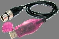
3 2D VIEW D VIEW OPERATING INSTRUCTIONS Building a scene GLOSSARY BEFORE YOU BEGIN What is Included 1 x USB to DMX cable, Box interface or Rack mount interface 1 x USB cord (Box interface and Rack mount interface only) 1 x power cord (Rack mount interface only) 1 x Software Installation CD-ROM Unpacking Instructions Immediately upon receiving the interface, carefully unpack the carton, check the contents to ensure that all parts are present, and have been received in good condition. Notify the shipper immediately and retain packing material for inspection if any parts appear damaged from shipping or the carton itself shows signs of mishandling. Save the carton and all packing materials. In the event that a fixture must be returned to the factory, it is important that the fixture be returned in the original factory box and packing. Do not plug in the USB interface before installing the software! AC Power This product receives its power from the USB input and does not require any external power supply as long as a computer is present. If the interface is needed to run without a computer, a 9-12VDC 300mA power adaptor (Box interface) is required (not included). If running the Box interface from a portable computer (notebook), an external power supply is recommended but not required. USB to DMX cable Box interface Rack mount interface CPU PRESENT STAND ALONE 2 ND UNIVERSE* CPU PRESENT 2 ND UNIVERSE* STAND ALONE Required n/a n/a n/a Power via USB. 9 12VDC power adaptor recommended Power via USB cable. (included) 9 12VDC power adaptor required. (not included) Power via power cord (included) Power via USB. 9 12VDC power adaptor recommended Power via USB cable. (included) 9 12VDC power adaptor required. (not included) Power via power cord (included) * Requires the purchase of an additional Box interface or Rack mount interface interface. 3

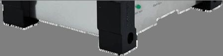
 Unlimited shows when using a computer Power selection switch USB connection DMX output 9-12VDC power supply input")
4 INTRODUCTION USB to DMX cable Features USB to DMX cable 10 fixtures with a maximum of 100 DMX channels Unlimited shows when using a computer 3D rendering only while interface is not connected DMX output Protective cap USB connection Box interface Features DMX-512 USB interface Connect 2 Box interfaces for 1024 DMX channels (2 universes) DMX input for on-the-fly, external override Selectable power options: USB or DC adaptor (not included) Playback 1 show without a computer (100 DMX channels max) Unlimited shows when using a computer Power selection switch USB connection DMX output 9-12VDC power supply input DMX input 4
5 Rack mount interface Features Rackmount DMX-512 USB interface Connect 2 Rack mount interface for 1024 DMX channels (2 universes) DMX input for on-the-fly, external override (works in stand-alone) Connector for external triggers Selectable power options: USB or AC (cable included) Playback up to 14 shows without a computer (with speed control and layering) Unlimited shows when using a computer Trigger scenes automatically without a computer 1-space (1U) rack mount Used for external triggering of light scenes Pin1 = button #1 Pin 16 = button #16 Pin 25 = ground USB connection Power supply input DMX input Power selection switch DMX output 5
 100MB of hard disk space 1 CD-ROM drive 1 USB port MINIMUM HARDWARE REQUIREMENTS (with 3D visualization) All requirements above ATI Radeon 7000 or")

6 SETUP CPU Requirements MINIMUM HARDWARE REQUIREMENTS (without 3D visualization) Pentium 1Ghz with 512MB RAM under Windows XP (32-bit only) Pentium 2Ghz with 1GB RAM under Windows Vista (32-bit only) 100MB of hard disk space 1 CD-ROM drive 1 USB port MINIMUM HARDWARE REQUIREMENTS (with 3D visualization) All requirements above ATI Radeon 7000 or NVIDIA GeForce2 (gobo viewing disabled) ATI Radeon 9000 or NVIDIA GeForce4 (maximum 3D rendering) Desktop colors set to 32 bits Software Installation (Windows Vista and XP) 1. Double-click the Software icon to initiate the software installation. 2. Click NEXT to continue. 3. On the License Agreement page, click I accept the agreement and then click NEXT. 6

7 4. Choose the installation directory to install Software. The proposed path usually does not need to be altered. 5. Select a name and location for Windows to place the Start Menu folder. 6. Check the box titled Create a desktop icon if you want a folder to be created on your desktop. This action cannot be undone so it may be better to create the folder and delete it later on. Click NEXT. 7. Confirm the settings and then click INSTALL. 7

8 8. After the installation completes, click FINISH to confirm. You must be logged in as Administrator to install the software. 8


9 Hardware Installation (Windows Vista) After the software is installed, it is time to connect the interface to the computer. Make sure the Software software is not running while attempting to connect the interface to the computer. To connect the interface, please follow the instructions below: These instructions do not account for the User Account Control security measure that Windows Vista has. Simply click CONTINUE if that window should appear during installation. 1. Close all Software windows 2. Plug the USB cable into the back of the interface and the other end into an available USB port on the computer. 3. A message will come up indicating that Windows needs to install a driver. Click Locate and install driver software and the computer will automatically search for the drivers that were installed during the software installation. This may take a few minutes to complete. 4. A message indicating that the publisher cannot be verified may pop up, simply click Install this driver software anyway to continue with the installation. 9
 After the software is installed, it is time to connect the interface to the computer.")

10 5. A message will appear indicating that the driver installation was successful and the stand alone LED will turn off (Box interface) and PC Link will turn on (Rack mount interface) indicating that a proper connection to the computer has been established. Hardware Installation (Windows XP) After the software is installed, it is time to connect the interface to the computer. Make sure the Software software is not running while attempting to connect the interface to the computer. To connect the interface, please follow the instructions below: A driver must be installed for each interface connected to the computer. 1. Close all Software windows 2. Plug the USB cable into the back of the interface and the other end into an available USB port on the computer. The Found New Hardware Wizard must be completed in order for the computer to communicate with the interface. 3. When Windows XP asks if it can connect to Windows Update to search for software select No, not this time and then click NEXT. 4. On the next screen, select the bubble that reads Install the software automatically (recommended) 10


11 5. Windows will then ask for a specific place to install the drivers from. Click BROWSE and direct the driver path to the C:\WINDOWS\system32\drivers folder and select the CyUsb driver. Click OPEN and then OK on the following screen to start the installation. Substitute the driver FTD2XX for CyUsb if connecting an USB to DMX cable. 6. When the following window appears prompting that the driver did not pass the Windows Logo testing compatibility, simply click CONTINUE ANYWAY to continue the installation. 7. When it s complete, click FINISH and the window will disappear and a popup will indicate that the driver installation was successful. 11

12 Driver Reinstallation (Windows Vista) If the driver installation fails or you need to reinstall the driver for any reason, the driver can be installed manually. Please follow the instructions below: 1. Click START > CONTROL PANEL > SYSTEM > DEVICE MANAGER to access the hardware devices on your computer. 2. Extend the Universal Serial Bus Controllers section by clicking on the small square to the left. 3. Highlight the BOX Interface (version x.xx) (or cable or rack mount interface) and select uninstall on the top menu bar. This will uninstall all associated drivers for the interface. 4. Click scan for hardware changes also on the top menu bar to have the computer auto-detect any new hard ware. 5. The computer will automatically scan and install the necessary drivers for this device. Driver Reinstallation (Windows XP) If the driver installation fails or you need to reinstall the driver for any reason, the driver can be installed manually. Please follow the instructions below: 1. Click START > CONTROL PANEL > SYSTEM > HARDWARE > DEVICE MANAGER to access the hardware devices on your computer. 2. Extend the Universal Serial Bus Controllers section by clicking on the small square to the left. 12

 to install the driver again. 6.")
13 3. Highlight the BOX Interface (version x.xx) (or cable or rack mount interface) and select uninstall on the top menu bar. This will uninstall all associated drivers for the interface. 4. Click scan for hardware changes also on the top menu bar to have the computer auto-detect any new hardware. 5. Repeat the same steps from Hardware Installation (Windows XP) to install the driver again. 6. A popup balloon in the lower, right side of the monitor will indicate that the driver installation was successful and the device is ready to use. 13

14 USING SOFTWARE Initial Parameters (Init_param) When the CONTROL_BOARD is opened for the first time, you must first select the operating language for the software and the manual. Simply click on the flag that corresponds to the desired language. This can be changed later for multilingual users. Close the INIT_PARAM window and re-open the CONTROL_BOARD. This time it will open in the language that was just selected, and will also read USB box interface ok. (Please substitute the interface name if an Rack mount interface or USB to DMX cable is connected.) If there are multiple interfaces connected such as two Box interface or two Rack mount interface, the line of text will be doubled. (Two USB to DMX cable interfaces cannot be used for two-universe support. If opting to use multiple universes such as two Box interface interfaces, both units must have the same firmware version. 14

15 CONTROL BOARD Every screen (except Stand Alone) is initialized from the CONTROL_BOARD and it must also be running in the background in order to correctly send and receive DMX signals. It will display the installed software version and it will also list any connected interfaces on separate lines. Since this is the software s main point of access, it cannot be minimized to the task bar or maximized to fill the entire screen. You can, however, drag and drop it to a secondary monitor. In order from left to right, these are the windows accessible from the CONTROL_BOARD: 1. INIT_PARAM sets the language that the software will operate in 2. BACKUP exports the entire show (except multimedia files) 3. RESTORE restores an entire show or a portion of one 4. FIXTURE setup a show. Includes DMX addressing, individual channel assignments, DMX values and creating new fixtures 5. BUILDER easily program steps, scenes and shows 6. GENERATOR generate new and edit existing macros with variable fanning effects 7. LIVE user-configurable playback window (with layering) 8. TIMELINE synchronized multimedia creator with lighting, audio and video 9. DMX INPUT patch any DMX channel to an external controller 10. 2D VIEW manage the fixtures in a 2D environment 11. 3D VIEW see and control a complete show in real-time from any point of view 12. Manual opens this manual in PDF format 13. Support opens the Software forum (must have an active Internet connection) shows a visual of the DMX output 15. Exit closes the CONTROL_BOARD window 15
 of each DMX channel.")
16 FIXTURE The FIXTURE screen is the window that assigns DMX addresses to the fixtures of a show, creates and edits new and existing fixture profiles, assigns group letters and 3D settings, and finally sets the level (or value) of each DMX channel. List of fixtures in the main library 3D View attributes Channel attributes Level or value attributes List of personal fixtures DMX addressing, fixture renaming and grouping Buttons to edit the levels or values Buttons to edit the channels 16
17 Here is a list of the buttons within this screen and their function. BUTTONS DESCRIPTION Closes the screen. Creates an empty workspace for a new, custom fixture. 1) Saves a custom fixture s settings and moves it to the Personal Fixtures window. 2) Drops a fixture from the Personal Fixtures to the DMX Addressing window. 1) Adds channels to a new, custom fixture under the CHANNELS column. 2) Adds values to specific channels under the LEVELs column. Deletes a fixture from the Personal Fixtures and removes the TXT file from the hard disk. 1) Removes a fixture from the DMX addressing window. 2) Removes a DMX channel from the channel column. 3) Removes a group of values from the levels column. Copies a DMX channel to another DMX channel. This will work for two channels within the same fixture or even from one fixture to another. Pastes a DMX channel to another DMX channel. This will work for two channels within the same fixture or even from one fixture to another. 1) Inserts a channel above the highlighted channel when in the channel column. 2) Inserts a set of values above the highlighted trait when in the level column. To add fixtures to the show, start at the top left and work down. Choose the manufacturer of the fixture by double-clicking on their name. The software will then expand and list all available profiles for that manufacturer. Since this is a master list, fixtures must be added individually to the Personal Fixtures in order to work with them. 17
18 Creating New Fixtures 1. Click the icon to make a clean working space for the new fixture. 2. Type a name for the fixture where it says NEW_FIXTURE 3. Define its 3D properties by choosing whether it is a moving yoke, moving yoke wash, mirror, etc. Once that has been chosen, other options may become available. Enter the required information for the new fixture. 4. Click the icon for each channel of DMX that the fixture requires. For example, if it is a 5-channel scanner, click the icon five times. This information can be found in the product s user manual. 5. From the pull down menu under the channels column, select the functions for each one of the channels. For example, if channel 1 is the color wheel, select color. Use the chart above to manipulate the channels as needed. 6. Each of the channels must be defined in order to use Software to its fullest. To define each of the channels, highlight the channel and click the add its values for each of its DMX channels. icon to 7. Click the flashing to save the fixture and it to the Personal Fixtures. This information can be found in the product s user manual. If a profile for a specific fixture is not included in the Main Library, please contact Chauvet s customer service department and one can be created. Edit Existing Fixtures If there is a fixture that needs to be updated for any reason, simply follow the instructions above to add it to the Personal Fixtures, highlight it and use the options from the 3D View, Channel and Level columns to edit as many fixtures as needed. Edited fixtures will be saved in the Personal Fixtures until they are deleted, and will not be permanently saved to the Main Library 18

19 DMX Addressing Procedures The fixtures in the DMX addressing window are the fixtures that are going to be used in a show. When they are added from the Personal Fixtures they will automatically be given a DMX address based on the quantity of channels used by the fixture before it. These DMX addresses may be manually adjusted as needed. When no fixtures are present in the DMX addressing window, it will automatically start the first fixture at DMX address of 001. If a fixture is added to the DMX addressing window after other fixtures, it will automatically be given an address immediately after the one that proceeds it; the software will never skip channels. To set the fixtures that will be in a specific show, double-click their names in the Personal Fixtures window to add them to the DMX addressing window. If multiple, identical fixtures are needed, double-click the amount of times to add it. For example, if four COLORado 3 s are needed, double-click the fixture four times. To further explain the DMX addressing window, please see the chart below. Check this box to address on the 2 nd universe. Two fixtures having the same address is possible when using 2 universes. The fixture on the 1 st universe would have an address of 007, and +007 for the 2 nd. Check these boxes to reverse the pan & tilt movements. Use this text box to manually enter a DMX starting address. Use this text box to manually enter the number of fixtures to show in 3D View. The default number is 1. Use this text box to manually enter fixture names. Displays the binary addressing for a fixture with dip switches. In this example, switches #1,2,4,5 are on and #3,6 9 are off. Use this text box to manually enter fixture groups. Each fixture can be a part of 5 different groups to help with programming. 19
 Before immediately diving into the software, understanding the lingo will drastically save time when trying to program for the first time.")
20 BUILDER The BUILDER screen is the window that allows for fixture programming, editing steps and step time, saving light scenes, and activating some built-in movement macros. (Just to name a few!) Before immediately diving into the software, understanding the lingo will drastically save time when trying to program for the first time. Opposite of a lot of physical DMX controllers, Software uses the same terminology but in a different way. For example, a step is a static look of a scene and a combination of steps is considered a scene. (A scene may also consist of a single step. ) Multiple scenes are considered a show and when using a computer there are an unlimited number of shows, scenes, and steps that can be created. Let your imagination run wild! Step area Scene area Display window Misc area Override area DMX channels area Mouse area 20

21 Step Area The step area shows the number of total steps in a specific light scene, the duration of the entire show and of a specific step, and allows for editing of existing steps and creating new ones. STEP AREA BUTTONS DESCRIPTION Displayed when a step cannot be deleted. Only occurs when there is a single step in any scene. Copies any step and puts it into the computer s memory. Pastes a copied step in front of the one that is currently showing. Adds a step to the current scene. Inserts a step after the selected step. Displays the name of the current step. This can be renamed to anything you want by typing in the text box. Displays the length of time the step will take to move to the next one. Displays the length of time the entire scene occupies. 21
 1) Allows to manually enter a name for a new scene or rename a previously recorded scene.")
22 Scene Area The scene area gives access to all programmed scenes, typing names to new scenes, inserting scenes into each other, saving scenes and deleting them as well. SCENE AREA BUTTONS DESCRIPTION Plays the current scene. (All other functions will be disabled until stopped.) 1) Allows to manually enter a name for a new scene or rename a previously recorded scene. 2) Gives access to all previously recorded scenes. Creates a new, empty scene. Opens a previously recorded scene and closes the one that is currently open. When a scene is open, click the pull down menu to access another scene and then click this icon to merge the two scenes together. The second scene will be merged before the last step of the first scene. Saves the scene that is currently being programmed. Each time a change is made, this icon will flash red and yellow to remind the programmer to save their work. Deletes the light scene that is currently open. (This is a permanent action and cannot be reversed.) Play/stop the opened scene Type names of new scenes and open existing ones Deletes the current scene Starts a new scene Saves the current scene Opened a saved scene Insert a scene into another one 22

23 Mouse Area The mouse area displays the position of the mouse coordinates using both DMX values (0 255) and percentages (0 100%) and scrolls through all fixtures using the arrows on the sides. Scroll the visible channels to the left Shows the percentage of the pan and tilt. Shows the DMX values of the pan and tilt. Scroll the visible channels to the right. 23
24 Miscellaneous Area The miscellaneous area activates the 2D View, 3D View, activates or terminates the DMX signal coming from the computer, allows to undo a mistake and activates the mask feature. MISC. AREA DESCRIPTION BUTTONS This is a scene that can only contain a single step and is designed to be added over the current scene playing back. Program a scene called mask and move the pan, tilt and dimmer to any position where it becomes visible so when this MASK scene is activated, the light will move to a specific position and the shutter will open. This way the colors, gobos and other effects can be seen. Click this icon to undo the last action. Turns the DMX signal on and off. Opens the 3D View. Opens the 2D View. The undo feature will only undo the last mouse click and will not restore a scene that was just deleted! Activates the MASK feature Activates the 2D View for groupingon the fly Undo the last mouse click Activate the 3D View to see the lights in real time Activates the DMX signal from the interface 24
25 Override Area The override area allows for additional control of a single channel or multiple channels. Time-saving icons include set value on all steps, set fade on all steps, copy and paste functionality and cut (not delete). OVERRIDE AREA BUTTONS DESCRIPTION Deactivates a channel from a specific step and sets its value to OFF, not 000. This will prevent accidental overriding when using the LIVE screen. Copies a channel s value and puts it into memory. Use the standard Windows shortcut keys such as CTRL and/or SHIFT to select multiple channels. Pastes the value from memory onto the desired channel or channels. Use the standard Windows shortcut keys such as CTRL and/or SHIFT to select multiple channels. Double click this icon to paste values on all steps within the same scene. Sets the fade style on specific channels to all steps of a particular scene. Use the standard Windows shortcut keys such as CTRL and/or SHIFT to select multiple channels. Sets the value on specific channels to all steps of a particular scene. Use the standard Windows shortcut keys such as CTRL and/or SHIFT to select multiple channels. Deactivates a channel from the step Sets all values of the selected channel to the same for all steps within the scene Copies the channel value into memory Changes the way steps go from one to the other to all the steps within the scene Pastes the channel value from memory 25
26 DMX Channels Area The DMX channels area provides the way to control all fixtures connected to the interface using a series of sliders. The icons above the channels are the same ones that are in the FIXTURE screen and offer an easy way to select multiple channels for simultaneous programming. The names and group letters are also displayed along with the DMX channel under each fader. There are many parts of the DMX channels area that when combined together create a very powerful light-programming tool. The term channel in the BUILDER screen consists of an icon, slider and DMX channel number. Displays the icon for a specific channel. (Color wheel shown.) Right click the icon to see all possible settings. Allows manual control of each channel separately. Move the slider up to increase the value or down to decrease it. Values range from 000 to 255. FADE STYLE BUTTONS DESCRIPTION The current step will snap into the next step. Displays the DMX channel number or the fade style. The current step will fade into the next step. Adjust the time in the step area to create a slow, smooth fade. The current step will rotate in a circular, clockwise movement into the next step. Will be replaced with the Bezier curve in future releases of the software. The current step will rotate in a circular, counter clock wise movement into the next step. Will be replaced with the Bezier curve in future releases of the software. Uses the Bezier curve style which is created from the GENERATOR screen. Left click to change the fade style 26
27 Activated vs Non-Activated Faders There is a big difference in how scenes are played back based on if a specific channel has been activated or not. Non-activated faders will show a DMX channel beneath the slider (example below shows 13). Once the fader becomes activated, it will show one of the fade styles. When multiple scenes are played back in the LIVE screen, it layers (or stacks) the scenes on top of another and the last scene to be triggered will take priority. This may cause unwanted behavior of the fixtures and should be the first place to check if something turns off when it wasn t supposed to. To deactivate a fader, simply click the icon so a red check mark appears, and click the scissors in the Override area. Non activated Activated 27
, right-click it to access a hidden menu that allows to load, save or reverse movements, shift movement one step forward or")
28 Right-Clicking There are a few additional menus that become accessible when clicking with the right mouse button. The list below explains how to access these hidden menus and what their functions are. 1. When the icon above the channel slider is an X or Y (pan or tilt), right-click it to access a hidden menu that allows to load, save or reverse movements, shift movement one step forward or backward and it enables the F4 key to resize the movement. FUNCTION DESCRIPTION Load Movement Enters the movement macro window and allows to load pre determined sets of pan/tilt to create unique shapes with the movement. Save Movement Reverse Movement Shift Forward Shift Backward F4 (Resize) Saves a scene the programmer created to the library of other movement macros for future use. Changes the last step into the first, second to last into the second, etc. Shifts step 1 to 2, 2 to 3, 3 to 4, 4 to 5 and the last step to the first step. Step 1 becomes the last step, 2 becomes 1, 3 becomes 2, 4 becomes 3, etc. Changes the display to allow for easily resizing the movement of a particular scene. Please see page 29 for further information about this part. 28


29 2. When the icon above the channel slider is a color or gobo wheel, rightclick it to access all of the color and gobo possibilities of that particular fixture. Simply click the color or gobo and the light fixture will instantly jump to it. 29
30 Display Window The display window has a few different functions depending on the fixtures that are being used. 1. When the fixture has pan and/or tilt channels, programming on a 2D drawing board can be accomplished simply by clicking the fader that corresponds to the pan and/or tilt. This will also give access to the function keys which allow the programmer to change the look of the drawing board to something different. Please read below for more details about the function keys. FUNCTION KEYS DESCRIPTION F1 Opens the manual in HTML format. This can be pressed at any time while the software is running. F2 F3 F4 Displays a grid for beam targeting type effects. Use this grid as a scaled model of a dance floor or a wall to help with positioning of moving fixtures. Press F2 a few times to change the scale of the grid. Displays a single step of the light scene or the entire scene. This tool is useful in seeing where the fixture came from and where it is going next. Allows to resize the current step of the scene. Click and drag the pink box that shows up to resize the step. F5 Switch between icon mode and value/percentage mode for all icons above all channels. 30

31 2. When the icon above the channel slider changes to look like this icon, it means that channel can now controlled by using the color mixing palette. Displays the actual color emitted from the RGB color mixing fixture. Copies the selected panel color to memory. Pastes memorized color from memory. Move the mouse over this area to select the color. Adjusts the brightness of the output. To use the color palette, simply click and drag the mouse over the spectrum of colors on the bottom and the selected RGB fixtures will change instantly to the color that was selected. The brightness can be controlled by the slider on the right and the RGB values can be copied and pasted to other fixtures quickly and easily. This feature will also work with a CMY color mixing system. Using this palette does not affect any other channels except red, green and blue (or cyan, magenta and yellow). 31
32 GENERATOR This window contains some of the newest technology in the lighting controller market and allows the programmer to quickly and easily generate movement and basic curve macros with delay effects in a matter of seconds. This technology is seen in larger concert-style control desks and is also available in Software. There are two different functions of the GENERATOR window. The first is a movement macro creator which incorporates only the pan and tilt channels for all moving head and scanners. In this mode the horizontal axis represents pan (from ) and the vertical axis represents the tilt (from ). The second function of the window is to generate basic curve effects using all other channels. In this setting, the horizontal axis converts to the time and the vertical axis represents the level, or DMX value from GENERATOR BUTTONS DESCRIPTION 1) Creates a new, blank curve to generate effects. 2) Creates a new project. 1) Opens an existing curve that was previously saved. 2) Loads a saved project. 1) Saves the curve and stores it for later use. 2) Saves the project and stores it for later use. Activates (plays) the current file and sends data to the fixtures. Pauses the playback and the fixtures will stop exactly where they are. Stops playback and resets all fixtures to 000. Activates the DMX output. This must be on for the PLAY button to work correctly. Sends the data to be seen within the 3D View screen. Saves (generates) all settings and creates a scene file (.SCE) to be recalled in the BUILDER window. Locks and unlocks the selected channels on the left side. 32

33 Creating Movement Macros To create movement macros with delay effects, please follow these steps: 1. Click GENERATOR on the CONTROL_BOARD to open the window. 2. Open the BUILDER screen also from the CONTROL_BOARD and select the group of fixtures you wish to make a movement macro with. 3. That group now shows up in the GENERATOR window and lists the group letter and the quantity of fixtures within it. (This example selected group d and it contains 2 fixtures. The list of channels below the group and quantity shows the channels that the selected fixtures have in common. 4. Select the check box next to Pan/Tilt/uPan/uTilt. The single check box will take into account all fixtures within the same group. 5. Create a new movement by moving the red points around the workspace until the desired effect is reached. If you do not want to create one from scratch, click the OPEN icon to the right of the duration and select any from the list. Drag and drop these red dots to adjust the values. Right click any dot to access additional functions and features. Right click anywhere to access additional functions and features. The white dots represent the location of the fixture. 33
34 These can also be opened, edited and resaved for future use. Placing the mouse over a red dot will display the pan (first number) and the tilt (second number) of that specific point. 6. Click the PLAY icon to start the playback and then click the DMX icon to send the data through the interface to the fixtures. The selected fixtures will now begin moving based on the movement and speed that was entered. 7. Adjust the amount of time for the entire scene to play back (in seconds) by entering the desired length of time into the text box titled DURATION. 8. Slide the FAN slider on the bottom to adjust the delay between each fixture. The greater the number, the greater the distance between the first and last fixture. A fan setting of 0 will result in all fixtures moving to the exact same spot at the exact same time with no delay. 9. Click the GENERATE icon to save the movement as a scene (.SCE). This file is immediately ready for editing in the BUILDER window. 10. Open the new scene from BUILDER, make any changes or additions (such as shutter color, gobo) and save again. The scene is now complete. 34

35 Creating Curves To create basic curves with delay, please follow these steps: 1. Click GENERATOR on the CONTROL_BOARD to open the window. 2. Open the BUILDER screen also from the CONTROL_BOARD and select the group of fixtures you wish to make a movement macro with. 3. That group now shows up in the GENERATOR window and lists the group letter and the quantity of fixtures within it. (This example selected group d and it contains 2 fixtures. The list of channels below the group and quantity shows the channels that the selected fixtures have in common. 4. Select the check box next to the channel(s) you wish to create the curve for. 1. Multiple channels can be selected simultaneously such as color and dimmer to program at the same time. 5. Create a new curve by moving the red points around the workspace until the desired effect is reached. If you do not want to create one from scratch, click the OPEN icon to the right of the duration and select any from the list. 6. Click the PLAY icon to start the playback and then click the DMX icon to send the data through the interface to the fixtures. The selected fixtures will now begin moving based on the movement and speed that was entered. 7. Adjust the amount of time for the entire scene to play back (in seconds) by entering the desired length of time into the text box titled DURATION. 8. Slide the FAN slider on the bottom to adjust the delay between each fixture. The greater the number, the greater the distance between the first and last fixture. 35
36 A fan setting of 0 will result in all fixtures moving to the exact same spot at the exact same time with no delay. 9. Click the GENERATE icon to save the curve as a scene (.SCE). This file is immediately ready for editing in the BUILDER window. 10. Open the new scene from BUILDER, make any changes or additions (such as movement) and save again. The scene is now complete. The curve style (points, lines or curves) changes the display to reflect how the movements and curves are seen. 1. Points displays only the points of a particular movement or curve 2. Lines displays the movements of the fixtures (yellow lines) without any curves and will adjust the fixtures accordingly. 3. Curves displays the movement of the fixtures (yellow lines) with all curved settings. (This is the default.) 36

37 Example This example demonstrates what the screens should look like when creating a scene with pan/tilt movements, color chasing and keeping the shutter/dimmer open throughout the entire scene. This first step shows that the pan, tilt, color, dimmer and shutter are all selected to be a part of the scene. When the channel is highlighted in blue (pan/tilt), the window to the right will change to reference its steps within the scene. Each of the red dots indicates a movement step. You can follow the path of the scanner or moving yoke by looking at the numbers next to each step. These dots can also be dragged around to any location and the lights will move in real time. The second image shows the color wheel s position. Place the mouse over the red dots to see its value. Right-click the mouse to access a menu that will allow to edit the points. 37
38 This third and fourth image show the level (or value) of the dimmer and shutter. Right-click on any dot to access another menu which will allow to edit the points. Changing Groups To change the fixture group that you are working with, please follow the steps below: 1. Click the padlock icon to unlock the window. 2. Go back to the BUILDER screen and select another keyboard group or select the fixtures on the fly by using the 2D VIEW. 3. The group letter and fixture quantity will change based on the new group. 4. Repeat the steps from Creating Movement Macros or Creating Curves to program an effect. 38

39 TIMELINE TIMELINE allows the programmer to create shows by synchronizing lighting, audio, video and still pictures together by using drag and drop technology. The LIVE screen must be open for TIMELINE to playback correctly. The Light scenes window displays a list of all scenes created from the BUILDER screen. These scenes are ready to be dragged into a new or saved timeline file. The Multimedia files list shows all imported sound, video and still images that are a part of the show. The accepted file formats are as follows: 1. Audio wav, mp3, ogg, wma 2. Video avi, mpg, mpeg, mov, wma 3. Still images bmp, gif, jpg, png Shows a list of all multimedia files that are loaded and ready for use Lists all light scenes created in BUILDER and/or GENERATOR Control buttons of the open timeline file Stops the playback of any timeline (video, audio or lighting) 39
 of the multimedia fileson your computer. 2.")
40 Adding Multimedia Files To add multimedia files to the list, please follow the directions below: 1. Click the import multimedia files icon directly under the Multimedia files heading. Import multimedia files Remove multimedia files Shows the full path (location) of the multimedia fileson your computer. 2. Direct Software to the location of the audio, video and/or image files and click OPEN. Repeat this process as much as necessary. These files will available until the current project is closed. Make sure to save your work! Keyboard & Mouse Operation Using the keyboard and mouse to navigate within TIMELINE can help align scenes to the exact position you are trying to reach and enable you to do multiple things simultaneously. The keyboard s functions are: 1. Space bar alternates between play and stop 2. Enter plays the timeline from the red marker 3. Home/End go to the beginning or end 4. +/- zoom in and out 5. Left/right arrow moves the green marker 6. Shift + left/right arrow moves the red marker The mouse s functions are: 1. Scroll wheel zoom 2. Press scroll wheel move 3. Double click the digital timeline sets the red marker 40

41 Creating a Timeline To create a new timeline from scratch, please follow the directions below: 1. Click TIMELINE on the CONTROL_BOARD to open the window. 2. Click to start with a fresh palette. 3. Enter the amount of time for the timeline and type it in the text box where it says Timeline duration. 4. Enter the amount of lighting timelines to have within the file from 1 to 10. This can be changed at any time. 5. Click OK to save the settings of the new timeline. Enter the maximum time Check this box to add an additional timeline which will allow to place labels (similar to Post It notes) within that timeline Enter the amount of lighting timelines 6. Add any necessary multimedia files to the current show by following the instructions in Adding Multimedia Files above. 7. Click and drag the multimedia file(s) to their respective rows and drag them to your desired starting point. 8. Add light scenes by clicking the desired scene and dragging it onto any of the Light timeline rows. The amount of Light timelines can be adjusted by going to the EDIT menu and selecting the PROPERTIES option. Use the tool to stop the playback of any multimedia file. 9. Click to ensure the show is what was desired, and then click to save your work. To delete any scene, right-click it and select DELETE. 41


42 Digital timeline used to sync files to each other. Set the red dot to any spot within the timeline to automatically start playback when the is clicked. The green dot shows the location that is currently playing back. Click and drag this marker to start the playback from any point. Video file Audio file Light scenes Displays the name of the current timeline file Displays the time of the timeline in hr : min : sec Moves the green marker to the last file in the timeline Moves the green marker to the beginning Plays back the timeline from the red marker Stops the playback Plays back the timeline from the green marker 42

43 LIVE LIVE screen is the application that plays back the pre-programmed light scenes by layering them. Please refer to the glossary for a definition of layering. LIVE is designed to use in a live situation where the software will be manned throughout the entire show. Menu bar Play/Pause Page tab Scene board Freezes the playback 43
44 There are a few buttons that can be found within the LIVE screen. These buttons are: LIVE BUTTONS DESCRIPTION This sets the board to allow you to select the next scenes you want by deactivating the button without actually deactivating the scene. While scenes are playing back, click this button and then click the scenes that are currently playing and then click scenes that you want to playback next. When this button is clicked for a second time, it will switch the scenes that are currently playing to the ones that are not. Tap this button to the beat of the music to manually set the BPM of the light scene. Activates the 3D View to watch the show in real time Activates the DMX output. This must be on (green) in order to successfully run a show. Please see the administrator options to automatically activate the DMX when LIVE is opened. Click this button to immediately pause (freeze) playback. MIDI Indicated whether a MIDI interface is linked to the computer Timeline Indicates whether LIVE is receiving the order to play scenes from the TIMELINE window Right-click any tab to access a menu which will allow you to: 1. Add a page adds a page to the top to help organize scenes 2. Rename page renames any tab 3. Move page moves a page left or right 4. Remove a page deletes a page and all of the scenes within it 5. Add a light scene adds 1 or more light scenes to the current page 6. Add a timeline file adds 1 or more timeline files to the current page 7. Add a multimedia file adds 1 or more audio, video or picture files to the page 8. Solo out a scene sets all scenes within that page to only allow 1 to play back at any given time. This option will not allow for layering. 9. Chase play - plays back a scene and then the scene directly below it. When that column of scenes has completed its playback, it will automatically trigger the next column and continue to playback the scenes in order. Multiple starting points are acceptable. 10. Random play selects scenes within the same page at random to play back. The user must trigger the first scene and the computer will take over after. 44
45 Right-click any scene to access a menu which will allow you to: 1. Move a button moves a scene within the page. 2. Remove a button deletes that scene from the page 3. Color a button adds a background color to the scene 4. Speed button sets the scene to playback via automatic beats per minute (BPM), manual BPM, or manual speed 5. Trigger button opens a secondary window which allows you to set the scene to trigger via a keyboard letter, a specific date and time, MIDI, or an external DMX controller 6. No loop button sets a specific scene to stop after playing back instead of looping 7. Flash button sets a specific scene to be triggered only when the mouse button is holding the scene down 8. Preset button sets the scene to be able to scroll through each individual step within that scene. This is primarily used for scenes that contain RGB or CMY color mixing fixtures. In addition to these options, clicking on the menu bar at the top will offer many additional options and settings for the LIVE window. These options and descriptions are listed below: Menu Option Sub-Function Description Boards Display Administrator Options Help 1 Displays a single board on which to load light scenes into for playback. 2 Displays 2 boards on which to load light scenes into for playback. 4 Displays 4 boards on which to load light scenes into for playback. Keyboard trigger Displays the keyboard letters that are currently set to activate a scene Calendar trigger Displays the time in hours, minutes, and seconds MIDI trigger Displays the MIDI key that a particular scene is set to be triggered by DMX trigger Displays the external DMX command that a scene is set to be triggered by Displays whether a scene is set to be triggered by automatic Speed info beats per minute, manual beats per minute, or manual speed (default) Maximize screen at launch Maximizes the screen when it is opened from the CONTROL_BOARD Disable screen resizing Disables the ability to resize the LIVE window Allow to shutdown computer Allows the user to shut down the computer DMX on at launch Automatically activates the DMX signal when LIVE is opened. (indicated by the DMX icon on the right side) MIDI note on velocity? Lock screen (button) When activated, prevents changing settings by right-clicking Use password Uses a password to unlock the lock screen setting Opens this manual in PDF form 45
46 Adding a Scene 1. Right-click on the top of the page (in the tab area) that you wish to add a file to and select the appropriate option. To add a light scene, click add light scene, to add a Timeline file click add Timeline, and to add an audio, video or still image click add multimedia. 2. Direct the software to the file s location and click OPEN. Multiple files may be added simultaneously by using a combination of the CTRL and SHIFT keys. Follow the same steps to add scenes, timelines or multimedia files. Right-click menus are only available on the first board. Playing Back Scenes 1. Activate the DMX output by clicking the icon. 2. Click on the scene you wish to play back (unlimited scenes may be played back simultaneously) and the scene will change colors to a darker shade of grey indicating that it is active. Right-click any scene to access additional scene options which will manipulate the scene to help achieve the desired look. An explanation of these options is on the previous page. 2D VIEW This window allows for grouping on the fly by using a 2D environment. Much like pressing a letter on the keyboard to activate a group of fixtures, the 2D allows to manually select each fixture (or fixtures) and will automatically trigger them in the BUILDER or GENERATOR windows for programming. The 2D View can be resized at any time by clicking the corners and/or sides and dragging to the desired size. To set up the window, simply click and drag each fixture to their respective locations so each one can be identified quickly and easily. To further help with fixture location and identification, you can change the background image to mimic the actual surroundings of the fixtures. For example, if the lighting is suspended in a nightclub ceiling, a picture of the actual ceiling may be taken and imported in to the 2D View. The icons of each fixture can then be placed over the real ones to help identify them. 46
47 Importing a Picture 1. Take a picture of the desired location and import that picture to your computer using any method you are familiar with. Make sure to store this picture in a location you will remember. 2. Right-click anywhere in the 2D VIEW and select CHANGE BACKGROUND. 3. Point the software to the location of an image you wish to import and click OPEN. You can also change the picture of the fixture by right-clicking the actual fixture and choosing change fixture picture. It is also possible to import your own fixture drawings; please refer to the online forum for more details. Selecting /Deselecting Fixtures Fixtures can be selected by double-clicking the icon that represents each fixture. A fixture is selected when there is a red box around it. There is no limit to how many fixtures can be selected simultaneously. To select multiple fixtures, double-click each fixture while holding down the CTRL key on the keyboard. To deselect a specific fixture double while others remain selected, hold CTRL while double-clicking each fixture you wish to remove. Additional Options 1. Change fixture picture changes the picture of the fixture to any other PNG file 2. Picture size adjusts the size of the fixture icons to normal, half or one-third their normal size. This will allow more icons to fit within the 2D VIEW. 3. Change background this allows to change the background picture. Accepted formats include JGP, BMP, JPEG and PNG 4. Lock fixtures this locks all icons and prevents them from moving around the screen. 5. Show hidden fixtures shows the fixtures that are hidden in 2D VIEW 6. Window always on top sets the 2D VIEW to always remain on top of all other windows, even when other windows are selected. 7. Help opens this portion of the manual. 8. About displays a popup indicating what version of the 2D VIEW is currently running. 47

48 SCREEN CONTROL This window will remain dormant on the computer until a multimedia file is played back from either LIVE or TIMELINE. SCREEN CONTROL is the same as Windows Media Player, itunes or any other multimedia playback program, and even uses the same codecs as these third-party programs. To activate SCREEN CONTROL, a multimedia file must be played in either LIVE or TIMELINE first, and then the icon will appear. You can access SCREEN CONTROL from the taskbar (lower-right corner where the clock is) and with a simple click of the mouse, the following options are presented: 1. Properties please see chart below for detailed description 2. Play file will open a dialog box in which you can select a single multimedia file to play back. These file formats can be either JGP, BMP, JPEG, PNG, GIF, WAV, MP3, OGG, WMA, AVI, MPG, MPEG, MOV, or WMA 3. Show on screen opens the window on top of all other windows 4. Show on DMX matrix this becomes available when matrix capture is enabled, and it shows the pixel mapping information that is sent to CONTROL_BOARD. The image below shows an example. l\ 48
49 5. Stop immediately stops the playback of the selected multimedia file but does not close the window 6. Exit closes the window and removes the icon from the taskbar Menu Option Sub-Function Description Video output Matrix capture Screen Display No border Always on top Force position Screen mode Enable matrix capture Matrix width (pixel) Matrix height (pixel) Original size Full screen Fixed size Preserve aspect ratio Centered Removes the Windows border and prevents you from accidentally closing or minimizing the window Keeps SCREEN CONTROL on top of all other windows Forces the window to a fixed position within the monitor s resolution Will output the multimedia files to a secondary monitor. Selecting this option will allow you to choose which display adaptor to send the files to Converts the video pixel mapping and sends the data streaming to CONTROL_BOARD Sends the size of the matrix being transmitted to CONTROL_BOARD Displays video files in their original resolution Displays video files at the maximum resolution supported by the connected monitor (This may make some videos appear blurry) Displays video files in a fixed, user-defined size Saves the resolution ratios of video files so increasing the video s output stretching will not occur Puts the video in the center of SCREEN CONTROL window 49

50 3D VIEW This window shows a representation of a show in three dimensions. It incorporates most aspects of any environment including people, truss, speakers, lighting fixtures and stages. Each object can later be manipulated and placed anywhere within the window to copy any setting or to create a new one. Once the 3D View is set up and everything is in the proper place, programming can be done offsite and still be able to see if the show is going to look good. To print the 3D view, simply right-click and click PRINT to immediately send the current view to a printer of your choice. To export the current view to the 2D View, right-click anywhere in the 3D View window and click EXPORT AS 2D VIEW BACKGROUND to immediately set the background image in the 2D View as this one. Navigating in 3D In 3D View, both mouse buttons (and even the scroll wheel) play equal parts in maneuvering throughout the window. When clicked and held, the left mouse button will change the orientation (or view) of the window. You can move left, right and even up and down. Press and hold the SHIFT key to adjust the pivot point of the orientation. Scroll the mouse wheel to zoom in and out of the window from any angle. Pressing the mouse wheel and then moving the mouse is the same as left-clicking while holding the SHIFT key to change the pivot point. (Same concept as the paragraph above.) The right mouse button gives access to the 3D menu settings which allow to edit fixtures, 3D settings, etc. 50

51 Stage Settings The Stage settings allows editing all aspects of the stage including dimensions, brightness, textures of walls, floor and ceiling, etc. Set the unit of measurement to either meters or feet Type in the exact numbers for the width, height and depth of the 3D View Adjust the overall brightness of the 3D View Check the boxes to the walls you want to show. If the box is not checked, the wall will not appear in the 3D View Import your own image and set it as the ground, walls or ceiling or use the textures that are built in 51

52 Object Settings The Object settings allows adding and editing objects within the 3D View such as the position, orientation, scale and color. By selecting the objects in the 3D View and then using the mouse, the objects can be moved around freely without having to slide the faders listed below. 1. Position allows to move an object on its X, Y and Z axis by sliding the three bars on the bottom of the window 2. Orientation allows to pivot an object on its X, Y, and Z axis by sliding the three bars on the bottom 3. Scale allows to enlarge or shrink any object using an XYZ format (length, width, depth) 4. Color allows changing the color of any object using RGB color mixing. Click the color palette in the lower right to access preset colors Click an object from the left list and a preview of it will show here Select an object from the list on the right and click the scissors to remove it Displays a list of all objects on stage Undo a single mouse click Exits the Object setting menu Type a number in the text field to 52 instantly jump to that setting or position Click POSITION, ORIENTATION, SCALE or COLOR and then slide these bars to make adjustments

53 Fixture Settings The Fixture settings allows editing the fixtures within the show such as the position, orientation, scale and color. Much like the Object settings, the Fixture settings allows editing and manipulating each fixture individually. Select the fixtures you wish to edit from this list Undo a single mouse click Exits the Object setting menu Type a number in the text field to instantly jump to that setting or position Slide these bars to adjust the position, orientation, scale and color 53

54 3D Settings The 3D Settings allows editing all aspects relating to the 3D performance of the window. Beam resolution and rendering, frames per second and auto rotation can be changed from this menu Changes the beam resolution from low to medium or high Switches between a computergenerated light beam and one that has more definition and structure Check this box to show the FPS and faces counter in the upper, left corner of the 3D window Adjusts the intensity of the light beams Adjusts the length of the beams coming from the fixtures Check this box to allow the software to auto rotate after a specific time frame. Enter the number (in seconds) to the right. Check this box to keep the 3D View on top of all other windows Use this text box to manually enter the frames per second for the 3D rendering Click this button to have the software run a quick test to check the maximum frames per second that the graphics card can handle 54
, the faders will be able to override the settings of the show that is playing back.")
55 DMX INPUT DMX INPUT connects the interface (Box interface or Rack mount interface only) to an external controller. When connected to an external controller and correctly patched (see glossary for definition), the faders will be able to override the settings of the show that is playing back. This is very useful because it allows the playback operator to manually alter the show without changing the actual programming. The Box interface interface must be connected to a computer in order to link with an external controller. When the Box interface and Rack mount interface interfaces are connected to the PC, the DMX INPUT window will manage the first 48 channels inputted. When the interfaces are in stand-alone mode, they will only manage the first 24 channels and they will always be set to OVE as the others are not managed. Before patching the faders to the DMX channels, it is important to know what the four different settings are for. Each fader can have only one setting, and if any of these are selected, the fader is considered active. The only way to deactivate a fader is to set it to OFF. 1. NOT stands for not overridden and will allow a signal to be sent and received when one is not being sent from the LIVE screen. 2. OVE stands for override and will override any signal(s) sent from the controller to the patched channels. This option will always leave the fader in control once activated. 3. HTP stands for highest takes priority and will only send a signal if the DMX value is higher than the one being sent from the LIVE screen. 4. LTP stands for last takes priority and only concerns the LIVE and DMX INPUT screens. Whichever window sends the latest information the fixtures will respond to it. Click the pull down menu to change the way the fader is controlled Lists the fader number from 1 to 48 Shows the channels that are patched to the external controller. In this example, channels 78 and 79 are patched to fader number 3, and will always have priority since OVE is selected. 55

56 BACKUP BACKUP exports the current settings and saves them for future reference. There is no limit to the amount of backups the user can create (unless there is no space available on the hard disk). This does not save multimedia files! Please make sure to save these files separately! To backup or export a show, follow these instructions: 1. Open the CONTROL_BOARD and click BACKUP. 2. Enter a name that will describe the show. 3. Click BROWSE to select a location to save the backup file. 4. Click SAVE and then close the BACKUP window. Shows where the backup file will go when SAVE is clicked Choose where to save the file Enter a name for the backup file 56

57 RESTORE RESTORE will restore a show (or a part of it) as many times as needed. To restore or import a show, follow these instructions: 7. Open the CONTROL_BOARD and click RESTORE. 8. Click BROWSE and find select the folder that contains the information 9. Select any and all check boxes that you wish to import. If the check box is selected, it will overwrite those settings. This will not restore multimedia files from TIMELINE or LIVE! Be sure to have a backup of the files you are writing over! 10. Close the RESTORE window and the show has been imported Select the location of the file you wish to restore Displays the location of the file that will be restored Select these check boxes to restore that part of the show. For example, if you want to keep the current setup in the 3D View, uncheck the box that is next to 3D Stage. 57
THE LIGHTING CONTROLLER
 Software Version 6.26 User Manual THE LIGHTING CONTROLLER www.thelightingcontroller.com TABLE OF CONTENTS 1. BEFORE YOU BEGIN... 4 WHAT IS INCLUDED... 5 UNPACKING INSTRUCTIONS... 5 MANUAL CONVENTIONS...
Step Fixed value & transition mode (fade/snap) for each channel, with a duration.
 for each channel, with a duration.") V8.2.13 Conventions Step Fixed value & transition mode (fade/snap) for each channel, with a duration. Scene (or light scene) Sequence of steps. Media file Audio or video file (mp3, wav, avi, jpg, png,...),
V8.2.13 Conventions Step Fixed value & transition mode (fade/snap) for each channel, with a duration. Scene (or light scene) Sequence of steps. Media file Audio or video file (mp3, wav, avi, jpg, png,...),
SUNLITE is a trademark of Bruno Nicolaudie. WINDOWS is a trademark of the MICROSOFT CORPORATION. All rights reserved. No parts of this work may be
 SUNLITE is a trademark of Bruno Nicolaudie. WINDOWS is a trademark of the MICROSOFT CORPORATION. All rights reserved. No parts of this work may be reproduced in any form or by any means - graphic, electronic,
ArtDMX DMX control software V1.4
 User manual ArtDMX DMX control software V1.4 1 2 Table of contents : 1. How to start a new Project...6 1.1. Introduction...6 1.2. System Requirements...6 1.3. Installing software and drivers...7 1.4. Software
How to create Profiles (Libraries) User Manual
 User Manual") How to create Profiles (Libraries) User Manual (V.1.2) Create Profiles (libraries) User Manual 1 Summary: P. 2 Index of Pictures P. 3 Opening the Profile Editor P. 3 Creating a Profile P. 4 Creating and
How to create Profiles (Libraries) User Manual (V.1.2) Create Profiles (libraries) User Manual 1 Summary: P. 2 Index of Pictures P. 3 Opening the Profile Editor P. 3 Creating a Profile P. 4 Creating and
Show Designer 1. Software Revision 3.11
 Show Designer 1 Software Revision 3.11 OVERVIEW The Show Designer 1 is a lighting controller based on the successful and simple to use Show Designer. The Show Designer 1 adds to the existing features of
SUNLITE is a trademark of Bruno Nicolaudie. WINDOWS is a trademark of the MICROSOFT CORPORATION. All rights reserved. No parts of this work may be
 SUNLITE is a trademark of Bruno Nicolaudie. WINDOWS is a trademark of the MICROSOFT CORPORATION. All rights reserved. No parts of this work may be reproduced in any form or by any means - graphic, electronic,
Edupen Pro User Manual
 Edupen Pro User Manual (software for interactive LCD/LED displays and monitors) Ver. 3 www.ahatouch.com Some services in Edupen Pro require dual touch capability. In order to use dual touch, your computer
Software Revision 1.13
 Software Revision 1.13 OVERVIEW...1 REAR PANEL CONNECTIONS...1 TOP PANEL...1 MENU AND SETUP FUNCTIONS...3 CHOOSE FIXTURES...3 PATCH FIXTURES...4 PATCH CONVENTIONAL DIMMERS...4 COPY FIXTURE...5 LOAD FIXTURE
Copyright Daslight, all rights reserved
 User Manual Index Driver and Install... 5 Package contents... 5 System requirements... 5 Installation and update of the drivers... 5 Software installation and update... 7 SETUP mode... 8 Create a new project...
MiX16 PRO. Theatre Show System. User Manual. designed and created by Gregor Krasevec.
 MiX16 PRO Theatre Show System User Manual designed and created by Gregor Krasevec www.mix16apps.com info@mix16apps.com MiX16 PRO Theatre Show System 2014 Gregor Krasevec 1 of 21 Introduction Introducing
CLEAR TOOL... 7 BASIC NAVIGATION... 7 PAGE SORTER... 7
 Interwrite Workspace WHAT IS WORKSPACE?...2 INSTALLATION...2 SETUP...2 CONNECTING DEVICES... 2 NAMING DEVICES... 3 CALIBRATING DEVICES... 3 THE PEN...3 INTERACTIVE MODE...4 THE TOOLBAR...4 MOVING THE TOOLBAR...
USER MANUAL HOW TO CREATE PROFILES V
 USER MANUAL HOW TO CREATE PROFILES V. 1.5.4 SUMMARY Introduction... 3 Opening the Profile Editor... 3 Creating a new Profile... 4 Creating and adding Channels... 5 List of available channels types... 6
User s Guide. Valvova Oy
 User s Guide Valvova Oy June 21, 2017 CONTENTS Contents 1 Timeline 2 1.1 Program startup......................................... 3 1.2 Calendar............................................. 3 1.3 Go to
Avigilon Control Center Web Client User Guide
 Avigilon Control Center Web Client User Guide Version: 4.12 Standard PDF-WEBCLIENT-S-E-Rev2 Copyright 2013 Avigilon. All rights reserved. The information presented is subject to change without notice.
PIVOT CMS CLIENT SOFTWARE USER MANUAL
 PIVOT CMS CLIENT SOFTWARE USER MANUAL 1 CMS USER GUIDE 1.1 PC REQUIREMENT Recommended PC Requirement OS CPU VGA RAM HDD Graphics Card OS CPU VGA RAM HDD Windows Vista, 7 or higher Intel Core2Quad Q9400
*Note that LL Studio can also work in Stand-alone mode with an SD card.
 PC System requirements: Operating System : Microsoft Windows XP / Windows Vista / Windows 7 / Windows 8 C.P.U : Intel Pentium IV at 2.0 GHz (or higher) Video Card : 128 MB VRAM Memory : 1 GB RAM Hard Disk
icms Pro USER s MANUAL Ver 1.0
 icms Pro USER s MANUAL Ver 1.0 Contents Target Audience for this Document... 5 Copyright, Trademarks and Important Information... 5 Copyright... 5 Disclaimer... 5 Introduction... 6 Tabs... 6 Panes... 7
and close the various Traktor Panels. Setup: click on the setup icon to open the setup dialog. Close: clicking this icon will close TRAKTOR DJ Studio.
 Welcome... TRAKTOR DJ Studio 2 Quick Reference...to TRAKTOR DJ Studio 2, the latest and most advanced version of the software that changed the way DJs think about computers. We ve introduced a number of
NVMS User Manual. Version 2.1.0
 NVMS-1000 User Manual Version 2.1.0 Contents 1 Software Introduction... 1 1.1 Summary... 1 1.2 Operation Environment... 1 1.3 Install and Uninstall... 2 1.3.1 Install the Software... 2 1.3.2 Uninstall
EasyDMX. User Manual. Please read user manual before operating
 EasyDMX User Manual Please read user manual before operating Interface Configuration: The first time the software is executed it will ask you which controller is installed on your system or you can open
Handout Objectives: a. b. c. d. 3. a. b. c. d. e a. b. 6. a. b. c. d. Overview:
 Computer Basics I Handout Objectives: 1. Control program windows and menus. 2. Graphical user interface (GUI) a. Desktop b. Manage Windows c. Recycle Bin d. Creating a New Folder 3. Control Panel. a. Appearance
DVR 528 Digital Video Camera
 DVR 528 Digital Video Camera User Manual 2010 Sakar International, Inc. All rights reserved. Windows and the Windows logo are registered trademarks of Microsoft Corporation. All other trademarks are the
W-E
 Signage Suite V2.20 User Guide 605220-02-01-W-E-051613-02 Trademarks Windows XP, Windows Vista, Windows 7, and Microsoft are registered trademarks of Microsoft Corporation. All other trademarks are the
Manual Version: V1.01. Video Management Server Client Software User Manual
 Manual Version: V1.01 Video Management Server Client Software User Manual Thank you for purchasing our product. If there are any questions, or requests, please do not hesitate to contact the dealer. Notice
Cameo D4 Available on
 Cameo D4 Available on PATCH connect patch arrange Cameo D4 can be used with any DMX512 compatible lighting fixture. Lights are linked to your PC or Mac by connecting an XLR cable to one of Cameo s DVC4
Navigator Software User s Manual. User Manual. Navigator Software. Monarch Instrument Rev 0.98 May Page 1 of 17
 User Manual Navigator Software Monarch Instrument Rev 0.98 May 2006 Page 1 of 17 Contents 1. NAVIGATOR SOFTWARE 2. INSTALLATION 3. USING NAVIGATOR SOFTWARE 3.1 STARTING THE PROGRAM 3.2 SYSTEM SET UP 3.3
DRAFT. Table of Contents About this manual... ix About CuteSITE Builder... ix. Getting Started... 1
 DRAFT Table of Contents About this manual... ix About CuteSITE Builder... ix Getting Started... 1 Setting up... 1 System Requirements... 1 To install CuteSITE Builder... 1 To register CuteSITE Builder...
Chapter 3 Operating instructions
 Chapter 3 Operating instructions Summary This chapter describes the how to control and navigate through the TVR 30 s menus and options. Content Control interfaces 10 Controlling the TVR 30 10 Front panel
CONTENTS. Part 1.GP-723 system requirements...2. Part 2.GP-723 driver installation...2. Part 3.Microsoft DirectX9 installation...7
 0 CONTENTS Part 1.GP-723 system requirements...2 Part 2.GP-723 driver installation...2 Part 3.Microsoft DirectX9 installation...7 Part 4. Goscam software installation...10 Part 5. Goscam Initial System
icms Pro USER S Manual Ver 1.4
 icms Pro USER S Manual Ver 1.4 Contents Panes... 7 How Can User Rights Affect Your Use of icms Pro SW?... 10 Minimum System Requirements... 11 Installing the icms Pro SW... 12 Download icms Pro from icatchinc
KODAK Software User s Guide. Software Version 9.0
 KODAK Create@Home Software User s Guide Software Version 9.0 Table of Contents 1 Welcome to KODAK Create@Home Software Features... 1-1 Supported File Formats... 1-1 System Requirements... 1-1 Software
SUNLITE is a trademark of Bruno Nicolaudie. WINDOWS is a trademark of the MICROSOFT CORPORATION. All rights reserved. No parts of this work may be rep
 SUNLITE is a trademark of Bruno Nicolaudie. WINDOWS is a trademark of the MICROSOFT CORPORATION. All rights reserved. No parts of this work may be reproduced in any form or by any means - graphic, electronic,
Ambush Client Software User Guide For use with the full Range of Ambush DVRs Version 1.2
 Ambush Client Software User Guide For use with the full Range of Ambush DVRs Version 1.2 Overview This user guide will take you through the process of obtaining and archiving footage from the Ambush Technologies
Avigilon Control Center Enterprise Web Client User Guide. Version 5.8.4
 Avigilon Control Center Enterprise Web Client User Guide Version 5.8.4 2006-2016, Avigilon Corporation. All rights reserved. AVIGILON, the AVIGILON logo, AVIGILON CONTROL CENTER and ACC are trademarks
MagicInfo VideoWall Author
 MagicInfo VideoWall Author MagicInfo VideoWall Author User Guide MagicInfo VideoWall Author is a program designed to construct a VideoWall layout and create VideoWall content by adding various elements
ATG Electronics DynColor 500-SL RGB DMX Controllers
 Page 1 of 20 ATG Electronics DynColor 500-SL RGB DMX Controllers USER GUIDE Part Number HCD-SL500-000000-0U NOTE: This user guide is to explain the steps necessary to use the specified and assure peak
Camtasia Studio 5.0 PART I. The Basics
 Camtasia Studio 5.0 Techsmith s Camtasia Studio software is a video screenshot creation utility that makes it easy to create video tutorials of an on screen action. This handout is designed to get you
NVMS User Manual
 NVMS-1000 User Manual Contents 1 Software Introduction...1 1.1 Summary... 1 1.2 Operation Environment... 1 1.3 Install and Uninstall... 2 1.3.1 Install the Software... 2 1.3.2 Uninstall the Software...
Manual for DMX-60 Controller Box and Software 1 Introduction 1.1 Software Installation
 Manual for DMX-60 Controller Box and Software 1 Introduction What actually is DMX512? DMX is short for "Digital Multiplex" and is a digital data transmission standard for dimmers, scanners, and their controllers.
NVMS User Manual
 NVMS-1000 User Manual Contents 1 Software Introduction...1 1.1 Summary... 1 1.2 Operation Environment... 1 1.3 Install and Uninstall... 2 1.3.1 Install the Software... 2 1.3.2 Uninstall the Software...
Copyright 2008 Compulite Systems (2000) Ltd. All rights reserved.
 Ltd. All rights reserved.") Vector PC Copyright 2008 Compulite Systems (2000) Ltd. All rights reserved. This documentation is delivered subject to the following conditions and restrictions: This document is protected by copyright
Vector PC Copyright 2008 Compulite Systems (2000) Ltd. All rights reserved. This documentation is delivered subject to the following conditions and restrictions: This document is protected by copyright
DiBos/DiBos Micro. Operation Manual
 DiBos/DiBos Micro en Operation Manual DiBos/DiBos Micro Table of Contents en 3 Table of Contents 1 Program start/log-on 7 1.1 Starting the program 7 1.2 Logging on to the system 7 1.2.1 Logging on to
PediGait IP. Users Manual
 PediGait IP Users Manual April 2012 Table of Contents Clients Tab... 2 Open a Client file... 2 Delete Client file(s)... 2 Edit a Client... 3 Add a new client... 3 Add Comments to client files... 4 Profiles
FROG 2 QUICK START GUIDE
 FROG 2 QUICK START GUIDE If a portable or temporary three phase mains supply is used to power this desk, we recommend that the desk mains plug is removed before connecting or disconnecting the supply.
For this class we are going to create a file in Microsoft Word. Open Word on the desktop.
 File Management Windows 10 What is File Management? As you use your computer and create files you may need some help in storing and retrieving those files. File management shows you how to create, move,
Premiere Pro Desktop Layout (NeaseTV 2015 Layout)
") Premiere Pro 2015 1. Contextually Sensitive Windows - Must be on the correct window in order to do some tasks 2. Contextually Sensitive Menus 3. 1 zillion ways to do something. No 2 people will do everything
Premiere Pro 2015 1. Contextually Sensitive Windows - Must be on the correct window in order to do some tasks 2. Contextually Sensitive Menus 3. 1 zillion ways to do something. No 2 people will do everything
Video Management Software
 Video Management Software User Manual Web: europesecurity.eu Mail: info@europesecurity.eu Tel.: 0541 352 952 User s Manual 2 Contents CHAPTER : XMS CENTRAL USER MANUAL 1 PC REQUIREMENT 3 2 INSTALL 3 3
Manual for DMX-120 Controller Box and Software
 Manual for DMX-120 Controller Box and Software 1 Introduction What actually is DMX512? DMX is short for "Digital Multiplex" and is a digital data transmission standard for dimmers, scanners, and their
KODAK Software User s Guide
 KODAK Create@Home Software User s Guide Table of Contents 1 Welcome to KODAK Create@Home Software Features... 1-1 Supported File Formats... 1-1 System Requirements... 1-1 Software Updates...1-2 Automatic
Hi-Res 8 Wi-Fi Digital Picture Frame with MP3 player Table of Contents
 Hi-Res 8 Wi-Fi Digital Picture Frame with MP3 player Table of Contents Before Using the Digital Picture Frame...3 Introduction...3 Features and Specs...3 Package contents...4 Digital Picture Frame Layout...5
Easy Stand Alone (U8) Getting Started Guide for Pixel Control
 Getting Started Guide for Pixel Control") 11235 West Bernardo Court, Suite 102 San Diego, CA 92127 888-880-1880 Fax: 707-281-0567 EnvironmentalLights.com Kit Front Back Easy Stand Alone (U8) Getting Started Guide for Pixel Control Install "Easy
11235 West Bernardo Court, Suite 102 San Diego, CA 92127 888-880-1880 Fax: 707-281-0567 EnvironmentalLights.com Kit Front Back Easy Stand Alone (U8) Getting Started Guide for Pixel Control Install "Easy
IP Solution Intelligent Surveillance Solution
 IP Solution Intelligent Surveillance Solution user s manual Table of Contents TABLE OF CONTENTS TABLE OF CONTENTS...1 SYSTEM REQUIREMENT...5 INSTALLATION...6 QUICK START...10 1. MAIN CONSOLE...14 1.1 Start...16
Contents. Introducing Clicker Paint 5. Getting Started 7. Using The Tools 10. Using Sticky Points 15. Free resources at LearningGrids.
 ClickerPaintManualUS.indd 2-3 13/02/2007 13:20:28 Clicker Paint User Guide Contents Introducing Clicker Paint 5 Free resources at LearningGrids.com, 6 Installing Clicker Paint, 6 Getting Started 7 How
User manual DMX CONTROL 512. Table of contents
 User manual DMX CONTROL 512 Table of contents 1. SAFETY INSTRUCTIONS... 4 2. OPERATING DETERMINATIONS... 4 3.OVERVIEW... 6 3.1.REAR PANEL CONNECTIONS... 6 3.2.FRONT PANEL... 6 4.MENU... 6 4.1.CHOOSE FIXTURES...
DVR 710HDv2 Digital Video Recorder
 DVR 710HDv2 Digital Video Recorder User Manual 2009-2011 Sakar International, Inc. All rights reserved. Windows and the Windows logo are registered trademarks of Microsoft Corporation. All other trademarks
virtual controller 4
 virtual controller 4 PATCH connect patch arrange Virtual Controller 4 can be used with any DMX512 compatible lighting fixture. Lights are linked to your PC or Mac by connecting an XLR cable to one of Daslight
User manual Horus Movie Player 1
 User manual Horus Movie Player 1 REVISION HISTORY DATE VERSION AUTHOR October 2013 1.0 Bijwoordbeeld tekst en techniek User manual Horus Movie Player 2 1 WORKING WITH THE INSPECTION AND SURVEY SUITE 5
MimioClassroom User Guide
 MimioClassroom User Guide for Windows gkpglobalsolutions.com Mimio LLC. All rights reserved. Revised 10/21/2010. No part of this document or the software may be reproduced or transmitted in any form or
User Manual. Central Monitoring Software for TER-series recorders. CenPro
 EN User Manual Central Monitoring Software for TER-series recorders CenPro Contents CENPRO USER MANUAL 1 PC REQUIREMENT 3 2 INSTALL 3 3 UNINSTALL 5 4 BASIC OPERATION 7 4.1 Log In 7 4.2 Screen Layout 8
32 CHANNEL SURVEILLANCE SYSTEM MANUAL
 32 CHANNEL SURVEILLANCE SYSTEM MANUAL English version 1.0 SOFTWARE GUIDE Software Guide for Digimerge Networkable Cameras Copyright 2007 Digimerge Technologies Inc. 32-CH Surveillance System Note This
USER MANUAL. Mac Version
 USER MANUAL Mac Version Contents 1 Software Introduction... 1 1.1 Summary... 1 1.2 Install and Uninstall... 1 1.2.1 Install the Software... 1 2 Login Software... 3 2.1 Login... 3 2.2 Control Panel Instruction...
LIGHTCONVERSE TOOLS Interface Overview
 MANUAL 1 Contents Contents... 1 LIGHTCONVERSE TOOLS Interface Overview... 2 Tool Manager... 3 Mouse... 4 Mouse Control Operation:... 4 3D Space Area... 4 Modes... 5 Balance Calculator in Warehouse Mode...
Libraries. Multi-Touch. Aero Peek. Sema Foundation 10 Classes 2 nd Exam Review ICT Department 5/22/ Lesson - 15
 10 Classes 2 nd Exam Review Lesson - 15 Introduction Windows 7, previous version of the latest version (Windows 8.1) of Microsoft Windows, was produced for use on personal computers, including home and
LED STUDIO USER MANUAL
 BLAIR COMPANIES LED STUDIO USER MANUAL Part # 33-19-14 5107 Kissell Avenue Altoona PA 16601 814-949-8287 blaircompanies.com TABLE OF CONTENTS Chapter 1 Introduction... 1 Chapter 2 Install and Uninstall...
Cobra Dimmer Master DMX Controller User Manual
 Cobra Dimmer Master DMX Controller User Manual User Manual Dimmer Master Dear Customer, Thank you for purchasing the Dimmer Master DMX controller. With decades of experience in design and production, we
FREEDOM-Pad Installation and Operation
 FREEDOM-Pad Installation and Operation Quick Start Steps for installing FREEDOM-Pad Page 2 Desktop Install Overview Page 2 Mobile Device Installation Overview Page 2 Activating the Battery Page 2 Resetting
Premiere - Jazz Video Project Tutorial
 -Open Premiere and set up the Premiere Project -At the bottom left of the Project bin change the view from icon view to list view -Import all audio and video clips to the Project Bin window -Right Click
Windows XP. A Quick Tour of Windows XP Features
 Windows XP A Quick Tour of Windows XP Features Windows XP Windows XP is an operating system, which comes in several versions: Home, Media, Professional. The Windows XP computer uses a graphics-based operating
Transcribing and Coding Audio and Video Files
 Transcribing and Coding Audio and Video Files Contents TRANSCRIBING AND CODING AUDIO AND VIDEO FILES... 1 GENERAL INFORMATION ABOUT THE ANALYSIS OF AUDIO AND VIDEO FILES... 1 THE MEDIA PLAYER TOOLBAR...
Bosch Recording Station. Operating Manual
 Bosch Recording Station en Operating Manual Bosch Recording Station Table of Contents en 3 Table of Contents 1 Program Start/Login 5 1.1 Starting the Program 5 1.2 Logging on to the System 5 1.2.1 Logging
Keynote 08 Basics Website:
 Website: http://etc.usf.edu/te/ Keynote is Apple's presentation application. Keynote is installed as part of the iwork suite, which also includes the word processing program Pages and the spreadsheet program
ESA2. Table of contents
 ESA2 English SUNLITE is a trademark of Bruno Nicolaudie. WINDOWS is a trademark of the MICROSOFT CORPORATION. All rights reserved. No parts of this work may be reproduced in any form or by any means -
DVR 520 / 1.8 Digital Video Recorder
 DVR 520 / 1.8 Digital Video Recorder User Manual 2010 Sakar International, Inc. All rights reserved. Windows and the Windows logo are registered trademarks of Microsoft Corporation. All other trademarks
DiBos/DiBos Micro. Operation Manual
 DiBos/DiBos Micro en Operation Manual DiBos/DiBos Micro Table of Contents en 3 Table of Contents 1 Program Start/Login 7 1.1 Starting the Program 7 1.2 Logging on to the System 7 1.2.1 Logging on to the
Quick Start Guide (V1.03) UD.6L0201B1064A01
 UD.6L0201B1064A01") ivms-4200 PCNVR Quick Start Guide (V1.03) UD.6L0201B1064A01 Thank you for purchasing our product. If there is any question or request, please do not hesitate to contact the dealer. This manual applies
ivms-4200 PCNVR Quick Start Guide (V1.03) UD.6L0201B1064A01 Thank you for purchasing our product. If there is any question or request, please do not hesitate to contact the dealer. This manual applies
Central Management Software. Cam Viewer 3 Lite. User Manual
 Central Management Software Cam Viewer 3 Lite User Manual Version 1.0.0 Table of Contents 1. System Requirement...4 2. Software Installation...5 3. Configuration Wizard...9 3.1 Channel...10 3.1.1 Adding
Introduction to Personal Computing
 Introduction to Personal Computing Academic Computing Services www.ku.edu/acs Abstract: This document explains the basics of the Microsoft Windows operating system. It is intended for users who are either
Microsoft Windows 10. Quick Reference. Watsonia Publishing 47 Greenaway Street Bulleen VIC 3105 Australia
 Watsonia Publishing 47 Greenaway Street Bulleen VIC 3105 Australia www.watsoniapublishing.com info@watsoniapublishing.com Quick Reference Course Code: INF1440 Table of Contents Chapter 1: Starting With
Intelligent Security & Fire Ltd
 Copyright 2007-2009 Cortex Global Table of contents: Introduction... 3 1. Login... 3 1.1 Advanced login options... 4 2. Preview... 5 2.1 Main menu... 6 2.2 Camera list... 6 2.3 Main display... 6 2.4 Maps...
Versa Mix. User Guide and Reference Manual Charter Street Los Angeles Ca /07
 Versa Mix User Guide and Reference Manual 2/07 4295 Charter Street Los Angeles Ca. 90058 www.americanaudio.us Introduction Congratulations and thank you for purchasing the American Audio Versa Mix. Versa
Motic Images Plus 3.0 ML Software. Windows OS User Manual
 Motic Images Plus 3.0 ML Software Windows OS User Manual Motic Images Plus 3.0 ML Software Windows OS User Manual CONTENTS (Linked) Introduction 05 Menus and tools 05 File 06 New 06 Open 07 Save 07 Save
LEAP FROG 48/96 OPERATING MANUAL
 LEAP FROG 48/96 OPERATING MANUAL LEAP FROG 48/96 OPERATING MANUAL If a portable or temporary three phase mains supply is used to power this desk, we recommend that the desk mains plug is removed before
Quick Guide for Photoshop CC Basics April 2016 Training:
 Photoshop CC Basics Creating a New File 1. Click File > New 2. Keep Default Photoshop Size selected in the Preset drop-down list. 3. Click OK. Showing Rulers 1. On the Menu bar, click View. 2. Click Rulers.
Contents Contents. Chapter 1. Program Installation. Chapter 2. For the start of CMS. Chapter 3. Monitoring. Chapter 4. E-Map Mode
 CMS User's Manual Contents 0 Contents Chapter 1. Program Installation 1.1 PC specifications 1.2 Program Installation Chapter 2. For the start of CMS 2.1 Site Registration Setup (Network Camera Registration)
EVOBOOK 2. User s Manual.
 EVOBOOK 2 User s Manual www.evolio.ro 0 User s Manual Content Page Introduction.... 2 Parts and Controls.... 3 Getting Started...... 6 Turning On/Off EvoBook2. 6 Charging EvoBook2... 6 Inserting SD card....
Introduction to Microsoft PowerPoint 2000
 Introduction to Microsoft PowerPoint 2000 TABLE OF CONTENTS Accessing PowerPoint 2000... 3 Starting a Presentation... 3 About the Editing Screen in Normal Screen View... 4 About Menu Displays in PowerPoint
2.028 CODE ELECTRONIC CO., LTD.
 Lighting Console User s Manual Ver. 2.028 CODE ELECTRONIC CO., LTD. Content 1. Welcome to Use the Phantom 2048...1 1.1. Setting up Phantom 2048...1 1.2. The Front Panel of Phantom 2048...1 1.2.1. Unit...2
Virtual MODELA USER'S MANUAL
 Virtual MODELA USER'S MANUAL Virtual MODELA is a program that simulates the movement of the tool on the screen. Contents Contents Part 1 Introduction 1-1 System Requirements... 4 1-2 Overview of Virtual
DM-X Channel DMX Controller. Item ref: UK User Manual. Version 2.0
 DM-X10 192 Channel DMX Controller Item ref: 154.091UK User Manual Version 2.0 Caution: Please read this manual carefully before operating Damage caused by misuse is not covered by the warranty Contents
USB 2.0 Video/Audio Grabber User s Guide
 USB 2.0 Video/Audio Grabber User s Guide Contents: Chapter 1: Introduction... 1 1.1 Package Contents... 1 1.2 System Requirements... 1 Chapter 2: Getting Started... 2 2.1 Connect USB A/V Adapter... 2 2.2
Program and Graphical User Interface Design
 CHAPTER 2 Program and Graphical User Interface Design OBJECTIVES You will have mastered the material in this chapter when you can: Open and close Visual Studio 2010 Create a Visual Basic 2010 Windows Application
Part 1: Basics. Page Sorter:
 Part 1: Basics Page Sorter: The Page Sorter displays all the pages in an open file as thumbnails and automatically updates as you add content. The page sorter can do the following. Display Pages Create
Lightkey User Guide. Professional DMX lighting control. Mac style. Rev
 Professional DMX lighting control. Mac style. Rev. 2.4.1 www.lightkeyapp.com Contents 1 Welcome 8 2 Activate Lightkey 9 Buy a License... 9 Activate Lightkey... 9 Renew a License... 10 Transfer a License
SUNLITE is a trademark of Bruno Nicolaudie. WINDOWS is a trademark of the MICROSOFT CORPORATION. All rights reserved. No parts of this work may be rep
 SUNLITE is a trademark of Bruno Nicolaudie. WINDOWS is a trademark of the MICROSOFT CORPORATION. All rights reserved. No parts of this work may be reproduced in any form or by any means - graphic, electronic,
Avigilon Control Center Standard Web Client User Guide. Version 5.6
 Avigilon Control Center Standard Web Client User Guide Version 5.6 2006-2015, Avigilon Corporation. All rights reserved. Unless expressly granted in writing, no license is granted with respect to any copyright,
Interwrite Workspace v. 8.9 Beginning
 Interwrite Workspace v. 8.9 Beginning What is Workspace?... 2 Getting Started... 2 Charging the Interwrite Mobi... 2 Charging the Interactive Pens for the Interactive Whiteboard... 2 Installation of Software...
Lorex Client 7.0 & Lorex Message Master
 Lorex Client 7.0 & Lorex Message Master Software Manual English Version 1.0 MODELS: L19WD Series www.lorexcctv.com Includes L19WD800 & L19WD1600 Copyright 2008 Lorex Technology Inc. Table of Contents Table
DDX-R Quick Start Guide
 DDX-R Quick Start Guide Imaging Support 1-855-726-9995 www.scilvet.com Contents USING DDX-R... 2 Opening a Patient File... 2 Opening a New Patient File... 3 Screen Layout... 3 ACQUIRING IMAGES ON A PATIENT...
ezimagex2 User s Guide Version 1.0
 ezimagex2 User s Guide Version 1.0 Copyright and Trademark Information The products described in this document are copyrighted works of AVEN, Inc. 2015 AVEN, Inc. 4595 Platt Rd Ann Arbor, MI 48108 All