Produkt-Datenblatt. Technische Daten, Spezifikationen. MEsstechnik fängt mit ME an. Kontakt
|
|
|
- Darrell Doyle
- 5 years ago
- Views:
Transcription

1 Produkt-Datenblatt Technische Daten, Spezifikationen Kontakt Technischer und kaufmännischer Vertrieb, Preisauskünfte, Angebote, Test-Geräte, Beratung vor Ort: Tel: ( ) FAX: ( ) Aus dem Ausland: Tel: FAX: Internet: Web-Shop: Web Kontakt-Formular: Per Post: Meilhaus Electronic GmbH Am Sonnenlicht 2 D Alling bei München MEsstechnik fängt mit ME an. Erwähnte Firmen- und Produktnamen sind zum Teil eingetragene Warenzeichen der jeweiligen Hersteller. Preise in Euro zzgl. gesetzl. MwSt. Irrtum und Änderung vorbehalten. Meilhaus Electronic bzw. Hersteller.
2 USB-CAN-M/USB-CAN-SI-M USER S MANUAL Edition
3 The computer programs provided with the hardware are supplied under a license. The software provided should be used only with the NCOM series hardware designed and manufactured by TITAN Electronics Inc. Trademarks TITAN and the logo is a registered trademark of TITAN Electronics Inc. in Taiwan. Microsoft, Windows, Windows XP, Windows Vista, Windows Server, Windows 7, Windows 8, Windows 10 are trademarks of Microsoft Corporation. All other trademarks and brands are property of their respective owners. Copyright Copyright TITAN Electronics Inc All right reserved. Reproduction of the manual and software without permission is prohibited. Disclaimer TITAN Electronics Inc. provides this document and computer programs as is without warranty of any kind, either expressed or implied, including, but not limited to, its particular purpose. TITAN Electronics Inc. reserves the right to make improvements and changes to this user manual, or to the products, or the computer programs described in this manual, at any time. Information provided in this manual is intended to be accurate and reliable. However, TITAN Electronics Inc. assumes no responsibility for its use, or for any infringements on the rights of third parties that may result from its use. This product might include unintentional technical or typographical errors. Changes are periodically made to the information herein to correct such errors, and these changes are incorporated into new editions of the publication. 1
4 Contents INTRODUCTION... 4 FEATURES... 5 DIAGRAM OF USB-CAN-M/USB-CAN-SI-M... 6 PCB LAYOUT... 6 BLOCK DIAGRAM... 7 USB-CAN-M Block Diagram... 7 USB-CAN-SI-M Block Diagram... 7 SPECIFICATIONS... 8 PIN-OUT INFORMATION...11 CAN Bus Pin-out for DB9 connector...11 Enabling the +5V 100mA power for external devices...11 Termination Resistors...12 HARDWARE INSTALLATION...13 DRIVER AND SOFTWARE INSTALLATION...14 Driver Installation...14 Verifying the Installation...14 Changing COM Port Properties & COM Port Number...15 FUNCTION DESCRIPTION...16 LED Indicators...16 ASCII Command Set...17 Command list...18 Opening the CAN Bus Channel...19 Closing the CAN Bus Channel...19 Setting CAN Bitrate (Standard)...20 Setting CAN Bitrate (Advanced)...21 Transmitting a Standard CAN Frame...22 Transmitting a Standard Remote Request CAN Frame...22 Transmitting an Extended CAN Frame...23 Transmitting an Extended Remote Request CAN Frame...23 Setting Timestamps ON/OFF...24 Setting Acceptance Mask...25 Setting Acceptance Code...26 Getting Status Flags...27 Getting Version Information
5 Getting Serial Number...29 Resetting the USB CAN adapter...29 TOOLS...30 Setting 3MBit Baud Rate for Better CAN Bus Performance...30 Firmware Upgrade...31 CANHacker...32 Settings procedure for selecting and configuring the USB to CAN adapter...33 Receiving CAN frames...35 Sending CAN frames...35 Assistant features...37 Titan CAN Test Program...39 Settings procedure for selecting and configuring the USB to CAN adapter...40 Receiving CAN frames...42 Sending CAN frames...42 Assistant features...44 APPLICATION PROGRAMMING INTERFACE...48 CAN_Open...49 CAN_Close...51 CAN_Write...52 CAN_Read...53 CAN_Flush...54 CAN_Status...55 CAN_Version...57 CAN_MSG Structure...58 Using the API in Visual Basic.NET...59 Using the API in Visual Basic Using the API in Python...62 Using the API in LabVIEW
6 INTRODUCTION A Controller Area Network (CAN) is a high-integrity asynchronous serial bus system for networking intelligent devices. It is often used in automotive and industrial systems. The USB-CAN-M/USB-CAN-SI-M are designed to make a fast, simple way to communicate with CAN bus devices. Connected to a USB port on your computer or USB hub, the USB-CAN-M/USB-CAN-SI-M instantly adds an industrial CAN bus channel to your host system with easy plug and play (PnP) and hot plug features. The USB-CAN-M/USB-CAN-SI-M provides a cost-effective solution for customers to enable communication with CAN bus devices. The solution designed by ARM Cortex- M0 32-bit microcontroller and the USB to serial chip makes it very flexible in handling small burst of CAN frames at a high speed. Upon plugging the USB-CAN-M/USB-CAN-SI-M into the USB port, the adapter is automatically detected and installed. The USB CAN bus adapter provides instant connectivity to CAN bus devices. The USB-CAN-M/USB-CAN-SI-M provides an industrial solution for applications of CAN bus multi-drop communications over short and long distances. The USB to CAN adapter does not require a power supply. It is powered by a USB port. The USB-CAN-M requires 150mA, while the USB-CAN-SI-M requires 250mA. They must be connected directly to a USB host port or a self-powered USB hub. However, buspowered USB hubs cannot provide the required current, as they only provide 100mA current. The USB-CAN-SI-M has 2500V galvanic isolation on its CAN bus. The galvanic isolation protects your computer by preventing spikes and surges from crossing over to your computer. 4
7 FEATURES Adds a CAN bus port on your computer by connecting to USB 1.1, 2.0 or 3.0 host and hub ports One DB9 male connector Includes one USB A/B cable. Cable length: 90cm Powered by USB port, no external power adapter required LEDs indicate initialization and CAN bus status Installs as standard Windows COM port; COM port number can be changed to any COM port number CAN bus speed up to 1Mbits 512 bytes receive FIFO and 512 bytes transmit FIFO buffer for high speed data throughput Supports CAN 2.0A and CAN 2.0B protocols Supported CAN modes o Standard mode: normal operation on CAN bus o Listen mode: passive receiving of CAN frames o Echo mode: transmitter also receives sent frames (for testing purposes) Easy plug and play installation and CAN bus device connection USB CAN adapter can be controlled over serial port using simple ASCII commands USB-CAN-SI-M has a 2500V galvanic isolation on its CAN bus Wide ambient temperature operation 0 C to 60 C (32 F to 140 F) CE, FCC approval Designed by ARM Cortex-M0 32-bit microcontroller and the USB to UART chip Drivers provided for Windows and Linux OS 5

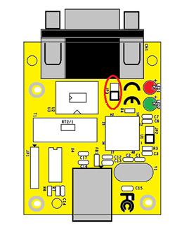
8 DIAGRAM OF USB-CAN-M/USB-CAN-SI-M PCB LAYOUT 6
9 BLOCK DIAGRAM USB-CAN-M Block Diagram USB-CAN-SI-M Block Diagram 7
10 SPECIFICATIONS The tables below show the specifications of USB to 1-port CAN bus adapter: General USB Bus Supports USB 1.1, USB 2.0, USB 3.0 CAN Bus Supports CAN 2.0A and CAN 2.0B Chipset ARM Cortex-M0 32-bit microcontroller Plug & Play Supported IRQ &IO Address Assigned by system Number of Ports Connector CAN Bus Speed Signals CAN Bus Controller LED CAN Bus Mode Protection One USB-CAN-M DB9 male connector 5kbits to 1Mbits for CAN data transmit & receive CAN_H, CAN_L, CAN_GND, CAN_V+ Bosch C_CAN module CAN bus data activity, CAN bus error Standard mode: normal operation on CAN bus Listen mode: passive receiving of CAN frames Echo mode: transmitter also receives sent frames (for testing purposes) +/-16 KV ESD protection for CAN signals 8
11 Number of Ports Connector CAN Bus Speed Signals CAN Bus Controller LED CAN Bus Mode Protection API Library Utility OS Driver Support Monitoring Tools Power Input Power Consumption One USB-CAN-SI-M DB9 male connector 20kbits to 1Mbits for CAN data transmit & receive CAN_H, CAN_L, CAN_GND, CAN_V+ Bosch C_CAN module CAN bus data activity, CAN bus error Standard mode: normal operation on CAN bus Listen mode: passive receiving of CAN frames Echo mode: transmitter also receives sent frames (for testing purposes) +/-16 KV ESD protection for CAN signals 2500V galvanic isolation on CAN bus Software Features Supports C/C++, C#, VB.NET and LabVIEW On-board firmware update utility Windows XP to Windows 10 OS Windows Server 2003 to 2012 R2 Supported by CANHacker, Titan CAN test program Power Requirement Power supplied via USB (5V) connector No external power needed Max. (USB-CAN-M) Max. (USB-CAN-SI-M) Mechanical Casing SECC sheet metal (1mm) Dimensions 61 mm x 50 mm x 23 mm (L x W x H) Weight 100g 9
12 Operating Temperature Storage Temperature Humidity Safety Approvals Environment 0 C to 60 C (32 F to 140 F) -20 C to 75 C (-4 F to 167 F) 5% to 95% RH CE, FCC 10
13 PIN-OUT INFORMATION Following are the pin-out of connector for USB to CAN bus adapter: CAN Bus Pin-out for DB9 connector Pin Number Signals Description 1 CAN_V+ Provides +DC 5V 100mA power (optional) 2 CAN_L CAN_L bus line (dominant level is low) 3 CAN_GND Signal ground 4 - Reserved 5 - Reserved 6 CAN_GND Signal ground 7 CAN_H CAN_H bus line (dominant level is high) 8 - Reserved 9 CAN_V+ Provides +DC 5V 100mA power (optional) Enabling the +5V 100mA power for external devices Inside the unit, there is a 2-pin header block (JP3) which are jumpers for enabling 5V 100mA power for external devices. JP3 Jumper ON OFF Function Enable DB9 pins 1 and 9 to provide a 5V 100mA power for external devices Disable the 5V 100mA power 11
14 Termination Resistors The USB CAN adapter does not provide CAN bus termination resistors. A CAN bus network requires 120Ω termination resistors at each end. Generally, this must be done in the cabling. Since this depends on the installation of connections, please check your CAN bus cable specification for proper impedance matching. 12
\" under Ports (COM & LPT) in device manager.")
15 HARDWARE INSTALLATION The USB CAN adapter is a plug and play device. In most cases, the USB CAN adapter s drivers will be installed automatically. Connect the USB CAN adapter to an unused USB port on your computer. After the software drivers are loaded, you will find a new "USB Serial Port (COMX)" under Ports (COM & LPT) in device manager. You will need to execute the command CAN_BAUDRATE_SET COMX to set the USB to CAN adapter to work in high speed (3Mbits). After executing the command, please disconnect the USB to CAN adapter from the system for about 5 seconds and connect it again (refer to page 27). Note: The set baud rate program (CAN_BAUDRATE_SET.exe) must be executed under command prompt with administrative privileges. 13

16 DRIVER AND SOFTWARE INSTALLATION Driver Installation In most cases, the driver of USB CAN adapter will be installed driver automatically. Windows 10, 8.1, 8, 7, Server 2012 R2, Server 2008 R2 Connect your computer to Internet and plug USB CAN adapter to the USB port. The driver will be installed automatically via Internet. Windows XP, Vista, Server 2003 and 2008 Connect your computer to Internet and plug USB CAN adapter to the USB port, when asked to install the drivers, allow your computer to search the Internet to load and install the drivers automatically. Verifying the Installation You can verify the installation by looking under device manager (Start Settings Control Panel System Properties Hardware Device Manager). The device should have installed as a "USB Serial Port (COMX)" under Ports (COM & LPT). 14
17 Changing COM Port Properties & COM Port Number This feature is particularly useful for programs such as HyperTerminal, which only work with COM1 through COM4. Please ensure that you do not change to a COM port number that is already in use. To change the virtual COM port properties: 1. Select the "USB Serial Port (COMX)". 2. Click Properties. 3. Select "Port Setting" and Advanced. 4. Click the drop down arrow on COM Port Number and scroll to the required COM port. 5. Select "OK". 6. Return to the Device Manager Screen. You will see that the USB Serial Port installation has been changed to the new COM Port Number. 15
18 FUNCTION DESCRIPTION LED Indicators The USB to CAN adapter has two LEDs (green LED & red LED) to indicate firmware initialization and CAN bus status for monitoring CAN bus channel status. The green LED indicates CAN bus data activity while the red LED indicates a CAN bus error. Following are the definition of different LED combinations: A: Power up (device initialized) After USB CAN powers up (device initialized), the USB to CAN adapter flashes the green and red LED four times to indicate that the USB CAN adapter has been initialized. B: CAN bus channel open/close When CAN bus channel opens, the green LED will turn on to indicate that the CAN bus channel is open; When CAN bus channel closes, the green LED will turn off to indicate that the CAN bus channel is closed. C: CAN Bus Data Activity When CAN data frame is sent or received, the green LED flashes continuously to indicate CAN bus data I/O activity. D: CAN Bus Error When an error occurs on the CAN bus, the red LED flashes continuously to indicated CAN bus error. 16
19 ASCII Command Set The USB CAN adapter can be registered as a virtual serial port on the host computer. With simple ASCII commands the USB CAN adapter can be controlled over this serial port. User can send/receive commands from any simple serial terminal program. Example: Set bitrate to 500Kbps, open CAN channel, send CAN frame (ID = 002h, DLC = 3, Data = ), close CAN: Command Response Function S6[CR] [CR] Set bitrate of USB CAN adapter to 500Kbps O[CR] [CR] Open CAN channel t [cr] z[cr] Send CAN message (ID = 002h, DLC = 3, Data = ) C[CR] [CR] Close CAN channel 17
20 Command list The commands are line based and terminated with newline character CR (0xD). On error the response will be 0x7 (BELL). The help command ( H, h or? ) will list supported commands. Command Response Function H[CR] h[cr]?[cr] [CR] [CR] [CR] List all supported commands Example: H[CR] Return Code List of Supported Commands: O Open the channel in Normal mode L Open the channel in Listen Only mode Y Open the channel in Loopback mode C Close CAN Channel S Set standard CAN bitrate s Set non-standard CAN bitrate t Transmit a standard frame T Transmit an extended frame r Transmit a standard remote request frame R Transmit an extended remote request frame Z Set timestamp on/off m Set acceptance mask M Set acceptance filter F Read status flag V Check software version N Check serial number m Set acceptance mask M Set acceptance filter RST Reset USB CAN Adapter H, h or? List supported commands 18
21 Opening the CAN Bus Channel The CAN bus channel will be opened with the command O[CR], L[CR] or Y[CR]. The command O[CR] will open the CAN bus channel in normal operation mode, the command L[CR] will open the CAN bus channel in listen only mode, in which no bus interaction will be done from the controller. the command Y[CR] will open the CAN bus channel in a loop-back mode, in which the USB to CAN adapter will also receive the frames that it sends. Before you use one of the commands, you should set a bitrate with the commands S or s. Command Response Function O[CR] [CR] Open the channel in Normal mode L[CR] [CR] Open the channel in Listen Only mode Y[CR] [CR] Open the channel in Loopback mode Closing the CAN Bus Channel The CAN bus channel will be closed with the command C[CR]. The command can only be used if the CAN bus channel is open. Command Response Function C[CR] [CR] Close the CAN channel if it is opened 19
22 Setting CAN Bitrate (Standard) The CAN bus bitrate can be set with the command SX[CR]. The command can only be used if the CAN bus channel is closed. Command Response Function S00[CR] [CR] Set the CAN bus bitrate to 5K S0[CR] [CR] Set the CAN bus bitrate to 10K S1[CR] [CR] Set the CAN bus bitrate to 20K S2[CR] [CR] Set the CAN bus bitrate to 50K S3[CR] [CR] Set the CAN bus bitrate to 100K S4[CR] [CR] Set the CAN bus bitrate to 125K S5[CR] [CR] Set the CAN bus bitrate to 250K S6[CR] [CR] Set the CAN bus bitrate to 500K S7[CR] [CR] Set the CAN bus bitrate to 800K S8[CR] [CR] Set the CAN bus bitrate to 1M Example: S6[CR] will be set USB CAN adapter to 500K bps CAN Bitrates. Note: The USB-CAN-SI-M only supports 20 K bits to 1 M bits. 20
![Setting CAN Bitrate (Advanced) A more user defined bus bitrate can be configured with the command sxxxxxxxxx[cr].](/docs-images/92/110472267/images/23-0.jpg "As with the standard bus timing command above, you can only use this command when the CAN bus channel is closed. sxxxxxxxxx [CR] sets the bitrate registers of the CAN controller.")
23 Setting CAN Bitrate (Advanced) A more user defined bus bitrate can be configured with the command sxxxxxxxxx[cr]. As with the standard bus timing command above, you can only use this command when the CAN bus channel is closed. sxxxxxxxxx [CR] sets the bitrate registers of the CAN controller. Users can set nonstandard bitrates which are not supported by the "SX" command. The USB to CAN adapter provides a CAN Bitrate Calculator program to calculate the value of CAN bitrate registers for setting non-standard bitrates. Follow these steps to calculate and set non-standard bitrates for the USB to CAN adapter: 1. Open the CAN Bitrate Calculator program. 2. Enter CAN Bitrate ( 150 for 150Kbps CAN Bitrate) in the field Desired bitrate:. 3. Click Calculate to calculate the value of CAN bitrate registers. 4. Remember the topmost value of CAN bitrate registers. 5. e.g. Command: s for 150 kbps CAN Bitrate. 6. Click Quit to exit the CAN Bitrate Calculator program. Example: s [cr] will be set the bitrate to 150Kbps. 21
24 Transmitting a Standard CAN Frame Transmitting a standard CAN frame (ID: 11 bit) over a CAN bus can be done with the command tiiildddd dd[cr]. The return value will be z[cr] or the normal error byte (BELL). The command is only available when the CAN bus channel is open. Command tiiildddd dd[cr] Response Function z[cr] Transmits a standard CAN message (11 bit) over the CAN bus iii: Standard CAN frame (11 bit) identifier in hexadecimal format (000-7FF). l: CAN data length (0-8) DLC, with the maximum value being 8 (8 bytes). dd: Data byte value in hexadecimal format (00-FF). The number of bytes must be equal to the data length field. Example: t ff[cr] will send a standard CAN frame with ID = 002h, DLC = 3, Data = FF. Transmitting a Standard Remote Request CAN Frame Transmitting a standard remote request CAN frame (ID: 11 bit) over a CAN bus can be done with the command riiil[cr]. The return value will be z[cr] or the normal error byte (BELL). The command is only available when the CAN bus channel is open. Command riiil[cr] Response Function z[cr] Transmits a standard remote request (11 bit) over the CAN bus iii: Standard remote request CAN frame (11 bit) identifier in hexadecimal format (000-7FF). l: CAN data length to request (0-8) DLC, with the maximum value being 8 (8 bytes). Example: r0023[cr] will send a standard remote request CAN frame with ID = 002h, DLC = 3 and request 3 data bytes. 22
25 Transmitting an Extended CAN Frame Transmitting an extended CAN frame (ID: 29 bit) over a CAN bus can be done with the command Tiiiiiiiildddd...dd[CR]. The return value will be Z[CR] or the normal error byte (BELL). The command is only available when the CAN bus channel is open. Command Tiiiiiiiildddd dd[cr] Response Function Z[CR] Transmits an extended CAN frame (11 bit) over the CAN bus iiiiiiii: Extended CAN frame (29 bit) identifier in hexadecimal format ( FFFFFFF). l: CAN data length (0-8) DLC, with the maximum value being 8 (8 bytes). dd: Data byte value in hexadecimal format (00-FF). The number of bytes must be equal to the data length field. Example: T1FFFFFFF [CR] will send an extended CAN frame with ID = 1FFFFFFFh, DLC = 3, data = Transmitting an Extended Remote Request CAN Frame Transmitting an extended remote request CAN frame (ID: 29 bit) over a CAN bus can be done with the command Riiiiiiiil[CR]. The return value will be Z[CR] or the normal error byte (BELL). The command is only available when the CAN bus channel is open. Command Riiiiiiiil[CR] Response Function Z[CR] Transmits an extended remote request (29 bit) over the CAN bus iiiiiiii: Extended remote request CAN frame (29 bit) identifier in hexadecimal format ( FFFFFFF). l: CAN data length to request (0-8) DLC, with the DLC maximum value being 8 (8 bytes). Example: R [CR] will send an extended remote request CAN frame with ID = h, DLC = 3 and request 3 data bytes. 23
26 Setting Timestamps ON/OFF The timestamp command will set the timestamp functionality of received frames ON or OFF. This command is only available when the CAN channel is closed. Command Z1[CR] Z0[CR] Response Function [CR] [CR] Set the timestamp functionality on received frames ON Set the timestamp functionality on received frames OFF 24
27 Setting Acceptance Mask The acceptance mask, in conjunction with the acceptance code (M), defines which CAN message frames (i.e. of a specific ID or range of CAN IDs) will be passed to the serial interface. The acceptance mask value corresponds to bits within a range of valid CAN IDs for either standard or extended CAN frames. This command is only active if the CAN channel is initiated and not opened. Set Acceptance Mask (m) command should be executed prior to Set Acceptance Code (M). Note: The CAN channel will revert to its prior state after execution. For example, if the channel is open when this command is executed, the channel will update the setting and return to the open state. Command Response Function miii[cr] miiiiiiii[cr] [CR] [CR] Set acceptance mask for standard CAN frame (11 bit) identifier Set acceptance mask for extended CAN frame (29 bit) identifier iii = standard 11-bit CAN mask (0x000 through 0x7FF) iiiiiiii = extended 29-bit CAN mask (0x through 0x1FFFFFFF) A value of 0 in a bit location indicates that the bit location ID value is to be ignored when filtering messages. Default is to pass all frames (acceptance mask = 0x000 for standard messages and 0x for extended messages) Example: m700[cr] set acceptance mask to check bits 10, 9 and 8 against the filter. Bits 7 through 0 are ignored as don t care. Use the acceptance mask in conjunction with the acceptance code, which is explained next. 25
28 Setting Acceptance Code The acceptance code/filter, in conjunction with the acceptance mask (m), defines which CAN message frames (i.e. of a specific ID or range of CAN IDs) will be passed to the serial interface. The acceptance code value corresponds to a valid CAN IDs for either standard or extended CAN frames. This command is only active if the CAN channel is initiated and not opened. The Set Acceptance Mask (m) command should be executed prior to the Set Acceptance Code (M) command. Note: The CAN channel will revert to its prior state after execution. For example, if the channel is open when this command is executed, the channel will update the setting and return to the open state. Command Response Function Miii[CR] Miiiiiiii[CR] [CR] [CR] Set acceptance code for standard CAN frame (11 bit) identifier Set acceptance code for extended CAN frame (29 bit) identifier iii = standard 11-bit CAN mask (0x000 through 0x7FF) iiiiiiii = extended 29-bit CAN mask (0x through 0x1FFFFFFF) Default is to pass all frames (acceptance code = 0x7FF for standard messages and 0x1FFFFFF for extended messages) Example: m1ff[cr] sets acceptance code to receive standard messages with the CAN ID of 0x1FF. If used in conjunction with the acceptance mask example above, frames of the range 0x100 through 0x1FF will be passed, and all other CAN IDs will be blocked. 26
29 Getting Status Flags User can use the command F[CR] to get the status bits when an error occurs. A twobyte BCD number is returned to correspond to the 8-bits of the internal register of the CAN controller. Command Response Function F[CR] XX[CR] Get CAN bus status Return Codes XX[CR] XX = CAN bus status (A bit set to 1 indicates a true condition): Bits 2, 1, 0: Last Error Code(LEC), The LEC field holds a code, which indicates the type of the last error to occur on the CAN bus. LEC Bits 2, 1, 0 Error Code 0 0, 0, 0 Error Code 1 0, 0, 1 Error Code 2 0, 1, 0 Error Code 3 0, 1, 1 Error Code 4 1, 0, 0 Error Code 5 1, 0, 1 Error Code 6 1, 1, 0 Error Code 7 1, 1, 1 Meaning No error. Stuff error: more than 5 equal bits in a sequence have occurred in a part of a received message where this is not allowed. Form error: a fixed format part of a received frame has the wrong format. ACK Error: the message this CAN core transmitted was not acknowledged by another node. Bit 1 error: during the transmission of a message (with the exception of the arbitration field), the device wanted to send a recessive level (bit of logical value 1 ), but the monitored bus value was dominant. Bit 0 error: Bit 1 error: during the transmission of a message (or acknowledged bit, or active error flag, or overload flag), the device wanted to send a dominant level (bit of logical value 0 ), but the monitored bus value was recessive. During the bus-off recovery, this status is set each time a sequence of 11 recessive bits have been monitored. This enables the CPU to monitor the proceedings of the bus-off recovery sequence (indicating the bus is not stuck at dominant or continuously disturbed). CRC error: the CRC checksum was incorrect in the message received, the CRC received for an incoming message does not match with the calculated CRC for the received data. Unused: no CAN bus event was detected since the CPU wrote this value to the LEC. 27
30 Bit 3: Transmitted a message successfully 1 = Since this bit was last reset by CPU, a message has been successfully (error-free and acknowledged by at least one other node) transmitted. 0 = Since this bit was last reset by CPU, no message has been transmitted. Bit 4: Received a message successfully 1 = A message has been successfully received since this bit was last reset by CPU (independent of the result of acceptance filtering). 0 = No message has been successfully received since this bit was last reset by CPU Bit 5: Error Passive (Read only) 1 = The CAN core is in the error passive state as defined in the CAN specification. 0 = The CAN core is in the error active. Bit 6: Error Warning Status (Read only) 1 = At least one of the error counters in the EML (Error Management Logic) has reached the error warning limit of 96. = Both error counters are below the error warning limit of 96. Bit 7: Bus-off Status (Read only) 1 = The CAN Module is in bus-off state. 0 = The CAN Module is not in bus-off state. <BELL> = ERROR Bit 0 ~ Bit 7 returned to correspond to the 8-bits of the internal register of the CAN controller. 28
31 Getting Version Information The command V[CR] to retrieve the current firmware version of the USB CAN adapter. Command Response Function V[CR] VXXXX[CR] Get the current firmware version of the USB CAN adapter This command is always available and will return the version information formatted like this: VXXXX[CR]. Getting Serial Number The command N[CR] will retrieve the serial number of the USB CAN adapter. Command Response Function N[CR] TXXXXXXXX[CR] Get the serial number of the USB CAN adapter This command is always available and will return the decimal serial number like this: TXXXXXXX[CR]. Resetting the USB CAN adapter The command RST[CR] will reset the USB CAN adapter. Command Response Function RST[CR] - Reset the USB CAN adapter This command is always available. 29
32 TOOLS Setting 3MBit Baud Rate for Better CAN Bus Performance To get a better performance, set the USB to CAN adapter to work in high speed (3Mbits). After executing the command, please disconnect the USB to CAN adapter from the system for about 5 seconds and connect it again. The set baud rate program (CAN_BAUDRATE_SET.exe) must be executed under command prompt with administrative privileges. Following is set baud rate program command: CAN_BAUDRATE_SET <COM-PORT> Example: CAN_BAUDRATE_SET COM7 COM7: the USB to CAN adapter installed as "USB Serial Port (COMX)". You can check the port number under Device Manager. After setting the baud rate successfully, you will find following message under Command Prompt : Searching Find COM PORT: COM7 Setting every baud rate to 3Mbit Set baud rate Success 30
 must be executed under Command Prompt with administrative privileges.")
33 Firmware Upgrade The USB to CAN adapter firmware can be updated for bug fixes and enhanced features. You can use our tool program to upgrade the firmware contents via serial port. The firmware upgrade program (can_fw_update.exe) must be executed under Command Prompt with administrative privileges. Following is the firmware upgrade command: can_fw_update <COM-PORT> <FIRMWARE FILE> Example: can_fw_update COM7 USBCAN_FW_V05.bin COM7: the USB to CAN adapter installed as "USB Serial Port (COMX)". You can check the port number under Device Manager. USBCAN_FW_V5.bin: new firmware file (binary file) of USB to CAN adapter. After executing the firmware upgrade successfully, you will find following message under Command Prompt : CONNECTING Serial Number: T Start: *************************************************************** **********************************************: END Update Success 31

34 CANHacker CANHacker is a Windows application software for analyzing and transmitting/receiving CAN frames. The CANHacker software has a friendly interface and is easy to use. Through the software user can easily test and analyze the CAN frames. Following shows its main panel: The following sections will briefly introduce the necessary steps on how to use the software. 32


35 Settings procedure for selecting and configuring the USB to CAN adapter 1. Open CANHacker and click Settings under the menu. 2. Select COM port of the USB to CAN adapter. 3. Check RTS HS to enable RTS handshake function. 4. Check Time Stamp to enable timestamp function. 5. Select CAN Baudrate for the CAN bus operating speed. 6. Finally, click OK to finish the settings and return to the main panel. You may connect the USB to CAN adapter after configuration. Click Connect, as shown in the figure, to start the CANHacker software operation. When USB to CAN adapter successfully connects, you will find the message Connected to XXX kbits/s, firmware version VXXXX and operation mode at the 33

36 bottom of the main panel. 34

 or a standard CAN frame (11 bits ID).")
37 Receiving CAN frames When CANHacker receives CAN frames from another CAN node, it will show all CAN frame messages in the middle of main panel. The CAN frame messages includes ID, DLC, Data, Period, Count. Sending CAN frames CANHacker provides many parameters for sending CAN frames to another CAN node, you can set the following parameters on the bottom of the main panel for CAN data transmission: Select transmit an extended CAN Frame (29 bits ID) or a standard CAN frame (11 bits ID). Check 29 Bit Id uncheck 29 Bit Id to transmit an extended CAN Frame (29 bits ID) and to transmit a standard CAN frame (11 bits ID). Select remote request frame mode or transmit CAN frame mode. Check RTR for a remote request frame mode or uncheck RTR for transmit CAN frame mode. Enter CAN frame messages in the respective fields, including ID, DLC, Data. 35
38 In TX Mode dialog box, you can select off, Periodic, RTR, Trigger modes. When Periodic mode is selected, you can enter Period(ms) to send CAN frames message repeatedly (enter 500 to send CAN messages every 500ms). To send a single CAN frame message, click Single Shot. Click Send All to send CAN frames message repeatedly. To stop sending CAN frame messages, click Stop All. 36

 count.")
39 Assistant features There are many assistant features included in CANHacker, as shown in the figure below: Saving data to file or loading data from file: Select File option to save Rx List, Trace, Tx List, Command List and Load Trace, Tx List, Command List. Click Disconnect to stop CANHacker. Click Reset to renew the received CAN frame messages and reset the transmission (received) count. 37


40 Select Filter to set mask filter and range filter. Select Tracer or Monitor to trace or monitor the CAN frame messages. 38

41 Titan CAN Test Program Titan CAN test program is a Windows application software for testing and transmitting/receiving CAN frames. The Titan CAN test program is an easy to use software. Through the software users can easily test and analyze the CAN frames. Following shows its main panel: The following section will briefly introduce the necessary steps on how to use the Titan CAN test program. 39


42 Settings procedure for selecting and configuring the USB to CAN adapter 1. Open Titan CAN test program and click Settings under the menu. 2. Select COM port of the USB to CAN adapter. 3. Select CAN Baudrate for the CAN bus operating speed. 4. Check Time Stamp to enable timestamp function. 5. Check LoopBack or ListenOnly to open the CAN bus adapter in loopback or listen only operation mode, otherwise the CAN bus adapter will open in normal operation mode. 6. Finally, click OK to finish the settings and return to the main panel. You may connect the USB to CAN adapter after configuration. Click Connect, as shown in the figure, to start the Titan CAN test program operation. When USB to CAN adapter successfully connects, you will find the message Connected to XXX kbits/s, firmware version VXXXX and operation mode at the bottom of the main panel. 40

43 41

44 Receiving CAN frames When Titan CAN test program receives CAN frames from another CAN node, it will show all CAN frame messages in middle of main panel. The CAN frame messages includes ID, DLC, Data, Period, Count. Sending CAN frames Titan CAN test program provides many parameters for sending CAN frames to another CAN node, you can set the following parameters on the bottom of the main panel for CAN data transmission: Select transmit an extended CAN frame (29 bits ID) or a standard CAN frame (11 bits ID). Check Extend Extend to transmit an extended CAN Frame (29 bits ID) and uncheck to transmit a standard CAN frame (11 bits ID). Select remote request frame mode or transmit CAN frame mode. Check RTR for a remote request frame mode or uncheck RTR for transmit CAN frame mode. Enter CAN frame messages in the respective fields, including ID, DLC, Data. 42
45 When Periodic mode is selected, you can enter Period(ms) to send CAN frames message repeatedly (enter 100 to send CAN messages every 100ms). To send a single CAN frame message, click Single Shot. Click Send All to send CAN frames message repeatedly. To stop sending CAN frame messages, click Stop All. To add a new send CAN frame message, click Add to add new send CAN frame message and click Copy to copy a send CAN frame message repeatedly. To delete a send CAN frame message, click Delete to delete send CAN frame message. 43


46 Assistant features There are many assistant features included in Titan CAN test program, as shown in the figure below: Select File option to save Rx List, Tx List and Load Tx List. Click Disconnect to stop Titan CAN test program. Select Filter to set mask filter and range filter. 44


47 Mask Filter: Set Acceptance Code Register and Acceptance Mask Register for CAN bus controller to specify the CAN IDs that are passed or blocked; after setting Mask and Code, check Enable Mask Filter then click OK to finish the Mask Filter settings and return to the main panel. Note: Before you set the Mask Filter function, you need to disconnect the USB adapter. After setting the value of Mask + Code, connect the USB adapter again to enable the Mask Filter function, because the Mask Filter function is only available if the CAN adapter is initiated and not opened. Mask Filter example: After setting Mask to 1FFFFFF0 and Code to , CAN message frames of the range 0x through 0x F will be passed and all other CAN IDs will be blocked. 45


48 Range Filter: Set Start ID and Stop ID for USB CAN adapter to specify a range of CAN IDs that are to be passed; after setting Start ID and Stop ID, check Enable Range Filter then click OK to finish the Ranger Filter settings and return to the main panel. Range Filter example: After setting Start ID to and End ID to 01FFFFFF, The CAN message frames of the range 0x through 0x01FFFFFF will be passed and all other CAN IDs will be blocked. The Range Filter can also set Discrete IDs to block a unique CAN ID. Discrete IDs Filter example: After setting Start ID to , End ID to 01FFFFFF and setting Discrete IDs to ; The CAN ID range 0x through 0x01FFFFFF will be passed but only CAN ID 0x will be blocked. 46


49 Click Reset option to renew the received CAN frame message and reset the transmitted (received) count. Click About option to show the version information of Titan CAN test program. 47
50 APPLICATION PROGRAMMING INTERFACE The Application Programming Interface (API) gives the user tools to use all of the functions that the CAN adapter provides. It will make it much easier for users to build their own CAN controlling software with these functions, than to implement their application command by command on the ASCII protocol. Users can use Windows-based API for use with high-level languages. Please refer to the following website for our GUI, sample codes and updates: 48
51 CAN_Open CAN_Open(ComPort, szbitrate, acceptance_code, acceptance_mask, flags, Mode) Function: Opens a channel to the device. Parameters: ComPort o Type: String o The COM port to be opened. o Format: COMXXX o Example: COM1, COM57, COM118 szbitrate o Type: String o The bitrate to operate at. Can be one of the standard bitrates or a userdefined non-standard bitrate. o Format: 10 = 10Kbps 20 = 20Kbps 50 = 50Kbps 100 = 100Kbps 125 = 125Kbps 250 = 250Kbps 500 = 500Kbps 800 = 800Kbps 1000 = 1000Kbps XXXXXXXXX, non-standard bitrate o Example: 50, 1000, acceptance_code o Type: String o Used in conjunction with the acceptance mask to filter CAN messages. Set to for NULL to allow all messages. Also referred to as acceptance filter in other parts of the manual. o Format: XXXXXXXX o Example: acceptance_mask o Type: String o Used in conjunction with the acceptance code to filter CAN messages. Set to for NULL to allow all messages. o Format: XXXXXXXX o Example: FF 49
52 flags o Type: IntPtr o Determines whether or not the timestamp function should be enabled. o Format: 1 = Timestamp will be enabled 0 = Timestamp will be disabled o Example: 1 Mode o Type: Integer o Determines the mode the USB CAN should operate at. o Format: 0 = Normal, the device will operate under normal circumstances 1 = Listen only, the device will passively receive CAN messages 2 = Loopback, the device will also receive messages it transmits o Example: 2 Return value: o Type: Integer o Handle to the device. o Result: > 0, CAN_Open is successful -1, error communicating with COM port -2, error in opening channel, COM port may be already in use -3, error in parameter settings o Example: 2508 Sample Command: CAN_Open( COM3, 50, , , 1, 2) Opens a channel to COM3 at 50kbps, with all messages allowed, timestamp enabled and operating in loopback mode. 50
53 CAN_Close CAN_Close(Handle) Function: Closes the channel with the specified handle. Parameters: Handle o Type: Integer o The handle of the CAN channel to be closed. o Format: A numeric value provided by the return value of CAN_Open o Example: 2508 Return value: o Type: Integer o Code indicating result of CAN_Close. o Result: 1, CAN_Close is successful -1, error communicating with COM port -4, error: CAN channel is not open Sample Command: CAN_Close(2508) Closes device connected to channel with the handle
54 CAN_Write CAN_Write(Handle, Buf) Function: Writes a message to the channel with the specified handle. Parameters: Handle o Type: Integer o The handle of the CAN channel to write to. o Format: A numeric value provided by the return value of CAN_Open o Example: 2508 Buf 1 o Type: CAN_MSG structure o The standard structure of CAN frame messages. o Format: Name of an instance of the CAN_MSG structure o Example: mycanmsg Return value: o Type: Integer o Code indicating result of CAN_Write. o Result: 1, CAN_Write is successful -1, error communicating with COM port -4, error: CAN channel is not open Sample Command: CAN_Write(2508, mycanmsg) Writes the message contained in mycanmsg to device connected to channel with the handle Refer to the CAN_MSG Structure section for more information 52
55 CAN_Read CAN_Read(Handle, Buf) Function: Reads a message from the channel with the specified handle. Parameters: Handle o Type: Integer o The handle of the CAN channel to read from. o Format: A numeric value provided by the return value of CAN_Open o Example: 2508 Buf 2 o Type: CAN_MSG structure o The standard structure of CAN frame messages. o Format: Name of an instance of the CAN_MSG structure o Example: mycanmsg Return value: o Type: Integer o Code indicating result of CAN_Read. o Result: 1, CAN_Read is successful -1, error communicating with COM port -4, error: CAN channel is not open -5, error: there are no messages Sample Command: CAN_Read(2508, mycanmsg) Reads the message from device connected to channel with the handle 2508 and stores it into mycanmsg. 2 Refer to the CAN_MSG Structure section for more information 53
56 CAN_Flush CAN_Flush(Handle) Function: Clears the buffers of the channel with the specified handle. Parameters: Handle o Type: Integer o The handle of the CAN channel whose buffers are to be cleared. o Format: A numeric value provided by the return value of CAN_Open o Example: 2508 Return value: o Type: Integer o Code indicating result of CAN_Flush. o Result: 1, CAN_Flush is successful -1, error communicating with COM port -4, error: CAN channel is not open Sample Command: CAN_Flush(2508) Clears the buffers of device connected to channel with the handle
57 CAN_Status CAN_Status(Handle) Function: Checks the status bits for more specific details when an error occurs. Parameters: Handle o Type: Integer o The handle of the CAN channel whose status bits are to be inquired. o Format: A numeric value provided by the return value of CAN_Open o Example: 2508 Return value: o Type: Integer o Code indicating result of CAN_Status. o Result: Bit [2, 1, 0] 0, 0, 0: no error 0, 0, 1: stuff error 0, 1, 0: form error 0, 1, 1: ACK error 1, 0, 0: Bit1Error 1, 0, 1: Bit0Error 1, 1, 0: CRCError 1, 1, 1: unused Bit [3] 1: message successfully transmitted 0: no message has been transmitted Bit [4] 1: message successfully received 0: no message has been received Bit [5] 1: CAN core is in error passive state 0: CAN core is in error active state Bit [6] 1: at least one error counter in EML has reached the warning limit of 96 0: both error counters are below the warning limit of 96 Bit [7] 1: CAN module is in bus-off state 0: CAN module is not in bus-off state <BELL> = ERROR 55
58 Sample Command: CAN_Status(2508) Checks the status bits of device connected to channel with the handle
59 CAN_Version CAN_Version(Handle, buf) Function: Retrieves the firmware version of the device connected to channel with the specified handle. Parameters: Handle o Type: Integer o The handle of the CAN channel whose version information is to be inquired. o Format: A numeric value provided by the return value of CAN_Open o Example: 2508 buf o Type: Character array/string o Information about the firmware version will be stored into this array. o Format: Name of a character array o Example: myversion Return value: o Type: Integer o Code indicating result of CAN_Version. o Result: 1, CAN_Version is successful -1, error communicating with COM port -4, error: CAN channel is not open Sample Command: CAN_Version(2508) Retrieves the firmware version of device connected to channel with the handle
60 CAN_MSG Structure Members: o Id Type: Unsigned Integer Message ID. Format: XXX (standard), XXXXXXXX (extended) Example: 1FF o Size Type: Byte Message size. Format: A numeric value from 0~8 Example: 8 o Data Type: Byte array with 8 elements Content of the data to be sent/received. Format: XX Example: 11 o Flags Type: Byte Determines the message ID type and timestamp settings. Format: 1, timestamp off, standard 2, timestamp off, extended 9, timestamp on, standard 10, timestamp on, extended Example: 9 o Timestamp Type: Unsigned Short Value of the timestamp. Format: No input from the user is required Example: 0 Sample Message: o With a CAN_MSG structure instance declared as mycanmsg: mycanmsg.id = 1FF mycanmsg.size = 3 mycanmsg.data(0) = 11 mycanmsg.data(1) = 22 mycanmsg.data(2) = 33 mycanmsg.flags = 10 58
61 Using the API in Visual Basic.NET 1. Ensure that the DLL file is placed in the same folder as your application executable. 2. Import the functions you need from the DLL into your source code with the Declare statement: Private Declare Function CAN_Open Lib "CANDLL_STDCALL.dll" (ByVal ComPort As String, ByVal szbitrate As String, ByVal acceptance_code As String, ByVal acceptance_mask As String, ByRef Flags As IntPtr, ByVal Mode As Integer) As Integer 3. Create a definition of the CAN_MSG structure for the CAN_Write and CAN_Read functions, if needed. Imports System.Runtime.InteropServices Public Structure CAN_MSG <MarshalAs(UnmanagedType.U4)> Public Id As UInteger <MarshalAs(UnmanagedType.U1)> Public Size As Byte <MarshalAs(UnmanagedType.ByValArray, SizeConst:=8, ArraySubType:=UnmanagedType.U1)> Public Data As Byte() <MarshalAs(UnmanagedType.U1)> Public Flags As Byte <MarshalAs(UnmanagedType.U2)> Public Timestamp As UShort End Structure The keyword MarshalAs is used for all structure members to ensure that the structure size corresponds to what the DLL expects. To use the CAN_MSG structure, you will need to create an instance of the structure you just defined. Private mycanmsg As CAN_MSG Before accessing this instance you just created for the first time, set the size for the Data member to avoid array out of bounds error. This can be done in your program s constructor. ReDim mycanmsg(7) 59
62 4. In order to communicate with the channel with other functions after opening it with CAN_Open, you need to create a variable to store the handle value. Private myhandle As Integer myhandle = CAN_Open(("COM3", "50", " ", " ", 1, 2) 5. This concludes the basic setup process of using the DLL in Visual Basic.NET. Imported functions can then be easily called from the DLL with the parameters created above. 60
63 Using the API in Visual Basic Ensure that the DLL file is placed in the same folder as your application executable. 2. Import the functions you need from the DLL into your source code with the Declare statement: Private Declare Function CAN_Open Lib "CANDLL_STDCALL.dll" (ByVal ComPort As String, ByVal szbitrate As String, ByVal acceptance_code As String, ByVal acceptance_mask As String, ByRef Flags As Long, ByVal Mode As Long) As Long 3. Create a definition of the CAN_MSG structure for the CAN_Write and CAN_Read functions, if needed. Private Type CAN_MSG Id As Long Size As Byte Data(0 To 7) As Byte Flags As Byte Timestamp As Integer End Type To use the CAN_MSG structure, you will need to create an instance of the structure you just defined. Private mycanmsg As CAN_MSG 4. In order to communicate with the channel with other functions after opening it with CAN_Open, you need to create a variable to store the handle value. Private myhandle As Long myhandle = CAN_Open(("COM3", "50", " ", " ", 1, 2) 5. This concludes the basic setup process of using the DLL in Visual Basic 6.0. Imported functions can then be easily called form the DLL with the parameters created above. 61
64 Using the API in Python 6. Ensure that the DLL file is placed in the same folder as your application executable. 7. Import the DLL using the ctypes library function LoadLibrary. from ctypes import windll DLL = windll.loadlibrary("candll_stdcall.dll") 8. Create a definition of the CAN_MSG structure for the CAN_Write and CAN_Read functions, if needed. from ctypes import Structure, c_uint, c_ubyte, c_ushort class CAN_MSG(Structure): _fields_ = [("Id", c_uint), ("Size", c_ubyte), ("Data", c_ubyte * 8 ), ("Flags", c_ubyte), ("Timestamp", c_ushort)] To use the CAN_MSG structure, you will need to create an instance of the structure you just defined. mycanmsg = CAN_MSG() 9. In order to communicate with the channel with other functions after opening it with CAN_Open, you need to create a variable to store the handle value. myhandle = DLL.CAN_Open(b"COM3", b"50", b" ", b" ", 1, 2) 10. This concludes the basic setup process of using the DLL in Python. Imported functions can then be easily called form the DLL with the parameters created above. 62


65 Using the API in LabVIEW CAN_Main.vi The main panel is a simple, easy-to-use example program which contains most of the important functions available for use in the CAN API. Different functions can be tested by changing the settings on the leftmost side, which are restricted to legal parameters to prevent an error in operation. For example, the user can choose from Normal, Listen Only, or Loopback mode to suit their purposes. Once the channel is opened, the user can use either Write Once or the Write Repeatedly button to send messages as configured in the fields. Messages received will appear on the fields on the rightmost side, if they are available. All subvi icons have been customized, with the terminals wired to be user-friendly, increase readability and allow for cleanliness in larger projects, as seen in the block diagram for the main panel. 63

66 CAN_Open.vi Description Opens a channel to the device. Input o ComPort: The COM port to establish a connection with. o szbitrate: The speed at which the connection is to be made, with preset values of 10, 20, 50, 100, 125, 250, 500, 800, 100 o acceptance_code: Used for filtering CAN messages. To be used with the acceptance mask. o acceptance_mask: Used for filtering CAN messages. To be used with the acceptance code. o Flags: Whether or not the timestamp function should be enabled. o Mode: The mode at which the device should operate at, with choices being Normal, Listen Only and Loopback Output o Return: Handle to the device. A positive value indicates success in opening the channel, while -2 represents error when opening channel and -3 represents error in input parameters 64

67 CAN_Close.vi Description Closes the CAN channel with the specified handle. Input Handle: The handle of the CAN channel which is to be closed Output Return: A positive value indicates success in closing the channel, whereas a negative value indicates an error in closing the channel. 65
USB-CAN USER S MANUAL
 USB-CAN USER S MANUAL 2017-07-06 Edition Titan Electronics Inc. Web: www.titan.tw The computer programs provided with the hardware are supplied under a license. The software provided should be used only
Produkt-Datenblatt. Technische Daten, Spezifikationen. MEsstechnik fängt mit ME an. Kontakt
 Produkt-Datenblatt Technische Daten, Spezifikationen Kontakt Technischer und kaufmännischer Vertrieb, Preisauskünfte, Angebote, Test-Geräte, Beratung vor Ort: Tel: (0 81 41) 52 71-0 FAX: (0 81 41) 52 71-129
Produkt-Datenblatt. Technische Daten, Spezifikationen. MEsstechnik fängt mit ME an. Kontakt
 Produkt-Datenblatt Technische Daten, Spezifikationen Kontakt Technischer und kaufmännischer Vertrieb, Preisauskünfte, Angebote, Test-Geräte, Beratung vor Ort: Tel: (0 81 41) 52 71-0 FAX: (0 81 41) 52 71-129
Produkt-Datenblatt. Technische Daten, Spezifikationen. MEsstechnik fängt mit ME an. Kontakt
 Produkt-Datenblatt Technische Daten, Spezifikationen Kontakt Technischer und kaufmännischer Vertrieb, Preisauskünfte, Angebote, Test-Geräte, Beratung vor Ort: Tel: (0 81 41) 52 71-0 FAX: (0 81 41) 52 71-129
Produkt-Datenblatt. Technische Daten, Spezifikationen. MEsstechnik fängt mit ME an. Kontakt
 Produkt-Datenblatt Technische Daten, Spezifikationen Kontakt Technischer und kaufmännischer Vertrieb, Preisauskünfte, Angebote, Test-Geräte, Beratung vor Ort: Tel: (0 81 41) 52 71-0 FAX: (0 81 41) 52 71-129
Produkt-Datenblatt. Technische Daten, Spezifikationen. MEsstechnik fängt mit ME an. Kontakt
 Produkt-Datenblatt Technische Daten, Spezifikationen Kontakt Technischer und kaufmännischer Vertrieb, Preisauskünfte, Angebote, Test-Geräte, Beratung vor Ort: Tel: (0 81 41) 52 71-0 FAX: (0 81 41) 52 71-129
Produkt-Datenblatt. Technische Daten, Spezifikationen. MEsstechnik fängt mit ME an. Kontakt
 Produkt-Datenblatt Technische Daten, Spezifikationen Kontakt Technischer und kaufmännischer Vertrieb, Preisauskünfte, Angebote, Test-Geräte, Beratung vor Ort: Tel: (0 81 41) 52 71-0 FA: (0 81 41) 52 71-129
Produkt-Datenblatt. Technische Daten, Spezifikationen. MEsstechnik fängt mit ME an. Kontakt
 Produkt-Datenblatt Technische Daten, Spezifikationen Kontakt Technischer und kaufmännischer Vertrieb, Preisauskünfte, Angebote, Test-Geräte, Beratung vor Ort: Tel: (0 81 41) 52 71-0 FAX: (0 81 41) 52 71-129
Produkt-Datenblatt. Technische Daten, Spezifikationen. MEsstechnik fängt mit ME an. Kontakt
 Produkt-Datenblatt Technische Daten, Spezifikationen Kontakt Technischer und kaufmännischer Vertrieb, Preisauskünfte, Angebote, Test-Geräte, Beratung vor Ort: Tel: (0 81 41) 52 71-0 FAX: (0 81 41) 52 71-129
Produkt-Datenblatt. Technische Daten, Spezifikationen. MEsstechnik fängt mit ME an. Kontakt
 Produkt-Datenblatt Technische Daten, Spezifikationen Kontakt Technischer und kaufmännischer Vertrieb, Preisauskünfte, Angebote, Test-Geräte, Beratung vor Ort: Tel: (0 81 41) 52 71-0 FAX: (0 81 41) 52 71-129
Produkt-Datenblatt. Technische Daten, Spezifikationen. MEsstechnik fängt mit ME an. Kontakt
 Produkt-Datenblatt Technische Daten, Spezifikationen Kontakt Technischer und kaufmännischer Vertrieb, Preisauskünfte, Angebote, Test-Geräte, Beratung vor Ort: Tel: (0 81 41) 52 71-0 FAX: (0 81 41) 52 71-129
Produkt-Datenblatt. Technische Daten, Spezifikationen. MEsstechnik fängt mit ME an. Kontakt
 Produkt-Datenblatt Technische Daten, Spezifikationen Kontakt Technischer und kaufmännischer Vertrieb, Preisauskünfte, Angebote, Test-Geräte, Beratung vor Ort: Tel: (0 81 41) 52 71-0 FAX: (0 81 41) 52 71-129
Produkt-Datenblatt. Technische Daten, Spezifikationen. MEsstechnik fängt mit ME an. Kontakt
 Produkt-Datenblatt Technische Daten, Spezifikationen Kontakt Technischer und kaufmännischer Vertrieb, Preisauskünfte, Angebote, Test-Geräte, Beratung vor Ort: Tel: (0 81 41) 52 71-0 FAX: (0 81 41) 52 71-129
Produkt-Datenblatt. Technische Daten, Spezifikationen. MEsstechnik fängt mit ME an. Kontakt
 Produkt-Datenblatt Technische Daten, Spezifikationen Kontakt Technischer und kaufmännischer Vertrieb, Preisauskünfte, Angebote, Test-Geräte, Beratung vor Ort: Tel: (0 81 41) 52 71-0 FAX: (0 81 41) 52 71-129
Produkt-Datenblatt. Technische Daten, Spezifikationen. MEsstechnik fängt mit ME an. Kontakt
 Produkt-Datenblatt Technische Daten, Spezifikationen Kontakt Technischer und kaufmännischer Vertrieb, Preisauskünfte, Angebote, Test-Geräte, Beratung vor Ort: Tel: (0 81 41) 52 71-0 FAX: (0 81 41) 52 71-129
Produkt-Datenblatt. Technische Daten, Spezifikationen. MEsstechnik fängt mit ME an. Kontakt
 Produkt-Datenblatt Technische Daten, Spezifikationen Kontakt Technischer und kaufmännischer Vertrieb, Preisauskünfte, Angebote, Test-Geräte, Beratung vor Ort: Tel: (0 81 41) 52 71-0 FAX: (0 81 41) 52 71-129
Kontakt. Internet: Web Kontakt-Formular:
 Application Notes, Whitepapers Acromag Industrial I/O Produkte Kontakt Technischer und kaufmännischer Vertrieb, Preisauskünfte, Angebote, Test-Geräte, Beratung vor Ort: Tel: (0 89) 89 01 66-0 FAX: (0 89)
Produkt-Datenblatt. Technische Daten, Spezifikationen. MEsstechnik fängt mit ME an. Kontakt
 Produkt-Datenblatt Technische Daten, Spezifikationen Kontakt Technischer und kaufmännischer Vertrieb, Preisauskünfte, Angebote, Test-Geräte, Beratung vor Ort: Tel: (0 81 41) 52 71-0 FAX: (0 81 41) 52 71-129
Produkt-Datenblatt. Technische Daten, Spezifikationen. MEsstechnik fängt mit ME an. Kontakt
 Produkt-Datenblatt Technische Daten, Spezifikationen Kontakt Technischer und kaufmännischer Vertrieb, Preisauskünfte, Angebote, Test-Geräte, Beratung vor Ort: Tel: (0 81 41) 52 71-0 FAX: (0 81 41) 52 71-129
Produkt-Datenblatt. Technische Daten, Spezifikationen. MEsstechnik fängt mit ME an. Kontakt
 Produkt-Datenblatt Technische Daten, Spezifikationen Kontakt Technischer und kaufmännischer Vertrieb, Preisauskünfte, Angebote, Test-Geräte, Beratung vor Ort: Tel: (0 81 41) 52 71-0 FAX: (0 81 41) 52 71-129
Produkt-Datenblatt. Technische Daten, Spezifikationen. MEsstechnik fängt mit ME an. Kontakt
 Produkt-Datenblatt Technische Daten, Spezifikationen Kontakt Technischer und kaufmännischer Vertrieb, Preisauskünfte, Angebote, Test-Geräte, Beratung vor Ort: Tel: (0 81 41) 52 71-0 FAX: (0 81 41) 52 71-129
PCIe-400 USER S MANUAL
 PCIe-400 USER S MANUAL 2017 May Edition Titan Electronics Inc. Web: www.titan.tw The computer programs provided with the hardware are supplied under a license. The software provided should be used only
Produkt-Datenblatt. Technische Daten, Spezifikationen. MEsstechnik fängt mit ME an. Kontakt
 Produkt-Datenblatt Technische Daten, Spezifikationen Kontakt Technischer und kaufmännischer Vertrieb, Preisauskünfte, Angebote, Test-Geräte, Beratung vor Ort: Tel: (0 81 41) 52 71-0 FAX: (0 81 41) 52 71-129
Produkt-Datenblatt. Technische Daten, Spezifikationen. MEsstechnik fängt mit ME an. Kontakt
 Produkt-Datenblatt Technische Daten, Spezifikationen Kontakt Technischer und kaufmännischer Vertrieb, Preisauskünfte, Angebote, Test-Geräte, Beratung vor Ort: Tel: (0 81 41) 52 71-0 FAX: (0 81 41) 52 71-129
Produkt-Datenblatt. Technische Daten, Spezifikationen. MEsstechnik fängt mit ME an. Kontakt
 Produkt-Datenblatt Technische Daten, Spezifikationen Kontakt Technischer und kaufmännischer Vertrieb, Preisauskünfte, Angebote, Test-Geräte, Beratung vor Ort: Tel: (0 81 41) 52 71-0 FAX: (0 81 41) 52 71-129
NCOM SERIAL DEVICE SERVER 4XX SERIES USER S MANUAL
 NCOM SERIAL DEVICE SERVER 4XX SERIES USER S MANUAL 2017-07-07 Edition Titan Electronics Inc. Web: www.titan.tw Contents 1. INTRODUCTION... 4 1.1 Key Features... 5 1.2 Specifications... 6 2. PANEL LAYOUT
NCOM SERIAL DEVICE SERVER 1XX SERIES USER S MANUAL
 NCOM SERIAL DEVICE SERVER 1XX SERIES USER S MANUAL 2017-07-07 Edition Titan Electronics Inc. Web: www.titan.tw Contents 1. INTRODUCTION... 4 1.1 Key Features... 5 1.2 Specifications... 6 2. PANEL LAYOUT
PCI Express 4-Port Industrial Serial I/O Cards
 PCI Express 4-Port Industrial Serial I/O Cards The PCIe-400i and PCIe-400i-SI PCI Express 4-port industrial serial I/O cards are plug & play high-speed serial I/O expansion cards for the PCI Express bus.
Introduction & Specifications of Hi-Speed USB to Industrial Dual Ports RS-422/485 Adapter
 Introduction & Specifications of Hi-Speed USB to Industrial Dual Ports RS-422/485 Adapter USB to Dual RS-422/485 Adapter (USB-2COMi-M) USB to Dual Opto-isolated RS-422/485 Adapter (USB-2COMi-SI-M) - with
Installation Guide of Hi-Speed USB to Industrial Single RS-422/485 Adapter
 Installation Guide of Hi-Speed USB to Industrial Single RS-422/485 Adapter Introduction of USB-COMi and USB-COMi-SI The USB-COMi and USB-COMi-SI Industrial Single RS-422/485 Adapters are designed to make
Produkt-Datenblatt. Technische Daten, Spezifikationen. MEsstechnik fängt mit ME an. Kontakt
 Produkt-Datenblatt Technische Daten, Spezifikationen Kontakt Technischer und kaufmännischer Vertrieb, Preisauskünfte, Angebote, Test-Geräte, Beratung vor Ort: Tel: (0 81 41) 52 71-0 FAX: (0 81 41) 52 71-129
Installation Guide of Hi-Speed USB to Industrial I/O Adapter
 Installation Guide of Hi-Speed USB to Industrial I/O Adapter Introduction of USB-COMi-SI-M The USB Industrial I/O Adapter is designed to make industrial communication port expansion quick and simple. Connecting
SER-4485-SI-M USER S MANUAL
 SER-4485-SI-M USER S MANUAL 2017 May Edition Titan Electronics Inc. Web: www.titan.tw The computer programs provided with the hardware are supplied under a license. The software provided should be used
Introduction & Specifications of Hi-Speed USB to Serial Adapters
 Introduction & Specifications of Hi-Speed USB to Serial Adapters The USB Serial Adapters consist of the following models: USB Single Serial Adapter (ES-U-1001, ES-U-1001-A) USB Single Serial Adapter (ES-U-1001-M,
Installation Guide of Hi-Speed USB-to-Optically Isolated RS-422/485 Adapter
 Installation Guide of Hi-Speed USB-to-Optically Isolated RS-422/485 Adapter Introduction of ES-U-2101-M The USB-to-Optically Isolated RS-422/485 Adapter is designed to make industrial communication port
USB-COMi-TB USB to Industrial Single RS-422 / 485 Adapter Manual. Specifications and Features
 USB-COMi-TB USB to Industrial Single RS-422 / 485 Adapter Manual The USB-COMi-TB USB-to-Industrial Single RS-422/485 Adapter is designed to make industrial communication port expansion quick and simple.
USB-16COMi-M 16-Port RS-422/485 USB Serial Adapter User Manual. Features and Specifications. Power Supply
 USB-16COMi-M 16-Port RS-422/485 USB Serial Adapter User Manual The USB to industrial 16-Port RS-422/485 Adapter is designed to make serial port expansion quick and simple. Connecting to a USB port on your
Produkt-Datenblatt. Technische Daten, Spezifikationen. MEsstechnik fängt mit ME an. Kontakt
 Produkt-Datenblatt Technische Daten, Spezifikationen Kontakt Technischer und kaufmännischer Vertrieb, Preisauskünfte, Angebote, Test-Geräte, Beratung vor Ort: Tel: (0 81 41) 52 71-0 FAX: (0 81 41) 52 71-129
This 4-port RS-422/485 Adapter is provided with an external switching power adapter in the package.
 USB-4COMi-M USB to Quad RS-422/485 to Serial Adapter Manual The USB to Industrial Quad RS-422/485 Adapter is designed to make industrial communication port expansion quick and simple. Connecting to a USB
Installation Guide of Hi-Speed USB to Octal RS-232/422/485 Adapter
 Installation Guide of Hi-Speed USB to Octal RS-232/422/485 Adapter Introduction The USB to Octal Serial Adapter is designed to make serial port expansion quick and simple. Connecting to a USB port on your
USB SERIAL OVER IP ADAPTER AnyplaceUSB-xCOM USER S MANUAL
 USB SERIAL OVER IP ADAPTER AnyplaceUSB-xCOM USER S MANUAL 2018 August Edition Titan Electronics Inc. Sharing Serial Ports over Ethernet and the Internet www.titan.tw The computer programs provided with
PCI Express 16-Port Serial I/O Cards
 PCI Express 16-Port Serial I/O Cards The PCIe-1600 PCI Express 16-port serial I/O card is a plug & play high-speed serial I/O expansion card for PCI Express bus. Connecting to a PCI Express bus on your
CAN232 Version 3 Manual
 Version 3 Manual February 2010 Manual Version 3.0 In this manual are descriptions for copyrighted products that are not explicity indicated as such. The absence of the copyright symbol does not infer that
Product Manual. 2 Port USB to RS-422 /485 Optical Isolated Adapter. Coolgear, Inc. Version 1.1 March 2018 Model Number: USB-2COMi-Si-M
 2 Port USB to RS-422 /485 Optical Isolated Adapter Product Manual Coolgear, Inc. Version 1.1 March 2018 Model Number: USB-2COMi-Si-M 2 USB-2COMi-Si-M Product Manual Revision History Revision Date Author
The I-7530A RS-232/485/422 to CAN Converter
 The I-7530A RS-232/485/422 to CAN Converter User s Manual Warranty All products manufactured by ICP DAS are under warranty regarding defective materials for a period of one year from the date of delivery
CAN232. Manual. November 2003 CAN232 Manual Version 1.0A
 Manual November 2003 Manual Version 1.0A In this manual are descriptions for copyrighted products that are not explicity indicated as such. The absence of the copyright symbol does not infer that a product
8 Port USB to RS- 232/422/485 Octal Adapter. Product Manual. Coolgear, Inc. Version 1.1 April 2018 Model Number: USB-8COMi-RM.
 8 Port USB to RS- 232/422/485 Octal Adapter Product Manual Coolgear, Inc. Version 1.1 April 2018 Model Number: USB-8COMi-RM 2 USB-8COMi-RM Product Manual Revision History Revision Date Author Comments
EasySync Ltd. S1-A-7001 RS232 to 1-Port CANbus Adapter. User Guide. Document Reference No.: ES_ Version 1.2 Issue Date:
 EasySync Ltd S1-A-7001 RS232 to 1-Port CANbus Adapter User Guide Document Reference No.: ES_000008 Issue Date: 2010-02-23 The S1-A-7001 provides a simple method of adapting CANbus devices to RS232. EasySync
CAN232. Manual PRELIMINARY INFORMATION. Preliminary November 2001 CAN232 Manual Version 0.9C
 Manual PRELIMINARY INFORMATION Preliminary November 2001 Manual Version 0.9C In this manual are descriptions for copyrighted products that are not explicity indicated as such. The absence of the copyright
USBG-8COM-PRO 8-Port USB to RS-232, 422, 485 Auto Setup Adapter Manual. Features & Specifications. Specifications
 USBG-8COM-PRO 8-Port USB to RS-232, 422, 485 Auto Setup Adapter Manual The USBG-8COM-PRO 2-Port Series Industrial I/O Adapters are advanced USB to Serial Adapters that connect to 1, 2, 4 or 8 RS- 232/422/485
USB-2COM-BB USER S MANUAL
 USB-2COM-BB USER S MANUAL 2017 May Edition Titan Electronics Inc. Web: www.titan.tw The computer programs provided with the hardware are supplied under a license. The software provided should be used only
IGW/400-CAN WLAN Device Server
 IGW/400-CAN WLAN Device Server Smart Command Line Interpreter Reference Firmware Version 1.010 SSV Embedded Systems Heisterbergallee 72 D-30453 Hannover Phone: +49-(0)511-40000-0 Fax: +49-(0)511-40000-40
CAN232 Manual. November 2003 CAN232 Manual Version 2.0A
 Manual November 2003 Manual Version 2.0A In this manual are descriptions for copyrighted products that are not explicity indicated as such. The absence of the copyright symbol does not infer that a product
The I-7530A-MR Modbus RTU to CAN Converter
 The I-7530A-MR Modbus RTU to CAN Converter User s Manual Warranty All products manufactured by ICP DAS are under warranty regarding defective materials for a period of one year from the date of delivery
TRP-C08S. USB to 1 RS232 and 1 RS422/485 Isolated Converter. User s Manual
 TRP-C08S USB to 1 RS232 and 1 RS422/485 Isolated Converter User s Manual Printed Sep. 2014 Rev 1.4 Trycom Technology Co.,Ltd No.35, Zhongxing Rd., Guishan Township, Taoyuan County 333, Taiwan. Tel : 886-3-350-3351
Produkt-Datenblatt. Technische Daten, Spezifikationen. MEsstechnik fängt mit ME an. Kontakt
 Produkt-Datenblatt Technische Daten, Spezifikationen Kontakt Technischer und kaufmännischer Vertrieb, Preisauskünfte, Angebote, Test-Geräte, Beratung vor Ort: Tel: (0 81 41) 52 71-0 FAX: (0 81 41) 52 71-129
USBCAN-I Pro. USB to CAN adapter. User Manual. Ver.:V3.01 (2015/04/22)
") USB to CAN adapter Ver.:V3.01 (2015/04/22) Revision History: Ver. Date Reason V1.00 2013/6/16 Create document V2.01 2013/12/20 Fixed working parameters V3.01 2015/04/22 Add some parameters 2 Contents Contents...
USB to CAN adapter Ver.:V3.01 (2015/04/22) Revision History: Ver. Date Reason V1.00 2013/6/16 Create document V2.01 2013/12/20 Fixed working parameters V3.01 2015/04/22 Add some parameters 2 Contents Contents...
TRP-C08S. USB To 1* RS232 and 1*RS422/485 Isolated Converter. User s Manual. Printed Jun Rev 1.2
 TRP-C08S USB To 1* RS232 and 1*RS422/485 Isolated Converter User s Manual Printed Jun. 2007 Rev 1.2 Trycom Technology Co., Ltd 1F, No.2-11, Sihu street, Yingge Township, Taipei, Taiwan ROC Tel: 886-2-86781191,
Windows 8 / 7 CONTENTS. USB to RS-422 Converter. Part Number: USB FEATURES. 2 SPECIFICATIONS. 2 CONNECTIONS.. 3
 CONTENTS USB to RS-422 Converter Part Number: USB-422-1 INTRODUCTION 2 FEATURES. 2 SPECIFICATIONS. 2 PIN ASSIGNMENT 2 CONNECTIONS.. 3 DRIVER INSTALLATION QUICK GUIDE.. 3 DRIVER INSTALLATION EXAMPLES..
USBCAN-modul 8. Industrial USB to CAN converter. User Manual. Document version 5.0(2017/06/16)
") USBCAN-modul 8 Industrial USB to CAN converter User Manual Document version 5.0(2017/06/16) Contents 1. Introduction... 4 1.1 Overview... 4 1.2 Properties at a glance...4 1.3 Typical application... 4 2.
USBCAN-modul 8 Industrial USB to CAN converter User Manual Document version 5.0(2017/06/16) Contents 1. Introduction... 4 1.1 Overview... 4 1.2 Properties at a glance...4 1.3 Typical application... 4 2.
Windows 8 / 7 CONTENTS. USB to RS-485 Converter. Part Number: USB FEATURES. 2 SPECIFICATIONS. 2 CONNECTIONS.. 3
 CONTENTS USB to RS-485 Converter Part Number: USB-485-1 INTRODUCTION 2 FEATURES. 2 SPECIFICATIONS. 2 PIN ASSIGNMENT 2 CONNECTIONS.. 3 DRIVER INSTALLATION QUICK GUIDE.. 3 DRIVER INSTALLATION EXAMPLES..
The UART to CAN Bus Converter
 The UART to CAN Bus Converter (I-7530, I-7530T, I-7530-FT, I-7530A, I-7565, tm-7530) User s Manual Warranty All products manufactured by ICP DAS are under warranty regarding defective materials for a period
VScom USB-CAN Plus (Vscom USB-CAN)
") VS Vision Systems GmbH / Part Number 427 VScom USB-CAN Plus (Vscom USB-CAN) Features Connects a PC to CAN bus via USB Supports CAN 2.0A and CAN 2.0B CAN High Speed up to 1 MBit/s USB and CAN port ESD protected
VS Vision Systems GmbH / Part Number 427 VScom USB-CAN Plus (Vscom USB-CAN) Features Connects a PC to CAN bus via USB Supports CAN 2.0A and CAN 2.0B CAN High Speed up to 1 MBit/s USB and CAN port ESD protected
USB485 USB to RS485 Converter Card
 USB485 USB to RS485 Converter Card User Manual Version 1.02 RMS Technologies 2533 N. Carson St. #4698, Carson City, NV 89706-0147 1-877-301-3609 www.rmsmotion.com sales@rmsmotion.com Thank you for purchasing
USB to RS-232/RS422/485. US-101-I USB To Serial Operation Manual
 USB to RS-232/RS422/485 US-101-I USB To Serial Operation Manual First Edition, Jun 2008 Table of Contents 1. Introduction 2 2. Package checklist 3 3. Product Specification 4 4. Product Panel Views Description
Product Manual. Single Port RS-232 USB Serial Adapter Optical- ISO Surge Protection. Coolgear, Inc. Version 1.1 March 2018 Model Number: USB-COM-Si-M
 Single Port RS-232 USB Serial Adapter Optical- ISO Surge Protection Product Manual Coolgear, Inc. Version 1.1 March 2018 Model Number: USB-COM-Si-M 2 USB-COM-Si-M Product Manual Revision History Revision
TRP-C08X. USB To 4 RS232/422/485 Converter. User s Manual
 TRP-C08X USB To 4 RS232/422/485 Converter User s Manual Printed Sep. 2014 Rev 1.2 Trycom Technology Co.,Ltd No.35, Zhongxing Rd., Guishan Township, Taoyuan County 333, Taiwan. Tel : 886-3-350-3351 Fax:
CANCore-I/II. User Manual. Industrial grade CAN module. Ver.:V3.02 (2016/10/22)
") CANCore-I/II Industrial grade CAN module User Manual Ver.:V3.02 (2016/10/22) Contents 1. Introduction... 3 1.1 Functional Overview... 3 1.2 Properties at a Glance...3 1.3 Typical application... 4 2. Installation...
CANCore-I/II Industrial grade CAN module User Manual Ver.:V3.02 (2016/10/22) Contents 1. Introduction... 3 1.1 Functional Overview... 3 1.2 Properties at a Glance...3 1.3 Typical application... 4 2. Installation...
User s Manual Printed Sep Rev 1.2
 TRP-C08M USB To 4 RS232/422/485 Isolated Converter User s Manual Printed Sep. 2014 Rev 1.2 Trycom Technology Co.,Ltd No.35, Zhongxing Rd., Guishan Township, Taoyuan County 333, Taiwan. Tel : 886-3-350-3351
USB485. USB to RS485 Converter Card. User Manual for connecting with Windows Vista Version 1.01
 USB485 USB to RS485 Converter Card User Manual for connecting with Windows Vista Version 1.01 RMS Technologies 2533 N. Carson St. #4698, Carson City, NV 89706-0147 1-877- 301-3609 www.rmsmotion.com sales@rmsmotion.com
USB to Single RS-422/485 Adapter - with optical isolation and surge protection (USB-COMi-SI)
") USB Installation Industrial Guide I/O Adapter of Hi-Speed The USB Industrial I/O Adapters consist of the following models: USB to Single RS-422/485 Adapter (USB-COMi) USB to Single RS-422/485 Adapter -
USB Installation Industrial Guide I/O Adapter of Hi-Speed The USB Industrial I/O Adapters consist of the following models: USB to Single RS-422/485 Adapter (USB-COMi) USB to Single RS-422/485 Adapter -
TRP-C08M. USB To 4 RS232/422/485 Isolated Converter. User s Manual. Printed Jun Rev 1.0
 TRP-C08M USB To 4 RS232/422/485 Isolated Converter User s Manual Printed Jun. 2013 Rev 1.0 Trycom Technology Co., Ltd 1F, No.2-11, Sihu street, Yingge Township, Taipei, Taiwan ROC Tel: 886-2-86781191,
8S RS232/422/485 Combo to USB2.0 Module Box Installation Guide
 Installation Guide Congratulation on your purchasing this high performance 8-port RS232/422/485 Combo to USB2.0 Module Box. The product includes a metal module box and a USB cable. Each box has an upstream
USBCAN-OBD. USB to CAN adapter. User Manual. Document version 3.01 (2015/04/22)
") USB to CAN adapter User Manual Document version 3.01 (2015/04/22) Contents 1. Introduction... 3 1.1 Functional Overview... 3 1.2 Properties at a Glance...3 1.3 Typical application... 3 2. Installation...
USB to CAN adapter User Manual Document version 3.01 (2015/04/22) Contents 1. Introduction... 3 1.1 Functional Overview... 3 1.2 Properties at a Glance...3 1.3 Typical application... 3 2. Installation...
PCAN-PCI Express FD CAN FD Interface for PCI Express. User Manual. Document version ( )
") PCAN-PCI Express FD CAN FD Interface for PCI Express User Manual Document version 1.2.0 (2017-06-15) Relevant products Product name Model Part number PCAN-PCI Express FD Single Channel PCAN-PCI Express
PCAN-PCI Express FD CAN FD Interface for PCI Express User Manual Document version 1.2.0 (2017-06-15) Relevant products Product name Model Part number PCAN-PCI Express FD Single Channel PCAN-PCI Express
Produkt-Datenblatt. Technische Daten, Spezifikationen. MEsstechnik fängt mit ME an. Kontakt
 Produkt-Datenblatt Technische Daten, Spezifikationen Kontakt Technischer und kaufmännischer Vertrieb, Preisauskünfte, Angebote, Test-Geräte, Beratung vor Ort: Tel: (0 81 41) 52 71-0 FAX: (0 81 41) 52 71-129
USB2-F-7x01 Full-Speed USB to 1-Port CANbus Adapter. User Guide. Document Reference No.: ES_ Version 1.32 Issue Date:
 EasySYNC Ltd USB2-F-7x01 Full-Speed USB to 1-Port CANbus Adapter User Guide Document Reference No.: ES_000005 Issue Date: 2011-04-06 The USB2-F-7001 and USB2-F-7101 provide a simple method of adapting
Product Manual. USB to Optical Adapter Industrial Isolated RS- 232/422/485. Coolgear, Inc. Version 2.1 December 2018 Model Number: USB-COMi-Si-M
 USB to Optical Adapter Industrial Isolated RS- 232/422/485 Product Manual Coolgear, Inc. Version 2.1 December 2018 Model Number: USB-COMi-Si-M 2 USB-COMi-SI-M Product Manual Revision History Revision Date
INTRODUCTION 2 FEATURES. 2 SPECIFICATIONS. 2 PIN ASSIGNMENT 2 DB-9 DB-25 CONVERSION TABLE. 2 DRIVER INSTALLATION QUICK GUIDE.. 2
 USB to RS-232 Converter Part Number: USB-232-1 Communications made easy CONTENTS INTRODUCTION 2 FEATURES. 2 SPECIFICATIONS. 2 PIN ASSIGNMENT 2 DB-9 DB-25 CONVERSION TABLE. 2 DRIVER INSTALLATION QUICK GUIDE..
User Manual VScom PCI Cards VScom Industrial Card
 User Manual VScom PCI Cards VScom Industrial Card Edition: July 2011 Tel: +49 40 528 401 0 Fax: +49 40 528 401 99 Web: www.visionsystems.de Support: service@visionsystems.de The software described in this
USB to RS-232/RS422/485. URK-228-I USB To Serial Operation Manual
 USB to RS-232/RS422/485 URK-228-I USB To Serial Operation Manual First Edition, Feb 2012 Table of Contents 1. Introduction 2 2. Package checklist 3 3. Product Specification 4 4. Product Panel Views Description
Produkt-Datenblatt. Technische Daten, Spezifikationen. MEsstechnik fängt mit ME an. Kontakt
 Produkt-Datenblatt Technische Daten, Spezifikationen Kontakt Technischer und kaufmännischer Vertrieb, Preisauskünfte, Angebote, Test-Geräte, Beratung vor Ort: Tel: (0 81 41) 52 71-0 FAX: (0 81 41) 52 71-129
EasySYNC Ltd. USB to Serial Converters Manual
 EasySYNC Ltd Document Reference No.: ES_000061 Issue Date: 2011-08-23 The ES-U-xxxx-x adapters are a series of USB Serial Converters from EasySYNC Ltd. They provide a simple method of adapting legacy RS-232
PCAN-miniPCIe FD CAN FD Interface for PCI Express Mini. User Manual. Document version ( )
") PCAN-miniPCIe FD CAN FD Interface for PCI Express Mini User Manual Document version 1.0.1 (2018-08-21) Relevant products Product name Model Part number PCAN-miniPCIe FD Single One CAN channel, galvanic
PCAN-miniPCIe FD CAN FD Interface for PCI Express Mini User Manual Document version 1.0.1 (2018-08-21) Relevant products Product name Model Part number PCAN-miniPCIe FD Single One CAN channel, galvanic
UPort 2000 Series User s Manual
 User s Manual Second Edition, December 2012 www.moxa.com/product 2012 Moxa Inc. All rights reserved. User s Manual The software described in this manual is furnished under a license agreement and may be
Produkt-Datenblatt. Technische Daten, Spezifikationen. MEsstechnik fängt mit ME an. Kontakt
 Produkt-Datenblatt Technische Daten, Spezifikationen Kontakt Technischer und kaufmännischer Vertrieb, Preisauskünfte, Angebote, Test-Geräte, Beratung vor Ort: Tel: (0 81 41) 52 71-0 FAX: (0 81 41) 52 71-129
USB2CAN User Guide. High quality isolated USB to CAN interface. 1.0v
 USB2CAN User Guide High quality isolated USB to CAN interface 1.0v 2016-12-23 Table of Contents 1 Introduction 4 1.1 Usage warning 4 1.2 Technical specification 4 2 USB2CAN converter 5 2.1 Serial number
User Manual USB-COM ECO
 User Manual USB-COM ECO Edition: February 2017 Tel: +49 40 528 401 0 Fax: +49 40 528 401 99 Web: www.visionsystems.de Support: service@visionsystems.de The software described in this manual is furnished
EasySYNC Ltd. USB to Serial Converters Manual
 EasySYNC Ltd Document Reference No.: ES_000061 Issue Date: 2011-01-26 The ES-U-xxxx-x adapters are a series of USB Serial Converters from EasySYNC Ltd. They provide a simple method of adapting legacy RS-232
USB to DB25 RS232 Adapter User Manual. Features. Windows 7/ Vista / 2003 / XP / 2000 Driver Installation
 765289 USB to DB25 RS232 Adapter User Manual The USB Serial Adapter is designed to make serial port expansion quick and simple. Connecting to a USB port on your computer or USB hub, the USB Serial Adapter
3.1 I-7560 Pin Assignment and Specifications: Introduction
 3.1 I-7560 Pin Assignment and Specifications: Introduction The I-7560 adds a Windows serial Com port via its USB connection and is compatible with new & legacy RS-232 devices. USB Plug and Play allows
Installation Guide of Hi-Speed USB Industrial I/O Adapter
 Introduction Installation Guide of Hi-Speed USB Industrial I/O Adapter The USB-COMi Industrial I/O Adapter is designed to make industrial communication port expansion quick and simple. Connecting to a
USB Connectivity. USB Connectivity
 Connectivity Product Selection Guides -to-serial Server Selection Guide.......................................-2 Hub Selection Guide................................................-4 -to-serial Converters
VScom NET-CAN 120 WLAN
 VS Vision Systems GmbH / Part Number 428 Features Connects a PC to CAN bus via WLAN and Network Supports CAN 2.0A and CAN 2.0B CAN High Speed up to 1 MBit/s Remote Frame support, Listen only mode Supports
USB to RS-422 / 485. US USB To Serial Operation Manual
 USB to RS-422 / 485 US-101-485 USB To Serial Operation Manual First Edition, Jun 2008 Table of Contents 1. Introduction 2 2. Package checklist 3 3. Product Specification 4 4. Product Panel Views Description
PCAN-PCI Express PCI Express to CAN Interface. User Manual V3.2.0
 PCAN-PCI Express PCI Express to CAN Interface User Manual V3.2.0 Products taken into account Product Name Model Part Number Ser. No. PCAN-PCI Express Single One CAN channel IPEH-003026 Channel galv. isolated
PCAN-PCI Express CAN Interface for PCI Express. User Manual. Document version ( )
") PCAN-PCI Express CAN Interface for PCI Express User Manual Document version 3.5.1 (2017-01-30) Relevant products Product name Model Part number Ser. no. PCAN-PCI Express Single One CAN channel IPEH-003026
PCAN-PCI Express CAN Interface for PCI Express User Manual Document version 3.5.1 (2017-01-30) Relevant products Product name Model Part number Ser. no. PCAN-PCI Express Single One CAN channel IPEH-003026
Moxa TCC-100 Series User s Guide
 Moxa TCC-100 Series User s Guide Eighth Edition, February 2009 www.moxa.com/product 2009 Moxa Inc. All rights reserved. Reproduction without permission is prohibited. Moxa TCC-100 Series User s Guide The
DATENBLATT ED-038. HABEN SIE FRAGEN ODER WÜNSCHEN SIE EIN INDIVIDUELLES ANGEBOT? Unser Team berät Sie gerne persönlich.
 DATENBLATT ED-038 HABEN SIE FRAGEN ODER WÜNSCHEN SIE EIN INDIVIDUELLES ANGEBOT? Unser Team berät Sie gerne persönlich. TELEFON + 49 (0) 81 41/36 97-0 TELEFAX + 49 (0) 81 41/36 97-30 E-MAIL info@plug-in.de
PCAN-USB FD CAN FD Interface for High-Speed USB 2.0. User Manual. Document version ( )
") PCAN-USB FD CAN FD Interface for High-Speed USB 2.0 User Manual Document version 1.3.1 (2017-01-27) Relevant products Product name Model Part number PCAN-USB FD IPEH-004022 CANopen and CiA are registered
PCAN-USB FD CAN FD Interface for High-Speed USB 2.0 User Manual Document version 1.3.1 (2017-01-27) Relevant products Product name Model Part number PCAN-USB FD IPEH-004022 CANopen and CiA are registered