LOCOMOTIVE DECODER DHP160 DHP250 DHP260
|
|
|
- Theresa Arnold
- 5 years ago
- Views:
Transcription

1 Doehler & Haass LOCOMOTIVE DECODER DHP160 DHP250 DHP260


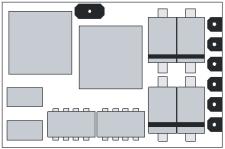
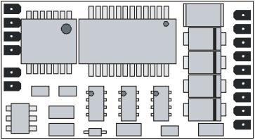
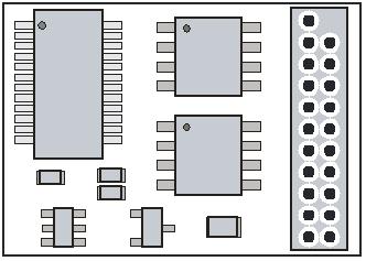
2 Loco Decoder DHP160 Loco Decoder DHP250 Loco Decoder DHP260 G1, G2 Track 1, 2 M1, M2 Motor 1, 2 LV Front light LR Rear light AUX1 AUX4 Additional functions 1 4 VS Supply voltage (+) ZVS ZCLK ZDAT GND SUSI supply voltage SUSI clock SUSI data SUSI ground 2
3 Content 1 Introduction 4 2 Safety instructions 5 3 Warranty 5 4 Support and Help 5 5 Functions 6 6 Decoder-Installation Preparation Check after the insertion Installation 8 7 Operating system SelecTRIX 1 (SX1) Functions Setup features Operation Explication of the signal-stopping section 14 8 Operating system DCC Functions Setup features Operation 22 9 Operating system SelecTRIX 2 (SX2) Functions Setup features Operation 30 Supplement 1 31 Supplement
4 Specifications Dimensions [mm] Total load Maximum motor current Maximum operating voltage Function outputs light: LV, LR Function output AUX1 Function outputs AUX2, AUX3, AUX4 SUSI interface DHP160 DHP250 DHP260 14,2 x 9,2 x 2,0 1,0 A 1,0 A 25 V each 300 ma 300 ma not available not available 23,3 x 12,9 x 2,7 1,5 A 1,5 A 25 V each 300 ma 300 ma je 1,0 A available 22,2 x 15,7 x 5,7 2,0 A 2,0 A 25 V each 300 ma 300 ma je 1,0 A available Connection options Without connection wires With ribbon cable for interface per NEM651 With connecting cable for interface per NEM652 With connection wires 21-pin connector for direct plug DHP160 DHP161 DHP163 DHP250 DHP252 DHP253 DHP260 1 Introduction The locomotive decoder DH05A and DH10A are compatible with the protocols of SelecTRIX Standard SX1 / SX2 as well as with NMRA-DCC-Standard. They can be controlled by every central control unit working with one of these data formats. They can be used for normal direct current motors as well as for coreless motors. The operation on alternating current supplied layouts with switching impulse is not allowed. The impulse excitation will destroy the decoder. 4
5 2 Safety instructions This product is not suitable for children under 14 years! It might be swallowed by children under 3 years! An improper use involves a risk of injury due to sharp edges and points. 3 Warranty The functioning of every decoder is fully tested before delivery. The warranty period is 2 years from the date of purchase. Should a failure occur during this period please contact the dealer where you purchased the decoder respectively directly the producer Doehler & Haass. 4 Support and Help In case you have any problems or questions, please contact us by under the address doehler-haass@t-online.de Normally you will get an answer within a few days. 5
6 5 Functions Operation can be controlled either by conventional DC command stations or by digital central units supporting the formats SelecTRIX 1 and 2 or NMRA-DCC Automatically switchover from conventional DC to digital operation In case of digital operation the last programmed system will be activated (no automatically switchover!) SelecTRIX 1 31 speed steps, 100 addresses SelecTRIX speed steps, addresses, 16 additional functions DCC Short addresses (1-127), long addresses ( ), with 14, 28, 126 speed steps Load compensation state of the art, that way an especially smooth regulation behavior Various regulation variants for an optimal adaptation to the motor 127 internal speed steps Block system operation by simple diodes (digital operating system) Light and function output AUX1 can be dimmed and activated analogically Function outputs AUX2, AUX3 and AUX4 (only if available) can activated analogically Shunting gear Electronic interchange ability of motor, lighting and track connections All function outputs freely programmable Thermal protection, insulation Reset function for DCC and SX2 Decoder can be updated: The update can be executed on the incorporated decoder when the loco is standing on the track (no need to open the engine, the SW-Download can be downloaded from the Internet cost free) 6
7 6 Decoder-Installation 6.1 Preparation Check if the locomotive is in perfect running order electrically and mechanically, prior to any mounting work. Defects and dirt must be eliminated first. Pay attention to the instructions of the locomotive producer. Only locomotives running smoothly in analogue mode, should be equipped with a digital decoder. New locomotives should be run in at least 30 minutes in each direction of travel. Before you start, insulate the motor and all its terminals completely against track connections (chassis, collector slipper, etc.). Both motor connections must be disconnected from the ground! Further on, all condensers have to be removed, particularly those associated with the connections of light and motor. Fix the decoder with a double sided adhesive tape. 6.2 Check after the insertion The first test should be executed in the programming mode (e.g. by reading out the address). In case of an incorrect feedback (confirmation signal) to the central unit ("error"), please check again the correct assignment of the connections respectively if the motor is really disconnected from the chassis electrically. 7
8 6.3 Installation There are two variants to connect the decoder: 1 In case your locomotive is equipped with an interface (NEM 651), you should take the decoder DHP161. They have already the appropriate connections for this plug. Shorten the ribbon cable up to approximately 5 mm and remove the rest of the insulation. The decoder can be inserted into the interface without any problem now. 2 In case your locomotive is equipped with an interface (NEM 652), you should take the decoder DHP252. They have already the appropriate connections for this plug. The decoder can be inserted into the interface without any problem now. 3 In case your locomotive is equipped with a 21-pin interface, you should take the decoder DHP260. They have already the appropriate connections for this plug. The decoder can be inserted into the interface without any problem now. 4 If the locomotive is not equipped with an interface jack, the decoder must be wired up individually. For this purpose you should use decoder with flexible wires (DHP163 respectively DHP253). 5 The decoder DHP160 respectively DHP250 should be used by experienced model railroaders only as the connection wires must be soldered directly onto the decoder. 8
9 Connect the decoder wires accordingly to the following diagram: red wire black wire orange wire gray wire white wire yellow wire green wire violet wire blue wire with the right track wire (G1) with the left track wire (G2) with the motor wire, which was connected to the right track (M1) with the motor wire, which was connected to the left track (M2) with the front light (LV) with the rear light (LR) function output AUX1 (only DHP252 and DHP253) function output AUX2 (only DHP253) supply voltage up to 25 volts (+VS) (only DHP252 and DHP253) In addition for SUSI interface (only if available): red wire blue wire gray wire black wire SUSI supply voltage (ZVS) SUSI clock (ZCLK) SUSI data (ZDAT) SUSI ground (GND) 9
.")
10 Function outputs: The function outputs AUX1, AUX2, AUX3 and AUX4 (only if available) are on the edge of the decoder and must be connected to the consumers with individual wires (see Illustration, page 2). Notice: In case of an incorrect wiring of motor, lighting and track, there is no need to solder off the wires as the assignment can be interchanged electronically by programming (see adjustment options of the respective operating system). 10
11 7 Operating system SelecTRIX 1 (SX1) 7.1 Functions Speed steps 31 Speed steps (internal) 127 Front light / rear light Additional functions 1, 2 or 4 Additional channel available (Loco address + 1) with 8 additional functions 7.2 Setup features All locomotive parameters can be varied by programming freely at any time. Please, take the information concerning the programming from the instructions of your programming device. Basic setups Loco address (01) Velocity 1 7 (5) Acceleration / Deceleration 1 7 (4) Impulse width (duration) 1 4 (2) Signal-stopping section 1 / 2 parts (1) 11
12 Extended setups Interchange of connections (V) 0 7 (4) Activation of AFB and additional channel (A) 1 6 (1) Motor regulation variant (I) 1 4 (3) AFB ("Automatische Fahr-/Bremssteuerung") = Automatically acceleration / deceleration control Interchange of connections 0 7 (4) Interchange motor connections 1 Interchange light connections 2 Interchange track connections 4 Activation of AFB and additional channel Function With AFB Without AFB Without additional channel 1 2 With ZK*) without function mapping 3 4 With ZK*) with function mapping 5 6 *) the additional channel ZK ("Zusatzkanal") has always the address: Loco address + 1 Motor regulation variant 1 4 User defined by par056 ff. 1 Hard 2 Soft 3 Very soft 4 12
13 Reading out the extended characteristic values is executed by the entry of the character sequence and a subsequently push on the programming key. Writing of the extended characteristic values is executed by the entry of the character sequence 00=VAI and a subsequently push on the programming key. Notice: Coreless motors should be operated with regulation variant 4 and pulse width 1. Damages due to incorrect adjustments are excluded from the warranty. Caution! Reading out and entering extended characteristic values overwrites the default-values of the decoder. In case you have varied the extended characteristic values, the default characteristic values of the decoder must be entered anew. 13
14 7.3 Operation Put the locomotive on the programming track and read out the programming parameters of the decoder. The default value should be Program the desired locomotive address and start running the locomotive keeping the other parameter values. After the first check you can vary the parameters of the engine freely according to your requirements. In case your programming device indicates "error", please check again the correct wiring of the locomotive and pay attention to the wiring instructions of the programming track. Never put such a locomotive into operation! 7.4 Explication of the signal-stopping section One-part signal-stopping section: In front of the signal one track section is controlled by a diode. The decoder must be programmed on one-part stopping section (-). The locomotive will be braked to a halt. Two-part signal-stopping section: In front of the signal there are two track sections. The first one is controlled by a diode and the locomotive will be braked down to internal speed step 3 in this section. The second one is without supply and the locomotive will stop just in front of the signal. The decoder must be programmed on two-part stopping section (=). 14
15 8 Operating system DCC 8.1 Functions Short addresses Long addresses Speed steps 14, 28, 126 Speed steps (internal) 127 Front light / rear light (can be dimmed) Additional function AUX1 (can be dimmed) Additional functions AUX2, AUX3, AUX4 (not DHP160) Operation with break diodes yes Operation with break generators yes Consist mode yes Full NMRA conform yes Programming on the main (POM) yes 8.2 Setup features The characteristics of a locomotive operated in the DCC-operating mode can be varied by programming the configuration variables (CV) freely at any time. The programming procedure is described in the instructions of your programming device. Notice: In case the speed steps programmed on the decoder differ from those of the control device, malfunctions may occur. Please pay attention to the respective information concerning your digital system. 15
16 List of supported CV: CV Name Definition Range Standard 01 Short address Starting voltage Reserved 03 Acceleration time The value corresponds to the time in seconds from start to maximum speed 04 Deceleration time The value corresponds to the time in seconds from maximum speed to stop Maximum speed See supplement Version number Version number 08 Manufacturer identification 97 = Doehler & Haass Decoder Reset by "8" 09 Motor frequency 0 = 32 khz, 2 = low frequency 13 Analog mode F1 F8 Bit Function Value 0 F1 1 1 F2 2 2 F3 4 3 F4 8 4 F F F F ,
17 14 Analog mode FL, F9 F12 Bit Function Value 0 FL (f) 1 1 FL (r) 2 2 F9 4 3 F F F Long address CV17 contains the most significant byte, CV18 contains the least significant byte, Only if activated by CV29 19 Consist address Several compound locos run under this address. 0 = deactivated Value = inverse direction 21 Consist mode F1 F8 Bit Function Value 0 F1 1 1 F2 2 2 F3 4 3 F4 8 4 F F F F
18 22 Consist mode FL, F9 F12 0 FL (f) FL (r) 2 2 F9 4 3 F F F Configuration register Various adjustments Bit Function 0 Inverse direction /126 speed steps 2 Analog operation permitted Long address by CV17/ Function mapping F0(f) See supplement Function mapping F0(r) See supplement Function mapping F1(f+r) See supplement If CV35 is written, CV47 will be set to the same value 36 Function mapping F2(f+r) See supplement If CV36 is written, CV64 will be set to the same value 37 Function mapping F3 See supplement Function mapping F4 See supplement Function mapping F5 See supplement
19 40 Function mapping F6 See supplement Function mapping F7 See supplement Function mapping F8 See supplement Function mapping F9 See supplement Function mapping F10 See supplement Function mapping F11 See supplement Function mapping F12 See supplement Function mapping F1(r) See supplement In case CV47 should have another value as CV35, you have to set CV35 first and then CV47 48 Characteristic diagram Response curve 0 = linear 7 = logarithmic See supplement 2 49 Impulse with 0 = 1 ms 1 = 2 ms 2 = 4 ms 3 = 8 ms 50 Regulation variant 0 = user defined by CV56 ff. 1 = Hard 2 = Soft 3 = Very Soft 51 Interchange of connections Bit Function Value 0 Motor connections 1 1 Light connections 2 2 Track connections
20 52 Dimming light "normal" 0 = off 31 = full brightness Dimming light "alternative" 0 = off 31 = full brightness Dimming AUX1 0 = off 31 = full brightness Dimming AUX2 Reserved 56 Motor proportional controller Only if activated by CV50 = Motor integral controller Only if activated by CV50 = Motor measurement period Only if activated by CV50 = Motor impulse width Only if activated by CV50 = Signal-stopping section 1 or 2 0, Shunting gear speed Shunting gear deceleration See CV Start delay speed step Function mapping F2(r) See supplement In case CV64 should have another value as CV36, you have to set CV36 first and then CV User identifier User identifier Preclusion for LV Bit 0 = F1 to bit 7 = F Preclusion for LR See CV Preclusion for AUX1 See CV Preclusion for AUX2 See CV Timer for clear AUX1 Each 100 ms, 0 = deactivated Timer for clear AUX2 Each 100 ms, 0 = deactivated Timer for clear AUX3 Each 100 ms, 0 = deactivated Timer for clear AUX4 Each 100 ms, 0 = deactivated
21 All configuration variables except for CV01, CV17 and CV18 (= locomotive addresses) can be accessed during operation on your layout (POM / programming on the main). 21
22 8.3 Operation Put the locomotive on the programming track and read out the short locomotive address of the decoder (CV 01). The default value should be 3. Program the desired locomotive address and start running the locomotive keeping the other adjustment values. After the first check you can vary the parameters of the engine freely according to your requirements. In case your programming device indicates "error", please check again the correct wiring of the locomotive and pay attention to the wiring instructions of the programming track. Never put such a locomotive into operation! Notice: Block section operation in the DC current operating mode is not possible with the factory settings. In case you want this option, you must set CV29 bit 2 to "1". 22
23 9 Operating system SelecTRIX 2 (SX2) 9.1 Functions Speed steps 127 Speed steps (internal) 127 Front light / rear light (can be dimmed) Additional function AUX1 (can be dimmed) Additional functions AUX2, AUX3, AUX4 (not DHP160) Operation with break diodes yes Programming on the main (POM) yes 9.2 Setup features The characteristics of a locomotive operated in the SX2-operating mode can be varied by programming the parameters (par) freely at any time. The parameter-programming procedure is described in the instructions of your programming device. 23
24 List of supported parameters: par Name Definition Range Standard 001 Loco address unit position Loco address hundred position Loco address for SX1 If > 111 deactivated Additional channel 1 for SX1 Functions F1 F Additional channel 2 for SX1 Functions F9 F Loco address output Activated = 1 0, Effectiveness additional channels 0 = relative: 0, 1 0 Additional 1 = par003 + par004 Additional 2 = par003 + par005 1 = absolute 008 Consist address unit position Reserved 009 Consist address hundred position Reserved 011 Acceleration time The value corresponds to the time in seconds from start to maximum speed Deceleration time See par Maximum speed See supplement Starting voltage Reserved 016 Start delay speed step 1 Each 0,1 sec Delay between receive of speed step 1 and start for the SUSI interface Shunting gear speed See supplement
25 019 Shunting gear deceleration See par Signal-stopping section 1 or 2 0, Consist mode F1 F8 Reserved 023 Consist mode FL, F9 F12 Reserved 024 Preclusion for LV Bit 0 = F1 to bit 7 = F Preclusion for LR See par Preclusion for AUX1 See par Preclusion for AUX2 See par Analog mode F1 F8 Bit Function Value F1 1 1 F2 2 2 F3 4 3 F4 8 4 F F F F Analog mode FL, F9 F12 Bit Function Value FL (f) 1 1 FL (r) 2 2 F9 4 3 F F F Interchange of track connections 0 = normal, 1 = inversed 0, Interchange of motor connections 0 = normal, 1 = inversed 0, Interchange of light connections 0 = normal, 1 = inversed 0,
26 041 Operating system Occurs during the programming automatically: 1, 2, 4 2 Bit System Value 0 SX1 1 1 DCC 2 2 SX Characteristic diagram Response curve = linear 7 = logarithmic See supplement Regulation variant 0 = user defined by par056 ff = Hard 2 = Soft 3 = Very Soft 053 Impulse width 0 = 1 ms = 2 ms 2 = 4 ms 3 = 8 ms 054 Motor frequency 0 = 32 khz, 0, = low frequency 056 Motor proportional controller Only if activated by par052 = Motor integral controller Only if activated by par052 = Motor measurement period Only if activated by par052 = Motor impulse width Only if activated by par052 = Function mapping F0(f) See supplement Function mapping F0(r) See supplement
27 063 Function mapping F1(f+r) See supplement If par063 is written, par075 will be set to the same value 064 Function mapping F2(f+r) See supplement If par064 is written, par085 will be set to the same value 065 Function mapping F3 See supplement Function mapping F4 See supplement Function mapping F5 See supplement Function mapping F6 See supplement Function mapping F7 See supplement Function mapping F8 See supplement Function mapping F9 See supplement Function mapping F10 See supplement Function mapping F11 See supplement Function mapping F12 See supplement Function mapping F1(r) See supplement In case par075 should have another value as par063, you have to set par063 first and then par Timer for clear AUX1 Each 100 ms, 0 = deactivated Timer for clear AUX2 Each 100 ms, 0 = deactivated Timer for clear AUX3 Each 100 ms, 0 = deactivated Timer for clear AUX4 Each 100 ms, 0 = deactivated Dimming light "normal" 0 = off 31 = full brightness Dimming light "alternative" 0 = off 31 = full brightness
28 083 Dimming AUX1 0 = off 31 = full brightness Dimming AUX2 Reserved 085 Function mapping F2(r) See supplement In case par085 should have another value as par064, you have to set par064 first and then par User identifier User identifier Manufacturer identifier Read only: 97 = Doehler & Haass 102 Decoder identifier Read only: DHP160 = 16 DHP250 = 25 DHP260 = Version number Read only 104 Date Read only 105 Revision number Read only 28
29 All parameters except for par001 and par002 (= locomotive address) can be accessed during operation on your layout (POM / programming on the main). 29
30 9.3 Operation Put the locomotive on the programming track and read out the locomotive address of the decoder (par001+par002). The default value should be Program the desired locomotive address and start running the locomotive keeping the other parameter values. After the first check you can vary the parameters of the engine freely according to your requirements. In case your programming device indicates "error", please check again the correct wiring of the locomotive and pay attention to the wiring instructions of the programming track. Never put such a locomotive into operation! 30
31 Supplement 1 Explanation for function mapping If you want to activate a function enter the value to the corresponding output according to the following table. In case you want to activate several different functions by one and the same output you must add up their specific values. Output's values: RG ABL AUX4 AUX3 AUX2 AUX1 LR LV Value RG = Shunting gear ABL = dimmed headlights Example: Notice: F4 should activate the shunting gear and switch on the outputs LV and LR: LV=1, LR=2, RG=128: so you must enter the value 131 in CV38 par066. AUX4, AUX3 and AUX2 are not available in the decoder DHP160. Timer function (CV , par ) Value = 0 The timer is switched off (continuous operation) Value = The timer is activated, the correspondent output will be disconnected after the set time of: entered value x 0,1 sec. 31
32 Preclusion (CV , par ) This function gives you the option to deactivate a function associated to an output partly (e.g. drivers cab light in front dark), though this output is switched on (e.g. LV by function F0). Example: F0 F2 F3 A typical situation where to apply this function is the push-pull operation. The front lighting pointing at the wagons must be switched off, but the other lights must be reversed in the direction of travel (white red). switches on the light (white or red in dependency of the direction of travel) switches off the front light switches off the rear light CV par Function RG ABL AUX4 AUX3 AUX2 AUX1 LR LV F0(f) x x F0(r) x x CV par Function F8 F7 F6 F5 F4 F3 F2 F LV off x LR off x AUX1 off x AUX2 off x LV Front light white LR Rear light white AUX1 Front light red AUX2 Rear light red 32
33 Supplement 2 Characteristic diagrams Speed step characteristics *) Maximum speed characteristic Characteristic speed step diagram: Linear 0 Logarithmic 7 *) The curve 5 of the speed step characteristics corresponds with the DHL loco decoder series. 33
34 34


35 Never throw this product in the normal household waste at the end of its lifetime. Please, always use the waste disposal plant of your municipality. Not suitable for children under 36 month because of the danger of swallowing the product and of injuries due to sharp-edged parts. Nicht geeignet für Kinder unter 3 Jahren wegen der Gefahr des Verschluckens sowie der Verletzung durch scharfkantige Teile! Ne convient pas aux enfants en dessous de 36 mois. 35
36 Company stamp DOEHLER & HAASS GmbH A. Haass Eichelhäherstrasse 54 Modifications and errors excepted D München Tel. +49 (0) Version 03/
DH12A DH16A DH18A DH21A
 DH05C DH10C Doehler & Haass LOCOMOTIVE DECODER DH12A DH16A DH18A DH21A Loco Decoder DH05C Loco Decoder DH10C Loco Decoder DH12A ZVS ZCLK ZDAT AUX1 GND AUX2 LR LV G2 G1 M2 M1 LR LV G2 G1 M2 M1 ZVS ZCLK
User Manual. LokPilot V2.0 LokPilotDCC V2.0 LokPilot micro. 4th edition, August 2005
 User Manual LokPilot V2.0 LokPilotDCC V2.0 LokPilot micro 4th edition, August 2005 user manual LokPilot DCC V2.0 / LokPilot V2.0 / LokPilot micro 4th edition, 08/2005 1 content General Features... 3 LokPilot
Multi-protocol decoder with Load regulation for DC and Faulhaber motors
 Multi-protocol decoder with Load regulation for DC and Faulhaber motors Features Regulated Multi-protocol decoder for DCC, Motorola Suitable for DC and Bell armature motors up to A Quiet motor running
60942 Conversion Decoder Set Conversion Decoder Set
 60942 Conversion Decoder Set 60962 Conversion Decoder Set Table of Contents Page Using the Product as Intended 3 Contents as Delivered 3 Safety Notes 3 Technical Information 4 Functions Decoder Installation
Hatton s DCC Decoder Instructions
 Hatton s DCC Decoder Instructions Thank you for purchasing one of our Hatton s DCC decoders. Our decoders meet all NMRA DCC specifications and will give good performance out of the pack, however by using
Features. Description. Multi-protocol decoder with load regulation for DC and Faulhaber motors
 Multi-protocol decoder with load regulation for DC and Faulhaber motors Features Regulated Multi-protocol decoder for DCC, Motorola Suitable for DC and Bell armature motors up to.5a Quiet motor running
Power 3/6. Multi-Protocol Power System Booster by Uhlenbrock. Manual
 Power 3/6 Multi-Protocol Power System Booster by Uhlenbrock Manual Based on Uhlenbrock product manual 60560 (German text) rev. 03/2004. English translation and revisions provided by Modell-Zug Elektronix.
Hybrid AC Driver [GCNC-1110]
![Hybrid AC Driver [GCNC-1110]](/thumbs/86/94474371.jpg "Hybrid AC Driver [GCNC-1110]") Page 1 Installation Manual and Datasheet Page 2 Key Features Smooth and quiet operation at all speeds and extremely low motor heating Industrial grade performance for an alternating current servo motor
Page 1 Installation Manual and Datasheet Page 2 Key Features Smooth and quiet operation at all speeds and extremely low motor heating Industrial grade performance for an alternating current servo motor
Unleashing the Power of DCC
 Command Station LZ100 1 Unleashing the Power of DCC LZ100 Command Station Operations Manual Version 3.2 art. no. 20101 revised February 2001 Version 3.2 2 Command Station LZ100 Getting started To get started
Our Famous GOOF PROOF Warranty
 Our Famous GOOF PROOF Warranty TM MTC21-Pin Connector Scale Functions Function Rating Continuous/Peak HO 8 100 ma 1.3 /2.0 Amp Dimensions: 1.28 x.69 x.22 or 32.5mm x 17.5mm x 5.6mm Main Features of this
Power 7 The universal booster for almost all digital systems
 Power 7 The universal booster for almost all digital systems 1 Table of Contents 1. General Information 4 1.1 Description 4 1.2 Technical Data 4 2. Installation 5 2.1 The Connectors 5 2.2 Connection Transformer
Digitrax Sound Decoder Specification Sheet
 Digitrax Sound Decoder Specification Sheet SDN144K1E 1 Amp N Scale Mobile Decoder with SoundFX for Kato SD40-2 and similar locos Physical Size Speaker Rating Capacitor Simultaneous Voices 0.40 x 2.97 x
NEWSLETTER VOLUME 20 - NO. 6 November- December 2008 Dr. Tom Catherall, Editor
 NEWSLETTER VOLUME 20 - NO. 6 November- December 2008 Dr. Tom Catherall, Editor Märklin Digital Central Station Have you noticed the branding change from Märklin Systems to Märklin Digital with the new
HO-Scale Kato DCC Sound Conversion Kit
 Our Famous GOOF PROOF NO Questions Asked Warranty WOWKit Compatibility for HO-Scale Bowser Locomotives DS 4-4-1000 WDK-BOW-1 S-12 WDK-BOW-2 C-636 WDK-BOW-3 Included in this WOWKit: HO-Scale Kato DCC Sound
Strain gauge Measuring Amplifier GSV-1A8. Instruction manual GSV-1A8, GSV-1A8USB, GSV-1A16USB
 Strain gauge Measuring Amplifier GSV-A8 Instruction manual GSV-A8, GSV-A8USB, GSV-A6USB GSV-A8USB SubD5 (front side) GSV-A8USB M2 (front side) GSV-A6USB (rear side) GSV-A8USB K6D (front side) Version:
HO-Scale Atlas DCC Sound Conversion Kit
 Our Famous GOOF PROOF Warranty WOWKit Compatibility for HO-Scale Atlas Locomotives Master Collection: Trainman Collection: ALCO RS-1 WDK-ATL-2 ALCO RS32/36 WDK-ATL-1 ALCO C420 WDK-ATL-3 EMD GP39-2 Ph.
DCC Industry Quality Metrics
 DCC Industry Quality Metrics These quality metrics represent typical industry practice, and are used in conjunction with the NMRA Standards and Recommended Practices for Conformance and Inspection testing.
Strain gauge Measuring Amplifier GSV-1A8. Instruction manual GSV-1A8, GSV-1A8USB, GSV-1A16USB
 Strain gauge Measuring Amplifier GSV-1A8 Instruction manual GSV-1A8, GSV-1A8USB, GSV-1A16USB GSV-1A8USB SubD1 (front side) GSV-1A8USB M12 (front side) GSV-1A16USB (rear side) GSV-1A8USB K6D (front side)
TEAM DIGITAL. SRC162e Switch & Route Controller
 TEAM DIGITAL SRCe Switch & Route Controller Improving the world of DCC > DCC compatible accessory decoder > Control switches (turnouts) > Drive switch status LEDs > Drive Tortoise switch machines > configurable
DIGITAL DISPLAY. for Industry Applications. Series WAY-SSI. Key-Features:
 DIGITAL DISPLAY for Industry Applications Series WAY-SSI Key-Features: Content: Technical Data.2 Technical Drawing...2 Electrical Connection...3 Description...4 Order Code & Accessories...6 - WAY-SSI-S:
SIMPLY PRECISE USER MANUAL. ADJUSTMENT TOOL For NUMERIK JENA Encoders with Online Compensation
 USER MANUAL ADJUSTMENT TOOL For NUMERIK JENA Encoders with Online Compensation 2 Index 1. Features and Applications... 3 1.1 Functions of the ADJUSTMENT TOOL... 3 1.2 Dynamic Offset and Amplitude Control
OFP401P0189. Color Sensor. Operating Instructions
 OFP401P0189 Color Sensor Operating Instructions Last update: 23 May 2013 2 Table of contents 1. Proper Use 4 2. Safety Precautions 4 3. EC Declaration of Conformity 4 4. Technical Data 5 4.1. Connection
Electrical Interface 21MTC
 Normen Europäischer Modellbahnen Electrical Interface 2MTC NEM 660 Page von 5 Recommendation Dimensions in mm Edition 20 (replacing edition 200). Purpose of Standard This standard defines a Interface which
Please fill in the following information on the decoder manufacturer. Company Name: Manufacturer ID Code:
 LOCOMOTIVE DECODER Functional Test Report By Stan Ames NMRA Conformance and Inspection Committee Introduction The purpose of this form is to document essential test results concerning functional tests
LED Dimmer LED-08T
 Dimmer -08T General The dimmer was especially developed to control s in ground plan touch pads. For the fi rst time this device enables you to control the brightness of s between 0 and 100% so that it
TEAM DIGITAL. SMD84 Switch Machine Driver with Serial Bus
 TEAM DIGITAL SMD84 Switch Machine Driver with Serial Bus Improving the world of DCC > DCC compatible accessory decoder > Drives 8 solenoid and/or stall type machines > 8 configurable routes > 13 Individually
TEAM DIGITAL. CSCe Central Signal Controller
 TEAM DIGITAL Improving the world of DCC CSCe Central Signal Controller > Control signals on your layout > Compatible with the SHD2 > 6 inputs for sensors/switches > 6 outputs to drive LEDs > 2 outputs
TEAM DIGITAL. SRC16 Switch & Route Controller
 6 Cont. Summary of Configuration Variables CV# Function/Default Value CV# Function/Default Value 73 Route 3 Cell 7 Address Adder 0 25 Route 6 Cell 4 Address Adder 0 74 Route 3 Cell 8 Address 0 26 Route
Manual. Polaron SMPS Watt power supply for chargers. No. S2024. Copyright Graupner/SJ GmbH
 EN Manual Polaron SMPS 1500 1500 Watt power supply for chargers Copyright Graupner/SJ GmbH No. S2024 Index Introduction... 3 Service Centre... 3 Declaration of conformity... 3 Intended use... 4 Package
GSV-1A4 M12/2 M12/2. Highlights
 GSV-1A4 M12/2 M12/2 Highlights Input sensitivity: 2mV/V; 4mV/V, 2 mv/v, 1mV/V, 0.5mV/V configurable via jumpers Output signals ±10V AND 12mA+-8mA on 15 pin Sub-D Integrated half and quarter bridge completion
CBM-103FN/FP Circuit Board
 CBM-103FN/FP Circuit Board Features New driver card specifically designed for the new KE series Power Moller family Adjustable acceleration and deceleration time (0 to 2.5s) Stable speed operation Manual
PCL451. Manual Preset Indexer. User s Guide E Landon Drive, Anaheim, CA
 PCL451 Manual Preset Indexer User s Guide A N A H E I M A U T O M A T I O N 4985 E Landon Drive, Anaheim, CA 92807 e-mail: info@anaheimautomation.com (714) 992-6990 fax: (714) 992-0471 website: www.anaheimautomation.com
User Manual. LokSound V3.0 / V3.5 LokSoundXL LokSound micro. 4 th edition, August user manual LokSound / LokSoundXL V3.5, 4th edition, 08/2005 1
 User Manual LokSound V3.0 / V3.5 LokSoundXL LokSound micro 4 th edition, August 2005 user manual LokSound / LokSoundXL V3.5, 4th edition, 08/2005 1 524xx_LokSound_V35_ESUKG_US_Betriebsanleitung_Auflage_IV.pmd
TEAM DIGITAL. BlocD8 High Density Block Detector. BlocD8
 TEAM DIGITAL Improving the world of DCC BlocD8 High Density Block Detector > 8 block detectors > Electrical isolation from the track > No track voltage drop > LED indicator for each block > 8 outputs for
Digitrax Sound Decoder Specification Sheet
 Digitrax Sound Decoder Specification Sheet SDN144PS 1 Amp N Scale Mobile Sound/Motor/Function Decoder with SoundFX Physical Size 1.22 x 0.4 x 0.164 Current Rating 1.0/2.0 Amps 31mm x 10.27mm x 4.16mm Speaker
Mini Panel. Accy and Macro Controller. Build the kind of control panels you ve always wanted without complicated wiring!
 Mini Panel Accy and Macro Controller Dimensions: 3.0" x.70" (8 x 69 mm) Revision.00 $49.95 Build the kind of control panels you ve always wanted without complicated wiring! Use one button to control multiple
OPT2011. High-performance distance sensor. Operating Instructions
 OPT2011 High-performance distance sensor Operating Instructions Status: 15/07/2013 2 Table of Contents 1. Use for Intended Purpose 4 2. Safety Precautions 4 2.1. Safety Precautions 4 2.2. Laser/LED warning
Installation instructions Diagnostic electronics for vibration sensors VSE / / 2007
 Installation instructions Diagnostic electronics for vibration sensors UK VSE00 70406 / 00 07 / 2007 Contents Safety instructions 3 Function and features 4 Mounting 4 Mounting of the sensors 5 Electrical
ADC7520 SERIES. 1600W Battery Chargers and Power Supplies
 ADC7520 SERIES 1600W Battery Chargers and Power Supplies Wide output adjustment range 0 72VDC Analog control by external 0-5VDC voltage Temp.comp charging, sense as on option Power fail relay alarm Master-Slave
The Universal Translator
 Universal Translator - Application and Installation! 1 The Universal Translator The Universal Translator! 1 Examples and Guidelines! 2 Application Notes! 4 Installing and Troubleshooting Your Translator!
USER MANUAL. LED IP Ribbon. ~Horizontal~ Keep this manual for future needs! Copyright Reproduction prohibited!
 USER MANUAL LED IP Ribbon ~Horizontal~ Keep this manual for future needs! Copyright Reproduction prohibited! MULTI-LANGUAGE-INSTRUCTIONS Inhaltsverzeichnis Table of contents INTRODUCTION... 7 SAFETY INSTRUCTIONS...
DPX-620III 6-Ch. dimmer pack. user manual
 DPX-620III 6-Ch. dimmer pack user manual Musikhaus Thomann Thomann GmbH Hans-Thomann-Straße 1 96138 Burgebrach Germany Telephone: +49 (0) 9546 9223-0 E-mail: info@thomann.de Internet: www.thomann.de 28.08.2017,
Drive Technology \ Drive Automation \ System Integration \ Services. Manual. Electronic Motor DRC Functional Safety
 Drive Technology \ Drive Automation \ System Integration \ Services Manual Electronic Motor DRC Functional Safety Edition 02/2012 19376812 / EN SEW-EURODRIVE Driving the world Contents Contents 1 General
Operating instructions. Speed monitor D / / 2014
 Operating instructions Speed monitor D200 80005257 / 00 05 / 2014 Contents 1 Preliminary note...4 1.1 Symbols used...4 1.2 Warning signs used...4 2 Safety instructions...5 2.1 General...5 2.2 Target group...5
precimodels DCC Uncoupler Conversion Kit HO scale Installation Manual
 precimodels DCC Uncoupler Conversion Kit HO scale Installation anual User's anual Table of Contents 1.KIT CONTENTS... 2 2.INTRODUCTION... 2 3.ECHANICAL INSTALLATION... 3 3.1.Find the right mounting position...3
net4more IP connected lighting system net4more Driver net4more driver DC 30W mA un:c LED Driver for net4more systems
 net4more IP connected lighting system net4more driver DC 3W 35-7mA LED Driver for net4more systems Product description interface dimmable Adjustable output current between 35 and 7 ma Output voltage range
SINCOS. Linear Stepper Motor Power Stage. Manual 2066-A006 GB
 SINCOS Linear Stepper Motor Power Stage Manual 2066-A006 GB phytron SINCOS Linear Stepper Motor Power Stage for Bipolar Control Mode Manual 2066-A006 GB Manual SINCOS 2002 All rights with: Phytron GmbH
INSTRUCTION MANUAL. Tel. Fax. +49 (0) 4154 / (0) 4154 / Internet.
 4154 / (0) 4154 / Internet.") INSTRUCTION MANUAL Tel. Fax. E-mail Internet Address +49 (0) 4154 / 80 83-0 +49 (0) 4154 / 80 83-20 info@camos-multimedia.com www.camos-multimedia.com CAMOS Europe GmbH Carl-Zeiss-Str. 3 D-22946 Trittau
INSTRUCTION MANUAL Tel. Fax. E-mail Internet Address +49 (0) 4154 / 80 83-0 +49 (0) 4154 / 80 83-20 info@camos-multimedia.com www.camos-multimedia.com CAMOS Europe GmbH Carl-Zeiss-Str. 3 D-22946 Trittau
Mitsubishi Electric Automation Instruction Manual FR-A5AC-01
 Mitsubishi Electric Automation Instruction Manual FR-A5AC-01 AC Input Interface Option Unit NOTE: CAUTION: WARNING: NOTES, CAUTIONS AND WARNINGS Notes are used to provide additional detail about a procedure.
SAFETY PRECAUTIONS CAUTION WARNING CAUTION. Thank you for purchasing ig5a Series Profibus Communication Module
 SAFETY PRECAUTIONS Thank you for purchasing ig5a Series Profibus Communication Module SAFETY PRECAUTIONS Always follow safety instructions to prevent accidents and potential hazards from occurring. Safety
GREISINGER electronic GmbH. D Regenstauf, Hans-Sachs-Straße 26. T-Logg 120 W -... T-Logg 120 K -...
 E39.0.1X.6C-01 Data logger for standard signals as of version 1.0 Operating Instruction T-Logg 120... T-Logg 120 W -... T-Logg 120 K -... GREISINGER electronic GmbH D - 93128 Regenstauf, Hans-Sachs-Straße
D115 The Fast Optimal Servo Amplifier For Brush, Brushless, Voice Coil Servo Motors
 D115 The Fast Optimal Servo Amplifier For Brush, Brushless, Voice Coil Servo Motors Ron Boe 5/15/2014 This user guide details the servo drives capabilities and physical interfaces. Users will be able to
HO-Scale Athearn DCC Sound Conversion Kit
 Our Famous GOOF PROOF NO WOWKit Compatibility for HO-Scale Athearn Locomotives Genesis Collection: Ready-To-Run Collection: GE ES44AC GEVO WDK-ATH-1 GE AC4400CW WDK-ATH-5 EMD F2 / F3 / F7 / F9 GE AMD103/P40/P42
SRC8 Switch & Route Controller
 12 CV# Function/Default Value CV# Function/Default Value 11 Group 3 Alt Address 0 56 Route 4 Cell 8 0 12 Group 4 Alt Address 0 57 Route 5 Switch State 0 13 Group 5 Alt Address 0 58 Route 5 Cell Address
Manual. Panelmeter EX20xx, EX30xx
 www.bue.de Manual Panelmeter EX20xx, EX30xx EN Attention! Read this first! Read through the Instructions manual carefully. The warranty becomes null and void if damage or injury results from non-compliance
Operating Instructions for Low Volume Rotating Vane Flow Meter. Model: DPL-1P... DPL-1V... DPL-1E...
 Operating Instructions for Low Volume Rotating Vane Flow Meter Model: DPL-1P... DPL-1V... DPL-1E... 1. Contents 1. Contents... 2 2. Note... 3 3. Instrument Inspection... 3 4. Regulation Use... 3 5. Operating
Working model decoder
 Working model decoder 67 9 Description The stationary Decoder, for installing in working models (e.g. model crane), has two outputs for motors and four additional switch outputs. The working model decoder
GREISINGER electronic GmbH D Regenstauf, Hans-Sachs-Straße 26
 E39.0.31.6C-02 Data logger for humidity temperature as of version V1.0 Operating Manual T-Logg 160 GREISINGER electronic GmbH D - 93128 Regenstauf, Hans-Sachs-Straße 26 +49 (0) 9402 / 9383-0 +49 (0) 9402
Drive Technology \ Drive Automation \ System Integration \ Services. Manual. Control Cabinet Inverter MOVITRAC B Functional Safety
 Drive Technology \ Drive Automation \ System Integration \ Services Manual Control Cabinet Inverter MOVITRAC B Functional Safety Edition 05/2009 16811216 / EN SEW-EURODRIVE Driving the world Content Content
Vector Beam White. User Manual. Order code: LEDJ265
 Vector Beam White User Manual Order code: LEDJ265 Safety advice WARNING FOR YOUR OWN SAFETY, PLEASE READ THIS USER MANUAL CAREFULLY BEFORE YOUR INITIAL START-UP! Before your initial start-up, please make
Digitrax Sound Decoder Specification Sheet
 Digitrax Sound Decoder Specification Sheet SFX0416 1 Amp N or HO SoundFX & Function Decoder Physical Size 1.22 x 0.42 x 0.21 Current Rating 1.0 Amp 31mm x 10.6mm x 5.3mm Speaker 8 Ohm Speaker Size 28mm
Alu HEX Par 64. (12 x 12W six-colour LEDs RGBWAUV) User Manual. Order code: ELUM114
 User Manual. Order code: ELUM114") Alu HEX Par 64 (12 x 12W six-colour LEDs RGBWAUV) User Manual Order code: ELUM114 Safety advice WARNING FOR YOUR OWN SAFETY, PLEASE READ THIS USER MANUAL CARE- FULLY BEFORE YOUR INITIAL START-UP! Before
Alu HEX Par 64 (12 x 12W six-colour LEDs RGBWAUV) User Manual Order code: ELUM114 Safety advice WARNING FOR YOUR OWN SAFETY, PLEASE READ THIS USER MANUAL CARE- FULLY BEFORE YOUR INITIAL START-UP! Before
OPERATING MANUAL. DMX Demultiplexer 3006D-RDM Mk1
 last edited: 16-03-16 OPERATING MANUAL DMX Demultiplexer 3006D-RDM Mk1 (C) SOUNDLIGHT 1995-2016 * ALL RIGHTS RESERVED * NO PART OF THIS MANUAL MAY BE REPRODUCED, DUPLICATED OR USED COMMERCIALLY WITHOUT
What s in the Box? REAR VIEW SAFETY
 TM 1 What s in the Box? 1 Full HD Color Infra-red Weather Proof Camera 1 Full HD 7" TFT LCD Color Monitor w/monitor Mount 1 Power Harness 1 66 Camera Cable 1 Power Connection Wire 1 Screw Kit for installation
SDXN146K1E SoundFX Drop in Mobile Decoder for Kato N Scale SD40-2 and similar Locomotives 8 Selectable Steam & Diesel Sound Schemes Included
 Features: Complete Train Control Run Your Trains, Not Your Track! SDXN146K1E SoundFX Drop in Mobile Decoder for Kato N Scale SD40-2 and similar Locomotives 8 Selectable Steam & Diesel Sound Schemes Included
Operating Instructions for Low Volume Rotating Vane Flow Meter. Model: DPL-1P... DPL-1V... DPL-1E...
 Operating Instructions for Low Volume Rotating Vane Flow Meter Model: DPL-1P... DPL-1V... DPL-1E... 1. Contents 1. Contents... 2 2. Note... 3 3. Instrument Inspection... 3 4. Regulation Use... 3 5. Operating
Functions. Requirements
 ElMod 3to Truck Module Detailed installation instructions and user manual Before starting the installation always carefully read and comply with all these instructions. We congratulate you on your purchase
English. Operating manual. Universal transmitter UT125. Save for later reference. Companies / brands of GHM
 English Operating manual Universal transmitter UT125 Companies / brands of GHM www.ghm-messtechnik.de Save for later reference. Table of contents page 1. Intended use (areas of application)... 3 1.1 Safety
LED Driver Linear / area dimming
 Driver LC 75W 100 400mA 1-10V lp EXC EXCITE series Product description Built-in constant current LED Driver Dimmable via 1... 10 V interface Dimming range 10 100 % (Depending on load, for details refer
Operating Instruction for Turbine-wheel Flow Meter. Model: DRS
 Operating Instruction for Turbine-wheel Flow Meter Model: DRS . Contents. Contents... 2 2. Note... 3 3. Instrument Inspection... 3 4. Regulation Use... 3 5. Operating Principle... 4 6. Mechanical Connection...
INSTRUCTIONMANUAL. 24V motor control device for DIN-rail mounting
 INSTRUCTIONMANUAL 24V motor control device for DIN-rail mounting Product group: shutters, sliding windows, sliding shutters Version: 1.0 Language: english Orig. Language: german (deutsch) Document: ------
DT1102 V (PS) Fully Configurable Galvanic Isolator. Operating Instructions
 Fully Configurable Galvanic Isolator. Operating Instructions") (PS) Fully Configurable Galvanic Isolator Operating Instructions Contents 1. About this document...4 1.1. Function... 4 1.2. Target group... 4 1.3. Symbolism used... 4 2. For your safety...5 2.1. Authorized
(PS) Fully Configurable Galvanic Isolator Operating Instructions Contents 1. About this document...4 1.1. Function... 4 1.2. Target group... 4 1.3. Symbolism used... 4 2. For your safety...5 2.1. Authorized
Electric Version 1. Programming Guide
 Electric Version 1 Programming Guide 3-1-2018 This manual covers the setup and configuration of the Sound Components of the WOWSound Electric decoder. All NMRA, Lighting, and Motor Control programming
INSTRUCTION MANUAL. * Design and Specifications are subject to change without notice. ver. 1.0 PRINTED IN KOREA
 INSTRUCTION MANUAL * Design and Specifications are subject to change without notice. ver. 1.0 PRINTED IN KOREA INSTRUCTION MANUAL Thank you for purchasing this product. For proper usage and application,
PQ V ac. CONTROL PANEL 230V FOR ROLLING SHUTTERS Instructions Manual. Control panel for electric rolling shutters 230Vac TECHNICAL FEATURES
 CONTROL PANEL 230V FOR ROLLING SHUTTERS Instructions Manual Q45 230V ac Control panel for electric rolling shutters 230Vac Built-in radio receiver 433Mhz Adjustable pause time for automatic closing function
Flow Sensor SONOFLOW CO.55
 Flow Sensor SONOFLOW CO.55 Operating Manual Device: Model: Type: Flow Sensor SONOFLOW CO.55 Manufacturer: SONOTEC Ultraschallsensorik Halle GmbH Nauendorfer Str. 2 06112 Halle (Saale), Germany Phone: +49
Operating instructions. Switching amplifier DN0210 DN / / 2015
 Operating instructions Switching amplifier DN0210 DN0220 UK 80011079 / 00 01 / 2015 Contents 1 Preliminary note...4 1.1 Symbols used...4 1.2 Warning signs used...4 2 Safety instructions...5 2.1 General...5
PF LED Profile. User Manual
 PF LED Profile User Manual Order codes: ELUM094-100W 3200K WW Version ELUM095-100W 6000K CW Version ELUM096-150W 3200K WW Version ELUM097-150W 6000K CW Version Safety advice WARNING FOR YOUR OWN SAFETY,
COMFORT CONTROL CENTER SERVICE INSTRUCTIONS
 USA SERVICE OFFICE Dometic Corporation 2320 Industrial Parkway Elkhart, IN 46516 574-294-2511 CANADA Dometic Corporation 46 Zatonski, Unit 3 Brantford, ON N3T 5L8 CANADA 519-720-9578 For Service Center
UV Power Flood. User Manual. Order code: EQLED029
 UV Power Flood User Manual Order code: EQLED029 Safety advice WARNING FOR YOUR OWN SAFETY, PLEASE READ THIS USER MANUAL CARE- FULLY BEFORE YOUR INITIAL START-UP! Before your initial start-up, please make
OPERATING MANUAL. DMX Multiplexer 3112A-H Mk3
 last updated: 16.05.14 OPERATING MANUAL DMX Multiplexer 3112A-H Mk3 (C) SOUNDLIGHT 1996-2015 * ALL RIGHTS RESERVED * NO PART OF THIS MANUAL MAY BE REPRODUCED, DUPLICATED OR USED COMMERCIALLY WITHOUT THE
Gauge Mount Radio PRIMARY FEATURES. Marine & Powersports Bluetooth Source Units
 R MUSIC.DEFINED. Gauge Mount Radio Marine & Powersports Bluetooth Source Units Thank you for choosing the MB Quart Nautic GMR Marine & Powersports Source Units. With proper installation, you are on the
BB-303 Manual Baseboard for TMCM-303
 BB-303 Manual Baseboard for TMCM-303 Trinamic Motion Control GmbH & Co. KG Sternstraße 67 D 20357 Hamburg, Germany http://www.trinamic.com BB-303 Manual (V1.04 / Jul 9th, 2007) 2 Contents 1 Features...
OptiStep Hardware Manual
 OptiStep Hardware Manual Document Revision D4 May 16, 2018 MICROKINETICS CORPORATION 3380 Town Point Drive Suite 330 Kennesaw, GA 30144 Tel: (770) 422-7845 Fax: (770) 422-7854 www.microkinetics.com Table
OPERATING MANUAL. DMX / PWM Decoder 3633PWM-H Mk1 RDM
 last updated: 15-03-04 OPERATING MANUAL DMX / PWM Decoder 3633PWM-H Mk1 RDM (C) SOUNDLIGHT 1996-2015 * ALL RIGHTS RESERVED * NO PART OF THIS MANUAL MAY BE REPRODUCED, DUPLICATED OR USED COMMERCIALLY WITHOUT
Intense 9P10 RGBWA LED Slim Par
 Intense 9P10 RGBWA LED Slim Par 9 x 10W five-colour LEDs (RGBWA) User Manual Convection cooled, no fan! Order code: LEDJ254 (Black Housing) LEDJ254Z (White Housing) Safety advice WARNING FOR YOUR OWN SAFETY,
Z58-6XX SERIES 6 Digits Universal Position Indicator for incremental or absolute encoders
 Z58-6XX SERIES 6 Digits Universal Position Indicator for incremental or absolute encoders connectable to incremental- or absolute encoders (FMAX, FEMAX, EMAX) approved standard functions (e.g. pulse scaling,
Series B9 and C9 Electronic Metering Pumps. Instruction Manual. Manual No : 1796 Rev. : D Rev. Date : 11/2015
 Series B9 and C9 Electronic Metering Pumps Manual No : 1796 Rev. : D Rev. Date : 11/2015 sales@novatech-usa.com www.novatech-usa.com Tel: (866) 433-6682 Fax: (866) 433-6684 Tel: (281) 359-8538 Fax: (281)
HEX Par 9 MKII. Exterior Fixture User Manual. Order code: LEDJ226
 HEX Par 9 MKII Exterior Fixture User Manual Order code: LEDJ226 Safety advice WARNING FOR YOUR OWN SAFETY, PLEASE READ THIS USER MANUAL CARE- FULLY BEFORE YOUR INITIAL START-UP! Before your initial start-up,
MDM 011-Z1 Regen Resistor
 MDM 011-Z1 Regen Resistor Date of creation: 10.04.2017 Version date: 10.04.2017 Article number: 09-402-011-Z1-E Publisher: SIGMATEK GmbH & Co KG A-5112 Lamprechtshausen Tel.: 06274/4321 Fax: 06274/4321-18
HandControl. Decentralised control device for digital control EasyControl. Manual. Art.-Nr
 Decentralised control device for digital control EasyControl Art.-Nr. 25-01-111 Manual Information and tips: www. tams-online.de Warranty and service: Tams Elektronik GmbH Rupsteinstraße 10 D-30625 Hannover
LED Driver Compact fixed output
 Driver LC 100W 1100 2100mA flexc C EXC EXCITE series Product description Constant current LED Driver Dimmable via ready2mains Gateway Dimming range 15 100 % (Depending on load. For details refer to chapter
Digitrax Sound Decoder Specification Sheet
 Digitrax Sound Decoder Specification Sheet SDH164K1A 1 Amp HO Scale Mobile Decoder with SoundFX for Kato AC4400 Locos Physical Size 2.877 x.667 x.173 Current Rating 1.0/1.3 Amps (73.07mm x 16.93mm x 4.4mm
ZF LED Zoom Fresnel. User Manual
 ZF LED Zoom Fresnel User Manual Order codes: ELUM090-100W 3200K WW Version ELUM091-100W 6000K CW Version ELUM092-150W 3200K WW Version ELUM093-150W 6000K CW Version Safety advice WARNING FOR YOUR OWN SAFETY,
Analog Input and Output Options for Syringe Pumps
 Analog Input and Output Options for Syringe Pumps Installation and Operation Instructions Syringe Pumps Technical Bulletin TB03 Overview Teledyne Isco offers several options for external analog control
SDN136PS SoundFX Fits many N locomotives 2 Selectable Steam & Diesel Sound Schemes Included
 SDN136PS SoundFX Fits many N locomotives 2 Selectable Steam & Diesel Sound Schemes Included Features: Complete Train Control Run Your Trains, Not Your Track! N Scale Mobile Decoder with SoundFX Digitrax
Extension module for lighting control
 s 3 842 DESIGO RXC Extension module for lighting control Extension to the RXC30 / RXC31 / RXC38 room controller RXC40.1 RXC40.5 The RXC40 extension module is used in conjunction with an RXC30, RXC31 or
BehringerMods.com. Instructions for modification of Behringer SRC analog inputs and outputs
 BehringerMods.com Instructions for modification of Behringer SRC analog inputs and outputs The following instructions will cover the details of fully modifying a unit with analog output and analog input
LED Driver Linear / area dimming
 Driver LC 75W 100 400mA 1-10V lp EXC EXCITE series Product description Built-in constant current LED Driver Dimmable via 1... 10 V interface Dimming range 10 100 % (Depending on load. For details refer
Secured Series: Hub Plus Kit Single Door Controller Package Installation Manual
 Secured Series: Hub Plus Kit Single Door Controller Package Installation Manual This package is designed to simplify the connections to our Secured Series Hub Plus Controller. This will translate into