SIMATIC. PCS 7/505 Symbols and Faceplates. Preface, Contents. Common HMI Elements 1. Symbols 2. Tag Structures and Faceplates.
|
|
|
- Gloria Ellis
- 6 years ago
- Views:
Transcription
1 s SIMATIC PCS 7/505 Symbols and Faceplates Preface, Contents Common HMI Elements 1 Symbols 2 Tag Structures and Faceplates 3 Action Requests 4 Manual Edition 07/2006 A5E
2 Safety Guidelines This manual contains notices you have to observe in order to ensure your personal safety, as well as to prevent damage to property. The notices referring to your personal safety are highlighted in the manual by a safety alert symbol, notices referring to property damage only have no safety alert symbol. The notices shown below are graded according to the degree of danger.!!! Danger indicates that death or severe personal injury will result if proper precautions are not taken. Warning indicates that death or severe personal injury may result if proper precautions are not taken. Caution with a safety alert symbol indicates that minor personal injury can result if proper precautions are not taken. Caution without a safety alert symbol indicates that property damage can result if proper precautions are not taken. Qualified Personnel Prescribed Usage Notice indicates that an unintended result or situation can occur if the corresponding notice is not taken into account. If more than one degree of danger is present, the warning notice representing the highest degree of danger will be used. A notice warning of injury to persons with a safety alert symbol may also include a warning relating to property damage. The device/system may only be set up and used in conjunction with this documentation. Commissioning and operation of a device/system may only be performed by qualified personnel. Within the context of the safety notices in this documentation qualified persons are defined as persons who are authorized to commission, ground and label devices, systems and circuits in accordance with established safety practices and standards. Note the following:! Warning This device and its components may only be used for the applications described in the catalog or the technical description, and only in connection with devices or components from other manufacturers which have been approved or recommended by Siemens. Correct, reliable operation of the product requires proper transport, storage, positioning and assembly as well as careful operation and maintenance. Trademarks All names identified by are registered trademarks of the Siemens AG. The remaining trademarks in this publication may be trademarks whose use by third parties for their own purposes could violate the rights of the owner. Disclaimer of Liability We have reviewed the contents of this publication to ensure consistency with the hardware and software described. Since variance cannot be precluded entirely, we cannot guarantee full consistency. However, the information in this publication is reviewed regularly and any necessary corrections are included in subsequent editions. Siemens AG Automation and Drives Postfach NÜRNBERG GERMANY Copyright Siemens AG 2006 A5E Siemens AG 2006 Technical data subject to change.
3 Preface Purpose of the Manual This manual provides the information necessary to use the PCS 7/505 OS Symbols and Faceplates. Required Basic Knowledge Readers are presumed to be knowledgeable in the use of PCS 7. Where is this Manual valid? This manual is valid for the software package PCS 7/505 OS Option for V6.1. Training Centers Siemens Technical Training Center provides extensive training for all levels of plant personnel to ensure optimal performance from PCS 7 control systems. Classes include extensive hands-on activities using appropriate equipment, making the training directly and immediately applicable. On-line information is available: Siemens also offers a number of training courses to familiarize you with the SIMATIC S7 automation system. Please contact your regional training center or our central training center in D Nuremberg, Germany for details: Telephone: +49 (911) Internet: AE iii
 262 2522 or +1 (800) 333-7421 (USA only) Fax:+1 (423) 262 2289 Mail to: techsupport.sea@siemens.")
4 Preface A&D Technical Support Worldwide, available 24 hours a day: Nürnberg Johnson City Beijing United States: Johnson City, TN Worldwide: Nürnberg Asia / Australia: Beijing Technical Support and Authorization Local time: Monday to Friday 8:00 AM to 5:00 PM Telephone:+1 (423) or +1 (800) (USA only) Fax:+1 (423) Mail to: techsupport.sea@siemens.com GMT: -5:00 Technical Support 24 hours a day, 365 days a year Phone:+49 (180) Fax:+49 (180) ad.support@siemens.com GMT:+1:00 Authorization Local time: Monday to Friday 8:00 AM to 5:00 PM Phone: +49 (180) Fax: +49 (180) Mail to: ad.support@siemens.com GMT: +1:00 Technical Support and Authorization Local time: Monday to Friday 8:00 AM to 5:00 PM Phone: Fax: Mail to:ad.support.asia@siemens.com GMT:+8:00 Automation and Drives Service and Support International The languages of the SIMATIC Hotlines and the authorization hotline are generally German and English. iv AE
5 Contents 1 Common HMI Elements Common Faceplate Elements Analog Edit Dialog Box Discrete Edit Dialog Box Text Edit Dialog Box PCS 7 External Tag Count Operator Change Confirmation Synchronization and Persistance of HMI Tag Values Disabled Alarm List Symbols Symbols Tag Structures and Faceplates Tag Structures and Faceplates _AI _AO _CALC _CTR _DI _DI _DO _DO _IVAR _LOOP _MTR _MTR _RMTR _PLC _TEXT _TMR _VLV _VLV Action Requests Overview of Action Requests ACTION_REQUEST A5E v
6

7 1 Common HMI Elements 1.1 Common Faceplate Elements file contains a generic discrete I/O button and a generic analog I/O edit field. These objects can be manually copied to any user graphic. If the tag to be edited is part of a tag structure, then standard PCS 7 user authorization will be enforced. If the tag to be edited is a single tag (not part of a tag structure), no PCS 7 user authorization will be enforced since a single tag cannot be assigned to a process area for user authorization enforcement. At runtime, the discrete I/O button provides the ability to edit any existing BOOL type tag. All changes to the BOOL tag are recorded in the WinCC operators log. The tag, along with "On" and "Off" messages, and "On" and "Off" button text are configured from the object properties dialog in Graphics Designer. At runtime, the analog I/O field provides the ability to edit any existing analog tag. All changes to the analog tag are recorded in the WinCC operators log. The tag, along with range limits, and display format are configured from the object properties dialog in Graphics Designer. file also contains an example of a button that allows a trend group created with the PCS 7 Online Trend Configuration Utility to be opened up directly by name instead of selecting it from a list. The trend group name and the monitor to display the trend group on are configurable. Use the properties dialog box to configure the Mouse Action for the object. Faceplate Overview Window Key Description 1 Alarm Group Display 2 Lock/unlock messages button 3 Alarm ACK button 4 Go to primary graphic button (display function block's primary graphic) A5E
 Faceplate View List The drop-down faceplate view list provides the names of the available faceplate views. Clicking a name selects a view. 1-2 A5E00767202-01")
8 Common HMI Elements Faceplate Frame Key Description 1 Current tagname 2 Pulldown view-selector list 3 Go to loop display mode (all faceplate views, with the option of selecting a large trend display) Faceplate View List The drop-down faceplate view list provides the names of the available faceplate views. Clicking a name selects a view. 1-2 A5E

. The number of possible variable states determines which box is displayed.")
9 Common HMI Elements 1.2 Analog Edit Dialog Box An analog edit dialog box is displayed whenever you click a user-editable analog value. Variable Min and Max values are enforced. To enter a value, you can: edit the value directly in the edit field type in a value using the physical keyboard type in a value using the electronic keyboard use the slider control, or click any of the four incremental buttons File 1.3 Discrete Edit Dialog Box A discrete edit dialog box is displayed whenever you click on a user-editable discrete value. There are three versions (2 state, 3 state, and 4 state). The number of possible variable states determines which box is displayed. Examples are shown below: 2 State Edit Box: File A5E


10 Common HMI Elements 3 State Edit Box: File 4 State Edit Box: File 1.4 Text Edit Dialog Box A text edit box is displayed whenever you click on a user-editable text value. File 1-4 A5E
11 Common HMI Elements 1.5 PCS 7 External Tag Count A single 505 tag is mapped into a PCS 7 tag structure. The PCS 7 tag structure consists of a collection of internal and external tags. PCS 7 is licensed based on the external tag count. For estimation purposes, the following table documents the relationship between a 505 tag type, and the number of external PCS 7 tags that will be created. 505 Tag Type PCS 7 Tag Structure Number of external tags per PCS 7 tag structure AI 505_AI 16 AO 505_AO 5 DI 505_DI 4 DI10 505_DI10 5 DO 505_DO 5 DO10 505_DO10 15 VLV1 505_VLV1 10 VLV2 505_VLV2 10 RMTR 505_RMTR 10 MTR1 505_MTR1 10 MTR2 505_MTR2 10 CALC 505_CALC 5 IVAR 505_IVAR 5 TMR 505_TMR 5 CTR 505_CTR 4 LOOP 505_LOOP 21 TEXT 505_TEXT 4 PLC 505_PLC Operator Change Confirmation DBA adds a ConfirmChange extended attribute for each function block instance (See the DBA help file for details). This controls whether operator actions require a confirmation step or not. If ConfirmChange is FALSE (its default value) then any type of discrete operator change (for example, Auto/Manual, Start Motor, Open Valve, etc.) is immediately made without further confirmation requirements. If ConfirmChange is TRUE, then any type of discrete operator change displays either the Discrete Input Dialog box or a Confirmation box, and requires the operator to select and/or confirm the request. Similarly, any floating-point operator change can only be made via the Analog Input Dialog, and confirmed with its OK button. In either case, an entry in the operator s log is always made for any operation that involves a write to the controller. A5E

12 Common HMI Elements In addition, if ConfirmChange is FALSE, any faceplate bargraph that is editable by the user also includes a set of four quick-change buttons to make immediate step changes to the bargraph value. These make step changes of either -5%, -1%, 1%, or 5% of configured span. The quick-change buttons are not displayed if ConfirmChange is TRUE. 1.7 Synchronization and Persistance of HMI Tag Values A feature of the PCS 7 HMI is the ability to synchronize and persist arbitrary internal WinCC tag values. The synchronization feature will guarantee that internal tag values remain consistent between redundant server partners in a redundant OS server architecture. The persistence feature will preserve tag values through a restart of the WinCC runtime, or a reboot of the OS server. Without this feature, internal tag values are always initialized to their configured "start value". This feature can be used on single station nodes, single OS server nodes, or redundant OS server nodes. The synchronization and persistence features are not required for external tag values since those tag values are already persisted in the controller. The synchronization and persistence configuration is stored in a CSV file (SyncPersistTags.csv) in the RuntimeFramework directory in the WinCC project directory. 1-6 A5E
 and at least another column with PERSIST or SYNC (case does not matter).")
13 Common HMI Elements CSV File Format The CSV file format allows blank lines and comment lines which are designated by a leading semicolon (;). The CSV file must have a header with a leading ":TAG"(case does not matter) and at least another column with PERSIST or SYNC (case does not matter). If the option column is missing, then none of the tags will be processed for that option. For example, if the PERSIST column exists, but the SYNC column does NOT, then the tags will only be processed for PERSIST. The TAG column should contain the full WinCC tagname. The option columns should have the value of 0, or 1. Any other value including a blank will ENABLE the option for that tag. Here is an example: ; This is a comment : Tag, PERSIST, SYNC Tag1 Tag2, 1, 0 Tag3, 0, 1 Tag4, 1, 1 In this example: Tag1 will be persisted and synchronized. Tag2 will be persisted. Tag3 will be synchronized. Tag4 will be persisted and synchronized. 1.8 Disabled Alarm List A disabled alarm list is available that displays all disabled and locked alarms in the system. It is displayed by clicking the disabled alarm list button on the PCS 7 alarm logging status bar. A5E
14

15 2 Symbols 2.1 Symbols Each tag structure and faceplate has an associated symbol. You can place these symbols on your process graphics to represent a control object. At runtime, when you click on the symbol, the associated faceplate is displayed and tied to the corresponding instance of the 505 object. The PCS 7/505 OS Option symbols are shown in the picture below: The 505 symbols are provided on picture "@@505Typicals.pdl". PCS 7/505 DBA uses these symbols as shown to create instances associated with the type found in the 505. The symbols on this picture can be considered "master" symbols. These symbols use a naming convention When DBA creates an instance of this symbol on a picture, the symbol name is set equal to the tagname of the 505 tag. DBA manages these symbol names and they should not be edited. A5E
16 Symbols When a symbol is copied or cut and then pasted onto the same picture or another picture, the Graphics Designer changes the name of the symbol. For becomes 505_AI1; if another instance is pasted, the name becomes 505_AI2. It is important that the symbol names of symbol instances created by DBA not be changed. DBA manages the creation and deletion of the symbol instances that it creates. If you cut and paste a symbol instance onto the same picture created by DBA, the next time DBA runs it adds another instance of this symbol. If you need to move a symbol, drag and drop it to ensure that the name does not change. 2-2 A5E
17 3 Tag Structures and Faceplates 3.1 Tag Structures and Faceplates Tag structures are the interface between PCS 7 OS and the outside world. Each tag structure is closely modeled after the attributes of the appropriate 505 tags. In addition, several tags in each tag structure have been added to support general PCS 7 OS functions (EventState, EventRaw, EventTrans, etc.). The table below lists the 505 tag names with their descriptions and their corresponding tag structures in PCS 7 OS. 505 Tag Name Description PCS 7 Tag Structure AI Analog Input 505_AI AO Analog Output 505_AO CALC Calc Variable 505_CALC CTR Counter 505_CTR DI Digital Input (including 1 bit and multiple bit) 505_DI DI10 10 bit Discrete Input 505_DI10 DO Discrete Output 505_DO DO10 10 Bit Discrete Output 505_DO10 IVAR Integer Variable 505_IVAR LOOP Loop 505_LOOP MTR1 Non-reversible Motor 505_MTR1 MTR2 Two Speed Motor 505_MTR2 RMTR Reversible Motor 505_RMTR TEXT Three text strings 505_TEXT TMR Timer 505_TMR VLV1 Single Feedback Valve 505_VLV1 VLV2 Dual Feedback Valve 505_VLV2 N/A 505 PLC 505_PLC N/A Action Request ACTION_REQUEST Each tag structure in PCS 7 OS is represented by a faceplate that displays the appropriate attributes for that tag. Faceplates that include live analog values also include a trend display with pre-configured online trend variables that require no further user configuration. Multiple faceplates can be viewed simultaneously. A5E

18 _AI Standard View The standard view for the 505_AI faceplate displays information on PV, Target, and alarm limits. Description Type Tag Description Static Text.#comment PV Value Customized Object.PV PV Units Static Text.PV#unit Target Value Customized Object.Target Target Units Static Text.PV#unit Alarm Bar Graphs Customized Object.HD_Lim,.LD_Lim,.HH_Lim,.H_Lim,.L_Lim,.LL_Lim, PV Target Bar Graphs Customized Object.PV,.Target File 3-2 A5E

19 Limits View The limits view for the 505_AI faceplate displays information on alarm limits. Description Type Tag High High Alarm Enable Customized Object.DisableRaw High High Alarm Limit Customized Object.HH_Lim High High Alarm Units Static Text.PV#unit High Alarm Enable Customized Object.DisableRaw High Alarm Limit Customized Object.H_Lim High Alarm Units Static Text.PV#unit Low Alarm Enable Customized Object.DisableRaw Low Alarm Limit Customized Object.L_Lim Low Alarm Units Static Text.PV#unit Low Low Alarm Enable Customized Object.DisableRaw Low Low Alarm Limit Customized Object.LL_Lim Low Low Alarm Units Static Text.PV#unit High Deviation Alarm Enable Customized Object.DisableRaw High Deviation Alarm Limit Customized Object.HD_Lim High Deviation Alarm Units Static Text.PV#unit Low Deviation Alarm Enable Customized Object.DisableRaw Low Deviation Alarm Limit Customized Object.LD_Lim Low Deviation Alarm Units Static Text.PV#unit Rate Of Change Alarm Enable Customized Object.DisableRaw Rate Of Change Alarm Limit Customized Object.ROC_Lim Rate Of Change Alarm Units Static Text.PV#unit Bad Transmitter Alarm Customized Object.DisableRaw File A5E

20 Alarm View The alarm view for the 505_AI faceplate displays alarm messages. The alarm view uses a standard WinCC Active X control. No modifications were made to it for the PCS 7 OS option. File 3-4 A5E


21 Trend View The trend view for the 505_AI faceplate displays information in graph form on PV and Target. The trend view is the standard view for displaying trends for the function block. For the 505_AI function block the trend view displays the process value (PV), and target (Target). Only one trend window is needed for each function block type. A script assigns proper tags to the trend control at runtime. The trend control itself is actually the standard PCS 7 OS Trend Control. See the PCS 7 OS User Documentation for details on its operation. File Loop Display (Small Trend) A5E
 3-6")
22 Loop Display (Large Trend) 3-6 A5E

23 _AO Standard View The standard view for the 505_AO faceplate displays information on Out and Mode. Description Type Tag Description Static Text.#comment Out Value Customized Object.Out Out Units Static Text.Out#unit Mode Customized Object.Mode Out Bar Graph Customized Object.Out File A5E


24 Trend View The trend view for the 505_AO faceplate displays information in graph form on Out. The trend view is the standard view for displaying trends for the function block. For the 505_AO function block the trend view displays the Out value (Out). Only one trend window is needed for each function block type. A script assigns proper tags to the trend control at runtime. The trend control itself is actually the standard PCS 7 OS Trend Control. See the PCS 7 OS User Documentation for details on its operation. File Loop Display 3-8 A5E
25 _CALC Standard View The standard view for the 505_CALC faceplate displays information on Value. Description Type Tag Description Static Text.#comment Value Customized Object.Value Value Units Static Text.Value#unit Value Bar Graph Customized Object.Value File A5E


26 Trend View The trend view for the 505_CALC faceplate displays information in graph form on Value. The trend view is the standard view for displaying trends for the function block. For the 505_CALC function block the trend view displays the Value tag (Value). Only one trend window is needed for each function block type. A script assigns proper tags to the trend control at runtime. The trend control itself is actually the standard PCS 7 OS Trend Control. See the PCS 7 OS User Documentation for details on its operation. File Loop Display 3-10 A5E

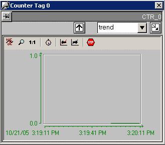
27 _CTR Standard View The standard view for the 505_CTR faceplate displays information on Value and Preset. Description Type Tag Description Static Text.#comment Value Customized Object.Value Value Units Static Text.Value#unit Preset Customized Object.Value_EUMax Preset Units Static Text.Value#unit Value Bar Graph Customized Object.Value File Trend View The trend view for the 505_CTR faceplate displays information in graph form on Value. The trend view is the standard view for displaying trends for the function block. For the 505_CTR function block the trend view displays the Value tag (Value). Only one trend window is needed for each function block type. A script assigns proper tags to the trend control at runtime. The trend control itself is actually the standard PCS 7 OS Trend Control. See the PCS 7 OS User Documentation for details on its operation. A5E

28 File Loop Display 3-12 A5E

29 _DI Standard View The standard view for the 505_DI faceplate displays information on Input Value and alarm settings. Description Type Tag Description Static Text.#comment DI Static Text.EventRaw#1 Alarm Enable Customized Object.DisableRaw File Alarm View The alarm view for the 505_DI faceplate displays alarm messages. The alarm view uses a standard WinCC Active X control. No modifications were made to it for the PCS 7 OS option. A5E

30 File Loop Display 3-14 A5E

31 _DI10 Standard View The standard view for the 505_DI10 faceplate displays information on Inputs and alarm settings. Description Type Tag Description Static Text.#comment DI1 Static Text.EventRaw#1 DI2 Static Text.EventRaw#1 DI3 Static Text.EventRaw#1 DI4 Static Text.EventRaw#1 DI5 Static Text.EventRaw#1 DI6 Static Text.EventRaw#1 DI7 Static Text.EventRaw#1 DI8 Static Text.EventRaw#1 DI9 Static Text.EventRaw#1 DI10 Static Text.EventRaw#1 Alarm Enable1 Customized Object.DisableRaw Alarm Enable2 Customized Object.DisableRaw Alarm Enable3 Customized Object.DisableRaw Alarm Enable4 Customized Object.DisableRaw Alarm Enable5 Customized Object.DisableRaw Alarm Enable6 Customized Object.DisableRaw Alarm Enable7 Customized Object.DisableRaw Alarm Enable8 Customized Object.DisableRaw Alarm Enable9 Customized Object.DisableRaw Alarm Enable10 Customized Object.DisableRaw A5E

32 File Alarm View The alarm view for the 505_DI10 faceplate displays alarm messages. The alarm view uses a standard WinCC Active X control. No modifications were made to it for the PCS 7 OS option. File Loop Display 3-16 A5E
 Static Text.EventRaw#1 DO (command) Customized Object.DO Alarm Enable Customized Object.DisableRaw File Name: @PG_505_DO_STANDARD.")
33 _DO Standard View The standard view for the 505_DO faceplate displays information on Output Value and alarm settings. Description Type Tag Description Static Text.#comment DO (status) Static Text.EventRaw#1 DO (command) Customized Object.DO Alarm Enable Customized Object.DisableRaw File Alarm View The alarm view for the 505_DO faceplate displays alarm messages. The alarm view uses a standard WinCC Active X control. No modifications were made to it for the PCS 7 OS option. A5E

34 File Loop Display 3-18 A5E
 Static Text.EventRaw#1 DO2 (status) Static Text.EventRaw#1 DO3 (status) Static Text.EventRaw#1 DO4 (status) Static Text.EventRaw#1 DO5 (status) Static Text.")
35 _DO10 Standard View The standard view for the 505_DO10 faceplate displays information on Outputs and alarm settings. Description Type Tag Description Static Text.#comment DO1 (status) Static Text.EventRaw#1 DO2 (status) Static Text.EventRaw#1 DO3 (status) Static Text.EventRaw#1 DO4 (status) Static Text.EventRaw#1 DO5 (status) Static Text.EventRaw#1 DO6 (status) Static Text.EventRaw#1 DO7 (status) Static Text.EventRaw#1 DO8 (status) Static Text.EventRaw#1 DO9 (status) Static Text.EventRaw#1 DO10 (status) Static Text.EventRaw#1 DO1 (command) Customized Object.DO1 DO2 (command) Customized Object.DO2 DO3 (command) Customized Object.DO3 DO4 (command) Customized Object.DO4 DO5 (command) Customized Object.DO5 DO6 (command) Customized Object.DO6 DO7 (command) Customized Object.DO7 DO8 (command) Customized Object.DO8 DO9 (command) Customized Object.DO9 A5E
36 DO10 (command) Customized Object.DO10 Alarm Enable1 Customized Object.DisableRaw Alarm Enable2 Customized Object.DisableRaw Alarm Enable3 Customized Object.DisableRaw Alarm Enable4 Customized Object.DisableRaw Alarm Enable5 Customized Object.DisableRaw Alarm Enable6 Customized Object.DisableRaw Alarm Enable7 Customized Object.DisableRaw Alarm Enable8 Customized Object.DisableRaw Alarm Enable9 Customized Object.DisableRaw Alarm Enable10 Customized Object.DisableRaw File Alarm View The alarm view for the 505_DO10 faceplate displays alarm messages. The alarm view uses a standard WinCC Active X control. No modifications were made to it for the PCS 7 OS option. File 3-20 A5E

37 Loop Display A5E

38 _IVAR Standard View The standard view for the 505_IVAR faceplate displays information on Value. Description Type Tag Description Static Text.#comment Value Customized Object.Value Value Units Static Text.Value#unit Value Bar Graph Customized Object.Value File 3-22 A5E
. Only one trend window is needed for each function block type.")
39 Trend View The trend view for the 505_IVAR faceplate displays information in graph form on Value. The trend view is the standard view for displaying trends for the function block. For the 505_IVAR function block the trend view displays the Value tag (Value). Only one trend window is needed for each function block type. A script assigns proper tags to the trend control at runtime. The trend control itself is actually the standard PCS 7 OS Trend Control. See the PCS 7 OS User Documentation for details on its operation. File Loop Display A5E

40 _LOOP Standard View The standard view for the 505_LOOP faceplate displays information on PV, SP, Out, Mode, and alarm limits. Description Type Tag Description Static Text.#comment PV Value Customized Object.PV PV Units Static Text.PV#unit SP Value Customized Object.SP SP Units Static Text.PV#unit Out Value Customized Object.Out Out Units Static Text.Out#unit Mode Customized Object.Mode Out Bar Graph Customized Object.Out Alarm Bar Graphs Customized Object.HD_Lim,.LD_Lim,.HH_Lim,.H_Lim,.L_Lim,.LL_Lim, PV SP Bar Graphs Customized Object.PV,.SP File 3-24 A5E

41 Limits View The limits view for the 505_LOOP faceplate displays information on alarm limits. Description Type Tag High High Alarm Enable Customized Object.DisableRaw High High Alarm Limit Customized Object.HH_Lim High High Alarm Units Static Text.PV#unit High Alarm Enable Customized Object.DisableRaw High Alarm Limit Customized Object.H_Lim High Alarm Units Static Text.PV#unit Low Alarm Enable Customized Object.DisableRaw Low Alarm Limit Customized Object.L_Lim Low Alarm Units Static Text.PV#unit Low Low Alarm Enable Customized Object.DisableRaw Low Low Alarm Limit Customized Object.LL_Lim Low Low Alarm Units Static Text.PV#unit High Deviation Alarm Enable Customized Object.DisableRaw High Deviation Alarm Limit Customized Object.HD_Lim High Deviation Alarm Units Static Text.PV#unit Low Deviation Alarm Enable Customized Object.DisableRaw Low Deviation Alarm Limit Customized Object.LD_Lim Low Deviation Alarm Units Static Text.PV#unit Rate Of Change Alarm Enable Customized Object.DisableRaw Rate Of Change Alarm Limit Customized Object.ROC_Lim Rate Of Change Alarm Units Static Text.PV#unit Bad Transmitter Alarm Customized Object.DisableRaw File A5E
42 Alarm View The alarm view for the 505_LOOP faceplate displays alarm messages. The alarm view uses a standard WinCC Active X control. No modifications were made to it for the PCS 7 OS option. File 3-26 A5E

43 Tuning View The tuning view for the 505_LOOP faceplate displays information on tuning parameters. Description Type Tag Gain Customized Object.Gain Gain Units Static Text.Gain#unit Rate Customized Object.Rate Rate Units Static Text.Rate#unit Reset Customized Object.Reset Reset Units Static Text.Reset#unit File TUNING.PDL A5E


44 Trend View The trend view for the 505_LOOP faceplate displays information in graph form on PV, SP, and Out. The trend view is the standard view for displaying trends for the function block. For the 505_LOOP function block the trend view displays the process value (PV), setpoint (SP), and output value (Out). Only one trend window is needed for each function block type. A script assigns proper tags to the trend control at runtime. The trend control itself is actually the standard PCS 7 OS Trend Control. See the PCS 7 OS User documentation for details on its operation. File Loop Display (Small Trend) 3-28 A5E
 A5E00767202-01")
45 Loop Display (Large Trend) A5E

46 _MTR1 Standard View The standard view for the 505_MTR1 faceplate displays information on Mode, Setpoint, Status, Override, and alarm settings. Description Type Tag Description Static Text.#comment Mode Customized Object.Mode Setpoint Customized Object.Setpoint State Customized Object.EventRaw#1 Override Customized Object.Override Start Timeout Customized Object.Timeout1 Stop Timeout Customized Object.Timeout2 Not Running Alarm Enable Customized Object.DisableRaw Not Stopped Alarm Enable Customized Object.DisableRaw File 3-30 A5E

47 Alarm View The alarm view for the 505_MTR1 faceplate displays alarm messages. The alarm view uses a standard WinCC Active X control. No modifications were made to it for the PCS 7 OS option. File Loop Display A5E

48 _MTR2 The 505_MTR2 faceplate is identical to the 505_MTR1 faceplate in all respects except filenames, and the fact that the Setpoint value has 3 possible states instead of just 2, the Override value has 4 possible states instead of just 2, and there are 3 alarms to disable instead of just _RMTR The 505_RMTR faceplate is identical to the 505_MTR1 faceplate in all respects except filenames, and the fact that the Setpoint value has 3 possible states instead of just 2, the Override value has 4 possible states instead of just 2, and there are 3 alarms to disable instead of just A5E

49 _PLC Standard View The standard view for the 505_PLC faceplate displays information on State, Scan, MainConnStat, AltConnStat, and alarm settings. Description Type Tag Description Static Text.#comment State Static Text.State Scan Static Text.Scan Main Connection Status Static Text.MainConn Alt Connection Status Static Text.AltConn Connection Lost Alarm Enable Customized Object.DisableRaw RBE Full Alarm Enable Customized Object.DisableRaw Program Mode Alarm Enable Customized Object.DisableRaw File A5E

50 Status text will be colorized according to the following table: Tag Value Color State Unknown Magenta Run Green Program Yellow Fault Red Scan Off Red On Green MainConn Unavailable Yellow Available Green Scan On Green Fail Red AltConn Unavailable Yellow Available Green Scan On Green Fail Red Alarm View The alarm view for the 505_PLC faceplate displays alarm messages. File 3-34 A5E

51 Loop Display A5E

52 _TEXT Standard View The standard view for the 505_TEXT faceplate displays information on the three text values. Description Type Tag Description Static Text.#comment Text1 Customized Object.Text1 Text2 Customized Object.Text2 Text3 Customized Object.Text3 File 3-36 A5E

53 _TMR Standard View The standard view for the 505_TMR faceplate displays information on Value and Preset. Description Type Tag Description Static Text.#comment Value Customized Object.Value Value Units Static Text.Value#unit Preset Customized Object.Preset Preset Units Static Text.Value#unit Value, Preset Bar Graph Customized Object.Value,.Preset File A5E


54 Trend View The trend view for the 505_TMR faceplate displays information in graph form on Value. The trend view is the standard view for displaying trends for the function block. For the 505_TMR function block the trend view displays the Value tag (Value). Only one trend window is needed for each function block type. A script assigns proper tags to the trend control at runtime. The trend control itself is actually the standard PCS 7 OS Trend Control. See the PCS 7 OS User Documentation for details on its operation. File Loop Display 3-38 A5E

55 _VLV1 Standard View The standard view for the 505_VLV1 faceplate displays information on Mode, Setpoint, Status, Override, and alarm settings. Description Type Tag Description Static Text.#comment Mode Customized Object.Mode Setpoint Customized Object.Setpoint State Customized Object.EventRaw#1 Override Customized Object.Override Open Timeout Customized Object.Timeout1 Close Timeout Customized Object.Timeout2 Not Closed Alarm Enable Customized Object.DisableRaw Not Opened Alarm Enable Customized Object.DisableRaw File A5E

56 Alarm View The alarm view for the 505_VLV1 faceplate displays alarm messages. The alarm view uses a standard WinCC Active X control. No modifications were made to it for the PCS 7 OS option. File Loop Display 3-40 A5E

57 _VLV2 The 505_VLV2 faceplate is identical to the 505_VLV1 faceplate in all respects except filenames, and the fact that the Override value has 4 possible states instead of just 2, and there are 3 alarms to disable instead of just 2. A5E
58

59 4 Action Requests 4.1 Overview of Action Requests An Action Request consists of a configuration mechanism to annunciate an event, and a procedure that you must perform to clear the event. The ACTION_REQUEST faceplate displays basic information about the Action Request. This information varies based on the AnswerFormat that was configured for the Action Request. There are six types of AnswerFormat: Acknowledge: The user enters a comment and presses the Commit button. View: The Action Request is automatically acknowledged simply by displaying the faceplate. No further user action is required. Event Log: A message is automatically entered into the alarm logging system when the Action Request is triggered. No further annunciation is made to the user, and no user action is required from the faceplate. Enter Value: The user enters a value to be written to the AnswerTag, enters a comment, and presses the Commit button. Multiple Choice: The user selects a value to be written to the AnswerTag from the pre-configured list, enters a comment, and presses the Commit button. Multiple Choice (OSx Style): The user selects a value to be written to the AnswerTag from the pre-configured list, enters a comment, and presses the Commit button. The text displayed in the list is for informational purposes only. A5E
60 Action Requests Fixed values are always written to the AnswerTag according to the following table: - Choice 1: 0x Choice 2: 0x Choice 3: 0x Choice 4: 0x8000 Note The 505 PLC must be configured such that a write to the Action Request s reset tag will clear the trigger tag. In a system architecture that has redundant PCS 7 OS Servers, the Action Request status will not be cleared on the redundant server until the trigger tag is cleared. If there is a delay between the writing of the reset tag and a clearing of the trigger tag, the Action Request status on the redundant PCS 7 OS Server will not agree during this delay period. 4-2 A5E

61 Action Requests 4.2 ACTION_REQUEST Standard View The standard view for the ACTION_REQUEST faceplate displays information on current value, new value, and answer format. Key Type Description Tag 1 Static Text Time.TimeStamp 2 Static Text Description.Message 3 Static Text Comment.Comment 4 Customized Object Answer Tag Current Value.AnswerTag (Shown only for "EnterValue" and "Multi-choice" AnswerFormats) 5 Customized Object Answer Tag New Value.AnswerTag (Shown only for "EnterValue"AnswerFormat. "Multi-choice" AnswerFormat displays 4 radio buttons) 6 Static Text Answer Format.AnswerFormat 7 Button Commit Button N/A 8 Button Cancel Button N/A The radio buttons are only displayed in the Multiple Choice case. The Enter Value I/O field is only displayed in the Enter Value case. To confirm the Action Request, you enter a comment and select (or enter) a value to be written to the AnswerTag, if configured. A5E
62 Action Requests When you click the Commit button, the following actions take place: - The chosen value is written to the AnswerTag. - The configured ResetTag is reset. - The Action Request is acknowledged (ACKed), clearing the alarm annunciators. - A record of the action is written to the Operator Log. File ACTION_REQUEST_STANDARD.PDL 4-4 A5E
SIMATIC. PCS 7/505 OS Setup Guide for V6.1. Preface, Contents. Introduction 1. Install the Software. Update a project from V6.0 to V6.
 s SIMATIC PCS 7/505 OS Setup Guide for V6.1 Manual Preface, Contents Introduction 1 Install the Software 2 Update a project from V6.0 to V6.1 3 Create a New OS Project 4 Deploy the Changes 5 Modify Faceplates
SIMATIC Automation License Manager Manual 02/2008 A5E
 s Contents SIMATIC Automation License Manager Product Overview 1 Installation 2 Working with the Automation License Manager 3 Glossar Index Manual 02/2008 A5E02128430-01 Safety Guidelines This manual contains
Readme SiVArc V14 SP1 Update 6
 Product version 1 Improvements in Update 6 2 Readme 05/2018 Legal information Warning notice system This manual contains notices you have to observe in order to ensure your personal safety, as well as
Deckblatt. APL Operator Guide SIMATIC PCS 7. Application description June Applikationen & Tools. Answers for industry.
 Deckblatt SIMATIC PCS 7 Application description June 2011 Applikationen & Tools Answers for industry. Industry Automation and Drive Technologies Service & Support Portal This article is taken from the
First Steps with S7-PDIAG and ProAgent
 s SIMATIC S7-PDIAG for S7-300 and S7-400 Configuring Process Diagnostics Getting Started Edition 07/2005 First Steps with S7-PDIAG and ProAgent The Getting Started for This product is not a stand-alonedescription.
Operator Station (V8.0) SIMATIC. Process Control System PCS 7 Operator Station (V8.0) Preface 1. The PCS 7 Operator Station
 SIMATIC. Process Control System PCS 7 Operator Station (V8.0) Preface 1. The PCS 7 Operator Station") SIMATIC Process Control System PCS 7 Configuration Manual Preface 1 The PCS 7 Operator Station 2 Introduction to OS configuration 3 Setting languages 4 Configuring OS data in SIMATIC Manager 5 Configuring
SIMATIC Process Control System PCS 7 Configuration Manual Preface 1 The PCS 7 Operator Station 2 Introduction to OS configuration 3 Setting languages 4 Configuring OS data in SIMATIC Manager 5 Configuring
Creating the program. TIA Portal. SIMATIC Creating the program. Loading the block library 1. Deleting program block Main [OB1]
![Creating the program. TIA Portal. SIMATIC Creating the program. Loading the block library 1. Deleting program block Main [OB1]](/thumbs/72/66854455.jpg "Creating the program. TIA Portal. SIMATIC Creating the program. Loading the block library 1. Deleting program block Main [OB1]") Loading the block library 1 Deleting program block Main [OB1] 2 TIA Portal SIMATIC Getting Started Copying program blocks 3 Copying tag tables 4 Compiling a project 5 Load project into the CPU 6 03/2013
Loading the block library 1 Deleting program block Main [OB1] 2 TIA Portal SIMATIC Getting Started Copying program blocks 3 Copying tag tables 4 Compiling a project 5 Load project into the CPU 6 03/2013
Team engineering via Inter Project. Engineering. TIA Portal. Team engineering via Inter Project Engineering. Basics of "Inter Project Engineering"
 Team engineering via Inter Project Engineering TIA Portal Basics of "Inter Project Engineering" 1 Creating an IPE file 2 Importing an IPE file 3 Team engineering via Inter Project Engineering Getting Started
SIMATIC. Communications processor CP First Steps in Commissioning. Getting Started 09/2008 A5E
 SIMATIC Communications processor Getting Started 09/2008 A5E02291899-01 Legal information Warning notice system This manual contains notices you have to observe in order to ensure your personal safety,
SIMATIC HMI. Software RemoteOperate V2. Preface. Overview 1. Range of functions of the RemoteOperate software. Hardware and software requirements
 Preface SIMATIC HMI Software SIMATIC HMI Software Programming Manual Overview 1 Range of functions of the RemoteOperate software 2 Hardware and software requirements 3 Installing RemoteOperate 4 Server
SIMATIC. Process Control PCS 7 V7.0 PCS 7 OS Process Control. Preface, Contents. Additional Documentation 1 Functions of the PCS 7 OS in Process Mode
 s SIMATIC Process Control PCS 7 V7.0 PCS 7 OS Process Control Operating Instructions Preface, Contents Additional Documentation 1 Functions of the PCS 7 OS in Process Mode 2 PCS 7 OS Process Mode - User
DANGER indicates that death or severe personal injury will result if proper precautions are not taken.
 Preface Overview 1 SIMATIC Process Control System PCS 7 Advanced Process Functions Operator Manual Operating Manual Material management 2 Material lot management 3 Storage location management 4 Parameter
SIMATIC. ET 200S distributed I/O Digital electronic module 4DO DC24V/0.5A ST (6ES7132-4BD02-0AA0) Preface. Properties 2. Diagnostics 3.
 Preface. Properties 2. Diagnostics 3.") Preface 1 Properties 2 SIMATIC Diagnostics 3 ET 200S distributed I/O Digital electronic module 4DO DC24V/0.5A ST (6ES7132-4BD02- Manual 01/2008 A5E01254028-01 Safety Guidelines This manual contains notices
Preface 1 Properties 2 SIMATIC Diagnostics 3 ET 200S distributed I/O Digital electronic module 4DO DC24V/0.5A ST (6ES7132-4BD02- Manual 01/2008 A5E01254028-01 Safety Guidelines This manual contains notices
SIMATIC. Function modules FM 351 First Steps in Commissioning. Purpose of the Getting Started. Requirements 2
 Purpose of the Getting Started 1 Requirements 2 SIMATIC Function modules FM 351 First Steps in Commissioning Getting Started Installing the configuration package on the PG 3 FM 351, installing and wiring
SIMATIC. Process Control System PCS 7 Licenses and quantity structures (V8.0) Preface 1. Selecting the correct license keys 2
 Preface 1. Selecting the correct license keys 2") Preface 1 Selecting the correct license keys 2 SIMATIC Process Control System PCS 7 Licenses and quantity structures (V8.0) Licensing of PC stations 3 Data volumes 4 Installation Manual 05/2012 A5E03805083-02
Preface 1 Selecting the correct license keys 2 SIMATIC Process Control System PCS 7 Licenses and quantity structures (V8.0) Licensing of PC stations 3 Data volumes 4 Installation Manual 05/2012 A5E03805083-02
SIMATIC. ET 200S distributed I/O Digital electronic module 4DO DC24V/0.5 A ST (6ES7132-4BD01-0AA0) Preface. Properties 1. Diagnostics 2.
 Preface. Properties 1. Diagnostics 2.") SIMATIC ET 200S distributed I/O Digital electronic module 4DO DC24V/0.5 A ST (6ES7132-4BD01- SIMATIC Preface Properties 1 Diagnostics 2 ET 200S distributed I/O Digital electronic module 4DO DC24V/0.5 A
SIMATIC ET 200S distributed I/O Digital electronic module 4DO DC24V/0.5 A ST (6ES7132-4BD01- SIMATIC Preface Properties 1 Diagnostics 2 ET 200S distributed I/O Digital electronic module 4DO DC24V/0.5 A
ET 200S distributed I/O Digital electronic module 2DO AC V (6ES7132-4FB01-0AB0)
") SIMATIC ET 200S distributed I/O SIMATIC Preface ET 200S distributed I/O Digital electronic module 2DO AC24..230V (6ES7132-4FB01-0AB0) Properties 1 Parameters 2 Diagnostics 3 Manual 04/2007 A5E01077264-01
SIMATIC ET 200S distributed I/O SIMATIC Preface ET 200S distributed I/O Digital electronic module 2DO AC24..230V (6ES7132-4FB01-0AB0) Properties 1 Parameters 2 Diagnostics 3 Manual 04/2007 A5E01077264-01
SIMATIC HMI. WinCC V7.4 WinCC/Options for Process Control. Overview of process control system options 1. OS Project Editor 2.
 Overview of process control system options 1 OS Project Editor 2 SIMATIC HMI WinCC V7.4 System Manual Horn 3 Time Synchronization 4 Lifebeat Monitoring 5 Picture Tree Manager 6 Graphic Object Update Wizard
Siemens Industrial Spares
 s SIMATIC PCS 7/APACS+ OS DBA Users Guide for V6.1 Manual Preface, Contents Quick Start 1 Project Setup 2 AS View 3 Plant View 4 PC Station View 5 Compiling the Project 6 Object Attributes 7 Advanced Topics
SIMATIC. Process Control System PCS 7 Product Brief on Software Updates from V5.1/V5.2 to PCS 7 V7.0 SP1. Preface 1
 SIMATIC Process Control System PCS 7 SIMATIC Process Control System PCS 7 Product Brief on Software Updates from V5.1/V5.2 to PCS 7 V7.0 SP1 Commissioning Manual Preface 1 Before beginning the software
SIMOTION. SIMOTION SCOUT Task Trace. Preface 1. Overview 2. Configuring 3. Working with the SIMOTION Task Profiler. Function Manual 05/2009
 SIMOTION SIMOTION SCOUT SIMOTION SIMOTION SCOUT Preface 1 Overview 2 Configuring 3 Working with the SIMOTION Task Profiler 4 Function Manual 05/2009 Legal information Legal information Warning notice system
SIMATIC. Process control system PCS 7 Operator Station (V9.0 SP1) Security information 1. Preface 2
 Security information 1. Preface 2") SIMATIC Process control system PCS 7 Configuration Manual Valid for PCS 7 as of V9.0 SP1 Security information 1 Preface 2 The PCS 7 Operator Station 3 Introduction to OS configuration 4 Setting the languages
SIMATIC Process control system PCS 7 Configuration Manual Valid for PCS 7 as of V9.0 SP1 Security information 1 Preface 2 The PCS 7 Operator Station 3 Introduction to OS configuration 4 Setting the languages
PROFIsafe SITRANS. Pressure transmitter SITRANS P, DS III PROFIsafe series. Product Information 7MF4*34 04/2008 A5E
 1 SITRANS Pressure transmitter SITRANS P, DS III PROFIsafe series Product Information 7MF4*34 04/2008 A5E00732533-02 Safety Guidelines This manual contains notices you have to observe in order to ensure
SIMATIC. Process Control System PCS 7 OS Process Control (V8.1) Preface 1. Additional documentation 2. Functions of the PCS 7 OS in process mode 3
 Preface 1. Additional documentation 2. Functions of the PCS 7 OS in process mode 3") Preface 1 Additional documentation 2 SIMATIC Process Control System PCS 7 Operating Instructions Functions of the PCS 7 OS in process mode 3 PCS 7 OS process mode - user interface 4 System operator inputs
Preface 1 Additional documentation 2 SIMATIC Process Control System PCS 7 Operating Instructions Functions of the PCS 7 OS in process mode 3 PCS 7 OS process mode - user interface 4 System operator inputs
Preface 1. Master Data System 2. Contact Information 3. User Manual Master Data System. English. Release English
 Preface 1 Master Data System 2 Contact Information 3 X-Tools User Manual - 02 - Master Data System Release 2014-11 Release 2014-11 1 / 21 Safety Guidelines This document contains notices which you should
SIMATIC HMI. WinCC V7.0 SP1 Setting up a Message System. WinCC Alarm Logging 1. Message System in WinCC 2. Principles of the Message System
 SIMATIC HMI WinCC V7.0 SP1 SIMATIC HMI WinCC V7.0 SP1 WinCC Alarm Logging 1 Message System in WinCC 2 Principles of the Message System 3 Configuring the Message System 4 Printout of the Online Help 11/2008
SIMATIC. Component Based Automation SIMATIC imap STEP 7 AddOn Creating PROFINET components. Preface. Creating PROFINET components in STEP 7
 SIMATIC Component Based Automation SIMATIC Component Based Automation SIMATIC imap STEP 7 AddOn Creating PROFINET components Configuration Manual Preface Creating PROFINET components in STEP 7 1 SIMATIC
SIMATIC HMI. WinCC V7.4 SP1 SIMATIC HMI WinCC V7.4 Getting Started. Welcome 1. Icons 2. Creating a project. Configure communication
 Welcome 1 Icons 2 SIMATIC HMI WinCC V7.4 SP1 SIMATIC HMI WinCC V7.4 Getting Started Getting Started Creating a project 3 Configure communication 4 Configuring the Process Screens 5 Archiving and displaying
SIMATIC IPC Wizard for. Widescreen devices with multitouch SIMATIC. Industrial PC SIMATIC IPC Wizard for. Preface.
 SIMATIC IPC Wizard 2.0.1 for Widescreen devices with multi-touch SIMATIC Industrial PC SIMATIC IPC Wizard 2.0.1 for Widescreen devices with multitouch Operating Manual Preface Overview 1 Installing IPC
DANGER indicates that death or severe personal injury will result if proper precautions are not taken.
 SIMATIC ET 200S distributed I/O SIMATIC ET 200S distributed I/O Digital electronic module 4DI DC24V HF (6ES7131-4BD01-0AB0) Manual Preface Properties 1 Parameters 2 Diagnostics 3 04/2007 A5E01077141-01
SIMATIC. Communications processor CP 340 first commissioning steps. Getting Started 04/2005 A5E
 SIMATIC Communications processor Getting Started 04/2005 A5E00442606-01 Safety Guidelines This manual contains notices you have to observe in order to ensure your personal safety, as well as to prevent
HawkEye 45T Display User Manual
 HawkEye 45T Display User Manual Rev 1.0.1, December 2006 EM-20889-1V101 Safety Guidelines This manual contains notices you have to observe in order to ensure your personal safety, as well as to prevent
SIMATIC. Process Control System PCS 7 First Steps (V7.1) Preface 1. Creating the PCS 7 Project 2. Configuring the hardware and networks
 Preface 1. Creating the PCS 7 Project 2. Configuring the hardware and networks") SIMATIC Process Control System PCS SIMATIC Process Control System PCS 7 Getting Started Preface 1 Creating the PCS 7 Project 2 Configuring the hardware and networks 3 Configuring the process tags and the
SIMATIC Process Control System PCS SIMATIC Process Control System PCS 7 Getting Started Preface 1 Creating the PCS 7 Project 2 Configuring the hardware and networks 3 Configuring the process tags and the
Key Panels Library SIMATIC HMI. Key Panels Library. Preface 1. Installation of Key Panels Library. Working with the Key Panels Library
 Preface 1 Installation of Key Panels Library 2 SIMATIC HMI Working with the Key Panels Library 3 Function description 4 Configuration Manual 11/2011 A5E03740571-01 Legal information Legal information Warning
SIMATIC. Process Control System PCS 7 OS Process Control (V8.1) Security information 1. Preface 2. Additional documentation 3
 Security information 1. Preface 2. Additional documentation 3") Security information 1 Preface 2 SIMATIC Process Control System PCS 7 Operating Instructions Additional documentation 3 Functions of the PCS 7 OS in process mode 4 PCS 7 OS process mode - user interface
Security information 1 Preface 2 SIMATIC Process Control System PCS 7 Operating Instructions Additional documentation 3 Functions of the PCS 7 OS in process mode 4 PCS 7 OS process mode - user interface
SIMATIC. Process Control System PCS 7 PCS 7 system documentation - Readme V8.0 SP2 (Update 1) Options for Accessing Documentation 1
 Options for Accessing Documentation 1") Options for Accessing Documentation 1 Notes on the Product Documentation 2 SIMATIC Notes on the PCS 7 V8.0 SP2 system documentation 3 Process Control System PCS 7 PCS 7 system documentation - Readme V8.0
Options for Accessing Documentation 1 Notes on the Product Documentation 2 SIMATIC Notes on the PCS 7 V8.0 SP2 system documentation 3 Process Control System PCS 7 PCS 7 system documentation - Readme V8.0
SIMATIC HMI. WinCC V7.0 SP1 MDM - WinCC/Options for Process Control. Overview of process control system options 1. OS Project Editor 2.
 Overview of process control system options 1 OS Project Editor 2 SIMATIC HMI WinCC V7.0 SP1 MDM - WinCC/Options for Process Control System Manual Horn 3 Time Synchronization 4 Lifebeat Monitoring 5 Picture
SIMATIC. ET 200S distributed I/O Power module PM-E DC24..48V (6ES7138-4CA50-0AB0) Preface. Properties 1. Parameters 2. Diagnostics 3.
 Preface. Properties 1. Parameters 2. Diagnostics 3.") SIMATIC ET 200S distributed I/O SIMATIC ET 200S distributed I/O Power module PM-E DC24..48V (6ES7138-4CA50-0AB0) Preface Properties 1 Parameters 2 Diagnostics 3 Configuring 4 Manual 04/2007 A5E01119980-01
SIMATIC ET 200S distributed I/O SIMATIC ET 200S distributed I/O Power module PM-E DC24..48V (6ES7138-4CA50-0AB0) Preface Properties 1 Parameters 2 Diagnostics 3 Configuring 4 Manual 04/2007 A5E01119980-01
S7-300 Getting Started - Commissioning a CPU 31xC: Closed-loop control
 Getting Started - Commissioning a CPU Introduction 1 31xC: Closed-loop control Preparation 2 SIMATIC S7-300 Getting Started - Commissioning a CPU 31xC: Closed-loop control Learning units 3 Further Information
SIMATIC. Process Control System PCS 7 Advanced Process Functions Operator Manual. Preface. Security information 1. Overview 2. Material management 3
 Preface Security information 1 SIMATIC Process Control System PCS 7 Advanced Process Functions Operator Manual Operating Manual Overview 2 Material management 3 Material lot management 4 Storage location
SIMATIC. Process Control System PCS 7 Trend Micro OfficeScan (V8.0; V8.0 SP1) Configuration. Using virus scanners 1.
 Configuration. Using virus scanners 1.") SIMATIC Process Control System PCS 7 Using virus scanners 1 Configuration 2 SIMATIC Process Control System PCS 7 Trend Micro OfficeScan (V8.0; V8.0 SP1) Configuration Commissioning Manual 08/2009 A5E02634982-01
SIMATIC Process Control System PCS 7 Using virus scanners 1 Configuration 2 SIMATIC Process Control System PCS 7 Trend Micro OfficeScan (V8.0; V8.0 SP1) Configuration Commissioning Manual 08/2009 A5E02634982-01
RF-MANAGER simulator SIMATIC. RFID-Systems RF-MANAGER simulator. Simulating projects. Compact Operating Instructions 06/2010 A5E
 Simulating projects 1 SIMATIC RFID-Systems Compact Operating Instructions 06/2010 A5E01074276-03 Legal information Legal information Warning notice system This manual contains notices you have to observe
Preface 1. X-Tools Client 2. Contact Information 3. User Manual X-Tools Client. English. Release English. Release / 25
 Preface 1 X-Tools Client 2 Contact Information 3 X-Tools User Manual - 02 - X-Tools Client Release 2015-11 Release 2015-11 1 / 25 Safety Guidelines This document contains notices which you should observe
SIMATIC. WinCC Readme Runtime Professional. Validity 1. Improvements in Update 2 2. Improvements in Update 1 3
 Validity 1 Improvements in Update 2 2 SIMATIC WinCC Improvements in Update 1 3 Performance features of Runtime Professional 4 Readme 03/2017 Legal information Warning notice system This manual contains
SIMATIC. WinCC Readme Runtime Professional. Validity 1. Improvements in Update 7 2. Improvements in Update 6 3. Improvements in Update 5 4
 Validity 1 Improvements in Update 7 2 SIMATIC WinCC Readme Improvements in Update 6 3 Improvements in Update 5 4 Improvements in Update 3 5 Improvements in Update 2 6 Improvements in Update 1 7 Performance
Block Library Motor Starter SIRIUS for SIMATIC PCS 7
 Industrial Controls Block Library Motor Starter SIRIUS for SIMATIC PCS 7 SIRIUS Motor Starter PCS 7 Library V7.1+SP2 / SIRIUS Motor Starter PCS 7 Library V8 Migration 8.0+SP1 Getting Started Edition 08/2013
Web Option for OS (V8.0) SIMATIC. Process Control System PCS 7 Web Option for OS (V8.0) Preface 1. Additional documentation
 SIMATIC. Process Control System PCS 7 Web Option for OS (V8.0) Preface 1. Additional documentation") Preface 1 Additional documentation 2 SIMATIC Process Control System PCS 7 Function Manual Overview of the Web Option for OS 3 Configuration with Web Option for OS 4 Hardware and Software Requirements 5
Preface 1 Additional documentation 2 SIMATIC Process Control System PCS 7 Function Manual Overview of the Web Option for OS 3 Configuration with Web Option for OS 4 Hardware and Software Requirements 5
English. SIMATIC Sensors. RFID-Systems RF600. Getting Started. Edition 11/2005; J31069-D0172-U001-A1-7618
 English SIMATIC Sensors RFID-Systems Getting Started Edition 11/2005; J31069-D0172-U001-A1-7618 Safety Guidelines This manual contains notices you have to observe in order to ensure your personal safety,
SIMATIC. Process Control System PCS 7 V7.0 SP1 Software Update With Utilization of New Functions (PCS 7 V6.x to V7.0 SP1) Preface.
 Preface.") SIMATIC Process Control System PCS 7 V7.0 SP1 Software Update With Utilization of New Functions (PCS 7 V6.x to V7.0 SP1) SIMATIC Process Control System PCS 7 V7.0 SP1 Software Update With Utilization of
SIMATIC Process Control System PCS 7 V7.0 SP1 Software Update With Utilization of New Functions (PCS 7 V6.x to V7.0 SP1) SIMATIC Process Control System PCS 7 V7.0 SP1 Software Update With Utilization of
SIMATIC. S7/HMI SIMATIC Automation Tool V3.1 SP1 product information. SIMATIC Automation Tool features 1. Known problems. Product Information
 SIMATIC Automation Tool features 1 Known problems 2 SIMATIC S7/HMI SIMATIC Automation Tool V3.1 SP1 product information Product Information V3.1 SP1, 05/2018 A5E43714043-AA Legal information Warning notice
Class documentation. COMOSKDictionary COMOS. Platform Class documentation COMOSKDictionary. Trademarks. General. KDictionary. Programming Manual
 Class documentation COMOSKDictionary COMOS Trademarks 1 General 2 KDictionary 3 Platform Class documentation COMOSKDictionary Programming Manual 04/2012 A5E03777026-01 Legal information Legal information
SIMATIC. Process Control System PCS 7 Operator Station. Preface, Contents. The PCS 7 OS 1 Introduction to PCS 7 OS Configuration
 s SIMATIC Process Control System PCS 7 Operator Station Configuration Manual Preface, Contents The PCS 7 OS 1 Introduction to PCS 7 OS Configuration 2 Configuring the PCS 7 OS Data in the SIMATIC Manager
SIMATIC. Process Control System PCS 7 Configuration McAfee Endpoint Security Security information 1. Preface 2.
 Security information 1 Preface 2 SIMATIC Configuration 3 Process Control System PCS 7 Configuration McAfee Endpoint Security 10.5 Installation Manual 03/2018 A5E44395618-AA Legal information Warning notice
SIMATIC. PCS 7/APACS+ OS Symbols and Faceplates Users Guide for V6.1. Preface, Contents. Common HMI Elements SINGLE_LOOP_AFB. Other Faceplates.
 s SIMATIC PCS 7/APACS+ OS Symbols and Faceplates Users Guide for V6.1 Manual Preface, Contents Common HMI Elements 1 SINGLE_LOOP_AFB 2 Other Faceplates 3 Edition 11/2005 A5E00595267-01 Safety Guidelines
SFC Visualization (V8.0 SP1) SIMATIC. Process Control System PCS 7 SFC Visualization (V8.0 SP1) What's new in SFV? 1. SFC Visualization (SFV)
 SIMATIC. Process Control System PCS 7 SFC Visualization (V8.0 SP1) What's new in SFV? 1. SFC Visualization (SFV)") What's new in SFV? 1 SFC Visualization (SFV) 2 SIMATIC Process Control System PCS 7 Programming and Operating Manual Basic SFC settings 3 Configuration 4 Operating and monitoring SFCs 5 Appendix 6 12/2012
What's new in SFV? 1 SFC Visualization (SFV) 2 SIMATIC Process Control System PCS 7 Programming and Operating Manual Basic SFC settings 3 Configuration 4 Operating and monitoring SFCs 5 Appendix 6 12/2012
SIMATIC. Process Control System PCS 7 VT Readme V8.2 (online) Security information 1. Overview 2. Notes on Installation 3. Notes on usage 4.
 Security information 1. Overview 2. Notes on Installation 3. Notes on usage 4.") Security information 1 Overview 2 SIMATIC Process Control System PCS 7 Notes on Installation 3 Notes on usage 4 Readme 04/2016 A5E36515375-AA Legal information Warning notice system This manual contains
Security information 1 Overview 2 SIMATIC Process Control System PCS 7 Notes on Installation 3 Notes on usage 4 Readme 04/2016 A5E36515375-AA Legal information Warning notice system This manual contains
Preface Master Data System Contact Information SIPLUS CMS
 Preface 1 Master Data System 2 Contact Information 3 X-Tools User Manual - 02 - Master Data System Release 2012-09 Release 2012-09 1 / 17 Safety Guidelines This document contains notices which you should
SIMATIC. Process Control System PCS 7 V7.0 SP1 Security Information Note: Setting up antivirus software. Preface. Using virus scanners 2
 SIMATIC Process Control System PCS 7 V7.0 SP1 SIMATIC Process Control System PCS 7 V7.0 SP1 Security Information Note: Setting up antivirus software Security Information Note Preface 1 Using virus scanners
SIMATIC. Process Control System PCS 7 OS Web Option (V7.1) Preface 1. Additional documentation 2. Overview of PCS 7 OS Web Option
 Preface 1. Additional documentation 2. Overview of PCS 7 OS Web Option") SIMATIC SIMATIC Process Control System PCS 7 Function Manual Preface 1 Additional documentation 2 Overview of PCS 7 OS Web Option 3 Configuration with PCS 7 OS Web option 4 Hardware and Software Requirements
SIMATIC SIMATIC Process Control System PCS 7 Function Manual Preface 1 Additional documentation 2 Overview of PCS 7 OS Web Option 3 Configuration with PCS 7 OS Web option 4 Hardware and Software Requirements
SIWAREX U PCS7. Advanced Process Library Version 12/2013
 SIWAREX U PCS7 Advanced Process Library Version 12/2013 Safety This manual contains notices you have to observe in order to ensure your personal safety, as well as to prevent damage to property. The notices
SIMATIC. RFID systems User application for RF610M Mobile Reader. Introduction. Description 2. Installing Software 3. Parameterization of the software
 SIMATIC RFID systems SIMATIC RFID systems User application for RF610M Mobile Reader Operating Instructions Introduction 1 Description 2 Installing Software 3 Parameterization of the software 4 Read and
General Information 1. Connection 2. User Interface 3 ATC5300. Menus 4. Automatic Transfer Controller. Remote Control Software Manual A5E
 s General Information 1 Connection 2 Automatic Transfer Controller User Interface 3 Menus 4 Remote Control Software Manual Edition 01/2010 A5E02469028-01 Legal information Warning notice system This manual
SIMATIC. Process Control System PCS 7 Software update with utilization of new functions. Security information 1. Preface 2.
 Security information 1 Preface 2 SIMATIC Process Control System PCS 7 Software update with utilization of new functions Service Manual Introduction 3 Overview of Upgrade Steps 4 Preparing for the software
PD PA AP How To Configure Maxum II TimeServer Access
 Designating the TimeServer on the Analyzer 1 Running a TimeServer as an Application 2 Allowing the TimeServer Application Through the Firewall 3 PD PA AP How To Configure Maxum II TimeServer Access Application
COMOS. Platform Class documentation RevisionMaster_dll. Class: RevisionInfo 1. Class: RevisionMaster 2. Programming Manual
 Class: RevisionInfo 1 Class: RevisionMaster 2 COMOS Platform Class documentation RevisionMaster_dll Programming Manual 03/2017 V10.2.1 A5E39859923-AA Legal information Warning notice system This manual
SIMATIC. Process Control System PCS 7 PCS 7 Documentation (V8.1) Options for Accessing Documentation 1. Documentation for the Planning Phase 2
 Options for Accessing Documentation 1. Documentation for the Planning Phase 2") Options for Accessing Documentation 1 Documentation for the Planning Phase 2 SIMATIC Process Control System PCS 7 Documentation for the Realization Phase 3 Documentation on commissioning, operation, diagnostics
Options for Accessing Documentation 1 Documentation for the Planning Phase 2 SIMATIC Process Control System PCS 7 Documentation for the Realization Phase 3 Documentation on commissioning, operation, diagnostics
Siemens Industrial SIMATIC. Process Control System PCS 7 Configuration Trend Micro OfficeScan Server XG. Security information 1.
 Security information 1 Preface 2 SIMATIC Configuration 3 Process Control System PCS 7 Configuration Trend Micro OfficeScan Server XG Commissioning Manual Siemens Industrial 03/2018 A5E44395601-AA Legal
Industrial Controls. SIMOCODE pro SIMOCODE pro PCS 7 Library. Preface. Security information. Product specific security. information.
 Industrial Controls SIMOCODE pro Preface 1 Product specific security Security information 2 information 3 Introduction 4 5 References 6 List of Abbreviations 7 10/2018 A5E36558134002A/RS-AB/002 Legal information
Aotewell SIMATIC S7-PDIAG for S7-300 and S Configuring Process Diagnostic Getting St
 SIMATIC S7-PDIAG for S7-300 and S7-400 - Configuring Process Diagnostic Getting Started Edition 01/2003 First Steps with S7-PDIAG and ProAgent The Getting Started for This product is not a stand-alonedescription.
SIMATIC. PCS 7 Web Option for OS (V8.2) Security information 1. Preface 2. Overview of the Web Option for OS 3. Additional documentation 4
 Security information 1. Preface 2. Overview of the Web Option for OS 3. Additional documentation 4") Security information 1 Preface 2 SIMATIC PCS 7 Function Manual Overview of the Web Option for OS 3 Additional documentation 4 Configuration with Web Option for OS 5 Hardware and software requirements 6
Security information 1 Preface 2 SIMATIC PCS 7 Function Manual Overview of the Web Option for OS 3 Additional documentation 4 Configuration with Web Option for OS 5 Hardware and software requirements 6
MindSphere. Visual Explorer. Introduction. User roles for "Visual Explorer" Connecting "Visual Explorer" to MindSphere data. Creating Visualizations
 Introduction 1 User roles for "Visual Explorer" 2 MindSphere Connecting "" to MindSphere data 3 Creating Visualizations 4 Getting Started 06/2018 Legal information Warning notice system This manual contains
First Steps in Commissioning CPU. 31xC: Positioning with digital output SIMATIC
 First Steps in Commissioning CPU 31xC: Positioning with digital output Introduction 1 Preparation 2 SIMATIC S7-300 First Steps in Commissioning CPU 31xC: Positioning with digital output Learning units
SIMATIC. Process Control System PCS 7 Configuration Symantec Endpoint Protection V14. Security information 1. Preface 2.
 Security information 1 Preface 2 SIMATIC Configuration 3 Process Control System PCS 7 Configuration Symantec Endpoint Protection V14 Commissioning Manual 03/2018 A5E44395521-AA Legal information Warning
SIMATIC. STEP 7 PLUS TIA Portal Teamcenter Gateway. Introduction to TIA Portal Teamcenter Gateway 1. System requirements 2
 Introduction to TIA Portal Teamcenter Gateway 1 System requirements 2 SIMATIC STEP 7 PLUS Basics of working with TIA Portal Teamcenter Gateway 3 Notes on the installation sequence for the TIA Portal and
Continuous Function Chart Getting. Started SIMATIC. Process Control System PCS 7 Continuous Function Chart Getting Started.
 Continuous Function Chart Getting Started SIMATIC Process Control System PCS 7 Continuous Function Chart Getting Started Getting Started Preface 1 Creating a closed loop with a simulated process 2 Testing
SIWAREX FTA PCS7. Advanced Process Library Version 12/2013
 SIWAREX FTA PCS7 Advanced Process Library Version 12/2013 SIWAREX FTA Advanced Process Library Inhaltsverzeichnis Preamble 1 Scope of Delivery 2 Overview 3 Description of the Function Blocks 4 Description
DI 8x24VDC ST digital input module SIMATIC. ET 200SP DI 8x24VDC ST digital input module (6ES7131-6BF00-0BA0) Preface. Documentation guide
 Preface. Documentation guide") DI 8x24VDC ST digital input module (6ES7131-6BF00-0BA0) SIMATIC ET 200SP DI 8x24VDC ST digital input module (6ES7131-6BF00-0BA0) Manual Preface Documentation guide 1 Product overview 2 Connecting 3 Parameter
DI 8x24VDC ST digital input module (6ES7131-6BF00-0BA0) SIMATIC ET 200SP DI 8x24VDC ST digital input module (6ES7131-6BF00-0BA0) Manual Preface Documentation guide 1 Product overview 2 Connecting 3 Parameter
SIMATIC. Component based Automation - WinLC PN Addendum to WinAC Basis V3.0. Foreword. Introduction to CBA and WinAC PN 2. Routing with WinLC PN 3
 SIMATIC Component based Automation - WinLC PN Addendum to WinAC Basis V3.0 Manual Foreword 1 Introduction to CBA and WinAC PN 2 Routing with WinLC PN 3 Installing WinLC PN 4 Commissioning WinLC PN 5 Notes
DANGER indicates that death or severe personal injury will result if proper precautions are not taken.
 Preface SIMATIC ET 200S distributed I/O Digital electronic module 2RO NO/NC DC24..48V/5A AC24..230V/5A (6ES7132-4HB50-0AB0) SIMATIC ET 200S distributed I/O Digital electronic module 2RO NO/NC DC24..48V/5A
DANGER indicates that death or severe personal injury will result if proper precautions are not taken.
 Introduction 1 SIMATIC Embedded Automation Programming 2 Functions 3 A Appendix Programming Manual 08/2010 A5E01716340-03 Legal information Legal information Warning notice system This manual contains
SIMATIC. ET 200S distributed I/O Power module PM-E DC24..48V/AC V (6ES7138-4CB11-0AB0) Preface. Properties 1. Parameters 2.
 Preface. Properties 1. Parameters 2.") SIMATIC ET 200S distributed I/O SIMATIC ET 200S distributed I/O Power module PM-E DC24..48V/AC24..230V (6ES7138-4CB11-0AB0) Manual Preface Properties 1 Parameters 2 Diagnostics 3 Configuring 4 04/2007
SIMATIC ET 200S distributed I/O SIMATIC ET 200S distributed I/O Power module PM-E DC24..48V/AC24..230V (6ES7138-4CB11-0AB0) Manual Preface Properties 1 Parameters 2 Diagnostics 3 Configuring 4 04/2007
Validity 1. Improvements in STEP 7 2. Improvements in WinCC 3 SIMATIC. Readme. Readme
 Validity 1 Improvements in STEP 7 2 SIMATIC Improvements in WinCC 3 05/2017 Legal information Warning notice system This manual contains notices you have to observe in order to ensure your personal safety,
SITOP UPS1600 under STEP 7 V13. SITOP UPS1600 under STEP 7 V13. Introduction. Safety notes. Description. Assigning the IP address
 Introduction 1 Safety notes 2 Description 3 Assigning the IP address 4 SITOP UPS1600 under STEP 7 V13 Getting Started Installing and configuring the SITOP UPS1600 in STEP 7 5 V13 Parameterizing the SITOP
Siemens SIMATIC. Process Control System PCS 7 OPC A&E for PCS 7 (V7.1) OPC A&E server with hierarchical access for use in PCS 7
 OPC A&E server with hierarchical access for use in PCS 7") SIMATIC Process Control System PCS SIMATIC Process Control System PCS 7 OPC A&E server with hierarchical access for use in 1 PCS 7 Function and installation 2 Updating PCS 7 projects with OPC A&E 3 PCS
SIMATIC Process Control System PCS SIMATIC Process Control System PCS 7 OPC A&E server with hierarchical access for use in 1 PCS 7 Function and installation 2 Updating PCS 7 projects with OPC A&E 3 PCS
Optional package printer driver V1.4
 Security note 1 Validity 2 Supported HMI devices 3 Installation 4 Readme Transferring the Options 5 Setting up the printer driver 6 Legal information Warning notice system This manual contains notices
SIMATIC. ET 200S distributed I/O 2AO U HF analog electronic module (6ES7135-4LB02-0AB0) Preface. Properties 1. Parameters 2.
 Preface. Properties 1. Parameters 2.") SIMATIC ET 200S distributed I/O SIMATIC ET 200S distributed I/O 2AO U HF analog electronic module (6ES7135-4LB02-0AB0) Manual Preface Properties 1 Parameters 2 Diagnostics 3 Analog value representation
SIMATIC ET 200S distributed I/O SIMATIC ET 200S distributed I/O 2AO U HF analog electronic module (6ES7135-4LB02-0AB0) Manual Preface Properties 1 Parameters 2 Diagnostics 3 Analog value representation
Getting Started - Startdrive. Startdrive SINAMICS. Introduction 1. Connecting the drive unit to the PC. Creating a project 3
 Getting Started - Startdrive Introduction 1 Connecting the drive unit to the PC 2 Startdrive SINAMICS Getting Started Creating a project 3 Going online and incorporating devices 4 Commissioning the drive
SIMATIC. WinCC Readme Runtime Professional. Validity 1. Improvements in Update 6 2. Improvements in Update 3 3. Improvements in Update 2 4
 Validity 1 Improvements in Update 6 2 SIMATIC WinCC Improvements in Update 3 3 Improvements in Update 2 4 Improvements in Update 1 5 Readme 10/2014 Legal information Warning notice system This manual contains
SIMATIC. ET 200SP Open Controller Product information on CPU 1515SP PC. Preface. Product Information. Technical update. Technical specifications 3
 1BProduct information on CPU 1515SP PC Preface Product Information 1 SIMATIC ET 200SP Open Controller Technical update 2 Technical specifications 3 Product Information 09/2015 A5E35456639-AC 3BLegal information
SIMATIC. ET 200S distributed I/O 2AO U ST analog electronic module (6ES7135-4FB01-0AB0) Preface. Properties 1. Parameters 2.
 Preface. Properties 1. Parameters 2.") SIMATIC ET 200S distributed I/O SIMATIC ET 200S distributed I/O 2AO U ST analog electronic module (6ES7135-4FB01-0AB0) Manual Preface Properties 1 Parameters 2 Diagnostics 3 Analog value representation
SIMATIC ET 200S distributed I/O SIMATIC ET 200S distributed I/O 2AO U ST analog electronic module (6ES7135-4FB01-0AB0) Manual Preface Properties 1 Parameters 2 Diagnostics 3 Analog value representation
SIMATIC. PCS 7 Licenses and configuration limits (V9.0) Security information 1. Preface 2. Selecting the correct license keys 3
 Security information 1. Preface 2. Selecting the correct license keys 3") Security information 1 Preface 2 SIMATIC PCS 7 Licenses and configuration limits (V9.0) Selecting the correct license keys 3 Licensing of PC stations 4 Data volumes 5 Installation Manual Valid for PCS
Security information 1 Preface 2 SIMATIC PCS 7 Licenses and configuration limits (V9.0) Selecting the correct license keys 3 Licensing of PC stations 4 Data volumes 5 Installation Manual Valid for PCS
SIMATIC. SIMATIC Logon V User management and electronic signatures 1. Hardware and Software Requirements 2. Scope of delivery 3.
 User management and electronic signatures 1 Hardware and Software Requirements 2 SIMATIC Scope of delivery 3 Installation 4 SIMATIC Logon 5 Configuration Manual 12/2015 A5E34528136-AA Legal information
SIMATIC HMI. WinCC V7.4. WinCC/Calendar Options. Calendar Options overview 1. WinCC/Calendar Options. Installation Notes 2
 Calendar Options overview 1 Installation Notes 2 SIMATIC HMI WinCC V7.4 System Manual Release Notes 3 Getting Started 4 WinCC/Calendar Scheduler Documentation 5 WinCC/Event Notifier Documentation 6 Printout
Siemens Drives & PLCs
 Automation System S7-300: Getting Started CPU 31xC: Commissioning Introduction 1 Preparation 2 SIMATIC S7-300 Automation System S7-300: Getting Started CPU 31xC: Commissioning Learning units 3 Further
APL Style Guide PCS 7. Libraries APL Style Guide. Preface 1. Basics. Specifications for block icons 3. Specifications for faceplates 4
 Preface 1 Basics 2 PCS 7 Libraries Programming Manual Specifications for block icons 3 Specifications for faceplates 4 Design specifications of the APL 5 Creating project-specific blocks in conformance
Sample project Filling Station SIMATIC. STEP 7 Professional / WinCC Advanced V11 for Sample project Filling Station. Overview of the Getting.
 Overview of the Getting Started 1 Create "Filling Station" example project 2 SIMATIC STEP 7 Professional / WinCC Advanced V11 for Getting Started Inserting and configuring hardware 3 Programming the PLC
SIMATIC. ET 200S IM CPU Interface Module. Introduction. New features 2. Technical specifications 3. Product Information 06/2007 A5E
 SIMATIC ET 200S SIMATIC Introduction 1 New features 2 Technical specifications 3 ET 200S Product Information 06/2007 A5E01159154-01 Safety Guidelines Safety Guidelines This manual contains notices you
SIMATIC/SINAMICS. Getting started with SINAMICS V90 PN on S Motion Control. Fundamental safety instructions 1. Introduction
 Fundamental safety instructions 1 Introduction 2 SIMATIC/SINAMICS Getting started with SINAMICS V90 PN on S7-1500 Motion Control Getting Started Prepare the configuration 3 Create a project 4 Creating
SIMATIC. TIA-Portal SIMATIC Visualization Architect. Security information 1. Basics 2. Installation 3. Elements and basic settings 4
 Security information 1 Basics 2 SIMATIC TIA-Portal System Manual Installation 3 Elements and basic settings 4 Working with SiVArc 5 Working with SiVArc expressions 6 Reference 7 Messages_SiVArc 8 Online
MindSphere. Fleet Manager. Introduction to "Fleet Manager" 1. User interface for "Fleet Manager" 2. User rights in "Fleet Manager" 3.
 Introduction to "Fleet Manager" 1 User interface for "Fleet Manager" 2 MindSphere User rights in "Fleet Manager" 3 Asset navigation 4 Using extensions 5 System Manual V1801.K0507 V1801.K0214 Legal information