Chapter 37 HW Q: 2, 4, 7, 10, P: 4, 8, 13, 19, 21, 28, 31, 36, 42, 59, 62
|
|
|
- Paul Marshall
- 5 years ago
- Views:
Transcription

1 Chapter 37 HW Q: 2, 4, 7, 10, P: 4, 8, 13, 19, 21, 28, 31, 36, 42, 59, 62
2 Wave Interference y = y 1 +y 2 = 2A cos (φ/2) sin (kx - ωt + φ/2) Δφ Resultant Amplitude: 2Acos 2 Constructive Interference: Δ φ = 2 nπ, n= 0,1,2,3... Destructive Interference: Δ φ = (2n+ 1) π, n= 0,1, 2,3...
3 1-D Sound Wave Interference
4 Spherically Symmetric Waves
5
6

7
8 Intensity
9 Quiet Min Loud Max Quiet Min Loud Max
10 Constructive or Destructive? (Indentical in phase sources) 2π Phase Difference at P: Δ φ = Δr λ P 2 π Δ φ = (1 λ ) = 2 π λ Constructive! Δφ Resultant Amplitude: 2Acos 2 Constructive Interference: Δ r = nλ, Δ φ = 2 nπ, n= 0,1,2,3... λ Destructive Interference: Δ r = (2n+ 1), Δ φ = (2n+ 1) π, n= 0,1, 2,3... 2
11 Where does the Phase Difference at P Come from? v 2π 2π Δ φ = ωδ t = 2π fδ t = 2 π Δ t = ( vδ t) = Δr λ λ λ Phase Difference at P: Δφ is different from the phase difference φ between the two source waves! 2π Phase Difference at P: Δ φ = Δr λ λ Path Difference at P: Δ r = Δφ 2π
12 Constructive or Destructive? (Source out of Phase by 180 degrees) 2π Phase Difference at P: Δ φ = Δ r +Δφ0 λ P 2 π Δ φ = (1 λ ) + π = 3 π λ Destructive! Δφ Resultant Amplitude: 2Acos 2 Constructive Interference: Δ r = nλ, Δ φ = 2 nπ, n= 0,1,2,3... λ Destructive Interference: Δ r = (2n+ 1), Δ φ = (2n+ 1) π, n= 0,1, 2,3... 2
13 Constructive or Destructive? (Indentical in phase sources) 2π Phase Difference at P: Δ φ = Δr λ P
14 Constructive or Destructive? (Indentical out of phase sources) 2π Phase Difference at P: Δ φ = Δr λ P


15 Contour Map of Interference Pattern of Two Sources
16 In Phase or Out of Phase? A B
17 Constructive or Destructive at P, R & Q?
18 Intensity
19 Quiet Min Loud Max Quiet Min Loud Max

20
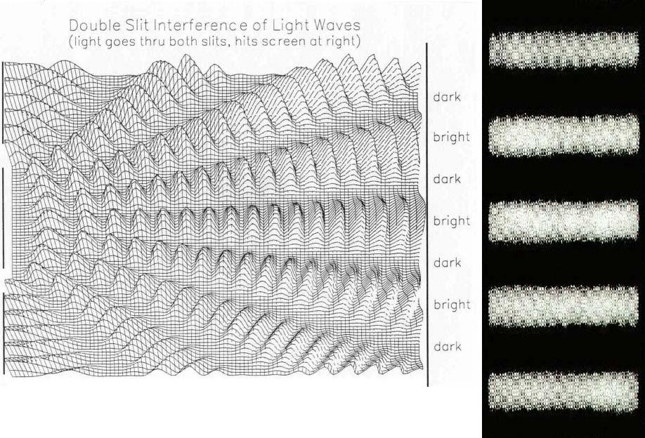
21 Interference of 2 Light Sources
22 Interference Patterns Constructive interference occurs at point P The two waves travel the same distance Therefore, they arrive in phase As a result, constructive interference occurs at this point and a bright fringe is observed
23 Interference Patterns The upper wave has to travel farther than the lower wave to reach point Q The upper wave travels one wavelength farther Therefore, the waves arrive in phase A second bright fringe occurs at this position
24 Interference Patterns The upper wave travels one-half of a wavelength farther than the lower wave to reach point R The trough of the bottom wave overlaps the crest of the upper wave This is destructive interference A dark fringe occurs
25

26 Diffraction depends on SLIT WIDTH: the smaller the width, relative to wavelength, the more bending and diffraction.

27
28 Double Slit is VERY IMPORTANT because it is evidence of waves. Only waves interfere like this.

29 If electron were hard bullets, there would be no interference pattern.

30 Particle Picture

31 In reality, electrons do show an interference pattern, like light waves.

32 Double Slit for Electrons shows Wave Interference

33 Electrons act like waves going through the slits but arrive at the detector like a particle.
34 Interference pattern builds one electron at a time. Electrons act like waves going through the slits but arrive at the detector like a particle.

35 Electron Diffraction


36 Particle Wave Duality
 The sources should be monochromatic Monochromatic means they have a single wavelength")
37 Conditions for Interference To observe interference in light waves, the following two conditions must be met: 1) The sources must be coherent They must maintain a constant phase with respect to each other 2) The sources should be monochromatic Monochromatic means they have a single wavelength
38 Double-Slit Assumptions Assumptions L >> d d >> λ a<< λ Approximation: θ is small and therefore the small angle approximation tan θ ~ sin θ can be used δ = r 2 r 1 = d sin θ y = L tan θ L sin θ Draw this! 2π 2π φ = δ = d sin θ λ λ
39 Young s Double-Slit Experiment: Geometry The path difference, δ, is found from the tan triangle δ = r 2 r 1 = d sin θ This assumes the paths are parallel Not exactly true, but a very good approximation if L is much greater than d 2π 2π φ = δ = d sin θ λ λ
40 Constructive Interference The path difference must be either zero or some integral multiple of the wavelength δ = d sin θ bright = mλ m = 0, ±1, ±2, m is called the order number When m = 0, it is the zeroth-order maximum When m = ±1, it is called the first-order maximum
41 Destructive Interference When destructive interference occurs, a dark fringe is observed This needs a path difference of an odd half wavelength δ = d sin θ dark = (m + ½)λ m = 0, ±1, ±2,
42 Interference Conditions Constructive: l l = mλ, m= 0,1,2,3, Destructive: l2 l1 = ( m+ ) λ, m= 0,1,2,3,... 2
43 Interference Fringes λ Bright fringe: sin θ = m m= 0,1,2,3,... d 1 λ Dark fringe: sin θ = ( m+ ) m= 0,1, 2,3,... 2 d Δl
44 Problem Red light (λ=664nm) is used in Young s double slit as shown. Find the distance y on the screen between the central bright fringe and the third order bright fringe. λ Bright fringe: sin θ = m m= 0,1,2,3,... d
45 Last Time: Fringe Equations For bright fringes λl ybright = m ( m = 0, ± 1, ± 2 K ) d For dark fringes λl 1 ydark = m+ ( m= 0, ± 1, ± 2 K ) d 2

46 Reality

47 Double Slit Interference Hyperphysics

48 Double Slit Interference Dependence on Slit Separation

49


50 Iridescence Diffraction & Interference
51 Thin Film Interference

52 Where does light actually come from? Light comes from the acceleration of charges.
53 Light is emitted when an electron in an atom jumps between energy levels either by excitation or collisions.


54 Atoms are EM Tuning Forks They are tuned to particular frequencies of light energy.

55 Atomic Emission of Light Each chemical element produces its own unique set of spectral lines when it burns


56 Hydrogen Spectra
57 Light Emission

58 Incandescent Light Bulb Full Spectrum of Light All frequencies excited!
59 Light Waves E = Emax cos (kx ωt) B = Bmax cos (kx ωt) Emax ω E = = = c B k B max I E B E cb = Sav = = = 2μ 2μ c 2μ 2 2 max max max max o o o I E 2 max
60 The Electromagnetic Spectrum
 to violet (λ ~4 x")
61 Visible Light Different wavelengths correspond to different colors The range is from red (λ ~ 7 x 10⁻⁷ m) to violet (λ ~4 x 10⁻⁷ m)


62 I am Watching YOU!!

63 Human Retina Sharp Spot: Fovea Blind Spot: Optic Nerve

64 Human Vision An optical Tuning Fork


65 Optical Antennae: Rods & Cones Rods: Intensity Cones: Color

66 If you pass white light through a prism, it separates into its component colors. long wavelengths R.O.Y. G. B.I.V spectrum short wavelengths
67 Radiation of Visible Sunlight

68 Additive Primary Colors Red, Green, Blue


69 RGB Color Theory
70 Additive Complementary Colors Yellow, Cyan, Magenta The color you have to add to get white light. Red + Green = Yellow Blue + Green = Cyan Red + Blue = Magenta Red + Blue + Green = White White light red light =?? White light yellow light =??

71 FYI: Mixing Colored Pigments Subtractive Colors Pigments subtract colors from white light. Yellow + Cyan = Green Cyan + Magenta = Purple Yellow + Magenta = Red Yellow + Cyan + Magenta = Black


72 Why are some materials colored? Colored materials absorb certain colors that resonate with their electron energy levels and reject & reflect those that do not.

73 Why is the Ocean Cyan? White light minus cyan is red. Ocean water absorbs red.


74 Thin Film Interference

75 Thin Films When reflecting off a medium of greater refractive index, a light wave undergoes a phase shift of ½ a wavelength. Wave 1 undergoes a phase shift of 180 degrees.

76 The Index of Refraction Refraction: Light Bends in Transmission The speed of light in any material is less than its speed in vacuum The index of refraction, n, of a medium can be defined as speed of light in a vacuum c n = speed of light in a medium v n λ λin vacuum = λn λin a medium For a vacuum, n = 1 We assume n = 1 for air also For other media, n > 1 n is a dimensionless number greater than unity, not necessarily an integer

77 Some Indices of Refraction

78 Following the Reflected and Refracted Rays Ray 1 is the incident ray Ray 2 is the reflected ray Ray 3 is refracted into the lucite Ray 4 is internally reflected in the lucite Ray 5 is refracted as it enters the air from the lucite

79 Index of Refraction Light may refract into a material where its speed is lower The angle of refraction is less than the angle of incidence The ray bends toward the normal n < n 1 2

80 Index of Refraction Light may refract into a material where its speed is higher The angle of refraction is greater than the angle of incidence The ray bends away from the normal n > n 1 2

81 Index of Refraction The path of the light through the refracting surface is reversible For example, a ray that travels from A to B If the ray originated at B, it would follow the line AB to reach point A
82 Interference in Thin Films Assume the light rays are traveling in air nearly normal to the two surfaces of the film Ray 1 undergoes a phase change of 180 with respect to the incident ray Ray 2, which is reflected from the lower surface, undergoes no phase change with respect to the incident wave
83 Phase Changes Due To Reflection An electromagnetic wave undergoes a phase change of 180 upon reflection from a medium of higher index of refraction than the one in which it was traveling Analogous to a pulse on a string reflected from a rigid support

84 Phase Changes Due To Reflection, cont. There is no phase change when the wave is reflected from a boundary leading to a medium of lower index of refraction Analogous to a pulse on a string reflecting from a free support
85 Interference in Thin Films An electromagnetic wave traveling from a medium of index of refraction n 1 toward a medium of index of refraction n 2 undergoes a 180 phase change on reflection when n 2 > n 1 There is no phase change in thereflected wave if n 2 < n 1
86 Interference in Thin Films Ray 2 also travels an additional distance of 2t before the waves recombine For constructive interference 2nt = (m + ½)λ (m = 0, 1, 2 ) This takes into account both the difference in optical path length for the two rays and the 180 phase change For destructive interference 2nt = mλ (m = 0, 1, 2 )
87 Interference in Thin Films Two factors influence interference Possible phase reversals on reflection Differences in travel distance The conditions are valid if the medium above the top surface is the same as the medium below the bottom surface If there are different media, these conditions are valid as long as the index of refraction for both is less than n
88 Interference in Thin Films If the thin film is between two different media, one of lower index than the film and one of higher index, the conditions for constructive and destructive interference are reversed With different materials on either side of the film, you may have a situation in which there is a 180 o phase change at both surfaces or at neither surface Be sure to check both the path length and the phase change
89 Problem Solving Strategy with Identify the thin film causing the interference The type of interference constructive or destructive that occurs is determined by the phase relationship between the upper and lower surfaces Thin Films

90 Problem Solving with Thin Films Phase differences have two causes differences in the distances traveled phase changes occurring on reflection Both causes must be considered when determining constructive or destructive interference The interference is constructive if the path difference is an integral multiple of λ and destructive if the path difference is an odd half multiple of λ

91
 from the reflected light. The refractive indices of the blue light in gasoline and water are 1.40 and 1.")
92 A thin film of gasoline floats on a puddle of water. Sunlight falls almost perpendicularly on the film and reflects into your eyes a yellow hue. Interference in the the thin gasoline film has eliminated blue (469nm in vacuum) from the reflected light. The refractive indices of the blue light in gasoline and water are 1.40 and 1.33 respectively. Determine the minimum nonzero thickness of the film.


93 Newton s Rings Interference Pattern
94 Newton s Rings Another method for viewing interference is to place a plano-convex lens on top of a flat glass surface The air film between the glass surfaces varies in thickness from zero at the point of contact to some thickness t A pattern of light and dark rings is observed These rings are called Newton s rings The particle model of light could not explain the origin of the rings Newton s rings can be used to test optical lenses

95 Light Waves E = Emax cos (kx ωt) B = Bmax cos (kx ωt) Emax ω E = = = c B k B max I E B E cb = Sav = = = 2μ 2μ c 2μ 2 2 max max max max o o o I E 2 max
96 Intensity Distribution, The total magnitude of the electric field at any point on the screen is the superposition of the two waves The magnitude of each wave at point P can be found E 1 = E o sin ωt E 2 = E o sin (ωt + φ) Both waves have the same amplitude, E o Electric Fields
97 Intensity Distribution, Phase Relationships The phase difference between the two waves at P depends on their path difference δ = r 2 r 1 = d sin θ A path difference of λ corresponds to a phase difference of 2π rad A path difference of δ is the same fraction of λ as the phase difference φ is of 2π This gives 2π 2π φ = δ = d sin θ λ λ
98 Intensity Distribution Resultant Field The magnitude of the resultant electric field comes from the superposition principle E P = E 1 + E 2 = E o [sin ωt + sin (ωt + φ)] This can also be expressed as φ φ EP = 2Eocos sin ωt E P has the same frequency as the light at the slits The magnitude of the field is multiplied by the factor 2 cos (φ / 2)
99 Intensity Distribution, Equation The expression for the intensity comes from the fact that the intensity of a wave is proportional to the square of the resultant electric field magnitude at that point The intensity therefore is 2 sin 2 I Imax cos πd θ Imax cos πd = y λ λl
100 Light Intensity, Graph The interference pattern consists of equally spaced fringes of equal intensity This result is valid only if L >> d and for small values of θ 2 sin 2 I Imax cos πd θ Imax cos πd = y λ λl
101 Phasor Addition of Waves, E 1 The sinusoidal wave can be represented graphically by a phasor of magnitude E o rotating about the origin counterclockwise with an angular frequency ω E 1 = E o sin ωt It makes an angle of ωt with the horizontal axis E 1 is the projection on the vertical axis
102 Phasor Addition of Waves, E 2 The second sinusoidal wave is E 2 = E o sin (ωt + φ) It has the same amplitude and frequency as E 1 Its phase is φ with respect to E 1
103 Phasor Addition of Waves, E R The resultant is the sum of E 1 and E 2 E R rotates with the same angular frequency ω The projection of E R along the vertical axis equals the sum of the projections of the other two vectors
104 E R at a Given Time From geometry at t = 0, E R = 2E 0 cos α = 2E o cos (φ / 2) The projection of E R along the vertical axis at any time t is φ EP = ERsin ωt + 2 φ φ = 2 Eo cos sin ωt + 2 2

105 Finding the Resultant of Several Waves Represent the waves by phasors Remember to maintain the proper phase relationship between one phasor and the next The resultant phasor E R is the vector sum of the individual phasors
106 Finding the Resultant of Several Waves, cont. At each instant, the projection of E R along the vertical axis represents the time variation of the resultant wave The phase angle α is between E R and the first phasor The resultant is given by the expression E P = E R sin (ωt + φ)
107 Phasor Diagrams for Two Coherent Sources, Comments E R is a maximum at φ = 0, 2π, 4π, The intensity is also a maximum at these points E R is zero at φ = π, 3π, The intensity is also zero at these points These results agree with the results obtained from other procedures

108 Phasor Diagrams for Two Coherent Sources
109 Three-Slit Interference Pattern Assume three equally spaced slits The fields are: E 1 = E o sin ωt E 2 = E o sin (ωt + φ) E 3 = E o sin (ωt + 2φ) Phasor diagrams can be used to find the resultant magnitude of the electric field
110 Three Slits Phasor Diagram The phasor diagram shows the electric field components and the resultant field The field at P has a maximum value of 3E o at φ = 0, ±2π, ± 4π... These points are called primary maxima
111 Three Slits, Additional Maxima The primary maxima occur when the phasors are in the same direction Secondary maxima occur when the wave from one slit exactly cancels the wave from another slit The field at P has a value of E o These points occur at φ = 0, ±π, ±3π...
112 Three Slits, Minima Total destructive interference occurs when the wave from all the slits form a closed triangle The field at P has a value of 0 These points occur at φ = 0, ±2π/3, ±4π/3...
113 Three Slits, Phasor Diagrams
114 Michelson Interferometer The interferometer was invented by an American physicist, A. A. Michelson The interferometer splits light into two parts and then recombines the parts to form an interference pattern The device can be used to measure wavelengths or other lengths with great precision
115 Michelson Interferometer, A ray of light is split into two rays by the mirror M o The mirror is at 45 o to the incident beam The mirror is called a beam splitter It transmits half the light and reflects the rest Schematic
116 Michelson Interferometer, Schematic Explanation, cont. The reflected ray goes toward mirror M 1 The transmitted ray goes toward mirror M 2 The two rays travel separate paths L 1 and L 2 After reflecting from M 1 and M 2, the rays eventually recombine at M o and form an interference pattern
117 Michelson Interferometer Operation The interference condition for the two rays is determined by their path length difference M 1 is moveable As it moves, the fringe pattern collapses or expands, depending on the direction M 1 is moved
118 Michelson Interferometer Operation, cont. The fringe pattern shifts by one-half fringe each time M 1 is moved a distance λ/4 The wavelength of the light is then measured by counting the number of fringe shifts for a given displacement of M 1
119 Michelson Interferometer Applications The Michelson interferometer was used to disprove the idea that the Earth moves through an ether Modern applications include Fourier Transform Infrared Spectroscopy (FTIR) Laser Interferometer Gravitational-Wave Observatory (LIGO)
120 Fourier Transform Infrared Spectroscopy This is used to create a high-resolution spectrum in a very short time interval The result is a complex set of data relating light intensity as a function of mirror position This is called an interferogram The interferogram can be analyzed by a computer to provide all of the wavelength components This process is called a Fourier transform
121 Laser Interferometer Gravitational-Wave Observatory General relativity predicts the existence of gravitational waves In Einstein s theory, gravity is equivalent to a distortion of space These distortions can then propagate through space The LIGO apparatus is designed to detect the distortion produced by a disturbance that passes near the Earth
122 LIGO, cont. The interferometer uses laser beams with an effective path length of several kilometers At the end of an arm of the interferometer, a mirror is mounted on a massive pendulum When a gravitational wave passes, the pendulum moves, and the interference pattern due to the laser beams from the two arms changes

123 LIGO in Richland, Washington
Chapter 37. Interference of Light Waves
 Chapter 37 Interference of Light Waves Wave Optics Wave optics is a study concerned with phenomena that cannot be adequately explained by geometric (ray) optics These phenomena include: Interference Diffraction
Chapter 37. Wave Optics
 Chapter 37 Wave Optics Wave Optics Wave optics is a study concerned with phenomena that cannot be adequately explained by geometric (ray) optics. Sometimes called physical optics These phenomena include:
Chapter 22 Wave Optics
 Chapter 22 Wave Optics Chapter Goal: To understand and apply the wave model of light. 2013 Pearson Education, Inc. Slide 22-2 2013 Pearson Education, Inc. Interference of Light Wave Optics Diffraction
Chapter 24. Wave Optics
 Chapter 24 Wave Optics Wave Optics The wave nature of light is needed to explain various phenomena Interference Diffraction Polarization The particle nature of light was the basis for ray (geometric) optics
Chapter 24. Wave Optics
 Chapter 24 Wave Optics hitt1 An upright object is located a distance from a convex mirror that is less than the mirror's focal length. The image formed by the mirror is (1) virtual, upright, and larger
Chapter 25. Wave Optics
 Chapter 25 Wave Optics Interference Light waves interfere with each other much like mechanical waves do All interference associated with light waves arises when the electromagnetic fields that constitute
Chapter 24. Wave Optics
 Chapter 24 Wave Optics Wave Optics The wave nature of light is needed to explain various phenomena Interference Diffraction Polarization The particle nature of light was the basis for ray (geometric) optics
Michelson Interferometer
 Michelson Interferometer The Michelson interferometer uses the interference of two reflected waves The third, beamsplitting, mirror is partially reflecting ( half silvered, except it s a thin Aluminum
Human Retina. Sharp Spot: Fovea Blind Spot: Optic Nerve
 Chapter 35 I am Watching YOU!! Human Retina Sharp Spot: Fovea Blind Spot: Optic Nerve Human Vision An optical Tuning Fork Optical Antennae: Rods & Cones Rods: Intensity Cones: Color Where does light actually
Textbook Reference: Physics (Wilson, Buffa, Lou): Chapter 24
: Chapter 24") AP Physics-B Physical Optics Introduction: We have seen that the reflection and refraction of light can be understood in terms of both rays and wave fronts of light. Light rays are quite compatible with
AP Physics-B Physical Optics Introduction: We have seen that the reflection and refraction of light can be understood in terms of both rays and wave fronts of light. Light rays are quite compatible with
specular diffuse reflection.
 Lesson 8 Light and Optics The Nature of Light Properties of Light: Reflection Refraction Interference Diffraction Polarization Dispersion and Prisms Total Internal Reflection Huygens s Principle The Nature
Chapter 8: Physical Optics
 Chapter 8: Physical Optics Whether light is a particle or a wave had puzzled physicists for centuries. In this chapter, we only analyze light as a wave using basic optical concepts such as interference
Human Retina. Sharp Spot: Fovea Blind Spot: Optic Nerve
 I am Watching YOU!! Human Retina Sharp Spot: Fovea Blind Spot: Optic Nerve Human Vision An optical Tuning Fork Optical Antennae: Rods & Cones Rods: Intensity Cones: Color Where does light actually come
Chapter 24 The Wave Nature of Light
 Chapter 24 The Wave Nature of Light 24.1 Waves Versus Particles; Huygens Principle and Diffraction Huygens principle: Every point on a wave front acts as a point source; the wavefront as it develops is
Interference of Light
 Interference of Light Review: Principle of Superposition When two or more waves interact they interfere. Wave interference is governed by the principle of superposition. The superposition principle says
Interference of Light
 Interference of Light Young s Double-Slit Experiment If light is a wave, interference effects will be seen, where one part of wavefront can interact with another part. One way to study this is to do a
f. (5.3.1) So, the higher frequency means the lower wavelength. Visible part of light spectrum covers the range of wavelengths from
 So, the higher frequency means the lower wavelength. Visible part of light spectrum covers the range of wavelengths from") Lecture 5-3 Interference and Diffraction of EM Waves During our previous lectures we have been talking about electromagnetic (EM) waves. As we know, harmonic waves of any type represent periodic process
Lecture 5-3 Interference and Diffraction of EM Waves During our previous lectures we have been talking about electromagnetic (EM) waves. As we know, harmonic waves of any type represent periodic process
Models of Light The wave model: The ray model: The photon model:
 Models of Light The wave model: under many circumstances, light exhibits the same behavior as sound or water waves. The study of light as a wave is called wave optics. The ray model: The properties of
Interference II: Thin Films
 Interference II: Thin Films Physics 2415 Lecture 36 Michael Fowler, UVa Today s Topics Colors of thin films Michelson s interferometer The Michelson Morley experiment Thin Film Interference Effects The
PHYSICS. Chapter 33 Lecture FOR SCIENTISTS AND ENGINEERS A STRATEGIC APPROACH 4/E RANDALL D. KNIGHT
 PHYSICS FOR SCIENTISTS AND ENGINEERS A STRATEGIC APPROACH 4/E Chapter 33 Lecture RANDALL D. KNIGHT Chapter 33 Wave Optics IN THIS CHAPTER, you will learn about and apply the wave model of light. Slide
Diffraction. Factors that affect Diffraction
 Diffraction What is one common property the four images share? Diffraction: Factors that affect Diffraction TELJR Publications 2017 1 Young s Experiment AIM: Does light have properties of a particle? Or
Reflections from a thin film
 Reflections from a thin film l Part of the wave reflects from the top surface and part from the bottom surface l The part that reflects from the top surface has a 180 o phase change while the part that
College Physics B - PHY2054C
 Young College - PHY2054C Wave Optics: 10/29/2014 My Office Hours: Tuesday 10:00 AM - Noon 206 Keen Building Outline Young 1 2 3 Young 4 5 Assume a thin soap film rests on a flat glass surface. Young Young
PY212 Lecture 25. Prof. Tulika Bose 12/3/09. Interference and Diffraction. Fun Link: Diffraction with Ace Ventura
 PY212 Lecture 25 Interference and Diffraction Prof. Tulika Bose 12/3/09 Fun Link: Diffraction with Ace Ventura Summary from last time The wave theory of light is strengthened by the interference and diffraction
College Physics 150. Chapter 25 Interference and Diffraction
 College Physics 50 Chapter 5 Interference and Diffraction Constructive and Destructive Interference The Michelson Interferometer Thin Films Young s Double Slit Experiment Gratings Diffraction Resolution
INTERFERENCE. where, m = 0, 1, 2,... (1.2) otherwise, if it is half integral multiple of wavelength, the interference would be destructive.
 otherwise, if it is half integral multiple of wavelength, the interference would be destructive.") 1.1 INTERFERENCE When two (or more than two) waves of the same frequency travel almost in the same direction and have a phase difference that remains constant with time, the resultant intensity of light
1.1 INTERFERENCE When two (or more than two) waves of the same frequency travel almost in the same direction and have a phase difference that remains constant with time, the resultant intensity of light
UNIT 102-9: INTERFERENCE AND DIFFRACTION
 Name St.No. - Date(YY/MM/DD) / / Section Group # UNIT 102-9: INTERFERENCE AND DIFFRACTION Patterns created by interference of light in a thin film. OBJECTIVES 1. Understand the creation of double-slit
EM Waves Practice Problems
 PSI AP Physics 2 Name 1. Sir Isaac Newton was one of the first physicists to study light. What properties of light did he explain by using the particle model? 2. Who was the first person who was credited
The sources must be coherent. This means they emit waves with a constant phase with respect to each other.
 CH. 24 Wave Optics The sources must be coherent. This means they emit waves with a constant phase with respect to each other. The waves need to have identical wavelengths. Can t be coherent without this.
5 10:00 AM 12:00 PM 1420 BPS
 Physics 294H l Professor: Joey Huston l email:huston@msu.edu l office: BPS3230 l Homework will be with Mastering Physics (and an average of 1 hand-written problem per week) I ve assigned 22.62 as a hand-in
22.4. (a) (b) (c) (d)
 (b) (c) (d)") mλl 22.2. Because ym = increasing λ and L increases the fringe spacing. Increasing d decreases the fringe d spacing. Submerging the experiment in water decreases λ and decreases the fringe spacing. So
mλl 22.2. Because ym = increasing λ and L increases the fringe spacing. Increasing d decreases the fringe d spacing. Submerging the experiment in water decreases λ and decreases the fringe spacing. So
Chapter 82 Example and Supplementary Problems
 Chapter 82 Example and Supplementary Problems Nature of Polarized Light: 1) A partially polarized beam is composed of 2.5W/m 2 of polarized and 4.0W/m 2 of unpolarized light. Determine the degree of polarization
UNIT VI OPTICS ALL THE POSSIBLE FORMULAE
 58 UNIT VI OPTICS ALL THE POSSIBLE FORMULAE Relation between focal length and radius of curvature of a mirror/lens, f = R/2 Mirror formula: Magnification produced by a mirror: m = - = - Snell s law: 1
Chapter 2: Wave Optics
 Chapter : Wave Optics P-1. We can write a plane wave with the z axis taken in the direction of the wave vector k as u(,) r t Acos tkzarg( A) As c /, T 1/ and k / we can rewrite the plane wave as t z u(,)
Interference. Electric fields from two different sources at a single location add together. The same is true for magnetic fields at a single location.
 Interference Electric fields from two different sources at a single location add together. The same is true for magnetic fields at a single location. Thus, interacting electromagnetic waves also add together.
Wallace Hall Academy
 Wallace Hall Academy CfE Higher Physics Unit 2 - Waves Notes Name 1 Waves Revision You will remember the following equations related to Waves from National 5. d = vt f = n/t v = f T=1/f They form an integral
Interference of Light Waves
 2.2 This is the Nearest One Head 1185 P U Z Z L E R The brilliant colors seen in peacock feathers are not caused by pigments in the feathers. If they are not produced by pigments, how are these beautiful
Wave Optics. April 11, 2014 Chapter 34 1
 Wave Optics April 11, 2014 Chapter 34 1 Announcements! Exam tomorrow! We/Thu: Relativity! Last week: Review of entire course, no exam! Final exam Wednesday, April 30, 8-10 PM Location: WH B115 (Wells Hall)
LECTURE 14 PHASORS & GRATINGS. Instructor: Kazumi Tolich
 LECTURE 14 PHASORS & GRATINGS Instructor: Kazumi Tolich Lecture 14 2 Reading chapter 33-5 & 33-8 Phasors n Addition of two harmonic waves n Interference pattern from multiple sources n Single slit diffraction
Chapter 35 &36 Physical Optics
 Chapter 35 &36 Physical Optics Physical Optics Phase Difference & Coherence Thin Film Interference 2-Slit Interference Single Slit Interference Diffraction Patterns Diffraction Grating Diffraction & Resolution
light Chapter Type equation here. Important long questions
 Type equation here. Light Chapter 9 Important long questions Q.9.1 Describe Young s double slit experiment for the demonstration of interference of. Derive an expression for fringe spacing? Ans. Young
Chapter 36. Diffraction. Dr. Armen Kocharian
 Chapter 36 Diffraction Dr. Armen Kocharian Diffraction Light of wavelength comparable to or larger than the width of a slit spreads out in all forward directions upon passing through the slit This phenomena
CHAPTER 26 INTERFERENCE AND DIFFRACTION
 CHAPTER 26 INTERFERENCE AND DIFFRACTION INTERFERENCE CONSTRUCTIVE DESTRUCTIVE YOUNG S EXPERIMENT THIN FILMS NEWTON S RINGS DIFFRACTION SINGLE SLIT MULTIPLE SLITS RESOLVING POWER 1 IN PHASE 180 0 OUT OF
Lecture 39. Chapter 37 Diffraction
 Lecture 39 Chapter 37 Diffraction Interference Review Combining waves from small number of coherent sources double-slit experiment with slit width much smaller than wavelength of the light Diffraction
CHAPTER 24 The Wave Nature of Light
 CHAPTER 24 The Wave Nature of Light http://www.physicsclassroom.com/class/light/lighttoc.html Units Waves Versus Particles; Huygens Principle and Diffraction Huygens Principle and the Law of Refraction
Light and Electromagnetic Waves. Honors Physics
 Light and Electromagnetic Waves Honors Physics Electromagnetic Waves EM waves are a result of accelerated charges and disturbances in electric and magnetic fields (Radio wave example here) As electrons
Chapter 15. Light Waves
 Chapter 15 Light Waves Chapter 15 is finished, but is not in camera-ready format. All diagrams are missing, but here are some excerpts from the text with omissions indicated by... After 15.1, read 15.2
Where n = 0, 1, 2, 3, 4
 Syllabus: Interference and diffraction introduction interference in thin film by reflection Newton s rings Fraunhofer diffraction due to single slit, double slit and diffraction grating Interference 1.
Chapter 38 Wave Optics (II)
") Chapter 38 Wave Optics (II) Initiation: Young s ideas on light were daring and imaginative, but he did not provide rigorous mathematical theory and, more importantly, he is arrogant. Progress: Fresnel,
Chapter 38 Wave Optics (II) Initiation: Young s ideas on light were daring and imaginative, but he did not provide rigorous mathematical theory and, more importantly, he is arrogant. Progress: Fresnel,
Control of Light. Emmett Ientilucci Digital Imaging and Remote Sensing Laboratory Chester F. Carlson Center for Imaging Science 8 May 2007
 Control of Light Emmett Ientilucci Digital Imaging and Remote Sensing Laboratory Chester F. Carlson Center for Imaging Science 8 May 007 Spectro-radiometry Spectral Considerations Chromatic dispersion
22.1. Visualize: Please refer to Figure Ex22.1. Solve: (a)
") 22.. Visualize: Please refer to Figure Ex22.. Solve: (a) (b) The initial light pattern is a double-slit interference pattern. It is centered behind the midpoint of the slits. The slight decrease in intensity
22.. Visualize: Please refer to Figure Ex22.. Solve: (a) (b) The initial light pattern is a double-slit interference pattern. It is centered behind the midpoint of the slits. The slight decrease in intensity
Waves & Oscillations
 Physics 42200 Waves & Oscillations Lecture 41 Review Spring 2016 Semester Matthew Jones Final Exam Date:Tuesday, May 3 th Time:7:00 to 9:00 pm Room: Phys 112 You can bring one double-sided pages of notes/formulas.
Chapter 38. Diffraction Patterns and Polarization
 Chapter 38 Diffraction Patterns and Polarization Diffraction Light of wavelength comparable to or larger than the width of a slit spreads out in all forward directions upon passing through the slit This
Lecture Wave Optics. Physics Help Q&A: tutor.leiacademy.org
 Lecture 1202 Wave Optics Physics Help Q&A: tutor.leiacademy.org Total Internal Reflection A phenomenon called total internal reflectioncan occur when light is directed from a medium having a given index
INTERFERENCE. (i) When the film is quite thin as compared to the wavelength of light,
 When the film is quite thin as compared to the wavelength of light,") (a) Reflected System: For the thin film in air the ray BG suffers reflection at air medium (rare to denser) boundary, it undergoes a phase change of π and a path change of λ/2, while the ray DF does not,
(a) Reflected System: For the thin film in air the ray BG suffers reflection at air medium (rare to denser) boundary, it undergoes a phase change of π and a path change of λ/2, while the ray DF does not,
Lecture PowerPoints. Chapter 24 Physics: Principles with Applications, 7 th edition Giancoli
 Lecture PowerPoints Chapter 24 Physics: Principles with Applications, 7 th edition Giancoli This work is protected by United States copyright laws and is provided solely for the use of instructors in teaching
25-1 Interference from Two Sources
 25-1 Interference from Two Sources In this chapter, our focus will be on the wave behavior of light, and on how two or more light waves interfere. However, the same concepts apply to sound waves, and other
Interference Effects. 6.2 Interference. Coherence. Coherence. Interference. Interference
 Effects 6.2 Two-Slit Thin film is a general property of waves. A condition for is that the wave source is coherent. between two waves gives characteristic patterns due to constructive and destructive.
Dr. Quantum. General Physics 2 Light as a Wave 1
 Dr. Quantum General Physics 2 Light as a Wave 1 The Nature of Light When studying geometric optics, we used a ray model to describe the behavior of light. A wave model of light is necessary to describe
Chapter 35. The Nature of Light and the Laws of Geometric Optics
 Chapter 35 The Nature of Light and the Laws of Geometric Optics Introduction to Light Light is basic to almost all life on Earth. Light is a form of electromagnetic radiation. Light represents energy transfer
Chapter 24. Wave Optics
 Chapter 24 Wave Optics Diffraction Huygen s principle requires that the waves spread out after they pass through slits This spreading out of light from its initial line of travel is called diffraction
To determine the wavelength of laser light using single slit diffraction
 9 To determine the wavelength of laser light using single slit diffraction pattern 91 Apparatus: Helium-Neon laser or diode laser, a single slit with adjustable aperture width, optical detector and power
Chapter 24 - The Wave Nature of Light
 Chapter 24 - The Wave Nature of Light Summary Four Consequences of the Wave nature of Light: Diffraction Dispersion Interference Polarization Huygens principle: every point on a wavefront is a source of
Physics 272 Lecture 27 Interference (Ch ) Diffraction (Ch )
 Diffraction (Ch )") Physics 272 Lecture 27 Interference (Ch 35.4-5) Diffraction (Ch 36.1-3) Thin Film Interference 1 2 n 0 =1 (air) t n 1 (thin film) n 2 Get two waves by reflection off of two different interfaces. Ray 2
Physics 272 Lecture 27 Interference (Ch 35.4-5) Diffraction (Ch 36.1-3) Thin Film Interference 1 2 n 0 =1 (air) t n 1 (thin film) n 2 Get two waves by reflection off of two different interfaces. Ray 2
Chapter 37. Interference of Light Waves
 Chapter 37 Interference of Light Waves C H A P T E R O U T L I N E 371 Conditions for Interference 372 Young s Double-Slit Experiment 373 Intensity Distribution of the Double-Slit Interference Pattern
Waves & Oscillations
 Physics 42200 Waves & Oscillations Lecture 42 Review Spring 2013 Semester Matthew Jones Final Exam Date:Tuesday, April 30 th Time:1:00 to 3:00 pm Room: Phys 112 You can bring two double-sided pages of
Unit 5.C Physical Optics Essential Fundamentals of Physical Optics
 Unit 5.C Physical Optics Essential Fundamentals of Physical Optics Early Booklet E.C.: + 1 Unit 5.C Hwk. Pts.: / 25 Unit 5.C Lab Pts.: / 20 Late, Incomplete, No Work, No Units Fees? Y / N 1. Light reflects
Basic optics. Geometrical optics and images Interference Diffraction Diffraction integral. we use simple models that say a lot! more rigorous approach
 Basic optics Geometrical optics and images Interference Diffraction Diffraction integral we use simple models that say a lot! more rigorous approach Basic optics Geometrical optics and images Interference
LECTURE 26: Interference ANNOUNCEMENT. Interference. Interference: Phase Differences
 ANNOUNCEMENT *Exam : Friday December 4, 0, 8 AM 0 AM *Location: Elliot Hall of Music *Covers all readings, lectures, homework from Chapters 9 through 33. *The exam will be multiple choice. Be sure to bring
Interference, Diffraction & Polarization
 Interference, Diffraction & Polarization PHY232 Remco Zegers zegers@nscl.msu.edu Room W109 cyclotron building http://www.nscl.msu.edu/~zegers/phy232.html light as waves so far, light has been treated as
Physical or wave optics
 Physical or wave optics In the last chapter, we have been studying geometric optics u light moves in straight lines u can summarize everything by indicating direction of light using a ray u light behaves
PHY132 Introduction to Physics II Class 5 Outline:
 PHY132 Introduction to Physics II Class 5 Outline: Ch. 22, sections 22.1-22.4 (Note we are skipping sections 22.5 and 22.6 in this course) Light and Optics Double-Slit Interference The Diffraction Grating
Diffraction Challenge Problem Solutions
 Diffraction Challenge Problem Solutions Problem 1: Measuring the Wavelength of Laser Light Suppose you shine a red laser through a pair of narrow slits (a = 40 μm) separated by a known distance and allow
Physics 1C Lecture 27A
 Physics 1C Lecture 27A "Any other situation in quantum mechanics, it turns out, can always be explained by saying, You remember the experiment with the two holes? It s the same thing. " --Richard Feynman
Intermediate Physics PHYS102
 Intermediate Physics PHYS102 Dr Richard H. Cyburt Assistant Professor of Physics My office: 402c in the Science Building My phone: (304) 384-6006 My email: rcyburt@concord.edu My webpage: www.concord.edu/rcyburt
DIFFRACTION 4.1 DIFFRACTION Difference between Interference and Diffraction Classification Of Diffraction Phenomena
 4.1 DIFFRACTION Suppose a light wave incident on a slit AB of sufficient width b, as shown in Figure 1. According to concept of rectilinear propagation of light the region A B on the screen should be uniformly
AH Division of Wavefront and Amplitude Answers
 AH Division of Wavefront and Amplitude Answers 1. Interference. 2. a) Splitting a single light beam into two beams, a reflected beam and a transmitted beam, at a surface between two media of two different
LECTURE 12 INTERFERENCE OF LIGHT. Instructor: Kazumi Tolich
 LECTURE 12 INTERFERENCE OF LIGHT Instructor: Kazumi Tolich Lecture 12 2 17.2 The interference of light Young s double-slit experiment Analyzing double-slit interference 17.3 The diffraction grating Spectroscopy
Physics 1C, Summer 2011 (Session 1) Practice Midterm 2 (50+4 points) Solutions
 Practice Midterm 2 (50+4 points) Solutions") Physics 1C, Summer 2011 (Session 1) Practice Midterm 2 (50+4 points) s Problem 1 (5x2 = 10 points) Label the following statements as True or False, with a one- or two-sentence explanation for why you chose
Physics 1C, Summer 2011 (Session 1) Practice Midterm 2 (50+4 points) s Problem 1 (5x2 = 10 points) Label the following statements as True or False, with a one- or two-sentence explanation for why you chose
Single slit diffraction
 Single slit diffraction Book page 364-367 Review double slit Core Assume paths of the two rays are parallel This is a good assumption if D >>> d PD = R 2 R 1 = dsin θ since sin θ = PD d Constructive interference
Topic 9: Wave phenomena - AHL 9.3 Interference
 Topic 9.3 is an extension of Topic 4.4. Essential idea: Interference patterns from multiple slits and thin films produce accurately repeatable patterns. Nature of science: (1) Curiosity: Observed patterns
Phy 133 Section 1: f. Geometric Optics: Assume the rays follow straight lines. (No diffraction). v 1 λ 1. = v 2. λ 2. = c λ 2. c λ 1.
. v 1 λ 1. = v 2. λ 2. = c λ 2. c λ 1.") Phy 133 Section 1: f Geometric Optics: Assume the rays follow straight lines. (No diffraction). Law of Reflection: θ 1 = θ 1 ' (angle of incidence = angle of reflection) Refraction = bending of a wave
Phy 133 Section 1: f Geometric Optics: Assume the rays follow straight lines. (No diffraction). Law of Reflection: θ 1 = θ 1 ' (angle of incidence = angle of reflection) Refraction = bending of a wave
AP Physics Problems -- Waves and Light
 AP Physics Problems -- Waves and Light 1. 1975-4 (Physical Optics) a. Light of a single wavelength is incident on a single slit of width w. (w is a few wavelengths.) Sketch a graph of the intensity as
MEASUREMENT OF THE WAVELENGTH WITH APPLICATION OF A DIFFRACTION GRATING AND A SPECTROMETER
 Warsaw University of Technology Faculty of Physics Physics Laboratory I P Irma Śledzińska 4 MEASUREMENT OF THE WAVELENGTH WITH APPLICATION OF A DIFFRACTION GRATING AND A SPECTROMETER 1. Fundamentals Electromagnetic
For more info
 Huygens Principle:- Wave-front of a wave, at any instant, is defined as the locus of all the particles in the medium which are being disturbed at the same instant of time and are in the same phase of vibration.
Diffraction. Introduction: Diffraction is bending of waves around an obstacle (barrier) or spreading of waves passing through a narrow slit.
 or spreading of waves passing through a narrow slit.") Introduction: Diffraction is bending of waves around an obstacle (barrier) or spreading of waves passing through a narrow slit. Diffraction amount depends on λ/a proportion If a >> λ diffraction is negligible
Introduction: Diffraction is bending of waves around an obstacle (barrier) or spreading of waves passing through a narrow slit. Diffraction amount depends on λ/a proportion If a >> λ diffraction is negligible
14 Chapter. Interference and Diffraction
 14 Chapter Interference and Diffraction 14.1 Superposition of Waves... 14-14.1.1 Interference Conditions for Light Sources... 14-4 14. Young s Double-Slit Experiment... 14-4 Example 14.1: Double-Slit Experiment...
Physics 214 Midterm Fall 2003 Form A
 1. A ray of light is incident at the center of the flat circular surface of a hemispherical glass object as shown in the figure. The refracted ray A. emerges from the glass bent at an angle θ 2 with respect
Chapter 24. Wave Optics. Wave Optics. The wave nature of light is needed to explain various phenomena
 Chapter 24 Wave Optics Wave Optics The wave nature of light is needed to explain various phenomena Interference Diffraction Polarization The particle nature of light was the basis for ray (geometric) optics
No Brain Too Small PHYSICS
 Level 3 Physics: Demonstrate understanding of Waves Waves Behaviour - Answers In 203, AS 9523 replaced AS 90520. The Mess that is NCEA Assessment Schedules. In AS 90520 there was an Evidence column with
MICHELSON S INTERFEROMETER
 MICHELSON S INTERFEROMETER Objectives: 1. Alignment of Michelson s Interferometer using He-Ne laser to observe concentric circular fringes 2. Measurement of the wavelength of He-Ne Laser and Na lamp using
Phase. E = A sin(2p f t+f) (wave in time) or E = A sin(2p x/l +f) (wave in space)
 (wave in time) or E = A sin(2p x/l +f) (wave in space)") Interference When two (or more) waves arrive at a point (in space or time), they interfere, and their amplitudes may add or subtract, depending on their frequency and phase. 1 Phase E = A sin(2p f t+f)
Interference When two (or more) waves arrive at a point (in space or time), they interfere, and their amplitudes may add or subtract, depending on their frequency and phase. 1 Phase E = A sin(2p f t+f)
New topic: Diffraction only one slit, but wide. From Last time. Huygen s principle. Overlapping diffraction patterns. Diffraction from other objects
 New topic: Diffraction only one slit, but wide From Last time Two-source interference: Interference-like pattern from a single slit. For a slit: a θ central width ~ 2 Diffraction grating Week3HW on Mastering
Physics Midterm I
 Phys121 - February 6, 2009 1 Physics 121 - Midterm I Last Name First Name Student Number Signature Tutorial T.A. (circle one): Ricky Chu Firuz Demir Maysam Emadi Alireza Jojjati Answer ALL 10 questions.
SNC 2PI Optics Unit Review /95 Name:
 SNC 2PI Optics Unit Review /95 Name: Part 1: True or False Indicate in the space provided if the statement is true (T) or false(f) [15] 1. Light is a form of energy 2. Shadows are proof that light travels
Fluids, Thermodynamics, Waves, & Optics Optics Lab 9 Interference and Diffraction
 Fluids, Thermodynamics, Waves, & Optics Optics Lab 9 Interference and Diffraction Lana Sheridan De Anza College Jun 13, 2018 Overview Purpose Theory interference from two coherent light sources diffraction
Electricity & Optics
 Physics 24100 Electricity & Optics Lecture 27 Chapter 33 sec. 7-8 Fall 2017 Semester Professor Koltick Clicker Question Bright light of wavelength 585 nm is incident perpendicularly on a soap film (n =
Lecture Ray Model of Light. Physics Help Q&A: tutor.leiacademy.org
 Lecture 1201 Ray Model of Light Physics Help Q&A: tutor.leiacademy.org Reflection of Light A ray of light, the incident ray, travels in a medium. When it encounters a boundary with a second medium, part
E x Direction of Propagation. y B y
 x E x Direction of Propagation k z z y B y An electromagnetic wave is a travelling wave which has time varying electric and magnetic fields which are perpendicular to each other and the direction of propagation,
Chapter 24. Wave Optics. Wave Optics. The wave nature of light is needed to explain various phenomena
 Chapter 24 Wave Optics Wave Optics The wave nature of light is needed to explain various phenomena Interference Diffraction Polarization The particle nature of light was the basis for ray (geometric) optics