2D & 3D CAD SOFTWARE USER MANUAL. AutoQ3D CAD for ipad & iphone
|
|
|
- Jonathan Dorsey
- 5 years ago
- Views:
Transcription

1 Type to enter text 2D & 3D CAD SOFTWARE USER MANUAL AutoQ3D CAD for ipad & iphone AUTOQ3D TEAM FIRST EDITION
2 AutoQ3D CAD for ipad & iphone 2D / 3D cad software user manual 2015 by AutoQ3D Team. All rights reserved. All registered trademarks belong to their respective owners. Apple, the Apple logo, iphone, ipod touch, and itunes are trademarks of Apple Inc., registered in the U.S. and other countries. ipad is a trademark of Apple Inc. App Store is a service mark of Apple Inc. All other product and service names mentioned are the trademarks of their respective companies. i
.")
3 CHAPTER 1 Introduction Drawings are still used to communicate ideas effectively but the tools are the things that have changed through time like CAD (Computer Assisted Design). AutoQ3D CAD for ipad and iphone is one of these tools that allows you to use the new mobile technology in your 2D and 3D designs.
4 SECTION 1 Overview Modification Tools Snapping Tools Grouping Tools Getting Started section is a good way to start using AutoQ3D CAD for ipad and iphone. AutoQ3D CAD for ipad and iphone is a 2D / 3D CAD application that runs on ios devices and available on the App Store ( Getting Help section is another way to look for more resources in this learning process. The application allows engineers, architects, technicals, game designers or any person with CAD interest to draw 2D / 3D models using simple and fast tools. It is designed to be a powerful but light CAD editor to create, edit and enhance your drawings without hassle with complex options you will never use. The program allows you draw in 2D and 3D dimensions with a convenient and intuitive workspace. When we talk about drawing in 3D dimension means to manage objects with use of X, Y and Z coordinates. AutoQ3D CAD for ipad and iphone offers you the following features: Preset Views Drawing Tools 3
5 SECTION 2 Getting Help Basic Video Tutorials Getting Started Guide ( v=eir6veccknk) Introduction to 3D CAD on ipad ( watch?v=zoqstw3wrek) AutoQ3D CAD for ipad and iphone have various ways to getting help about the application. Inside the application On the top of the application screen appears commands and their instructions, each command has options enclosed in brackets that you can access touching the information area. This helps you to go step by step in the process of each tool. Forums Here you will find many users posts about the use of the application, news and announcements. Support You can write us via (support@autoq3d.com). Getting Started Tutorial for ipad This Getting Started Tutorial is a step by step practice. you can find it here. Web You can find additional documentation here ( Social Media Currently we have presence on: Twitter ( Facebook ( YouTube ( 4

6 CHAPTER 2 Getting Started Now you are ready to start your learning. In this chapter you will learn basics and recurring tasks to draw efficiently as how to set points, how to use the second touch feature, select objects, move items, scale, stretch and apply textures.


7 SECTION 1 The User Interface YOU WILL LEARN 1. Identify the different user interface components. 1 Main menu bar. Here you ll see Draw, Modify, Group, Misc and other menu options. 2 Menu options. Here you ll find the menu tools. 3 Information area. Here you ll see the selected tools commands, parameters and general instructions as well. 4 Drawing area. Where you draw your models. 5 View button. This button sets you in view mode. 6 Button. General buttons that help you to change color, snap, properties and cancel commands. 7 User Coordinate System icon. Helps you to view a reference about the orientation plane your e working at. 6

8 SECTION 2 Setting specific points YOU WILL LEARN How to set points using the touching interface You are able to select a point using the touch in your ipad or iphone just moving the cursor with one finger and then without releasing your finger from the drawing area, tap the screen with another finger to select a point. We have called this feature as the second touch and it is useful to give precision when you are drawing. 1. How to set points using the touching interface. 2. How to set points typing directly with the virtual keyboard. 3. Type of values you can use with the virtual keyboard. 4. How to type absolute coordinates. 5. How to type relative coordinates. 7

9 How to set points typing directly with the virtual keyboard There is an area above the drawing area and immediately below the menu bar where the commands and its parameters are displayed. You can touch this section called the information area when some tool is asking for an input. Let s see an example: Select Draw > Line tool and then watch the information area where you can see that the command line is asking for the parameter pickpoint1. Touch the information area and then you will see a dialog that says value, tap it. Then type 2,2 and then tap OK button. 8
10 Type of values you can use with the virtual keyboard Here you can see some different type of value examples: EXAMPLE VALUE 1,0 DESCRIPTION If you are working in Z plane, then 1 is the value for the X axis and the 0 is the Y axis value. EXAMPLE VALUE DESCRIPTION 2,4.6 If you are working in Z plane, then 2 is the value for the X axis and the 4.6 is the Y axis value. 10 An integer value. This type of value is used in tools when they are asking for example number of copies, number of sides, etc. 0,2,0.3 Here 0 is the X axis value, 2 is the Y axis value and 0.3 is the Z axis value A decimal value. This type of value can be used for example to specify angles, height of text, circle radius, etc. 1.50r A value expressing an angle in radians. 23r d 32d20 8 A value expressing an angle in radians, minutes and seconds. A value expressing an angle in degrees. A value expressing an angle in degrees, minutes and seconds. You can also specify magnitude and angle: EXAMPLE VALUE 1<90 3.5<45 5<1.7r DESCRIPTION A polar coordinate that specify 1 unit of distance and 90 degrees (default) from origin (0,0). A polar coordinate that specify 3.5 units of distance and 45 degrees from origin (0,0). A polar coordinate that specify 5 units of distance and 1.7 radians from origin (0,0). Typing absolute coordinates When you know the exact coordinates of your point or its distance and angle from the 0,0 drawing origin, you can simply type the coordinates in one several formats as the following: 74<40d 10<2.2r <12d A polar coordinate that specify 74 units of distance and 40 degrees from origin (0,0). A polar coordinate that specify 10 units of distance 2.2 radians, 34 minutes and 36.5 from origin (0,0). A polar coordinate that specify 20 units of distance and 12 degrees, 23 minutes and seconds from origin (0,0). 9
11 Typing relative coordinates These types of coordinates are relative to the previous point. You can type directly the coordinates that is relative to the last point, just typing symbol before the first number, as the following: @0,2,1 DESCRIPTION Here the value for X axis is 0.97 and for the Y axis is 16, but relative to the last point. Here the value for X axis is 3 and for the Y axis is 5.6, relative to the last point. The value for the X axis is 0, Y axis is 2 and X axis is 1, relative to the last point. You can also specify magnitude and angle: DESCRIPTION 1 unit of distance and 90 degrees from the last point. 3.5 units of distance and 45 degrees from the last point. 12 units of distance and 2.1 radians from the last point. 52 units of distance and 32 degrees from the last point 10
12 SECTION 3 Using the second touch The second touch works as you were using the click of the mouse in your desktop programs. This is important because this add precision to your drawings in your ipad or iphone. YOU WILL LEARN 1. How to use the Second Touch feature. But let s see an example to explain how to use it: First we will draw a line. Go to Draw > Line tool Move your cursor with your finger in the spot where the line is going to start. 11

13 Then, without releasing your first finger, tap the screen with another finger. This select the starting point. Then move the cursor to start drawing a line. When you are satisfied with the position, just tap the screen with another finger, this is to select the second point of the line. 12

14 You can continue drawing lines using the same procedure described before; don t forget to tap the screen with another finger to finish the new line. When you have finished just press <Esc> button. 13
15 SECTION 4 Selecting objects To select objects you have to use the second touch feature described in Chapter 2 Section 3. Let s see an example. Move your cursor with one finger until the cursor grip touch the object. YOU WILL LEARN 1. How to select an object. 2. How to select multiple objects. Then, without releasing your finger, tap the drawing with another finger to select the object. To deselect an object just use the same procedure, move again your cursor over the selected object and without releasing your finger, tap the screen with other finger. Try it. 14
16 To select multiple objects, just select an area moving your cursor to the upper left corner of this area. Then, without releasing the finger, tap the drawing area with another finger to set the first point. Then, drag your cursor to below right corner and without releasing your finger, tap the screen with another finger to set the selection area that will select the objects inside. Try it. Note: the <Esc> button is used to cancel the current command and if you press it a second time it will unselect the objects. 15

17 SECTION 5 Moving objects To move objects, first move your cursor over the object. Select it using the second touch feature (section 3 and 4 of this chapter). You must see that some grips appear over the object. Try it. YOU WILL LEARN 1. How to move objects. 2. Use of the context menu. Move your cursor over some of the grips and without releasing this finger, tap the drawing area with another finger. You will notice that a context menu appears. Select the move option and move the object to desired position. Then without releasing your finger, tap the drawing area with another finger to set the new object position. 16
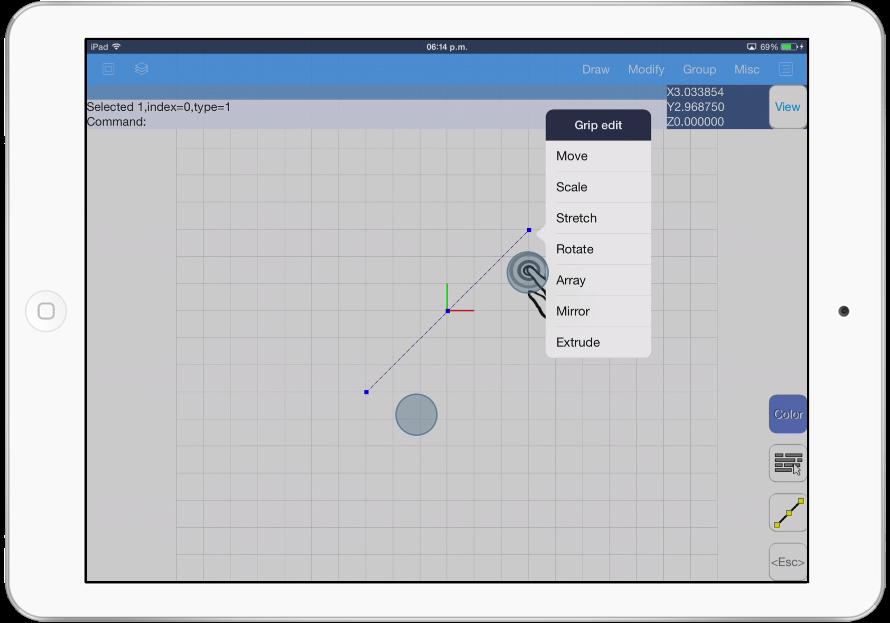
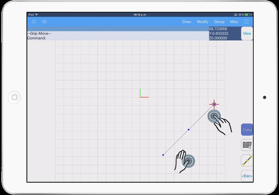
18 17

19 SECTION 6 Scaling objects To scale objects, first select the object(s). You will see some grips appear over the object. Then move your cursor over one of the grips and without releasing this finger, tap the drawing area with another finger. You will notice that a context menu appears. Select the Scale option. YOU WILL LEARN 1. How to scale an object. 2. How to use the context menu. 18

20 Now you are able to move the cursor up and down, meanwhile you do this you will notice how the objects scale up and down in the same manner. To apply the changes just tap again the drawing area or press <Esc> button if you want to cancel the command. 19
21 SECTION 7 Stretching objects In the example below, a rectangle will be stretched by moving on vertex to create an irregular shape. First select the two lines of the rectangle Then move the cursor to the vertex and tap the screen with another finger. A context menu appears Select the Stretch option. YOU WILL LEARN 1. How to stretch an object 2. How to use the context menu. Move down your cursor. Tap the screen with another finger to apply the changes or press <Esc> button to cancel. 20
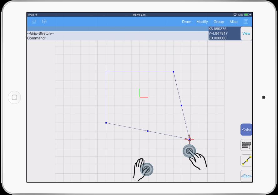
22 21
23 SECTION 8 Applying textures Texture files are images files you are able to apply them to objects. Currently AutoQ3D CAD for ipad and iphones supports these file formats to be used as textures: BMP JPG YOU WILL LEARN 1. Load textures files into your project. 2. How to apply texture file to an object. PNG To add files to your ipad or iphone you can use itunes software to load your image files to AutoQ3D CAD application. When you have the texture files on the application you can start applying to the objects. 22


24 The first step is to go to File -> Texture files option. Now you will see a button called Add texture that will help you to load up some images files. Select the image file and then tap on the apply button. In the following example you see a gray object that we will use to apply a texture on it. First select the object(s), then tap on Properties button Now look for Texture ID and tap the square button. Then select one of the texture images and last tap on the apply button. 23
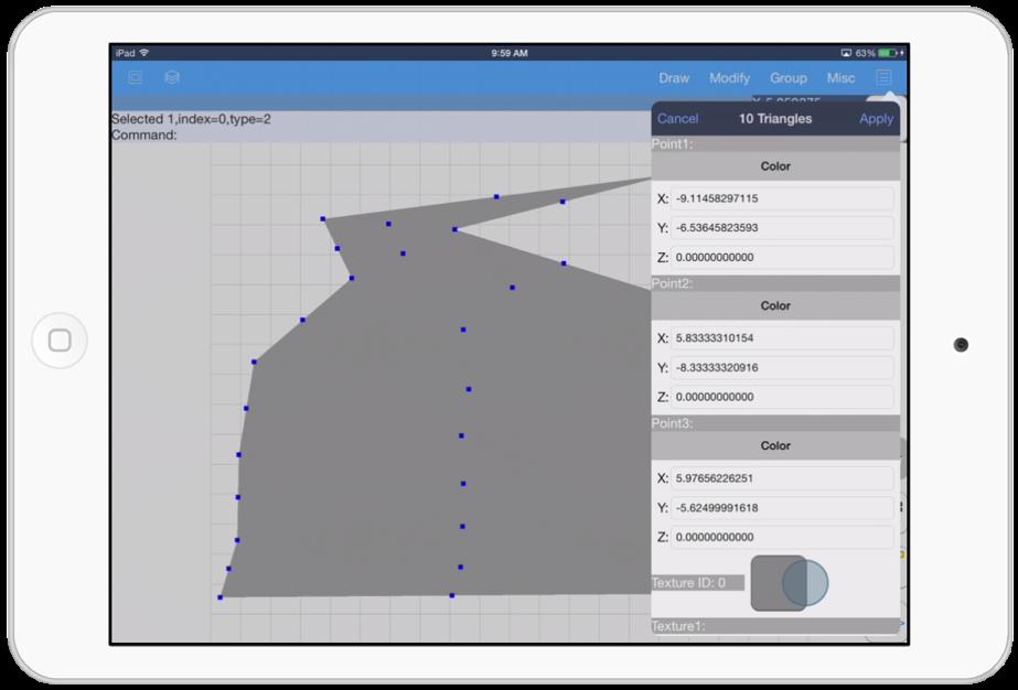

25 24

26 CHAPTER 3 Drawing Tools In this chapter you will learn the basic elements and tools to create 3D models. You can create models using three dimensions shapes such as lines, spheres, boxes, etc. Draw your own surfaces from 2D primitives using extrude and revolve.

27 SECTION 1 Line This tool draws one or more segments of a straight line. Each segment is an individual object. pickpoint 2. Specifies the end point of the line. Undo. This option allows you to undo the last line segment and return to the previous point. Next point. This allows you to continue drawing lines from the last ending point. Close. This option closes two or more lines segments of the line. A line is defined with a starting point and an ending point. The Line tool has these options: pickpoint 1. Specifies the first point of the line. 26

28 SECTION 2 Circle The Circle tool allows you to draw circles using different ways. interface or write the point coordinates. Choosing this option allows you to specify the circle radius or diameter. Radius. This option specifies the circle radius, you can use the touch interface to select a point or write a value. Diameter. This option specifies the circle diameter, you can use the touch interface to select a point or write a value. 3P. This option draws a circle selecting 3 points in the circumference. 2P. This option draws a circle selecting 2 points in the diameter. The Circle tool has these options: Specify center point. This option allows you to choose the central point of the circle. You can use the touch 27

29 SECTION 3 Rectangle This tool draws a rectangle specified by two corners. The Rectangle tool has these options: Specify first corner. Specifies the rectangle first corner, you can touch the screen to select a point or write a coordinate value. Specify second corner. Specifies the rectangle second corner, you can touch the screen to select a point or write a coordinate value. A rectangle is defined with 2 diagonal corners. 28

30 SECTION 4 Arc The Arc tool allows you to draw a circular arc. Center. This options allows you set a central point of the arc. Specify second point. This option allows you to set an arc point, but it is only available after you have set the starting point. Specify end-point. Specifies the arc end-point. Angle. This option is displayed only when you select Center option and it specifies the arc angle in degrees. The Arc tool has these options: Specify start point. This option allows you to choose the starting point of the arc. You can use the touch interface or write the point coordinates. 29


31 SECTION 5 Polygon Specify radius. This option draws the polygon from the center point to the polygon vertex. Poly segments. polygon will have. Specifies the number of sides that the This tool draws regular shapes with a specified number of sides. The Polygon tool has these options: Specify center. Specifies the center point of the polygon, you can use the touch interface or write a coordinate value. 30

32 SECTION 6 Text Height. This option specifies the text height selecting the default value or writing a new one. Set text. This option allows you to write the text string you want to insert. This tool creates text objects. The Text tool has these options: Specify point. Specifies the point where the text will be inserted. 31


33 SECTION 7 Triangles This tool draws a triangle surface. The Triangle tool has these options: pickpoint 1. Specifies the first point of the triangle. pickpoint 2. Specifies the second point of the triangle and allows you to close the triangle if you touch the cursor on screen. Undo. This option allows you to undo the last line segment and return to the previous point. Next point. This allows you to continue drawing triangles from the last ending point. Each triangle front surface is painted with a bright color and the back of each triangle surface is painted with a darker color. 32
. This option specifies the width of the box, you can use the touch interface to set the length or write a value directly.")
34 SECTION 8 Box This tool draws a three dimensional box. Box (Length). This option specifies the length of the box, you can use the touch interface to set the length or write a value directly. Box (Width). This option specifies the width of the box, you can use the touch interface to set the length or write a value directly. This option only appears if you wrote a single value on the Length option. Box (Height). This option specifies the height of the box, you can use the touch interface to set the length or write a value directly. The Box tool has these options: Box Position. Specifies the location point where the box will appear, you can use the touch interface or write the coordinates value directly. 33


35 SECTION 9 Sphere The Sphere tool creates a sphere. Sphere Detail Level. This option specifies a detail level, this value range from 1 to 6, where 6 means more detail. If you use values above 6 your system may experiment some delays because of the extreme detail used. Specify radius. This option specifies the sphere radius, you can use the touch interface to select a point or write a value. The Sphere tool has these options: Specify center. This option allows you to choose the central point of the sphere. Optionally you can set a detail level for the sphere. 34


36 SECTION 10 Region Select holes polygons. Specifies the polygon that will substract from the outer polygon. Finish. This option allows you to finish selecting objects. This tool creates a surface from the selected polygons. The Region tool has these options: Select outer polygon. Specifies the objects that limits the polygon. 35


37 SECTION 11 Extrude Just move your cursor on the screen to see how the object will extend. This tool creates a surface extending a line or a triangle surface. To use this tool just select the object and then select Draw- >Extrude menu or select one of the object grips and touch the screen, the Grip menu will appear with the extrude option. 36


38 SECTION 12 Revolve Revolve Segments. Specifies the number of segments of the final revolve object. Revolve Basepoint. It is the pivot point of the revolve. Revolve X. Select the X plane to revolve. This tool creates a surface object by sweeping it around an axis. Revolve Y. Select the Y plane to revolve. Revolve Z. Select the Z plane to revolve. The Revolve tool has these options: Revolve Angle. Specifies the revolve angle that the object will be swept. 37

39 CHAPTER 4 Modification Tools These tools will help you to edit 3D models using some basic operations. Trim, Fillet, Extend, Explode and Slice are some of these tools which are discussed in this chapter.

40 SECTION 1 Erase The Erase tool has these options: Select objects. Specifies the the object(s) that you want to delete from the drawing. Finish. This option allows you to finish selecting objects. This tool allows you to select an object or group of objects and delete them from the drawing. 39


41 SECTION 2 Snapline Note: to use the Snapline tool you have to apply it as an element of a group using the Group -> Edit mode. Another way to use Snapline tool is going to Properties menu and change the Snap property to a value of 1. Set the Snap property to a value of 1 to the selected lines to transform this line to a Snapline when it is grouped. These lines are used as end-point snap of groups. The Snapline tool allows you to customize any snap you want. To use Snapline tool just edit the group and draw the line(s), then select them and go to Modify -> Snapline option 40


42 41

43 SECTION 3 Round This tool allows to modify your selected object coordinates to round them to the decimals you specify. The Round tool has these parameters: Specify number of decimals. Specifies the number of decimals for the selected objects coordinates. 42

44 SECTION 4 Trim The Trim tool has these options: Select cutting edges. This option specifies the cutting edges. Select objects to trim. Specifies the objects to cut. This tool cuts objects sections that cross the selected cut edges. Finish. This option allows you to finish selecting objects. The Trim tool is like scissors that cut objects. 43
45 SECTION 5 Fillet The Fillet tool has these options: Select Lines. This option allows you to select the lines which a round corner will apply. Enter Radius. This option specifies the arc radius that will apply between the selected lines. This tool creates an arc between two lines. The Fillet tool rounds a corner. 44

46 SECTION 6 Offset Select side. Set the side where the parallel object will be located. Select item. Set the origin object item. This tool creates a parallel object to the selected item The Offset tool has these options: Select offset distance. Set the distance value from the selected item to draw the parallel object. 45
.")
47 SECTION 7 Extend Select object to extend. Specifies the object that will extend towards the boundary edge(s) Finish. This option allows you to finish selecting objects. This tool extends objects towards selected edges. The Extend tool has these options: Select Boundary edge(s). This option specifies the boundary edge(s). 46
48 SECTION 8 Explode This tool separate items from a group, in the case of circles/ arcs, it separates them in its lines segments. First select the object you want to convert, then apply the Explode option. The original figure now is configured into its lines segments. 47

49 SECTION 9 Slice Select slice plane, pickpoint 2. Specifies the end point of the line that it will do the cut. Select slice plane, Next point. Specifies another point to continue doing the cut. Undo. Undo the last command.. This tool cuts the selected object. The Slice tool has these options: Select slice plane, pickpoint 1. This option specifies starting point of the line that it will do the cut. 48

50 SECTION 10 Texture UV Spherical. Wraps the selected object with the texture using the normal information. XYZ to UV. Set the position coordinate as texture coordinate. This tool calculates the texture coordinates of the selected items. The Texture UV / Project tool has these parameters: The Texture UV tool menu has these options: Project. calculates the texture coordinates of selected items projecting the texture in a plane. Texture pick offset. This option set the texture position coordinate. scaleu. This option scales the texture width. scalev. This option scales the texture height. 49

51 The Texture UV / Spherical tool has these parameters: Texture Spherify. This action will set the texture around the sphere with an optional texture scale. <Skip>. This option take the default option and executes the command. Note: The Texture UV / XYZ to UV tool stretch the texture along an axis. 50


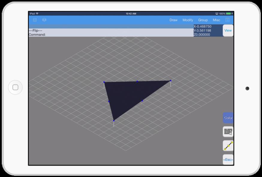
52 SECTION 11 Normals Switch. Modifies the points order, the texture coordinates, color and normals. The point 1 changes to point 3. The point 2 changes to point 1 and point 3 changes to point 2. Normals triangle. triangles surface. Set normals perpendicular to the The normals are the perpendiculars lines to the triangle face. Mean normals. Sums up normals of the points in common and then normalizes them. To make normals visible just tap VPort icon and activate checkbox Show Normals and change the Normal size to a value of 1 or greater. There is one normal for each triangle vertex. The Normals tool has these menu options: Flip. Turns the triangle side. 51
53 52

54 C HAPTER 5 Group Tools Organize objects by groups allows you to handle easier large 3D models. Grouping functions are useful to manage several objects as one entity simplifying the process of edit them.

55 SECTION 1 Group The Group tool allows you to select objects to join them as only one object. To use the Group tool just select the objects you want them joined and select the Group option from the Group menu. 54

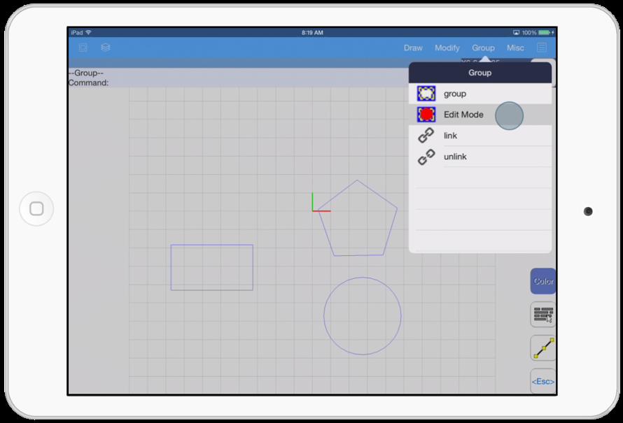
56 SECTION 2 Edit Mode The Edit mode option modifies the items inside the selected group. To quit the Edit mode just select the Edit mode option again, Note: the other groups will be hidden if the Edit mode is activated. 55
.")
57 SECTION 3 Link and Unlink Select Group (parent). Select the group which it will be attached to. Esc button. Exit the command applying the changes. This tool creates a link from one group to other group. The Unlink tool unlink the selected group from the link chain. The Link tool has these options: Select Group (child). Select the group which it will be attached to the parent. 56

58 CHAPTER 6 Misc Tools In this group of tools you will learn various functions that give us some drawing information or certain special commands. Tools like distance, area, distance text, angle text, perpendicular and tangent line are the some you will find in this chapter.
59 SECTION 1 Distance Distance pickpoint 2. Select the ending point to measure. Undo. Undo the last action. Note: the distance result between two points appears on the upper left corner of the screen. This tool determines the distance between two points. The Distance tool has these options: Distance pickpoint 1. Select the starting point to measure. 58
60 SECTION 2 Area Notes: The grouped polygon should be closed and if the group contains triangles, then shows the triangles area. The results appear on the upper left corner of screen and It shows area, perimeter and triangles area. This tool shows the area of a grouped polygon. The Area tool has these options: Select group with polygon. Just select the group with the polygon on screen to calculate the area. 59

61 SECTION 3 Origin Offset This tool changes the origin offset to a specified coordinate. The Origin Offset tool displays the next information when the command is executed: Current offset pickpoint. Displays the current offset. 60
 This tool creates a text inside your drawing with the distance of the selected object. Decimals. Set decimals number of the result. The Distance text tool has these options: Select line.")
62 SECTION 4 Distance text Specify point. Select your starting point where the text will be displayed. Height. Set text height. Format. Set text format in decimals (0.00) or feet/inches ( ) This tool creates a text inside your drawing with the distance of the selected object. Decimals. Set decimals number of the result. The Distance text tool has these options: Select line. Select the the line where distance will be measured. 61
 This tool creates a text that displays the angle of the selected arc. Radians. Set angle units to radians. Degree. Set angle units to degrees. The Angle text tool has these options: Select arc.")
63 SECTION 5 Angle text Specify point. Select your starting point where the text will be displayed. Height. Set text height. Format. Set text format in decimals (0.00) or degrees/ minutes/seconds (0d ) This tool creates a text that displays the angle of the selected arc. Radians. Set angle units to radians. Degree. Set angle units to degrees. The Angle text tool has these options: Select arc. Select the arc where the angle will be measured. 62

64 SECTION 6 Perpendicular Select line or circle/arc. Specifies the line, circle or arc where the perpendicular line will be drawn. This tool draws perpendicular lines to other lines. The Perpendicular tool has these options: pickpoint 1. This option specifies the first point of the perpendicular line. 63


65 SECTION 7 Tangent line This tool draws tangent lines to circles/arcs. The Tangent line tool has these options: Select circle/arc. This option specifies the circle or arc that will be tangent to the line. Point. Specifies the starting point of the tangent line. 64

66 CHAPTER 7 Other Options In this chapter we will see tools that help manage drawing and textures files.

67 SECTION 1 File Operations In this menu section you will find options related with your files Open. Open an existing drawing file on your device. Save. Store your existing drawing file on your device. Save as. Store your existing drawing file with the option to give a file name and a file type. Insert. This option allows you insert another drawing in your existing work. Texture files. Here you can manage your texture files. Send to. This option allows you to send your existing drawing to another person via , to another app or to the icloud. Get from. This option allows you to get a drawing file by icloud. The File menu has these options: New. Creates a new drawing file. 66
68 SECTION 2 Insert drawings The file types supported are: 3DQ AutoQ3D CAD native file format. DXF 2D file format and 3D face support. STL 3D file format triangles only. This option allows you to insert a drawing inside your existing drawing. OBJ 3D file format triangles only. 67

69 SECTION 3 Texture files Apply. Accept the changes in the texture files list to the project. This option allows you to manage image files to use them as textures in your drawings. The Texture files has the following actions: Add texture button. Add an image file to the project. Swipe. When you swipe over an element list you have the option to remove the image file from the project. 68
NAME ICON COMMAND SHORTCUT DESKTOP MOBILE DESCRIPTION Arc arc - Draw > Arc Draws any segment of a circle. - Inserts a camera object.
 List of Tools Drawing Tools Arc arc - Draw > Arc Draws any segment of a circle. Array array - Draw > Grip Copies objects in either a rectangular or polar Array Context Menu mode. Box box - Draw > Box Draws
Modeling a Gear Standard Tools, Surface Tools Solid Tool View, Trackball, Show-Hide Snaps Window 1-1
 Modeling a Gear This tutorial describes how to create a toothed gear. It combines using wireframe, solid, and surface modeling together to create a part. The model was created in standard units. To begin,
3ds Max Cottage Step 1. Always start out by setting up units: We re going with this setup as we will round everything off to one inch.
 3ds Max Cottage Step 1 Always start out by setting up units: We re going with this setup as we will round everything off to one inch. File/Import the CAD drawing Be sure Files of Type is set to all formats
GDL Toolbox 2 Reference Manual
 Reference Manual Archi-data Ltd. Copyright 2002. New Features Reference Manual New Save GDL command Selected GDL Toolbox elements can be exported into simple GDL scripts. During the export process, the
Module 1: Basics of Solids Modeling with SolidWorks
 Module 1: Basics of Solids Modeling with SolidWorks Introduction SolidWorks is the state of the art in computer-aided design (CAD). SolidWorks represents an object in a virtual environment just as it exists
Autodesk Fusion 360: Model. Overview. Modeling techniques in Fusion 360
 Overview Modeling techniques in Fusion 360 Modeling in Fusion 360 is quite a different experience from how you would model in conventional history-based CAD software. Some users have expressed that it
3D Body. Summary. Modified by Admin on Sep 13, Parent page: Objects
 3D Body Old Content - visit altium.com/documentation Modified by Admin on Sep 13, 2017 Parent page: Objects A sphere, a cylinder and 4 extruded rectangles have been used to create the 3D body for an LED.
Tutorial 3: Constructive Editing (2D-CAD)
") (2D-CAD) The editing done up to now is not much different from the normal drawing board techniques. This section deals with commands to copy items we have already drawn, to move them and to make multiple
(2D-CAD) The editing done up to now is not much different from the normal drawing board techniques. This section deals with commands to copy items we have already drawn, to move them and to make multiple
7/21/2009. Chapters Learning Objectives. Fillet Tool
 Chapters 12-13 JULY 21, 2009 Learning Objectives Chapter 12 Chapter 13 Use the FILLET tool to draw fillets, rounds, and other rounded corners. Place chamfers and angled corners with the CHAMFER tool. Separate
Properties of a Circle Diagram Source:
 Properties of a Circle Diagram Source: http://www.ricksmath.com/circles.html Definitions: Circumference (c): The perimeter of a circle is called its circumference Diameter (d): Any straight line drawn
Inventor 201. Work Planes, Features & Constraints: Advanced part features and constraints
 Work Planes, Features & Constraints: 1. Select the Work Plane feature tool, move the cursor to the rim of the base so that inside and outside edges are highlighted and click once on the bottom rim of the
Exercise Guide. Published: August MecSoft Corpotation
 VisualCAD Exercise Guide Published: August 2018 MecSoft Corpotation Copyright 1998-2018 VisualCAD 2018 Exercise Guide by Mecsoft Corporation User Notes: Contents 2 Table of Contents About this Guide 4
Structural & Thermal Analysis Using the ANSYS Workbench Release 12.1 Environment
 ANSYS Workbench Tutorial Structural & Thermal Analysis Using the ANSYS Workbench Release 12.1 Environment Kent L. Lawrence Mechanical and Aerospace Engineering University of Texas at Arlington SDC PUBLICATIONS
S206E Lecture 3, 5/15/2017, Rhino 2D drawing an overview
 Copyright 2017, Chiu-Shui Chan. All Rights Reserved. S206E057 Spring 2017 Rhino 2D drawing is very much the same as it is developed in AutoCAD. There are a lot of similarities in interface and in executing
TRAINING SESSION Q2 2016
 There are 8 main topics in this training session which focus on the Sketch tools in IRONCAD. Content Sketch... 2 3D Scene Background Settings... 3 Creating a new empty Sketch... 4 Foam with cut out for
Lesson 1: Creating T- Spline Forms. In Samples section of your Data Panel, browse to: Fusion 101 Training > 03 Sculpt > 03_Sculpting_Introduction.
 3.1: Sculpting Sculpting in Fusion 360 allows for the intuitive freeform creation of organic solid bodies and surfaces by leveraging the T- Splines technology. In the Sculpt Workspace, you can rapidly
Generating Vectors Overview
 Generating Vectors Overview Vectors are mathematically defined shapes consisting of a series of points (nodes), which are connected by lines, arcs or curves (spans) to form the overall shape. Vectors can
Excerpt from "Inside CorelCAD" - Windows edition To purchase the full book, please go to
 chapter 3 CAD Concepts 37 1. Start any drawing command, such as Line. : line Specify start point» (Move cursor.) 2. Right-click the coordinate field. Notice the short cut menu. 3. Choose Relative. (The
QuickTutor. An Introductory SilverScreen Modeling Tutorial. Solid Modeler
 QuickTutor An Introductory SilverScreen Modeling Tutorial Solid Modeler TM Copyright Copyright 2005 by Schroff Development Corporation, Shawnee-Mission, Kansas, United States of America. All rights reserved.
3 AXIS STANDARD CAD. BobCAD-CAM Version 28 Training Workbook 3 Axis Standard CAD
 3 AXIS STANDARD CAD This tutorial explains how to create the CAD model for the Mill 3 Axis Standard demonstration file. The design process includes using the Shape Library and other wireframe functions
Feature-based CAM software for mills, multi-tasking lathes and wire EDM. Getting Started
 Feature-based CAM software for mills, multi-tasking lathes and wire EDM www.featurecam.com Getting Started FeatureCAM 2015 R3 Getting Started FeatureCAM Copyright 1995-2015 Delcam Ltd. All rights reserved.
SolidWorks Intro Part 1b
 SolidWorks Intro Part 1b Dave Touretzky and Susan Finger 1. Create a new part We ll create a CAD model of the 2 ½ D key fob below to make on the laser cutter. Select File New Templates IPSpart If the SolidWorks
VERO UK TRAINING MATERIAL
 VERO UK TRAINING MATERIAL VISI Basic 2-D Modelling course (V-16) VISI Modelling 2D Design Introduction Many component designs follow a similar route, beginning with a 2D design, part modelled using solids
Google SketchUp. and SketchUp Pro 7. The book you need to succeed! CD-ROM Included! Kelly L. Murdock. Master SketchUp Pro 7 s tools and features
 CD-ROM Included! Free version of Google SketchUp 7 Trial version of Google SketchUp Pro 7 Chapter example files from the book Kelly L. Murdock Google SketchUp and SketchUp Pro 7 Master SketchUp Pro 7 s
Alibre Design Tutorial - Simple Revolve Translucent Glass Lamp Globe
 Alibre Design Tutorial - Simple Revolve Translucent Glass Lamp Globe Part Tutorial Exercise 2: Globe-1 In this Exercise, We will set System Parameters first. Then, in sketch mode, we will first Outline
Introduction Make a plan with tool Rectangle Measurements Toolbar Enter Return Measurements Toolbar Measure Protractor
 Introduction Open SketchUp, and an empty file appears. You are looking at the red-green plane, and the blue axis (vertical) is pointing toward you. By default, you are in the Line tool, as indicated by
An Approach to Content Creation for Trainz
 An Approach to Content Creation for Trainz Paul Hobbs Part 6 GMax Basics (Updates and sample files available from http://www.44090digitalmodels.de) Page 1 of 18 Version 3 Index Foreward... 3 The Interface...
Visual 2012 Help Index
 Visual 2012 Help Index Absolute Coordinates 2.1 Cartesian Coordinates Aim 7.4.3 Place and Aim Luminaires 7.4.4 Reaiming Luminaires Align Cursor and Plane to Current View 9.6 Align to View Align Cursor
A Comprehensive Introduction to SolidWorks 2011
 A Comprehensive Introduction to SolidWorks 2011 Godfrey Onwubolu, Ph.D. SDC PUBLICATIONS www.sdcpublications.com Schroff Development Corporation Chapter 2 Geometric Construction Tools Objectives: When
SOLIDWORKS 2016 and Engineering Graphics
 SOLIDWORKS 2016 and Engineering Graphics An Integrated Approach Randy H. Shih SDC PUBLICATIONS Better Textbooks. Lower Prices. www.sdcpublications.com Powered by TCPDF (www.tcpdf.org) Visit the following
Revit Architecture 2015 Basics
 Revit Architecture 2015 Basics From the Ground Up Elise Moss Authorized Author SDC P U B L I C AT I O N S Better Textbooks. Lower Prices. www.sdcpublications.com Powered by TCPDF (www.tcpdf.org) Visit
12 m. 30 m. The Volume of a sphere is 36 cubic units. Find the length of the radius.
 NAME DATE PER. REVIEW #18: SPHERES, COMPOSITE FIGURES, & CHANGING DIMENSIONS PART 1: SURFACE AREA & VOLUME OF SPHERES Find the measure(s) indicated. Answers to even numbered problems should be rounded
3D ModelingChapter1: Chapter. Objectives
 Chapter 1 3D ModelingChapter1: The lessons covered in this chapter familiarize you with 3D modeling and how you view your designs as you create them. You also learn the coordinate system and how you can
3D Design with 123D Design
 3D Design with 123D Design Introduction: 3D Design involves thinking and creating in 3 dimensions. x, y and z axis Working with 123D Design 123D Design is a 3D design software package from Autodesk. A
Speedway. Body. (S) on the Sketch toolbar. Fig. 1
 on the Sketch toolbar. Fig. 1") Chapter 1 A. New Part. Step 1. Click File Menu > New. Speedway Body Step 2. Click Part from the list and click OK, Fig. 1. B. Sketch Construction Rectangle. Step 1. Click Right Plane in the Feature Manager
Chapter 1 A. New Part. Step 1. Click File Menu > New. Speedway Body Step 2. Click Part from the list and click OK, Fig. 1. B. Sketch Construction Rectangle. Step 1. Click Right Plane in the Feature Manager
3D Modeling and Design Glossary - Beginner
 3D Modeling and Design Glossary - Beginner Align: to place or arrange (things) in a straight line. To use the Align tool, select at least two objects by Shift left-clicking on them or by dragging a box
SolidWorks 2½D Parts
 SolidWorks 2½D Parts IDeATe Laser Micro Part 1b Dave Touretzky and Susan Finger 1. Create a new part In this lab, you ll create a CAD model of the 2 ½ D key fob below to make on the laser cutter. Select
The Villa Savoye ( ), Poisy, Paris.
, Poisy, Paris.") Learning SketchUp Villa Savoye This tutorial will involve modeling the Villa Savoye by Le Corbusier Files needed to complete this tutorial are available in Mr. Cochran s Web Site The Villa Savoye (1929-1931),
Learning SketchUp Villa Savoye This tutorial will involve modeling the Villa Savoye by Le Corbusier Files needed to complete this tutorial are available in Mr. Cochran s Web Site The Villa Savoye (1929-1931),
Randy H. Shih. Jack Zecher PUBLICATIONS
 Randy H. Shih Jack Zecher PUBLICATIONS WWW.SDCACAD.COM AutoCAD LT 2000 MultiMedia Tutorial 1-1 Lesson 1 Geometric Construction Basics! " # 1-2 AutoCAD LT 2000 MultiMedia Tutorial Introduction Learning
User Guide. for. JewelCAD Professional Version 2.0
 User Guide Page 1 of 121 User Guide for JewelCAD Professional Version 2.0-1 - User Guide Page 2 of 121 Table of Content 1. Introduction... 7 1.1. Purpose of this document... 7 2. Launch JewelCAD Professional
BobCAD-CAM FAQ #50: How do I use a rotary 4th axis on a mill?
 BobCAD-CAM FAQ #50: How do I use a rotary 4th axis on a mill? Q: I ve read FAQ #46 on how to set up my milling machine. How do I enable 4th axis to actually use it? A: Enabling 4th axis in the machine
The Rectangular Problem
 C h a p t e r 2 The Rectangular Problem In this chapter, you will cover the following to World Class standards: The tools for simple 2D Computer Aided Drafting (CAD) The Command Line and the Tray The Line
SolidWorks 2013 and Engineering Graphics
 SolidWorks 2013 and Engineering Graphics An Integrated Approach Randy H. Shih SDC PUBLICATIONS Schroff Development Corporation Better Textbooks. Lower Prices. www.sdcpublications.com Visit the following
Autodesk Fusion 360 Training: The Future of Making Things Attendee Guide
 Autodesk Fusion 360 Training: The Future of Making Things Attendee Guide Abstract After completing this workshop, you will have a basic understanding of editing 3D models using Autodesk Fusion 360 TM to
Beginning Tutorial the Lego
 Beginning Tutorial the Lego In this tutorial, you will construct a simple hollowed-out block with a hole in it (looks like a Lego). You will learn the basics of creating and modifying sketches and features.
SketchUp Tool Basics
 SketchUp Tool Basics Open SketchUp Click the Start Button Click All Programs Open SketchUp Scroll Down to the SketchUp 2013 folder Click on the folder to open. Click on SketchUp. Set Up SketchUp (look
How to create shapes. Drawing basic shapes. Adobe Photoshop Elements 8 guide
 How to create shapes With the shape tools in Adobe Photoshop Elements, you can draw perfect geometric shapes, regardless of your artistic ability or illustration experience. The first step to drawing shapes
The Department of Construction Management and Civil Engineering Technology CMCE-1110 Construction Drawings 1 Lecture Introduction to AutoCAD What is
 The Department of Construction Management and Civil Engineering Technology CMCE-1110 Construction Drawings 1 Lecture Introduction to AutoCAD What is AutoCAD? The term CAD (Computer Aided Design /Drafting)
Skateboard. Hanger. in the Feature Manager and click Sketch. (S) on the Sketch. Line
 on the Sketch. Line") Chapter 3 Skateboard Hanger A. Sketch 1. Step 1. Click File Menu > New, click Part Metric and OK. Step 2. Click Right Plane from the Content toolbar, Fig. 1. in the Feature Manager and click Sketch Step
Chapter 3 Skateboard Hanger A. Sketch 1. Step 1. Click File Menu > New, click Part Metric and OK. Step 2. Click Right Plane from the Content toolbar, Fig. 1. in the Feature Manager and click Sketch Step
EZ-Mill EXPRESS TUTORIAL 2. Release 13.0
 E-Mill EPRESS TUTORIAL 2 Release 13.0 Copyright Notice This manual describes software that contains published and unpublished works of authorship proprietary to ECAM Solutions, Inc. It is made available
Tutorial Second Level
 AutoCAD 2018 Tutorial Second Level 3D Modeling Randy H. Shih SDC PUBLICATIONS Better Textbooks. Lower Prices. www.sdcpublications.com Powered by TCPDF (www.tcpdf.org) Visit the following websites to learn
SOLIDWORKS 2016: A Power Guide for Beginners and Intermediate Users
 SOLIDWORKS 2016: A Power Guide for Beginners and Intermediate Users The premium provider of learning products and solutions www.cadartifex.com Table of Contents Dedication... 3 Preface... 15 Part 1. Introducing
Beaumont Middle School Design Project April May 2014 Carl Lee and Craig Schroeder
 Beaumont Middle School Design Project April May 2014 Carl Lee and Craig Schroeder 1 2 SketchUp 1. SketchUp is free, and you can download it from the website www.sketchup.com. For some K12 use, see www.sketchup.com/3dfor/k12-education.
Lesson 1 Parametric Modeling Fundamentals
 1-1 Lesson 1 Parametric Modeling Fundamentals Create Simple Parametric Models. Understand the Basic Parametric Modeling Process. Create and Profile Rough Sketches. Understand the "Shape before size" approach.
Vectorworks Essential Tutorial Manual by Jonathan Pickup. Sample
 Vectorworks Essential Tutorial Manual by Jonathan Pickup Table of Contents 0.0 Introduction... iii 0.1 How to Use this Manual... iv 0.2 Real World Sizes... iv 0.3 New Ways of Drawing... v 1.0 Introduction
Structural & Thermal Analysis using the ANSYS Workbench Release 11.0 Environment. Kent L. Lawrence
 ANSYS Workbench Tutorial Structural & Thermal Analysis using the ANSYS Workbench Release 11.0 Environment Kent L. Lawrence Mechanical and Aerospace Engineering University of Texas at Arlington SDC PUBLICATIONS
ME009 Engineering Graphics and Design CAD 1. 1 Create a new part. Click. New Bar. 2 Click the Tutorial tab. 3 Select the Part icon. 4 Click OK.
 PART A Reference: SolidWorks CAD Student Guide 2014 2 Lesson 2: Basic Functionality Active Learning Exercises Creating a Basic Part Use SolidWorks to create the box shown at the right. The step-by-step
Skateboard. Hanger. in the Feature Manager and click Sketch on the Context toolbar, Fig. 1. Fig. 2
 Chapter 3 Skateboard Hanger A. Sketch1 Lines. Step 1. Click File Menu > New, click Part Metric and OK. Step 2. Click Right Plane in the Feature Manager and click Sketch on the Context toolbar, Fig. 1.
Module 4A: Creating the 3D Model of Right and Oblique Pyramids
 Inventor (5) Module 4A: 4A- 1 Module 4A: Creating the 3D Model of Right and Oblique Pyramids In Module 4A, we will learn how to create 3D solid models of right-axis and oblique-axis pyramid (regular or
Parametric Modeling. With. Autodesk Inventor. Randy H. Shih. Oregon Institute of Technology SDC PUBLICATIONS
 Parametric Modeling With Autodesk Inventor R10 Randy H. Shih Oregon Institute of Technology SDC PUBLICATIONS Schroff Development Corporation www.schroff.com www.schroff-europe.com 2-1 Chapter 2 Parametric
Rhinoceros NURBS modeling for Windows. Version 1.0 Training Manual Level 1
 Rhinoceros NURBS modeling for Windows Version 1.0 Training Manual Level 1 rhinolevel 1.doc Robert McNeel & Associates 1997. All Rights Reserved. Printed in U.S.A. Copyright by Robert McNeel & Associates.
Feature-Based Modeling and Optional Advanced Modeling. ENGR 1182 SolidWorks 05
 Feature-Based Modeling and Optional Advanced Modeling ENGR 1182 SolidWorks 05 Today s Objectives Feature-Based Modeling (comprised of 2 sections as shown below) 1. Breaking it down into features Creating
Licom Systems Ltd., Training Course Notes. 3D Surface Creation
 , Training Course Notes Work Volume and Work Planes...........................1 Overview..........................................1 Work Volume....................................1 Work Plane......................................1
Autodesk Inventor 2019 and Engineering Graphics
 Autodesk Inventor 2019 and Engineering Graphics An Integrated Approach Randy H. Shih SDC PUBLICATIONS Better Textbooks. Lower Prices. www.sdcpublications.com Powered by TCPDF (www.tcpdf.org) Visit the
Lesson 5 Solid Modeling - Constructive Solid Geometry
 AutoCAD 2000i Tutorial 5-1 Lesson 5 Solid Modeling - Constructive Solid Geometry Understand the Constructive Solid Geometry Concept. Create a Binary Tree. Understand the basic Boolean Operations. Create
CO2 Rail Car. Wheel Rear Px. on the Command Manager toolbar.
 Chapter 6 CO2 Rail Car Wheel Rear Px A. Sketch Construction Lines. Step 1. Click File Menu > New, click Part Metric and OK. Step 2. Click Front (plane) in the Feature Manager (left panel), Fig. 1. Step
Fixed Perimeter Rectangles Geometry Creating a Document
 Activity Overview: This activity provides the steps to create a TI-Nspire document that will be used to investigate side length and area in a rectangle with a fixed perimeter. An algebraic approach is
On the ribbon bar, click the Select from Sketch button.
 On the Features toolbar, click the Revolved Protrusion command. On the ribbon bar, click the Select from Sketch button. In the part window, select the Sketch, and on the ribbon bar click the Accept button.
AutoCADD Tutorial A survival guide
 AutoCADD Tutorial A survival guide Avery S.H. Copeland Prepared for IMDL Lab students and MIL volunteers October 9, 1997 Revised April 17, 1998 AutoCADD Tutorial Page 2 Contents Introduction Relative Coordinates
SOLIDWORKS: Lesson III Patterns & Mirrors. UCF Engineering
 SOLIDWORKS: Lesson III Patterns & Mirrors UCF Engineering Solidworks Review Last lesson we discussed several more features that can be added to models in order to increase their complexity. We are now
Autodesk Inventor - Basics Tutorial Exercise 1
 Autodesk Inventor - Basics Tutorial Exercise 1 Launch Inventor Professional 2015 1. Start a New part. Depending on how Inventor was installed, using this icon may get you an Inch or Metric file. To be
StickFont Editor v1.01 User Manual. Copyright 2012 NCPlot Software LLC
 StickFont Editor v1.01 User Manual Copyright 2012 NCPlot Software LLC StickFont Editor Manual Table of Contents Welcome... 1 Registering StickFont Editor... 3 Getting Started... 5 Getting Started...
NURBS modeling for Windows. Training Manual Level 1
 NURBS modeling for Windows Training Manual Level 1 Rhino Level 1 Training 2nd Ed.doc Robert McNeel & Associates 1997-2000 All Rights Reserved. Printed in U.S.A. Copyright by Robert McNeel & Associates.
Input CAD Solid Model Assemblies - Split into separate Part Files. DXF, IGES WMF, EMF STL, VDA, Rhino Parasolid, ACIS
 General NC File Output List NC Code Post Processor Selection Printer/Plotter Output Insert Existing Drawing File Input NC Code as Geometry or Tool Paths Input Raster Image Files Report Creator and Designer
Acknowledgement INTRODUCTION
 Submitted by: 1 Acknowledgement INTRODUCTION Computers are increasingly being used for doing engineering drawings and graphics work because computers allow the graphics designer or the draughtsman to change
solidthinking Environment...1 Modeling Views...5 Console...13 Selecting Objects...15 Working Modes...19 World Browser...25 Construction Tree...
 Copyright 1993-2009 solidthinking, Inc. All rights reserved. solidthinking and renderthinking are trademarks of solidthinking, Inc. All other trademarks or service marks are the property of their respective
Adding Fillet, Shell, and Draft Features
 Learn how to: Adding Fillet, Shell, and Draft Features I-DEAS Tutorials: Fundamental Skills add draft features add fillet features use the Ball Corner Fillet option add shell features Before you begin...
Creating T-Spline Forms
 1 / 28 Goals 1. Create a T-Spline Primitive Form 2. Create a T-Spline Revolve Form 3. Create a T-Spline Sweep Form 4. Create a T-Spline Loft Form 2 / 28 Instructions Step 1: Go to the Sculpt workspace
Grips - Automatic Editing
 Grips - Automatic Editing Sacramento City College Engineering Design Technology Grips - Automatic Editing 1 Objectives Use grips to do automatic editing with the STRETCH, COPY, MOVE, ROTATE, SCALE and
Photocopiable/digital resources may only be copied by the purchasing institution on a single site and for their own use ZigZag Education, 2013
 SketchUp Level of Difficulty Time Approximately 15 20 minutes Photocopiable/digital resources may only be copied by the purchasing institution on a single site and for their own use ZigZag Education, 2013
What's New in VCarve Pro 8.5
 What's New in VCarve Pro 8.5 A quick start guide for VCarve Pro upgraders Copyright Vectric Ltd. Document V.1.0 Contents CONTENTS... 2 OVERVIEW... 3 ENHANCED & EXTENDED DRAWING TOOLS... 4 NEW TOOLPATH
StarCAM Software Instruction Book for Users
 StarCAM Software Instruction Book for Users Applying to WINDOWS Operating System Beijing Starfire Technology Co., Ltd. Copyright Reserved All contents of this instruction book are protected by laws regarding
Battery Holder. Chapter 9. Boat. A. Front Extrude. Step 1. Click File Menu > New, click Part and OK. SolidWorks 10 BATTERY HOLDER AA BOAT Page 9-1
 Chapter 9 Boat Battery Holder A. Front Extrude. Step 1. Click File Menu > New, click Part and OK. AA Step 2. Click Front (plane) in the Feature Manager and click Sketch from the Content toolbar, Fig. 1.
Designing Simple Buildings
 Designing Simple Buildings Contents Introduction 2 1. Pitched-roof Buildings 5 2. Flat-roof Buildings 25 3. Adding Doors and Windows 27 9. Windmill Sequence 45 10. Drawing Round Towers 49 11. Drawing Polygonal
GETTING STARTED WITH MASTERCAM SOLIDS
 GETTING STARTED WITH MASTERCAM SOLIDS June 2017 GETTING STARTED WITH MASTERCAM SOLIDS June 2017 2017 CNC Software, Inc. All rights reserved. Software: Mastercam 2018 Terms of Use Use of this document is
Walls and Windows. Here is a useful link to explore for later -- AutoCAD drawing tutorials:
 Walls and Windows Eventually we will import your CAD drawings and you will need well-constructed files which we will then use extrude, loft, and sweep, etc., in Max. Here is a useful link to explore for
BobCAD CAM V25 4 Axis Standard Posted by Al /09/20 22:03
 BobCAD CAM V25 4 Axis Standard Posted by Al - 2012/09/20 22:03 Many BobCAD CAM clients that run a 4 axis have requested to work directly with Solids or STL files. In the past we only offered 4 axis indexing
AutoCAD 2009 Configuration for MUS
 AutoCAD 2009 Configuration for MUS NOTE: The following steps do not apply to AutoCAD 2006 or earlier versions. These steps must be done before attempting to use MicroScribe Utility Software (MUS) with
Parametric Modeling with. Autodesk Fusion 360. First Edition. Randy H. Shih SDC. Better Textbooks. Lower Prices.
 Parametric Modeling with Autodesk Fusion 360 First Edition Randy H. Shih SDC PUBLICATIONS Better Textbooks. Lower Prices. www.sdcpublications.com Powered by TCPDF (www.tcpdf.org) Visit the following websites
CHAPTER 6 THE SUITES VECTOR DRAWING SUITE
 CHAPTER 6 THE SUITES There are two additional tool bar suites for Project Designer sold separately as add-on modules. These are the Vector Drawing Suite, and the Pattern Modeling Suite. This section will
Getting Started with Mastercam Solids. March 2016
 Getting Started with Mastercam Solids March 2016 Mastercam 2017 Solids Getting Started TERMS OF USE Date: March 2016 Copyright 2016 CNC Software, Inc. All rights reserved. Software: Mastercam 2017 Use
3D Body. Modified by Jason Howie on 8-Oct Parent page: PCB Dialogs. Other Related Resources 3D Body (Object)
") 3D Body Modified by Jason Howie on 8-Oct-2016 Other Related Resources 3D Body (Object) Parent page: PCB Dialogs The 3D Body Dialog. Summary The 3D Body dialog allows you to modify the attributes of an
3D Body Modified by Jason Howie on 8-Oct-2016 Other Related Resources 3D Body (Object) Parent page: PCB Dialogs The 3D Body Dialog. Summary The 3D Body dialog allows you to modify the attributes of an
Design and Communication Graphics
 An approach to teaching and learning Design and Communication Graphics Solids in Contact Syllabus Learning Outcomes: Construct views of up to three solids having curved surfaces and/or plane surfaces in
TurboCAD Pro. Getting Started Guide
 TurboCAD Pro Version 15 Getting Started Guide IMSI/Design LLC, US 100 Rowland Blvd. Novato. CA 94945, USA Tel: +1-415-878-4000 Fax: +1-415-897-2544 Web Site www.imsisoft.com www.turbocad.com The material
ME 111: Engineering Drawing. Geometric Constructions
 ME 111: Engineering Drawing Lecture 2 01-08-2011 Geometric Constructions Indian Institute of Technology Guwahati Guwahati 781039 Geometric Construction Construction of primitive geometric forms (points,
acute angle An angle with a measure less than that of a right angle. Houghton Mifflin Co. 2 Grade 5 Unit 6
 acute angle An angle with a measure less than that of a right angle. Houghton Mifflin Co. 2 Grade 5 Unit 6 angle An angle is formed by two rays with a common end point. Houghton Mifflin Co. 3 Grade 5 Unit
Piping Design. Site Map Preface Getting Started Basic Tasks Advanced Tasks Customizing Workbench Description Index
 Piping Design Site Map Preface Getting Started Basic Tasks Advanced Tasks Customizing Workbench Description Index Dassault Systèmes 1994-2001. All rights reserved. Site Map Piping Design member member
Autodesk Inventor 2016 Learn by doing. Tutorial Books
 Autodesk Inventor 2016 Learn by doing Tutorial Books Copyright 2015 Kishore This book may not be duplicated in any way without the express written consent of the publisher, except in the form of brief
Multiframe Windows Version 16. User Manual
 Multiframe Windows Version 16 User Manual Bentley Systems, Incorporated 2013 License & Copyright Multiframe Program & User Manual 2013 Bentley Systems, Incorporated iii Table of Contents License & Copyright...
Brief Introduction to MasterCAM X4
 Brief Introduction to MasterCAM X4 Fall 2013 Meung J Kim, Ph.D., Professor Department of Mechanical Engineering College of Engineering and Engineering Technology Northern Illinois University DeKalb, IL